Embed Size (px)
Citation preview

OPT 2015 09 February 2015John Grover Page 1
Deepwater Pipelines – the latest developments using coiled
tubing down-lines for pre-commissioning and contingency
dewatering
ABSTRACT AND INTRODUCTION1
As submarine gas pipelines get deeper, the challenge of pre-commissioning becomes
greater. For all deep water pipelines technology exists today to perform parts of the pre-
commissioning entirely subsea utilizing autonomous or ROV power equipment to flood,
gauge and test the pipeline entirely subsea. However there remain many situations
where it is necessary to connect from the surface to the deep water pipeline thus forming
a reliable conduit to the pipeline that facilitates the injection of water, air, nitrogen, MEG
etc., or even to be used for subsea depressurization.
Part 1 of this paper will discuss the recent advances made in the use of large bore coiled
tubing as a “down-line”, focusing on:
A comparison between coiled tubing and other down-line options
An overview of the latest custom coiled tubing equipment being deployed today
on deep water pipeline projects
A discussion on the challenges around the use of coiled tubing in a blue-water
marine environment
Part 2 of this paper will then explore how such a coiled tubing system can be used to
provide an innovative contingency-dewatering solution for any deep water pipeline, even
those where a hydrostatic test waiver is in place. This will focus on:
A brief introduction to “wet buckle” contingency techniques
A detailed introduction on how a coiled-tubing based system can be deployed to
partially dewater and depressurize a deep water pipeline, minimizing cost and
schedule impact should a wet buckle occur
Our aim with the above is to demonstrate to future major subsea pipeline projects what
can be achieved through the selection of the best equipment and techniques.

OPT 2015 09 February 2015John Grover Page 2
PART 1 – RECENT ADVANCES USING LARGE-BORE COILED TUBING AS A2“DOWN LINE”
2.1 INTRODUCTION
A down-line is best described as a conduit between a marine vessel at surface and a
subsea pipeline connection. For the purpose of this paper we will consider only the use
of down-lines for pipeline pre-commissioning.
The following flow chart illustrates the pre-commissioning process as typically applied to
oil pipelines. The process for gas lines is similar but involved additional steps prior to
handover such as removal of hydrotest water (dewatering), drying, MEG swabbing and
nitrogen packing.
Cleaning & gauging ofPipeline Section
Flooding & testing ofPipeline Section
Depressurise line andhandover to client filled
with treated water
Displace Hydrotestwater with oil
Dewater usingcompressed air
BHI ActivityClient Activity
Commission thePipeline
Perform Caliper Survey,possibly c/w dewatering
Nitrogen purge andpack the line
Treat the line with batchof corrosion inhibitor
Optional Services / Gas
Figure 2-1 Pre-Commissioning Flow Chart for Typical Oil Pipelines

OPT 2015 09 February 2015John Grover Page 3
Where the pipeline has one or both terminations subsea then a down-line may be
required to perform the pre-commissioning service.
Figure 2-2 Schematic of Dewatering using Coiled Tubing System
The following key attributes are desired from a down-line system:
1. Be able to convey the pre-commissioning fluids (water, air, glycol, nitrogen) from
the surface to the subsea injection point at the highest possible rate to achieve the
pigging parameters agreed for the project
2. Be space efficient both for transporting to / from the mobilization point and for
installation on the pre-commissioning support vessel
3. Be cost effective
4. Be robust and reliable
5. Include contingency for critical items
6. Be self-supporting during deployment and recovery
7. Fast deployment and recovery rates
8. In many applications, be able to withstand the external hydrostatic pressure at the
deepest point.

OPT 2015 09 February 2015John Grover Page 4
2.2 A COMPARISON BETWEEN COILED TUBING AND OTHER DOWN-LINEOPTIONS
The two down-line techniques commonly used for subsea pipeline pre-commissioning
are:
Flexible down lines
Coiled tubing down lines
Flexible Down Lines:2.2.1
Figure 2-3 Transport of 4” ID Flexible Downline Figure 2-4 3” ID. CT Downline on Vessel
Flexible down-lines can be as simple as a short length of lay-flat or hydraulic hose. For
the purposes of this paper we shall consider only large bore (2” plus i.d.), deep water
(500m WD or deeper) and self-supporting (not deployed with an attached wire) flexible
down-lines. Today there are a number of manufacturers of composite and flexible risers
that can also be used as down-lines. They can be either of a steel reinforced design or a
layered composite design. For pre-commissioning applications to date the layered
composite bonded and un-bonded design has proved to be more popular.
Some attributes of large-bore, self-supporting flexible down-lines include:
High cost when compared to coiled tubing. This generally precludes the provision
of a contingency down-line
Weight and size preclude movement by road and conventional freight
Long fabrication time – 12 months plus is typical
Large deck space required for flexible down-line and reel, tensioner, winch &
chute
Restrictions in operating temperatures – a limit of 60°C presents a challenge
when injection high-pressure compressed air.
High investment for tensioner and chute
High top tensions expected at the launching system

OPT 2015 09 February 2015John Grover Page 5
Coil Tubing Down-Lines:2.2.2
Figure 2-5 – Coil Tubing Deployed through Moonpool
Coiled Tubing has been used in down-hole applications for over 50 years. The
technology has continuously developed with pipe size increasing from 1” in 1970’s up to
3 ½” today. It is believed there are over 1,000 coiled tubing units in use globally today.
At the heart of the unit is the pipe, or coiled tubing itself. For the purpose of this paper
the limiting factors for the size and depth of coiled tubing are:
1. The maximum length of large bore coiled tubing that can be installed on the reel
2. Using an industry standard design, the largest pipe handling capacity available.
Currently Baker Hughes has deployed 2,300m of 3 ½” OD coiled tubing for marine
operations. Some attributes of coiled tubing down-lines include:
Entire unit can be moved by road and using conventional freight. This means
mobilization costs can be far lower than for a comparative flexible down-line
High-strength means far thinner wall thicknesses than for flexible down-lines. This
equates to a far smaller deck space requirement.
No potential collapse issues due to external hydrostatic pressures
Tolerant of high temperatures generated by high pressure air compressors
The coiled tubing pipe itself costs less than 20% of the equivalent flexible down-
line. Thus it is common to mobilise a spare reel of pipe either to the work vessel or
marine base, providing 100% contingency for this critical item.
Coiled tubing pipe is often available ex-stock or on delivery times less than 3
months.

OPT 2015 09 February 2015John Grover Page 6
Comparison Table2.2.3
The merits of coiled tubing vs. a composite down line are set out in the table below:
Attribute Coiled Tubing Composite Down Line
Delivery Time Better – 8 to 9 months Worse – 12 to 18 months
Cost Better Worse – approx.. 2 x CT price
Deck Space Much Better Much Worse
Mobilisation Better – can move by roadMuch Worse – at 150 tonnes
for reel alone only by sea
Reliability
Better – over 100 subsea
deployments and millions of
well deployments
Worse – some history of
composite down lines failing
during test and deployment
Contingency
Much Better – a spare coiled
tubing string and reel can be
supplied quickly and at low cost
Much Worse – cost of spare
line and reel approx.. 20 x that
of CT with 12 month + delivery
Vessel InstallationBetter – heaviest lift approx.
41,000 KG
Worse – heaviest lift approx..
150 tonnes
Vessel PlacementBetter – can be deployed over
back, side or via moon pool
Worse – needs to be deployed
over the back or the side of the
vessel
Maximum Internal
Temperature
Better – can withstand 90°C
typical of air booster discharge
Worse – limited to 60°C hence
additional air cooling required
Size AvailabilityWorse – current design limited
to 3 ½” OD CT pipe
Better – we believe up to 6” ID
availableTable 2-1 Coiled Tubing and Composite Comparison

OPT 2015 09 February 2015John Grover Page 7
2.3 AN OVERVIEW OF THE LATEST CUSTOM COILED TUBING EQUIPMENTBEING DEPLOYED TODAY ON DEEP WATER PIPELINE PROJECTS
Introduction2.3.1
Traditional oilfield coiled tubing units have been used to connect between surface
spreads and subsea pipelines for many years. Typically such units used coiled tubing of
2” NPS and below with the oilfield design generally necessitating deployment via a
moon-pool equipped marine vessel.
Figure 2-6 – 2” Coil Tubing Deployed Via Moon pool
In 2012 Baker Hughes designed and built coiled tubing systems specifically designed for
deep water down-line applications.
The design brief for the customized system was as follows:
Capable of operating in water depths up to 3000m
Designed for large diameter pipe of 2 7/8” or 3 ½”
DNV certified to allow offshore lifting
Road transportable in two loads
Standard basic components giving easy access to spare parts and trained
mechanics / operators
Flexible frame to allow use on a wide variety of vessels, either through a moon
pool or over the side
Historically the main use of the Coiled Tubing down-line has been as a conduit for
supplying air or nitrogen to dewater the subsea pipelines. This also typically requires that
MEG or another pipeline hydrate inhibiting fluid be pumped as part of a conditioning pig
train. To date coiled tubing has been used in water depths of around 2200m, but with
exploration already taking place in water depths up to 3000m, this was selected as the
target water depth.

OPT 2015 09 February 2015John Grover Page 8
What Governs Required Flows and Pressures?2.3.2
The flow-rate of the water, air, nitrogen or MEG within the coiled tubing is dictated by the
desired pig speed in the pipeline. As an example we take the following pipeline as an
example and consider water as the pumping medium:
Line NPS 16”
Wall Thickness 12.5mm
Line Length 8KM
Water Depth at launcher 1000m
Water Depth at receiver 1000m
Water Temp at surface 28°C
Water Temp at Seabed 4°C
Average Flooding pig velocity required 0.5 m/sec
Flooding Rate Required 3,420 lpmTable 2-2 Typical Pipeline Parameters
The important data from the above is that we need to inject 3,420 lpm of water into a
pipeline at a water depth of 1000m. Of course this operation could be performed using a
subsea flooding unit, however for the purpose of this paper we assume a down-line must
be used.
The vessel based spread must be designed to deliver 3,420 lpm in to the pipeline –
hence the first consideration is the size of the down-line required. Having looked at the
various pressure drops across the down-line, we then need to evaluate the pump power
(HHP / BHP) required to overcome the system pressure losses and deliver the flow to
the system.
Down-line
Diameter
Down-line
Length
Pressure Drop
in barg *
HHP required
for 1m/sec
BHP required
for 1m/sec**
2” 1,200m 210 barg 1,600 HHP 2,560 BHP***
3” 1,200m 78 barg 594 HHP 1,014 BHP
4” 1,200m 24 barg 183 HHP 382 BHPTable 2-3 Flooding Pressures – Typical Pipeline
* Using Mears pipe flow calculator
** Based on 65% efficiency (centrifugal pump) plus 100bhp for engine ancillaries
*** Maximum power from portable, marinised diesel engines approx. 1,800 BHP
OPT 2015 09 February 2015John Grover Page 9
Hence the down-line surface injection pressure increases as the down-line ID decreases.
Such changes can be accommodated by using higher pressure surface equipment up to
the point where the pressure reaches the limit of commercially available equipment, or
the down-line itself.
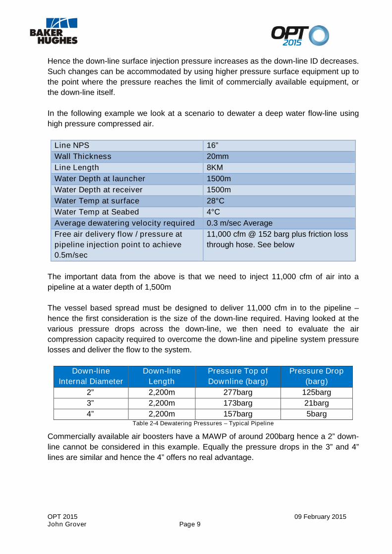
In the following example we look at a scenario to dewater a deep water flow-line using
high pressure compressed air.
Line NPS 16”
Wall Thickness 20mm
Line Length 8KM
Water Depth at launcher 1500m
Water Depth at receiver 1500m
Water Temp at surface 28°C
Water Temp at Seabed 4°C
Average dewatering velocity required 0.3 m/sec Average
Free air delivery flow / pressure at
pipeline injection point to achieve
0.5m/sec
11,000 cfm @ 152 barg plus friction loss
through hose. See below
The important data from the above is that we need to inject 11,000 cfm of air into a
pipeline at a water depth of 1,500m
The vessel based spread must be designed to deliver 11,000 cfm in to the pipeline –
hence the first consideration is the size of the down-line required. Having looked at the
various pressure drops across the down-line, we then need to evaluate the air
compression capacity required to overcome the down-line and pipeline system pressure
losses and deliver the flow to the system.
Down-line
Internal Diameter
Down-line
Length
Pressure Top of
Downline (barg)
Pressure Drop
(barg)
2” 2,200m 277barg 125barg
3” 2,200m 173barg 21barg
4” 2,200m 157barg 5bargTable 2-4 Dewatering Pressures – Typical Pipeline
Commercially available air boosters have a MAWP of around 200barg hence a 2” down-
line cannot be considered in this example. Equally the pressure drops in the 3” and 4”
lines are similar and hence the 4” offers no real advantage.

OPT 2015 09 February 2015John Grover Page 10
Coiled Tubing System Design2.3.3
Initial evaluation of a number of deep water pipeline projects indicated that compressed
air injection rates in excess of 10,000cfm would be required, injected on to a down-line
up to 3,000m long.
Engineering for such scenarios showed that the 2” coiled tubing used to date is not large
enough for these flow rates, with the high pressure drop equating to surface pressures
greater than could be achieved. Thus engineering focused on the two largest pipe sizes
available:
2 7/8” pipe is readily available and there is considerable experience with this pipe
in down hole applications.
3 ½” is not widely used in down hole applications, but it is manufactured, and
readily available. These larger pipe sizes have much lower pressure drop, and so
are better suited for these applications
In looking at reel dimensions it was decided to opt for a reel that would handle 3000m of
2 7/8” and around 2300m of 3 1/2” pipe. This gives reel dimensions of 96” (2.43m)
between flanges, with a core diameter of 120” (3.05m) and flange diameter of 180”
(4.57m), and reel skid dimensions of 223” (5.66m) long, 144” (3.65m) wide and 182” high
(4.66m). The weight of the skid with pipe is 90,000 lbs (41,000kg).
It was decided to mount the rest of the equipment on a single skid for ease of
transportation and lifting. This skid also provides the basis of the overboard deployment
system. A trolley system is used, which allows the pipe and ancillary equipment to be
rigged up in-board of the vessel and then jacked out over the side of the vessel. The
primary driver for this was an “over the side” deployment scenario, but this would work
just as well for a moon pool deployment. The skid accommodates the control cabin, the
power pack, the gooseneck and all ancillary equipment in its transport mode. In use the
control cabin is lifted off the skid and is replaced by the tubing reel, which partially
balances the weight of the tubing when deployed over the side. The cabin can be
located in a number of places around the skid within a 30 ft radius of the power pack,
giving flexibility depending on vessel layout. The main transport skid if 40ft (12.2m) long
by 12ft (3.65m) wide, weighing approximately 80,000lbs, so although it is a permit load it
can be transported by conventional truck. The use of a spreader beam gives a single
point DNV certified lift for offshore lifting.

OPT 2015 09 February 2015John Grover Page 11
Figure 2-7 Coiled Tubing unit in transit mode, showing main deployment skid and reel
The power pack, injector, gooseneck and control cabin are all effectively standard
components. The reel is also standard in the way it functions, but the dimensions are
unique to meet the criteria outlined above.
Beyond that there are several unique components to meet the specific needs of the
application. As we are not using the coil in a well, there is no need for a traditional
blowout preventer (BOP). However there are several functions that the BOP provides
that were deemed necessary in this application. Although a subsea quick disconnect
coupling can be used with the system it was deemed necessary to have a tubing cutter
built into the system, as a means of last resort in the case of extreme weather. This is
mounted directly underneath the injector, and is hydraulically actuated from the control
cabin.
In the event of injector failure with the pipe deployed it was advisable to have a
mechanism to hold the pipe in place while repairs were affected on the injector. A tubing
clamp above the injector, rated for the full weight of pipe deployed is built into the stack.
For these large pipe sizes it was decided to include a tubing straightener into the system.
With no well to constrain the pipe it was deemed a necessity, as no residual curvature in
the pipe is desired in this application.
The tower on which the trolley is mounted has a storage well in which to transport the
clump weight which is attached to the bottom of the coil during deployment. A spacer
frame is mounted on the trolley underneath the injector. This allows the clump weight
and bottom hole assembly to be attached to the bottom of the coiled tubing string and
retracted into the spacer frame to facilitate deployment over the side of the vessel.
OPT 2015 09 February 2015John Grover Page 12
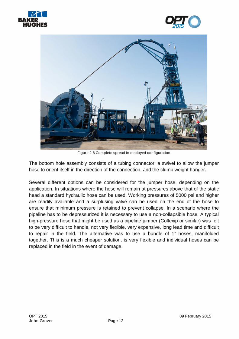
Figure 2-8 Complete spread in deployed configuration
The bottom hole assembly consists of a tubing connector, a swivel to allow the jumper
hose to orient itself in the direction of the connection, and the clump weight hanger.
Several different options can be considered for the jumper hose, depending on the
application. In situations where the hose will remain at pressures above that of the static
head a standard hydraulic hose can be used. Working pressures of 5000 psi and higher
are readily available and a surplusing valve can be used on the end of the hose to
ensure that minimum pressure is retained to prevent collapse. In a scenario where the
pipeline has to be depressurized it is necessary to use a non-collapsible hose. A typical
high-pressure hose that might be used as a pipeline jumper (Coflexip or similar) was felt
to be very difficult to handle, not very flexible, very expensive, long lead time and difficult
to repair in the field. The alternative was to use a bundle of 1” hoses, manifolded
together. This is a much cheaper solution, is very flexible and individual hoses can be
replaced in the field in the event of damage.

OPT 2015 09 February 2015John Grover Page 13
Figure 2-9 Bottom hole assembly and jumper hose ready for connection to PLET
OPT 2015 09 February 2015John Grover Page 14
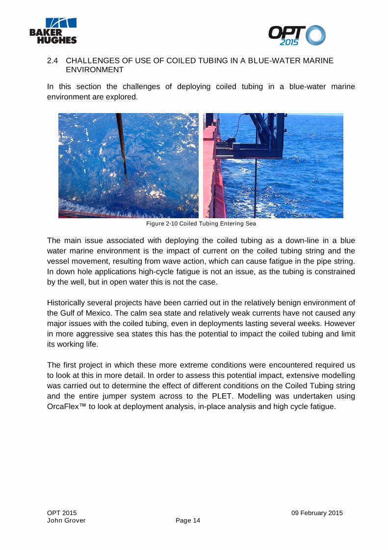
2.4 CHALLENGES OF USE OF COILED TUBING IN A BLUE-WATER MARINEENVIRONMENT
In this section the challenges of deploying coiled tubing in a blue-water marine
environment are explored.
Figure 2-10 Coiled Tubing Entering Sea
The main issue associated with deploying the coiled tubing as a down-line in a blue
water marine environment is the impact of current on the coiled tubing string and the
vessel movement, resulting from wave action, which can cause fatigue in the pipe string.
In down hole applications high-cycle fatigue is not an issue, as the tubing is constrained
by the well, but in open water this is not the case.
Historically several projects have been carried out in the relatively benign environment of
the Gulf of Mexico. The calm sea state and relatively weak currents have not caused any
major issues with the coiled tubing, even in deployments lasting several weeks. However
in more aggressive sea states this has the potential to impact the coiled tubing and limit
its working life.
The first project in which these more extreme conditions were encountered required us
to look at this in more detail. In order to assess this potential impact, extensive modelling
was carried out to determine the effect of different conditions on the Coiled Tubing string
and the entire jumper system across to the PLET. Modelling was undertaken using
OrcaFlex™ to look at deployment analysis, in-place analysis and high cycle fatigue.

OPT 2015 09 February 2015John Grover Page 15
Orcaflex™ requires the following inputs in order to model the behavior of the Coiled
Tubing:
Detailed physical parameters of the coiled tubing and all the equipment attached
to the end of the string in the various deployed conditions
MetOcean data
Vessel data and details of the hang-off point for the coiled tubing
RAO data for the vessel
Specific issues to be addressed as part of the analysis:
Allowable yield stress utilization in the coil tubing across the range of conditions
that could be encountered during operations
Assess the need for a bend stiffener for the coiled tubing based on the above
Look at vortex induced vibration (VIV) and whether lock-in would occur
Evaluate the movement of the hose bundle during the operation and assess the
need for buoyancy and a bend restrictor to prevent the MBR being exceeded
Evaluate potential clashing of the coiled tubing and/or hose bundle with vessel's
hull during deployment
Look at the likely tension and bending moments in the hose bundle and the
breakaway coupling during the operation
The initial static analysis of the system revealed that a bend stiffener was required.
Without one, the current acting on the coiled tubing would cause an overbend in the
string at the vessel interface. Various types of bend stiffener were evaluated, and a steel
tube of reducing wall thickness was agreed upon, which would limit the radius of
curvature of the coil, and allow progressively more bending of the coil over its length.
With this in place the bend of the coiled tubing is limited in all cases of Hs less than 3m
to below the allowable limits of stress utilization based on curvature and tension.
Figure 2-11 Sketch of proposed bend stiffener

OPT 2015 09 February 2015John Grover Page 16
In many instances with the vessel in a fixed position it is possible for the hose and BHA
to be tensioned beyond their design limit, so in order to prevent this it is necessary to
move the vessel, such that the BHA remains within a given target area, so that the hose
and breakaway connector are not overly stressed. Buoyancy and weights are attached to
the hose bundle so that it remains in a lazy S shape during the operation, without undue
tension or bending moments being applied to any of the components.
Vortex induced vibration was found to be present in the initial analysis without the bend
stiffener, but the use of the bend stiffener reduced this to the point where it was no
longer an issue. Contact between the tubing and the side of the vessel is possible in high
current scenarios, so the vessel may have to be oriented accordingly to avoid this.
With the bend stiffener designed as described the coil was analysed for fatigue. As
indicated earlier high-cycle fatigue is a major concern in this application given the
constant movement of the vessel. In this particular instance the coil was anticipated to be
deployed for around 32 days continuously. For a single deployment fatigue was not
determined to be an issue in this case. However it should be noted that in the case of
multiple deployments, the coil is also subjected to low cycle fatigue each time it goes
over the gooseneck. The combination of these two fatigue regimes requires further
investigation to come up with a probable ultimate fatigue life of the coil.
In summary there are multiple parameters than must be considered and modelled prior
to deploying coiled tubing in a blue-water environment. With projects ongoing in
Australia, Brazil, China and Norway data will be gathered and analysed against earlier
fatigue predictions. This will lead to the development of enhanced analysis techniques
for future projects.

OPT 2015 09 February 2015John Grover Page 17
Part 2 – Innovative Wet Buckle Contingency Solutions Using a Coiled Tubing3Down Line
3.1 A BRIEF INTRODUCTION TO WET BUCKLE CONTINGENCY TECHNIQUES
Many subsea pipeline installation projects employ some kind of system to mitigate
against the effects of a wet buckle, should such an event occur. In this section we
discuss the needs for such a system, the options available, and the limitations.
A wet buckle is best defined as an unplanned event where the pipeline has been
damaged and the integrity of the pipeline has been lost. The sea water enters the air
filled pipeline and displaces the air. Damage may be caused by excessive forces from
the lay vessel, effects from the sea bottom conditions or mechanical damage from
anchors.
The typical result of the wet buckle event is that the increased weight of the seawater in
the pipeline will overload the tensioners on the lay vessel and cause the pipeline to be
released from the lay vessel to the seabed further damaging the pipeline and exposing
the pipeline end to further ingress of sea water. The lay vessel typically will not be able to
recover the pipeline until the pipeline has been emptied of water and a suitable
connection point is installed on the pipeline.
In addition to the physical damage to the pipeline the untreated sea water and sea
bottom debris will start to corrode the internal surface of the pipeline.
There are many recorded cases of such events, many of which incurred significant
project costs usually recovered through project insurance. Today project insurers are
aware of such risks and often insist that a wet buckle contingency system be available at
short notice during the offshore pipe lay period.
The damaged sections of the pipeline need to be cut using ROV and diamond wire saw
to expose a clean cut section of pipeline. A Pipeline Recovery Tool (PRT) is then
inserted into the cut end and hydraulically engaged to grip and seal the pipeline.

OPT 2015 09 February 2015John Grover Page 18
Figure 3-1 Diagram of PRT
There are various designs of PRT, some of these can launch and receive pigs to assist
in the displacement of the untreated seawater and debris.
The actions required to manage the ingress of untreated sea water and debris from the
pipeline and ultimately recover the pipeline to the lay vessel are dependent on the
composition of the water, debris and time it will take to finish pipe lay and complete the
pre-commissioning.
For a deep water pipeline the usual actions required are:
Remove the untreated water
Inhibit any residual water to prevent further corrosion
Remove debris
Inhibit any residual debris including H2S treatment (if water contains H2S
Remove water either form the full pipeline section, or a partial section
Traditionally the flooding and dewatering spreads are located onshore or in the shallow
water location and the entire pipeline is flooded and dewatered using pigs to separate
the drive mediums. Pigs are launched from a temporary pig trap or startup head
preloaded with contingency pigs, the flooding pigs can be discharged subsea but the
dewatering pig must be caught in the PRT. Once the pipeline is dewatered the lay vessel
can recover the pipeline and continue the pipe lay operation.

OPT 2015 09 February 2015John Grover Page 19
In the case of long, large diameter and deep water pipelines the flooding and particularly
the dewatering spreads can become very large requiring significant investment to
recover the pipeline in an acceptable time frame.
Discharging a significant volume of chemically treated water to enable recovery of the
pipeline may also be restricted due to environmental concerns or discharge permit
restrictions if the entire pipeline volume must be displaced.
Figure 3-2 WBC Air Spread Stored Onshore

OPT 2015 09 February 2015John Grover Page 20
3.2 USING COILED TUBING TO PARTIALLY DEWATER AND DEPRESSURISE ADEEP WATER PIPELINE SECTION
In section 3.1 the applications and limitation of wet buckle contingency systems were
discussed.
However for large bore, deep water pipelines such as Galsi, Polarled and South Stream
the compressed air spread required to dewater the line is huge and the dewatering time
very slow.
As an example, to South Stream pipeline would require a standby dewatering spread to
be located in the vicinity of the subsea initiation head. This vessel based spread
requirements are shown in this table:
Air requirement
(scfm)
Av.
Velocity
(m/sec)
Days for
800km
No. of
compressors
(1,050scfm)
No. of air
boosters
(2,070scfm)
Vessel Deck
Space
Required
Est. diesel
consumption
(litres/day)
53,000 0.3 31 51 26 2,700m2 236,000
40,000 0.23 40 38 20 2,400m2 179,000
Table 3-1Examples of Conventional WBC Dewatering Spreads
Furthermore with South Stream having a DNV hydro-test waiver, there is no post hydro-
test dewatering, and hence no other need for a full dewatering system other than to
support wet buckle contingency.
To mitigate this vast contingency requirement Baker Hughes developed a solution to
partially dewater, isolate, and depressurize a short deep water section using a large-bore
coiled tubing down-line.

OPT 2015 09 February 2015John Grover Page 21
This technique is summarised as follows:
1. An unplanned flooding event occurs. WBC flooding spread commissioned.
2. WBC flooding pig receiver / catching head installed. Head fitted with 12” discharge
port for air / water outlet during WBC flooding operation.
3. Line then flooded with filtered, treated sea water from WBC flooding spread and
free flood untreated seawater displaced with treated seawater within 20 days.
Water treated for a pre-agreed wet park period.
4. WBC flooding pig receiver then recovered to surface and a Pipeline Recovery
Tool (PRT) installed with a pre-loaded Smart Plug
5. Concurrently line Coiled Tubing (CT) dewatering system installed on a DP vessel
6. Once function tested the CT dewatering system is deployed to the recovery head
7. Smart Plug propelled about 3km to 5km in to the line and treated water
discharged at WBC pumping location. This can be conducted at a lower velocity
than conventional dewatering.
8. Smart Plug set and air pressure bled down at surface
Figure 3-3 Schematic of Partial Dewatering Spread
9. Lay barge recovers line to surface and pipelay can recommence.
10.Thus leaving the Smart Plug in place until dewatering operations commence after
completion of pipelay.

OPT 2015 09 February 2015John Grover Page 22
With this technique we can then use the dewatering air pressure to equalise across the
Smart Plug and then push it to receiver as part of the dewatering train. We also have the
option to relocate the dewatering system to either end of the line depending on Smart
Plug final location and manufacturer recommendation.
The benefits of this solution are clearly demonstrated in this table and in the bullet points
here:
Air requirement
(scfm)
Av.
Velocity
(m/sec)
Days for
5km
No. of
compressors
(1,050scfm)
No. of air
boosters
(2,070scfm)
Vessel Deck
Space
Required
Est. diesel
consumption
(litres/day)
10,200 0.1 0.5 11 5 900m2 25,600Table 3-2 Example of Partial Dewatering Spread
Lower cost related to WBC contingency equipment – which is rarely used!
Smaller vessel requirement on standby.
Reduced fuel requirements.
It the event that a Partial Wet Buckle Dewatering System is used; final dewatering
can be conducted after shore tie-in and during conventional pre-commissioning
period.
In summary (based on the South Stream example):
Key Issue Partial Dewatering Conventional Dewatering
Dewatering Time
Much Better – 2 days
including deployment &
recovery
Much Worse – 31days @
min of 0.3m/sec
Deck Space
Much Better – a spread
designed for 0.1m/sec
requires approx. 880 m2 of
deck space
Much Worse – a spread
designed for min 0.3m/sec
requires in excess of
3,300m2
Fuel UsageMuch Better – total of 25,600
litres
Much Worse – total of
7,300,000 litres
Equipment Cost
Significantly Better – even
excluding fuel 1/3 of the cost
of std. WBC.
Much Worse – excluding
fuel at least 3 x the cost of
partial dewatering.
Installation Vessel
Standby
Better – excluding flooding
vessel standby could be less
than 5 days
Worse – excluding flooding
standby could be 40 days
Table 3-3 Comparison of Partial and Conventional WBC Dewatering

OPT 2015 09 February 2015John Grover Page 23
SUMMARY AND CONCLUSIONS4With this paper the authors have endeavoured to demonstrate the following:
1. That down-lines play an important role in the pre-commissioning of deep waterpipelines
2. That coiled tubing should be considered as the preferred down-line system exceptwhere very large bore down-lines are required. Even then multiple coiled tubingdown-lines can be considered as an alternative.
3. That custom marine coiled tubing systems provide the flexibility for moon-pool orover-the-side deployment and are largely self-supporting once installed.
4. That engineering and modelling is required prior to deploying coiled tubing in ablue-water environment.
5. That a partial dewatering system offers a faster, lower cost alternative to a full wetbuckle contingency dewatering system, especially for pipelines not intended forhydrostatic pressure testing.