Embed Size (px)
Citation preview

TRU Corporation offers a broad range of standard 7-16 series panel mount
receptacles for use in both commercial and military applications. These
standard designs offer outstanding quality, performance and rapid availability.
Our standard 7-16 series designs are available with either a slotted finger or
a solid wall interface design to optimize your performance requirements.
A slotted finger interface provides mechanically robust resistance against
shock and vibration. A solid wall interface offers benefits of lower passive
intermodulation (PIM) performance. Our PIM performance is enhanced with
standard tri-metal plating that eliminates the magnetic material in the finish.
The back-end launch designs of this series are modular and allow for rapid
customization of the contact geometry in a cost effective manner. In addition
to the standard product included in this brochure, our design team can make
a custom configuration for your individual application challenge.
Visit our website or contact your local authorized Distribution office
for additional support and product information.
• Standard designs from stock
• Customized modular back-end launch designs
• Tri-metal, non-magnetic plating
• Slotted finger and solid wall interface designs
• PIM (-175 dBc min)
7-16 Series — PanelMount Receptacles
7-16 SeriesPanel Mount Receptacles
TRU 7-16_4 page_031715_Layout 1 3/17/15 10:57 AM Page 1
7-16 SeriesPanel Mount Receptacles
Specifications subject to change without notice. For additional specifications or other products, visit us online or call us at 1-800-262-9878. trucorporation.com
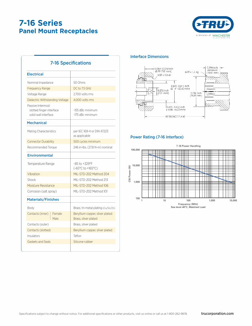
7-16 Specifications
Electrical
Nominal Impedance 50 Ohms
Frequency Range DC to 7.5 GHz
Voltage Range 2,700 volts rms
Dielectric Withstanding Voltage 4,000 volts rms
Passive Intermod: slotted finger interface -155 dBc minimum solid wall interface -175 dBc minimum
Mechanical
Mating Characteristics per IEC 169-4 or DIN 47223 as applicable
Connector Durability 500 cycles minimum
Recommended Torque 246 in-lbs. (27.8 N-m) nominal
Environmental
Temperature Range -85 to +329°F (-65°C to +165°C)
Vibration MIL-STD-202 Method 204
Shock MIL-STD-202 Method 213
Moisture Resistance MIL-STD-202 Method 106
Corrosion (salt spray) MIL-STD-202 Method 101
Materials/Finishes
Body Brass, tri-metal plating (Cu/Sn/Zn)
Contacts (inner) Female Beryllium copper, silver plated
Male Brass, silver plated
Contacts (outer) Brass, silver plated
Contacts (slotted) Beryllium copper, silver plated
Insulators Teflon
Gaskets and Seals Silicone rubber
Frequency (MHz)Sea level 40°C, Matched Load
7-16 Power Handling
CW Power (W)
100,000
10,000
1,000
1001 10 100 1,000 10,000
Power Rating (7-16 Interface)
Interface Dimensions
TRU 7-16_4 page_031715_Layout 1 3/17/15 10:57 AM Page 2
7-16 SeriesPanel Mount Receptacles
Specifications subject to change without notice. For additional specifications or other products, visit us online or call us at 1-800-262-9878. trucorporation.com
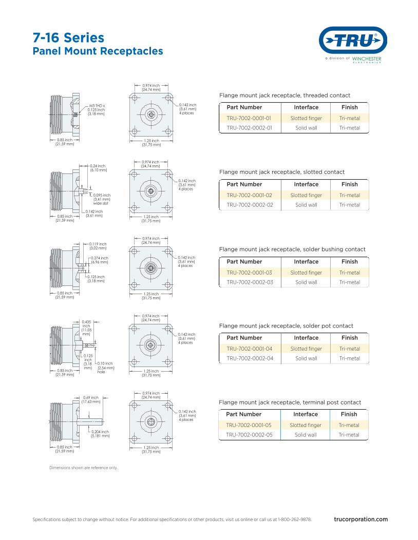
Dimensions shown are reference only.
Flange mount jack receptacle, threaded contact
Part Number Interface Finish
TRU-7002-0001-01 Slotted finger Tri-metal
TRU-7002-0002-01 Solid wall Tri-metal
Flange mount jack receptacle, slotted contact
Flange mount jack receptacle, solder bushing contact
Flange mount jack receptacle, solder pot contact
Flange mount jack receptacle, terminal post contact
Part Number Interface Finish
TRU-7002-0001-02 Slotted finger Tri-metal
TRU-7002-0002-02 Solid wall Tri-metal
Part Number Interface Finish
TRU-7002-0001-03 Slotted finger Tri-metal
TRU-7002-0002-03 Solid wall Tri-metal
Part Number Interface Finish
TRU-7002-0001-04 Slotted finger Tri-metal
TRU-7002-0002-04 Solid wall Tri-metal
Part Number Interface Finish
TRU-7002-0001-05 Slotted finger Tri-metal
TRU-7002-0002-05 Solid wall Tri-metal
M3 THD x0.125 inch(3,18 mm)
0.85 inch(21,59 mm)
0.24 inch(6,10 mm)
0.095 inch(3,41 mm)wide slot
0.142 inch(3,61 mm)
0.85 inch(21,59 mm)
0.119 inch(3,02 mm)
0.274 inch(6,96 mm)
0.125 inch(3,18 mm)
0.85 inch(21,59 mm)
0.435inch
(11,05mm)
0.125inch(3,18 mm)
0.10 inch(2,54 mm)hole
0.85 inch(21,59 mm)
0.69 inch(17,63 mm)
0.204 inch(5,181 mm)
0.85 inch(21,59 mm)
0.974 inch(24,74 mm)
0.142 inch(3,61 mm)4 places
1.25 inch(31,75 mm)
0.142 inch(3,61 mm)4 places
0.974 inch(24,74 mm)
1.25 inch(31,75 mm)
0.142 inch(3,61 mm)4 places
1.25 inch(31,75 mm)
0.974 inch(24,74 mm)
1.25 inch(31,75 mm)
0.142 inch(3,61 mm)4 places
0.974 inch(24,74 mm)
1.25 inch(31,75 mm)
0.974 inch(24,74 mm)
0.142 inch(3,61 mm)4 places
TRU 7-16_4 page_031715_Layout 1 3/17/15 10:57 AM Page 3
7-16 Series
Specifications subject to change without notice. For additional specifications or other products, visit us online or call us at 1-800-262-9878. trucorporation.com
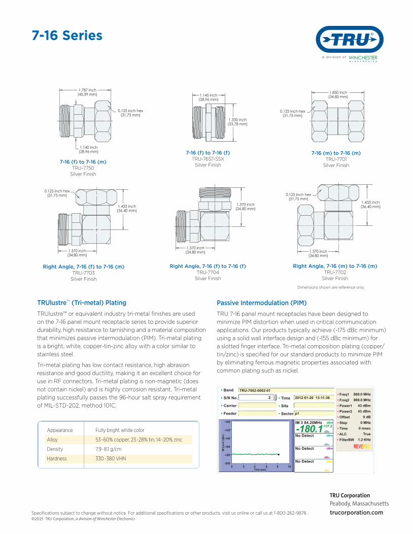
TRUlustre™ (Tri-metal) Plating
TRUlustre™ or equivalent industry tri-metal finishes are used
on the 7-16 panel mount receptacle series to provide superior
durability, high resistance to tarnishing and a material composition
that minimizes passive intermodulation (PIM). Tri-metal plating
is a bright, white, copper-tin-zinc alloy with a color similar to
stainless steel.
Tri-metal plating has low contact resistance, high abrasion
resistance and good ductility, making it an excellent choice for
use in RF connectors. Tri-metal plating is non-magnetic (does
not contain nickel) and is highly corrosion resistant. Tri-metal
plating successfully passes the 96-hour salt spray requirement
of MIL-STD-202, method 101C.
Appearance Fully bright white color
Alloy 53-60% copper, 23-28% tin, 14-20% zinc
Density 7.9-8.1 g/cm
Hardness 330-380 VHN
7-16 (f) to 7-16 (m)TRU-7750Silver Finish
7-16 (f) to 7-16 (f)TRU-7657-SSXSilver Finish
7-16 (m) to 7-16 (m)TRU-7701Silver Finish
Right Angle, 7-16 (f) to 7-16 (m)TRU-7703Silver Finish
Right Angle, 7-16 (f) to 7-16 (f)TRU-7704Silver Finish
Right Angle, 7-16 (m) to 7-16 (m)TRU-7702Silver Finish
1.787 inch(45,39 mm)
1.140 inch(28,96 mm)
0.125 inch hex(31,75 mm)
1.370 inch(34,80 mm)
0.125 inch hex(31,75 mm)
1.433 inch(36,40 mm)
1.370 inch(34,80 mm)
1.370 inch(34,80 mm)
1.433 inch(36,40 mm)
1.370 inch(34,80 mm)
0.125 inch hex(31,75 mm)
T
1.140 inch(28,96 mm)
1.330 inch(33,78 mm)
1.850 inch(34,80 mm)
0.125 inch hex(31,75 mm)
T
Passive Intermodulation (PIM)
TRU 7-16 panel mount receptacles have been designed to
minimize PIM distortion when used in critical communication
applications. Our products typically achieve (-175 dBc minimum)
using a solid wall interface design and (-155 dBc minimum) for
a slotted finger interface. Tri-metal composition plating (copper/
tin/zinc) is specified for our standard products to minimize PIM
by eliminating ferrous magnetic properties associated with
common plating such as nickel.
TRU-7002-0002-01• Band
• S/N No.
• Carrier
• Feeder
2012-01-20 13:11:36• Time
• Site
• Sector p1
2
IM 3 84.20MHz
No Detect
No Detect
No Detect
-100
-120
-140
-160
-180
-2000 2 4 6 8 10 Time (sec)
IM L
evel
(dB
c)
dBm
dBm
dBm
dBm
dBc
dBc
dBc
dBc
-180.1-137.2
• Freq1• Freq2• Power1• Power2• Offset• Step• Time• ALC• FilterBW
869.0 MHz869.0 MHz
43 dBm43 dBm
0 dB0 MHz
0 msec True
1.2 KHz
REVERSE
Dimensions shown are reference only.
TRU CorporationPeabody, Massachusetts
©2015 TRU Corporation, a division of Winchester Electronics
TRU 7-16_4 page_031715_Layout 1 3/17/15 10:57 AM Page 4


![OEM Product Technical Specifications - · PDF fileOEM Product Technical Specifications ... 170 mm direct Mount ... and variation in pad advancement [2]](https://img.dokumen.tips/doc/110x75/5a87fc3c7f8b9aa5408e41cf/oem-product-technical-specifications-product-technical-specifications-170.jpg)