Embed Size (px)
Citation preview

GUID_INSTL_PLP_180222C E
Panel-Loc Plus™
Installation Details
Copyright © 2018, Central States Manufacturing, Inc., All Rights Reserved.
HELPFUL INFORMATION FOR RESIDENTIAL ROOFING
INCLUDES REGIONAL PRODUCTS
Panel-Loc™
CD 2000®


C E N T R A L S T A T E S M A N U F A C T U R I N G , I N C .E f f e c t i v e 0 2 / 2 0 1 8 • I n f o r m a t i o n s u b j e c t t o c h a n g e 3
OUR MISSIONThe men and women at
Central States Manufacturing, Inc. would like to welcome you.
Central States Manufacturing, Inc. is a 100% employee-owned company devoted to the personal growth and well-being of our owners. We are dedicated to increasing the value of our company by making Raving Fans of our customers through exceeding their expectations, being easy to do business with, demonstrating excellence in all aspects of our business and being committed to improving their business.
It is our promise to maintain honesty and integrity with everyone our lives may touch. With thanksgiving for the blessings we have been given, we are committed to serving the communities where we live and work by giving back a portion of our time, talents and profits.

C E N T R A L S T A T E S M A N U F A C T U R I N G , I N C .E f f e c t i v e 0 2 / 2 0 1 8 • I n f o r m a t i o n s u b j e c t t o c h a n g e 4
Important Information & Safety . . . . . . . . . . . . . . . . . . . . . . . . . . . . . . 5Care and Handling . . . . . . . . . . . . . . . . . . . . . . . . . . . . . . . . . . . . . . . . . . . 6Tools and Equipment . . . . . . . . . . . . . . . . . . . . . . . . . . . . . . . . . . . . . . . . 7Field Cutting, Drilling, Fastening. . . . . . . . . . . . . . . . . . . . . . . . . . . . . . 7Roof Preparation . . . . . . . . . . . . . . . . . . . . . . . . . . . . . . . . . . . . . . . . . . . . . 8-9Substructure Squareness. . . . . . . . . . . . . . . . . . . . . . . . . . . . . . . . . . . . . 10-11Installation Overview . . . . . . . . . . . . . . . . . . . . . . . . . . . . . . . . . . . . . . . . 12-13Installing the First Panel . . . . . . . . . . . . . . . . . . . . . . . . . . . . . . . . . . . . . . 14-15Installing Sidelap Panel. . . . . . . . . . . . . . . . . . . . . . . . . . . . . . . . . . . . . . . 16Installing Endlap Panel . . . . . . . . . . . . . . . . . . . . . . . . . . . . . . . . . . . . . . . 17Residential Fascia Trim . . . . . . . . . . . . . . . . . . . . . . . . . . . . . . . . . . . . . . . 18-19Residential Drip Edge . . . . . . . . . . . . . . . . . . . . . . . . . . . . . . . . . . . . . . . . 20-21Residential Eave Trim. . . . . . . . . . . . . . . . . . . . . . . . . . . . . . . . . . . . . . . . . 22-23Valley Trim . . . . . . . . . . . . . . . . . . . . . . . . . . . . . . . . . . . . . . . . . . . . . . . . . . . 24-25Gambrel Trim Lower . . . . . . . . . . . . . . . . . . . . . . . . . . . . . . . . . . . . . . . . . 26-27Gambrel Trim Upper . . . . . . . . . . . . . . . . . . . . . . . . . . . . . . . . . . . . . . . . . 28-29Residential Rake Trim . . . . . . . . . . . . . . . . . . . . . . . . . . . . . . . . . . . . . . . . 30-31Ridge Cap. . . . . . . . . . . . . . . . . . . . . . . . . . . . . . . . . . . . . . . . . . . . . . . . . . . . 32-33Sidewall Trim. . . . . . . . . . . . . . . . . . . . . . . . . . . . . . . . . . . . . . . . . . . . . . . . . 34-35Endwall Flashing . . . . . . . . . . . . . . . . . . . . . . . . . . . . . . . . . . . . . . . . . . . . . 36-37
INDEX
This document illustrates conditions and details that are recommended for this product to minimize the number of potential water penetrations. Each project may have specific situations in which alternate methods may be acceptable. A qualified contractor is able to adapt methods to a particular project.

C E N T R A L S T A T E S M A N U F A C T U R I N G , I N C .E f f e c t i v e 0 2 / 2 0 1 8 • I n f o r m a t i o n s u b j e c t t o c h a n g e 5
IMPORTANT INFORMATIONThis manual contains suggestions and guidelines on how to install Panel-Loc Plus panels. The drawings in this guide are for illustration purposes only and may not apply to all building designs or product applications. The installation details shown are proven methods of construction, but are not intended to cover all instances, building requirements, designs, or codes. It is the responsibility of the designer/installer to ensure that the details meet particular building requirements. The designer/installer must be aware of, and allow for, expansion/contraction of roof panels. The details may require changes or revisions due to each project’s conditions.
There are certain minimum live, snow, dead, collateral, and wind loads that a roof must generally be designed to support. Consult local building officials to determine the appropriate building design load requirements. A professional engineer should be consulted for all roof system designs. It is the buyer’s responsibility to verify all applicable
code requirements, check all measurements, and determine suitability of product for the job. The buyer is also responsible for determining lengths and quantities needed. Prior to ordering and installing materials, all dimensions should be verified with field measurements. Implied warranties of merchantability and fitness for a particular purpose are disclaimed. All Panel-Loc Plus instructions assume that a qualified firm or individual has been contacted regarding application of this product. Failure to comply with stated recommendations relieves the manufacturer of responsibility for any damage or deterioration of the product incurred and voids any applicable warranty.
Central States Manufacturing reserves the right to modify, without notice, information in this guide. If you have questions regarding proper installation of Panel-Loc Plus or information not included in this guide, contact your salesperson.
SAFETY
Always wear heavy gloves when working with steel panels to avoid cuts from sharp edges. If power cutting or drilling steel panels, always wear safety glasses to
prevent eye injury from flying metal fragments.CAUTION
Each job site presents different hazards; therefore it is the responsibility of the contractor to determine the safest way to install Panel-Loc Plus based on the recommended instructions contained in this guide and provide crew members with appropriate safety measures. If you must walk on a metal roof, take great care. Metal panels can become slippery, so always wear shoes with non-slip soles. Avoid working on metal roofs during wet conditions,
when the panels can become extremely slippery. Walking or standing on a metal roof which does not have a plywood or other deck beneath it is not recommended. However, if you must do so, always walk on the purlins, never between.
OSHA safety regulations should be complied with at all times.
NOTEAlthough installation details shown also apply to Panel-Loc and CD2000 profiles,
follow the appropriate fastener spacing for each profile.
Fastener spacing can be found at centralstatesmfg.com

C E N T R A L S T A T E S M A N U F A C T U R I N G , I N C .E f f e c t i v e 0 2 / 2 0 1 8 • I n f o r m a t i o n s u b j e c t t o c h a n g e 6
RECEIVING MATERIALSWhen unloading panels, extreme caution must be employed. Care needs to be used when unloading panels with a forklift. Panel edges and underside paint may become damaged if the forklift driver does not use caution.
STORAGEAll materials should be stored in a dry place, preferably under a roof. Panels and trim are subject to staining and premature rusting when water sits upon, or becomes trapped between them. You may stand panels on end and fan them out at the bottom to provide air circulation and moisture run off. If space does not allow for this, the panels should be separated, blocked off the ground at least 12 inches to allow air flow and stored at an incline to encourage drainage. The panels should then be covered in a manner to still allow airflow through the sheets. Do not use a plastic cover, as this may cause the panels to sweat or condensation to occur.
Failure to properly store panels and trim could result in product failure that is not covered by manufacturers warranty.
HANDLINGWhen unbundling the panels, never drag them across the surface of one another. This may cause scratches across the underneath panels. It is recommended that the panels be “rolled” off the top of the bundle to prevent scratching. Panels should only be lifted and carried by their sides.
Panel edges are very sharp, therefore, safety equipment should be worn by all workers handling the material.
FOOT TRAFFICCare of metal panels and flashings must be exercised throughout installation. Foot traffic can cause distortion of panel and damage to finish. Traffic over the installed roof must be kept to an absolute minimum.
If walking on the roof panels is unavoidable, walk only on the minor ribs to minimize damage.
CARE AND HANDLING
• Gloves
• Safety Glasses
• Snips/hand shear
• Tape Measure
• Chalk Line
• Electric Metal Shear
• Cordless Drill
• Caulking Gun
• Blind Rivet Tool
TOOLS & EQUIPMENT• Gloves
• Safety Glasses
• Snips/hand shear
• Tape Measure
• Chalk Line
• Electric Metal Shear
• Cordless Drill
• Caulking Gun
• Blind Rivet Tool
TOOLS & EQUIPMENT
C E N T R A L S T A T E S M A N U F A C T U R I N G , I N C .E f f e c t i v e 0 2 / 2 0 1 8 • I n f o r m a t i o n s u b j e c t t o c h a n g e 7
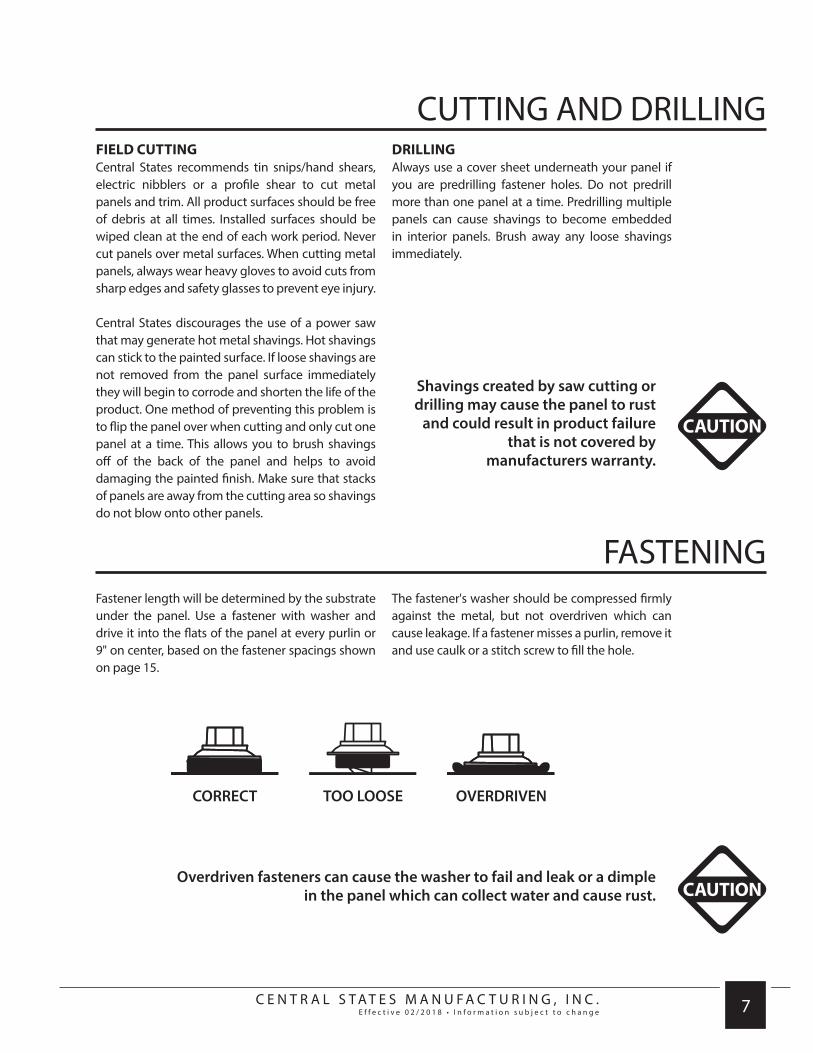
FIELD CUTTINGCentral States recommends tin snips/hand shears, electric nibblers or a profile shear to cut metal panels and trim. All product surfaces should be free of debris at all times. Installed surfaces should be wiped clean at the end of each work period. Never cut panels over metal surfaces. When cutting metal panels, always wear heavy gloves to avoid cuts from sharp edges and safety glasses to prevent eye injury.
Central States discourages the use of a power saw that may generate hot metal shavings. Hot shavings can stick to the painted surface. If loose shavings are not removed from the panel surface immediately they will begin to corrode and shorten the life of the product. One method of preventing this problem is to flip the panel over when cutting and only cut one panel at a time. This allows you to brush shavings off of the back of the panel and helps to avoid damaging the painted finish. Make sure that stacks of panels are away from the cutting area so shavings do not blow onto other panels.
DRILLINGAlways use a cover sheet underneath your panel if you are predrilling fastener holes. Do not predrill more than one panel at a time. Predrilling multiple panels can cause shavings to become embedded in interior panels. Brush away any loose shavings immediately.
CAUTION
Shavings created by saw cutting or drilling may cause the panel to rust
and could result in product failure that is not covered by
manufacturers warranty.
CUTTING AND DRILLING
Fastener length will be determined by the substrate under the panel. Use a fastener with washer and drive it into the flats of the panel at every purlin or 9" on center, based on the fastener spacings shown on page 15.
The fastener's washer should be compressed firmly against the metal, but not overdriven which can cause leakage. If a fastener misses a purlin, remove it and use caulk or a stitch screw to fill the hole.
CAUTIONOverdriven fasteners can cause the washer to fail and leak or a dimple
in the panel which can collect water and cause rust.
FASTENING
CORRECT TOO LOOSE OVERDRIVEN

C E N T R A L S T A T E S M A N U F A C T U R I N G , I N C .E f f e c t i v e 0 2 / 2 0 1 8 • I n f o r m a t i o n s u b j e c t t o c h a n g e 8
ROOF PREPARATIONPanel-Loc Plus can be installed over existing shingles, over solid decking or over purlins/open framing.
It is the responsibility of the contractor to ensure a suitable substrate prior to the application of Panel-Loc Plus. Substructures should be designed to meet all necessary code requirements. Green lumber is not recommended as moisture can damage the metal panels and cause fasteners to back out.
Distortion in the panel caused by an uneven substrate, ripples, or laps in the vapor barrier, debris, protruding nails and staples, button cap nails, etc., are not defects in the materials and are not the responsibility of Central States. To minimize distortions from an uneven substrate, use Retroease or 1x4 furring strips.
EXISTING SHINGLES1. Make sure any existing decking is smooth, level and in good condition.
Remove any damaged shingles or debris that might interfere with installation.
2. Apply 30 lb. felt or synthetic underlayment using nails or staples.
3. Apply 1x4 furring strips or Retroease horizontally, every 2' on center. These strips will act as purlin framing that you will fasten panels to.
4. Check for roof squareness. Follow guidelines on page 10.
5. Begin installation of trim and panels following guidelines on pages 12-13.
2'
CAUTIONCheck local codes when installing metal roofing over existing shingles. It is not recommended to install over more than 2 layers of shingles. Shingles may rot between layers due to trapped moisture, or substructure may fail due to weight of shingles and metal roof.

C E N T R A L S T A T E S M A N U F A C T U R I N G , I N C .E f f e c t i v e 0 2 / 2 0 1 8 • I n f o r m a t i o n s u b j e c t t o c h a n g e 9
ROOF PREPARATION
SOLID DECKING1. Make sure decking is smooth, level and in good condition. Remove any
debris that might interfere with installation.
2. Apply 30 lb. felt or synthetic underlayment using nails or staples.
3. Check for roof squareness. Follow guidelines on page 10.
4. Begin installation of trim and panels following guidelines on pages 12-13.
OPEN FRAMINGPanel-Loc Plus can be install directly over purlins/wood framing. Maximum purlin spacing is 2'. This method should only be used for heated spaces if adequate protection against condensation is used. Without this protection, the underside of the panel may collect condensation and drip into structure.
1. Check for roof squareness. Follow guidelines on page 10.
2. Begin installation of trim and panels following guidelines on pages 12-13.

C E N T R A L S T A T E S M A N U F A C T U R I N G , I N C .E f f e c t i v e 0 2 / 2 0 1 8 • I n f o r m a t i o n s u b j e c t t o c h a n g e 10
SUBSTRUCTURE SQUARENESSThe installer should check the roof deck for squareness before installation. Panel distortion may occur if not applied over properly aligned and uniform substructure. Several methods can be used to verify squareness of the structure for proper installation of the panels.
If the structure is out of square, you can use the 3-4-5 triangle method to create an alignment line to start your first run of panels.
A B
1 2 3
3'
4'
5'
1. Starting at the eave and 1/2" from the rake, place a nail at POINT A
2. From POINT A, measure over 3' parallel with the eave and place a nail at POINT B.
The main goal is to create a triangle with sides that are 3', 4' and 5'. When this is accomplished you know you have a right angle at the eave to rake and can create an alignment line that is square.
OVERVIEW
STEP 1
CAUTIONCorrect any squareness issues as early in the installation as possible. It might not appear to be a problem at the beginning, but if left uncorrected it will be very noticeable in the end.
RIDGE
EAVE
RAKE
RIDGE
EAVE
RAKE

C E N T R A L S T A T E S M A N U F A C T U R I N G , I N C .E f f e c t i v e 0 2 / 2 0 1 8 • I n f o r m a t i o n s u b j e c t t o c h a n g e 11
AA
A B
1"
2"
3"
4"
1"
2"
3"
4"
5"
C
A B
453. Hook one tape measure to
POINT A and run it up the rake, approximately 4' towards the ridge.
4. Hook a second tape measure to POINT B and run it diagonal towards the first tape measure to approximately 5'.
5. Mark POINT C with a nail where tape measure one at 4' meets tape measure two at 5'.
4
3
2
1
3
2
1
6. Snap a chalk line from the nails at POINT A and POINT C. This is your alignment line to start your first panel on.
7. Additional reference lines can be marked ahead of panel installation by snapping a parallel line 10' from your first line. Then as panels are installed you can measure points at the eave and ridge against this second line to see if the panels are still running square.
C
STEP 2
STEP 3
RIDGE
EAVE
RAKE
RIDGE
EAVE
RAKE

C E N T R A L S T A T E S M A N U F A C T U R I N G , I N C .E f f e c t i v e 0 2 / 2 0 1 8 • I n f o r m a t i o n s u b j e c t t o c h a n g e 12
INSTALLATION OVERVIEWInstallation order will vary from roof to roof. Recommended installation of Panel-Loc Plus is shown below. The contractor will determine which conditions apply.
MOISTURE BARRIERNOTE: Install any additional ice and water shield in valleys if appropriate at this time.
FASCIA TRIM EAVE TRIM
VALLEY TRIM PANELS GAMBREL TRIMS
321
654

C E N T R A L S T A T E S M A N U F A C T U R I N G , I N C .E f f e c t i v e 0 2 / 2 0 1 8 • I n f o r m a t i o n s u b j e c t t o c h a n g e 13
PANELS RAKE TRIM RIDGECAP
SIDEWALL ENDWALL COMPLETED
987
121110

C E N T R A L S T A T E S M A N U F A C T U R I N G , I N C .E f f e c t i v e 0 2 / 2 0 1 8 • I n f o r m a t i o n s u b j e c t t o c h a n g e 14
INSTALLING THE FIRST PANEL
PREVAILING WINDS
Panels should be installed in the correct sequence as shown on pages 12-13. Install panels with the sidelap facing away from the prevailing wind.
CAUTIONCopper metallic panels must be installed in the same direction!See directional arrows or stickers provided with your metal panel order.
SIDELAP

C E N T R A L S T A T E S M A N U F A C T U R I N G , I N C .E f f e c t i v e 0 2 / 2 0 1 8 • I n f o r m a t i o n s u b j e c t t o c h a n g e 15
9"
9"Fastener Pattern at Eave and Endlap
Fastener Pattern at Interior of Panel
1. Start the first panel at the alignment line you created on page 11.
2. The panel should overhang from the eave a desired amount. If installing gutters, a 1" overhang is suggested. An overhang of 6" or more may not support weight of snow or debris.
3. Fasten at the eave according to the fastener pattern below. The fasteners should penetrate through the inside closure, through the eave trim and into the substrate below.
4. Continue by fastening the panel every 2' running towards the ridge. Use the interior panel fastener pattern.
5. Continue with panel run using sidelaps. If necessary use an endlap condition shown on page 15.
9"
9"
RIDGE
EAVE
RAKE
ALIGNMENT LINE
2'
NOTE Fastener spacing for Panel-Loc or CD2000 can be found at www.centralstatesmfg.com.

C E N T R A L S T A T E S M A N U F A C T U R I N G , I N C .E f f e c t i v e 0 2 / 2 0 1 8 • I n f o r m a t i o n s u b j e c t t o c h a n g e 16
PREVAILING WINDS
INSTALLING SIDELAP PANELAfter the first panel is secure, proceed with the next panel by overlapping it on the side. Continue with fastener pattern shown on page 15.
CAUTIONDo not damage the siphon groove by using a stitch screw on top of the major rib or clog it with butyl tape.
Panel-Loc Plus Siphon Groove
OVERLAP

C E N T R A L S T A T E S M A N U F A C T U R I N G , I N C .E f f e c t i v e 0 2 / 2 0 1 8 • I n f o r m a t i o n s u b j e c t t o c h a n g e 17
INSTALLING ENDLAP PANEL
1. Starting at 3" from the end of the panel to be lapped, apply a line of butyl tape over the ribs.
2. Overlap the next panel 6".
3. Fasten the two panels together through the butyl tape and into the substrate below. This should be about 3" back from the overlapping panel.
4. Continue by fastening the panel every 2' running towards the ridge. Use the interior panel fastener pattern.
This application may not be required.
6"3"

C E N T R A L S T A T E S M A N U F A C T U R I N G , I N C .E f f e c t i v e 0 2 / 2 0 1 8 • I n f o r m a t i o n s u b j e c t t o c h a n g e 18
RESIDENTIALEAVE TRIM
ILLUSTRATED TRIMS:
30 LB. FELT PAPER (MINIMUM)
PANEL-LOC PLUS
#10 FASTENER
#10 FASTENER
INSIDE CLOSURE AND BUTYL TAPE
SOLID DECKING
FASCIA TRIMRFT312(color)RFT512(color)RFT712(color)
Painted side
RESIDENTIAL FASCIA TRIM
PANCAKE HEAD FASTENER
RESIDENTIAL FASCIA TRIM
Choose trim with leg length that best covers the fascia board.
FASCIA BOARD

C E N T R A L S T A T E S M A N U F A C T U R I N G , I N C .E f f e c t i v e 0 2 / 2 0 1 8 • I n f o r m a t i o n s u b j e c t t o c h a n g e 19
1. Choose a RFT with a leg length that best covers the fascia board.
2. Place RFT at fascia board and make sure roof felt overlaps RFT.
3. Fasten RFT to bottom of fascia board at 24" on center.
4. Continue by installing either Residential Drip Edge or Residential Eave Trim.
DIRECTIONS:
RESIDENTIAL EAVE TRIM
PANEL-LOC PLUS
RESIDENTIAL FASCIA TRIM
SOLID DECKING
30 LB. FELT PAPER (MINIMUM)
#10 FASTENERINSIDE CLOSURE
AND BUTYL TAPE
FASCIA BOARD
PANCAKE HEAD
FASTENER

C E N T R A L S T A T E S M A N U F A C T U R I N G , I N C .E f f e c t i v e 0 2 / 2 0 1 8 • I n f o r m a t i o n s u b j e c t t o c h a n g e 20
ILLUSTRATED TRIMS:
NOTE: Residential Drip Edge is not recommended when using seamless gutters. Choose Residential Eave Trim instead.
RESIDENTIAL DRIP EDGE
PANEL-LOC PLUS
INSIDE CLOSURE AND BUTYL TAPE
#10 FASTENER
RESIDENTIAL DRIP EDGERDC(color)
pitch Painted side
RESIDENTIAL FASCIA TRIM
RESIDENTIAL DRIP EDGE
Specify pitch when ordering trim.
30 LB. FELT PAPER (MINIMUM)
SOLID DECKING
PANCAKE HEAD FASTENER

C E N T R A L S T A T E S M A N U F A C T U R I N G , I N C .E f f e c t i v e 0 2 / 2 0 1 8 • I n f o r m a t i o n s u b j e c t t o c h a n g e 21
1. Fasten the RDC to the roof deck as shown with appropriate fastener. Fastener spacing is not important because the panel will fasten through the trim in a later step. Pancake head screws are recommended for this portion of application. If you are using a hex-head screw, fasteners should be placed appropriately to be hidden under the panel rib. Fasteners should be placed no more than .75” from the top of trim to allow for closure placement in later step.
2. Place a run of butyl tape directly between edge of fastener and edge of roof. Then install inside closure on top of the butyl tape. Place another run of tape on top of inside closure.
3. Place panel on roof, aligning with inside closure. The edge of the panel should be aligned with the edge of the RDC overhanging the fascia.
4. Fasten panel according to fastener pattern, fastening through the closure, into the roof.
DIRECTIONS:
RESIDENTIAL DRIP EDGE
INSIDE CLOSURE AND BUTYL TAPE
SOLID DECKING
When overlapping RDCs, trim off kickout at bottom of trim on underlapping trim.TIP
#10 FASTENER
RESIDENTIAL FASCIA TRIM
PANCAKE HEAD
FASTENER
PANEL-LOC PLUS
30 LB. FELT PAPER (MINIMUM)

C E N T R A L S T A T E S M A N U F A C T U R I N G , I N C .E f f e c t i v e 0 2 / 2 0 1 8 • I n f o r m a t i o n s u b j e c t t o c h a n g e 22
ILLUSTRATED TRIMS:
NOTE: Use with seamless gutters applications.
30 LB. FELT PAPER (MINIMUM)
SOLID DECKING
RESIDENTIAL EAVE TRIMRET(color)
Painted side
RESIDENTIALEAVE TRIM
PANEL-LOC PLUS
INSIDE CLOSURE AND BUTYL TAPE
#10 FASTENER
RESIDENTIAL FASCIA TRIM
PANCAKE HEAD FASTENER
RESIDENTIAL EAVE TRIM
Specify pitch when ordering trim.

C E N T R A L S T A T E S M A N U F A C T U R I N G , I N C .E f f e c t i v e 0 2 / 2 0 1 8 • I n f o r m a t i o n s u b j e c t t o c h a n g e 23
1. Fasten the RET to the roof deck as shown with appropriate fastener. Fastener spacing is not important because the panel will fasten through the trim in a later step. Pancake head screws are recommended for this portion of application. If you are using a hex-head screw, fasteners should be placed appropriately to be hidden under the panel rib. Fasteners should be placed no more than .75” from the top of trim to allow for closure placement in later step.
2. Place a run of butyl tape directly between edge of fastener and edge of roof. Then install inside closure on top of the butyl tape. Place another run of tape on top of inside closure.
3. Place panel on roof, aligning with inside closure. The edge of the panel should be placed at the desired overhang of the fascia.
4. Fasten panel according to fastener pattern, fastening through the closure, into the roof.
DIRECTIONS:
RESIDENTIAL EAVE TRIM
INSIDE CLOSURE AND BUTYL TAPE
SOLID DECKING
When overlapping RETs, trim off kickout at bottomof trim on underlapping trim.TIP
#10 FASTENER
PANCAKE HEAD
FASTENER
PANEL-LOC PLUS
30 LB. FELT PAPER (MINIMUM)

C E N T R A L S T A T E S M A N U F A C T U R I N G , I N C .E f f e c t i v e 0 2 / 2 0 1 8 • I n f o r m a t i o n s u b j e c t t o c h a n g e 24
ILLUSTRATED TRIMS:
VALLEYV1(color)V2(color)
Painted side
30 LB. FELT PAPER (MINIMUM)
VALLEY
PANEL-LOC PLUS
GRAYFLEX
SOLID DECKING
#10 FASTENER
PANCAKE HEADFASTENER
VALLEY TRIM
Specify pitch when ordering trim.

C E N T R A L S T A T E S M A N U F A C T U R I N G , I N C .E f f e c t i v e 0 2 / 2 0 1 8 • I n f o r m a t i o n s u b j e c t t o c h a n g e 25
1. Place the VT1 into the valley of the roof so that both sides sit flat on the roof decking.
2. Prior to fastening the VT1, the lower end must be cut to line up with the edge of the roof sections.
3. In most cases the top end of the VT1 will meet another VT1 coming from the other side of the roof section. The upper ends of each piece will need to be trimmed so that they can be overlapped.
4. The VT1 should be fastened to the roof deck no more than 2” from the outer edges. Place enough fasteners to secure VT1 until roof panel is applied. Pancake head screws are recommended for this portion of application. If you are using a hex-head screw, fasteners should be placed appropriately to be hidden under the panel rib.
5. Grayflex expandable foam is the recommended closure for valley installations.
6. When installing panels in a valley, the lower end of the panels should stop 3-4 inches from the center of the valley. Use endlap fastener pattern.
DIRECTIONS:
PANEL-LOC PLUS
30 LB. FELT PAPER (MINIMUM)
VALLEY
GRAYFLEX
#10 FASTENER
EAVE TRIM
PANCAKE HEAD FASTENER

C E N T R A L S T A T E S M A N U F A C T U R I N G , I N C .E f f e c t i v e 0 2 / 2 0 1 8 • I n f o r m a t i o n s u b j e c t t o c h a n g e 26
ILLUSTRATED TRIMS:
30 LB. FELT PAPER (MINIMUM)
PANEL-LOC PLUS
INSIDE CLOSURE AND BUTYL TAPE
PANCAKE HEADFASTENER
#10 FASTENER
SOLID DECKING
GAMBREL TRIM LOWERGTL(color)
Painted side
GAMBREL TRIM LOWER
#14 LAP FASTENER
PANEL-LOC PLUS
#10 FASTENER
OUTSIDE CLOSURE
GAMBREL TRIM LOWER (TRANSITION TRIM)
Always overlap Gambrel Lower trims the length of two ribs to reduce a wavy appearance.TIP
Specify top and bottom pitchwhen ordering trim.

C E N T R A L S T A T E S M A N U F A C T U R I N G , I N C .E f f e c t i v e 0 2 / 2 0 1 8 • I n f o r m a t i o n s u b j e c t t o c h a n g e 27
1. The lower section of the roof transition with panels must be installed prior to installation of the GTL. Place outside closure near the upper end of the lower roof panel where the transition trim will go.
2. Place the GTL uphill until the top leg (unhemmed leg) rests against the upper section of roof decking and the bottom leg sits on the lower panel.
3. Fasten the GTL through the closure into the lower panel section through each rib along the length of the trim. Lap screws are recommended for this portion of application.
4. The upper leg of the GTL should be fastened 1” from the top of the trim into the roof decking. Placing the fastener closer to the bend in the middle could impede later installation steps. Pancake head screws are recommended for this portion of application. If you are using a hex-head screw, fasteners should be placed appropriately to be hidden under the panel rib.
5. Before installing upper panels, place a run of butyl tape along the length of the GTL approximately two inches up from the bend. Then install inside closure on top of butyl tape. Place another run of butyl tape on top of the inside closure.
6. Place the panel for the upper level of the transition, fastening through the closure into roof decking.
DIRECTIONS:
PANEL-LOC PLUS
SOLID DECKING
30 LB. FELT PAPER (MINIMUM)
GAMBREL TRIM LOWER
CAUTIONBe careful to not press down hard on unhemmed leg of GTL when fastening.
This could create a bend that might trap water.
PANCAKEHEAD
FASTENER
#14 LAP FASTENER
INSIDE CLOSURE AND BUTYL TAPE
OUTSIDE CLOSURE AND BUTYL TAPE

C E N T R A L S T A T E S M A N U F A C T U R I N G , I N C .E f f e c t i v e 0 2 / 2 0 1 8 • I n f o r m a t i o n s u b j e c t t o c h a n g e 28
ILLUSTRATED TRIMS:
30 LB. FELT PAPER (MINIMUM)
PANEL-LOC PLUS
INSIDE CLOSURE AND BUTYL TAPE
#10 FASTENER
SOLID DECKING
GAMBREL TRIM UPPERGTU(color)
Painted side
GAMBREL TRIM UPPER
#14 LAP FASTENER
PANEL-LOC PLUS
#10 FASTENER
PANCAKE HEAD FASTENER
OUTSIDE CLOSURE AND BUTYL TAPE
GAMBREL TRIM UPPER
Always overlap Gambrel Lower trims the length of two ribs to reduce a wavy appearance.TIP
Specify top and bottom pitchwhen ordering trim.

C E N T R A L S T A T E S M A N U F A C T U R I N G , I N C .E f f e c t i v e 0 2 / 2 0 1 8 • I n f o r m a t i o n s u b j e c t t o c h a n g e 29
1. The lower section of the roof transition with must be installed prior to installation of the GTU.
2. Place a run of butyl tape near the upper end of the lower panel where the transition trim will go. Then install outside closure on top of butyl tape. Place another run of butyl tape on top of the outside closure.
3. Place the GTU uphill until the top leg (unhemmed) rests against the upper section of roof decking. The bottom leg should also rest against the bottom panel.
4. Use appropriate fastener to attach the GTU through the closure into the lower panel section through each rib along the length of the trim. Lap screws are recommended for this portion of application.
5. The upper leg of the GTU should be fastened 1” from
the top of the trim into the roof decking. Placing the fastener closer to the bend in the middle could impede later installation steps. Pancake head screws are recommended for this portion of application. If you are using a hex-head screw, fasteners should be placed appropriately to be hidden under the panel rib.
6. Before installing upper panels, place a run of butyl tape along the length of the GTU approximately two inches up from the bend. Install outside closure on top of butyl tape. Place another run of butyl tape in top of outside closure.
7. Place the panel for the upper level of the transition.
8. Starting run of screws for the upper panel should fasten through the closure into roof decking.
9. Fasten the panel to the roof decking according to the fastener pattern.
DIRECTIONS:
PANEL-LOC PLUS
#14 LAP FASTENER
GAMBREL TRIMUPPER
INSIDE CLOSURE AND BUTYL TAPE
OUTSIDE CLOSURE AND BUTYL TAPE
SOLID DECKING
30 LB. FELT PAPER (MINIMUM)
PANCAKEHEAD
FASTENER

C E N T R A L S T A T E S M A N U F A C T U R I N G , I N C .E f f e c t i v e 0 2 / 2 0 1 8 • I n f o r m a t i o n s u b j e c t t o c h a n g e 30
ILLUSTRATED TRIMS:
30 LB. FELT PAPER (MINIMUM)
RESIDENTIAL FASCIA TRIM
#10 FASTENER
#10 FASTENER
SOLID DECKING
RESIDENTIAL RAKERRT(color)
Painted side
BUTYL TAPE
PANEL-LOC PLUS
RESIDENTIAL RAKE
RESIDENTIAL RAKE

C E N T R A L S T A T E S M A N U F A C T U R I N G , I N C .E f f e c t i v e 0 2 / 2 0 1 8 • I n f o r m a t i o n s u b j e c t t o c h a n g e 31
1. Install panel aligned with edge of roof.
2. Apply butyl tape to the leg of the RRT that will be fastened to the roof (the non-flat side). Extra width of butyl tape should be hidden inside the trim, rather than exposed to the weather. To apply, unroll butyl tape and stick to the trim. Leave backer on butyl tape until just prior to installation.
3. When ready to install the piece, peel the backer off of the butyl tape and align rake trim so that the face (flat side) of the RRT is against the fascia and the top of the RRT is at the same height as the panel rib.
4. Install fastener through the hem and butyl tape into the roof. Install another fastener into the face of the RRT and the fascia about an inch above the hem. Fasten the length of the trim following the fastener pattern established at panel installation.
DIRECTIONS:
SOLID DECKING
PANEL-LOC PLUS
BUTYL TAPE
RESIDENTIAL RAKE
#10 FASTENER
30 LB. FELT PAPER (MINIMUM)
RESIDENTIAL FASCIA TRIM

C E N T R A L S T A T E S M A N U F A C T U R I N G , I N C .E f f e c t i v e 0 2 / 2 0 1 8 • I n f o r m a t i o n s u b j e c t t o c h a n g e 32
ILLUSTRATED TRIMS:
30 LB. FELT PAPER (MINIMUM)
RIDGE CAP
PANEL-LOC PLUS
OUTSIDE CLOSURE AND BUTYL TAPE
#10 FASTENER
SOLID DECKING
RIDGE CAPRCP(color)RC2(color)
Painted side
RIDGE CAP
Choose RCP for 6:12 or lessChoose RCP2 for all pitches
Specify pitch when ordering trim.
#14 LAP FASTENER

C E N T R A L S T A T E S M A N U F A C T U R I N G , I N C .E f f e c t i v e 0 2 / 2 0 1 8 • I n f o r m a t i o n s u b j e c t t o c h a n g e 33
1. Before installing the RCP, the roof panels should be properly installed up to the peak of the roof. There should be a closure under the upper edge of each side of roof panels.
2. Before placing the RCP, place butyl tape on each side of roof panel where you will install outside closures so that when fasteners are used to secure the RCP, they will go through the closure into the rib of the panel. Install outside closure and place another run of butyl tape on top of the outside closure.
3. Place the RCP make sure the center of the ridge cap is in line with the peak of the roof.
4. Fasten the RCP to the panel at each rib down the entire length of the ridge. Lap screws are recommended for this portion of application. Remember the fasteners should go through the line of closure.
DIRECTIONS:
PANEL-LOC PLUS
RIDGE CAP
SOLID DECKING
30 LB. FELT PAPER (MINIMUM)
#14 LAP FASTENER
OUTSIDE CLOSURE AND BUTYL TAPE

C E N T R A L S T A T E S M A N U F A C T U R I N G , I N C .E f f e c t i v e 0 2 / 2 0 1 8 • I n f o r m a t i o n s u b j e c t t o c h a n g e 34
ILLUSTRATED TRIMS:
30 LB. FELT PAPER (MINIMUM)
SOLID DECKING
SIDEWALLSF1(color)
Painted side
WALL PANEL
BUTYL TAPE
#10 FASTENER
SIDEWALL FLASHING
PANEL-LOC PLUS
SIDEWALL TRIM

C E N T R A L S T A T E S M A N U F A C T U R I N G , I N C .E f f e c t i v e 0 2 / 2 0 1 8 • I n f o r m a t i o n s u b j e c t t o c h a n g e 35
1. Roof panels must be installed prior to the installation of SF1.
2. Butyl tape should be placed along the entire length of the hemmed leg of the trim piece.
3. Place the SF1 so that the vertical, unhemmed leg is flat against the wall. It is recommended that this go behind outer wall coverings like siding if possible. Fasten if necessary.
4. Fasten the SF1 through the butyl tape, into the roof decking along the length of trim, following the fastener pattern established at panel installation.
DIRECTIONS:
SIDEWALL FLASHING
PANEL-LOC PLUSSOLID DECKING 30 LB. FELT PAPER (MINIMUM)
#10 FASTENER
WALL PANEL
BUTYL TAPE

C E N T R A L S T A T E S M A N U F A C T U R I N G , I N C .E f f e c t i v e 0 2 / 2 0 1 8 • I n f o r m a t i o n s u b j e c t t o c h a n g e 36
ILLUSTRATED TRIMS:
30 LB. FELT PAPER (MINIMUM)
WALL PANEL
SOLID DECKING
ENDWALL FLASHINGEFF(color)
Painted side
#10 FASTENER
ENDWALL FLASHING
ENDWALL FLASHING
Specify pitch when ordering trim.
OUTSIDE CLOSURE AND BUTYL TAPE
#14 LAP FASTENER

C E N T R A L S T A T E S M A N U F A C T U R I N G , I N C .E f f e c t i v e 0 2 / 2 0 1 8 • I n f o r m a t i o n s u b j e c t t o c h a n g e 37
1. Roof panels must be installed prior to the installation of EFF.
2. Place a run of butyl tape along the entire length of the hemmed leg of the trim piece. Install outside closure on top of butyl tape and place another run of butyl tape on top of the outside closure.
3. Place the EFF so that the vertical, unhemmed leg is flat against the wall. It is recommended that this go behind outer wall coverings like siding if possible.
4. Fasten the EFF trim through the closure, into the roof decking along the length of trim, at each rib in the roof panel. Lap screws are recommended for this portion of the application.
DIRECTIONS:
ENDWALL FLASHING
PANEL-LOC PLUS
OUTSIDE CLOSURE AND BUTYL TAPE
SOLID DECKING
30 LB. FELT PAPER (MINIMUM)
#14 LAP FASTENER
WALL PANEL
Always overlap Endwall Flashing trims the length of two ribs to reduce a wavy appearance.TIP

C E N T R A L S T A T E S M A N U F A C T U R I N G , I N C .E f f e c t i v e 0 3 / 2 0 1 7 • I n f o r m a t i o n s u b j e c t t o c h a n g e 38
NOTES:


w w w.CentralStatesMfg.com