Embed Size (px)
Citation preview

Specifications are subject to change without notice. 203
I. Product Selection Guide............................................................204
II. Mounting Hardware...................................................................206
III. Taper Descriptions ....................................................................207
IV. Panel Controls6mm Square .......................................................................2139mm Square .......................................................................2099mm Square with Switch....................................................2091/2” (12.5mm) Square........................................................2155/8” (16mm) Square...........................................218, 219, 2255/8” (16mm) Square with Switch .......................................2213/4” (19mm) Diameter........................................................2281/2” (12.7mm) Diameter.....................................................230
V. PotentiometersLinear Motion .....................................................................208Open Frame Slide................................................................250Low Profile Open Frame Slide.....................................252, 254Slimline...............................................................................235Rotary
9mm.....................................................................243, 24811mm...........................................................................24412mm...........................................................................24014mm...........................................................................24617mm...................................................................238, 242
Panel Controlsw w w . b o u r n s . c o m

Specifications are subject to change without notice.204
Model Element Terminal Package Multi. Switch PageNo. Turns Type Tolerance Tapers Style Dim. Sec. Avail. No.Avail.
Cermet ±5%, ±10% Linear, In-line PC Pins 1/2”51 Single Conductive ±10%, ±20% Audio 2.54mm Centers (12.5mm) Yes No 215Plastic
Cermet ±5%, ±10% Linear, 1/2”53 Single Conductive ±10%, ±20% Audio Solder Lugs (12.5mm) Yes No 215Plastic
Cermet ±5%, ±10% Linear, PC Pins 5/8”81 Single Conductive ±10%, ±20% Audio L-Pattern (16mm) Yes No 218Plastic
Cermet ±5%, ±10% Linear, J-Hooks 5/8”82 Single Conductive ±10%, ±20% Audio L-Pattern (16mm) Yes No 218Plastic
Wirewound ±5% 5/8”83 10 Hybritron® ±10% Linear PC Pins (16mm) Yes No 219
Wirewound ±5% 5/8”84 10 Hybritron® 10% Linear Solder Lugs (16mm) Yes No 219
Conductive Linear, PC Pins 5/8”85 Single Plastic Audio L-Pattern (16mm) Yes Yes 221Cermet
Conductive Linear, J-Hooks 5/8”86 Single Plastic Audio L-Pattern (16mm) Yes Yes 221Cermet
Conductive ±10%, ±20% Linear, In-line 5/8” Yes91 Single Plastic ±5%, ±10% Audio PC Pins (16mm) (2 No 225
Cermet Max.)
Conductive ±10%, ±20% Linear, L-Pattern 5/8” Yes93 Single Plastic ±5%, ±10% Audio PC Pins (16mm) (2 No 225
Cermet Max.)
Product Selection Guide
Panel Controls
100
90
80
70
60
50
40
30
20
10
00 10 20 30 40 50 60 70 80 90 100
PERCENT EFFECTIVE ELECTRICAL CLOCKWISE ROTATION
PE
RC
EN
T V
OLT
AG
E R
AT
IO O
UT
PU
T
1
2
3
4
Output (Taper) Descriptions – See Chart on Page 207

Specifications are subject to change without notice. 205
Model Element Terminal Package Multi. Switch PageNo. Turns Type Tolerance Tapers Style Dim. Sec. Avail. No.Avail.
Conductive ±10%, ±20% Linear, Triangle 5/8” Yes95 Single Plastic ±5%, ±10% Audio Pattern (16mm) (2 No 225
Cermet Solder Lugs Max.)
Conductive ±10%, ±20% Linear, In-line PC Pins 5/8” Yes96 Single Plastic ±5%, ±10% Audio (Sealed) (16mm) (2 No 225
(Sealed) Cermet Max.)
Conductive3310 Single Plastic ±20% Linear PC Board 9mm 2 Max. Yes 209
Bushing Mount
Conductive3370 Single Plastic ±20% Linear PC Board 6mm 2 Max. No 213
Bushing Mount
Conductive Linear, PC Pins, 3/4”3851 Single Plastic ±10%, ±20% Audio Solder Lugs (19mm) No No 228
Linear, PC Pins, 3/4”3852 Single Cermet ±5%, ±10% Audio Solder Lugs (19mm) No No 228
Linear, PC Pins, 3/4”3856 3-3/4 Cermet ±5%, ±10% Audio Solder Lugs (19mm) No No 228
Linear, PC Pins, 1/2”3862 Single Cermet ±5%, ±10% Audio J-Hooks (12.7mm) No No 230
Model Stroke Terminal Element PageSeries Sections Length Styles Types/Tapers No.
10mm PC Pins Linear,15mm Horizontal LH Audio, 232SS Single20mm
and VerticalRH Audio,
30mm “S” Curve
Model Standard Terminal PageSeries Tapers Tolerance Resistance Styles Sections No.Range
Linear CPPC . . . CW Audio CP ±20% 500 Ω to 2.5 MΩ PC Pin, Solder Lug Single 235
CCW Audio CP
Product Selection Guide
Panel Controls
Open Frame Slide Potentiometers
Slimline Potentiometers

Specifications are subject to change without notice.206
Mounting HardwarePanel control mounting hardware is determined by bushing style. The “X” in the bushing style column indicates what hardware is used with thatbushing. Hardware indicated by shaded area is normally supplied with unit. Other hardware may be ordered separately. Hardware is bulk pack-aged with units.
Panel Control Options Matrix
3851 3852 3856 3862 81/82 83/84 85/86 91-96 PC 50 EC EN 3310/3370
Single Section X X X X X X * X X X X X XDual Section X X X* X X XTriple Section X ∆ ∆ ∆ XQuad Section X ∆ ∆ ∆ X.125” Shafts X X X X X X X X X X X.185” Shafts X X.250” Shafts X X X X X X X X X X X3mm Shaft X4mm Shaft X X X X X6mm Shaft X X X X X X XDual Concentric Shafts X X ∆ ∆Switches X* XLocking Bushing X X X X X ∆
∆Consult factory. *Standard Construction - 1 pot section and 1 switch module.
Part Number andBushing Style
Description A/S B C E J N R T U L W 3310/ SENS 3370 Mod. 50
H-36-1 Flat Washer X X X X
H-36-2 Flat Washer X X X
H-37-1 Lockwasher X X X X X
H-37-2 Lockwasher X X X X X
H-38-1 Mounting Nut X X X X X
H-38-2 Mounting Nut X X X
H-38-3 Lock Nut X X
H-38-4 Lock Nut X
H-37-3 Lockwasher X
H-37-4 Lockwasher X X
H-37-5 Lockwasher X
H-38-8 M-7 Mounting Nut X
H-38-9 M-10 Mounting Nut X
H-38-11 M-9 Mounting Nut X X
H-38-14 M6 Mounting Nut X
Product Selection Guide

Specifications are subject to change without notice. 207
Taper Descriptions – See Graph on Page 204
Graph Models Taper Code Description Linearity T.R. Tol.1 81,82,85,86,91-96,3852,3856,3862,50 A Linear — Cermet ±5% Ind. ±10%
1 81,82,85,86,91-96,3851,50 B Linear — C.P. ±5% Ind. ±20%
2 81,82,85,86,91-96,3852,3856,50 C CW Audio — Cermet N/A ±10%
2 81,82,85,86,91-96,3851,50 D CW Audio — C.P. N/A ±20%
1 81,82,85,86,91-96,3851,50 E Linear — C.P. ±5% Ind. ±10%
3 81,82,85,86,91-96,3852,3856,50 F CCW Audio — Cermet N/A ±10%
3 81,82,85,86,91-96,3851,50 G CCW Audio — C.P. N/A ±20%
1 81,82,85,86,91-96,3852,3856,3862 H Linear — Cermet ±5% Ind. ±5%
1 83,84 J Linear — Wirewound ±.25% Ind. ±10%
1 83,84 K Linear — Hybritron® Element ±.25% Ind. ±10%
2 81,82,85,86,91-96,50 S CW Audio — C.P. N/A ±10%
3 81,82,85,86,91-96,50 T CCW Audio — C.P. N/A ±10%
4 50 Y Dual Audio — C.P. N/A ±20%
1 3310,3370 N/A Linear –– C.P. ±5% Ind. ±20%
Product Selection Guide
Consumer Controls / Rotaries
Series Element Tolerance Terminal Package Shaft Multi Sec. Switch PageType Style Dimension Type Available Available Number
PDA17 Carbon 20% Solder Lugs 17mm Metal No Yes 238PC Pins
PDB12 Carbon 20% PC Pins 12mm Insulated No No 240PDB18 Carbon 20% Solder Lugs 17mm Metal Yes No 242
PC Pins (2 Max.)PTV09 Carbon 20% PC Pins 9mm Insulated No No 243PTV111 Carbon 20% PC Pins 11mm Insulated No No 244PTT111PTV142 Carbon 20% PC Pins 14mm Insulated Dual-Sec. No 246
Potentiom.PTD90 Carbon 20% PC Pins 9mm Metal Yes Yes 248PTR90 (6 Max.)
Consumer Controls / Sliders
Series Element Tolerance Body Terminal Lever Travel Multi Sec. PageType Type Style Type in mm Available Number
PDV Carbon 20% Open Frame PC Pins Insulated 10, 15, Yes250
20, 30 (2 Max.)PTA Carbon 20% Enclosed PC Pins Metal & 15, 20, 30 Yes
252Body Insulated 45, 60 (2 Max.)
PTB Carbon 20% Enclosed PC Pins Metal 45, 60, Yes254
Body 100 (2 Max.)
Tapers: Audio and Linear (other std. taper on request)

Specifications are subject to change without notice.208
3048 Linear Motion Potentiometer
Features Compact Shaft options available Lightweight Flexible wire leads Long life Economical Infinite resolution Free shaft rotation AC or DC
Specifications*Standard Electrical Travel
...............................0.2, 0.3, 0.4, 0.5 in.(5.08, 7.62, 10.16, 12.70mm)
Standard Resistances.............1K ohms to 1 megohm (±20%)
Independent Linearity ......................±5%Resolution .....................................InfinitePower Rating @ 70°C (158°F)
Range 2, 3..............................0.12 wattRange 4, 5..............................0.25 watt
Operating Temperature Range...................................-55°C to +125°C
Temperature Coefficient ....1000 PPM/°CInsulation Resistance..........50 megohms
@ 500 VDCBacklash ..................................NegligibleShaft Actuating Force .............4 oz. max.
@ 70°FLife...................................500,000 cyclesShock...............................50G for 6msecVibration ....................20G, 20-20,000 HzMarking .........Manufacturer’s trademark,
resistance code, wiring diagram,date code, manufacturer’s model
number and style
Specifications are typical. Contact factory for specialrequirements.*Specifications applicable from 5% to 95% of electricaltravel.
2.13 + 0.02/ – 0.50(.084 + .001/ – .020)
6.99 ± 0.25(.275 ± .010)
25.4(1.00)
9.14(.36)
13.5(.53)
2.67 ± 0.25(.11 ± .010)
7.60(.299)
56.39(2.22)
11.18 ± 0.38(.44 ± .015)
5.60(.220)FULL THREAD
3.18 ± 0.38(.125 ± .015)
#2-56 UNC-2A THREADED SHAFT (STANDARD).SHAFT SHOWN INRETRACTED POSITION
2.34(.092)
DIA.
2 MOUNTING HOLES#2 SCREW CLEARANCE
MAXIMUM FILLET 1.52(.060)
3 ELECTRICALLY INSULATED LEADWIRES152.40(6.00)
MINIMUM LENGTH (28 AWG INSULATED CONDUCTOR)
31.75(1.250) 0.25
(0.10)45° X
CHAMFER:
DIA.
8.28 ± 0.38(.326 ± .015)
2.36(.093)
DIA.
YELLOW1
GREEN3
RED2
WIPER
SHAFT EXTENDED
WIRING DIAGRAM
TOLERANCES: ± .010(0.25)
EXCEPT WHERE NOTED
How to Order
3048 L - 2 - 502Model
Style
Range (Travel)2 = 0.2” (5.08mm)3 = 0.3” (7.62mm)4 = 0.4” (10.16mm)5 = 0.5” (12.70mm)
Resistance Value
Resistance Resistance(Ohms) Code
1,000 1022,500 2525,000 502
10,000 10320,000 20350,000 503
100,000 104200,000 204500,000 504
1,000,000 105
Standard Resistance Table
Product Dimensions
DIMENSIONS ARE: METRIC(INCHES)

3310 - 9mm Square Sealed Panel Control
Features Conductive plastic Linear and audio tapers PC board and bushing mount Plastic bushing and plastic shaft Withstands typical industrial washing
processes
Compact package saves board and panelspace
Electrical CharacteristicsStandard Resistance Range - Linear ....................................................................................................................................................1K ohms to 1 megohmTotal Resistance Tolerance - Linear Tapers......................................................................................................................................................................±20%Independent Linearity.........................................................................................................................................................................................................±5%Absolute Minimum Resistance......................................................................................................................................................................2 ohms maximumEffective Electrical Angle............................................................................................................................................................................................270° ±15°Contact Resistance Variation.............................................................................................................................................1% or 1 ohm (whichever is greater)Dielectric Withstanding Voltage
Sea Level ..................................................................................................................................................................................................900 VAC minimum70,000 Feet...............................................................................................................................................................................................350 VAC minimum
Insulation Resistance .......................................................................................................................................................................1,000 megohms minimumPower Rating @ 70°C (Derate to 0 at 125°C - Voltage Limited By Power Dissipation or 200 VAC, Whichever is Less) ......................................... 0.25 watts
Environmental CharacteristicsOperating Temperature .....................................................................................................................................................................+1°C to +125°CStorage Temperature ......................................................................................................................................................................................-55°C to +125°CTCR (Over Storage Temperature Range)............................................................................................................................................................±1,000ppm/°CVibration ..............................................................................................................................................................................................................................30G
Total Resistance Shift ....................................................................................................................................................................................±1% maximumVoltage Ratio Shift .........................................................................................................................................................................................±1% maximum
Shock ................................................................................................................................................................................................................................100GTotal Resistance Shift ....................................................................................................................................................................................±1% maximumVoltage Ratio Shift .........................................................................................................................................................................................±1% maximum
Load Life (1,000 Hours) ...........................................................................................................................................................................±10% TRS maximumRotational Life-No Load (50,000 Cycles)...................................................................................................................................................±5% TRS maximumCRV ...............................................................................................................................................................................±3% or 3 ohms (whichever is greater)Moisture Resistance .................................................................................................................................................................................................±10% TRS
Mechanical CharacteristicsStop Strength .............................................................................................................................................................................................................5.65 NcmMechanical Angle..................................................................................................................................................................................................300° nominalTorque - Running ........................................................................................................................................................................................................3.53 NcmWeight ........................................................................................................................................................................................................................4.5 gramsFlammability ............................................................................................................................................................................................Conforms to UL94V-0Terminals ...........................................................................................................................................................................................................Solderable pinsMarking ................................................................Manufacturer’s symbol and model number, product code, terminal style, date code and resistance code
Standard Resistance Table
Resistance Resistance(Ohms) Code
1,000 1022,000 2025,000 502
10,000 10320,000 20350,000 503
100,000 104200,000 204500,000 504
1,000,000 105
Popular values listed in boldface. Consult factory for special resistances.
Part Numbering System
3310 Y - 0 0 1 - 103Model Number Designator
3310 = 9mm Panel ControlTerminal Style Designator
Single Cup:C = In-line Straight Terminals Side Exit 2.54 mm centersR = In-line Terminals Rear Exit 2.54 mm centersP = 5.08mm x 2.54mm Triangular Pattern Rear ExitY = 5.08mm x 5.08mmTriangular Pattern Rear ExitDual Cup (Pot/Pot or Pot/Switch):H = Dual In-line Straight Terminals Rear Exit 2.54 mm centers
Shaft End Designator0 = Shaft End Slotted1 = Shaft End Flatted
Shaft Length Designator0 = 12.7mm FMS Long Plastic Shaft1 = 19.05mm FMS Long Plastic Shaft (Use with bushing version only)2 = 5.59mm FMS Long Plastic Shaft (Bushingless version only)
Bushing DesignatorPot (or Pot/Pot):1 = 6.35mm x 6.35mm Plastic2 = 6.35mm x 6.35mm Ni Plated Brass5 = Bushingless (Board Level Control)Pot/Switch Bushing Designator (use with “H” terminal style only.)3 = 6.35mm x 6.35mm Plastic4 = 6.35mm x 6.35mm Ni Plated Brass6 = Bushingless (Board Level) Pot/Switch
Resistance Code(1st 2 digits are significant, 3rd digit is number of 0s to follow)
Specifications are subject to change without notice. 209

Specifications are subject to change without notice.210
1
1
1
1
2
2
2
2
3
3
3
3
1
2
3
3310 - Dimensions and Tolerances
DIMENSIONS ARE: METRIC(INCHES)
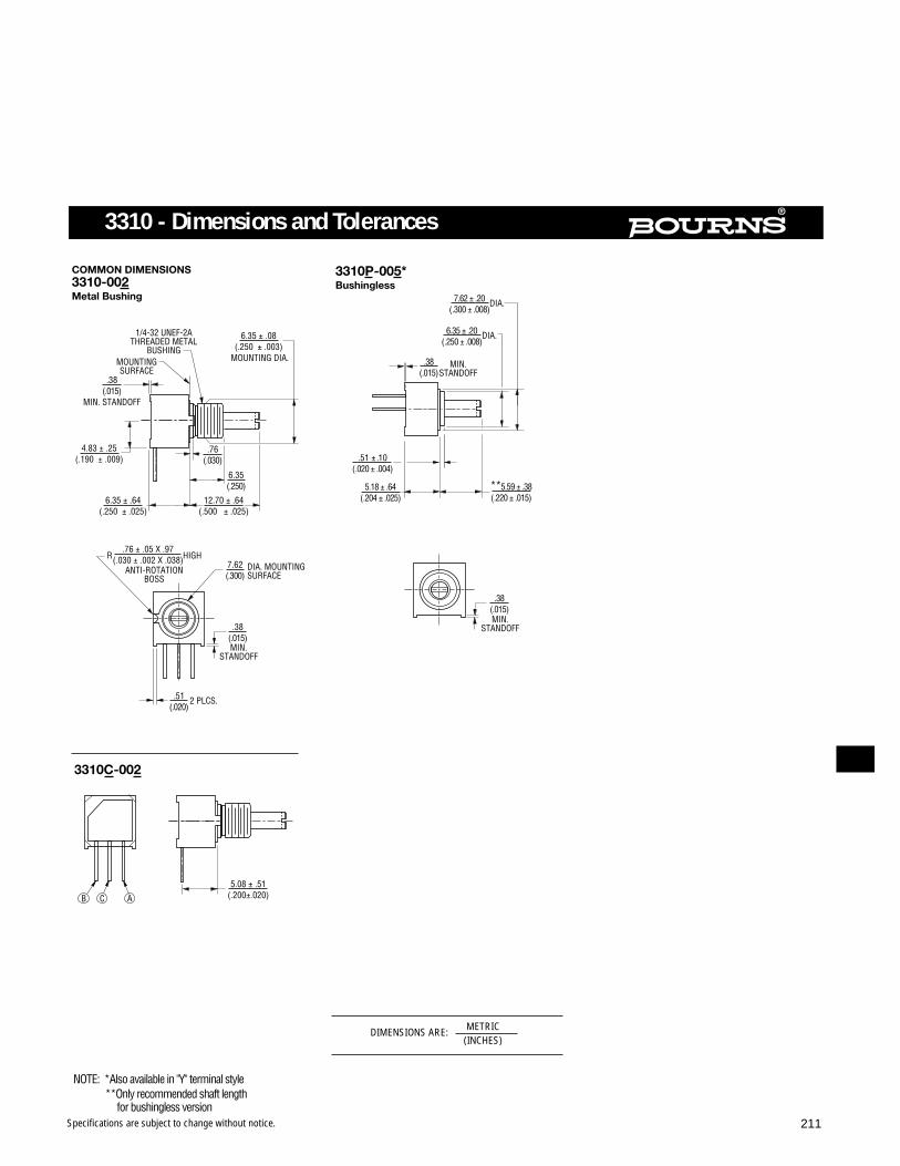
Specifications are subject to change without notice. 211
3310 - Dimensions and Tolerances
DIMENSIONS ARE: METRIC(INCHES)

Specifications are subject to change without notice.212
3310 - Dimensions and Tolerances
DIMENSIONS ARE: METRIC(INCHES)

Specifications are subject to change without notice. 213
3370 - 6mm Square Sealed Panel Control
Features Conductive plastic Linear and audio tapers PC board and bushing mount Plastic bushing and plastic shaft Withstands typical industrial washing
processes
Electrical CharacteristicsStandard Resistance Range
Linear.................................................................................................................................................................................................1K ohms to 1 megohmTotal Resistance Tolerance
Linear Tapers ................................................................................................................................................................................................................±20%Independent Linearity.........................................................................................................................................................................................................±5%Absolute Minimum Resistance......................................................................................................................................................................2 ohms maximumEffective Electrical Angle.......................................................................................................................................................................................240° nominalContact Resistance Variation.............................................................................................................................................1 ohm or 1% (whichever is greater)Dielectric Withstanding Voltage
Sea Level ..................................................................................................................................................................................................900 VAC minimum70,000 Feet...............................................................................................................................................................................................350 VAC minimum
Insulation Resistance .......................................................................................................................................................................1,000 megohms minimumPower Rating @ 70°C (Derate to 0 at 125°C - Voltage Limited By Power Dissipation or 200 VAC, Whichever is Less) ........................................... .25 watts
Environmental CharacteristicsStorage Temperature ......................................................................................................................................................................................-55°C to +125°CTCR (Over Storage Temperature Range)............................................................................................................................................................±1,000ppm/°CVibration ..............................................................................................................................................................................................................................30G
Total Resistance Shift ....................................................................................................................................................................................±2% maximumVoltage Ratio Shift .........................................................................................................................................................................................±2% maximum
Shock ................................................................................................................................................................................................................................100GTotal Resistance Shift ....................................................................................................................................................................................±2% maximumVoltage Ratio Shift .........................................................................................................................................................................................±2% maximum
Load Life (1,000 Hours) ...........................................................................................................................................................................±10% TRS maximumRotational Life-No Load (50,000 Cycles)...................................................................................................................................................±5% TRS maximumCRV ....................................................................................................................................................................................3 ohms or 3% whichever is greaterMoisture Resistance .................................................................................................................................................................................................±10% TRS
Mechanical CharacteristicsStop Strength .............................................................................................................................................................................................................5.65 NcmMechanical Angle..................................................................................................................................................................................................310° nominalTorque
Starting ..........................................................................................................................................................................................................1.41 Ncm Max.Weight ........................................................................................................................................................................................................................4.5 gramsFlammability ............................................................................................................................................................................................Conforms to UL94V-0Epoxy ......................................................................................................................................................................................................Conforms to UL94V-1Terminals ...........................................................................................................................................................................................................Solderable pinsMarking ................................................................Manufacturer’s symbol and model number, product code, terminal style, date code and resistance code
Standard Resistance Table
Resistance Resistance(Ohms) Code
1,000 1022,000 2025,000 502
10,000 10320,000 20350,000 503
100,000 104200,000 204500,000 504
1,000,000 105
Popular values listed in boldface. Consult factory for special resistances.
Part Numbering System
3370 Y - 0 0 1 - 103Model Number Designator
3370 = 6mm Panel Control
Terminal Style DesignatorSingle Cup:C = In-line Straight Terminals Side ExitP = 5.08mm x 2.54mm Triangular Pattern Rear ExitY = 5.08mm x 5.08mmTriangular Pattern Rear Exit
Shaft End Designator0 = Shaft End Slotted
Shaft Length Designator0 = 12.7mm FMS Long Plastic Shaft
Bushing Designator1 = 6.35mm x 6.35mm Plastic
Resistance Code(1st 2 digits are significant, 3rd digit is number of 0s to follow)

Specifications are subject to change without notice.214
3370 - Dimensions and Tolerances
DIMENSIONS ARE: METRIC(INCHES)

50 Series - Sealed 1/2” (12.5mm) Square Control
Specifications are subject to change without notice. 215
Features Conductive plastic or cermet Linear and audio tapers PC board and bushing mount Gangable Metal bushing and shaft Sealed for board washing
Electrical Characteristics1 Conductive Plastic CermetStandard Resistance Range
Linear..............................................................1K ohms to 1 megohm....................................150 ohms to 1 megohmAudio ..............................................................1K ohms to 1 megohm....................................1K ohms to 1 megohm
Total Resistance ToleranceLinear Tapers ..................................................±10% OR ±20%..............................................±10% OR ±5%Audio Tapers ..................................................±10% OR ±20%..............................................±10%
Independent Linearity .......................................±5%.................................................................±5%Absolute Minimum Resistance .........................2 ohms maximum............................................2 ohms maximumEffective Electrical Angle ..................................270°±5° ...........................................................270°±5°Contact Resistance Variation............................2.0%................................................................2.0%Dielectric Withstanding Voltage
Sea Level........................................................1,500 VAC minimum........................................1,500 VAC minimum70,000 ............................................................500 VAC minimum...........................................500 VAC minimum
Insulation Resistance........................................1,000 megohms minimum...............................1,000 megohms minimumPower Rating At 70°C (Derate To 0 At 125°C) (Voltage Limited By Power Dissipation or 350 VAC, Whichever Is Less)
Linear Tapers ..................................................0.5 watt ...........................................................1.0 wattAudio Tapers ..................................................0.25 watt .........................................................0.5 watt
Tracking (Multiple Sections) ..............................3 db .................................................................3 db
Environmental Characteristics1
Operating Temperature..........................................+1°C to +125°C ...................................................+1°C to +125°CStorage Temperature ........................................-55°C to +125°C .............................................-55°C to +125°CTCR (Over Storage Temperature Range) ..........±1,000ppm/°C.................................................±150ppm/°CVibration (Single Section)..................................15G..................................................................15G
Total Resistance Shift.....................................±2% maximum................................................±2% maximumVoltage Ratio Shift..........................................±5% maximum................................................±5% maximum
Shock (Single Section)......................................30G..................................................................30GTotal Resistance Shift.....................................+2% maximum................................................±2% maximumVoltage Ratio Shift..........................................±5% maximum................................................±5% maximumLoad Life (1,000 Hours) ..................................±10% TRS maximum......................................±5% TRS maximum
Rotational Life-No Load (50,000 Cycles)2 ........±10% TRS maximum......................................±10% TRS maximumCRV @ 25,000 Cycles .......................................±2%.................................................................±4%Moisture Resistance .........................................±10% TRS.......................................................±5% TRS
Mechanical CharacteristicsStop Strength....................................................5 in-lb. .............................................................5 in-lb.Mechanical Angle..............................................290° ±5° ..........................................................290° ±5°Torque
Running (Single Section) ................................0.2 to 2.0 oz.-in. (0.15 to 1.4Ncm) ..................0.2 to 2.0 oz.-in. (0.15 to 1.4 Ncm)Running (Dual or Triple Section) .....................0.5 to 2.5 oz.-in. (0.35 to 1.8 Ncm) .................0.5 to 2.5 oz.-in. (0.35 to 1.8 Ncm)Starting (All Sections) .....................................Running torque +0.5 oz.-in. ...........................Running torque +0.5 oz.-in.
(+0.35 Ncm) maximum (+0.35 Ncm) maximumWeight (Single Section) .....................................5.5 grams ........................................................5.5 grams
Each Additional Section .................................3.0 grams ........................................................3.0 gramsTerminals...........................................................PC pin or solder lug ........................................PC pin or solder lugMarking .............................................................Manufacturer’s symbol and part number, date code and resistance value
1At room ambient: +25°C nominal and 50% relative humidity nominal, except as noted.2Conductive Plastic, 25,000 cycles for cermet elements.

Specifications are subject to change without notice.216
3 2 1
(SINGLE, DUAL AND TRIPLE MODULE SHOWN)AVAILABLE IN 1 THROUGH 6 MODULE VERSIONS.
AVAILABLE IN 1 THROUGH 6 MODULE VERSIONS.
PACKAGE DIMENSIONS PCB MOUNTING BRACKET
PACKAGE DIMENSIONS
SOLDER LUG TERMINALS
ELECTRICAL SCHEMATIC
1 3 CWCCW
2
ANTI-ROTATION LUG(Style "A", 90° CW Shown)
0.41(.016)
BUSHING DIAMETER± 0.80
(± .031)
2.20(.087)
FOR TOLERANCES SHOWN: .XX = ± (.010)
.XXX = ± (.005)
SHAFT DIMENSIONS ±
(1/32)
5.70(.224)
132° ± 5° CCW END
6.20(.244)
BUSHING DIAMETER± 0.80
(± .031)
2.77(.109)
6.35(.250)
SHAFT FLATORIENTATION
SUGGESTED PANEL LAYOUTSThe Model 50 can be used with eitherof the two panel layouts shown below.
24.35 ± 0.33(.959 ± .013)
16.76 ± 0.25(.660 ± .010) 8.89 ± 0.18
(.350 ±.007)± .64
(± .025)"L"
0.30(.0118) 5.08 ± 0.30
(.200 ± .012)7.62 ± 0.30
(.300 ± .012)7.62 ± 0.30(.300 ± .012)
12.5(.492)
11.00(.432) DIA.
0.74(.029)
6.25(.246)
7.00(.275)
6.35 ± 0.25(.250 ± .010)
.66 ± .05 (.026 + .002)
3 X2.54
(.100)2.54
(.100)
12.5(.492)
6.25(.246)
7.00(.275)
6.35 ± 0.25(.250 ± .010)
11.00(.432) DIA.
0.74(.029)
.66 ± .05 (.026 + .002)
3 X
5.08(.200)
5.08(.200)
24.13 ± 0.33(.950 ± .013) ± .64
(± .025)"L"
.200 ± .012(5.08 ± 0.30)
7.62 ± 0.30(.300 ± .012)
0.91 ± 0.51(.036 ± .002)
6.35 ± .25(.250 ± .010)
.300 ± .012(7.62 ± 0.30)
.052 ± .010(1.32 ± 0.25)
12.5(.492)
11.00(.432) DIA.
0.74(.029)
6.25(.246)
7.00(.275)
6.35 ± 0.25(.250 ± .010)
.41 ± .05( .016 ± .002)
2 X
5.08(.200)
5.08(.200)
2.40(.094)
0.90(.036)
4.70(.185)2 X
1.80(.071)
5.0 ± 0.51(.197 ± .002)
0.80 ± 0.30(.031 ± .012) 1.52
(.060)
.25
.13
.80
( .100)TERMINAL SPACING2.54
(.200) TERMINAL SPACING5.08
50 Series - Dimensions and Tolerances
DIMENSIONS ARE: METRIC(INCHES)

Specifications are subject to change without notice. 217
OPT.
3/8-32UNEF-2A
1/4-32UNEF-2A
3/8-32UNEF-2A
1/4-32UNEF-2A
M6 X .075-6g
M7 X .075-6g
M10 X 0.75-6g
9.53(.375) 1.60 ± 0.25
(.063 ± .010)
OPT.1.194 ± 0.10(.047 ± .004)
SHAFT6.35
(.250) BUSHING9.53
(.375)
OPT.6.35
(.250) 0.79 ± 0.25(.031 ± .010)
OPT.0.79 ± 0.10
(.031 ± .004)
SHAFT3.18
(.125) BUSHING6.35
(.250)
OPT.
9.53(.375)
1.52 ± 0.25(.060 ± .010)
OPT.5.49 ± 0.10
(.216 ± .005)
SHAFT6.35
(.250) BUSHING9.53
(.375)
MAX. FLAT LENGTH15.88(.625)
OPT.
12.70(.500) 0.79 ± 0.25
(.031 ± .010)
OPT..031 ± .004
(0.79 ± 0.10)
SHAFT.125
(3.18) BUSHING.250
(6.35)
.315(8.0) .060 ± .010
(1.52 ± 0.25)
0.79 ± 0.10(.031 ± .004)
SHAFT3.0
(.118) BUSHING6.0
(2.36)
8.0(.315)
1.52 ± 0.25(.060 ± .010)
0.79 ± 0.10(.031 ± .004)
SHAFT4.0
(.157) BUSHING7.0
(2.75)
9.5(.374) 1.80 ± 0.25
(.071 ± .010)
1.00 ± 0.10(.039 ± .004)
SHAFT6.0
(.236) BUSHING10.0
(.394)
A Style Bushing
STD. LENGTH ‘L’.500 (12.7).625 (15.88).750 (19.05).875 (22.23)1.000 (25.4)
C Style Bushing
STD. LENGTH ‘L’.375 (9.53).500 (12.7).625 (15.88).750 (19.05).875 (22.23)1.000 (25.4)
F Style Bushing
STD. LENGTH ‘L’.625 (15.88).750 (19.05).875 (22.23)1.000 (25.4)
S Style Bushing
STD. LENGTH ‘L’.394 (10.0).512 (13.0).630 (16.0).866 (22.0).984 (25.0)
U Style Bushing
STD. LENGTH ‘L’.394 (10.0).512 (13.0).630 (16.0).866 (22.0).984 (25.0)
R Style Bushing
STD. LENGTH ‘L’.512 (13.0).630 (16.0).866 (22.0).984 (25.0)
A Style Bushing -Flatted Shaft
STD. LENGTH ‘L’.625 (15.88).750 (19.05).875 (22.23)1.000 (25.4)
51 A A D - B 28 - A 15
MOUNTING BRACKET/ANTI-ROTATION LUG
Code DescriptionA AR Lug 90°CWD No AR Lug or Bracket
How To Order
# SECTIONS/DETENTSCode Description
A Single No DetentB Double No Detent
BUSHING CONFIGURATIONCode Description
A 3/8”D x 3/8”LC 1/4”D x 1/4”LR 10mmD x 9.5mmLS 6mmD x 8mmLU 7mmD x 8mmL
MODELCode Description
51 PC Pins (.100” centers)53 Solder Lugs
AVAILABLE ONLY INSHAFT TYPE BUSHINGS LENGTHS
Code Description Code DescriptionB Single Slotted 1/4”D A 24,28E Single Slotted 1/8”D C, F 24,28R Single Slotted 6mmD R 25T Single Slotted 4mmD U 25U Single Slotted 3mmD S 16
ELEMENT TAPER RESISTANCETYPE/TOLERANCE (CODE)
Code Description VALUE IN OHMS
(A) Linear Cermet ±10% (10) — 1K (18) — 50K(B) Linear C-P ±20% (13) — 5K (20) — 100K(D) CW Audio C-P (15) — 10K
±20%
SHAFT AVAILABLELENGTH ONLY IN
(FMS) BUSHINGCode Description Code
24 3/4” A, C, F28 7/8” A, C, F
Metric16 16mm R, S, U, T25 25mm R, S, U, T
(Recommended standard P/N’s)For Other Options Contact the Factory
Boldface listings are in stock and readily availablethrough distribution.
50 Series- Dimensions and Tolerances
Shaft/Bushing Styles
DIMENSIONS ARE: METRIC(INCHES)

Specifications are subject to change without notice.218
81/82 - 5/8” Square Single-Turn Conductive Plastic
Initial Electrical Characteristics1 Conductive Plastic Element Cermet ElementStandard Resistance Range
Linear Tapers (A, B, E, & H)......................................(B & E) 1K ohms to 1 megohm..................................(A & H) 50 ohms to 1 megohmAudio Tapers (C, D, F, G, S, & T) .............................(D, G, S, & T) 1K ohms to 1 megohm........................(C & F) 1K ohms to 1 megohm
Resistance Tolerance..................................................(B, D,& G tapers) ±20% ............................................(A, C, & F tapers) ±10%(E, S, & T tapers) ±10% (H taper) ±5%
Independent Linearity .................................................(B & E tapers) ±5% ...................................................(A & H tapers) ±5%Absolute Minimum Resistance ...................................2 ohms maximum .....................................................2 ohms maximumContinuity....................................................................Maintained for full mechanical angle ........................Maintained for full mechanical angleEffective Electrical Angle ............................................240° ±5%..................................................................240° ±6°Contact Resistance Variation......................................±1% ..........................................................................±1% or 3 ohms (whichever is greater)Theoretical Resolution ................................................Essentially infinite......................................................Essentially infiniteDielectric Withstanding Voltage..................................MIL-STD-202, Method 301.......................................MIL-STD-202, Method 301
Sea Level .................................................................1,500 VAC minimum .................................................1,500 VAC minimum70,000 Feet ..............................................................500 VAC minimum ....................................................500 VAC minimum
Insulation Resistance (500 VDC).................................1,000 megohms minimum ........................................1,000 megohms minimumPower Rating At 70°C (Voltage Limited By Power Dissipation or 350 VAC, Whichever Is Less)
+70°C Single Section Assembly ..............................(B & E tapers) 0.5 watt ..............................................(A & H tapers) 2 watts(D, G, S & T tapers) 0.25 watt (C & F tapers) 1 watt
+70°C Multiple Section Assembly ...........................(B & E tapers) 0.5 watt/section .................................(A & H tapers) 1 watt/section(D, G, S & T tapers) 0.25 watt/section (C & F tapers) 0.5 watt/section
+125°C.....................................................................0 watt ........................................................................0 wattRoll-on/Roll-off............................................................(B & E tapers) 0.25% maximum................................(A & H tapers) 0.5% maximum
(D & S tapers) 0.1% maximum CCW end (C taper) 0.1% maximum CCW end(G & T tapers) 0.1% maximum CW end (F taper) 0.1% maximum CW end(D & S tapers) 0.5% maximum CW end (C taper) 1.0% maximum CW end(G & T tapers) 0.5% maximum CCW end (F taper) 1.0% maximum CCW end
Environmental Characteristics1
Operating Temperature..........................................+1°C to +125°C ...................................................+1°C to +125°CStorage Temperature Range.......................................-55°C to +125°C .......................................................-55°C to +125°CTemperature Coefficient
Over Storage Temperature Range ...........................±1,000PPM/°C..........................................................±150PPM/°CVibration (Single Section)............................................15G ...........................................................................15G
Voltage Ratio Shift ...................................................±5% maximum .........................................................±5% maximumTotal Resistance Shift ..............................................±2% maximum .........................................................±2% maximum
Shock (Single Section)................................................30G ...........................................................................30GVoltage Ratio Shift ...................................................±5% maximum .........................................................±5% maximumTotal Resistance Shift ..............................................±2% maximum .........................................................±2% maximum
Load Life .....................................................................1,000 hours ...............................................................1,000 hoursTotal Resistance Shift ..............................................±10% maximum .......................................................±5% maximum
Rotational Life (No Load) ............................................100,000 cycles..........................................................100,000 cyclesTotal Resistance Shift ..............................................(B & E tapers) 10 ohms or ±12% maximum ............10 ohms or ±10% maximum
(whichever is greater) (whichever is greater)(D, G, S & T tapers) ±20% maximum
Moisture Resistance ...................................................MIL-STD-202, Method 103, Condition B..................MIL-STD-202, Method 103, Condition BTotal Resistance Shift ..............................................(B & E tapers) ±10% maximum ................................±5% maximum (all tapers)
(D, G, S & T tapers) ±20% maximumInsulation Resistance (500 VDC)..............................100 megohms minimum ...........................................100 megohms minimum
Mechanical Characteristics1
Running Torque (Non-Locking Bushings)Single Section ..........................................................0.2 to 1.5 oz.-in. (0.14 to 1.06 Ncm) .........................0.2 to 1.5 oz.-in. (0.14 to 1.06 Ncm)Dual Section.............................................................0.2 to 1.5 oz.-in. (0.14 to 1.06 Ncm) .........................0.2 to 1.5 oz.-in. (0.14 to 1.06 Ncm)Triple Section ...........................................................0.5 to 2.0 oz.-in. (0.35 to 1.41 Ncm) .........................0.5 to 2.0 oz.-in. (0.35 to 1.41 Ncm)Quadruple Section ...................................................0.5 to 2.0 oz.-in. (0.35 to 1.41 Ncm) .........................0.5 to 2.0 oz.-in. (0.35 to 1.41 Ncm)
Running Torque (Locking Bushings) ...........................0.2 to 4.0 oz.-in. (0.14 to 2.82 Ncm) .........................0.2 to 4.0 oz.-in. (0.14 to 2.82 Ncm)Shaft Locking Torque with Locknut
@ 10 in-lb. (B & E Bushings) ....................................20 oz-in. ....................................................................20 oz-in.Stop Strength..............................................................1/4” (6.35mm) and 1/8” (3.18mm) shafts - ...............1/4” (6.35mm) and 1/8” (3.18mm) shafts -
4 in.-lb. (45.19 Ncm) min. 4 in.-lb. (45.19 Ncm) min.7/8” (19.81mm) shaft -2 in.-lb. ( 22.6 Ncm) min. 7/8” (19.81mm) shaft -2 in.-lb. ( 22.6 Ncm) min.
Mechanical Angle .......................................................300° ±5° ....................................................................300° ±5°Weight (Single Section) ...............................................21 grams maximum ..................................................21 grams maximum
Each Additional Section...........................................6 grams maximum ....................................................6 grams maximumTerminals.....................................................................Printed circuit terminals or J-Hooks .........................Printed circuit terminals or J-HooksMarking .......................................................................Manufacturer’s trademark, wiring diagram, date code and resistance, manufacturer’s part number
NOTE: Model 81/82 performance specifications do not apply to units subjected to printed circuit board cleaning procedures.1At room ambient: +25°C nominal and 50% relative humidity nominal, except as noted.
Features Metal shaft and bushing Consistent, smooth quality feel Up to 4 sections available
For dimensional drawings see page 222.For ordering information see page 224.

Specifications are subject to change without notice. 219
83/84 - 5/8” Square 10-Turn
Wirewound Element (J Taper) Hybriton® Element (K Taper)
Standard Resistance Range .......................................200 to 100K ohms.....................................................1K to 100K ohmsResistance Tolerance..................................................±5% ..........................................................................±10%Independent Linearity .................................................±0.25% .....................................................................±0.25%Effective Electrical Angle ............................................3600° +10°, -0° .........................................................3600° +10°, -0°Minimum Resistance (J Taper)....................................1.0 ohm or 0.1% (whichever is greater) ....................–End Voltage (K Taper)..................................................– ................................................................................0.2% of applied voltageNoise (J Taper) ............................................................100 ohms ENR maximum .........................................–Output Smoothness (K Taper) ....................................– ................................................................................0.15% maximumDielectric Withstanding Voltage..................................MIL-STD-202, Method 301.......................................MIL-STD-202, Method 301
Sea Level .................................................................1,500 VAC minimum .................................................1,500 VAC minimumInsulation Resistance (500 VDC).................................1,000 megohms minimum ........................................1,000 megohms minimumPower Rating (Voltage Limited By Power Dissipation or 316 VAC, Whichever Is Less)
+70°C ......................................................................1 watt ........................................................................1 watts+125°C.....................................................................0 watt ........................................................................0 watt
Theoretical Resolution ................................................See table ...................................................................Essentially infinite
Environmental Characteristics1
Operating Temperature..........................................+1°C to +125°C ...................................................+1°C to +125°CStorage Temperature Range.......................................-55°C to +125°C .......................................................-55°C to +125°CTemperature CoefficientOver Storage Temperature Range ..............................±50PPM/°C...............................................................±100PPM/°CVibration......................................................................15G ...........................................................................15G
Wiper Bounce ..........................................................0.1 millisecond maximum .........................................0.1 millisecond maximumShock..........................................................................50G ...........................................................................50G
Wiper Bounce ..........................................................0.1 millisecond maximum .........................................0.1 millisecond maximumLoad Life .....................................................................1,000 hours ...............................................................1,000 hours
Total Resistance Shift ..............................................±2% maximum .........................................................±5% maximumRotational Life (No Load) ............................................1,000,000 shaft revolutions.......................................4,000,000 shaft revolutions
Total Resistance Shift ..............................................±5% maximum ........................................................±5% maximum Moisture Resistance ...................................................MIL-STD-202, Method 103, Condition B..................MIL-STD-202, Method 103, Condition B
Total Resistance Shift ..............................................±2% maximum ........................................................±5% maximumInsulation Resistance (500 VDC)..............................100 megohms minimum ...........................................100 megohms minimum
Mechanical Characteristics1
Mechanical Angle .......................................................3600° +15°, -0° .........................................................3600° +15°, -0°Shaft Runout...............................................................0.006 in. (0.15mm) T.I.R. ...........................................0.006 in. (0.15mm) T.I.R.Shaft End Play ............................................................0.014 in. (0.36mm) T.I.R. ...........................................0.014 in. (0.36mm) T.I.R.Shaft Radial Play.........................................................0.005 in. (0.13mm) T.I.R. ...........................................0.005 in. (0.13mm) T.I.R.Stop Strength..............................................................48.0 oz.-in. (33.90 Ncm) minimum............................48.0 oz.-in. (33.90 Ncm) minimumRunning Torque (1 or 2 Section) .................................0.25 to 2.0 oz.-in. (0.18 to 1.41 Ncm) .......................0.25 to 2.0 oz.-in. (0.18 to 1.41 Ncm)Weight ........................................................................Approximately 0.75 oz.-in. (0.53 Ncm) .....................Approximately 0.75 oz.-in. (0.53 Ncm)Terminals.....................................................................Printed circuit terminals or solder lugs .....................Printed circuit terminals or solder lugsMarking .......................................................................Manufacturer’s trademark, wiring diagram, ..............Manufacturer’s trademark, wiring diagram,
date code and resistance, manufacturer’s date code and resistance, manufacturer’s part number part number
NOTE: MODEL 83/84 PERFORMANCE SPECIFICATIONS DO NOT APPLY TO UNITS SUBJECTED TO PRINTED CIRCUITBOARD CLEANING PROCEDURES.1AT ROOM AMBIENT: +25°C NOMINAL AND 50% RELATIVE HUMIDITY NOMINAL, EXCEPT AS NOTED.
Resistance Resolution(Ohms) (Nom.) (%)
200 .048500 .0371K .0322K .0315K .02310K .02020K .01550K .012
100K .010
Wirewound Resolution Table
37.03 ± .71(1.458 ± .028)
Dual Section Model 83 PC Pins
7.62 ± .25(.30 ± .01)
Note: The Models 83/84 dimensions for dualsection assembly are for either single or dualconcentric shaft styles.
Dual Section Model 84 Solder Lugs
37.03 ± .71(1.458 ± .028)
7.62 ± .25(.30 ± .01)
Dimensional Drawings
Features Compatible with other members of the
Model 80 Series The only 10-turn precision potentiometer
in a modular panel control package Up to 3 sections available
Initial Electrical Characteristics1
For dimensional drawings see page 220 and 223.For ordering information see page 22214.
DIMENSIONS ARE: METRIC(INCHES)

Specifications are subject to change without notice.220
1 3
2
1 3 CWCCW
2 WIPER
CLOCKWISE
Locating Lug Options - All Model 80 Series
A.46
(.018)
NOTE: "D" OPTION - NO A/R LUG. OTHER LOCATING LUG OPTIONS AVAILABLE. FOR DETAILS CONSULT FACTORY.
NOTE: SLOTTEDEND SHAFTORIENTATION ISRANDOM.
120° ± 5°STD. FLATORIENTATION(SHAFT ATCCW END)
Shaft Flat Orientation
PC Pin Model 83
.91(.036)
19.05 ± .51(.75 ± .02)
.79 ± .41(.031 ± .016)
1.27 ± 1.02(.50 ± .04)
2.54 ± .25(.10 ± .01)
7.62 ± .25(.30 ± .01)
(.012) TYP. 3 PLCS..30
6.10 ± .51(.24 ± .02)
(FMS TO C )L
15.88 ± .38(.625 ± .015)
15.88 ± .38(.625 ± .015)
1.52(.06)
5.08 ± .51(.20 ± .02)
9.14 ± .76(.36 ± .03)
Solder Lug Model 84
19.05 ± .51(.75 ± .02)
6.79 ± .41(.031 ± .01)
(FMS TO C )L6.10 ± .51(.24 ± .02)
5.59 ± .51(.22 ± .02)
2.54 ± .25(.10 ± .01)
TYP. 3 PLCS..30(.012)
7.62 ± .25(.30 ± .01)
15.88 ± .38(.625 ± .015)
15.88 ± .38(.625 ± .015)
1.52(.06)
9.14 ± .76(.360 ± .03)
(.040)
SLOT1.02 WIDE X 2.29 LONG
TYP.(.090) .140 ± .02
(3.56 ± .51)
1.78 ± .25(.070 ± .010)
2.03 ± .13(.080 ± .005)
1/4-32 UNEF
"E" Bushing1/4" (6.35mm) Dia. Locking - Single Shaft
6.35 ± .13(.500 ± .005)
10.80(.425)MIN.
6.35 ± .05(.250 ± .002)PILOT DIA.
15.90 ± 0.80(5/8 ± 1/32)STANDARD
SHAFT SLOT.031 WIDE X .78 ± .25 DEEP(.78) (.031) (.010)
45° X (.010)CHAMFER
.25
3.162 ± .025(.1245 ± .001) DIA.
3/8-32 UNEFTRIPLE CONCENTRIC(SPECIAL ORDER)
"A" Bushing3/8" (9.53mm) Dia. Plain - Concentric Shaft
28.58 ± .79(1.125 ± .031) STANDARD
9.53(.375)
19.05 ± .79(3/4 ± 1/32)STANDARD
6.32 ± .03(.249 ± .001)
DIA.
3.162 ± .025(.1245 ± .001)
DIA.
DIA.1.98 ± .03(.078 ± .001)
OUTER SHAFT 6.32 DIA. OPERATES SECTION #1 INNER SHAFT 3.18
DIA. OPERATES SECTION #2, #3, & #4 ("G" STYLE)(.249) (.125)
"B" Bushing3/8" (9.53mm) Dia. Plain - Single Shaft
3/8-32 UNEF
12.70 ± .13(.500 ± .005)
15.88 ± .79(5/8 ± 1/32)STANDARD
SHAFT SLOT 1.19 WIDE X
1.60 + .38/-.00 DEEP(.047)
(.063 + .015/-.000)
45° X (.010)CHAMFER
.25
6.32 ± .03(.249 ± .001) DIA.
9.53 ± .13(.375 ± .005)PILOT DIA.
11.13(.438)MIN.
7.75(.305)
2.31(.091)
E
3.18(.125)
13.50(.531)
J
2.36(.093)
9.53(.375)
H
3.18(.125)
11.10(.437)
.79 ± .41(.031 ± .016)
TOLERANCES EXCEPT AS SHOWN: DECIMALS .XXX ± .127(.005)
.XX± .38(.015)
ANGLE ± 5°FRACTIONS ± 1/64
"C" Bushing1/4" (6.35mm) Dia. Plain - Single Shaft
6.35 ± .13(.250 ± .005)
9.53,12.7,15.88,19.05,22.23 ± .79(3/8, 1/2, 5/8, 3/4, 7/8, ± 1/32)
STANDARD3.162 ± .025
(.1245 ± .001)DIA.
45° X (.010)CHAMFER
.25
SHAFT SLOT .79 WIDE X .79
.25 DEEP
(.031) (.031)
(±.010)6.35 ± .05
(.250 ± .002)PILOT DIA.
2.39 OPTIONAL FLAT .250 LONG OR .06 FROM
"C" BUSHING END FOR SHAFTS UNDER 9/16(.094) (6.35) (1.52)
(14.30)
4.45(.175)MIN.
"A" Bushing3/8" (9.53mm) Dia. Plain - Single Shaft
3/8-32 UNEF9.50 ± 0.40(.375 ± .15)
12.7,15.88,19.05,22.23± .79(1/2, 5/8, 3/4, 7/8 ± 1/32)
STANDARD6.32 ± .03
(.249 ± .001)DIA.
7.92(.312)MIN. 9.53 ± .13
(.375 ± .005)PILOT DIA.
45° X (.010)CHAMFER
.25 (.063+.015/-.000)
SHAFT SLOT 1.19 WIDE X
1.60 + .38/-.00 DEEP
(.047)
5.49 OPTIONAL FLAT 16.00 LONG OR 1.52 FROM
A" BUSHING END FOR SHAFTS UNDER (11/16)(.216 ) (.63) (.06)17.66
"C" Bushing1/4" (6.35mm) Dia. Plain - Concentric Shaft
1/4-32 UNEF
25.40 ± .79(1 ± 1/32) STANDARD
15.88 ± .79(5/8 ± 1/32)STANDARD
6.35(.25)
OUTER SHAFT 3.18 DIA.OPERATES SECTION #1 INNER SHAFT 1.98
DIA. OPERATES SECTION #2, #3, & #4 ("K" STYLE)(.125)
(.08)
3.162 ± .025(1.245 ±.001) DIA.
DIA..078 ± .001(1.98 ± .03)
83/84 - Dimensions and Tolerances
DIMENSIONS ARE: METRIC(INCHES)

Specifications are subject to change without notice. 221
85/86 - 5/8” Square Single-Turn Rotary Switch
For Dimensional Drawings See Page 223.For Ordering Information See Page 224.
Initial Electrical Characteristics1
Contacts:DPST....................................................................................................................................................................N.O/N.O.,N.C./N.C. or N.O./N.C.DPDT ....................................................................................................................................................................2 N.O./N.C. (break before make)
Power Rating (Resistive Load):DPST ...................................................................................................2A @ 125 volts RMS-60 Hz or 2A @ 28 VDC, 1aA@ 250 volts RMS-60 HzDPDT..................................................................................................................................................1A @ 125 volts RMS-60 Hz or 1A @ 28 VDC
Contact Resistance (.1VDC-10mA)...........................................................................................................................................10 milliohms nominalContact Bounce ..................................................................................................................................................................5 milliseconds maximumDielectric Withstanding Voltage.......................................................................................................................................MIL-STD-202, Method 301
Sea Level ..................................................................................................................................................................................1500 VAC minimumInsulation Resistance .........................................................................................................................................................1000 megohms minimum
Environmental Characteristics1
Operating Temperature Range ..............................................................................................................................................................0°C to +70°CStorage Temperature Range...............................................................................................................................................................-65° to +125°CVibration (Dual Section)..........................................................................................................................................................................................8G
Contact Resistance.............................................................................................................................................................10 milliohms maximumContact Bounce ..............................................................................................................................................................0.1 millisecond maximum
Shock (Dual Section)............................................................................................................................................................................................20GContact Resistance.............................................................................................................................................................10 milliohms maximumContact Bounce ..............................................................................................................................................................0.1 millisecond maximum
Rotational Life.......................................................................................................................................................................................25,000 cyclesSwitch Actuating Torque (50% Duty cycle @ Rated Power Load) ........................................................................2 to 7 oz.-in. (1.41 to 4.94 Ncm)Contact Resistance...........................................................................................................................................................100 milliohms maximum
Moisture Resistance ...................................................................................................................................MIL-STD-202, Method 106, Condition BContact Resistance (0.1VDC-10mA)...................................................................................................................................10 milliohms maximumInsulation Resistance (After 24 Hours @ Room Temperature) (500 VDC) .........................................................................100 megohms minimum
Switch Housing Material ...................................................................................................High temperature, flame retardant, thermosetting plastic
Mechanical Characteristics1
Actuating Torque (Each Section, Switch Module Only) .........................................................................................5 to 15 oz.-in. (3.53 to 10.6 Ncm)Running Torque (Out of Detent, 2-4 Module Assembly) .......................................................................................0.3 to 2 oz.-in. (0.21 to 1.41 Ncm)Detent ......................................................................................................................................................................................CW or CCW standardActuation Angle .....................................................................................................................................................................................................25°Contact Materials ...........................................................................................................................................................Fine silver with gold overlayTerminal Styles....................................................................................................................................................................................Solder lug only
Standard Orientation...................................................................................................................................................In-line with control terminalsOptional ...............................................................................................................................................................Rotated 90° CCW from standard
Terminal Strength (Before and After Soldering Heat Exposure)............................................................................................2 lbs. (0.9 Kg) minimum
NOTE: MODEL 85/86 PERFORMANCE SPECIFICATIONS DO NOT APPLY TO UNITS SUBJECTED TO PRINTED CIRCUIT BOARD CLEANING PROCEDURES.1AT ROOM AMBIENT: +25°C NOMINAL AND 50% RELATIVE HUMIDITY NOMINAL, EXCEPT AS NOTED.
Features Designed for “on-off” function control Positive action, “non-tease” detent Low actuation torque

Specifications are subject to change without notice.222
Model 81, 82 - Dimensions and Tolerances
DIMENSIONS ARE: METRIC(INCHES)
"A" Bushing3/8" (9.53mm) Dia. Plain - Single Shaft
3/8-32 UNEF
"B" Bushing3/8" (9.53mm) Dia. Plain - Single Shaft
3/8-32 UNEF4.45
(.175)MIN.
"C" Bushing1/4" (6.35mm) Dia. Plain - Single Shaft
"C" Bushing1/4" (6.35mm) Dia. Plain - Concentric Shaft
3/8-32 UNEFTRIPLE CONCENTRIC(SPECIAL ORDER) 1/4-32 UNEF
"A" Bushing3/8" (9.53mm) Dia. Plain - Concentric Shaft
1/4-32 UNEF
"E" Bushing1/4" (6.35mm) Dia. Locking - Single Shaft
Dual Unit - PC Pins & J-Hook Triple Unit - PC Pins & J-Hook Quad Unit - PC Pins & J-Hook
FLATTED SHAFT
120° ± 5° CCW END
Shaft Flat Orientation*
SLOTTED SHAFT
30° ± 5°
*EXCLUDES MODELS 83 AND 84
Model 81Suggested PC Board Layout - PC Pins(Single-Shaft Style Bottom View)
Note: For units with dual concentric shaft styles, a.100 (2.54) spacer is added between the module(s) drivenby the outer shaft and those driven by the inner shaft.For G, K, or V shafts, add the spacer betweenmodules 1 and 2. For L or M shafts, add the spacerbetween modules 2 and 3. For N or P shafts, add thespacer between modules 3 and 4.
Model 81/82Single Unit - PC Pins & J-Hook
Terminal outlines shown as solid lines represent PC Pins, available on Model 81. Dashed line terminal outline represents "J" Hook, available on Model 82.
13
2
9.50 ± .38(.375 ±.015)
12.7,15.88,19.05,22.23± .79(1/2, 5/8, 7/8, ± 1/32)
STANDARD
DIA.
(.063+.015/-.000)
SHAFT SLOT 1.19 WIDE X
1.60+.38/-.00 DEEP
(.047)
45° X (.010)CHAMFER
.257.92
(.312)MIN.9.53 ± .13
(.375 ± .005)PILOT DIA.
5.49 ± .13 OPTIONAL FLAT 16.00 LONG OR 1.52 FROM
"A" BUSHING END FOR SHAFTS UNDER 17.46 (.216 ± .000) (.63) (.06)
(11/16)
45° X (.010)CHAMFER
.25
(.063 +.015/-.000)
SHAFT SLOT 1.19 WIDE X
1.60 + .38/- .00 DEEP
(.047)
12.70 ± .13(.500 ± .005)
15.88 ± .79(5/8 ± 1/32)STANDARD
6.32 ± .03(.249 ± .001) DIA.
9.53 ± .13(.375 ± .005)PILOT DIA.
11.13(.438)MIN.
6.35 ± .13(.250 ± .005)
9.53,12.7,15.88,19.05,22.23 ± .79(3/8, 1/2, 5/8, 3/4, 7/8, ± 1/32)
STANDARD
SHAFT SLOT .031 WIDE X
.031 ± .010 DEEP(.79)
(.79 ± .25)
45° X (.010)CHAMFER
.25
2.39 ± .13 OPTIONAL FLAT 6.35 LONG OR 1.52 FROM
"C" BUSHING END FOR SHAFTS UNDER 14.30 (.094 ± . 005) (.250) (.06)
(9/16)
6.35 ± .05(.250 ± .002)PILOT DIA.
45° X (.010)CHAMFER
.25
SHAFT SLOT .78 WIDE X
.78 ± .03 DEEP(.031)
(.031 ± .001)
12.7 ± .13(.500 ± .005)
10.80(.425)MIN.
15.88 ± .79(5/8 ± 1/32)STANDARD
3.18 ± .03(.125 ± .001) DIA.
6.35 ± .05(.250 ± .002)PILOT DIA.
28.58 ± .79(1-1/8 ± 1/32)
STANDARD19.05 ± .79(3/4 ± 1/32)STANDARD .375
(9.53)
6.32 ± .03(.249 ±.001)
DIA.
3.162 ± .025(.1245 ± .001)
DIA.
1.98 ± .03(.078 ± .001)DIA.
OUTER SHAFT 7.47 DIA. OPERATES SECTION #1 INNER SHAFT 3.18
DIA. OPERATES SECTION #2, #3, & #4 ("G" STYLE)
(.249)(.125)
OUTER SHAFT 3.18 DIA. OPERATES SECTION #1 INNER SHAFT .078
DIA. OPERATES SECTION #2, #3, & #4 ("G" STYLE)
(.125)(1.95)
15.88 ± .79(5/8 ± 1/32)STANDARD
25.40 ± .79(1 ± 1/32) STANDARD
6.35(.25)
3.162 ± .025(.1245 ± .001)DIA.
1.98 ± .03(.078 ± .001)DIA.
26.04 ± .79(1.025 ± .031)
10.16 ± .38(.400 ± .015)
10.16 ± .38(.400 ± .015)
TYP. 10.16 ± .38(.400 ± .015)
TYP.
36.20 ± 1.19(1.425 ± .047)
46.36 ± 1.19(1.825 ± .047)
15.88 ± .41(.625 ± .016)
5.97 ± .38(.235 ± .015)
5.08 ± .38(.200 ± .015)
15.88 ± .38(.625 ± .015) 11.94
(.470)
9.58 ± .38(.377 ± .015)
15.88 ± .38(.625 ± .015)
5.33 ± .76(.210 ± .03)
3.81(.150) MAX. 3 PLCS.
.81(.032)
DIA.
5.08 ± .38(.200 ± .015)
12.7(.50)
1.14(.045) DIA.5.08 ± .13
(.200 ± .005)
10.16 ± .13(.400 ± .005)
5.08 ± .13(.200 ± .005)
3.162 ± .025(.1245 ± .001)
DIA.6.32 ± .03
(5/8 ± 1/32)
1/4-32 UNEF

Specifications are subject to change without notice. 223
Model 83, 84, 85, 86 - Dimensions and Tolerances
DIMENSIONS ARE: METRIC(INCHES)
REARPLATECOVER
.725(18.42)
Switch ModuleModel 85/86
Primary Potentiometer ModuleModel 85/86
Secondary Potentiometer ModuleModel 85/86
Locating Lug Options - All Model 80 Series
REARCOVERPLATE
SWITCHMODULE
PRIMARYPOTENTIOMETER
MODULE
Assembly SequenceModel 85/86Secondary Potentiometer Module
Note: The Models 83/84 dimensions for dualsection assembly are for either single or dualconcentric shaft styles.
Dual Section Model 83 PC Pins
Dual Section Model 84 Solder Lugs
TOLERANCES EXCEPT AS SHOWN: DECIMAL .XXX ± (.005)
.XX ± (.015)
ANGLE ± 5%
Solder Lug Model 84Solder Lug Model 84
.91(.036)
1 3
2
1 3 CWCCW
2 WIPER
CLOCKWISE 1 3
2
19.05 ± .51(.75 ± .02)
.79 ± .41(.031 ± .016)
1.27 ± 1.02(.50 ± .02)
2.54 ± .25(.10 ± .01)
7.62 ± .25(.30 ± .01)
.30(.012) TYP. 3 PLCS.
L(FMS TO C )6.10 ± .51(.24 ± .02)
15.88 ± .38(.625 ± .015)
15.88 ± .38(.625 ± .015)
1.52(.06)
.08 ± .51(.20 ± .025)
9.14 ± .76(.36 ± .03)
19.05 ± .51(.75 ± .02)
5.59 ± .51(.22 ± .02)
.79 ± .41(.031 ± .016)
6.10 ± .51(.24 ± .02) L(FMS TO C )
7.62 ± .25(.30 ± .01)
.30(.012) TYP. 3 PLCS.
2.54 ± .25(.10 .01)
1.02 WIDE
X 2.29 LONG
(.04)
(.09)
15.88 ± .38(.625 ± .015)
15.88 ± .38(.625 ± .015)
1.52(.06)
2.03 (.080 )1.78 ± .25(.07 ± .01)
3.56 ± .51(.14 ± .02)
9.14 ± .76(.36 ± .03)
14.53(.572)
9.58 ± .38(.377 ± .015)
12.7(.50)
5.08(.200)
5.97(.235)
8.56(.337)
10.16(.400)
1.60(.063)
8.56(.337)
5.08(.200)
15.88(.625)
15.88(.625)
5.08(.200)
7.62 ± .25(.30 ± .01)
37.03 ± .71(1.458 ± .028)
1.35(.053)
2.77(.109)
TYP. 6 PLACES
2.29(.090)
(.095)L X (.045)W
SLOT TYP. 6 PLACES
2.41 1.14 2.92(.115)
9.53(.375)
37.03 ± .71(1.458 ± .028)
7.62 ± .25(.30 ± .01)
.127
.38
A7.75
(.305).46(.018)
2.31(.091)
E
3.18(.125)
13.49(.531)
J
2.36(.093)
9.53(.375)
H
3.18(.125)
11.10(.437)
.79 ± .41(.031 ± .016)
E = 2.36 ± .76(.093 ± .03)
H & J = 1.98 ± .41(.078 ± .016)
SLOT
TYP.

Specifications are subject to change without notice.224
ANTI-ROTATION LUGA Single .305R, 90°CWD No Lug
# SECTIONS APPLICABLE MODELS1 Single 81,82,83,84
AVAILABLE ONLY INSHAFT TYPE LENGTHS BUSHINGS
(CODE) (CODE)B Single Slotted 1/4” (6.35mm) D 16,20,24,28 A, B, JE Single Slotted 1/8” (3.18mm) D 12,16,20,24,28 C, E, NR Single Slotted 6mmD 16,19,22,50 R
ELEMENT TYPE RESISTANCE CODETAPER/TOLERANCE VALUE IN OHMS
MODELS 81, 82, 85 AND 86 ONLY
(A) Linear Cermet ±10% (10) - 1K (18) - 50K(B) Linear C-P ±20% (13) - 5K (20) - 100K(D) CW Audio C-P ±20% (15) - 10K
MODELS 83 AND 84 ONLY
(J) Linear Wirewound 10-Turn (10) - 1K (13) - 5K±5% (15) - 10K
SHAFT AVAILABLELENGTH ONLY IN(FMS) BUSHING
Code Description Code24 3/4”L A, B, C, E, J, N28 7/8”L A, B, C, E, J, N
METRIC22 22mmL R, U
Recommended part numbers, for other options contact the factory.Boldface listings are in stock and readily available through distribution.
(Switch Optional)
SWITCH TYPE (MODELS 85 & 86 ONLY)(R51) DPST N.O./N.C. CCW Detent In-Line Term
BUSHINGA Plain 3/8” (9.53mm) D x 3/8” (9.65mm) LC Plain 1/4” (6.35mm) D x 1/4” (6.35mm) LR Plain 10mmD x 9mmL
MODEL81 Single-Turn, PC Pins82 Single-Turn, J-Hooks83 10-Turn, PC Pins84 10-Turn, Solder Lugs
81 A 1 A B 28 A 15 R51
How To Order 80 Series Panel Controls

Specifications are subject to change without notice. 225
91, 93, 95, 96 - 5/8” Square Single-Turn
FOR DIMENSIONAL DRAWINGS SEE PAGE 226.
FOR ORDERING INFORMATION SEE PAGE 227.
Initial Electrical Characteristics1 Conductive Plastic Element Cermet ElementStandard Resistance Range
Linear Tapers (A, B, E, & H)......................................(B & E) 1K ohms to 1 megohm..................................(A & H) 50 ohms to 1 megohmAudio Tapers (C, D, F, G S, & T) ...............................(D,G,S, & T) 1K ohms to 1 megohm..........................(C & F) 1K ohms to 1 megohm
Resistance Tolerance..................................................(B,D, & G tapers) ±20% ............................................(A,C, & F tapers) ±10%(E, S, & T tapers) ±10% (H taper) ±5%
Independent Linearity .................................................(B & E tapers) ±5% ...................................................(A & H tapers) ±5%Absolute Minimum Resistance ...................................2 ohms maximum ..................................................... 2 ohms maximumContinuity....................................................................Maintained for full mechanical angle ........................Maintained for full mechanical angleEffective Electrical Angle ............................................240° ±5° ....................................................................240° ±6°Contact Resistance Variation......................................±1% ..........................................................................±1% or 3 ohms (whichever is greater)Dielectric Withstanding Voltage..................................MIL-STD-202, Method 301.......................................MIL-STD-202, Method 301
Sea Level .................................................................1,500 VAC minimum .................................................1,500 VAC minimum70,000 Feet ..............................................................500 VAC minimum ....................................................500 VAC minimum
Insulation Resistance (500 VDC).................................1,000 megohms minimum ........................................1,000 megohms minimumPower Rating (Voltage Limited By Power
Dissipation or 350 VAC, Whichever Is Less)+70°C Single Section Assembly .............................(B & E tapers) 0.5 watt ..............................................(A & H tapers) 2 watts
(D,G,S, & T tapers) 0.25 watt (C & F tapers) 1 watt+70°C Multiple Section Assembly ..........................(B & E tapers) 0.5 watt/section .................................(A & H tapers) 1 watt/section
(D,G,S, & T tapers) 0.25 watt/section (C & F tapers) 0.5 watt/section+125°C.....................................................................0 watt ........................................................................0 watt
Roll-on/Roll-off............................................................(B & E tapers) 0.25% maximum...............................(A & H tapers) 0.5% maximum(D & S tapers) 0.1% maximum CCW end (C taper) 0.1% maximum CCW end(G & T tapers) 0.1% maximum CW end (F taper) 0.1% maximum CW end(D & S tapers) 0.5% maximum CW end (C taper) 1.0% maximum CW end(G & T tapers) 0.5% maximum CCW end (F taper) 1.0% maximum CCW end
Theoretical Resolution ................................................Essentially infinite......................................................Essentially infinite
Environmental Characteristics1
Operating Temperature..........................................+1°C to +125°C ...................................................+1°C to +125°CStorage Temperature Range.......................................-55°C to +125°C .......................................................-55°C to +125°CTemperature CoefficientOver Storage Temperature Range ..............................±1,000PPM/°C..........................................................±150PPM/°CVibration (Single Section)............................................15G ...........................................................................15G
Total Resistance Shift ..............................................±2% maximum .........................................................±2% maximumVoltage Ratio Shift ...................................................±5% maximum .........................................................±5% maximum
Shock (Single Section)................................................30G ...........................................................................30GTotal Resistance Shift ..............................................±2% maximum .........................................................±2% maximumVoltage Ratio Shift ...................................................±5% maximum .........................................................±5% maximum
Load Life .....................................................................1,000 hours ...............................................................1,000 hoursTotal Resistance Shift ..............................................±10% maximum .......................................................±5% maximum
Rotational Life (No Load) ............................................100,000 cycles..........................................................100,000 cyclesTotal Resistance Shift ..............................................(B & E tapers) 10 ohms or ±15% maximum ............10 ohms or ±10% maximum
(whichever is greater) (whichever is greater)(D,G,S, & T tapers) ±20% maximum
Contact Resistance Variation @ 50,000 cycles...........(B & E tapers) ±2%(D,G, S, & T tapers) ±3%
Moisture Resistance ...................................................MIL-STD-202, Method 103, Condition B..................MIL-STD-202, Method 103, Condition BTotal Resistance Shift ..............................................(B & E tapers) ±10% maximum ................................(All tapers) ±5% maximum
(D,G, S, & T tapers) ±20% maximum Insulation Resistance (500 VDC)..............................100 megohms minimum ...........................................100 megohms minimum
Mechanical Characteristics1
Running TorqueSingle or Dual Section (A ,D & r Bushings) ..............0.3 to 1.5 oz.-in. (0.21 to 1.06 Ncm) .........................0.3 to 1.5 oz.-in. (0.21 to 1.06 Ncm)Single or Dual Section (C & U Bushings) .................0.2 to 1.5 oz.-in. (0.14 to 1.06 Ncm) .........................0.2 to 1.5 oz.-in. (0.14 to 1.06 Ncm)
Starting Torque ..........................................................0.3 maximum above average running torque ...........0.3 maximum above average running torqueTorque Variation ..........................................................0.5 oz.-in. (0.35 Ncm) max. in 45° shaft travel..........0.5 oz.-in. (0.35 Ncm) max. in 45° shaft travelStop Strength (1/4” D shaft)........................................4 in.-lb. (45.19 Ncm) .................................................4 in.-lb. (45.19 Ncm)
(1/8” D shaft) .......................................3 in.-lb. (33.89 Ncm) .................................................3 in.-lb. (33.89 Ncm)Mechanical Angle .......................................................300° ±5° ....................................................................300° ±5°Weight (Single Section) ..............................................7 grams maximum ....................................................7 grams maximum
Each Additional Section...........................................4 grams maximum ....................................................4 grams maxixmumTerminals.....................................................................Printed circuit terminals, J-Hooks or solder lugs......Printed circuit terminals, J-Hooks or solder lugsMarking .......................................................................Manufacturer’s trademark, date code, resistance, ..Manufacturer’s trademark, date code,
manufacturer’s part number resistance, manufacturer’s part number
NOTE: ALL MODEL 90 PERFORMANCE SPECIFICATIONS DO NOT APPLY TO UNITS SUBJECTED TO PRINTED CIRCUIT BOARD CLEANING PROCEDURES, EXCEPT FOR THE SEALEDVERSION (MODEL 96).1AT ROOM AMBIENT: +25°C NOMINAL AND 50% RELATIVE HUMIDITY NOMINAL, EXCEPT AS NOTED.
Features Features one-piece molded plastic Available in a variety of pin-out shaft and
rotor assemblies configurations Virtually infinite electrical circuit Model 96 sealed for board wash Metal shaft available as special
feature
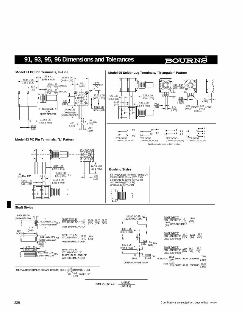
Specifications are subject to change without notice.226
SEE DETAILFOR
SHAFT OPTIONS
10.16(.40)
1 2 3
Model 91 PC Pin Terminals, In-Line
1
3
12
2
5.08(.20)
Model 93 PC Pin Terminals, "L" Pattern
3/8 THREADLESS (9.53mm) (STYLE "D")3/8-32 UNEF (9.53mm) (STYLE "A")1/4-32 UNEF (6.35mm) (STYLE "C")M10 X 0.75-6g (STYLE "R")M7 X 0.75-6g (STYLE "U")
Bushing Styles
10.16(.40)
31
2 2
13
.41(.016)
Model 95 Solder Lug Terminals, "Triangular" Pattern
SEENOTE
Shaft Styles
*DIMENSIONS ARE IN MM
SHAFT TYPE "W"STD. LENGTHS "L" 1"FINGER KNURL, FOR USEWITH BUSHING A OR D
SHAFT TYPE "R"STD. LENGTHS "L" (5/8), (3/4), (7/8)USES BUSHING R
SHAFT TYPE "T"STD. LENGTHS "L" (1/2), (5/8), (7/8)USES BUSHING U
3
1 2
4
DPST (NO/NC)(TYPES 50, 51, 56, 57)
3
1
4
2
DPST (NC/NC)(TYPES 54, 55, 60, 61)
3
1
DPST (NO/NO)(TYPES 52, 53, 58, 59)
42
3
1DPST (NC/NC)(TYPES 70, 71, 72, 73)
4
56
2
Switch contacts shown in detent position.
22.86 ± .43(.90 ± .017)
12.7(.50)
.79 ± .41(.031 ± .016)
9.53 ± .38(.375 ± .015)
(STYLE A)
6.35 ± .38(.250 ± .015)
(STYLE C)
15.88 ± .38(.625 + .015)
1.37(.054)
2.36(.093)
11.05 ± .20(.435 ± .008)
15.29 ± .56(.602 ±.022)
(MODEL 91 ONLY)
DIA.13.72(.54)
15.88 ± .38(.625 ± .015)
9.53 ± .38(.375 ± .015)
.81(.032) DIA.2.54
(.100)2.54
(.100)
5.97 ± .38(.235 ± .015)
.81(.032)
DIA. TYP.
10.16 ± .30(.40 ± .012)
5.08 ± .38(.20 ± .015) TYP.
11.05 ± .20(.435 ± .008)
12.7 ± 1.02(.50 ± .040)
4.45 ± .38(.175 ± .015)
5.59 ± .20(.220 ± .008)
4.45 ± .38(.175 ± .015)
2.54(.100) 2.54
(.100)
5.08 ± 1.02(.200 ± .040)
2.03(.080)
3 PLCS.
(.040) WIDE X (.090) LONG3 PLCS.
1.02 2.29
1.60+.38/-.00(.063+.015/-.000)
6.31+.025/-.076(.2485+.001/.003)
DIA
6.31+.025/-.076(.2485+.001/.003)
DIA.
5.49(.216)
1.19(.047)
6.31+.025/-.076(.2485+.001/.010)
DIA.
14.27 ± .25(.562 ± .010)
1.80 ± .25(0.07 ± .001)
1.00(.04)1.50 ± .25
(0.06 ± .001)
13.16+.00/-.15(.1245+.000/-.006)
DIA.
6.0(.236)
DIA.
DIA.3.988(.157)
SHAFT TYPE "B" STD. LENGTHS "L" (1/2), (5/8),
12.7 15.88 19.05(3/4),
22.23(7/8)
SHAFT TYPE "C"STD. LENGTHS "L" (3/4), (7/8)USES BUSHING A OR D
19.05 22.0
SHAFT TYPE "D"STD. LENGTHS "L" (1/2), (5/8),
(3/4) USES BUSHING C
12.7 15.88
19.05
NOTE: FOR (.750) SHAFT - FLAT LENGTH IS (.313)
FOR (.875) SHAFT - FLAT LENGTH IS (.440)
19.05 7.95
11.18
TOLERANCES EXCEPT AS SHOWN: DECIMAL .XXX ± (.015 )FRACTION ± 1/64
.XX ± (.38)
ANGLE ±5°
.128
.005
16.0 19.05 22.0
16.0 22.012.0
.79(0.03)
22.23
USES BUSHING A OR D
DIMENSIONS ARE: METRIC(INCHES)
91, 93, 95, 96 Dimensions and Tolerances
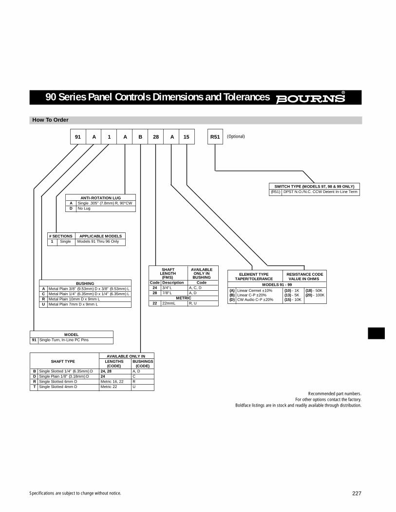
Specifications are subject to change without notice. 227
SWITCH TYPE (MODELS 97, 98 & 99 ONLY)(R51) DPST N.O./N.C. CCW Detent In-Line Term
How To Order
ANTI-ROTATION LUGA Single .305” (7.8mm) R, 90°CWD No Lug
# SECTIONS APPLICABLE MODELS1 Single Models 91 Thru 96 Only
AVAILABLE ONLY INSHAFT TYPE LENGTHS BUSHINGS
(CODE) (CODE)B Single Slotted 1/4” (6.35mm) D 24, 28 A, DD Single Plain 1/8” (3.18mm) D 24 CR Single Slotted 6mm D Metric 16, 22 RT Single Slotted 4mm D Metric 22 U
ELEMENT TYPE RESISTANCE CODETAPER/TOLERANCE VALUE IN OHMS
MODELS 91 - 99
(A) Linear Cermet ±10% (10) - 1K (18) - 50K(B) Linear C-P ±20% (13) - 5K (20) - 100K(D) CW Audio C-P ±20% (15) - 10K
SHAFT AVAILABLELENGTH ONLY IN(FMS) BUSHING
Code Description Code24 3/4”L A, C, D28 7/8”L A, D
METRIC22 22mmL R, U
BUSHINGA Metal Plain 3/8” (9.53mm) D x 3/8” (9.53mm) LC Metal Plain 1/4” (6.35mm) D x 1/4” (6.35mm) LR Metal Plain 10mm D x 9mm LU Metal Plain 7mm D x 9mm L
MODEL91 Single-Turn, In-Line PC Pins
91 A 1 A B 28 A 15 R51
90 Series Panel Controls Dimensions and Tolerances
(Optional)
Recommended part numbers.For other options contact the factory.
Boldface listings are in stock and readily available through distribution.

Specifications are subject to change without notice.228
3851/3852/3856 - 3/4” Diameter Panel Control
FOR ORDERING INFORMATION SEE PAGE 229.
Initial Electrical Characteristics1
3851 3852/3856Conductive Plastic Element Cermet Element
Standard Resistance RangeLinear Tapers (A, B, E, and H) ..................................1K to 1 megohm ......................................................100 ohms to 1 megohmAudio Tapers (C, D, F, and G) ..................................1K to 1 megohm ......................................................1K ohms to 1 megohm
Resistance Tolerance..................................................±20% ........................................................................±10%Zero Base Linearity ....................................................(B, D, & G tapers) ±20% ..........................................(A, C, & F tapers) ±10%
(E taper) ±10% (H taper) ±5%Independent Linearity ................................................±10% ........................................................................(A & H tapers) ±5%Absolute Minimum Resistance ..................................2 ohms maximum .................................................... 2 ohms maximumContinuity....................................................................Maintained for full mechanical angle ........................Maintained for full mechanical angleEffective Electrical Angle ............................................250° ±5° ....................................................................250° ±5°Contact Resistance Variation......................................±1% ..........................................................................±3% of total resistance or 3 ohms
(whichever is greater)Dielectric Withstanding Voltage..................................MIL-STD-202, Method 301 ......................................MIL-STD-202, Method 301
Sea Level ................................................................900 VAC minimum ....................................................900 VAC minimum70,000 Feet ..............................................................350 VAC minimum ....................................................350 VAC minimum
Insulation Resistance (500 VDC) ................................1,000 megohms minimum ........................................1,000 megohms minimumPower Rating (Voltage Limited By Power
Dissipation or 316 VAC, Whichever Is Less)+70°C ......................................................................(B & E tapers) 1 watt ................................................(A & H tapers) 2 watts
(D & G tapers) 0.5 watt..............................................(C & F tapers) 1 watt+125°C ....................................................................0 watt+150°C ......................................................................................................................................................0 watt
Theoretical Resolution ................................................Essentially infinite......................................................Essentially infinite
Environmental Characteristics1
Operating Temperature..................................................................................................................................-1°C to +125°CStorage Temperature Range ......................................-65°C to +125°C ......................................................-65°C to +150°CTemperature CoefficientOver Storage Temperature Range ..............................±1,000PPM/°C..........................................................±150PPM/°CVibration ....................................................................20G ..........................................................................20G
Total Resistance Shift ..............................................±2% maximum ........................................................±2% maximumVoltage Ratio Shift ..................................................±5% maximum ........................................................±6% maximum
Shock ........................................................................100G ........................................................................100GTotal Resistance Shift ..............................................±2% maximum ........................................................±2% maximumVoltage Ratio Shift ..................................................±5% maximum ........................................................±6% maximum
Load Life ....................................................................1,000 hours ..............................................................1,000 hoursTotal Resistance Shift ..............................................±10% maximum ......................................................±3% maximum
Rotational Life (No Load) ............................................100,000 cycles..........................................................50,000 cyclesTotal Resistance Shift ..............................................±15% maximum ......................................................±5% or 5 ohms (whichever is greater)
Moisture Resistance ..................................................MIL-STD-202, Method 103, Condition B..................MIL-STD-202, Method 103, Condition BTotal Resistance Shift ..............................................±10% maximum ......................................................±2% maximumInsulation Resistance (500 VDC)..............................100 megohms minimum ..........................................100 megohms minimum
Mechanical Characteristics1
Shaft Torque................................................................(A & B bushings) .05 to 6.0 oz.-in. ............................3852 (A & B bushings) 0.5 to 6.0 oz.-in.(0.35 to 4.23 Ncm) (0.35 to 4.23 Ncm)(C & E bushings) 0.3 to 6.0 oz.-in. (C & E bushings) 0.3 to 6.0 oz.-in.(0.21 to 4.23 Ncm) (0.21 to 4.23 Ncm)
3856 — 0.15 to 3.0 oz.-in.(0.11 to 2.12 Ncm)
Stop Strength..............................................................5 in.-lb. (56.5 Ncm) ..................................................5 in.-lb. (56.5 Ncm)Mechanical Angle ......................................................280° ±5° ....................................................................3852 — 280° ±5
3856 — 1350° ±50°Weight ........................................................................30 grams maximum ..................................................30 grams maximumTerminals ....................................................................Printed circuit terminals or solder lugs ....................Printed circuit terminals or solder lugsMarking ......................................................................Manufacturer’s trademark, wiring diagram, ..............Manufacturer’s trademark, wiring diagram,
date code, resistance, manufacturer’s date code, resistance, manufacturer’spart number part number
1AT ROOM AMBIENT: +25°C NOMINAL AND 50% RELATIVE HUMIDITY NOMINAL, EXCEPT AS NOTED.
Features Single-turn (3851 and 3852) Linear and audio tapers 3-3/4-turn (3856) Wide resistance range Minimal depth package Good resolution
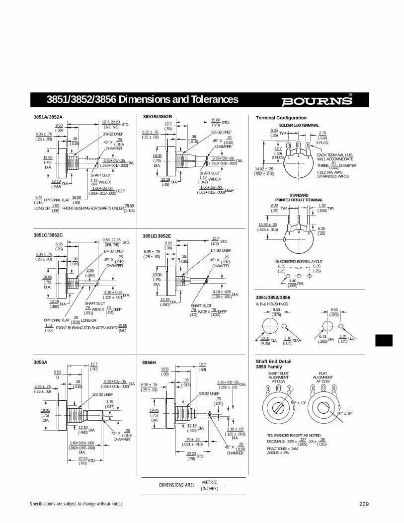
Specifications are subject to change without notice. 229
3851/3852/3856 Dimensions and Tolerances
DIMENSIONS ARE: METRIC(INCHES)
9.53(.38)
3/8-32 UNEF
3851A/3852A 3851B/3852B
19.05(.75) DIA.
3/8-32 UNEF
1/4-32 UNEF
3851C/3852C
1/4-32 UNEF
3851E/3852E
3/8-32 UNEF
3856A
3/8-32 UNEF.
3856H
6.35(.25) 2.79
(.110)3 PLCS.
14.02 ± .25(.552 ± .010)
Terminal Configuration
SOLDER LUG TERMINAL
1 32
1 32
SUGGESTED BOARD LAYOUT
STANDARDPRINTED CIRCUIT TERMINAL
3851/3852/3856A, B & H BUSHINGS
Shaft End Detail3850 Family
SHAFT SLOTALIGNMENT
AT CCW
FLATALIGNMENT
AT CCW
50° ± 10°
40° ± 10°
6.35 ± .76(.25 ± .03) .38
(.015)
19.05(.75) DIA.
12.7, 22.23 (1/2, 7/8)
45° X (.010)CHAMFER
.25
DIA.6.35+.03/-.05(.250+.001/-.002)
SHAFT SLOT1.19 WIDE X.0471.60+.38/.00
(.063+.015/-.000)
12.19(.480)
DIA.
DEEP
OPTIONAL FLAT
LONG OR FRONT BUSHING FOR SHAFTS UNDER
5.49(.216)
16.00(.63)
1.52(.06)
28.58(1-1/8)
OPTIONAL FLAT LONG OR
FRONT BUSHING FOR SHAFTS UNDER
.25(.010)
1.52(.06)
15.88(5/8)
12.7(.50)
6.35 ± .76(.25 ± .03) .38
(.015)
15.88 (5/8)
45° X (.010)CHAMFER
.25
DIA.6.35+.03/-.05(.250+.001/-.002)
DIA.12.19(.48)
DEEP
SHAFT SLOT1.19 WIDE X
(.047) 1.60+.38/-.00
(.063+.015/-.000)
TYP.
12.7(.50)
2 PLCS. EACH TERMINAL LUGWILL ACCOMMODATE
THREE .81 DIAMETER
(.812 DIA. AWGSTRANDED) WIRES.
(.032)
6.35(.25) TYP.
15.88 ± .38(.625 ± .015)
1.02(.040) TYP.
6.35(.25)
6.35(.25)
6.35(.25)
1.40(.055) DIA.
9.53(.375)
10.31(4.06) DIA.
3.18(.125) DIA.
9.53(.375)
6.73(.265) DIA.
3.18(.125)DIA.
TOLERANCES EXCEPT AS NOTED:DECIMALS: .XXX ± .127 .XX ± .38
FRACTIONS: ± 1/64ANGLE: ± 3%
(.005), (.015)
6.35 ± .76(.25 ± .03)
6.35(.25)
9.53, 22.23 (3/8, 7/8)
.38(.015)
45° X (.010)CHAMFER
.2545° X (.010)
CHAMFER
.25
3.18 ± 0.25(.125 ± .001) DIA.
SHAFT SLOT.79 WIDE X .76 DEEP
(.031) (.03)
9.53(.38)
12.7 (1/2)
.38(.015)
19.05(.75)DIA.
DIA.12.19(.480)
3.18 ± .025(.125 ± .001) DIA.
SHAFT SLOT.79 WIDE X .76 DEEP
(.03) (.031)
6.35 ± .76(.25 ± .03)
.38(.015)
9.53()
12.7(.50)
DIA.6.35+.03/-.05(.250+.001/-.002)
1.19(.047)
45° X (.010)CHAMFER
.2512.19(.480) DIA.
1.60+3.81/-.000(.063+.015/-.000)
DIA.22.23(7/8)
STD.
45° X (.010)CHAMFER
.25
22.23(7/8)
STD.
12.19(.480) DIA.
19.05(.75) DIA.
19.05(.75) DIA.
6.35 ± .76(.25 ± .03)
12.7(.50)9.53
(.38).38
(.015) DIA.6.35+.03/-.05(.250 ± .03)
.79(.031)
3.18 ± .03(.125 ± .003)
DIA.
STD.STD.
6.35 ± .76(.25 ± .03)
19.05(.75)DIA.
DIA.12.19(.480)
STD. STD.
.79 ± .25(.031 ± .010)
2.36(.094)
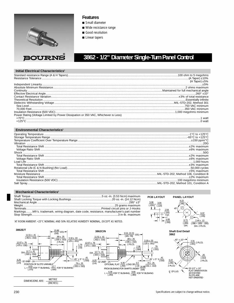
Specifications are subject to change without notice.230
Initial Electrical Characteristics1
Standard resistance Range (A & H Tapers)..........................................................................................................................................100 ohm to 5 megohmsResistance Tolerance ........................................................................................................................................................................................(A Taper) ±10%
(H Taper) ±5%Independent Linearity.........................................................................................................................................................................................................±5%Absolute Minimum Resistance......................................................................................................................................................................2 ohms maximumContinuity .........................................................................................................................................................................Maintained for full mechanical angleEffective Electrical Angle............................................................................................................................................................................................260° ±10°Contact Resistance Variation................................................................................................................................................................±3% of total resistanceTheoretical Resolution ...................................................................................................................................................................................Essentially infiniteDielectric Withstanding Voltage ......................................................................................................................................................MIL-STD-202, Method 301
Sea Level ...................................................................................................................................................................................................750 VAC minimum70,000 Feet................................................................................................................................................................................................350 VAC minimum
Insulation Resistance (500 VDC) ......................................................................................................................................................1,000 megohms minimumPower Rating (Voltage Limited by Power Dissipation or 350 VAC, Whichever is Less)
+70°C ............................................................................................................................................................................................................................1 watt+125°C ..........................................................................................................................................................................................................................0 watt
Environmental Characteristics1
Operating Temperature .....................................................................................................................................................................................-1°C to +125°CStorage Temperature Range ...........................................................................................................................................................................-65°C to +125°CTemperature Coefficient Over Temperature Range ..............................................................................................................................................±150 ppm/°CVibration .............................................................................................................................................................................................................................20G
Total Resistance Shift .....................................................................................................................................................................................±2% maximumVoltage Ratio Shift ..........................................................................................................................................................................................±6% maximum
Shock ..................................................................................................................................................................................................................................50GTotal Resistance Shift .....................................................................................................................................................................................±2% maximumVoltage Ratio Shift ..........................................................................................................................................................................................±6% maximum
Load Life .................................................................................................................................................................................................................1,000 hoursTotal Resistance Shift .....................................................................................................................................................................................±3% maximum
Rotational Life (C & N Bushing) (No Load)...........................................................................................................................................................50,000 cyclesTotal Resistance Shift .....................................................................................................................................................................................±5% maximum
Moisture Resistance ..................................................................................................................................................MIL-STD-202, Method 106, Condition BTotal Resistance Shift .....................................................................................................................................................................................±2% maximumInsulation Resistance (500 VDC) ......................................................................................................................................................100 megohms minimum
Salt Spray...................................................................................................................................................................MIL-STD-202, Method 101, Condition A
Mechanical Characteristics1
Shaft Torque .........................................................................................5 oz.-in. (3.53 Ncm) maximumShaft Locking Torque with Locking Bushings ...................................................20 oz.-in. (14.12 Ncm)Mechanical Angle ...................................................................................................................295° ±3°Weight ...................................................................................................................25 grams maximumTerminals..............................................................................................Printed circuit pins or J-HooksMarkings........Mfr’s. trademark, wiring diagram, date code, resistance, manufacturer’s part numberStop Strength............................................................................................................3 in-lb. maximum
DIA.
45°
DIA. 2 PLCS.
Shaft End Detail3862
45° ± 15°
C OF LUGL
32-1/2° ± 10°FLAT ORIENTATION@ CCW ENDSLOTS ARENOT ORIENTED
3862C/N
L
OPTIONAL FLAT LONG OR
FROM BUSHING FOR SHAFTS UNDER
3862E/TSTD.
2 PLCS.L
DIA.
45° ± 5° X
POSITION OF SLOTS VARIABLE-32 UNEF - 2A
L =
DIA.
FOR "T" BUSHING,
DIA.
6.22(.245)
6.22(.245)
2.44 ± .13(.096 + .005/ - .000)
6.73(.265)
2 PLCS.2.31
(.091)
2 PLCS.
.25(.010)
2 PLCS.
6.22(.245)
12.07 ± .76(.475 ± .030)
11.51 ± .41(.453 ± .016)
12.7 ± .41(.500 ± .016)
6.25(1/4)
12.7(.500)
9.53(.375)
FOR "E" BUSHING
15.88(5/8)
.89 ± .25(.035 ± .010)
.79 ± .25(.031 ± .010)
1.79(.03)
.41(.016)
3.18 ± .03(.125 ± .001)
12.07 ± .76(.475 ± .030)
11.51 ± .41(.453 ± .016)
12.7 ± .41(.500 ± .016)
-32 UNEF - 2A6.25(1/4)
L = FOR "C" BUSHING, 9.65(.380)
6.35(.250)
FOR "N" BUSHING
45° ± 5° X.41
(.016).79 ± .25
(.031 ± .010)
.79(.031)
DIA.3.18 ± .03
(.125 ± .001)
STD.9.53, 22.23(3/8, 7/8)
2 PLCS.
.89 ± .25(.035 ± .010)
2.38(.094)
6.35(.250)
3.3(.13) 16.88
(5/8)
TYP.
2.54(.100)
5.08(.200)
3.04(.120)
5.08(.200)
PANEL LAYOUTPCB LAYOUT
3862 - 1/2” Diameter Single-Turn Panel Control
Features Small diameter Wide resistance range Good resolution Linear tapers
DIMENSIONS ARE: METRIC(INCHES)
1AT ROOM AMBIENT: +25°C NOMINAL AND 50% RELATIVE HUMIDITY NOMINAL, EXCEPT AS NOTED.

Specifications are subject to change without notice. 231
SHAFT TYPE AVAILABLE ONLY IN(FMS) & DIAMETER MODELS BUSHINGS
12 3/8” (9.53mm) L X 1/8” (3.18mm) D 3851, 3852, 3862 C
16 1/2” (12.7mm) L X 1/8” (3.18mm) D3851, 3852 C, E3862 C
20 5/8” (15.88mm) L X 1/4” (6.35mm) D 3851, 3852 A, B
28 7/8” (22.20mm) L X 1/4” (6.35mm) D3851, 3852 A, B3856 A
BUSHING APPLICABLE MODELSA Plain 3/8” (9.53mm) D x 3/8” (9.53mm) L 3851, 3852, 3856C Plain 1/4” (6.35mm) D x 1/4” (6.35mm) L 3851, 3852, 3862
3852 A 28 2 103 A
Consult factory for lengths not shown.
MODEL3852 3/4” (19.05mm) D Single-Turn Cermet3862 1/2” (12.7mm) D Single-Turn Cermet
TERMINAL STYLE ANDSHAFT TYPE
2 Solder Lugs*, Slotted End6 PC Pins, Slotted End
*Model 3862 comes with J-hook solder lugs.
ELEMENTAPPLICABLE MODELSTAPER/TOLERANCE
A Linear ±10% 3852, 3856, 3862
*The maximum resistance range for audio tapers is1000 ohms to 2.5 megohms.
RESISTANCECODE/VALUE
(IN OHMS)Models 3851,
3852,3856, 3862
(102) 1K(502) 5K(103) 10K(503) 50K(104) 100K
PC PIN TERMINAL
12.06 ± .762(.475 ± .03)
.723(.0285)
5.08(0.20)
2.54(0.10)
3.04(.12)
5.08(.20)
2
13
J-HOOK TERMINAL
6.53(.250)MAX.
2.286(.09)TYP.
5.08(0.20)
2.54(0.10)
4.953(.195)
8.89(.35)
2
13
REF ONLY
.762(.03)TYP.
How To Order
DIMENSIONS ARE: METRIC(INCHES)
3800 Series Dimensions and Tolerances
Dimensional Drawings And Tolerances

Specifications are subject to change without notice.232
Open-Frame Slide Potentiometer
Electrical Characteristics
20MM
Standard Resistance Range...........Linear.......... 2K 5K 10K 20K 50K 100K 200K 500K
(ohms) Audio .......... 5K 10K 20K 50K 100K 200K 500K
Resistance Tolerance ......................................... ±20%, All Resistance/Tapers
Resistance Taper ............................Linear ....... B Tapers (see taper curves)
Independent Linearity......................................... ±5% for B Tapers
Absolute Minimum Resistance........................... 1% or 100 ohms, whichever is less, for B taper
Continuity ........................................................... Maintained for full stroke
Effective Electrical Travel.................................... 90% of Mechanical Travel
Peak Noise (CRV) Linear/Audio.......................... 2% / 5%
Theoretical Resolution........................................ Essentially Infinite
Dielectric Strength (Sea Level) ........................... 500 VAC, 1 minute, between Lever and Terminals
Insulation Resistance (500 VDC) ........................ 1,000 megohms minimum between Lever and Terminals
Power Rating at 70°C .....................Linear ......... 0.1 Watt
(0 Watt at 90°C) Audio .......... 0.05 Watt
Maximum Working Voltage................................. Power Dissipation or 350 VAC, whichever is less
Tracking Error (Dual Only)................................... 4 dB maximum; 0 to -40 dB
Environmental Characteristics
Storage Temperature.......................................... -20°C to +90°C
Temperature Coefficient of Resistance .............. ±1,000ppm/°C
Vibration (10 to 55 Hz, 1.5mm)........................... Voltage Ratio Change: ±5% maximum. Total Resistance Shift: ±2% maximum
Load Life ............................................................ (Pre-conditioning: 55°C, 20% RH, 24 ± 4 Hours)
(Rated Power at 25°C for 1,000 Hours).............. Total Resistance Shift: ±10%
Sliding Life ......................................................... Total Resistance Shift: ±5% = Linear; 2K, 5K, 10k, 20K, 50K,
(No Load - 15,000 Cycles) ±10% = Linear; 100K, 200K, 500K, & Audio; 2K to 500k
Moisture Resistance (96 Hours @ 40°C ............ Total Resistance Shift: Linear ±12% maximum, Audio ±20% maximum
90-95% RH, Rated Power) Insulation Resistance: 100 megohms minimum
Soldering Heat (3 Seconds @ 350°C)................. Total Resistance Shift: ±5% maximum
Mechanical Characteristics
Operating Force ................................................. 15 to 150 Gr
Stop Strength ..................................................... 1.5 Kg minimum
Stroke ................................................................. 20mm
Terminals ............................................................ PC Pins (Vertical or Horizontal)
Markings............................................................. Trademark, date code, taper, and resistance (ex. B10K) and Japan
Features Minimal installation space for maximum
design flexibility Linear or audio taper versions Wide assortment of options

Specifications are subject to change without notice. 233
5.3(.209)
1 3
2
B
C
P.C.B. MOUNTING HOLE DETAIL
12
3
CL
LA
12.5(.492)
1.8(.071) B
1.3(.051)
2 PLCS.C
Single ElementVertical Mount
DIMENSIONS ± 0.20 (± 0.5)MODEL
L (STROKE) A B CSSVA30XXXXXXSSVA20XXXXXXSSVA15XXXXXXSSVA10XXXXXX
1.81 (30).787 (20).591 (15).394 (10)
1.969 (50)1.575 (40)1.378 (35)1.181 (30)
1.535 (39)1.142 (29).945 (24).748 (19)
1.953 (49.6)1.559 (39.6)1.362 (34.6)1.165 (29.6)
0 10 20 30 40 50 60 70 80 09 100
10
20
30
40
50
60
70
80
90
100
(%)
TERM. 1 TERM. 3MECHANICAL TRAVEL
TERM
. 1–2
OUT
PUT
VOLT
AGE
TERM
. 1–3
IN
PUT
VOLT
AGE
X 10
0%
(%) B TAPER - Linear (Straight)
TAPER CURVES
1.5(.059)
12.0(.472) REF.
5.0 ± 0.1(.197 ± .004)
0.25 ± .275(.010 .011)
4.0(.157)
15.2(.598)REF.
4.55(.179)
REF.3.3 (.130)
5.25(.207) 0.8 ± 0.1
(.031 ± .004)2 PLCS.
0.4 ± 0.1(.016 ± .004)
2 PLCS.
0.2 (.008)
PLCS.
2.75(.108)
1.0 ± 0.1(.039 ± .004)
2 PLCS.
0.4 ± 0.1(.016 ± .004)
2 PLCS.
16.5(.650) REF.
2.0 (.079)
REF.
6.5(.256) REF.
2.0(.079)
1.0(.039)
1.2 + 0.1/ – 0(.047 ± .004/-.000)
DIA. 4 PLCS.
2.75(.108)
L4.0
(.157)
A
B
Single ElementHorizontal Mount
DIMENSIONS ± 0.20 (± 0.5)MODEL
L (STROKE) A BSSHA30XXXXXXSSHA20XXXXXXSSHA15XXXXXXSSHA10XXXXXX
1.81 (30).787 (20).591 (15).394 (10)
1.535 (39)1.142 (29).945 (24).748 (19)
1.929 (49)1.535 (39)1.339 (34)1.142 (29)
0.4 ± 0.1(.016 ± .004)
4 PLCS.
CL
1.75(.069)
1 3
2
P.C.B. MOUNTING HOLE DETAILA
3 1
2
1.5(.059)1.0
(.039)
12.0(.472) REF.
5.0 ± 0.1(.197 ± .004)
3.05(.120)
2.5(.098) 4 PLCS.
1.0(.039)
4 PLCS.6.15(.242) REF.
15.2(.598)REF.
11.2(.441) REF.
4.55(.179)
5.0(.197) 8.3 ± 0.5
(.327 ± .020)
1.7(.067)
1.0(.039)
2.0(.079)
1.2 + 0.2/ – 0(.047 + .008/-.000)
DIA. 4 PLCS. 8.3(.327)
DIMENSIONS ARE: METRIC(INCHES)
Slide Potentiometer - Dimensions and Tolerances
Non-stock adjustable

Specifications are subject to change without notice.234
TERMINAL STYLECode
HV
DescriptionPC Pin, HorizontalPC Pin, Vertical
SECTIONSCode
SDescriptionSingle Element
PRODUCT CLASSCode
SDescriptionSlide Potentiometer
ELEMENT TYPE/TAPERCode
BDescriptionLinear ± 20%
RESISTANCE CODECode102202502103203503104204504
Resistance 1,000* 2,000 5,000 10,000 20,000 50,000100,000200,000500,000**
* Available only on linear taper 10mm and 15mm stroke versions.**Available only on 20mm stroke versions.
COMBINATIONSCode
0001
DescriptionNo DetentCenter Detent
STROKE LENGTHCode
20Description 20 Slide Stroke(.787)
LEVER AND COLORCode
ADescriptionBlack 4 H x 5 W (.157) x (.197)
S S V A 2 0 B 1 0 3 0 0
Slide Potentiometers - How to Order

Specifications are subject to change without notice. 235
Slimline Potentiometer
FOR ORDERING INFORMATION SEE PAGE 237.
Electrical Characteristics - PotentiometerStandard Resistance Range
Linear Tapers................................................................................................................................................................................500 ohms to 1.5 megohmsAudio Tapers......................................................................................................................................................................................1K ohms to 500K ohms
Resistance Tolerance (All Tapers) .....................................................................................................................................................................................±20%Independent Linearity....................................................................................................................................................................................±5% (linear taper)Absolute Minimum Resistance......................................................................................................................................................................5 ohms maximumEffective Electrical Angle.............................................................................................................................................................................................270° ± 5°Dielectric Withstanding Voltage ......................................................................................................................................................MIL-STD-202, Method 301
Sea Level ................................................................................................................................................................................................1,000 VAC minimum70,000 Feet................................................................................................................................................................................................500 VAC minimum
Insulation Resistance (500 VDC) ......................................................................................................................................................................1,000 megohmsPower Rating @ 70ºC (Voltage Limited by Power Dissipation or 350 VAC, Whichever is Less)
Linear........................................................................................................................................................................................................................ .75 wattAudio ........................................................................................................................................................................................................................ .25 watt
Environmental CharacteristicsOperating Temperature .....................................................................................................................................................................+1°C to +125°CStorage Temperature ......................................................................................................................................................................................-40°C to +125°CLoad Life (1,000 Hours @ Rated Power, 20% RH, 70ºC) .......................................................................................................±10% maximum resistance shiftRotational Life ......................................................................................................................................................................................................50,000 cycles
Total Resistance ShiftLinear .......................................................................................................................................................................±10 ohms or 12%, whichever is greaterAudio.............................................................................................................................................................................................................±20% maximum
Mechanical CharacteristicsStop Strength (1/4” and 6mm Shaft Diameters)........................................................................................................................................7 in.-lb. (79.09 Ncm)Mechanical Angle........................................................................................................................................................................................................300° ± 5°Terminals ....................................................................................................................................................................................................PC pin or solder lugRunning Torque ......................................................................................................................................... 0.25 to 1.5 in.-oz. (0.18 to 1.06 Ncm) (undetented)Mounting Torque .....................................................................................................................................................................7 in.-lbs. (79.09 Ncm) maximumDetents ................................................................................................................................................................................................Center, 10, 20, 30, noneShaft Variations......................................................................................................................................................................................................See diagram
"F"
"L"
M9 X 0.75-6g SPL
DIA.
1 2 3
"E" 2 PLCS.
3 PLCS.
PC PINS (Rear Facing)
"F" =
"L" = SEE SHAFT LENGTH TABLE
"E" = 3 PLCS.
"F"
1 3
2 TOLERANCES WHERE NOT SHOWN.XX = ± .010.XXX = ± .005
DIA.
OR OR
7.42(.292)
9.0(.354)
1.52(.060)6.25
(.246) 6.35(.250)
9.53(.375)
14.7 ± 0.5(.578 ± .020)
22.2 ± 0.25(.874 ± .010)
.320(8.13)
11.1(.437)
11.1(.437)
0.79(.031)
2.54(.100)
5.08(.200)
.28(.011) 6.25
(.246)
8.36(.329)
PANEL HOLE DIMENSIONS9.53
(.375)
9.14(.360) DIA.
3.18(.125) DIA.
*For lower contact resistance, consult factory.For additional features or specifications not shown, consult factory.
Features Space saving design Wide range of resistance values PC pin or solder lug terminals Metric shaft and bushing option Mounting brackets available Linear or audio taper versions
Product Dimensions
DIMENSIONS ARE: METRIC(INCHES)

Specifications are subject to change without notice.236
2 PLCS.3 PLCS.
3 PLCS.
"L"
"F"
3 PLCS.
"F" =
SOLDER LUGS(Dimensions not given are the same asPC pins (rear facing).
OR
4 PLCS.
"L"
2 PLCS."E" 2 PLCS.
DIA. 7 PLCS.
PC PINS (Rear Facing)With Rear Mounting Bracket
"L"
4 PLCS. 3 PLCS."E" 2 PLCS.
DIA. 7 PLCS.
2 PLCS.
"E" 2 PLCS.
2 PLCS.
PC PINS (Side Exit)With Side Mounting Bracket
"D"
120° ± 2°
DIA.
60° ± 2° 60° ± 2°
SHAFT STYLES AND ORIENTATION (Full CCW Rotation)
Shaft Style C
"D"
DIA.
Shaft Style J Shaft Style R Shaft Style B Shaft Style Y
DIA.
"D" dimensions extend from shaft end to bushing face "D" = (shaft length, FMS) – (bushing length)
Slot depth (Y shaft) 9.65 (.380)for shafts <1" (2.54) length 14.7 (.520) for shafts ≥1"(2.54) length
Shaft Orientations
Shaft Styles C, J Shaft Styles B, R Shaft Style Y
TOLERANCES WHERE NOT SHOWN .XX = ± .010.XXX = ± .005
8.36(.329)
6.25(.246)
.28(.011)
7.75(.305) 5.08
(.200)2.03
(.080)
1.02 X 2.29(.040 X .090)
22.2 ± 0.25(.874 ± .010)
6.35(.250)
9.53(.375)
0.76(.030)
6.83(.269)
5.87(.231)
8.31(.327)
23.37(.92)
17.07(.672)
18.87(.743)
15.2(.600)
11.43(.450)
1.19(.047)
"E" = OR2.54(.100)
5.08(.200)
"E" = OR2.54(.100)
5.08(.200)
0.76(.030)
17.07(.672)
0.79(.031)
6.83(.269)
12.62(.497)
23.37(.92)
5.48(.216)
5.08(.200)
1.19(.047)
11.43(.450)
7.62(.300)
5.54 ± .076(.218 ± .003)
6.32 + 0.03/ - 0.08(.249 + .001/ - .003)
3.94 + .051/ - .025(.155 + .002/ - .001)
DIA.4.75 ± .051
(.187 ± .002) 1.6(.063)
1.19(.047)
6.00(.236)
1.6(.063)
1.19(.047)
DIA.
6.32 + 0.03/ - 0.08(.249 + .001/ - .003)
1.57(.062)
4.7(.185)
Slimline Potentiometers - Dimensions and Tolerances

Specifications are subject to change without notice. 237
SHAFT LENGTH (FMS)Available Shaft
Code Description Styles24 3/4” (19mm) Length B, C, J, Y28 7/8” (22.2mm) Length B, C, J, Y
Metric24 24mm Length R
P C W 1 J - B 2 4 - B A B 1 0 3
SHAFT STYLES (See Outline Drawing)Code Description
B 1/4” (6.35mm) Dia. SlottedC 1/4” (6.35mm) Dia. Flat HeadR 6mm Dia. Slotted (Use Metric
Lengths Only)
ANTI-ROTATION LUGCode Description
J 9:00 Position
NO. SECTIONS1 Single
BUSHING CONFIGURATIONAvailable Shaft
Code Description StylesW 9mm x .250” (6.35mm) Length All
Threaded M9 x 0.75 6g 5 Pl
RESISTANCE VALUESCode TR Code TR502 5KΩ 103 10KΩ
503 50KΩ104 100KΩ
ELEMENT TAPER VERSIONSCode Taper Description
B Lin. CP± 20%
DETENT CONFIGURATIONSCode Taper Description
A No Detents
HOUSING TERMINAL CONFIGURATIONCode
Features B KRear Mounting Bracket X XSide Mounting BracketRear Facing Terminals .100” (2.54mm) Centers X XSide Exiting Terminals .100” (2.54mm) CentersSide Exiting Terminals .200” (5.08mm) CentersSolder Lugs .200” (5.08mm) CentersRear Facing Terminals .200” (5.08mm) CentersHardware Included X
Panel mount hardware not included as standard on bracketed versions.The sample part number demonstrates the identification code for Bourns Slimline Potentiometers.The part number shown is a commonly used model, typically available from stock.
Slimline Potentiometers - How To Order

PDA17 Series - 17mm Rotary Potentiometer
Specifications are subject to change without notice.238
B
PDA17-SS
5
L
TEETH KNURLM7x0.75
50°
R 60°
3 PLCS.
R
HOLES2 PLCS.
SHAFT SHOWN IN CCW POSITION
6.0(.24)
DIA.6.0
(.24)
1.0(.039)
1.5(.059)
DIA.17.0(.67)
7.0(.275)10.5
(.413)
21.0(.827)
12.5(.492)
13.5(.531)
9.4(.370)
DIA.
2.0(.078)
DIA.
7.5(.295)0.4
(.015)
2.8(.110)
1.5(.059)
DIA.1 2 3
B
PDA17-SN
5
L
TEETH KNURLM7x0.75
50°
60°
SHAFT SHOWN IN CCW POSITION
6.0(.24)
DIA.6.0
(.24)
DIA.17.0(.67)
7.0(.275)
1.5(.059)
1.0(.039)
R 12.5
(.492)
9.4(.370)
DIA.
7.5(.295)0.4
(.015)
2.8(.110)
1 2 3 3 PLCS.
1.5(.059)
DIA.
Features Carbon element Switch option Wide assortment of resistance tapers
Applications Audio/TV sets Car radio Amplifiers/mixers/drum machines/
synthesizers PCs/monitors Appliances
Product Dimensions
L20 25
(.787) (.984)
B9 12
(.354) (.472)
PDA17 Series DimensionsK-Shaft (18 Toothed Serration Type)
1
2
3SCHEMATIC
Electrical CharacteristicsTaper .................................................A, BStandard Resistance Range
............................1K ohms to 1M ohmsStandard Nominal Resistance Value
..............See standard resistance tableStandard Resistance Tolerance .....±20%Residual Resistance ......Max. 1% overall
resistance
Environmental CharacteristicsPower Rating
Taper B.....................................0.1 wattTaper A ...................................0.05 watt
Maximum Operating VoltageTaper B.........................................200 VTaper A.........................................150 V
Sliding Noise..................47mV maximum
Physical CharacteristicsMechanical Angle ....................260° ±10°Rotational Torque..............50 to 350 gcmStop- End Strength ......5 kgcm minimumSwitch Torque................150 to 450 gfcmSwitch Action Angle ..................60° max.Rotational Life ....15,000 cycles minimumSoldering Condition ..............260°C max.
within 3 seconds
DIMENSIONS ARE: METRIC(INCHES)

Specifications are subject to change without notice. 239
How To Order
PDA17 - V N 20 - 102 A KModel
Terminal Configuration• S = Solder Lugs• A = PC Pins vertical/
Down Facing • V = PC Pins horizontal/
Rear Facing
Switch Option• S = Switch• N = No Switch
Standard Shaft Length• 20 = 20mm• 25 = 25mm
Resistance Code (See Table)
Resistance Taper• A = Audio Taper • B = Linear Taper
Shaft Style• K = Metal Knurled Shaft
18 Toothed Serration Type
Other configurations or styles available.
B
PDA17-AN
5
L
TEETH KNURLM7x0.75
50°
SHAFT SHOWN IN CCW POSITION
6.0(.24)
DIA.6.0
(.24)
1.0(.039)
1.5(.059)
1.5(.059)
0.4(.015)
DIA.17.0(.67)
11.0(.43)
0.4(.015)
1.2(.047) 2.5
(.098)10.0(.393)
12
3
9.4(.370)
DIA.
7.5(.295)0.4
(.015)
2.8(.110)
60°
B
PDA17-VNL
TEETH KNURLM7x0.75
50°
R
60°
RECOMMENDED PCB LAYOUT
5
SHAFT SHOWN IN CCW POSITION
DIA.17.0(.67)
1.5(.059)
4.3(.169)
7.0(.275)4.8
(.188)6.0
(.24)DIA.
6.0(.24)
1.0(.039)
8.0(.314)
2.4(.094)1.2
(.047)
9.4(.370)
DIA.
7.5(.295)0.4
(.015)
2.8(.110)
8.0(.314)
3 PLCS.
1.5(.059)
DIA.
12
3
PDA17 Series - 17mm Rotary Potentiometer
Product Dimensions
Standard Resistance Table
Resistance Resistance(Ohms) Code
1,000 1022,000 2025,000 502
10,000 10320,000 20350,000 503
100,000 104200,000 204500,000 504
1,000,000 105
1
2
3SCHEMATIC

PDB12 Series - 12mm Rotary Potentiometer
Specifications are subject to change without notice.240
Electrical CharacteristicsTaper ................................................A, BStandard Resistance Range
............................1K ohms to 1M ohmsStandard Nominal Resistance Value
..............See standard resistance tableStandard Resistance Tolerance ....±20%Residual Resistance..........Max. 10 ohms
Environmental CharacteristicsPower Rating
Taper B ..................................0.08 wattTaper A ..................................0.04 watt
Maximum Operating VoltageTaper B ........................................150 VTaper A ........................................100 V
Sliding Noise ..................47mV maximum
Physical CharacteristicsMechanical Angle ......................300° ±5°Rotational Torque..............20 to 200 gcmStop- End Strength ......3 kgcm minimumRotational Life ....15,000 cycles minimumSoldering Condition ..............260°C max.
within 3 seconds
PDB12-H
L
A
30°
RECOMMENDED PCB LAYOUT
SHAFT SHOWN IN CCW POSITION
6.0(.24)
DIA.6.0
(.24)
9.0(.354)
12.4(.488)
DIA.
2.6(.102)
8.7(.342)
3.2(.125) 4.6
(.181)
4.5(.177)
1.5(.059)
1.5(.059)
12.4(.488)
7.5(.295)
12.6(.496)
2.5(.098)
2.7(.106)
10.0(.393)
7.5(.295)
3 PLCS.
1.0(.039)
DIA.
1
23
PDB12-G
L
3.7 A
30°
RECOMMENDED PCB LAYOUT
SHAFT SHOWN IN CCW POSITION
6.0(.24)
DIA.6.0
(.24)
12.4(.488)
DIA.
4.5(.177)
1.5(.059)
1.5(.059)
4.5(.177)
10.0(.393)
3.0(.118) 4.0
(.157)
2.6(.102)
6.0(.236)
4.5(.177)
1
2
37.5
(.295)
14.0(.551)
7.5(.295)
4.0(.157) 3 PLCS.
1.0(.039)
DIA.
2.7(.106)
2.0(.078)12.0
(.472)
L20 25
(.787) (.984)
A7 12
(.275) (.472)
PDB12-H Dimensions
PDB12-G Dimensions
Features Single gang panel control Carbon element Center detent option Wide range of resistance tapers Insulated shaft styles Assortment of pin layouts
Applications Audio/TV sets Car radio Amplifiers/mixers/drum machines/
synthesizers PCs/monitors Appliances
Product Dimensions
L20 25
(.787) (.984)
A7 12
(.275) (.472)
1
2
3SCHEMATIC
DIMENSIONS ARE: METRIC(INCHES)

Specifications are subject to change without notice. 241
How To Order
PDB12 - H 4 20 1 - 103 A FModel
Terminal Config.(See individual drawings)
Option• 2 = Center Detent• 4 = No Detent
Standard Shaft Length• 20 = 20mm• 25 = 25mm
Number of Gangs• 1 = Single Gang
Resistance Code (See Table)
Resistance Taper• A = Audio Taper• B = Linear Taper
Shaft Style• F = Flat Type Insulated Shaft
Other styles available.
Standard Resistance Table
Resistance Resistance(Ohms) Code
1,000 1022,000 2025,000 502
10,000 10320,000 20350,000 503
100,000 104200,000 204500,000 504
1,000,000 105
PDB12-F L
A
RECOMMENDED PCB LAYOUT
30°
SHAFT SHOWN IN CCW POSITION
6.0(.24)
DIA.6.0
(.24)
4.5(.177)
1.5(.059)
1.5(.059)
10.0(.393)
12.8(.503)
1 2 3
3.5(.137)
3.0(.118)
3.5(.137) 3.0
(.118)
2.0(.078)
4.5(.177)
4.5(.177)
6.5(.255)
3 PLCS.
1.0(.039)
DIA.
3.0(.118)
2.1(.082)
14.4(.566)
1.6(.062)
7.5(.177)
PDB12-M
L
A
RECOMMENDED PCB LAYOUT
30°
SHAFT SHOWN IN CCW POSITION
6.0(.24)
DIA.6.0
(.24)
2.6(.102)
4.5(.177)
1.5(.059)
1.5(.059)
9.0(.354)
10.0(.393)
12.8(.503)
12.6(.496) 2.7
(.106)
10.0(.393)
7.5(.295)
1 2 3
1.6(.062)
3 PLCS.
1.0(.039)
DIA.
3.6(.141)
L20 25
(.787) (.984)
A7 12
(.275) (.472)
PDB12-M Dimensions
PDB12-F Dimensions
Product Dimensions
L20 25
(.787) (.984)
A7 12
(.275) (.472)
1
2
3SCHEMATIC
PDB12 Series - 12mm Rotary Potentiometer

PDB18 Series - 18mm Rotary Potentiometer
Specifications are subject to change without notice.242
PDB182-K
B
L
A
C
18 TEETHKNURL
M7 x P0.75
30°
SHAFT SHOWN IN CCW POSITION
6.5
6.0(.24)
DIA.6.0
(.24)
1.0(.039)
0.5(.019)
3.8(.149)
11.5(.452)
2.5(.098)
DIA.17.0(.67)
1.0(.039)
0.4(.015)
1
2 3
2.8(.110)
1.2(.047)
8.4(.330)
12.5(.492)
5.0(.204)
5.0(.204)
5.0(.204)
Electrical CharacteristicsTaper ................................................A, BStandard Resistance Range
............................1K ohms to 1M ohmsStandard Resistance Tolerance ....±20%Standard Nominal Resistance Value
..............See standard resistance tableResidual Resistance ..........Maximum 1%
Environmental CharacteristicsPower Rating
Taper B ....................................0.2 wattDual Section ..............0.125 wat
Taper A ....................................0.1 wattDual Section ..............0.06 watt
Maximum Operating VoltageTaper B ........................................200 VTaper A ........................................150 V
Sliding Noise ..................47mV maximum
Physical CharacteristicsMechanical Angle ......................300° ±5°Rotational Torque..............50 to 350 gcmClick Torque....................150 to 500 gcmStop- End Strength ......5 kgcm minimumRotational Life ....15,000 cycles minimumSoldering Condition ..............260°C max.
within 3 seconds
Standard Resistance Table
Resistance Resistance(Ohms) Code
1,000 1022,000 2025,000 502
10,000 10320,000 20350,000 503
100,000 104200,000 204500,000 504
1,000,000 105
PDB181-K
B
L
A
C
18 TEETHKNURL
M7 x P0.75
30°
SHAFT SHOWN IN CCW POSITION
6.5
6.0(.24)
DIA.6.0
(.24)
1.0(.039)
DIA.16.5
(.649)
0.5(.019) 3.6
(.141)
9.5(.374)
2.5(.098)
DIA.17.0(.67)
1.0(.039)
0.4(.015)
1
2 3
2.8(.110)
1.2(.047)
8.4(.330)
12.5(.492)
5.0(.204)
5.0(.204)
Product Dimensions
Features Single and dual section control Metal shaft styles Carbon element Center detent option Wide range of resistance tapers
Applications Audio/TV sets Car radio Amplifiers/mixers/drum machines/
synthesizers PCs/monitors Appliances
L20 25
(.787) (.984)
A12 14
(.472) (.551)
B10 12
(.393) (.472)
C2 2
(.078) (.078)
PDB18 Dimensions
How To Order
PDB18 1 - K 4 25 K - 103 A Model
Number or Sections• 1 = Single Section• 2 = Dual Section
Terminal Configuration(Pin Layout)
• K = PC Pins vertical/Down Facing
Option• 4 = No Center Detent• 2 = Center Detent
Standard Shaft Length• 20 = 20mm• 25 = 25mm
Shaft Style• K = Metal Knurled Type Shaft
18 Toothed Serration Type
Resistance Code (See Table)
Resistance Taper• A = Audio Taper • B = Linear Taper
Other styles available.
1
2
3SCHEMATIC
DIMENSIONS ARE: METRIC(INCHES)

PTV09 Series - 9mm Potentiometer
Specifications are subject to change without notice. 243
Electrical CharacteristicsTaper ................................................A, BStandard Resistance Range
............................1K ohms to 1M ohmsStandard Resistance Tolerance ....±20%Standard Nominal Resistance Value
..............See standard resistance tableResidual Resistance
................500 ohms maximum or ±1%
Environmental CharacteristicsPower Rating ............................0.05 wattMaximum Operating Voltage
....................................20 VDC, 50 VACSliding Noise ................100mV maximum
Physical CharacteristicsMechanical Angle ......................280° ±5°Rotational Torque..............10 to 100 gcmClick Torque......................40 to 200 gcmStop- End Strength ......3 kgcm minimumRotational Life ....10,000 cycles minimumSoldering Condition ..............300°C max.
within 3 seconds
2 PLCS.
RECOMMENDED PCB LAYOUT
PTV09A-2
F
40°
3 PLCS.
3 PLCS.
SHAFT SHOWN IN CCW POSITION
10.0(.393) 6.0
+0-0.1
(.236 )+0-0.0003
4.5(.177 )+0
-0.0003
+0-0.1
3.5(.137)
3.8(.149)
2.0(.078)3.3
(.129)
2.6(.102)
0.8(.031)
6.8(.267)
9.8(.385)
5.5(.216)
0.8(.031)
5.0(.196)
7.4(.291)
1.8+0.2-0.0
(.070 )+0.0007-0.0
2 PLCS.2.1+0.2-0.0
(.082 )+0.0007-0.0
8.2(.322)
5.0(.196)
1.0+0.2-0.0
(.039 )+0.0007-0.0
3.3(.129)
L ± 0.5(.019)
L20 25
(.787) (.984)
F7 12
(.275) (.472)
PTV09 Dimensions
C0.5
RECOMMENDED PCB LAYOUT
PTV09A-4
F
L ±
40°
6.0+0
-0.1
(.236 )+0-0.0003
4.5(.177 )+0
-0.0003
+0-0.1
0.8(.031)
6.8(.267)
3.5(.137)
3.8(.149)
2.0(.078)
7.0(.275)
9.8(.385)
5.5(.216)5.0
(.196)
11.4(.448)
2 PLCS.
3 PLCS.
1.8+0.2-0.0
(.070 )+0.0007-0.0
2 PLCS.2.1+0.2-0.0
(.082 )+0.0007-0.0
1.0+0.2-0.0
(.039 )+0.0007-0.0
10.6(.417)
5.0(.196)
7.0(.275)
0.5(.019)
How To Order
PTV09A - 2 0 20 F - B 203Model
Terminal Configuration(Pin Layout)
• 2 = PC Pins Vertical/Down Facing
• 4 = PC Pins Horizontal/ Rear Facing
Option• 0 = No Detent• 2 = Center
Standard Shaft Length• 20 = 20mm• 25 = 25mm
Shaft Style• F = Flat Type Insulated Shaft
Resistance Taper• A = Audio Taper• B = Linear Taper
Resistance Code (See Table)
Other styles available.
Features Carbon element Insulated shaft Snap-in clip Center detent option
Applications Audio/TV sets Car radio Amplifiers/mixers/drum machines/
synthesizers PCs/monitors Appliances
Product Dimensions
Standard Resistance Table
Resistance Resistance(Ohms) Code
1,000 1022,000 2025,000 502
10,000 10320,000 20350,000 503
100,000 104200,000 204500,000 504
1,000,000 105DIMENSIONS ARE: METRIC(INCHES)

PTV111/PTT111 - 11mm Potentiometer
Specifications are subject to change without notice.244
PTV111-2L
F
30°
DIA. HOLES 4 PLCS.
RECOMMENDED PCB LAYOUT
SHAFT SHOWN IN CCW POSITION
4.5(.177 )+0
-0.019
+0-0.5
6.0(.236 )+0
-0.019
+0-0.5
0.5(.019)
2.6(.102)
10.0(.393)
2.0(.078) 6.1
(.240)
3.5(.137)
8.5(.334)
0.5(.019)
1.5(.059)
1.6(.062)
9.4(.370)
6.7(.263)
11.0(.433)
1.0+0.2-0.0
(.039 )+0.007-0.0
3.3(.129)
7.5(.295)
2.5(.098)
2.1+0.1-0.0
(.082 )+0.003-0.0
12.0(.472)
0.8+0.1-0.1
(.031 )+0.003-0.003
1 2 3 4
10.2(.401)
2.0+0.1-0.0
(.078 )+0.003-0.0
3.2(.125)
Features Carbon element Insulated shaft Snap-in clip Center detent Center tap option Assorted pin layouts
Applications Audio/TV sets Car radio Amplifiers/mixers/drum machines/
synthesizers PCs/monitors Appliances
Electrical CharacteristicsTaper ................................................A, BStandard Resistance Range
............................1K ohms to 1M ohmsStandard Resistance Tolerance ....±20%Standard Nominal Resistance Value
..............See standard resistance tableResidual Resistance ..........Maximum 1%
Environmental CharacteristicsPower Rating............................0.05 WattMaximum Operating Voltage
50V AC, 20V DCSliding Noise ................100mV maximum
Physical CharacteristicsMechanical Angle ......................300° ±5°Rotational Torque..............20 to 200 gcmClick Torque......................30 to 300 gcmStop- End Strength
no bushing ................5 kgcm minimumwith bushing ..............6 kgcm minimum
Rotational Life ....10,000 cycles minimumSoldering Condition ..............300°C max.
within 3 seconds
Product Dimensions
PTV111-4
RECOMMENDED PCB LAYOUT
SHAFT SHOWN IN CCW POSITION
3.5(.137)
2.0 ± 0.15(.078 ± .005)
LF
4.5(.177 )+0
-0.019
+0-0.5
6.0(.236 )+0
-0.019
+0-0.5
0.5(.019)
0.5(.019)
1.5(.059)
30°
6.7(.263)
11.0(.433)
12.0(.472)
8.5(.334)
10.0(.393)
11.0(.433)
3.2(.125)
TERMINAL DETAIL
0.8+0.1-0.1
(.031 )+0.003-0.003
DIA. HOLES 4 PLCS.
1.0+0.2-0.0
(.039 )+0.007-0.0
7.5(.295)
2.5(.098)
2.1+0.1-0.0
(.082 )+0.003-0.0
1 2 3 4
13.0(.511)
2.0 -0.0
(.078 )+0.003-0.0
11.0(.433)
L20 25
(.787) (.984)
F7 12
(.275) (.472)
Dimensions Without Bushing
1 2 3
MODEL PTV 111
MODEL PTT 111
DUMMY
4
1 2 3 4
Electrical Diagrams
DIMENSIONS ARE: METRIC(INCHES)

Specifications are subject to change without notice. 245
PTV111/PTT111 - 11mm Potentiometer
Product Dimensions
PTV111-1
DIA. HOLES 4 PLCS.
RECOMMENDED PCB LAYOUT
SHAFT SHOWN IN CCW POSITION
1.0+0.2-0.0
(.039 )+0.007-0.0
3.3(.129)
7.5(.295)
2.5(.098)
2.1+0.1-0.0
(.082 )+0.003-0.0
1 2 3 4
10.2(.401)
2.0+0.1-0.0
(.078 )+0.003-0.0
L
F
M9x0.75
0.5(.019)
1.5(.059)
0.5(.019)
4.5(.177 )+0
-0.019
+0-0.5
6.0(.236 )+0
-0.019
+0-0.5
10.0(.393)
5.0(.196)
7.5(.295)
2.6(.102)
2.0(.078)
3.5(.137)
3.3(.129)
3.2(.125)
30°
6.7(.263)
12.0(.472)
8.0+0.0-0.2
(.314 )+0.0-0.0007
5.4(.212)
8.0(.315)
10.9(.429)
1.6(.062)
9.4(.370)
0.8+0.1-0.1
(.031 )+0.003-0.003
PTV111-3 L
F
M9x0.75
5.0(.196)
7.5(.295)
10.0(.393)
2.0(.078)
0.5(.019)
0.5(.019)
1.5(.059)
4.5(.177 )+0
-0.019
+0-0.5
6.0(.236 )+0
-0.019
+0-0.5
3.5(.137)
3.2(.125)
RECOMMENDED PCB LAYOUT
SHAFT SHOWN IN CCW POSITION
30°
6.7(.263)
8.0+0.0-0.2
(.314 )+0.0-0.0007
5.4(.212)
8.0(.315)
10.9(.429)
12.0(.472)
11.0(.433)
TERMINAL DETAIL
0.8+0.1-0.1
(.031 )+0.003-0.003
DIA. HOLES 4 PLCS.
1.0+0.2-0.0
(.039 )+0.007-0.0
7.5(.295)
2.5(.098)
2.1+0.1-0.0
(.082 )+0.003-0.0
1 2 3 4
13.0(.511)
2.0 -0.0
(.078 )+0.003-0.0
11.0(.433)
How To Order
PTV111 - 2 4 20 A - B 104Model
(See Diagrams)
• PTV111 Standard• PTT111 With Tap
Pin StylePC Pins vertical/Down Facing:• 1 = With Bushing• 2 = No BushingPC Pins horizontal/Rear Facing:• 3 = With Bushing• 4 = No Bushing
Center Detent Option• 4 = No Detent• 2 = Center Detent
Standard Shaft Length• 15 = 15mm• 20 = 20mm• 25 = 25mm
Shaft Styles• A = Flat Type Insulated Shaft
Resistance Taper• A = Audio Taper• B = Linear Taper
Resistance Code (See Table)
Other styles available.
Standard Resistance Table
Resistance Resistance(Ohms) Code
1,000 1022,000 2025,000 502
10,000 10320,000 20350,000 503
100,000 104200,000 204500,000 504
1,000,000 105
L15 20
(.590) (.787)
F7 12
(.275) (.472)
Dimensions With Bushing

PTV142 - 14mm Dual Potentiometer
Specifications are subject to change without notice.246
Electrical CharacteristicsTaper ................................................A, BStandard Resistance Range
............................1K ohms to 1M ohmsStandard Resistance Tolerance ....±20%Standard Nominal Resistance Value
..............See standard resistance tableResidual Resistance
..................500 ohms maximum or 1%of nominal resistance
Environmental CharacteristicsPower Rating ............................0.05 wattMaximum Operating Voltage ......50V ACSliding Noise ................100mV maximum
Physical CharacteristicsMechanical Angle ......................300° ±5°Rotational Torque..............20 to 200 gcmClick Torque......................30 to 300 gcmStop- End Strength ......6 kgcm minimumRotational Life ....15,000 cycles minimumSoldering Condition ..............300°C max.
within 3 seconds
PTV142B-2 No BushingL
F
30°
DIA. HOLES 7 PLCS.
DUMMY
RECOMMENDED PCB LAYOUT
SHAFT SHOWN IN CCW POSITION
4.5(.177 )+0
-0.019
+0-0.5
6.0(.236 )+0
-0.019
+0-0.5
0.5(.019)
2.6(.102)
10.0(.393)
2.0(.078) 6.1
(.240)
3.5(.137)
8.2(.322)
0.5(.019)
1.5(.059)
0.7(.027) 13.5
(.531)16.1(.633)
6.7(.263)
14.0(.551)
2.1+0.1-0.0
(.082 )+0.0003-0.0
1.0+0.2-0.0
(.039 )+0.0007-0.0
14.3(.562)
3.3(.129)
4.0(.157)
12.0(.472)
8.0(.314)
2.0+0.1-0.0
(.078 )+0.0003-0.0
L20 25
(.787) (.984)
F7 12
(.275) (.472)
Dimensions Without Bushing
PTV142B-4 No Bushing
30°
4.0
8.0 12.0
DUMMY
RECOMMENDED PCB LAYOUT
10.0
3.2
SHAFT SHOWN IN CCW POSITION
3.5(.137)
8.2(.322)2.0 ± 0.15
(.078 ± .005)
6.7(.263)
14.0(.551)
9.7(.381)
DIA. HOLES 7 PLCS.
1.0+0.2-0.0
(.039 )+0.0007-0.02.1
+0.1-0.0
(.082 )+0.0003-0.0
2.0+0.1-0.0
(.078 )+0.0003-0.0
11.0(.433)
15.3(.602)
LF
4.5(.177 )+0
-0.019
+0-0.5
6.0(.236 )+0
-0.019
+0-0.5
0.5(.019)
0.5(.019)
1.5(.059)
Features Carbon element Insulated shaft Snap-in clip Center detent option Assorted pin layouts
Applications Audio/TV sets Car radio Amplifiers/mixers/drum machines/
synthesizers PCs/monitors Appliances
Product Dimensions
How To Order
PTV142 B - 2 0 E 1 20 A - A 203Model
Center Tap Option
• B = No Tap• T = Center Tap
Pin Style• 2 = PC Pins vert./
Down Facing• 4 = PC Pins horz./
Rear Facing
Center Detent Option• 0 = No Detent• 2 = Center Detent
Electrical Diagram(See Diagram)
• E = for Tone application• Y = for Volume
application
Bushing Option• 0 = No Bushing• 1 = With Bushing
(M9x0.75)x5mm
Standard Shaft Length• 15 = 15mm• 20 = 20mm• 25 = 25mm
Shaft Styles• A = Flat Type Insulated Shaft
Resistance Taper• A = Audio Taper• B = Linear Taper
Resistance Code (See Table)
Other styles available.
DIMENSIONS ARE: METRIC(INCHES)

Specifications are subject to change without notice. 247
PTV142B-2 With Bushing
30°
LF
M9x0.75
10.98.0
0.5(.019)
1.5(.059)
0.5(.019)
4.5(.177 )+0
-0.019
+0-0.5
6.0(.236 )+0
-0.019
+0-0.5
10.0(.393)
5.0(.196)
7.5(.295)
2.6(.102)
2.0(.078)
3.5(.137)
3.3(.129)
3.2(.125)
6.7(.263)
14.0(.551)
8.0+0.0-0.2
(.314 )+0.0-0.0007
5.4(.212)
0.7(.027) 13.5
(.531)16.1(.633)
DIA. HOLES 7 PLCS.
DUMMY
RECOMMENDED PCB LAYOUT
SHAFT SHOWN IN CCW POSITION
2.1+0.1-0.0
(.082 )+0.0003-0.0
1.0+0.2-0.0
(.039 )+0.0007-0.0
14.3(.562)
3.3(.129)
4.0(.157)
12.0(.472)
8.0(.314)
2.0+0.1-0.0
(.078 )+0.0003-0.0
PTV142B-4 With Bushing
LF
30°
M9x0.75
5.0(.196)
7.5(.295)
10.0(.393)
2.0(.078)
0.5(.019)
0.5(.019)
1.5(.059)
4.5(.177 )+0
-0.019
+0-0.5
6.0(.236 )+0
-0.019
+0-0.5
3.5(.137)
3.2(.125)
6.7(.263)
14.0(.551)
9.7(.381)
8.0(.314)
4.0
8.0 12.0
DUMMY
RECOMMENDED PCB LAYOUT
SHAFT SHOWN IN CCW POSITION
DIA. HOLES 7 PLCS.
1.0+0.2-0.0
(.039 )+0.0007-0.02.1
+0.1-0.0
(.082 )+0.0003-0.0
2.0+0.1-0.0
(.078 )+0.0003-0.0
11.0(.433)
15.3(.602)
Product Dimensions
PTV142 - 14MM Dual Potentiometer
Standard Resistance Table
Resistance Resistance(Ohms) Code
1,000 1022,000 2025,000 502
10,000 10320,000 20350,000 503
100,000 104200,000 204500,000 504
1,000,000 105
L15 20
(.590) (.787)
F7 12
(.275) (.472)
Dimensions Without Bushing
1 1
22
33
1 1 2 2 3 3
"E" FOR TONE APPLICATION
'Y' FOR VOLUME APPLICATION
'Y' WITH TAP
DUMMY
1 1
22
33
1
1
2 2 3 3 DUMMYDUMMY
1 1
22
33
1
1
2 2 3 34 4
..4 4
Electrical Diagrams

PTD90/PTR90 - 9mm Multi-Ganged Potentiometer
Specifications are subject to change without notice.248
How To Order
PTD90 1 - 2 0 20 K - B 203Model
• PTD90 =No Switch
• PTR90 = WithRotary Switch
No. of Sections• 1 = 1 Section• 2 = 2 Sections• 4 = 4 Sections
Pin Style• 2 = PC Pins vertical/
Down Facing
Center Detent Option• 0 = No Detent• 2 = Center Detent
Standard Shaft Length• 15 = 15mm • 20 = 20mm• 25 = 25mm
Shaft Styles• K = Knurled Type Shaft (Metal)
18 Toothed Serration Type
Resistance Taper• A = Audio Taper• B = Linear Taper
Resistance Code (See Table)
Other styles available.
PTD901
T 18 TEETH
DIA.
M C0.5 2 PLCS.
M7X0.75R1
30°
31 2
SHAFT SHOWN IN CCW POSITION
MOUNTINGSURFACE
RECOMMENDED PCB LAYOUT
7.5(.295) 5.0
(.196)
6.0(.236 )+0
-0.019
+0-0.5
1.0(.039)
0.7(.027)
1.0(.393)
0.8 ± 0.2(.014 ± .007)
9.5 ± 0.3(.374 ± .011)
6.0 ± 0.2(.236 ± .007)
4.85 ± 0.3(.190 ± .011)
6.5 ± 0.5(.255 ± .019)
3.5(.137)
0.8(.031)
2.0(.078)0.9 ± 0.1
(.035 ± .003)
5.0(.196)
DIA. HOLES 3 PLCS.
1.0 +0.2-0.0
(.039 )+0.007-0.0
5.0(.196)
L ± 0.5(.019)
PTD902
T 18 TEETH
M C0.5 2 PLCS.
M7X0.75
MOUNTINGSURFACE
RECOMMENDED PCB LAYOUT
SHAFT SHOWN IN CCW POSITION
30°
31 2
9.5 ± 0.3(.374 ± .011)
6.0 ± 0.2(.236 ± .007)
4.85 ± 0.3(.190 ± .011)
6.5 ± 0.5(.255 ± .019)
3.5(.137)
0.8(.031)
2.0(.078)0.9 ± 0.1
(.035 ± .003)
5.0(.196)
9.5 ± 0.5(.374 ± .019)
1.0(.039)
1.0(.393)
0.8 ± 0.2(.014 ± .007) DIA.6.0
(.236 )+0-0.019
+0-0.5
2.5(.098)
5.0(.196)
DIA. HOLES 6 PLCS.
1.0 +0.2-0.0
(.039 )+0.007-0.0
5.0(.196)2.5
(.984)
5.0(.196)
L ± 0.5(.019)
L15 20 25
(.590) (.787) (.984)
T6 10 12
(.236) (.393) (.472)
M1.5 2 4
(.059) (.078) (.157)
PTD90 Dimensions
Features Carbon element 1 to 4 sections Assorted metal shaft styles Assortment of resistance tapers Tracking error within 3 dB Switch option
Applications Audio/TV sets Car radio Amplifiers/mixers/drum machines/
synthesizers PCs/monitors Appliances
Product DimensionsElectrical CharacteristicsTaper ................................................A, BStandard Resistance Range
............................1K ohms to 1M ohmsStandard Resistance Tolerance ....±20%Standard Nominal Resistance Value
..............See standard resistance tableResidual Resistance
..................................Maximum 5 ohmsbetween terminals 1&2 and 2&3
Environmental CharacteristicsPower Rating ............................0.05 wattMaximum Operating Voltage
.....................................50V AC,10V DCTracking Error ..at 50% angle max. ±3dB Sliding Noise................100mV maximum
Physical CharacteristicsMechanical Angle ......................300° ±5°Rotational Torque..............20 to 200 gcmStop- End Strength ......4 kgcm minimumRotational Life ....10,000 cycles minimumSoldering Condition ..............300°C max.
within 3 seconds
1
2
3SCHEMATIC
DIMENSIONS ARE: METRIC(INCHES)

Specifications are subject to change without notice. 249
PTD904
T
18 TEETH
M
M7X0.75
MOUNTINGSURFACE
RECOMMENDED PCB LAYOUT
R4 R3 R2 R1
SHAFT SHOWN IN CCW POSITION
30°
31 2
9.5 ± 0.3(.374 ± .011)
6.0 ± 0.2(.236 ± .007)
4.85 ± 0.3(.190 ± .011)
6.5 ± 0.5(.255 ± .019)
3.5(.137)
0.8(.031)
2.0(.078)0.9 ± 0.1
(.035 ± .003)
5.0(.196)
1.0(.393)
0.8 ± 0.2(.014 ± .007)
DIA.6.0(.236 )+0
-0.019
+0-0.5
1.0(.393)
17.0(.669)
DIA. HOLES 12 PLCS.
1.0 +0.2-0.0
(.039 )+0.007-0.0
5.0(.196)
2.5(.984)
5.0(.196)
2.5(.984)
5.0(.196)
L ± 0.5(.019)
Product Dimensions
PTR902
T
L ±18 TEETH
M
M7X0.75
MOUNTINGSURFACE
RECOMMENDED PCB LAYOUT
SHAFT SHOWN IN CCW POSITION
30°
31 2
9.5 ± 0.3(.374 ± .011)
6.0 ± 0.2(.236 ± .007)
4.85 ± 0.3(.190 ± .011)
6.5 ± 0.5(.255 ± .019)
3.5(.137)
0.8(.031)
2.0(.078)0.9 ± 0.1
(.035 ± .003)
5.0(.196)
1.0(.393)
0.5(.019)
0.8 ± 0.2(.014 ± .007)
DIA.6.0(.236 )+0
-0.019
+0-0.5
1.0(.393)
15.8(.622)
DIA. HOLES 8 PLCS.
1.0 +0.2-0.0
(.039 )+0.007-0.0
5.0(.196)
2.5(.984)
5.0(.196)
5.0(.196)
2.5(.098)
SectionsSwitch 2 1
6.25(.246)
6.25(.246)
Standard Resistance Table
Resistance Resistance(Ohms) Code
1,000 1022,000 2025,000 502
10,000 10320,000 20350,000 503
100,000 104200,000 204500,000 504
1,000,000 105
PTD90/PTR90 - 9mm Multi-Ganged Potentiometer

PDV Series - Open Frame Slide Potentiometer
Specifications are subject to change without notice.250
How To Order
PDV10 - 2 1 P - 102 A Model
Length of Travel• 10 = 10mm• 15 = 15mm• 20 = 20mm• 30 = 30mm
Detent Option• 2 = No Detent• 3 = Center Detent
Number of Gangs• 1 = Single Gang• 2 = Dual Gang
Mounting Type(refer to drawings)
Resistance Code (See Table)
Resistance Taper• A = Audio Taper • B = Linear Taper
Other styles available.
Electrical CharacteristicsTaper ................................................A, BStandard Resistance Range
............................1K ohms to 1M ohmsStandard Nominal Resistance Value
..............See standard resistance tableResidual Resistance
................100 ohms maximum or ±5%
Environmental CharacteristicsPower Rating
Taper B ....................................0.1 wattTaper A ..................................0.05 watt
Maximum Operating VoltageTaper B ........................................150 VTaper A ........................................100 V
Sliding Noise ..................47mV maximum
Physical CharacteristicsStandard Stroke Length
..................................10, 15, 20, 30mmSliding Force ....................20 to 300 gcmClick Torque......................50 to 400 gcmStop- End Strength ......3 kgcm minimumSliding Life ........10,000 cycles minimumSoldering Condition ..............260°C max.
within 3 seconds
PDVxx-x1D
RECOMMENDED PCB LAYOUT
12
3N/C
DIA. 2 PLCS.
TRAVEL "T"
DIA. 2 PLCS.
5.0(.196)
50.0(1.96)
4.0(.157)
13.5(.531)
4.5(.177)
2.1(.082)
2.4(.094)
3.9(.153)2.2
(.086) 2.0(.078)
.04(.001)
1.4(.055)
2.0(.078)
2.0(.078)2.0
(.078)
1.5(.059)
"T" + 10(.39)
"T" + 21.4(.843)
"T" + 10(.39)
"T" + 21.4(.843)
PDVxx-x2D
RECOMMENDED PCB LAYOUT
12
3
DIA. 4 PLCS.
TRAVEL "T"
DIA 2 PLCS
5.0(.196)
50.0(1.96)
4.0(.157)
13.5(.531)
4.5(.177)
2.1(.082)
2.4(.094)
3.9(.153)2.2
(.086) 2.0(.078)
.04(.001)
1.4(.055)
2.0(.078)
2.0
2.0(.078) 1.5
(.059)
3.0
31
2
"T" + 10(.39)
"T" + 21.4(.843)
"T" + 10(.39)
"T" + 21.4(.843)
Features Carbon element 10-30mm travel Center detent option Single or dual gang
Applications Audio/TV sets Car radio Amplifiers/mixers/drum machines/
synthesizers PCs/monitors Appliances
Product Dimensions
2
1 3
SCHEMATIC
SINGLE GANG 2
2
1 3
1 3
SCHEMATIC
DUAL GANG
DIMENSIONS ARE: METRIC(INCHES)

Specifications are subject to change without notice. 251
PDVxx-x1P
RECOMMENDED PCB LAYOUT
TRAVEL "T"
2 1 3
5.0(.196)
4.0(.157)
0.5(.019)
1.5(.059)
13.0(.511)
3.6(.141)
7.3(.287)
0.5(.019)
2.0(.078)
2.1(.082) 1.8
(.070)
DIA. 6 PLCS.1.5(.059)
3.0(.118)
"T" + 20(.78)
"T" + 10(.39)
PDVxx-x2P
RECOMMENDED PCB LAYOUT
TRAVEL "T"
"T" +
5.0(.196)
4.0(.157)
0.5(.019)
1.5(.059)
13.0(.511)
3.6(.141)
7.3(.287)
0.5(.019)
2.0(.078)
2.1(.082)
1.8(.070)
DIA. 6 PLCS.1.5(.059)
3.0(.118)
"T" +
2 2
1 3
1 3
3.0(.118)
20(.78)
10(.39)
2
1 3
SCHEMATIC
SINGLE GANG
2
2
1 3
1 3
SCHEMATIC
DUAL GANG
Standard Resistance Table
Resistance Resistance(Ohms) Code
1,000 1022,000 2025,000 502
10,000 10320,000 20350,000 503
100,000 104200,000 204500,000 504
1,000,000 105
Product Dimensions
PDV Series - Open Frame Slide Potentiometer

PTA Series - Low Profile Slide Potentiometer
Specifications are subject to change without notice.252
Electrical CharacteristicsTaper ................................................A, BStandard Resistance Range
............................1K ohms to 1M ohmsStandard Nominal Resistance Value
..............See standard resistance tableStandard Resistance Tolerance ....±20%Residual Resistance
..................500 ohms maximum or 1%Insulation Resistance
............Min. 100 megohms at 250V DC
Environmental CharacteristicsPower Rating, B Taper
15mm ........0.05W (0.025W Dual Gang)20mm ..............................0.1W (0.05W)30mm ................................0.2W (0.1W)45mm ..........................0.25W (0.125W)60mm ..........................0.25W (0.125W)
Power Rating, A Taper15mm ......0.025W (0.015W Dual Gang)20mm ..........................0.05W (0.025W)30mm ..............................0.1W (0.05W)45mm ..........................0.125W (0.06W)60mm ..........................0.125W (0.06W)
Rated Voltage, B Taper15mm ......................................100V DC20-60mm ................................200V DC
Rated Voltage, A Taper15mm ........................................50V DC20-60mm ................................150V DC
Withstand Voltage, A Taper............1 Min.at 300V AC
Tracking Error ............3 dB at -40 to 0 dBSliding Noise ................100mV maximum
Physical CharacteristicsTravel......................15, 20, 30, 45, 60mmOperating Force................30 to 250 gcmLever Stop Strength ............5 kgcm min.Rotational Life ....15,000 cycles minimumSoldering Condition ..............300°C max.
within 3 seconds
How To Order
PTA 15 4 3 - 2 0 10 DP - B 203 Model
Stroke Length• 15 = 15mm• 20 = 20mm• 30 = 30mm• 45 = 45mm• 60 = 60mm
Dust Cover Option• 4 = No Dust Cover• 5 = Rubber
Dust Cover
No. of Gangs• 3 = Single Gang• 4 = Dual Gang
Pin Style• 2 = PC Pins Down Facing
Center Detent Option• 0 = No Detent• 2 = Center Detent
Standard Lever Length(See Table)
• 10 = 10mm (CI Lever)• 15 = 15mm (DP and CP)
Lever Style• DP = Metal Lever (Refer to Drawing)• CP = Metal Lever (Refer to Drawing)• CI = Insulated Lever
(Refer to Drawing)
Resistance Taper• A = Audio Taper• B = Linear Taper
Resistance Code (See Table)
Other styles available
Features Carbon element Metal housing 15-60mm travel Single and dual gang Center detent option Dust cover option
Applications Audio/TV sets Car radio Amplifiers/mixers/drum machines/
synthesizers PCs/monitors Appliances
Standard Resistance Table
Resistance Resistance(Ohms) Code
1,000 1022,000 2025,000 502
10,000 10320,000 20350,000 503
100,000 104200,000 204500,000 504
1,000,000 105
Lever Style & Product Dimensions
45°
DP METAL LEVER
CP METAL LEVER
CI INSULATED LEVER
Actuator Styles
1.0(.039)
1.0(.039)
15.0(.590)
10.0(.393)
4.0(.157)
3.0(.118)
5.0(.196)
6.6(.259)
3.0(.118)
R0.4 2 PLCS. 5.0
5.0(.196)
4.0(.157)
15.0(.590)
10.0(.393)
1.0(.039)
10.0(.393)
4.0(.157)
5.0(.196)
6.6(.259)
2.0(.087)
1.0(.039)
1.8(.070) 1.2
(.047)
DIMENSIONS ARE: METRIC(INCHES)

Specifications are subject to change without notice. 253
E
D
F
C
1
1
PTAxx44
1 2
2
3
3
2 x M2 x 0.4
TRAVEL
C
D
E
B
A
9.0(.354)
6.5(.255)
5.5(.216)
3.0(.118)
3.5(.137)
0.5(.019)
1.5(.059)
DIA.10 PLCS.
8.4(.330)
3.5(.137)
2.0(.078)
1.2(.047)
2 x M2 x 0.4
E
D
C
31
2
TRAVEL
C
D
E
B
A
PTAxx43
9.0(.354)
6.5(.255)
5.5(.216)
3.0(.118)
3.5(.137)
0.5(.019)
8.4(.330)
3.5(.137) 1.5
(.059)DIA.7 PLCS.
Model A B C D E TravelPTA1543 30 26 17.8 20.2 28.5 15mm
(3.18) (1.02) (.700) (.795) (1.12) (.59)PTA2043 35 31 22.8 25.2 33.5 20mm
(1.37) (1.22) (.897) (.992) (1.31) (.787)PTA3043 45 41 32.8 35.2 43.5 30mm
(1.77) (1.61) (1.29) (1.38) (1.71) (1.18)PTA4543 60 56 47.8 50.2 58.5 45mm
(2.36) (2.20) (1.88) (1.97) (2.30) (1.77)PTA6043 75 71 62.8 65.2 73.5 60mm
(2.95) (2.79) (2.47) (2.56) (2.89) (2.36)
Single Gang Dimensions
2
1 3
SCHEMATIC
SINGLE GANG 2
2
1 3
1 3
DUAL GANG
Product Dimensions
Model A B C D E F TravelPTA1544 30 26 17.8 20.2 28.5 18 15mm
(3.18) (1.02) (.700) (.795) (1.12) (.708) (.59)PTA2044 35 31 22.8 25.2 33.5 23 20mm
(1.37) (1.22) (.897) (.992) (1.31) (.905) (.787)PTA3044 45 41 32.8 35.2 43.5 33 30mm
(1.77) (1.61) (1.29) (1.38) (1.71) (1.29) (1.18)PTA4544 60 56 47.8 50.2 58.5 48 45mm
(2.36) (2.20) (1.88) (1.97) (2.30) (1.88) (1.77)PTA6044 75 71 62.8 65.2 73.5 63 60mm
(2.95) (2.79) (2.47) (2.56) (2.89) (2.48) (2.36)
Dual Gang Dimensions
PTA Series - Low Profile Slide Potentiometer

PTB Series - Low Profile Slide Potentiometer
Specifications are subject to change without notice.254
Features Carbon element Metal housing 45 - 100mm travel Single and dual gang Dust cover option
Applications Audio/TV sets Car radio Amplifiers/mixers/drum machines/
synthesizers PCs/monitors Appliances
Product DimensionsElectrical CharacteristicsTaper ................................................A, BStandard Resistance Range
............................1K ohms to 1M ohmsStandard Nominal Resistance Value
..............See standard resistance tableStandard Resistance Tolerance ....±20%Residual Resistance
..................500 ohms maximum or 1%Insulation Resistance
............Min. 100 megohms at 250V DC
Environmental CharacteristicsPower Rating, B Taper
45mm ........0.125W (0.06W Dual Gang)60mm ..........................0.25W (0.125W)100mm ..............................0.5W (0.5W)
Power Rating, A Taper45mm ......0.025W (0.015W Dual Gang)60mm ..........................0.25W (0.125W)100mm ..........................0.25W (0.25W)
Rated Voltage, B Taper45mm ......................................350V DC60-100mm ..............................500V DC
Rated Voltage, A Taper45mm ......................................250V DC60-100mm ..............................350V DC
Withstand Voltage, A Taper............1 Min.at 500V AC
Tracking Error ............3 dB at -40 to 0 dB
Physical CharacteristicsTravel................................45, 60, 100mmOperating Force................50 to 350 gcmLever Stop Strength ............5 kgcm min.Rotational Life ....15,000 cycles minimumSoldering Condition ..............300°C max.
within 3 seconds
PTB45 and PTB60
2 - M3 x 0.5
16.0(.629)
1 3
88.0(3.46)
80.0(3.14)
TRAVEL
87.5(3.44)
40.0 or 60.0(1.57 or 2.36)
L
8.0(.314)
4.0(.157)
31
2
11.25(.442)
51.7(2.03)
87.5(3.44)
3.75(.147)
DIA. HOLES2 PLCS.
2.0 +0.2 / -0.0(.078 +0.007 / -0.0)
3.1 +0.2 / -0.0(.122 +0.007 / -0.0)
DIA. HOLES6 PLCS.
Numbers 1 , 2 and 3 for Dual Gang Versions
1
2
3
10.0(.393)
8.0(.314)
Lever StyleBP Metal Lever
10.0(.393)
8.0(.314)
1.0(.039)
4.0(.157)
2-(RO .75)
(RO .5)
2-CO .5
Thickness = 1.2mmThickness = 1.2mm
AP Metal Lever
2
1 3
SCHEMATIC
SINGLE GANG
2
2
1 3
1 3
SCHEMATIC
DUAL GANG
DIMENSIONS ARE: METRIC(INCHES)

Specifications are subject to change without notice. 255
Product Dimensions
Standard Resistance Table
Resistance Resistance(Ohms) Code
1,000 1022,000 2025,000 502
10,000 10320,000 20350,000 503
100,000 104200,000 204500,000 504
1,000,000 105
How To Order
PTB 01 4 3 - 2 0 10 BP - A 102Model
Stroke Length• 45 = 45mm• 60 = 60mm• 01 = 100mm
Dust Cover Option• 4 = No Dust Cover• 5 = Rubber
Dust Cover
No. of Gangs• 3 = Single Gang• 4 = Dual Gang
Pin Style• 2 = PC Pins Down Facing
No Detent
Standard Lever Length• 10 = 10mm
Lever Style• BP = Metal Lever (Refer to Drawing)• AP = Metal Lever (Refer to Drawing)
Resistance Taper• A = Audio Taper• B = Linear Taper
Resistance Code (See Table)
Other styles available
31
2
PTB01
11.25(.442)
82.5(3.24)
2 - M3 x 0.5
16.0(.629)
1 3
128.0(5.03)120.0(4.72)
3.75(.147)
DIA. HOLES 2 PLCS.
2.0 +0.2-0.0
(.078 )+0.007-0.0
DIA. HOLES 6 PLCS.
3.1 +0.2-0.0
(.122 )+0.007-0.0
Numbers 1 , 2 and 3 for Dual Gang Versions
1
2
3
TRAVEL
127.5(5.01)
L
8.0(.314)
4.0(.157)
100.0(3.93)
127.5(5.01)
PTB Series - Low Profile Slide Potentiometer

Specifications are subject to change without notice.256
100
80
60
40
20
0
0 20 40 60 80 100
M W B
A
D
ELECTRICAL ROTATION ANGLE: CW
LINEAR TRAVEL
RESI
STAN
CE B
ETW
EEN
TERM
INAL
1 &
2RE
SIST
ANCE
BET
WEE
N TE
RMIN
AL 1
& 3
X 10
0%
100
80
60
40
20
0
100 80 60 40 20 0
E N
ELECTRICAL ROTATION ANGLE: CCW
LINEAR TRAVEL
RESI
STAN
CE B
ETW
EEN
TERM
INAL
2 &
3RE
SIST
ANCE
BET
WEE
N TE
RMIN
AL 1
& 3
X 10
0%
C
VTVM VTVM
V0OSC1 KHz2-5V
V1 V2
3 3
2 2
1FRONT
1REAR
GANG ERROR: 20 LOG (dB)V2V1
ATTENUATION: 20 LOG (dB)V1 OR V2
V0
TEST METHOD
Taper Characteristics


![AXR4 Operation Manualdownload.steinberg.net/.../Manuals/...Manual_en.pdf · AXR4 Operation Manual 4 Panel Controls and Functions (Main Panel) Front Panel 1MIC/LINE/HI-Z [1]/[2] jacks](https://img.dokumen.tips/doc/110x75/5e67d91c496622062a3489ea/axr4-operation-axr4-operation-manual-4-panel-controls-and-functions-main-panel.jpg)