Embed Size (px)
Citation preview

7/23/2019 Panametrics 25HP Plus Manual
http://slidepdf.com/reader/full/panametrics-25hp-plus-manual 1/230
Model 25HP PLUS
Part No. 910-232B
Software V1.02
USER’S MANUAL

7/23/2019 Panametrics 25HP Plus Manual
http://slidepdf.com/reader/full/panametrics-25hp-plus-manual 2/230
2
In accordance with European Directive 2002/96/EC on Waste Electrical and Electronic Equipment, this
symbol indicates that the product must not be disposed of as unsorted municipal waste, but should be
collected separately. Refer to your local Olympus distributor for return and/or collection systems avail-
able in your country.
COPYRIGHT © 2005 BY OLYMPUS NDT. All rights reserved.
No part of this manual may be reproduced or transmitted in any form or by any means, electronic
or mechanical, including photocopying, recording, or by any information storage and retrieval
system, without the written permission of OLYMPUS NDTTM, except where permitted by law. For
information, contact: pana@ OLYMPUSNDT.com.
Other product names mentioned in this document may be trademarks of their respective companies, and
are mentioned for identification purposes only.
Panametrics, Panametrics-NDT, and the Panametrics-NDT logo are trademarks of
OLYMPUS NDT.
Printed in the United States of America.

7/23/2019 Panametrics 25HP Plus Manual
http://slidepdf.com/reader/full/panametrics-25hp-plus-manual 3/230
Warranty
910-232B 3
Warranty
The Model 25HP PLUS Ultrasonic Gage has been designed and manufactured as aprecision instrument. Under normal working conditions it will provide long, trouble-
free service.
Damage in transit: Inspect the unit thoroughly immediately upon receipt for evidenceof external or internal damage that may have occurred during shipment. Notify the
carrier making the delivery immediately of any damage, since the carrier is normallyliable for damage in shipment. Preserve packing materials, waybills, and other shippingdocumentation in order to establish damage claims. After notifying the carrier, contact
Olympus NDTTM so that we may assist in the damage claims, and provide replacementequipment, if necessary.
Olympus NDT guarantees the Model 25HP PLUS to be free from defects in materials
and workmanship for a period of two years (twenty-four months) from date of shipment.
The warranty only covers equipment that has been used in a proper manner as describedin this instruction manual and has not been subjected to excessive abuse, attempted
unauthorized repair, or modification. DURING THIS WARRANTY PERIOD,Olympus NDT LIABILITY IS STRICTLY LIMITED TO REPAIR ORREPLACEMENT OF A DEFECTIVE UNIT AT ITS OPTION. Olympus NDT does
not warrant the Model 25HP PLUS to be suitable for intended use, and assumes noresponsibility for unsuitability for intended use. Olympus NDT accepts no liability forconsequential or incidental damages including damage to property and/or personal
injury.
This warranty does not include the transducer, transducer cable, charger, or battery. Thecustomer will pay shipping expense to the Olympus NDT plant for warranty repair;
Olympus NDT will pay for the return of the repaired equipment. (For instruments notunder warranty, the customer will pay shipping expenses both ways.)
Olympus NDT offers an optional third year warranty coverage (at an additional cost),under the same terms, at the time of purchase.
Olympus NDT reserves the right to modify all products without incurring theresponsibility for modifying previously manufactured products. Olympus NDT does notassume any liability for the results of particular installations, as these circumstances arenot within our control.

7/23/2019 Panametrics 25HP Plus Manual
http://slidepdf.com/reader/full/panametrics-25hp-plus-manual 4/230
4 Model 25HP PLUS

7/23/2019 Panametrics 25HP Plus Manual
http://slidepdf.com/reader/full/panametrics-25hp-plus-manual 5/230
Table of Contents
910-232B 5
Table of Contents
Warranty . . . . . . . . . . . . . . . . . . . . . . . . . . . . . . . . . . . . . . . . . . . . . . . . . . . . . . . . . . 3
Table of Contents. . . . . . . . . . . . . . . . . . . . . . . . . . . . . . . . . . . . . . . . . . . . . . . . . . . 5
List of Tables . . . . . . . . . . . . . . . . . . . . . . . . . . . . . . . . . . . . . . . . . . . . . . . . . . . . . . 9
List of Figures . . . . . . . . . . . . . . . . . . . . . . . . . . . . . . . . . . . . . . . . . . . . . . . . . . . . 11
1 Preface . . . . . . . . . . . . . . . . . . . . . . . . . . . . . . . . . . . . . . . . . . . . . . . . . . . . . . 151.1 Product Description . . . . . . . . . . . . . . . . . . . . . . . . . . . . . . . . . . . . . . . . . . . . . . . 151.2 About this Document . . . . . . . . . . . . . . . . . . . . . . . . . . . . . . . . . . . . . . . . . . . . . . 16
1.3 Audience. . . . . . . . . . . . . . . . . . . . . . . . . . . . . . . . . . . . . . . . . . . . . . . . . . . . . . . . 161.4 Scope . . . . . . . . . . . . . . . . . . . . . . . . . . . . . . . . . . . . . . . . . . . . . . . . . . . . . . . . . . 171.5 Typographic Conventions . . . . . . . . . . . . . . . . . . . . . . . . . . . . . . . . . . . . . . . . . . 191.6 Related Documentation . . . . . . . . . . . . . . . . . . . . . . . . . . . . . . . . . . . . . . . . . . . . 201.7 If You have Documentation Comments. . . . . . . . . . . . . . . . . . . . . . . . . . . . . . . . 201.8 Revision History. . . . . . . . . . . . . . . . . . . . . . . . . . . . . . . . . . . . . . . . . . . . . . . . . . 201.9 Technical Help . . . . . . . . . . . . . . . . . . . . . . . . . . . . . . . . . . . . . . . . . . . . . . . . . . . 20
2 Defining Basic Gage Operation . . . . . . . . . . . . . . . . . . . . . . . . . . . . . . . . . . 212.1 Summarizing Keypad Functions . . . . . . . . . . . . . . . . . . . . . . . . . . . . . . . . . . . . . 212.2 Identifying Display Elements. . . . . . . . . . . . . . . . . . . . . . . . . . . . . . . . . . . . . . . . 28
2.3 Identifying Connector Configurations . . . . . . . . . . . . . . . . . . . . . . . . . . . . . . . . . 292.4 Using the Battery Pack. . . . . . . . . . . . . . . . . . . . . . . . . . . . . . . . . . . . . . . . . . . . . 292.5 Monitoring the Battery Charge. . . . . . . . . . . . . . . . . . . . . . . . . . . . . . . . . . . . . . . 302.6 Charging the Battery Pack . . . . . . . . . . . . . . . . . . . . . . . . . . . . . . . . . . . . . . . . . . 302.7 Replacing the Battery Pack . . . . . . . . . . . . . . . . . . . . . . . . . . . . . . . . . . . . . . . . . 302.8 Using AA Batteries . . . . . . . . . . . . . . . . . . . . . . . . . . . . . . . . . . . . . . . . . . . . . . . 312.9 Discussing Theory of Operation (Standard Measure Type). . . . . . . . . . . . . . . . . 312.10 Factors Affecting Performance and Accuracy . . . . . . . . . . . . . . . . . . . . . . . . . . . 34
3 Setting Up and Calibrating the Gage . . . . . . . . . . . . . . . . . . . . . . . . . . . . . . 373.1 Getting Started . . . . . . . . . . . . . . . . . . . . . . . . . . . . . . . . . . . . . . . . . . . . . . . . . . . 37
3.1.1 Selecting Measurement Types . . . . . . . . . . . . . . . . . . . . . . . . . . . . . . . . 393.2 Making Thickness Measurements . . . . . . . . . . . . . . . . . . . . . . . . . . . . . . . . . . . . 403.3 Choosing a Default or User-Defined Setup . . . . . . . . . . . . . . . . . . . . . . . . . . . . . 403.4 Performing a Quick Setup . . . . . . . . . . . . . . . . . . . . . . . . . . . . . . . . . . . . . . . . . . 433.5 Using Auto Zero and the M2008 . . . . . . . . . . . . . . . . . . . . . . . . . . . . . . . . . . . . . 433.6 Calibrating the Model 25HP PLUS (Thickness Measurement Mode). . . . . . . . . 44
3.6.1 Velocity and Zero Calibration (Thickness Measurement Mode). . . . . . 453.6.2 Velocity Calibration Only (Thickness Measurement Mode). . . . . . . . . 46

7/23/2019 Panametrics 25HP Plus Manual
http://slidepdf.com/reader/full/panametrics-25hp-plus-manual 6/230
6 Model 25HP PLUS
3.6.3 Zero Calibration Only (Thickness Measurement Mode) . . . . . . . . . . . . 473.7 Adjusting the Range . . . . . . . . . . . . . . . . . . . . . . . . . . . . . . . . . . . . . . . . . . . . . . . 513.8 Operating the Delay Function . . . . . . . . . . . . . . . . . . . . . . . . . . . . . . . . . . . . . . . 523.9 Operating the Zoom Mode . . . . . . . . . . . . . . . . . . . . . . . . . . . . . . . . . . . . . . . . . . 53
3.9.1 Zoom in Mode 1. . . . . . . . . . . . . . . . . . . . . . . . . . . . . . . . . . . . . . . . . . . 533.9.2 Zoom in Mode 2. . . . . . . . . . . . . . . . . . . . . . . . . . . . . . . . . . . . . . . . . . . 533.9.3 Zoom in Mode 3. . . . . . . . . . . . . . . . . . . . . . . . . . . . . . . . . . . . . . . . . . . 54
3.10 Using the Backlight . . . . . . . . . . . . . . . . . . . . . . . . . . . . . . . . . . . . . . . . . . . . . . . 54
4 Managing Special Gage Functions and SP Modes. . . . . . . . . . . . . . . . . . . 574.1 Operating Gage Functions . . . . . . . . . . . . . . . . . . . . . . . . . . . . . . . . . . . . . . . . . . 57
4.1.1 Selecting a Differential Mode . . . . . . . . . . . . . . . . . . . . . . . . . . . . . . . . 574.1.2 Using the Measurement Display Update Rate . . . . . . . . . . . . . . . . . . . . 58
4.1.3 Using the Minimum Thickness Mode . . . . . . . . . . . . . . . . . . . . . . . . . . 604.1.4 Using the Maximum Thickness Mode. . . . . . . . . . . . . . . . . . . . . . . . . . 614.1.5 Managing High/Low Alarms . . . . . . . . . . . . . . . . . . . . . . . . . . . . . . . . . 624.1.6 Changing the Thickness Resolution. . . . . . . . . . . . . . . . . . . . . . . . . . . . 674.1.7 Using the Thickness Display Hold/Blank . . . . . . . . . . . . . . . . . . . . . . . 674.1.8 Managing the Calibration Lock . . . . . . . . . . . . . . . . . . . . . . . . . . . . . . . 684.1.9 Freezing the Waveform . . . . . . . . . . . . . . . . . . . . . . . . . . . . . . . . . . . . . 684.1.10 Changing Rectification Modes. . . . . . . . . . . . . . . . . . . . . . . . . . . . . . . . 684.1.11 Selecting Metric Units . . . . . . . . . . . . . . . . . . . . . . . . . . . . . . . . . . . . . . 69
4.2 Operating SP Modes. . . . . . . . . . . . . . . . . . . . . . . . . . . . . . . . . . . . . . . . . . . . . . . 694.2.1 Managing the Measurement Setup Mode . . . . . . . . . . . . . . . . . . . . . . . 69
4.3 Saving Key Selection . . . . . . . . . . . . . . . . . . . . . . . . . . . . . . . . . . . . . . . . . . . . . . 744.3.1 MeasType. . . . . . . . . . . . . . . . . . . . . . . . . . . . . . . . . . . . . . . . . . . . . . . . 744.3.2 Operating the ID Overwrite Protection . . . . . . . . . . . . . . . . . . . . . . . . . 754.3.3 Managing the Communication Mode. . . . . . . . . . . . . . . . . . . . . . . . . . . 774.3.4 Managing the Gage Diagnostics Mode . . . . . . . . . . . . . . . . . . . . . . . . . 804.3.5 Operating Gage Resets. . . . . . . . . . . . . . . . . . . . . . . . . . . . . . . . . . . . . . 814.3.6 Using the Clock . . . . . . . . . . . . . . . . . . . . . . . . . . . . . . . . . . . . . . . . . . . 84
5 Using Custom Setups . . . . . . . . . . . . . . . . . . . . . . . . . . . . . . . . . . . . . . . . . . 855.1 Managing the Detect Mode Function. . . . . . . . . . . . . . . . . . . . . . . . . . . . . . . . . . 855.2 Defining a Setup Name . . . . . . . . . . . . . . . . . . . . . . . . . . . . . . . . . . . . . . . . . . . . 87
5.3 Defining a Probe Type . . . . . . . . . . . . . . . . . . . . . . . . . . . . . . . . . . . . . . . . . . . . . 875.4 Varying Pulser Power Effects . . . . . . . . . . . . . . . . . . . . . . . . . . . . . . . . . . . . . . . 875.5 Defining Maximum Gain . . . . . . . . . . . . . . . . . . . . . . . . . . . . . . . . . . . . . . . . . . . 885.6 Defining Initial Gain . . . . . . . . . . . . . . . . . . . . . . . . . . . . . . . . . . . . . . . . . . . . . . 895.7 Defining TDG Slope . . . . . . . . . . . . . . . . . . . . . . . . . . . . . . . . . . . . . . . . . . . . . . 905.8 Viewing the Main Bang Blank. . . . . . . . . . . . . . . . . . . . . . . . . . . . . . . . . . . . . . . 905.9 Viewing the Echo Window . . . . . . . . . . . . . . . . . . . . . . . . . . . . . . . . . . . . . . . . . 91
5.9.1 Managing the P/R Config. . . . . . . . . . . . . . . . . . . . . . . . . . . . . . . . . . . . 93

7/23/2019 Panametrics 25HP Plus Manual
http://slidepdf.com/reader/full/panametrics-25hp-plus-manual 7/230
Table of Contents
910-232B 7
5.9.2 Echo 1 Detect and Echo 2 Detect. . . . . . . . . . . . . . . . . . . . . . . . . . . . . . 955.9.3 Interface Blank. . . . . . . . . . . . . . . . . . . . . . . . . . . . . . . . . . . . . . . . . . . . 965.9.4 Mode 3 Echo Blank . . . . . . . . . . . . . . . . . . . . . . . . . . . . . . . . . . . . . . . . 975.9.5 Making Setup Adjustment . . . . . . . . . . . . . . . . . . . . . . . . . . . . . . . . . . . 98
5.9.6 Saving Setup Parameters . . . . . . . . . . . . . . . . . . . . . . . . . . . . . . . . . . . . 99
6 Managing the Datalogger . . . . . . . . . . . . . . . . . . . . . . . . . . . . . . . . . . . . . . 1016.1 Understanding the Datalogger . . . . . . . . . . . . . . . . . . . . . . . . . . . . . . . . . . . . . . 1016.2 Organizing the Datalogger . . . . . . . . . . . . . . . . . . . . . . . . . . . . . . . . . . . . . . . . . 103
6.2.1 File Name Structure . . . . . . . . . . . . . . . . . . . . . . . . . . . . . . . . . . . . . . . 1036.2.2 Identifier (ID Number) Structure . . . . . . . . . . . . . . . . . . . . . . . . . . . . . 1036.2.3 File Name Header Structure. . . . . . . . . . . . . . . . . . . . . . . . . . . . . . . . . 1046.2.4 Comment Structure . . . . . . . . . . . . . . . . . . . . . . . . . . . . . . . . . . . . . . . 104
6.3 Creating Data Files. . . . . . . . . . . . . . . . . . . . . . . . . . . . . . . . . . . . . . . . . . . . . . . 1066.3.1 Using the Model 25HP PLUS Standard Editing Commands. . . . . . . . 106
6.3.2 Creating Files from a Computer (using the optionalWIN25DL PLUS) . . . . . . . . . . . . . . . . . . . . . . . . . . . . . . . . . . . . . . . . 107
6.3.3 Creating Files from the Model 25HP PLUS . . . . . . . . . . . . . . . . . . . . 1076.4 Opening a File . . . . . . . . . . . . . . . . . . . . . . . . . . . . . . . . . . . . . . . . . . . . . . . . . . 1306.5 Copying a File . . . . . . . . . . . . . . . . . . . . . . . . . . . . . . . . . . . . . . . . . . . . . . . . . . 1316.6 Deleting a File . . . . . . . . . . . . . . . . . . . . . . . . . . . . . . . . . . . . . . . . . . . . . . . . . . 1326.7 Editing/Renaming a File. . . . . . . . . . . . . . . . . . . . . . . . . . . . . . . . . . . . . . . . . . . 1346.8 Creating or Editing Comment Tables from a Computer . . . . . . . . . . . . . . . . . . 1356.9 Creating or Editing Comment Tables from the Model 25HP PLUS . . . . . . . . . 135
6.9.1 Deleting Comments from a Comment Table . . . . . . . . . . . . . . . . . . . . 1366.9.2 Copying a Note . . . . . . . . . . . . . . . . . . . . . . . . . . . . . . . . . . . . . . . . . . 137
6.10 Saving Data . . . . . . . . . . . . . . . . . . . . . . . . . . . . . . . . . . . . . . . . . . . . . . . . . . . . 1386.10.1 Saving Thickness Readings . . . . . . . . . . . . . . . . . . . . . . . . . . . . . . . . . 1386.10.2 Saving Thickness and Waveform. . . . . . . . . . . . . . . . . . . . . . . . . . . . . 1396.10.3 Saving Comments . . . . . . . . . . . . . . . . . . . . . . . . . . . . . . . . . . . . . . . . 139
6.11 Using the Review ID Mode . . . . . . . . . . . . . . . . . . . . . . . . . . . . . . . . . . . . . . . . 1406.12 Using the Edit ID Mode . . . . . . . . . . . . . . . . . . . . . . . . . . . . . . . . . . . . . . . . . . . 1416.13 Erasing Data . . . . . . . . . . . . . . . . . . . . . . . . . . . . . . . . . . . . . . . . . . . . . . . . . . . . 143
6.13.1 Erasing Data in the Active/Open File . . . . . . . . . . . . . . . . . . . . . . . . . 1436.13.2 Erasing a File . . . . . . . . . . . . . . . . . . . . . . . . . . . . . . . . . . . . . . . . . . . . 1446.13.3 Erasing the Entire Database . . . . . . . . . . . . . . . . . . . . . . . . . . . . . . . . . 144
6.14 Using the Optional Bar Code Wand to Enter an ID Number. . . . . . . . . . . . . . . 1456.15 Generating Reports. . . . . . . . . . . . . . . . . . . . . . . . . . . . . . . . . . . . . . . . . . . . . . . 146
7 Managing Communications / Data Transfer . . . . . . . . . . . . . . . . . . . . . . . 1497.1 Transmitting Data to a Computer or Printer. . . . . . . . . . . . . . . . . . . . . . . . . . . . 149
7.1.1 Sending Entire Files: Data Transfer from Gage to Computeror Printer. . . . . . . . . . . . . . . . . . . . . . . . . . . . . . . . . . . . . . . . . . . . . . . . 150
7.1.2 Sending a Specific Range of ID Numbers from a Specific File . . . . . 151

7/23/2019 Panametrics 25HP Plus Manual
http://slidepdf.com/reader/full/panametrics-25hp-plus-manual 8/230
8 Model 25HP PLUS
7.1.3 Performing a Single Send of the Current Displayed MeasurementData to a Computer or Printer . . . . . . . . . . . . . . . . . . . . . . . . . . . . . . . 152
7.1.4 Sending a Snapshot of the Model 25HP PLUS Display to a Computer(using the optional WIN25DL PLUS Interface Program) . . . . . . . . . . 152
7.1.5 Sending a Snapshot of the Model 25HP PLUS Display to a Printer . . 1527.2 Receiving (Downloading) Files from a Computer . . . . . . . . . . . . . . . . . . . . . . . 1537.3 Uploading/Downloading a Stored Transducer Setup to a Computer . . . . . . . . . 1547.4 Setting up Serial Communications . . . . . . . . . . . . . . . . . . . . . . . . . . . . . . . . . . . 154
7.4.1 Defining RS-232 Cables . . . . . . . . . . . . . . . . . . . . . . . . . . . . . . . . . . . 1547.4.2 Setting up Communication Parameters . . . . . . . . . . . . . . . . . . . . . . . . 155
7.5 Identifying Data Output Formats . . . . . . . . . . . . . . . . . . . . . . . . . . . . . . . . . . . . 1567.6 Performing Datalogger and Communication Resets . . . . . . . . . . . . . . . . . . . . . 158
7.6.1 Performing a Communication Reset . . . . . . . . . . . . . . . . . . . . . . . . . . 1587.6.2 Performing a DBase Reset . . . . . . . . . . . . . . . . . . . . . . . . . . . . . . . . . . 159
7.7 Using the Optional WIN25DL PLUS Interface Program . . . . . . . . . . . . . . . . . 161
8 Maintaining and Troubleshooting the Model 25HP PLUS . . . . . . . . . . . . 1638.1 Providing Routine Gage Maintenance . . . . . . . . . . . . . . . . . . . . . . . . . . . . . . . . 1638.2 Maintaining Transducers . . . . . . . . . . . . . . . . . . . . . . . . . . . . . . . . . . . . . . . . . . 1648.3 Understanding Error Messages . . . . . . . . . . . . . . . . . . . . . . . . . . . . . . . . . . . . . 1648.4 Resolving Battery and Charger Problems . . . . . . . . . . . . . . . . . . . . . . . . . . . . . 1648.5 Resolving Measurement Problems. . . . . . . . . . . . . . . . . . . . . . . . . . . . . . . . . . . 1658.6 Performing Diagnostic Self Tests. . . . . . . . . . . . . . . . . . . . . . . . . . . . . . . . . . . . 165
8.6.1 Performing a Keypad Test . . . . . . . . . . . . . . . . . . . . . . . . . . . . . . . . . . 1668.6.2 Performing a Video Display Test. . . . . . . . . . . . . . . . . . . . . . . . . . . . . 1668.6.3 Viewing the Hardware Status. . . . . . . . . . . . . . . . . . . . . . . . . . . . . . . . 166
8.6.4 Viewing the Error Status . . . . . . . . . . . . . . . . . . . . . . . . . . . . . . . . . . . 1688.7 Getting Help . . . . . . . . . . . . . . . . . . . . . . . . . . . . . . . . . . . . . . . . . . . . . . . . . . . . 168
Appendix A - Technical Specifications . . . . . . . . . . . . . . . . . . . . . . . . . . . . . . . 169
Appendix B - Sound Velocities. . . . . . . . . . . . . . . . . . . . . . . . . . . . . . . . . . . . . . 185
Appendix C - Serial Interface . . . . . . . . . . . . . . . . . . . . . . . . . . . . . . . . . . . . . . . 187
Appendix D - Data Output Format . . . . . . . . . . . . . . . . . . . . . . . . . . . . . . . . . . . 189
Appendix E - Remote Control Via RS-232 . . . . . . . . . . . . . . . . . . . . . . . . . . . . . 213
Appendix F - Accessories and Replacement Parts . . . . . . . . . . . . . . . . . . . . . 221
Index . . . . . . . . . . . . . . . . . . . . . . . . . . . . . . . . . . . . . . . . . . . . . . . . . . . . . . . . . . . 225
Documentation Comments . . . . . . . . . . . . . . . . . . . . . . . . . . . . . . . . . . . . . . . . . 229

7/23/2019 Panametrics 25HP Plus Manual
http://slidepdf.com/reader/full/panametrics-25hp-plus-manual 9/230
List of Tables
910-232B 9
List of Tables
Table 1 Overview to Instruction Manual. . . . . . . . . . . . . . . . . . . . . . . . . . . . . . . . . . . . . . 17Table 2 Typographic Conventions . . . . . . . . . . . . . . . . . . . . . . . . . . . . . . . . . . . . . . . . . . 19
Table 3 Revision History. . . . . . . . . . . . . . . . . . . . . . . . . . . . . . . . . . . . . . . . . . . . . . . . . . 20Table 4 Keypad Definitions. . . . . . . . . . . . . . . . . . . . . . . . . . . . . . . . . . . . . . . . . . . . . . . . 22Table 5 Calculating a Low/High Alarm . . . . . . . . . . . . . . . . . . . . . . . . . . . . . . . . . . . . . . 65Table 6 Calculating a Percent Thickness Alarm Value. . . . . . . . . . . . . . . . . . . . . . . . . . . 66Table 7 Measurement Reset Default Settings . . . . . . . . . . . . . . . . . . . . . . . . . . . . . . . . . . 82Table 8 DtectMode and EchWindow Parameters . . . . . . . . . . . . . . . . . . . . . . . . . . . . . . . 91Table 9 Computer or Printer Serial Port . . . . . . . . . . . . . . . . . . . . . . . . . . . . . . . . . . . . . 155Table 10 Model 25HP PLUS Output Formats . . . . . . . . . . . . . . . . . . . . . . . . . . . . . . . . . 157Table 11 Information Displayed on the Model 25HP PLUS Screen. . . . . . . . . . . . . . . . . 171Table 12 Setup Name and Application . . . . . . . . . . . . . . . . . . . . . . . . . . . . . . . . . . . . . . . 178Table 13 Setup Parameter Description . . . . . . . . . . . . . . . . . . . . . . . . . . . . . . . . . . . . . . . 179
Table 14 Sound Velocities of Various Materials (Longitudinal Wave Velocity). . . . . . . 185Table 15 Equipment Compatibility . . . . . . . . . . . . . . . . . . . . . . . . . . . . . . . . . . . . . . . . . . 187Table 16 Standard 36DL PLUS I/O Cables . . . . . . . . . . . . . . . . . . . . . . . . . . . . . . . . . . . 187Table 17 Model 25HP PLUS Output Formats . . . . . . . . . . . . . . . . . . . . . . . . . . . . . . . . . 189Table 18 Flag Conditions . . . . . . . . . . . . . . . . . . . . . . . . . . . . . . . . . . . . . . . . . . . . . . . . . 211Table 19 Command Syntax . . . . . . . . . . . . . . . . . . . . . . . . . . . . . . . . . . . . . . . . . . . . . . . . 218Table 20 Accessories and Replacement Parts . . . . . . . . . . . . . . . . . . . . . . . . . . . . . . . . . . 221

7/23/2019 Panametrics 25HP Plus Manual
http://slidepdf.com/reader/full/panametrics-25hp-plus-manual 10/230
10 Model 25HP PLUS

7/23/2019 Panametrics 25HP Plus Manual
http://slidepdf.com/reader/full/panametrics-25hp-plus-manual 11/230
List of Figures
910-232B 11
List of Figures
Figure 1 Model 25HP PLUS Keypad . . . . . . . . . . . . . . . . . . . . . . . . . . . . . . . . . . . . . . . . . 21Figure 2 Identifying Display Elements. . . . . . . . . . . . . . . . . . . . . . . . . . . . . . . . . . . . . . . . 28Figure 3 Transducer Connections . . . . . . . . . . . . . . . . . . . . . . . . . . . . . . . . . . . . . . . . . . . . 29Figure 4 Model 25HP PLUS Block Diagram . . . . . . . . . . . . . . . . . . . . . . . . . . . . . . . . . . . 33Figure 5 Usual Case . . . . . . . . . . . . . . . . . . . . . . . . . . . . . . . . . . . . . . . . . . . . . . . . . . . . . . 36Figure 6 Special Case . . . . . . . . . . . . . . . . . . . . . . . . . . . . . . . . . . . . . . . . . . . . . . . . . . . . . 36Figure 7 Information on Display when Gage is Powered On. . . . . . . . . . . . . . . . . . . . . . . 38Figure 8 Initial Display Screen . . . . . . . . . . . . . . . . . . . . . . . . . . . . . . . . . . . . . . . . . . . . . . 38Figure 9 Selecting Measurement Mode . . . . . . . . . . . . . . . . . . . . . . . . . . . . . . . . . . . . . . . 39Figure 10 Selecting a Measurement Type . . . . . . . . . . . . . . . . . . . . . . . . . . . . . . . . . . . . . . 39Figure 11 Selecting a Stored Transducer Setup . . . . . . . . . . . . . . . . . . . . . . . . . . . . . . . . . . 41Figure 12 Naming Convention Sample . . . . . . . . . . . . . . . . . . . . . . . . . . . . . . . . . . . . . . . . 41
Figure 13 Recall Setup Message. . . . . . . . . . . . . . . . . . . . . . . . . . . . . . . . . . . . . . . . . . . . . . 44Figure 14 Displaying the Waveform Delay . . . . . . . . . . . . . . . . . . . . . . . . . . . . . . . . . . . . . 53Figure 15 Comparing Normal Display to Zoom in Mode 1 . . . . . . . . . . . . . . . . . . . . . . . . . 53Figure 16 Comparing Normal Display to Zoom in Mode 2 . . . . . . . . . . . . . . . . . . . . . . . . . 53Figure 17 Comparing Normal Display to Zoom in Mode 3 . . . . . . . . . . . . . . . . . . . . . . . . . 54Figure 18 Normal Differential Mode . . . . . . . . . . . . . . . . . . . . . . . . . . . . . . . . . . . . . . . . . . 58Figure 19 Percent Ratio Differential Mode . . . . . . . . . . . . . . . . . . . . . . . . . . . . . . . . . . . . . 58Figure 20 Displaying the Measurement Update Rate. . . . . . . . . . . . . . . . . . . . . . . . . . . . . . 59Figure 21 Displaying the Minimum Thickness . . . . . . . . . . . . . . . . . . . . . . . . . . . . . . . . . . 60Figure 22 Displaying the Maximum Thickness . . . . . . . . . . . . . . . . . . . . . . . . . . . . . . . . . . 61Figure 23 Displaying the Low Alarm Indicator . . . . . . . . . . . . . . . . . . . . . . . . . . . . . . . . . . 63
Figure 24 Displaying the High Alarm Indicator. . . . . . . . . . . . . . . . . . . . . . . . . . . . . . . . . . 63Figure 25 Selecting an Alarm Setting. . . . . . . . . . . . . . . . . . . . . . . . . . . . . . . . . . . . . . . . . . 64Figure 26 Displaying the Previous Thickness Alarm . . . . . . . . . . . . . . . . . . . . . . . . . . . . . . 65Figure 27 Entering Loss/Growth Values . . . . . . . . . . . . . . . . . . . . . . . . . . . . . . . . . . . . . . . 66Figure 28 Selecting an SP Mode. . . . . . . . . . . . . . . . . . . . . . . . . . . . . . . . . . . . . . . . . . . . . . 69Figure 29 Selecting the Radix Point . . . . . . . . . . . . . . . . . . . . . . . . . . . . . . . . . . . . . . . . . . . 71Figure 30 Displaying a Waveform Trace . . . . . . . . . . . . . . . . . . . . . . . . . . . . . . . . . . . . . . . 72Figure 31 Selecting a Waveform Trace Option . . . . . . . . . . . . . . . . . . . . . . . . . . . . . . . . . . 72Figure 32 Activating the Supervisor Lock . . . . . . . . . . . . . . . . . . . . . . . . . . . . . . . . . . . . . . 74Figure 33 Selecting Meas Type Parameter . . . . . . . . . . . . . . . . . . . . . . . . . . . . . . . . . . . . . . 75Figure 34 Activating ID Overwrite Protection . . . . . . . . . . . . . . . . . . . . . . . . . . . . . . . . . . . 75
Figure 35 Saving Measurements with Overwrite Protection activated . . . . . . . . . . . . . . . . 76Figure 36 Selecting the Communications Mode. . . . . . . . . . . . . . . . . . . . . . . . . . . . . . . . . . 77Figure 37 Changing the Communication Parameters . . . . . . . . . . . . . . . . . . . . . . . . . . . . . . 78Figure 38 Detect Mode 1 . . . . . . . . . . . . . . . . . . . . . . . . . . . . . . . . . . . . . . . . . . . . . . . . . . . 86Figure 39 Detect Mode 2 . . . . . . . . . . . . . . . . . . . . . . . . . . . . . . . . . . . . . . . . . . . . . . . . . . . 86Figure 40 Detect Mode 3 . . . . . . . . . . . . . . . . . . . . . . . . . . . . . . . . . . . . . . . . . . . . . . . . . . . 87Figure 41 Pulser Power set to 30 Volts shows a smaller initial pulse . . . . . . . . . . . . . . . . . 88Figure 42 Pulser Power set to 110 Volts shows a larger initial pulse. . . . . . . . . . . . . . . . . . 88

7/23/2019 Panametrics 25HP Plus Manual
http://slidepdf.com/reader/full/panametrics-25hp-plus-manual 12/230
12 Model 25HP PLUS
Figure 43 Maximum Gain. . . . . . . . . . . . . . . . . . . . . . . . . . . . . . . . . . . . . . . . . . . . . . . . . . . 89Figure 44 Initial Gain . . . . . . . . . . . . . . . . . . . . . . . . . . . . . . . . . . . . . . . . . . . . . . . . . . . . . . 89Figure 45 TDG Slope . . . . . . . . . . . . . . . . . . . . . . . . . . . . . . . . . . . . . . . . . . . . . . . . . . . . . . 90Figure 46 Main Bang Blank position for Mode 1. . . . . . . . . . . . . . . . . . . . . . . . . . . . . . . . . 91
Figure 47 Main Bang Blank position for Mode 2 and 3. . . . . . . . . . . . . . . . . . . . . . . . . . . . 91Figure 48 Echo Window Setting for Mode 1 . . . . . . . . . . . . . . . . . . . . . . . . . . . . . . . . . . . . 92Figure 49 Echo Window Setting for Mode 2 and 3 . . . . . . . . . . . . . . . . . . . . . . . . . . . . . . . 93Figure 50 Pulse Echo Configuration. . . . . . . . . . . . . . . . . . . . . . . . . . . . . . . . . . . . . . . . . . . 93Figure 51 Thru-Transmission Configuration . . . . . . . . . . . . . . . . . . . . . . . . . . . . . . . . . . . . 94Figure 52 Pitch Catch Configuration . . . . . . . . . . . . . . . . . . . . . . . . . . . . . . . . . . . . . . . . . . 94Figure 53 Identifying Connector Configuration . . . . . . . . . . . . . . . . . . . . . . . . . . . . . . . . . . 94Figure 54 Echo 1 Detection Negative. . . . . . . . . . . . . . . . . . . . . . . . . . . . . . . . . . . . . . . . . . 95Figure 55 Negative Detection Steel Back by Air . . . . . . . . . . . . . . . . . . . . . . . . . . . . . . . . . 96Figure 56 Positive Detection Plastic Bonded to Steel . . . . . . . . . . . . . . . . . . . . . . . . . . . . . 96Figure 57 Mode 2 . . . . . . . . . . . . . . . . . . . . . . . . . . . . . . . . . . . . . . . . . . . . . . . . . . . . . . . . . 97
Figure 58 Mode 3 . . . . . . . . . . . . . . . . . . . . . . . . . . . . . . . . . . . . . . . . . . . . . . . . . . . . . . . . . 97Figure 59 Gage Hanging up on Trailing Edge of Backwall 1 . . . . . . . . . . . . . . . . . . . . . . . 98Figure 60 M3Blank Set Properly . . . . . . . . . . . . . . . . . . . . . . . . . . . . . . . . . . . . . . . . . . . . . 98Figure 61 Adjusting the Setup Parameter. . . . . . . . . . . . . . . . . . . . . . . . . . . . . . . . . . . . . . . 98Figure 62 Displaying Recall Setups . . . . . . . . . . . . . . . . . . . . . . . . . . . . . . . . . . . . . . . . . . . 99Figure 63 Saving Recall Setups . . . . . . . . . . . . . . . . . . . . . . . . . . . . . . . . . . . . . . . . . . . . . . 99Figure 64 Identifying Datalogger Settings . . . . . . . . . . . . . . . . . . . . . . . . . . . . . . . . . . . . . 102Figure 65 Creating a File Name . . . . . . . . . . . . . . . . . . . . . . . . . . . . . . . . . . . . . . . . . . . . . 104Figure 66 Creating a Note. . . . . . . . . . . . . . . . . . . . . . . . . . . . . . . . . . . . . . . . . . . . . . . . . . 105Figure 67 Organization of Character Cycle. . . . . . . . . . . . . . . . . . . . . . . . . . . . . . . . . . . . 106Figure 68 Selecting the Create Option . . . . . . . . . . . . . . . . . . . . . . . . . . . . . . . . . . . . . . . . 107
Figure 69 Selecting a File Type . . . . . . . . . . . . . . . . . . . . . . . . . . . . . . . . . . . . . . . . . . . . . 107Figure 70 Selecting an Incremental File Type . . . . . . . . . . . . . . . . . . . . . . . . . . . . . . . . . . 110Figure 71 Enter Incremental File Information . . . . . . . . . . . . . . . . . . . . . . . . . . . . . . . . . . 110Figure 72 Selecting a Sequential File Type . . . . . . . . . . . . . . . . . . . . . . . . . . . . . . . . . . . . 112Figure 73 Entering Sequential File Information. . . . . . . . . . . . . . . . . . . . . . . . . . . . . . . . . 113Figure 74 Selecting a Sequential with Custom Point File Type. . . . . . . . . . . . . . . . . . . . . 115Figure 75 Entering Sequential with Custom Point File Information . . . . . . . . . . . . . . . . . 116Figure 76 General Grid Database . . . . . . . . . . . . . . . . . . . . . . . . . . . . . . . . . . . . . . . . . . . . 117Figure 77 One Grid for 75 Identical Parts . . . . . . . . . . . . . . . . . . . . . . . . . . . . . . . . . . . . . 118Figure 78 Different Named Grid for Each Part . . . . . . . . . . . . . . . . . . . . . . . . . . . . . . . . . 119Figure 79 Selecting a 2D Grid File Type . . . . . . . . . . . . . . . . . . . . . . . . . . . . . . . . . . . . . . 119Figure 80 Entering 2D Grid File Information. . . . . . . . . . . . . . . . . . . . . . . . . . . . . . . . . . . 120Figure 81 Selecting a 2-D Grid with Custom Points File Type . . . . . . . . . . . . . . . . . . . . . 122Figure 82 Entering 2D Grid with Custom Points File Information . . . . . . . . . . . . . . . . . . 123Figure 83 Selecting a 3-D Grid with Custom Points File Type . . . . . . . . . . . . . . . . . . . . . 125Figure 84 Entering 3D Grid File Information. . . . . . . . . . . . . . . . . . . . . . . . . . . . . . . . . . . 126Figure 85 Selecting a 3-D Custom File Type . . . . . . . . . . . . . . . . . . . . . . . . . . . . . . . . . . . 128Figure 86 Entering 3-D Custom File Information . . . . . . . . . . . . . . . . . . . . . . . . . . . . . . . 129

7/23/2019 Panametrics 25HP Plus Manual
http://slidepdf.com/reader/full/panametrics-25hp-plus-manual 13/230
List of Figures
910-232B 13
Figure 87 Selecting Open Option . . . . . . . . . . . . . . . . . . . . . . . . . . . . . . . . . . . . . . . . . . . . 130Figure 88 Opening a File . . . . . . . . . . . . . . . . . . . . . . . . . . . . . . . . . . . . . . . . . . . . . . . . . . 130Figure 89 Selecting the Copy Option . . . . . . . . . . . . . . . . . . . . . . . . . . . . . . . . . . . . . . . . . 131Figure 90 Copying a File . . . . . . . . . . . . . . . . . . . . . . . . . . . . . . . . . . . . . . . . . . . . . . . . . . 132
Figure 91 Selecting the Delete Option . . . . . . . . . . . . . . . . . . . . . . . . . . . . . . . . . . . . . . . . 133Figure 92 Deleting a File . . . . . . . . . . . . . . . . . . . . . . . . . . . . . . . . . . . . . . . . . . . . . . . . . . 133Figure 93 Deleting an Active File. . . . . . . . . . . . . . . . . . . . . . . . . . . . . . . . . . . . . . . . . . . . 134Figure 94 Selecting the Edit-Rename Option . . . . . . . . . . . . . . . . . . . . . . . . . . . . . . . . . . . 134Figure 95 Entering New File Information . . . . . . . . . . . . . . . . . . . . . . . . . . . . . . . . . . . . . 135Figure 96 Entering Information for the Comment Table . . . . . . . . . . . . . . . . . . . . . . . . . . 136Figure 97 Selecting the Note-Copy Option . . . . . . . . . . . . . . . . . . . . . . . . . . . . . . . . . . . . 137Figure 98 Selecting a Note to Copy . . . . . . . . . . . . . . . . . . . . . . . . . . . . . . . . . . . . . . . . . . 137Figure 99 Copying a Note. . . . . . . . . . . . . . . . . . . . . . . . . . . . . . . . . . . . . . . . . . . . . . . . . . 138Figure 100 Selecting a Comment from the Notes Table . . . . . . . . . . . . . . . . . . . . . . . . . . . 139Figure 101 Identifying the Review ID Mode . . . . . . . . . . . . . . . . . . . . . . . . . . . . . . . . . . . . 141
Figure 102 Example of Screen if Edited ID is Not in the Database . . . . . . . . . . . . . . . . . . . 143Figure 103 Selecting the Resets Option . . . . . . . . . . . . . . . . . . . . . . . . . . . . . . . . . . . . . . . . 144Figure 104 Selecting the DBase Reset Option . . . . . . . . . . . . . . . . . . . . . . . . . . . . . . . . . . . 145Figure 105 Warning Message when Resetting DBase . . . . . . . . . . . . . . . . . . . . . . . . . . . . . 145Figure 106 Selecting the Reports Option . . . . . . . . . . . . . . . . . . . . . . . . . . . . . . . . . . . . . . . 146Figure 107 Selecting the File Summary with Stats Option . . . . . . . . . . . . . . . . . . . . . . . . . 147Figure 108 Selecting a File to View . . . . . . . . . . . . . . . . . . . . . . . . . . . . . . . . . . . . . . . . . . . 147Figure 109 Viewing File if Min/Max Summary is Selected. . . . . . . . . . . . . . . . . . . . . . . . . 148Figure 110 Viewing File if File Comparison is Selected . . . . . . . . . . . . . . . . . . . . . . . . . . . 148Figure 111 Selecting the Reports Option . . . . . . . . . . . . . . . . . . . . . . . . . . . . . . . . . . . . . . . 150Figure 112 Selecting a File to Send . . . . . . . . . . . . . . . . . . . . . . . . . . . . . . . . . . . . . . . . . . . 150
Figure 113 Identifying a Range of ID Numbers to Send . . . . . . . . . . . . . . . . . . . . . . . . . . . 151Figure 114 Viewing Communication Parameters. . . . . . . . . . . . . . . . . . . . . . . . . . . . . . . . . 156Figure 115 Viewing the Communication Parameters. . . . . . . . . . . . . . . . . . . . . . . . . . . . . . 157Figure 116 Selecting the Resets Option from the SP Mode Menu. . . . . . . . . . . . . . . . . . . . 158Figure 117 Selecting Communications Reset. . . . . . . . . . . . . . . . . . . . . . . . . . . . . . . . . . . . 159Figure 118 Selecting the Resets Option from the SP Mode Menu. . . . . . . . . . . . . . . . . . . . 160Figure 119 Selecting DBase Reset . . . . . . . . . . . . . . . . . . . . . . . . . . . . . . . . . . . . . . . . . . . . 160Figure 120 Confirming DBase Reset . . . . . . . . . . . . . . . . . . . . . . . . . . . . . . . . . . . . . . . . . . 161

7/23/2019 Panametrics 25HP Plus Manual
http://slidepdf.com/reader/full/panametrics-25hp-plus-manual 14/230
14 Model 25HP PLUS

7/23/2019 Panametrics 25HP Plus Manual
http://slidepdf.com/reader/full/panametrics-25hp-plus-manual 15/230
Preface
910-232B 15
1 Preface
The preface provides the following introductory topics:
Product Description
• About this Document
• Audience
• Scope
• Typographic Conventions
• Related Documentation
• If You have Documentation Comments
• Revision History
• Technical Help
1.1 Product Description
The Panametrics-NDTTM Model 25HP PLUS is a state-of-the-art, hand-held ultrasonicthickness, velocity and time-of-flight gage with an A-Scan display. This precisionmicroprocessor-based instrument uses pulse-echo and thru-transmission techniques tomeasure material thickness when both sides of the test material may not be easilyaccessible. The gage can also measure sound velocity and pulse transit time in most solidsand liquids.
The Model 25HP PLUS is designed with one basic goal in mind – simplicity of operation.
A wide thickness range with accurate and repeatable measurements make the 25HP PLUSextremely versatile. The gage’s three modes of operation and A-Scan display allow theuse of contact, delay line and immersion transducers.
A unique feature, Application Recall, simplifies gaging. This function allows the use ofboth Stored Standard and Custom Stored Application Setups. In general, one of the 25Stored Setups is adequate for most applications. If, however, your application requires aspecial setup, the 25HP PLUS offers 35 Custom Setup locations. Custom setups may beprogrammed by the user or by Panametrics-NDTTM.
The Model 25HP PLUS has an internal datalogger that can store over 18,000 fullydocumented thickness measurements, or 1,750 thickness readings with waveforms.Identify each measurement reading with an alphanumeric identification number up to 16alphanumeric characters in length. The identification number represents a physical
location, as determined by the user. The gage increments the identification numbersautomatically for each reading, or you can access any alphanumeric location randomly.This incremental process allows for maximum flexibility and easy review of the storedthickness readings for each location.
The Model 25HP PLUS also comes equipped with an RS-232 communications port. Thiscommunication port allows the 25HP PLUS to interface with a computer or printer todownload thickness readings, or to remotely setup and calibrate the Model 25HP PLUSfrom a host computer.

7/23/2019 Panametrics 25HP Plus Manual
http://slidepdf.com/reader/full/panametrics-25hp-plus-manual 16/230
16 Model 25HP PLUS
Other features include:
• Thickness range: 0.020-25.000" (0.500-635mm), dependent on material andtransducer type
• Large backlit display
• High-Low Alarm functions
• Differential Mode
• Maximum Thickness Resolution: 0.001" (0.01mm)
• Maximum Velocity Resolution: 0.0001in/ µsec(0.001mm/ µsec
• Time of Flight Resolution: 000.01 µsec fixed
• Display HOLD/BLANK Mode
• Long battery life
• Measurement in inches or millimeters with instant conversion
• Multiple Languages (English, French, German, Spanish)
• MIN/MAX Mode
• Rugged case and sealed, color-coded keypad provides tactile and audible feedback
• Semi-Automatic Keyboard Calibration
• Internal Self-Test Modes
• Keypad Lockout functions prevents accidental changing of calibration ormeasurement parameters
In addition, special prompts inform the user of instrument conditions such asmeasurement mode, low battery, loss of signal, calibration mode, data stored withlocation identification, alarms, and differential mode.
Panametrics-NDTTM offers a wide variety of broadband contact, delay line and immersiontransducers for use with the Model 25HP PLUS to permit optimum application of the gageon most engineering materials. For applications assistance, consult Panametrics-NDT.
1.2 About this Document
This document is the Instruction Manual for the Model 25HP PLUS. The Instruction Manual describes routine tasks for operating the Model 25HP PLUS. These tasks includeoperating the Model 25HP PLUS, configuring system parameters, managing systemfunctions, and calibrating the Model 25HP PLUS.
1.3 Audience
This document is intended for any operator using the Model 25HP PLUS. Panametrics-NDT recommends that all operators have a thorough understanding of the principles andlimitations of ultrasonic testing. We assume no responsibility for incorrect operationalprocedure or interpretation of test results. We recommend that any operator seek adequate

7/23/2019 Panametrics 25HP Plus Manual
http://slidepdf.com/reader/full/panametrics-25hp-plus-manual 17/230
Preface
910-232B 17
training prior to using this equipment. Panametrics-NDTTM offers a full range of trainingcourses including Level I and Level II Ultrasonic Testing, Advanced Detection andSizing, and Ultrasonic Thickness Gaging. For further information regarding trainingcourses, contact Panametrics-NDT.
1.4 Scope
The following table describes the major sections in this document.
Chapter Description Audience
Chapter 2 Describes basic gage operation suchas keyboard functions, displayelements, battery options, charge
monitoring, low battery, chargingbatteries, changing the battery pack,using primary batteries, andexplaining the theory of operation.
Operators
Chapter 3 Describes setting up the gage for thefirst time, taking measurements,choosing a default or a user-definedsetup, performing a quick setup, andcalibrating the gage.
Also describes how to adjust therange, operate the Delay function and
Zoom mode, and use the Backlight.
Operators
Chapter 4 Describes operating special gagefunctions and SP Modes, and savingkey selection.
Operators
Chapter 5 Describes managing custom setupsincluding the Detect mode, andpulser power effects. Defines a setupname, probe type, maximum gain,initial gain, and TDG slope.
Also describes the Main Bang Blankand echo window.
Operators
Table 1 Overview to Instruction Manual

7/23/2019 Panametrics 25HP Plus Manual
http://slidepdf.com/reader/full/panametrics-25hp-plus-manual 18/230
18 Model 25HP PLUS
Chapter 6 Describes operating and organizingthe datalogger as well as creating
data files. Also describes how toopen, copy, delete, and edit a file.
Explains how to create and editcomment tables, save data, use thereview ID and edit ID mode, erasedata, use the bar code wand, andgenerate reports.
Operators
Chapter 7 Describes performingcommunications/data transfer suchas transmitting data to a computer orprinter, receiving files from a
computer, uploading/downloading astored transducer setup to the gage,serial communication setup, dataoutput formats, datalogger andcommunication resets, and optionWIN25DL PLUS interface program.
Operators
Chapter 8 Describes maintaining andtroubleshooting the gage.
Operators
Appendix A Defines the gage specifications. Operators
Appendix B Provides a table of the ultrasonicsound velocity in a variety of
common materials.
Operators
Appendix C Provides serial interfaceinformation.
Operators
Appendix D Provides data output formats that theModel 25HP PLUS can send.
Operators
Appendix E Provides remote control commandsthat are available via RS232.
Appendix F Provides accessories andreplacement parts.
Chapter Description Audience
Table 1 Overview to Instruction Manual (Continued)

7/23/2019 Panametrics 25HP Plus Manual
http://slidepdf.com/reader/full/panametrics-25hp-plus-manual 19/230
Preface
910-232B 19
1.5 Typographic Conventions
The following notes and table provide a list of the typographic conventions that appear inthis document.
Warning: This information indicates danger and the possibility of personalinjury.
Caution: This information indicates that loss of data or equipment damage can occur.
Note: This information provides explanatory information.
Tip: This information provides helpful guidelines for easy operation.
Convention Description
Courier Font Used for file names, lines of code, names ofprocesses, and commands.
Heavy courier Used for command line user input.Bold Used for textual parts of graphical user
interface, including menu items, buttons,toolbar names, modes, options, and tabs.
Italics Used for screen/window names, dialogboxes and document titles.
Bold Italics Used for emphasis.
[Bold] (Square Brackets withBold)
Used for instrument keys on the keypad.
< Italics> (Angle Brackets) With italics text, used for variable data.
→ Used for showing the next sequential step.
Table 2 Typographic Conventions

7/23/2019 Panametrics 25HP Plus Manual
http://slidepdf.com/reader/full/panametrics-25hp-plus-manual 20/230
20 Model 25HP PLUS
1.6 Related Documentation
The Model 25HP PLUS works with the optional WIN25DL PLUS Interface Program. Formore information about this software program, refer to the following instruction manual:
• WIN25DL PLUS Interface Program, Part Number 910-222
1.7 If You have Documentation Comments
Panametrics-NDTTM is always interested in improving its documentation. We value yourcomments about this manual and other Panametrics-NDT documentation.
Simply fill out the survey at the back of this manual and send your documentationcomments to Panametrics-NDT by using one of the following methods:
• Send comments to Panametrics-NDT, Waltham, Attention: Technical
Publications• Email us at: info@ Panametrics_NDT.com.
1.8 Revision History
This document may require updating because of corrections or changes to the product.Publication dates, printed on the front cover, are updated when a change is made to thisdocument. In addition, the document number is also changed to reflect the revision.
The table below shows a list of all revisions for this document.
1.9 Technical Help
Call Panametrics-NDT and ask for a sales engineer to assist you.
Date Issue Release version
November, 2001 910-232A First release.
June, 2002 910-232B Second release.
March, 2004 910-232B Edits.
Table 3 Revision History

7/23/2019 Panametrics 25HP Plus Manual
http://slidepdf.com/reader/full/panametrics-25hp-plus-manual 21/230
Defining Basic Gage Operation
910-232B 21
2 Defining Basic Gage Operation
This chapter describes how to get started using basic Model 25HP PLUS operations.
Topics are as follows:
• Summarizing Keypad Functions
• Identifying Display Elements
• Identifying Connector Configurations
• Using the Battery Pack
• Monitoring the Battery Charge
• Charging the Battery Pack
• Replacing the Battery Pack
• Using AA Batteries• Discussing Theory of Operation
2.1 Summarizing Keypad Functions
Figure 1 Model 25HP PLUS Keypad
The figure above shows the full keyboard layout. Refer to the following table that lists allthe keystroke functions available from the Model 25HP PLUS keyboard.

7/23/2019 Panametrics 25HP Plus Manual
http://slidepdf.com/reader/full/panametrics-25hp-plus-manual 22/230
22 Model 25HP PLUS
The table lists functions in two groups. The first group consists of single keystrokefunctions and the second group consists of multiple keystroke functions. Unless otherwisenoted, keys shown boxed together are pressed sequentially.
Key Key Color Function
Green Power On/Off - Turns thegage on and off.
Yellow Zero/Thin - Compensatesfor transducer zero or enablesstep block zero calibration. Inthe ID Edit mode only,[ZERO/THIN] inserts ablank space at the cursor.
Yellow Cal - Switches the gage intothe semi-automatic step blockCalibration mode.
Yellow Velocity/Thick - 1) Displaysand enables changing thesound velocity calibration fora particular material. 2) In IDEdit mode only, [VEL] deletes the character at thecursor.
-
Yellow Numeric Keys - Enternumeric values from0-9.
Red Measurement/Reset -Completes the currentoperation and switches thegage to Measurement mode.
Blue Range - Changes thewaveform display range to thenext available value.
Table 4 Keypad Definitions

7/23/2019 Panametrics 25HP Plus Manual
http://slidepdf.com/reader/full/panametrics-25hp-plus-manual 23/230
Defining Basic Gage Operation
910-232B 23
Blue Zoom - 1) Changes thewaveform display range so
that the region immediatelysurrounding the measuredecho is shown at maximummagnification. 2) In the IDEdit mode only, the [ZOOM] key inserts a blank space at thecursor.
Blue Freeze - Causes the displayedwaveform to immediatelyhold until reset.
Orange Recall Setup - Allows
recalling a stored default orcustom transducer setup.
Orange Backlight - Controls thewaveform display Backlight.
Gray Enter - Used to selecthighlighted items and acceptentered values.
Green Up Arrow - 1) Adjusts the
value of a selected parameterupward. 2) Selects the nexthigher entry in a chosen list.
Green Down Arrow - 1) Adjusts thevalue of a selected parameterdownward. 2) Selects the nextlower entry in a chosen list.
Green Left Arrow - 1) Lowers thevalue of a selected parameter.2) Moves the character andhighlights the cursor onespace to the left during the IDEdit mode.
Key Key Color Function
Table 4 Keypad Definitions (Continued)

7/23/2019 Panametrics 25HP Plus Manual
http://slidepdf.com/reader/full/panametrics-25hp-plus-manual 24/230
24 Model 25HP PLUS
Green Right Arrow - 1) Increasesthe value of a selected
parameter. 2) Moves thecharacter and highlights thecursor one space to the rightduring the ID Edit mode.
Brown File - Opens File Options boxwhere you can Open Files,Create Files, Copy Files,Delete Files, Send Files, Edit/ Rename Files, GenerateReports.
Brown Save - Stores measurements/ waveforms in the dataloggerat the current ID number.
Tan Send - Initiates transmissionof stored data to a computer orprinter.
Tan ID# (IdentificationNumber) - Allows access toseveral functions related tochanging ID numbers.
Gray 2ND F - When pressed with a
key that has dual functions(the main function written onthe key; the secondaryfunction written above thekey), the secondary functionbecomes active.
Multiple Keypress Functions
Gray
Red
Escape - Escapes from anyfunction without changingdata or parameters and returnsto the Measure mode.
Key Key Color Function
Table 4 Keypad Definitions (Continued)

7/23/2019 Panametrics 25HP Plus Manual
http://slidepdf.com/reader/full/panametrics-25hp-plus-manual 25/230
Defining Basic Gage Operation
910-232B 25
Gray
Orange
LCD Contrast Adjustment -Enables adjusting the
waveform display contrastusing the up and down arrowkeys.
Gray
Yellow
Setup Adjust - Enablesadjustments to a transducersetting.
Gray
Yellow
IN/MM - Toggles themeasurement units betweeninches and millimeters.
Gray
Blue
Rectification Type - Cyclesamong the available types ofwaveform rectification i.e.,full-wave, negative half-wave, positive half-wave, orunrectified RF.
Gray
Yellow
Setup Mode (SP Mode) -Allows user to modify gageparameters and performspecial test functions.Options in the Setup Modeinclude:
• Measurement Setup• Communication
Setup• Diagnostic Self Tests• Resets• Clock Section
Key Key Color Function
Table 4 Keypad Definitions (Continued)

7/23/2019 Panametrics 25HP Plus Manual
http://slidepdf.com/reader/full/panametrics-25hp-plus-manual 26/230
26 Model 25HP PLUS
Gray
Yellow
Resolution - Togglesthickness display resolution
between default.Standard: 0.001in or00.01mm High: 0.0001in or 0.001mm Low: 0.01in or 0.1mm
Gray
Yellow
Status - Shows aninformation screen with thefollowing data:1) Software version2) Available memory3) Error explanation, ifapplicable
Gray
Orange
Waveform - Stores ameasurement and waveformin the datalogger at the currentID#.
Gray
Tan
Print - Prints an image of thedisplay including thewaveform with the currentthickness.
Gray
Tan
Notes - Allows you to createor select comments to store atan ID# location.
Gray
Tan
Clear Memory - Analternative method to erase an
entire file. Also used to erase arange of data in a file or asingle ID# location.
Key Key Color Function
Table 4 Keypad Definitions (Continued)

7/23/2019 Panametrics 25HP Plus Manual
http://slidepdf.com/reader/full/panametrics-25hp-plus-manual 27/230
Defining Basic Gage Operation
910-232B 27
Gray
Yellow
Hold/Blank ThicknessDisplay - Toggles between
holding and blanking thethickness display during anLOS condition.
Gray
Yellow
Alarm - Views, enables, andallows changing Alarmsetpoints.
Gray
Yellow
Differential - Views, enablesand allows changing theDifferential Reference Value.
Gray
Yellow
Measure Rate - Allows youto change the measurementrate by using the up and downarrows. The selected
measurement rate is displayedin the message window. Toremove message fromdisplays, press [MEAS].
Gray
Yellow
Min/Max Measure - SelectsMinimum Measure mode,Maximum Measure mode,or Default Measure mode.
Yellow
Yellow
Calibration Lock - Controls
the calibration key lock.
Key Key Color Function
Table 4 Keypad Definitions (Continued)

7/23/2019 Panametrics 25HP Plus Manual
http://slidepdf.com/reader/full/panametrics-25hp-plus-manual 28/230
28 Model 25HP PLUS
2.2 Identifying Display Elements
The gage screen is a Liquid Crystal Display (LCD) and best viewed from straight above orslightly below the surface rather than from the side. The display may be slow at
temperatures below 32oF (0oC). The figure below identifies the various sections of theModel 25HP PLUS display.
Figure 2 Identifying Display Elements
General Information: The main function of the display is to show the echo waveform andto display the thickness reading received by the transducer as measurements are made.The received echoes are amplified before being shown on the display. The waveform traceis called the A-Scan display. This type of waveform allows a skilled operator to verify thatthe gage signal being used to make a thickness measurement is the correct backwall echo
and not a noise, material anomaly, or the second multiple echo. This verificationwaveform along with all pertinent calibration information can be stored with the thicknessvalue in the internal datalogger. An experienced operator can also use the echo waveformto learn more about the quality of the measurement than is given just by the thicknessvalue, which includes observation of indications that may be too small to be measured bythe gage.
Press the [FREEZE] key to freeze the display. Adjust the thickness range (horizontalscale) or expand the measured echo by using the Zoom mode.
ID LocationStored Thickness
Measurement Marker
Delay
Setup Adjustment
Meas Mode/Update
Help Text
Available
Keys Box
Thickness
Units
Battery Life
Range
Rectification
Zoom Flag
Freeze Flag
Comments/ID#
Date and TimeFile Name
Setup ValueMin/Max
Alarm
Download Flag

7/23/2019 Panametrics 25HP Plus Manual
http://slidepdf.com/reader/full/panametrics-25hp-plus-manual 29/230
Defining Basic Gage Operation
910-232B 29
When operating in the Minimum orMaximum Measure mode, the waveform associatedwith a minimum or maximum reading is internally captured and recalled to the screenwhen the transducer is uncoupled. Furthermore, any waveform that is stored in thedatalogger memory can be shown on the waveform display for review or comparison tothe current measured waveform. Such recalled waveforms may have been recently savedor may have been downloaded from a computer data file.
Thickness Display: The top portion of the display shows the current Filename, IDnumber, Comments, and any previous stored thickness values.
The lower part of the display functions as a general purpose thickness measurementdisplay; as a control panel for calibrating and setting up the gage, in addition to displayingstatus conditions, error messages and warnings. The large characters are used to shownumerical values such as thickness and velocity. This area also shows flags that describethe numeric data and/or the gage operating modes, and the battery status.
2.3 Identifying Connector Configurations
The 25HP PLUS can be used with three different Pulser Receiver configurations, PulseEcho, Thru-Transmission, and Pitch Catch. Refer to the diagrams below for transducerconnection for different modes.
Figure 3 Transducer Connections
In Pulse Echo P/R configuration, connect the transducer to the Channel #1 connector.
In Thru-Transmission and Pitch Catch P/R configuration, connect the receivingtransducer to Channel #1 connector and connect the pulsing transducer to Channel #2connector.
2.4 Using the Battery Pack
The Model 25HP PLUS Gage is powered by an internal 6V battery pack usingrechargeable NiCad batteries or 6 AA alkaline batteries. The NiCad battery pack isrecharged through the Model 36CA PLUS Charger/AC Adapter unit that is supplied withthe gage. The 36CAPLUS does not recharge the alkaline batteries; you must replace thealkaline batteries after discharging. The Model 25HP PLUS can also be operated directlyfrom AC power using the Charger/Adapter.
Display Side
RS-232Charger
Channel #1
Pulser/Receiver
Transducer
Connector
Channel #2 PulserTransducer Connector

7/23/2019 Panametrics 25HP Plus Manual
http://slidepdf.com/reader/full/panametrics-25hp-plus-manual 30/230
30 Model 25HP PLUS
The batteries are fully charged when shipped, but for maximum operating time, rechargebefore using. Recharge batteries only with the Model 36CA PLUS Charger/Adaptersupplied with the gage. Other chargers may reduce battery life and/or damage thebattery and void the warranty on the gage.
Even a discharged battery maintains the internal stored calibration values and thicknessdata for several weeks. However, to maintain optimum battery life, do not leavedischarged batteries for long periods of time.
2.5 Monitoring the Battery Charge
The battery charge indicator, or battery status meter, displays the percentage of batteryremaining capacity in bottom right hand corner of the display. Remember that if thebattery is charged for at least 2 hours, then 99% charge indication corresponds to over 25hours of operation. However, if the battery is charged for less than 2 hours, then 99%charge indication corresponds to proportionally fewer hours of operation.
Note: The battery charge indicator shows a rotating bar when the when the chargeris plugged in; however, it cannot be used to indicate when full charge isreached while charging. The gage displays a “C” indicating that the battery ischarging. The gage displays a “S” indicating that charging is complete.
2.6 Charging the Battery Pack
The gage operates for at least 25 hours between charges under normal conditions (4Hzmeasure update rate in Mode 1 with the Backlight turned off.) The current battery status is
always indicated in the lower right corner of the gage display. This indicator shows apercentage of the battery charge remaining. The maximum percentage that can bedisplayed is 99%. (See Monitoring the Battery Charge on page 30.)
When the battery is insufficiently charged, the gage automatically powers off to preventdamage to the battery. Recharge the battery using the Model 36CA PLUS charger.
To charge the NiCad battery pack, plug the 36CA PLUS AC Charger Adapter into anappropriate source of AC power, and plug the cable from the Charger/Adapter into thecharger socket on the top of the gage. The battery recharges whether the gage is OFF orON. Do not attempt to use the battery charge indicator to determine when batterieshave reached full charge. For a fully discharged battery, allow approximately 2 hours tofully recharge. You can use the gage for normal measurements while the Charger/ACAdapter is connected with little effect on the recharge time.
2.7 Replacing the Battery Pack
After several hundred recharges, the NiCad batteries lose the ability to hold a full charge.
To replace an old battery pack, follow these steps:

7/23/2019 Panametrics 25HP Plus Manual
http://slidepdf.com/reader/full/panametrics-25hp-plus-manual 31/230
Defining Basic Gage Operation
910-232B 31
1. Open the battery panel on the back of the gage case by loosening the four captivescrews.
2. Remove the battery, once the case is open, by gently pulling the black strap at the rightend of the battery.
3. Remove the plug that connects the wire from the battery pack to the circuit board ofthe gage.
4. Connect the new battery pack, and install with the label side facing outward.
5. Replace the battery panel and tighten the screws.
Note: The internal memory is maintained for over an hour when the battery isremoved. If a new battery is installed in less than an hour, no calibration orthickness data is lost.
2.8 Using AA Batteries
Non-rechargeable alkaline batteries are available for use with the Model 25HP PLUS.
To replace the NiCad Rechargeable batteries with alkaline batteries, follow these steps:
1. Remove the NiCad pack.
2. Insert 6 “AA” Alkaline batteries into provided alkaline battery holder.
3. Connect the Alkaline battery holder to the gage using the same connector as theNiCad.
4. Place the Alkaline holder into battery compartment.
5. Replace the battery panel and tighten screws.
Note: It is also possible to charge the Nicad battery outside of the Model 25HPPLUS using a special external battery charger adapter. Contact Panametrics-NDTTM for more information on external battery charging.
2.9 Discussing Theory of Operation (Standard MeasureType)
The Model 25HP PLUS operates on the “Pulse/Echo” principle. This principle works byprecisely timing the reflection of high frequency sound waves from the transducer to thefar wall of a test piece. This technique, derived from sonar, has been widely applied tonondestructive testing because it permits accurate measurement of material thicknesseven though access may be available from only one side.
The Model 25HP PLUS uses a variety of piezoelectric transducers that generate bursts ofmechanical vibrations, or sound waves, when excited by short electrical pulses. Thefrequency of these sound waves is far beyond the limit of human hearing; from one million

7/23/2019 Panametrics 25HP Plus Manual
http://slidepdf.com/reader/full/panametrics-25hp-plus-manual 32/230
32 Model 25HP PLUS
to twenty million cycles per second, versus a typical limit of less than twenty thousandcycles per second for the human ear. Sound at these very high frequencies does not travelwell through air, so a coupling medium such as a drop of liquid (usually propylene glycol,glycerin, water, or oil) is used between the transducer and the test piece.
The sound waves generated by the transducer are coupled into the test piece and reflectedback from the opposite side. The same transducer then receives the reflected sound wavesand converts them into electrical pulses. The gage amplifies the received signal, digitizesa selected portion of the wavetrain, and then very precisely measures a time intervalcorresponding to one round trip of the sound waves in the test piece. This measurement ismade in one of three modes as described below. The gage, which has been calibrated to thespeed of sound in the test material, computes the thickness of the test material using therelationship:
The Model 25HP PLUS can employ any of three measurement modes to calculate pulsetransit time.
Mode 1: Use with contact transducers. In this mode, measurement is made from the initialexcitation pulse to the first returning echo from the backwall of the test piece. The “MTI”marker indicates the Measured Time Interval.
Mode 2: Use with delay line and immersion transducers. In this mode, measurement ismade between an interface echo marking the time the sound wave enters the test piece andthe first backwall echo. The “MTI” marker indicates the Measured Time Interval.
Mode 3: Use with delay line and immersion transducers. In this mode, measurement ismade between two successive backwall echoes that follow an interface echo. The “MTI”Marker indicates the Measured Time Interval.
where:
x = the thickness of the material
V = the velocity of sound in the material
t = the measured round-trip transit time of the pulse
t0 = the zero offset factor (to correct for transducer wearplate delay, cable delay, andother fixed delays)
xV t t0–( )
2----------------------=

7/23/2019 Panametrics 25HP Plus Manual
http://slidepdf.com/reader/full/panametrics-25hp-plus-manual 33/230
Defining Basic Gage Operation
910-232B 33
Figure 4 Model 25HP PLUS Block Diagram
The figure above is a block diagram of the Model 25HP PLUS. The pulser, under thecontrol of the microprocessor, provides a unidirectional broadband spike voltage impulse
to a heavily damped broadband ultrasonic transducer. The broadband ultrasonic pulsegenerated by the transducer is coupled to the test piece by means of liquid couplant.Echoes returning from the back or inside surface of the test piece are received by thetransducer and converted to electrical signals, which in turn are fed to the receiver AGCamplifier. The microprocessor-based control and timing logic circuits both synchronizethe pulser and select the appropriate echo signals that will be used for the time intervalmeasurement.
Battery Power
SupplyROM RAM
Detector
LCD
Keyboard
Transducer Charger RS-232 Output
Control and MeasurePulser
AGCAmplifier

7/23/2019 Panametrics 25HP Plus Manual
http://slidepdf.com/reader/full/panametrics-25hp-plus-manual 34/230
34 Model 25HP PLUS
If echoes are not detected during a given measurement period, the gage will shut down tosave power until a new measurement cycle is required. If echoes are detected, the timingcircuit will precisely measure an interval appropriate for the selected Measurement mode, and then repeat this process a number of times to obtain a stable, averaged reading.The microprocessor then uses this time interval measurement, along with sound velocityand zero offset information stored in the Random Access Memory (RAM), to calculatethickness. Finally, the thickness is shown on the LCD and updated at a selected rate.
2.10 Factors Affecting Performance and Accuracy
• Calibration: The accuracy of any ultrasonic measurement is only as good as theaccuracy and care with which the gage is calibrated. The gage is shipped from thefactory with standard setups for a number of transducers and applications. In somecases, it is desirable to optimize these setups for specific measurement situations, asdescribed in Chapter 3. In all cases, it is essential that the velocity and zerocalibrations, described in Chapter 3, are performed whenever the test material ortransducer is changed. Periodic checks with samples of known thickness arerecommended to verify that the gage is operating properly.
• Surface Roughness of the Test Piece: The best measurement accuracy is obtainedwhen both the front and back surfaces of the test piece are smooth. If the contactsurface is rough, the minimum thickness that can be measured will increase because of sound reverberating in the increased thickness of the couplant layer. Additionally, if either surface of the test piece is rough, the returning echo may be distorted due to themultiplicity of slightly different sound paths seen by the transducer, and measurementinaccuracies will result.
• Coupling Technique: In Mode 1 (contact transducer) measurements, the couplantlayer thickness is part of the measurement and is compensated by a portion of the zero
offset. If maximum accuracy is to be achieved, the coupling technique must beconsistent. This is accomplished by using a couplant of reasonably low viscosity,employing only enough couplant to achieve a reasonable reading, and applying thetransducer with uniform pressure. A little practice shows the degree of moderate tofirm pressure that produces repeatable readings. In general, smaller diametertransducers require less coupling force to squeeze out the excess couplant than largerdiameter transducers.
In all modes, tilting the transducer distorts echoes and cause inaccurate readings, asnoted below.
• Curvature of the Test Piece: A related issue involves the alignment of the transducerwith respect to the test piece. When measuring on curved surfaces, it is important toplace the transducer approximately on the centerline of the part and held as nearly
normal to the surface as possible. In some cases, a spring-loaded V-block holder ishelpful for maintaining this alignment. In general, as the radius of curvaturedecreases, the size of the transducer is reduced, and the more critical transduceralignment becomes. For very small radiuses, an immersion approach is necessary. Insome cases, it is useful to observe the waveform display via the PC Scope option as anaid in maintaining optimum alignment. Practice with the aid of a waveform displayprovides the operator a proper “feel” for the best way to hold the transducer.

7/23/2019 Panametrics 25HP Plus Manual
http://slidepdf.com/reader/full/panametrics-25hp-plus-manual 35/230
Defining Basic Gage Operation
910-232B 35
On curved surfaces, it is important to use only enough couplant to obtain a reading.Excess couplant forms a fillet between the transducer and the test surface where soundreverberates and possibly creates spurious signals that can trigger false readings.
• Taper or eccentricity: If the contact surface and back surface of the test piece are
tapered or eccentric with respect to each other, the return echo will be distorted due tothe variation in sound path across the width of the beam. Accuracy of measurement isreduced. In severe cases, no measurement is possible.
• Acoustic Properties of the Test Material: There are several conditions found incertain engineering materials that can potentially limit the accuracy and range of ultrasonic thickness measurements:
– Sound Scattering: In materials such as cast stainless steel, cast iron, fiberglass,and composites, sound energy will be scattered from individual crystallites in thecasting or boundaries of dissimilar materials within the fiberglass or composite.Porosity in any material can have the same effect. Gage sensitivity must beadjusted to prevent detection of these spurious scatter echoes. This compensationcan in turn limit the ability to discriminate a valid return echo from the back side
of the material, thereby restricting measurement range.
– Sound Attenuation or Absorption: In many organic materials such as low densityplastics and rubbers, sound energy is attenuated very rapidly at the frequenciesused for ultrasonic gaging. This attenuation typically increases with temperature.The maximum thickness that can be measured in these materials are often limitedby attenuation.
– Velocity Variations: An ultrasonic thickness measurement is accurate only to thedegree that material sound velocity is consistent with gage calibration. Somematerials exhibit significant variations in sound velocity from point to point. Thishappens in certain cast metals due to the changes in grain structure that result fromvaried cooling rates, and the anisotropy of sound velocity with respect to grainstructure. Fiberglass can show localized velocity variations due to changes in theresin/fiber ratio. Many plastics and rubbers show a rapid change in sound velocitywith temperature, requiring that velocity calibration be performed at thetemperature where measurements are made.
• Phase Reversal or Phase Distortion: The phase or polarity of a returning echo isdetermined by the relative acoustic impedances (density x velocity) of the boundarymaterials. The gage assumes the customary situation where the test piece is backed byair or a liquid, both of which have lower acoustic impedances than metals, ceramics,or plastics. However, in some specialized cases (such as measurement of glass orplastic liners over metal, or copper cladding over steel) this impedance relationship isreversed, and the echo appears phase reversed. In these cases, it is necessary to changethe appropriate Echo Detection polarity, as discussed in Chapter 3, in order tomaintain accuracy.

7/23/2019 Panametrics 25HP Plus Manual
http://slidepdf.com/reader/full/panametrics-25hp-plus-manual 36/230
36 Model 25HP PLUS
Figure 5 Usual Case
Figure 6 Special Case
A more complex situation can occur in anisotropic or inhomogeneous materials suchas coarse-grain metal castings or certain composites, where material conditions resultin the existence of multiple sound paths within the beam area. In these cases, phasedistortion can create an echo that is neither cleanly positive nor negative. Carefulexperimentation with reference standards is necessary, in these cases, to determineeffects on measurement accuracy.
Material Backed by Air or
Water. Use Default EchoDetect, NEG
Plastic or glass backed by
metal. Change Echo Etect
to POS

7/23/2019 Panametrics 25HP Plus Manual
http://slidepdf.com/reader/full/panametrics-25hp-plus-manual 37/230
Setting Up and Calibrating the Gage
910-232B 37
3 Setting Up and Calibrating the Gage
This section demonstrates how to make basic thickness measurements with the Model
25HP PLUS. The unit ships from the factory set up with default conditions for thetransducer(s) you have purchased. You can change Setups easily after becoming familiarwith the more sophisticated features of the gage. The default conditions are selected tofacilitate gage usage for your applications. This section contains a detailed explanation ofthese default conditions.
Topics are as follows:
• Getting Started
• Making Thickness Measurements
• Choosing a Default or User-Defined Setup
• Performing a Quick Setup (Single Measurement Mode Only)
• Using Auto Zero and the M2008
• Calibrating the Model 25HP PLUS (Thickness Measurement Mode)
• Adjusting the Range
• Operating the Delay Function
• Operating the Zoom Mode
• Using the Backlight
3.1 Getting Started
To setup the Model 25HP PLUS for the first time, use the test block included with the gageand the default settings, and follow these steps:
1. Plug the transducer cable into the transducer connector at the top end of the Model25HP PLUS case.
2. Connect the transducer to the other end of the cable if it is not already connected.
3. Press the [ON/OFF] key to power on the gage. The following information appears.

7/23/2019 Panametrics 25HP Plus Manual
http://slidepdf.com/reader/full/panametrics-25hp-plus-manual 38/230
38 Model 25HP PLUS
Figure 7 Information on Display when Gage is Powered On
Ensure that the “probe type” shown in the information window matches the transducer
you have attached to the gage. This part number is engraved on the back or side of thetransducer. (See Performing a Quick Setup on page 43 if the probe type does not matchthe transducer type.)
Approximately 2.5 seconds after the gage is powered on, the following screen opens:
Figure 8 Initial Display Screen
4. The current units are indicated on the right of the thickness display. To change eitherinches (IN) or millimeters (MM) to the alternate measurement unit, press the [2ND F]key, then the [3] (IN/MM) key.
The gage is now ready to make measurements based on the default settings and the
included test block.
Note: The procedure mentioned above is not a substitute for doing a propercalibration.
PANAMETRICS-NDTTM
MODEL 25HP PLUS
VERSION 1.02/1.20H
SETUP DEFM1-0.5/M101
PROBE M101

7/23/2019 Panametrics 25HP Plus Manual
http://slidepdf.com/reader/full/panametrics-25hp-plus-manual 39/230
Setting Up and Calibrating the Gage
910-232B 39
3.1.1 Selecting Measurement Types
The 25HP PLUS is a precision instrument with the capability of displaying MaterialThickness, Material Sound Velocity or Material Time of Flight. By the Default the 25HPPLUS is setup to measure material thickness.
To select a Measurement Type, follow these steps:
1. Power on the gage.
2. Press [2nd F] [0] (SP MODE). The SP Mode menu opens.
Figure 9 Selecting Measurement Mode
3. Press [ ]and [ ] to select the Measurement option. Press [ENTER]. TheMeasurement Setup menu opens.
Figure 10 Selecting a Measurement Type
4. Press [ ] or[ ] to select the Meas Type option.
5. Press [ ] or[ ] to change between THK (Thickness Measurement), VEL (Velocity Measurement) or TOF (Time of Flight Measurement).
6. Press [MEAS] to return to Measure mode using the selected Measurement Type.

7/23/2019 Panametrics 25HP Plus Manual
http://slidepdf.com/reader/full/panametrics-25hp-plus-manual 40/230
40 Model 25HP PLUS
3.2 Making Thickness Measurements
To begin making thickness measurements, follow these steps:
1. Apply couplant to the test block or material at the location to be measured.
In general, smooth material surfaces allow the use of thinner couplants such aspropylene glycol, glycerin, or water. Rough surfaces require more viscous couplantsuch as gel or grease. See Appendix F - Accessories and Replacement Parts on page221 for a list of available couplants.
2. Press the tip of the transducer to the surface of the material to be measured. Usemoderate to firm pressure and keep the transducer as flat as possible on the materialsurface.
3. Read the material thickness on the gage display.
Note: For highest accuracy, you must perform both a velocity and zero calibration.See Calibrating the Model 25HP PLUS (Thickness Measurement Mode) onpage 44 for more information.
3.3 Choosing a Default or User-Defined Setup
The Model 25HP PLUS uses a wide variety of transducers through the Application Recallfeature. Stored within the gage are 25 pre-defined and 35 user-defined application setupsthat provide maximum flexibility for a wide range of applications. The pre-defined setupsalways remain in the gage as defaults and cannot be removed. This section discusses howto choose an appropriate stored transducer setup and how to calibrate the Model 25HPPLUS for a specific application.
To select a stored transducer setup, follow these steps:
1. Select a transducer for the desired application and connect it to the gage.
Note: See Appendix A - Technical Specifications on page 169 to determine anappropriate transducer. See Table 12 on page 178 as a guideline only; exactthickness ranges will vary depending on the application.
2. While the gage is in the Measure mode, press [RECALL SETUP].

7/23/2019 Panametrics 25HP Plus Manual
http://slidepdf.com/reader/full/panametrics-25hp-plus-manual 41/230
Setting Up and Calibrating the Gage
910-232B 41
Figure 11 Selecting a Stored Transducer Setup
3. Press [ ] and [ ] to scroll through the available stored setups until the correct setup
for the application is highlighted. Below is an example of a default setup namingconvention and a complete list of available stored setup choices:
Figure 12 Naming Convention Sample
Available stored setup choices:
ACTIVE
DEFM1-5.0/M110
DEFM1-0.5/M101
DEFTT-0.5/M101
DEFM1-1.0/M102
DEFM1-1.0/M103
DEFM1-2.25/M106
DEFM1-5.0/M109
DEFM1-2.25/M1036
DEFP2-5.0/M201
D E F M 1 - 5 0 . 0 / M 1 1 0
Default
Material:
M-Metal
P-Plastic
Mode:
Mode 1
Mode 2
Mode 3
Frequency
Probe Part
Number

7/23/2019 Panametrics 25HP Plus Manual
http://slidepdf.com/reader/full/panametrics-25hp-plus-manual 42/230
42 Model 25HP PLUS
DEFM2-5.0/M201
DEFP2-5.0/M206
DEFM2-5.0/M206
DEFP2-2.25/M207DEFM2-2.25/M207
DEFP1-0.5/M2008
DEFM1-1.0/V153
DEFM1-2.25/V154
DEFM1-5.0/V156
DEFM2-0.5/V301
DEFP2-0.5/V301
DEFM2-1.0/V303
DEFP2-1.0/V303
DEFM2-2.25/M306
DEFP2-2.25/M306
DEFM2-5.0/M309
DEFP2-5.0/M309
USER-1
USER-2
USER-3
USER-4
USER-5
USER-6
USER-7
USER-8
Note: You can rename the setups listed as USER-1 through USER-35 for specialapplications. See Using Custom Setups on page 85.
4. Press [MEAS] once the correct setup is highlighted. This action automatically recalls
the setup parameters for the chosen setup and brings you back to the Measure screen.
5. Begin taking measurements.

7/23/2019 Panametrics 25HP Plus Manual
http://slidepdf.com/reader/full/panametrics-25hp-plus-manual 43/230
Setting Up and Calibrating the Gage
910-232B 43
3.4 Performing a Quick Setup
Normally, custom application setups are changed by selecting the application setup listusing [RECALL SETUP]. Slew down to the desired setup name and press [MEAS]. This
process is adequate for typical setups that are changed infrequently. However, when it isnecessary to change frequently between two or more custom setups, a more direct short-cut procedure is available, known as Quick Setup.
When this Quick Setup procedure is activated, a single keystroke (held for a moment toprevent errors) quickly switches to any of the first nine custom setups.
To activate the Quick Setup feature, follow these steps:
1. Press [2nd F], [0] (SP Mode).
2. Press [ ], [ ], or [ENTER] to select Measurement.
3. Press [ ] or [ ] to select Quick Setup.
4. Press [ ] or [ ] to select On or OFF.5. Press [MEAS] to return to Measure mode.
To change the active application setup to any of the first nine custom setups when QuickSetup is activated, follow these steps:
1. Press and hold any numeric key [1] through [9] until the beep sounds (about 1 1/2seconds). The momentary message USER N is now active and is displayed on the firststatus line, and the active setup is changed to the displayed name.
Note: USER-N refers to the Nth custom setup where N is the numeric key pressed.
2. Numeric keys may be used repeatedly in this way to quickly move between setups.When preceded by the [2nd F] key, numeric keys always perform the indicatedsecond function, e.g. [2nd F], [5] selects MIN or MAX Measure mode even whenQuick Setup is activated. Quick Setup remains enabled until turned off by followingthe procedure described in step 1 above.
3.5 Using Auto Zero and the M2008
The M2008 transducer is a special low frequency transducer used to measure thick FRPand composite materials. The 25HP PLUS uses a special Auto Zero feature when usingthis transducer. This feature allows the gage to automatically adjust the Zero offset valueto compensate for any temperature changes in the delay line of the M2008. When usingthe M2008 transducer, it is necessary to periodically reset the zero calibration, especialwhen the temperature of the material or delay line changes.
Note: This function only operates with the M2008 setup.

7/23/2019 Panametrics 25HP Plus Manual
http://slidepdf.com/reader/full/panametrics-25hp-plus-manual 44/230
44 Model 25HP PLUS
To use the M2008, follow these steps:
1. Recall the DEFP1-0.5/2008 default transducer setup or any custom setup that uses theM2008 transducer by pressing the [RECALL SETUP] key and then press [ ] or [ ]to highlight the setup.
2. Press [MEAS]. The gage displays the following message:
Figure 13 Recall Setup Message
3. Verify the probe is uncoupled from the material and free of couplant. Press [ZERO]. The gage displays a zero offset number and enter the measure mode.
Note: Press [ZERO] at any time to Auto adjust the Zero Off Set and compensatefor temperature changes in the delay line.
Once the transducer is zeroed, you can perform a Cal Velocity and Cal Zero.
3.6 Calibrating the Model 25HP PLUS (ThicknessMeasurement Mode)
Calibration is the process of adjusting the gage, prior to testing, to a known reference valuefor a specific material and transducer. Calibrating the gage is always necessary beforemeasuring specific material by one of the methods described below. Remember, thegage’s measurement accuracy is only as good as the calibration that is performed.
The Model 25HP PLUS calibration procedure falls into one of the following threecategories:
• Velocity and Zero Calibration
• Velocity Calibration Only
• Zero Calibration Only

7/23/2019 Panametrics 25HP Plus Manual
http://slidepdf.com/reader/full/panametrics-25hp-plus-manual 45/230
Setting Up and Calibrating the Gage
910-232B 45
Note: In sections 3.5.1–3.5.3, the following notes are applicable:
Caution: Save all changes made to Active Setups. Unsaved data will be lost when adifferent application setup is recalled.
3.6.1 Velocity and Zero Calibration (Thickness Measurement Mode)
Velocity and Zero Calibration find both sound velocity and zero offset when you do notknow either of these elements. This calibration process requires two pieces of test materialof known thickness values, which are within the measurement range of both thetransducer and setup specifications. See Table 12 on page 178 for more information.
One of the test materials must be thicker than the other. The thicker piece, used to measure
velocity, should be equal to or greater than the upper range of thickness to be measured.The thinner piece, used for the zero offset, should be equal to or less than the lower rangeof minimum thickness to be measured.
To calibrate for the thickness range represented by these test samples, follow these steps:
1. Power on the gage and wait for the Measure screen display.
2. Place a drop of couplant on the surface of the thicker material sample, and couple thetransducer to the sample using moderate to firm pressure. A thickness reading appearson the display while the LOS prompt in the upper right corner of the displaydisappears.
3. Press [CAL] when a stable reading is on the display and the LOS prompt is not on the
screen. Observe the CAL (calibration) prompt on the display.4. Remain coupled to the standard test piece and ensure that there is still a stable reading
on the display. Press [VEL]. A prompt appears on the display: “Enter value for thickstandard”.
5. Remove the transducer from the sample. The thickness value remains on the display.
6. Using the numeric keys on the gage, enter the actual known thickness of the testmaterial.
· If a mistake is made or any problem is experienced during the calibration,press [MEAS] and return to Step 1.
· After completing Step 2, if the prompt CAL LOCK appears on thebottom of the display instead of CAL, then unlock the calibration byfollowing the steps below:
- Press the [MEAS] key.
- Press the [6] and [3] keys simultaneously.
- The gage will beep and display a message, CAL LOCK is off at the bottom of the gage.
- Repeat steps 1 and 2.

7/23/2019 Panametrics 25HP Plus Manual
http://slidepdf.com/reader/full/panametrics-25hp-plus-manual 46/230
46 Model 25HP PLUS
Continue with the following steps:
1. Put a drop of couplant onto the thin material sample and couple the transducer to it
using moderate to firm pressure.2. Press [CAL]. A thickness reading appears on the display.
3. Remain coupled to the test piece and ensure that there is a stable reading on thedisplay. Press [ZERO]. A prompt appears on the display: “Enter value for thissample”.
4. Remove the transducer from the sample. The thickness value remains on the display.
5. Using the numeric keys, enter the actual known thickness of the test material.
6. Press [MEAS] to finalize the calibration.
Note: You can Lock the calibrated readings to ensure that it is not accidentally
changed. (Refer to Section 4.1.8–Calibration Lock.) From the Measuremode, press [3] and [6] simultaneously. The gage displays a message: “CALLOCK is on...”
3.6.2 Velocity Calibration Only (Thickness Measurement Mode)
Use the Velocity Calibration Only procedure when the gage is calibrated for a particulartransducer/material combination, and that same transducer is used with a differentmaterial and sound velocity. The procedure requires test material of known thickness,equal to or greater than the upper range of thickness to be measured.
To calibrate for the thickness range represented by this test sample, follow these steps:
1. Power on the gage and wait for the Measure screen display.
2. Place a drop of couplant on the surface of the test material, and couple the transducerto the sample using moderate to firm pressure. A thickness reading appears on thedisplay while the LOS prompt in the upper right corner of the display disappears.
3. Press [CAL] when a stable reading is on the display and the LOS prompt is off. Thegage displays a message: “Couple to standard; press VEL or ZERO”.
4. Remain coupled to the test piece and ensure that there is still a stable reading on thedisplay. Press [VEL]. A prompt appears on the display: “Enter value for thickstandard”.
5. Remove the transducer from the sample. The thickness value remains on the display.
6. Use the numeric keys to enter the actual known thickness of the sample beingmeasured.
7. Press [MEAS] to finalize calibration.
Note: You can “LOCK” the calibrated readings to ensure that it is not accidentallychanged. (See Managing the Calibration Lock on page 68.) From the

7/23/2019 Panametrics 25HP Plus Manual
http://slidepdf.com/reader/full/panametrics-25hp-plus-manual 47/230
Setting Up and Calibrating the Gage
910-232B 47
Measure mode, press [3] and [6] simultaneously. The gage displays amessage: “CAL LOCK is on...”
If the sound velocity of the test material is known, then enter the velocity directly.
To enter a known velocity, follow these steps:
1. Turn the gage on and wait for the Measure screen.
2. Press [VEL]. The Velocity prompt appears and the gage displays the current soundvelocity.
3. Use the numeric keys to enter the new velocity.
4. Press [MEAS].
3.6.3 Zero Calibration Only (Thickness Measurement Mode)
Use the Zero Calibration Only procedure when the gage is calibrated for a particulartransducer/material combination, but the transducer is replaced and the test materialremains the same.
Note: See Choosing a Default or User-Defined Setup on page 40 if a transducer ischanged to a different type of transducer after calibrating. See Performing aQuick Setup on page 43 to repeat this procedure.
The Zero Calibration Only procedure requires test material of known thickness,preferably near the lower end of the desired measurement range, but not below the gage’sminimum measurement range for both the transducer and setup specifications.
To calibrate for the thickness range represented by this test sample, follow these steps:
1. Power on the gage and wait for the Measure screen display.
2. Place a drop of couplant on the surface of the material sample, and couple thetransducer to the sample using moderate to firm pressure. A thickness reading appearson the display while the LOS prompt in the upper right corner of the displaydisappears.
3. When a stable reading is on the display and the LOS prompt is off, press [CAL]. Thegage displays a message: “Couple to standard; press VEL or ZERO”.
4. Remain coupled to the test piece and ensure that there is still a stable reading on thedisplay. Press [ZERO]. A prompt appears on the display: “Enter value for thinstandard”.
5. Remove the transducer from the sample. The thickness value remains on the display.
6. Use the numeric keys to enter the actual known thickness of the sample beingmeasured.
7. Press [MEAS] to finalize the calibration.
Note: You can “LOCK” the calibrated readings to ensure that it is not accidentallychanged. (See Managing the Calibration Lock on page 68.) From the

7/23/2019 Panametrics 25HP Plus Manual
http://slidepdf.com/reader/full/panametrics-25hp-plus-manual 48/230
48 Model 25HP PLUS
Measure mode, press [3] and [6] simultaneously. The gage displays amessage: “CAL LOCK is on...”
If you know the zero offset number for a particular transducer, enter it directly. See
Velocity and Zero Calibration (Thickness Measurement Mode) on page 45 to determinethe zero number for a given transducer and calibrate the gage according to the procedure(See Zero Calibration Only (Thickness Measurement Mode) on page 47 also.) Press[ZERO] to read the zero offset number. Record this number for each probe for futurereference.
Note: You must use the same transducer cable lengths in order to maintainaccuracy of the zero offset number recorded for each probe. This rule isespecially true when using cable lengths over 10 ft. (approximately 3Meters) in 0.0001" or 0.001mm resolution.
To enter a known zero offset number, follow these steps:
1. Power on the gage and wait for the Measure screen display.
2. Press [ZERO]. The gage displays the prompt: “Enter value for zero”. The gagedisplays the zero offset number to which it is presently calibrated.
3. Use the numeric keys to enter the new zero offset.
4. Press [MEAS] to enter the new zero offset into the gage.
3.6.3.1 Perform a Single Point Calibration in Velocity or Time of Flight Mode
This calibration procedure should not be used if the gage is set to Thickness Measurementtype. A one point calibration requires a Reference Standard with a known mechanical
Thickness and Sound Velocity.To perform a single point calibration, follow these steps:
1. Recall the desired Default or custom transducer setup. (See Choosing a Default orUser-Defined Setup on page 40.)
2. Press [VEL/THICK]and enter the known velocity of the reference standard using thenumeric keys. Press [MEAS].
3. Couple to the Reference of standard. Press [CAL] when you are getting a steadythickness reading.
4. Press [VEL/THICK] or [ZERO/THIN], and enter the known thickness of thestandard using the numeric keys.
5. Press [MEAS] to complete the calibration.
3.6.3.2 Perform a Two Point Calibration in Velocity or Time of Flight Mode
A two point calibration requires two reference standards or the same material velocitywith known thickness. The velocity value does not need to be known.
To perform a two point calibration, follow these steps:

7/23/2019 Panametrics 25HP Plus Manual
http://slidepdf.com/reader/full/panametrics-25hp-plus-manual 49/230
Setting Up and Calibrating the Gage
910-232B 49
1. Recall the desired default or custom transducer setup. (See Choosing a Default orUser-Defined Setup on page 40.)
2. Couple to the thick reference standards and press [CAL].
3. Press [VEL/THICK] when the thickness reading becomes stable.
4. Uncouple the transducer from the material and enter the know thickness of thereference standard using the numeric keys.
5. Couple to the thin reference standard and press [CAL].
6. Press [ZERO/THIN] when the thickness reading becomes stable.
7. Uncouple the transducer from the material and enter the know thickness of thereference standard using the numeric keys.
8. Press [MEAS] to complete the calibration.
3.6.3.3 Making Thickness Measurements (Thickness Measurement Mode)
To make thickness measurements, follow these steps:
1. Verify the 25HP PLUS is in Thickness Measurement mode. (See SelectingMeasurement Types on page 39.)
2. Perform both the Cal Velocity and Cal Zero procedure. (See Velocity and ZeroCalibration (Thickness Measurement Mode) on page 45.)
3. Apply couplant to the measurement location and couple the transducer to the sampleand the thickness should be shown on the display.
3.6.3.4 Making Velocity Measurements (Velocity Measurement Mode)
To make velocity measurements, follow these steps:
1. Make sure the 25HP PLUS is in Velocity Measurement mode. (See SelectingMeasurement Types on page 39.)
2. Perform either a one point or two point calibration.
3. Press the [2nd F], [Zoom] (REF VALUE). The current Reference Thickness Value isdisplayed in large character on the display.
If the samples’ thickness is different from this Reference Thickness Value, use thenumeric keys to enter the new Reference Thickness Value.
4. Press [MEAS].
5. The Ref Value is displayed just below the waveform.
6. Couple to a sample that has the same physical thickness as the Ref Value.
The gage displays the material Velocity.

7/23/2019 Panametrics 25HP Plus Manual
http://slidepdf.com/reader/full/panametrics-25hp-plus-manual 50/230
50 Model 25HP PLUS
3.6.3.5 Making Velocity Measurements with Optional Digital Caliper
In order to make Velocity measurements, the mechanical thickness of the material beingmeasured must be input in to the Model 25HP PLUS. This thickness is known as the REFValue. An optional HPV/C Digital Caliper and HPP/CC interface cable allows the Model25HP PLUS to receive this REF (reference) thickness directly from a digital caliper.Measure the mechanical thickness with the digital caliper and press the Set key, and theREF thickness automatically updates to the new value; this makes it fast and easy tomeasure the sound velocity of material with varying thickness.
Perform the following four procedures using the HPV/C Digital Caliper with the Model25HP PLUS
To make a cable connection, follow these steps:
1. Remove the RS232 environmental plug from the caliper. The plug is located in theRS232 port above the Fowler Sylvac label on the caliper.
2. Insert the HPP/CC cable into the caliper’s RS232 slot with the words OPTO RS 232
facing down.
3. Plug the other end of the HPP/CC cable into the RS232 port of the 25HP PLUS .
To set up the units on the HPV/C Digital Caliper, follow these steps:
1. Press the Set button or Mode button to power on the digital caliper.
Note: To power off the caliper press and hold the Set button for 2 seconds.
2. Press the Mode button. SET is displayed (active for 3 seconds.)
3. Press the Mode button twice. UNIT is displayed (active for 3 seconds.)
4. Press the Set button to toggle between Inch and MM.
To set up the 25HP PLUS Velocity/Thickness gage, follow these steps:
1. Power on the 25HP PLUS.
2. Press [2ndF],[0] (SP Mode).
3. Press [ ] or [ ] to highlight the Measurement option. Press [ENTER].
4. Press [ ] or [ ] to highlight the Meas Type option.
5. Press [ ] or[ ] to set the mode to VEL.
Note: The digital caliper only works when the gage is in Velocity mode.
6. Press [Meas].
7. Press [2ndF],[0] (SP Mode).
8. Press [ ] or [ ] to highlight the Communication option. Press [ENTER].

7/23/2019 Panametrics 25HP Plus Manual
http://slidepdf.com/reader/full/panametrics-25hp-plus-manual 51/230
Setting Up and Calibrating the Gage
910-232B 51
9. Press [ ] or [ ] to highlight the Caliper Setting option.
10. Press [ ] or[ ] to select the On option.
Note: The digital caliper only works when the communication is set to Calipermode.
11. Press [Meas].
12. Calibrate the gage.
To send the digital caliper Thickness Reading to the Model 25HP PLUS, follow thesesteps:
1. Use the digital caliper to measure the thickness of the material.
2. Press the Set button. The displayed thickness value is transferred to the Model 25HP
PLUS and is displayed in the REF VALUE Box.3. Couple the transducer to the location that was mechanically measured and the gage
displays the velocity of the material.
3.6.3.6 Making Time of Flight (TOF) Measurements
To make TOF measurements, follow these steps:
1. Verify the 25HP PLUS is in Velocity Measurement mode. (See SelectingMeasurement Types on page 39.)
2. Perform either a one point or two point calibration.
3. Apply couplant to the measurement location and couple the transducer to the sampleand the Time of Flight should be shown on the display.
3.7 Adjusting the Range
The range of the waveform display is the distance spanned by the horizontal axis of thedisplay in the non Zoom mode. (See Operating the Zoom Mode on page 53.) The left endof the horizontal-axis is always zero thickness, and the right end is the thicknessrepresenting the endpoint of the range unless the delay was adjusted. There are fixedranges available for each transducer frequency. The available ranges are also materialvelocity dependent; for steel they are:
.500 in (10.0mm)
1.00 in (20.0mm)
2.00 in (50.0mm)
5.00 in (100.0mm)
10.00 in (200.0mm)

7/23/2019 Panametrics 25HP Plus Manual
http://slidepdf.com/reader/full/panametrics-25hp-plus-manual 52/230
52 Model 25HP PLUS
20.00 in (508.0mm)
25.00 in (635.0mm)
40.00 in (1016.0mm) Thru-Transmission only
50.00 in (1270.0mm) Thru-Transmission onlyThese selectable ranges let you adjust the thickness span of the waveform display toencompass only the thickness range being measured and thus obtain maximum waveformresolution for each application. The range setting affects the waveform display only. Youcan still make measurements even when the display range does not encompass thethickness being measured.
To change the range at any time the display is active, follow these steps:
1. Press [RANGE]. The waveform range changes to the next higher available range.
2. Continue to press [RANGE] until the desired range is obtained. The range valuerecycles to the minimum range value following the maximum range value.
Tip: Press [ ] prior to pressing [RANGE] to either increase or decrease therange direction. You can change the range direction back to increasingvalues by pressing [ ] prior to pressing [RANGE] again.
3.8 Operating the Delay Function
The Range Delay of the waveform display adjusts the beginning of the horizontal span inthe non Zoom mode. The left end of the horizontal-axis is normally set to zero thickness.The Delay function allows you to adjust the left end of the horizontal axis so the waveform
can be centred over a portion of the waveform that occurs later in time. This function isvery useful when using delay line or immersion transducers or when measuring thickmaterial so that the measured echoes can be seen in greater detail.
To operate the Delay function, follow these steps:
1. Press [2ndF], [Range] (DELAY).
2. Press [ ] or [ ] to adjust the waveform Delay.

7/23/2019 Panametrics 25HP Plus Manual
http://slidepdf.com/reader/full/panametrics-25hp-plus-manual 53/230
Setting Up and Calibrating the Gage
910-232B 53
Figure 14 Displaying the Waveform Delay
3.9 Operating the Zoom Mode
The Zoom mode allows the thickness region surrounding the measured echoes to expandto full screen width. The resulting zoomed waveform depends on the Measurement modethat the gage is using. The zoom adjusts the Range and Delay so the measured echoes areon screen are shown in the greatest detail. The Zoom mode also tracks the measuredechoes adjusting the Range and Delay automatically, always keeping the measuredechoes on the waveform screen.
3.9.1 Zoom in Mode 1
Zoom in Mode 1 centers the first Backwall echo on the screen.
Figure 15 Comparing Normal Display to Zoom in Mode 1
3.9.2 Zoom in Mode 2
Zoom in Mode 2 adjusts the Waveform Range and Delay so that the Interface Echo andFirst Backwall echo are shown on the Waveform screen.
Figure 16 Comparing Normal Display to Zoom in Mode 2

7/23/2019 Panametrics 25HP Plus Manual
http://slidepdf.com/reader/full/panametrics-25hp-plus-manual 54/230
54 Model 25HP PLUS
Note: In the Zoom mode, the gage automatically adjusts the Range and Delay totrack the Interface and first Backwall echo. If you adjust the Range, the gageremains at the selected Range and automatically adjusts the Delay to track the Interface Echo.
3.9.3 Zoom in Mode 3
Zoom in Mode 3 adjusts the Waveform Range and Delay so that the Interface Echo andSecond Measured Backwall echoes are shown on the Waveform screen.
Figure 17 Comparing Normal Display to Zoom in Mode 3
Note: In Zoom mode, the gage automatically adjusts the Range and Delay to track the Interface and second Backwall echo. If you adjust the Range, the gageremains at the selected Range and automatically adjusts the Delay to track the Interface Echo.
3.10 Using the Backlight
The display has the greatest contrast when viewed in bright light. However, it is easilyreadable in subdued light or even complete darkness by using the built-in backlight.
To activate the backlight, press the orange key with the lightbulb symbol. Deactivate thebacklight by pressing the lightbulb key again. See Managing the Backlight on page 72 formore information.
Note: Use the backlight only when needed because it drains the battery about threetimes faster when activated.
Not Zoomed Zoomed

7/23/2019 Panametrics 25HP Plus Manual
http://slidepdf.com/reader/full/panametrics-25hp-plus-manual 55/230
Setting Up and Calibrating the Gage
910-232B 55
The contrast of the display may require occasional readjustment. To adjust the waveformdisplay contrast, follow these steps:
1. Press [2nd F], [LIGHTBULB] (LCD ADJ)
2. Press [ ] to darken the display, or [ ] to lighten the display.To stop adjusting the contrast, press [ENTER] or [MEAS]. This action disables the[ ] and [ ] keys from adjusting the contrast.

7/23/2019 Panametrics 25HP Plus Manual
http://slidepdf.com/reader/full/panametrics-25hp-plus-manual 56/230
56 Model 25HP PLUS

7/23/2019 Panametrics 25HP Plus Manual
http://slidepdf.com/reader/full/panametrics-25hp-plus-manual 57/230
Managing Special Gage Functions and SP Modes
910-232B 57
4 Managing Special Gage Functions andSP Modes
This chapter describes how to operate the Model 25HP PLUS using special functions andmodes.
Topics are as follows:
• Operating Gage Functions
• Operating SP Modes
• Saving Key Selection
4.1 Operating Gage Functions
The Model 25HP PLUS has many thickness measurement features. Although the featuresoutlined in this section are not required for basic thickness operation, they can make thegage a more powerful, versatile instrument.
4.1.1 Selecting a Differential Mode
The Model 25HP PLUS has two Differential modes
• Normal Differential
• Percent Ratio
Normal Differential: Shows the actual thickness along with the difference between theactual thickness measurement and a user set reference value.
[(Normal Differential) = (Actual Thickness) – (Differential Reference Value)]
The actual thickness appears on the thickness display and the differential thicknessappears in the differential display area. See the following figure:

7/23/2019 Panametrics 25HP Plus Manual
http://slidepdf.com/reader/full/panametrics-25hp-plus-manual 58/230
58 Model 25HP PLUS
Figure 18 Normal Differential Mode
Percent Ratio: Shows the actual thickness along with the percent difference from a userset reference value.
[(Percent Ratio)] = [(Actual Thickness) - (Differential Reference Value)] /(DifferentialReference Value)]*(100)
The actual thickness appears on the thickness display and the Percent Ratio thicknessappears in the differential display area as shown below:
Figure 19 Percent Ratio Differential Mode
4.1.2 Using the Measurement Display Update Rate
The Measurement Display Update Rate is the rate that the measured thickness value andwaveforms are updated on the display, which can be adjusted between 4, 8, 12, 16, 20measurements per second. Some of the update rates allow averaging without QBAR (seenote below), and averaging with QBAR. The default measurement rate is 4 measurementsper second.
Differential Value
Active Thickness
Percent Differential
Actual Value

7/23/2019 Panametrics 25HP Plus Manual
http://slidepdf.com/reader/full/panametrics-25hp-plus-manual 59/230
Managing Special Gage Functions and SP Modes
910-232B 59
Note: Averaging is used for the highest degree of accuracy/stability. A fivemeasurement running average is calculated and displayed at the selectedmeasurement update rate.
The QBAR (quality bar), is an indicator of measurement stability shown tothe right of the thickness value. The length of the QBAR is proportional tothe measurement stability. A short QBAR indicates relatively unstablereadings that vary from one to the next. A long QBAR indicates stablereadings, that is, readings that do not vary from one another. Averaging withQBAR aids in finding optimum transducer coupling in some applications.
A combination of the measured material, measurement rate setting, resolution selected,transducer being used, speed of placement, and movement of the transducer affect howfast the least significant digit of the thickness value changes. In general, you should use ameasurement rate and technique that yields fast response to transducer placement andmovement without encountering distracting “jitter” of the least significant digit.
The current display update rate is near the bottom left in the thickness measurement box.
Figure 20 Displaying the Measurement Update Rate
To change the measurement rate, follow these steps:
1. Press [2nd F], [4] (MEAS RATE).
2. Press [ ] or [ ] to select the desired rate. The available setting are:
4Hz 16Hz Averaging
8Hz 16Hz Averaging QBAR
12Hz 20Hz Averaging
16Hz 20Hz Averaging QBAR20Hz
3. Press [MEAS] to return to the Measure mode using the new measure rate.
Measurement
Update Rate 4Hz

7/23/2019 Panametrics 25HP Plus Manual
http://slidepdf.com/reader/full/panametrics-25hp-plus-manual 60/230
60 Model 25HP PLUS
Note: When Min or Max Measure is selected, the Measure Rate is temporarilyforced to “20/sec.” When the Min or Max mode is exited, the Measure Rateis restored to its previous value.
4.1.3 Using the Minimum Thickness Mode
The Minimum mode displays the smallest thickness measured since theMinimum modewas selected or since it was reset. The Minimum mode is useful when it is important todetermine the thinnest reading obtained while making a series of readings on a test piece.The fastest display update rate is automatically activated when entering the Minimum mode. When leaving the Minimum mode, the display update rate is restored to itsprevious state.
The current thickness is displayed in the main thickness display and the minimum isdisplayed in the Min thickness area.
Figure 21 Displaying the Minimum Thickness
Note: In some situations, you can capture a false minimum reading when thetransducer is lifted from the test piece. This is possible when using excess
couplant, particularly on smooth surfaces, causing the gage to read thethickness of a couplant drop as the transducer is lifted. To avoid thisproblem, use the Freeze function in conjunction with the MinimumThickness mode to freeze the waveform prior to uncoupling the transducer.Once the transducer is uncoupled and free of couplant, press [FREEZE]again to unfreeze the display and recall the minimum thickness andwaveform.
Recalled MIN
During LOS
MIN Display
Active
Reading
MIN Display
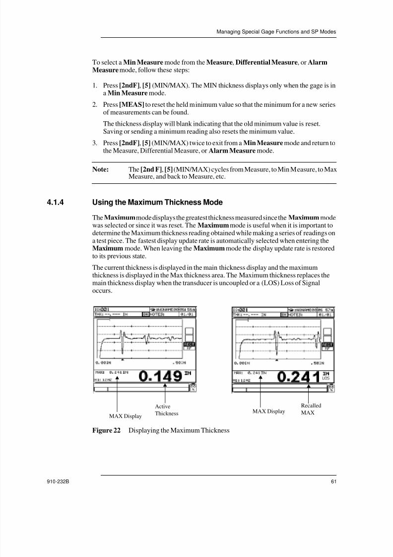
7/23/2019 Panametrics 25HP Plus Manual
http://slidepdf.com/reader/full/panametrics-25hp-plus-manual 61/230
Managing Special Gage Functions and SP Modes
910-232B 61
To select a Min Measure mode from the Measure, Differential Measure, or AlarmMeasure mode, follow these steps:
1. Press [2ndF], [5] (MIN/MAX). The MIN thickness displays only when the gage is ina Min Measure mode.
2. Press [MEAS] to reset the held minimum value so that the minimum for a new seriesof measurements can be found.
The thickness display will blank indicating that the old minimum value is reset.Saving or sending a minimum reading also resets the minimum value.
3. Press [2ndF], [5] (MIN/MAX) twice to exit from a Min Measure mode and return tothe Measure, Differential Measure, or Alarm Measure mode.
Note: The [2nd F], [5] (MIN/MAX) cycles from Measure, to Min Measure, to MaxMeasure, and back to Measure, etc.
4.1.4 Using the Maximum Thickness Mode
The Maximum mode displays the greatest thickness measured since the Maximum modewas selected or since it was reset. The Maximum mode is useful when it is important todetermine the Maximum thickness reading obtained while making a series of readings ona test piece. The fastest display update rate is automatically selected when entering theMaximum mode. When leaving the Maximum mode the display update rate is restoredto its previous state.
The current thickness is displayed in the main thickness display and the maximumthickness is displayed in the Max thickness area. The Maximum thickness replaces themain thickness display when the transducer is uncoupled or a (LOS) Loss of Signal
occurs.
Figure 22 Displaying the Maximum Thickness
MAX Display
Active
Thickness MAX DisplayRecalled
MAX

7/23/2019 Panametrics 25HP Plus Manual
http://slidepdf.com/reader/full/panametrics-25hp-plus-manual 62/230
62 Model 25HP PLUS
Note: In some situations, you can capture a false minimum reading when thetransducer is lifted from the test piece. This is possible when using excesscouplant, particularly on smooth surfaces, causing the gage to read thethickness of a couplant drop as the transducer is lifted. To avoid this
problem, use the Freeze function in conjunction with the MinimumThickness mode to freeze the waveform prior to uncoupling the transducer.Once the transducer is uncoupled and free of couplant, press [FREEZE]again to unfreeze the display and recall the minimum thickness andwaveform.
To select a Maximum Measure mode from the Measure, Differential Measure, orAlarm Measure mode, follow these steps:
1. Press [2ndF], [5] (MIN/MAX) twice. The Max thickness display shows when thegage is in a Max Measure mode and the thickness display shows the actual measuredthickness.
2. Press [MEAS] to reset the held Maximum value so that the Maximum for a new seriesof measurements can be found.
The thickness display will blank indicating that the old Maximum value is reset.Saving or sending a Maximum reading also resets the Maximum value.
3. Press [2ndF], [5] (MIN/MAX) to exit from a Max Measure mode and return to theMeasure, Differential Measure, or Alarm Measure mode.
Note: The [2nd F], [5] (MIN/MAX) cycles from Measure, to Min Measure, to MaxMeasure, and back to Measure, etc.
4.1.5 Managing High/Low Alarms
The Model 25HP PLUS has two different alarm modes: Standard Alarm and PreviousThickness Alarm. These alarms are audible beeps that warn you when measurements arebelow or above the alarm set points.
4.1.5.1 Activating the Standard Alarm
The Standard Alarm feature lets you view and change the Low Alarm Reference Value,High Alarm Reference Value, and to turn the visual and audible alarm functions ON/OFF.The Alarm Reference Values are thickness set points that have the current gage units andresolution. When an Alarm Measure mode is selected, the alarm condition occurs when
any displayed reading (either actual, minimum, or maximum) is either less than the LowAlarm Reference Value or greater than the High Alarm Reference Value.
The alarm condition is indicated by a flashing alarm flag located in the Thickness displayarea and a repeated audible beep as shown in the figure below:
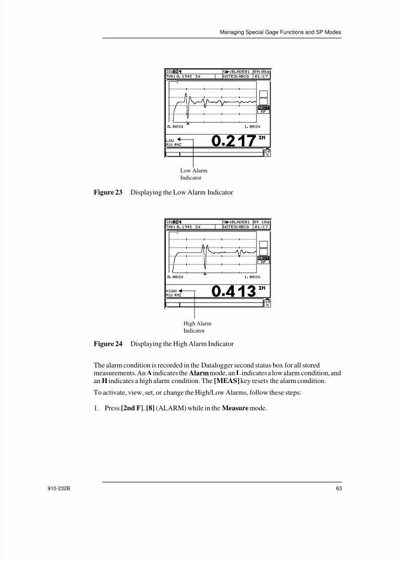
7/23/2019 Panametrics 25HP Plus Manual
http://slidepdf.com/reader/full/panametrics-25hp-plus-manual 63/230
Managing Special Gage Functions and SP Modes
910-232B 63
Figure 23 Displaying the Low Alarm Indicator
Figure 24 Displaying the High Alarm Indicator
The alarm condition is recorded in the Datalogger second status box for all storedmeasurements. An A indicates the Alarm mode, an L indicates a low alarm condition, andan H indicates a high alarm condition. The [MEAS] key resets the alarm condition.
To activate, view, set, or change the High/Low Alarms, follow these steps:
1. Press [2nd F], [8] (ALARM) while in the Measure mode.
Low Alarm
Indicator
High Alarm
Indicator

7/23/2019 Panametrics 25HP Plus Manual
http://slidepdf.com/reader/full/panametrics-25hp-plus-manual 64/230
64 Model 25HP PLUS
Figure 25 Selecting an Alarm Setting
2. Press [ ], [ ] or [ENTER] to highlight a setting to be changed (ENABLE, MODE, or
REF VALUES).
3. Press [ ], [ ] or [0]-[9] to change the highlighted setting.
4. Repeat from Step 1 to change another setting.
5. Press [MEAS] to return to the Measure mode with the displayed Alarm settings, orpress [2nd F], [MEAS] at any time to return to the Measure mode with the originalAlarm settings unchanged.
Note: Use the Alarm in conjunction with the Minimum/Maximum mode. Alarmreference values which were entered in one unit system are displayed as theequivalent value when the alternate units are selected.
4.1.5.2 Activating the Previous Thickness Alarm
Alarm on Previous thickness gives both an audio and visual alarm if the current thicknessvalue is outside the alarm set points when compared to the previous thickness value. Inorder to use this function, the previously stored file for an inspection must be sent to oralready exist on the Model 25HP PLUS. The alarm uses the previous thickness value as itsreference when determining if the current thickness is a high or low alarm condition.
The Alarm condition is indicated by a flashing alarm flag located in the thickness displayarea and repeated audio beeps. The Alarm condition is recorded in the datalogger secondstatus box for all stored measurements. An a indicates the Alarm mode, an l indicates alow alarm, and an h indicates a high alarm condition. The [MEAS] key resets the Alarmcondition.

7/23/2019 Panametrics 25HP Plus Manual
http://slidepdf.com/reader/full/panametrics-25hp-plus-manual 65/230
Managing Special Gage Functions and SP Modes
910-232B 65
Figure 26 Displaying the Previous Thickness Alarm
The Absolute Differential Alarm lets you set a Thickness Loss Alarm Value and a
Thickness Growth Alarm Value. These values are used to compare the current livethickness value to the previously stored thickness value at each ID# location within a file.If the current thickness value, when compared to the previous value, is outside the setlimits an alarm is indicated. If the thickness differential is greater than or equal to theThickness Loss Value a Low Alarm is indicated. If the thickness differential is greaterthan the Thickness Growth Value a High Alarm is indicated.
Example:
Thickness Loss Value: 0.050"
Thickness Growth Value: 0.005"
The Percent Differential Alarm lets you set a Percent Thickness Loss Alarm Value and aPercent Thickness Growth Alarm Value. These values are used to compare the currentthickness value to the previous thickness value at each ID# location in a file. If the currentthickness value is outside the set percent limits, when compared to the previous thicknessvalue, an alarm is indicated. If the percent thickness differential is greater than or equal tothe Percent Loss Value a Low Alarm is indicated. If the percent thickness differential isgreater than the Percent Growth Value a High Alarm is indicated.
PreviousValues
CurrentThickness
LowAlarm
HighAlarm
Calculations
0.300" 0.239" Yes No 0.300-0.239 > 0.050"
0.300" 0.316" No Yes 0.316-0.300 > 0.005"
0.300" 0.285" No No 0.300-0.285 < 0.050"
0.300" 0.302" No No 0.302-0.300 < 0.005"
Table 5 Calculating a Low/High Alarm

7/23/2019 Panametrics 25HP Plus Manual
http://slidepdf.com/reader/full/panametrics-25hp-plus-manual 66/230
66 Model 25HP PLUS
Example:
Percent Loss Value: 20%
Percent Growth Value: 5%
To activate, view, or change the percent thickness value, follow these steps:
1. Press [2nd F], [8] (Alarm) while in the Measure mode.
Figure 27 Entering Loss/Growth Values
2. Press [ ], [ ], or [ENTER] to highlight the Enable option.
3. Press [ ] or [ ] to turn the alarm on or off. If turning alarm off, then press [MEAS];if not press [ENTER].
Mode should now be highlighted.
4. Press [ ] or [ ] to select either Standard Alarm or Previous Thickness Alarm.For example, select PREV THK, and then press [ENTER].
PreviousValues
CurrentThickness
LowAlarm
HighAlarm
Calculations
0.300" 0.239" Yes No
0.300" 0.316" No Yes
0.300" 0.285" No No
0.300" 0.302" No No
Table 6 Calculating a Percent Thickness Alarm Value
0.300 0.239–
0.300--------------------------------- 100× 20%>
0.300 0.239–
0.300--------------------------------- 100× 5%>
0.300 0.285–
0.300--------------------------------- 100× 20%<
0.302 0.300–0.300
--------------------------------- 100× 5%<

7/23/2019 Panametrics 25HP Plus Manual
http://slidepdf.com/reader/full/panametrics-25hp-plus-manual 67/230
Managing Special Gage Functions and SP Modes
910-232B 67
DISPLAYED should now be highlighted.
5. Press [ ] or [ ] to select ABS DIFF (Absolute Differential) or % DIFF (PercentDifferential). Press [ENTER].
6. Enter Value for THK-LOSS (Thickness Loss Value) or % LOSS (Percent LossValue) using the numeric keys. Press [ENTER].
7. Enter THK-GROWTH (Thickness Growth Value) or % GROWTH (PercentGrowth Value). Press [MEAS].
Now the gage is in the Previous Thickness Alarm mode. When a reading triggers thealarm the gage responds with a visual alarm condition and an audible beep. Alarmconditions are stored in the datalogger with the stored data point.
4.1.6 Changing the Thickness Resolution
The resolution, i.e. the number of thickness value digits shown to the right of the decimalpoint, may be changed from the keyboard. This option may be useful in some applications
in which the extra precision of the last digit is not required, or where extremely roughoutside or inside surfaces make the last thickness display digit unreliable. The resolutionsare selectable; Standard (factory default) is 0.001" or 0.01mm; Low is 0.01" or 0.1mm.
• Standard (factory default): .001" or .01mm
• Low: .01" or .1mm
• High: .0001" or .001mm
The resolution selection affects all displays and data output of values with thickness units.This includes measured thickness, differential reference value, and alarm set points.
Note: The velocity is always reported with full five digit resolution.
To change the resolution while in the Measure mode, press [2ndF], [2] (RESOL). Thenew resolution is indicated by the position of the decimal point.
4.1.6.1 Velocity Resolution
The resolution, the number of digits shown to the right of the decimal point, can bechanged from the keyboard. This option is useful in some applications where the extraprecision of the last digit is not required. The resolution in velocity mode is selectable,standard 0.0001in/ µsec (00.001mm/ µsec), and low 0.001in/ µsec (00.01mm/ µsec).
4.1.6.2 Time of Flight ResolutionThe resolution, the number of digits shown to the right of the decimal point, is fixed at000.01µsec.
4.1.7 Using the Thickness Display Hold/Blank
While LOS (Loss of Signal) occurs, the displayed thickness and waveforms can be seteither to continue to show the last measured thickness (Hold mode), or to turn off

7/23/2019 Panametrics 25HP Plus Manual
http://slidepdf.com/reader/full/panametrics-25hp-plus-manual 68/230
68 Model 25HP PLUS
completely (Blank mode), depending if the Hold or the Blank display mode is selected.The Blank display mode is the default mode.
To change to the alternate thickness display mode from the Measure mode, press [2ndF],[7] (HOLD/BLK). The display shows an message indicating the current Hold/Blank
display condition.
4.1.8 Managing the Calibration Lock
The Calibration Lock feature lets you set the gage so that no calibration values (meaning,no parameters that can affect the value of the measurement) can be altered. These includeVelocity and Test block Zero. However, when the Calibration Lock condition is active,you can still view these values, change Measurement modes, and use the Dataloggerfunctions.
To activate the Calibration Lock, do the following:
Press [6] and [3] together while in a Measure mode.
A lock message appears briefly to indicate that the Calibration Lock is active.
If you press a locked key while the gage is in the Calibration Lock condition, a lockmessage opens.
To deactivate the Calibration Lock, do the following:
While in the Measure mode press [6] and [3] together again.
A beep indicates that the Calibration Lock is being disabled and the gage brieflydisplays the message CAL LOCK is off .
4.1.9 Freezing the Waveform
Pressing the [FREEZE] key stops the updating of the displayed waveform image andkeep the waveform and thickness on the display even after the transducer is moved orremoved. Frozen waveforms are indicated by a large F in the upper waveform status box.To return the display to an active mode press [FREEZE] again. The [MEAS] key alsoreturns the display to active mode. The [SAVE] key saves the data and returns the displayto active.
To Freeze the waveform and thickness display, follow these steps:
1. Press [FREEZE] while making a measurement. A large F in the upper waveformstatus box indicates a frozen waveform.
2. Press [FREEZE] again to unfreeze the waveform and thickness display.
Tip: The [MEAS] key and [SAVE] key also unfreeze the display.
4.1.10 Changing Rectification Modes
The Rectification mode is the way in which the ultrasonic echoes are represented on thewaveform display. The Rectification mode does not affect the thickness measurement inany way.

7/23/2019 Panametrics 25HP Plus Manual
http://slidepdf.com/reader/full/panametrics-25hp-plus-manual 69/230
Managing Special Gage Functions and SP Modes
910-232B 69
The default Rectification mode is called RF Waveform. Both positive and negative lobesare displayed in the RF Waveform, which gives the best overall representation of positionand magnitude for most gaging applications. The display indicates the rectification typeby an indicator “RF” located at the bottom right hand side of the waveform.
Other Rectification modes that are available are as follows:• Half Wave Negative: Shows negative echo lobes as positive and does not show the
positive lobes at all. An indicator, NEG, located at the bottom right of the waveform,indicates half wave negative.
• Half Wave Positive: Shows positive lobes but not negative lobes. An indicator, POS,located at the bottom right of the waveform, indicates half wave positive.
• Full Wave: Shows the negative portion of the echo folded around the baseline so thatboth positive and negative lobes are displayed.
To Change Rectification Modes, follow these steps:
1. Press [2nd F], [FREEZE] (RECT).
The Rectification mode changes to the next mode in the cycle: RF Full Wave - HalfWave Negative - Half Wave Positive - and back to RF - etc.
2. Press [2nd F], [FREEZE] (RECT) again if necessary to select the desired mode.
4.1.11 Selecting Metric Units
The [IN/MM] button lets you toggle between inches and millimeters. For example, if thegage is set to millimeters and you press [IN/MM], then the gage converts allmeasurements to inches. To reverse the conversion, simply press [IN/MM] again.
4.2 Operating SP Modes
The SP mode contains several adjustable parameters. To access the SP mode, press [2ndF], [0] on the keypad. Toggle to any of the options available such as Measurement,Communication, Diagnostics, Resets, or Clock, and press [ENTER].
Figure 28 Selecting an SP Mode
4.2.1 Managing the Measurement Setup Mode
The Measurement Setup mode is the most commonly usedSP mode. The MeasurementSetup mode lets you access a setup menu that controls global settings concerning the gage

7/23/2019 Panametrics 25HP Plus Manual
http://slidepdf.com/reader/full/panametrics-25hp-plus-manual 70/230
70 Model 25HP PLUS
measurement features. You can change any of the parameters from the available optionsin the Measurement Setup mode:
• Beeper
• Inactive Time
• Language
• Radix
• Waveform
• Backlight Mode
• Supervisor Lock
• Save Key
• MeasType
• ID Overwrite Protection
• Quick Setup
4.2.1.1 Managing the Beeper Tone
The Beeper Tone is used to signify when a key is pressed and also provide an audio signalduring alarm condition.
To enable or disable the Beeper function, follow these steps:
1. Press [2nd F], [0] (SP MODE).
2. Press [ ] or [ ] to highlight Measurement Setup. Press [ENTER].
3. Press [ ] or [ ] to highlight Beeper.
4. Use the [ ] or [ ] keys to select between Off (Beeper off) and On (Beeper on).
5. Press [MEAS] to return to the Measurement mode.
4.2.1.2 Managing Inactive Time
Normally the gage powers off automatically after about six minutes if no key is pressedand no measurement is made within that time. This is to prevent the battery from runningdown if the gage is left unattended for a long period of time without being powered off.The Auto Shut Off is selectable so you can choose between no auto power off and sixminute auto power off.
To enable or disable the Inactive Time function, follow these, steps:
1. Press [2nd F], [0] (SP MODE).
2. Press [ ] or [ ] to highlight Measurement Setup. Press [ENTER].
3. Press [ ] or [ ] to highlight Inactive Time.
4. Press [ ] or [ ] to select between off/on.

7/23/2019 Panametrics 25HP Plus Manual
http://slidepdf.com/reader/full/panametrics-25hp-plus-manual 71/230
Managing Special Gage Functions and SP Modes
910-232B 71
When Inactive Time is On, the unit powers off after 6 minutes of inactivity. WhenInactive Time is Off , the unit does not shut off until manually turned off using the[ON/OFF] key.
5. Press [MEAS] to return to the Measurement mode.
4.2.1.3 Managing Language Settings
The Model 25HP PLUS can currently be operated in English. German, French andSpanish will be added in the future. Contact Panametrics-NDTTM for further details.
4.2.1.4 Managing the Radix Point
The Model 25HP PLUS can display and store the thickness data with either a period or acomma as the Radix Point.
To Set the Radix Point, follow these steps:
1. Press [2nd F], [0].
2. Press [ ] or [ ] to highlight Measurement. Press [ENTER] and the followingscreen opens:
Figure 29 Selecting the Radix Point
3. Press [ ] or [ ] to highlight Radix.
4. Press [ ] and [ ] to change the setting to Period or Comma.
5. Press [MEAS] to exit.
4.2.1.5 Managing the Waveform Filled or Unfilled Trace
The Model 25HP PLUS can display the waveform trace as Filled or Unfilled.
Note: A filled waveform trace is only possible when the waveform rectification isset to full, halfwave negative or halfwave positive.

7/23/2019 Panametrics 25HP Plus Manual
http://slidepdf.com/reader/full/panametrics-25hp-plus-manual 72/230
72 Model 25HP PLUS
Figure 30 Displaying a Waveform Trace
To set the waveform trace parameter as Filled or Unfilled, follow these steps:
1. Press [2nd F], [0].
2. Press [ ] or [ ] to highlight Measurement. Press [ENTER] and the followingscreen opens:
Figure 31 Selecting a Waveform Trace Option
3. Press [ ] or [ ] to highlight Waveform.
4. Press [ ] and [ ] to change the setting to Fill or Unfill.
5. Press [MEAS] to exit.
4.2.1.6 Managing the Backlight
The display Backlight feature internally illuminates the liquid crystal display. This featurelets you view the display, which has excellent visibility in normal to high ambient lightconditions, in low to zero ambient light conditions. The Model 25HP PLUS has two
Unfilled Waveform Filled Waveform

7/23/2019 Panametrics 25HP Plus Manual
http://slidepdf.com/reader/full/panametrics-25hp-plus-manual 73/230
Managing Special Gage Functions and SP Modes
910-232B 73
Backlight modes; Normal and Auto. The Backlight mode is accessible through themeasurement setup by pressing [2nd F], [0].
To turn the Backlight on, follow these steps:
1. Press the key with the light bulb symbol.2. Press the light bulb key again to turn the Backlight off.
If the gage is in the Normal mode, the Backlight remains on until it is manually turnedoff. If the gage is in the Auto mode, the Backlight turns on when the Model 25HPPLUS is actively making measurements, and turn off 5 seconds after an (LOS) Loss ofSignal occurs. The Backlight key operates in every gage mode including the keyboardlock.
Note: Use the Backlight only when necessary. Both the battery operating time andthe long term brightness of the Backlight are substantially decreased whenthe Backlight is used continuously.
4.2.1.7 Managing the Supervisor Lock
The Supervisory Lock feature allows the gage to be locked from a higher level than theCalibration Lock located on the front of the keyboard. (See Managing the CalibrationLock on page 68). When this lock is enabled, no calibration values can be altered(meaning, no parameters that can affect the value of the measurement.) The locked valuesare:
• Velocity
• Test Block Zero
• Differential Reference Value• Alarm Set
• Transducer Adjustment Parameters
To enable the Supervisory Lock, follow these steps:
1. Press [2nd F], [0].
2. Press [ ] or [ ] to highlight Measurement. Press [ENTER] and the followingscreen opens:

7/23/2019 Panametrics 25HP Plus Manual
http://slidepdf.com/reader/full/panametrics-25hp-plus-manual 74/230
74 Model 25HP PLUS
Figure 32 Activating the Supervisor Lock
3. Press [ ] or [ ] to highlight Supv Lock.
4. Press [ ] and [ ] to select On or Off .
5. Press [MEAS] to exit.
4.3 Saving Key Selection
Either the displayed thickness value or both the thickness and waveform can be stored inthe Datalogger using the [SAVE] key. All of the appropriate calibration and setupparameters are also stored simultaneously. See Saving Data on page 138 for moreinformation.
4.3.1 MeasType
The 25HP PLUS can measure thickness, velocity, and time of flight. The MeasType(Measurement) type selection allows the user to select what type of measurement the gagewill display.
To select MEAS type, follow these steps:
1. Press [2ndF] [0] (Setup) and the SP Mode menu opens.
2. Press [ ] and [ ] to highlight the Measurement option. Press [ENTER].

7/23/2019 Panametrics 25HP Plus Manual
http://slidepdf.com/reader/full/panametrics-25hp-plus-manual 75/230
Managing Special Gage Functions and SP Modes
910-232B 75
Figure 33 Selecting Meas Type Parameter
3. Press [ ] and [ ] to change between THK (thickness), VEL (velocity), and TOF
(time of flight).
4.3.2 Operating the ID Overwrite Protection
ID Overwrite Protection is a function prompts you with a warning message every time youattempt to overwrite an existing measurement in the datalogger. You can activate thisfunction at any time. Once activated, a message prompt displays when an attempt is madeto save over an existing thickness reading/waveform. You can choose to Save Over (replace the existing stored measurement) or Cancel (leave the existing measurement inplace.)
To turn on ID Overwrite Protection, follow these steps:
1. Press [2nd F], [0].2. Press [ ] or [ ] to highlight Measurement. Press [ENTER] and the following
screen opens:
Figure 34 Activating ID Overwrite Protection
3. Press [ ] and [ ] to highlight ID Overwrite.

7/23/2019 Panametrics 25HP Plus Manual
http://slidepdf.com/reader/full/panametrics-25hp-plus-manual 76/230
76 Model 25HP PLUS
4. Press [ ] and [ ] to turn ID Overwrite Protection On or Off .
When ID Overwrite Protection is On, the following screen opens when you attempt tosave over an existing measurement.
Figure 35 Saving Measurements with Overwrite Protection activated
5. Press [ ] and [ ] to select Save or Cancel. Press [ENTER].
Selecting Save replaces the previous reading in the datalogger with the new reading.Selecting Cancel keeps the previous reading stored in the datalogger.
Note: The thickness reading and waveform is held on the display while you makethis selection.
4.3.2.1 Activating Quick SetupNormally, Custom Application Setups are changed by selecting the Application SetupList using [2nd F], [CAL] (SETUP), slewing down to the desired Setup Name, andpressing [MEAS]. This is adequate for the usual case in which setups are changedinfrequently. However, when it is necessary to change frequently between two or morecustom setups, a more direct short-cut procedure is available.
When this procedure (called Quick Setup) is enabled, a single keystroke (held for amoment to prevent errors) quickly switches to any of the first nine custom setups.
To enable the Quick Setup feature, follow these steps:
1. Press [2nd F], [0] (SP Mode). A list of special modes opens.
2. Press [ ], [ ], or [ENTER] to select Measurement. A list of items opens.
3. Press [ ] or [ ] to select Quick Setup.
4. Press [ ], [MEAS] to activate Quick Setup and return to the Measure mode.
To change the active application setup to any of the first nine custom setups when QuickSetup is enabled, do the following:

7/23/2019 Panametrics 25HP Plus Manual
http://slidepdf.com/reader/full/panametrics-25hp-plus-manual 77/230
Managing Special Gage Functions and SP Modes
910-232B 77
Press and hold any numeric key, [1] through [9], until the beep sounds (about 1.5seconds). The momentary message USER N is now active and appears on the secondstatus line, and the active setup is changed to the displayed name.
Note: USER-N refers to the Nth custom setup where N is the numeric key pressed.
You can use numeric keys repeatedly in this method to quickly move between setups.When preceded by the [2nd F] key, numeric keys always perform the indicated secondfunction, e.g. [2nd F], [5] selects MIN or MAX Measure mode even when Quick Setupis activated. Quick Setup remains enabled until disabled by following the proceduredescribed above.
4.3.3 Managing the Communication Mode
The Communication menu allows the gage and a computer to transfer data. In order forthis communication process to be successful, the parameters in the gage must match those
in the computer.
To change the communication parameters, follow these steps:
1. Verify the computer’s parameters for the baud rate, stop bits, and parity.
2. Press [2nd F], [0] (SP MODE). The following menu opens:
Figure 36 Selecting the Communications Mode
3. Press [ ] or [ ] to highlight the Communication option. Press [ENTER]. Thefollowing menu opens:

7/23/2019 Panametrics 25HP Plus Manual
http://slidepdf.com/reader/full/panametrics-25hp-plus-manual 78/230
78 Model 25HP PLUS
Figure 37 Changing the Communication Parameters
The current communication parameters appear. The settings available for eachparameter is as follows:
DBase Tracking: (On, Off)
Caliper Setting: (On, Off)
Baud Rate: (1200, 2400, 4800, 9600, or 19200)
Number of Stop Bits: (1 or 2)
Parity Bit: (None, Odd, or Even)
Comm Protocol: (Single or Multiple)
Output Format: (F1 to F10) (See Appendix E - Remote Control Via RS-232 onpage 213.)
Continuous Output: On, Off
4. Press [ ] or [ ] to change any of the parameters until the desired parameter ishighlighted.
5. Press [ ] or [ ] to change the parameter setting.
6. Exit this mode by highlighting the Previous Screen option and pressing [ENTER].
Tip: You can also exit this mode by pressing the [MEAS] key.
4.3.3.1 Using the Continuous Output Option
The Continuous Output option allows you to enable a special output mode, where the gagesends the current thickness reading at the display measurement update rate. Use thisfeature to send the current thickness reading to a computer or other device to continuously
monitor thickness changes. This feature is helpful if the Model 25HP PLUS is beingintegrated into an online thickness monitoring application. The output rate can be set to 4,8, 12, 16 and 20 outputs/sec. and is set using the Meas Rate Key. (See Using theMeasurement Display Update Rate on page 58.)
To activate the Continuous Output option do the following:
1. Press [2nd F], [0] (SP Mode).

7/23/2019 Panametrics 25HP Plus Manual
http://slidepdf.com/reader/full/panametrics-25hp-plus-manual 79/230
Managing Special Gage Functions and SP Modes
910-232B 79
2. Press [ ], [ ], or [ENTER] to select Communication.
3. Highlight Continuous Output. Press [ ] or [ ] to turn the function On or Off.(See Using the Continuous Output Option on page 78.)
Note: Only turn Continuous Output On to continuously send the active displaythickness through the RS-232 cable. It is important to turn Off this featurewhen Communicating with the WIN25DL PLUS interface program or whentrying to upgrade the 25HP PLUS operating software.
The output format for the Continuous Output data consists of the current live displayedthickness value and a Carriage Return <CR> then Line Feed<LF>. If the gage is in LOS(loss of signal) then “--.---” is sent indicating that the Measurement screen is blank. Thenumber of dashes after the decimal point is equal the current measurement resolution ofthe thickness display. An example of the continuous output format is listed below:
0.192<CR>,< LF>
0.192<CR>,< LF>0.191<CR>,< LF>
0.192<CR>,< LF>
0.191<CR>,< LF>
0.191<CR>,< LF>
0.191<CR>,< LF>
0.191<CR>,< LF>
--.---<CR>,< LF>
--.---<CR>,< LF>
0.191<CR>,< LF>
--.---<CR>,< LF>
4.3.3.2 Performing DBase Tracking
Use DBASE tracking when you want to duplicate a thickness inspection where the alarmset points values may be changing from one ID# to the next. The DBASE Tracking modeautomatically sets the Alarm Value to that which was used at the previous inspection. Touse this function you must download a file to the Model 25HP PLUS where the Alarm ismanually set for the different ID# locations or copy an existing file that has alarm settings.The measurement Alarms Settings values can automatically track to the values stored at
each ID number in the survey file. You can use the displayed ID numbers to guide youthrough the same series of measurements that were collected in the original survey file.Also, you can compare the current measurements with the previous thickness valuesdisplayed under the ID number at the top of the display.
If the downloaded or copied file do not have any Alarm set point values in the stored datafile at the current ID number, then the setups remain unchanged from the previous ID#.

7/23/2019 Panametrics 25HP Plus Manual
http://slidepdf.com/reader/full/panametrics-25hp-plus-manual 80/230
80 Model 25HP PLUS
Even if DBASE tracking is activate, you can override the alarm settings for the current IDnumber by manually changing the alarm values or by deactivating the DBASE Trackingfunctions.
To activate and deactivate DBASE Tracking , follow these steps:
1. Press [2nd F], [0] (SP Mode).
2. Press [ ], [ ], or [ENTER] to select Communication.
3. Press [ ], [ ] to highlight the DBASE Tracking option.
4. Press [ ]or [ ] to turn the function On or Off.
4.3.3.3 Caliper Settings
Only activate the Caliper setting when using the optional HPV/C Digital Caliper forvelocity measurements. Set the Caliper setting to On automatically sets thecommunication parameters for the digital caliper. Set the Caliper setting to Off for all
other RS232 communications (computer or printer.)
4.3.4 Managing the Gage Diagnostics Mode
The gage contains several Diagnostic Self Tests to help aid in localizing a suspectedhardware problem or to verify correct hardware operation. These tests can be performedfrom the keypad. To go to the Diagnostics menu, press [2nd F] [0] (SP MODE). Use the[ ] key to highlight Diagnostics, and press [ENTER]. A menu opens with the followingoptions.
• Keypad
• Video
• Hardware Status
• Hardware Control
• Error Status
4.3.4.1 Operating the Keypad Test
To operate the Keypad Test, follow these steps:
1. Press [ ] or [ ] to select Keypad.
2. Press [ENTER]. This displays a replica of the keypad on the display.
3. Test any key by pressing it on the keypad. If that specific key is working correctly, thegage beeps and that key is highlighted on the display.
Note: The [ON/OFF] key powers off the gage, and the [ENTER] key exits theKeypad Test mode.

7/23/2019 Panametrics 25HP Plus Manual
http://slidepdf.com/reader/full/panametrics-25hp-plus-manual 81/230
Managing Special Gage Functions and SP Modes
910-232B 81
4.3.4.2 Operating the Video Display Test
To operate the Video Display Test, follow these steps:
1. Press [ ] or [ ] to select Video.
2. Press [ENTER]. This test displays a darkened rectangle, which decreases in size. If atany time a break appears in the pattern, then there is a problem with the waveformdisplay. Otherwise, it is operating correctly.
4.3.4.3 Assessing the Hardware Status
To assess the Hardware status, follow these steps:
1. Press [ ] or [ ] to select Hardware Status.
2. Press [ENTER]. The gage displays many hardware calibration parameters and status.If the gage is functioning correctly, all parameters should display Passed.
4.3.4.4 Operating the Hardware Control
Note: Hardware Control is used by Panametrics-NDTTM repair technicians and,normally, should not be used.
To operate the Hardware Control, follow these steps:
1. Press [ ] or [ ] to select Hardware Control.
2. Press [MEAS] to return to the Measure mode.
4.3.4.5 Assessing Error Status
The Error Status is a log of any error condition that may have occurred during gageoperation. Pressing [MEAS] clears the error log and returns to the Measure mode.
4.3.5 Operating Gage Resets
The Model 25HP PLUS has four different resets designed to quickly restore the gage tothe default setup parameters.
• Measurement Reset
• Communication Reset
• DBase Reset
• Master Reset
Resets are useful whether you are new or experienced at operating the gage. These resetsprovide an efficient short-cut to a known configuration.

7/23/2019 Panametrics 25HP Plus Manual
http://slidepdf.com/reader/full/panametrics-25hp-plus-manual 82/230
82 Model 25HP PLUS
4.3.5.1 Performing a Measurement Reset
The Measurement Reset changes the measurement parameters to the factory defaultvalues. The default measurement parameters are listed below.
To perform the Measurement Reset, follow these steps:
1. Press [2nd F], [0] (SP MODE).
2. Press [ ] or [ ] to highlight the Resets option. Press [ENTER].
3. Press [ ] or [ ] to highlight Measurement Reset. Press [ENTER].
The gage prompts you to press the [ENTER] key to confirm the reset, or the [MEAS] key to escape and cancel Measurement Reset.
4. Press [MEAS] to return to the Measurement mode.
4.3.5.2 Performing a Communication Reset
The Communication Reset resets the Communication parameters to the factory defaultvalues. The default communication parameters are listed below.
DBase Tracking Off
Caliper Setting Off
Baud rate: 19200
Measurement Default Parameter
Measure mode withDifferential
Fast, Min, Max, and Alarms turned off
Material Velocity 0.22460 in/sec or 05.7048mm/sec the approximatevelocity of the included test blocks
Differential Reference Value 0.0 in or mm
Low Alarm Reference Value 0.0 in or mm
High Alarm Reference Value 25.0 in or 635.0mmCal keys Unlocked
Display Update Rate 4 per second
Zoom Off
Range Minimum range
Blank thickness display when LOS
Standard resolution, i.e. 0.001 in or 0.01mm
Table 7 Measurement Reset Default Settings

7/23/2019 Panametrics 25HP Plus Manual
http://slidepdf.com/reader/full/panametrics-25hp-plus-manual 83/230
Managing Special Gage Functions and SP Modes
910-232B 83
Stop Bits: 1
Parity: None
Comm Protocol: Multiple
Output Format: F1Continuous Output: Off
To perform the Communication Reset, follow these steps:
1. Press [2nd F], [0] (SP MODE).
2. Press [ ] or [ ] to highlight the Resets option. Press [ENTER].
3. Press [ ] or [ ] to highlight Communication Reset. Press [ENTER].
The gage prompts you to press either [ENTER] to confirm the reset or [MEAS] toterminate Communications Reset.
4. Press [MEAS] to return to the Measurement mode.
4.3.5.3 Performing a DBase Reset
The Dbase Reset deletes all stored data in the datalogger.
Caution: The Dbase Reset permanently deletes all stored thickness reading/waveformsthat are stored in the Model 25HP PLUS. However, this reset does not delete any storedtransducer setups.
To perform the Dbase Reset, follow these steps:
1. Press [2nd F], [0] (SETUP).
2. Press [ ] or [ ] to highlight the Resets option. Press [ENTER].
3. Press [ ] or [ ] to highlight Dbase Reset. Press [ENTER].
The gage prompts you to press either [ENTER] to confirm the reset or [MEAS] toterminate the Dbase Reset.
4. Press [MEAS] to return to the Measurement mode.
4.3.5.4 Performing a Master Reset
The Master Reset performs all of the Model 25HP PLUS’s resets. The Measurementparameters and Communication parameters are reset to their default values and the Dbaseis also be reset.
Caution: The Master Reset permanently deletes all stored thickness reading/waveformsthat are stored in the Model 25HP PLUS.
To perform the Master Reset, follow these steps:
1. Press [2nd F], [0] (SP MODE).
2. Press [ ] or [ ] to highlight the Resets option. Press [ENTER].
3. Press [ ] or [ ] to highlight Master Reset. Press [ENTER].

7/23/2019 Panametrics 25HP Plus Manual
http://slidepdf.com/reader/full/panametrics-25hp-plus-manual 84/230
84 Model 25HP PLUS
The gage prompts you to press either [ENTER] to confirm the reset or [MEAS] toescape and cancel Master Reset
4. Press [MEAS] to return to the Measurement mode.
4.3.6 Using the Clock
The Model 25HP PLUS has a built in clock for time and date. You can set the clock tospecific time zones in either a 12 or 24 hour mode. You can also set the date in StandardU.S. format (Month/Day) or International format (Day/Month). The following listincludes the parameters that are available:
• Mode (12 hour/24 hour)
• Hour
• Minutes
• AM/PM
• Mode (US/International)
• Month
• Day
• Year
To set the clock, follow these steps:
1. Press [2nd F], [0].
2. Press [ ] or [ ] to highlight the Clock option, and press [ENTER].
3. Press [ ], [ ], [ ], [ ], and [ENTER] keys to set the parameters to the desiredsettings.
4. Highlight Set and press [ENTER] to exit.
Highlight Cancel and press [ENTER] to terminate the new settings.

7/23/2019 Panametrics 25HP Plus Manual
http://slidepdf.com/reader/full/panametrics-25hp-plus-manual 85/230
Using Custom Setups
910-232B 85
5 Using Custom Setups
In addition to providing programmed standard transducer setups, the Model 25HP PLUS
permits you to create custom setups by changing a series of pulser/receiver and gatingparameters. Use custom setups when the measurement requirements of a particularapplication are not optimally met by one of the standard setups. In some cases, a Model25HP PLUS ships from the factory pre-programmed with one or more custom setups tomeet special customer requirements. However, you may want to create your own customsetups. Once adjustments are made, you can name and store these setup parameters in oneof the 35 user defined setup locations. This feature gives the Model 25HP PLUS theflexibility to change quickly between transducer and application setups by selecting thesetup name from a stored list or using the Quick setup recall feature.
Note: The adjustments described in this section should be made only by a qualifiedtechnician who is familiar with the basic theory of ultrasonic gaging and theinterpretation of ultrasonic waveforms.
Many of these adjustments are interactive, and all of them have an effect on themeasurement range and/or measurement accuracy of the Model 25HP PLUS. In mostcases, do not attempt adjustments without monitoring waveforms. Additionally, whenestablishing a custom setup for a specific application, it is essential to verify performanceon reference standards representing the material(s) and thickness range to measure.
Topics are as follows:
• Managing the Detect Mode Function
• Defining a Setup Name
• Defining a Probe Type
• Varying Pulser Power Effects
• Defining Maximum Gain
• Defining Initial Gain
• Defining TDG Slope
• Viewing the Main Bang Blank
• Viewing the Echo Window
5.1 Managing the Detect Mode Function
The Detect Mode function selects Mode 1, Mode 2, or Mode 3 measurements. SeeDtectMode and EchWindow Parameters on page 91 for further explanation.
Mode 1: Measures the time of flight between the Main Bang and the first backwall echousing a direct contact transducer.

7/23/2019 Panametrics 25HP Plus Manual
http://slidepdf.com/reader/full/panametrics-25hp-plus-manual 86/230
86 Model 25HP PLUS
Figure 38 Detect Mode 1
Mode 2: Measures the time of flight between the interface (or delay line) echo and the firstbackwall echo using a delay line or immersion transducer.
Figure 39 Detect Mode 2
Mode 3: Measures the time of flight between one backwall echo to the next backwall echousing a delay line or immersion transducer.
Main BangFirst Backwall
Main Bang
Interface
First Backwall

7/23/2019 Panametrics 25HP Plus Manual
http://slidepdf.com/reader/full/panametrics-25hp-plus-manual 87/230
Using Custom Setups
910-232B 87
Figure 40 Detect Mode 3
5.2 Defining a Setup Name
A user defined name has up to 16 alphanumeric characters used to name and describe thestored setup.
5.3 Defining a Probe Type
The probe type indicates the transducer type selected in the Active Setup. Each probe typeselected should match the frequency of the transducer being used for proper Pulser/
Receiver performance.
5.4 Varying Pulser Power Effects
You can adjust the excitation pulse (Main Bang) voltage in three steps of 30, 60, and 110Volts. Higher voltages may provide greater penetration at the expense of near surfaceresolution, especially in Mode 1, while lower voltages may provide better near surfaceresolution at the expense of penetration. For most applications the 110 Volt settingprovides the best signal-to-noise ratio for returning echoes. The Pulser Power does thefollowing:
• Indicates the voltage used to drive the transducer that is selected
• Affects the amount of energy going into the transducer and the size of the Initial Pulse
InterfaceFirst Backwall
First
Backwall
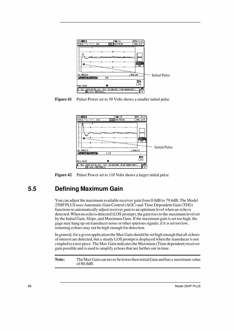
7/23/2019 Panametrics 25HP Plus Manual
http://slidepdf.com/reader/full/panametrics-25hp-plus-manual 88/230
88 Model 25HP PLUS
Figure 41 Pulser Power set to 30 Volts shows a smaller initial pulse
Figure 42 Pulser Power set to 110 Volts shows a larger initial pulse
5.5 Defining Maximum Gain
You can adjust the maximum available receiver gain from 0.0dB to 79.6dB. The Model25HP PLUS uses Automatic Gain Control (AGC) and Time Dependent Gain (TDG)functions to automatically adjust receiver gain to an optimum level when an echo isdetected. When no echo is detected (LOS prompt), the gain rises to the maximum level setby the Initial Gain, Slope, and Maximum Gain. If the maximum gain is set too high, thegage may hang up on transducer noise or other spurious signals; if it is set too low,returning echoes may not be high enough for detection.
In general, for a given application the Max Gain should be set high enough that all echoesof interest are detected, but a steady LOS prompt is displayed when the transducer is notcoupled to a test piece. The Max Gain indicates the Maximum (Time dependent) receivergain possible and is used to amplify echoes that are further out in time.
Note: The Max Gain can never be lower then initial Gain and has a maximum valueof 80.0dB.
Initial Pulse
Initial Pulse

7/23/2019 Panametrics 25HP Plus Manual
http://slidepdf.com/reader/full/panametrics-25hp-plus-manual 89/230
Using Custom Setups
910-232B 89
Figure 43 Maximum Gain
5.6 Defining Initial Gain
Initial Gain and TDG Slope are part of a Time Dependent Gain system that may be used tooptimize near-surface resolution while providing a higher maximum gain for thicker
samples. You can adjust the Initial Gain from 0dB to the maximum defined by the MaxGain setting. This parameter sets an upper limit on receiver gain in the vicinity of theexcitation pulse (Mode 1) or interface echo (Modes 2 and 3). By effectively making theexcitation pulse or interface echo smaller, the TDG system permits detection of echoesoccurring close to pulse or echo in time.
The TDG system is also used in measurements of highly scattering materials, such as castmetals and fiberglass, to minimize detection of scatter echoes occurring ahead of thebackwall. From the initial gain level, receiver gain slopes up to the maximum gain level atthe rate determined by the TDG Slope setting. The Initial Gain setting is most critical inapplications where minimum thickness measurements must be optimized, and shouldalways be set with the aid of a reference standard representing that minimum. In caseswhere the minimum thickness capability is less important than penetration, and scatter
echoes are not a problem, Initial Gain can be set equal to Max Gain. The Initial Gain doesthe following:
• Indicates the initial (time dependent) receiver gain currently selected
• Amplifies echoes that are close to the Main Bang or interface echoes
• Starts at Time Zero and extends to:
– the Main Bang Blank in Mode 1
– the end of the Interface Blank in Mode 2 and 3
Figure 44 Initial Gain
TDG SLOPE
Initial
TDG SLOPE
Initial
Max Gain
Time

7/23/2019 Panametrics 25HP Plus Manual
http://slidepdf.com/reader/full/panametrics-25hp-plus-manual 90/230
90 Model 25HP PLUS
5.7 Defining TDG Slope
The Time Dependent Gain (TDG) Slope function controls the rate at which the receivergain slopes up from the Initial Gain level to the Max Gain level. You can set the Slope from
0.0 to 26.5dB per microsecond. Generally, TDG Slope should be set as high as possible toreach maximum gain as quickly as possible without having the gage hang up on spurioussignals.
• Rate of increase of the receiver (Time dependent) Gain from Initial Gain to Max Gain
• Slope helps suppress reflections from grain structure or fibers
• Slope adjusts from 0.0dB to 26.52 dB/µSec
• Point in time that the Gain starts to slope is:
– the Main Bang Blank in Mode 1
– the End of the Interface Blank in Mode 2 and 3
Figure 45 TDG Slope
5.8 Viewing the Main Bang Blank
The Main Bang Blank is effectively a blank zone that protects the receiver from falsereadings generated by the Main Bang. This blank or dead zone (up to 18 microsecondsfrom the excitation pulse) prevents you from detecting echoes of the trailing edge of theexcitation pulse as if it were a backwall or interface echo. The Main Bang Blank indicatesthe point in time where the gage begins to search for echoes.
In Modes 2 and 3, the setting of the Main Bang Blank is not critical; set at some pointbetween the end of excitation pulse ringdown and the interface echo.
In Mode 1, however, the length of the Main Bang Blank determines the minimumthickness that can be measured, and it must be positioned with care after selecting theInitial Gain level. In Mode 1, set just past the Initial Pulse. If the Main Bang Blank is tooshort, then the gage hangs up on the excitation pulse and readings are not be possible. If the
Main Bang Blank is too long, then the minimum measurable thickness is unnecessarilyrestricted. Make sure that the Main Bang Blank is always set before the interface echofrom the shortest water path when using immersion transducers.
In general, set the Main Bang Blank just beyond the point where the gage hangs up, andtest with the transducer both coupled to and uncoupled from the test material to ensureaccurate measurements.
Max GainTDG SLOPE
Initial
Time

7/23/2019 Panametrics 25HP Plus Manual
http://slidepdf.com/reader/full/panametrics-25hp-plus-manual 91/230
Using Custom Setups
910-232B 91
Figure 46 Main Bang Blank position for Mode 1
Figure 47 Main Bang Blank position for Mode 2 and 3
5.9 Viewing the Echo Window
The Echo Window is the time interval in each Main Bang period during which the gage isenabled to detect Echoes. The Echo Window interval begins at the end of the Main BangBlank. The end of the Echo Window depends on the DtectMode and EchWindowparameters as shown in the following table:
Initial Pulse
Main Bang Blank
Main Bang Blank
Initial Pulse
DtectMode = 1 DtectMode = 2 or 3
Echo Window Starts: At end of Main BangBlank
At end of Main Blank
Table 8 DtectMode and EchWindow Parameters

7/23/2019 Panametrics 25HP Plus Manual
http://slidepdf.com/reader/full/panametrics-25hp-plus-manual 92/230
92 Model 25HP PLUS
In Mode 1, the Echo Window can usually be set to any value greater than the round-trippulse transit time in the thickest or slowest piece of material to be measured. The exactsetting is not critical as long as it is long enough to include the farthest echo of interest. InModes 2 and 3, the Echo Window is limited to the time interval between successiveinterface echoes. The end of the Echo Window must be set ahead of the second interfaceecho to prevent an incorrect detection, which in turn determines a maximum measurable
thickness for Mode 2 and Mode 3 setups. In applications involving Mode 2 and Mode 3 immersion measurements, the echo placement must apply throughout the range of waterpaths to be used.
Figure 48 Echo Window Setting for Mode 1
Echo Window Ends: EchWindow xµsecfollowing Main Bang
EchWindow xµsecfollowing the interface
blank
Note: xµsec where you set the x parameter.
DtectMode = 1 DtectMode = 2 or 3
Table 8 DtectMode and EchWindow Parameters (Continued)
Main Bang Blank
Initial Pulse
Backwall
Echo Window

7/23/2019 Panametrics 25HP Plus Manual
http://slidepdf.com/reader/full/panametrics-25hp-plus-manual 93/230
Using Custom Setups
910-232B 93
Figure 49 Echo Window Setting for Mode 2 and 3
5.9.1 Managing the P/R Config
The 25HP PLUS has three different Pulser Receiver settings, Pulse echo, Thru-Transmission and Pitch Catch. Each of these setting is described below.
Pulse Echo: Is used with one single element transducer located on one side of thematerial. The same transducer is used to both send and receive the ultrasonic signal. PulseEcho is the most commonly used Pulser Receiver configuration and can be used in Mode1, 2 and 3.
Figure 50 Pulse Echo Configuration
Thru-Transmission: Is used with two single element transducer located on either side ofthe material. One transducer is used to send the ultrasonic signal and the other is used toreceive the ultrasonic signal. This Pulser Receiver configuration is most commonly usedon very attenuating materials were it is not possible for the ultrasonic sound energy to
make a round trip. Thru- Transmission is limited to mode1 measurements.
Echo Window
Interface Blank
2nd Interface
Echo
Interface Echo
P/R

7/23/2019 Panametrics 25HP Plus Manual
http://slidepdf.com/reader/full/panametrics-25hp-plus-manual 94/230
94 Model 25HP PLUS
Figure 51 Thru-Transmission Configuration
Pitch Catch: Is used under two type of transducer configurations. The first is two singleelement transducer located on the same side of the material. One transducer is used to sendthe ultrasonic signal and the other is used to receive the ultrasonic signal. This PulserReceiver configuration is used for special application on very attenuating material wherethe user has accesses to only one side of the material.
Figure 52 Pitch Catch Configuration
5.9.1.1 Connector Configuration
In Pulse Echo P/R configuration, connect the transducer to the Channel #1 connector.
In Thru-Transmission and Pitch Catch P/R configuration, connect the receivingtransducer to Channel #1 connector and connect the pulsing transducer to Channel #2connector.
Figure 53 Identifying Connector Configuration
RP
P
R
Display Side
RS-232
Charger
Channel #1
Pulser/Receiver
Transducer
Connector
Channel #2 Pulser
Transducer Connector

7/23/2019 Panametrics 25HP Plus Manual
http://slidepdf.com/reader/full/panametrics-25hp-plus-manual 95/230
Using Custom Setups
910-232B 95
5.9.2 Echo 1 Detect and Echo 2 Detect
Echo 1 Detect and Echo 2 Detect select positive or negative polarity echo detection asdetermined by application requirements. Selection is dependant on mode of
measurement and type of test material.
Note: Positive and negative polarity refer to processed echoes displayed on thewaveform display.
Mode 1: Using contact transducers, Echo 1 is the backwall echo and Echo 2 is
not applicable. Echo 1 is normally negative, except when measuring materialof low acoustic impedance bonded to a material of high impedance (such asplastic or rubber over metal), where the echo is phase-reversed and positivedetection for Echo 1 is appropriate.
Mode 2: Using delay line or immersion transducers, Echo 1 is the interface
echo and Echo 2 is the backwall echo. Echo 1 is normally positive for highimpedance materials such as metals and ceramics, and negative for lowimpedance materials such as most plastics. Echo 2 is normally negative unlessthe backwall echo represents the sort of low-to-high impedance boundary
described above.
Mode 3: Using delay line or immersion transducers, Echo 1 is the interfaceecho and Echo 2 represents the backwall echoes. Since Mode 3 generally
involves measurement of high impedance materials, the general rule is to setEcho 1 positive and Echo 2 negative. In some special cases involving difficultgeometries, phase distortion may cause the positive side of the backwall echoes
to be better defined than the negative side; in such cases set Echo 2 positive.
Figure 54 Echo 1 Detection Negative

7/23/2019 Panametrics 25HP Plus Manual
http://slidepdf.com/reader/full/panametrics-25hp-plus-manual 96/230
96 Model 25HP PLUS
Figure 55 Negative Detection Steel Back by Air
Figure 56 Positive Detection Plastic Bonded to Steel
5.9.3 Interface Blank
Use Interface Blank in Modes 2 and 3 only. Interface Blank represents a blank or deadzone up to 20 microseconds in length that follows the leading edge of the interface echo.In Mode 2, the Interface Blank prevents detection of trailing lobes or cycles of theinterface echo, which might otherwise be detected as backwall echoes, resulting in a hang-up condition.
The Interface Blank should be set as short as possible to avoid unnecessarily restrictingminimum measurable thickness. The Initial Gain function often helps reduce interfaceecho amplitude and permit use of a shorter interface blank. Check Interface Blank settingswith the transducer both coupled to and uncoupled from the test material.
In Mode 3, the Interface Blank selects which pair of backwall echoes are measured. Inmost conditions, the Interface Blank would be set just short of the first backwall echo.However, as a practical matter, the first backwall echo from thin materials is oftendistorted or lost in the interface ringdown, and with some challenging geometries (such astight radii) later pairs of backwall echoes may be cleaner than early ones. In these cases, setthe Interface Blank to a length that insures detection of a clean and well-defined pair ofbackwall echoes, even if echoes are not the first two.
Echo 1 Detect
Positive
Echo 2 Detect
Negative

7/23/2019 Panametrics 25HP Plus Manual
http://slidepdf.com/reader/full/panametrics-25hp-plus-manual 97/230
Using Custom Setups
910-232B 97
Figure 57 Mode 2
Figure 58 Mode 3
5.9.4 Mode 3 Echo Blank
The function of Mode 3 Echo Blank in Mode 3 is analogous to that of Interface Blank inMode 2 or Main Bang Blank in Mode 1. This function creates a blank or dead zone up to
20 microseconds long following the leading edge of the first detected backwall echo, toprevent detection of trailing lobes or cycles of that echo and the resulting gage hang-up.Because Mode 3 Echo Blank limits minimum measurable thickness, set the controls asshort as possible; typically no longer than a few hundred nanoseconds. Special cases maybe an exception where mode conversion effects on curved samples cause significantspurious signals between legitimate echo peaks; in such cases set the Mode 3 Echo Blankas long as necessary to prevent detection of the spurious signals.
Gage Reading Trailing Edge of The Interface Echo
Interface Blank SetCorrectly
Gage Reading betweenBackwall 1 and 2
Interface Blank adjusted soGage will measure between
Backwall 2 and 3

7/23/2019 Panametrics 25HP Plus Manual
http://slidepdf.com/reader/full/panametrics-25hp-plus-manual 98/230
98 Model 25HP PLUS
Figure 59 Gage Hanging up on Trailing Edge of Backwall 1
Figure 60 M3Blank Set Properly
5.9.5 Making Setup Adjustment
To make setup adjustments, follow these steps:
1. Press [2ND F], (SETUP ADJ) and the gage displays the first setup adjustmentparameter just below the waveform area of the display.
Figure 61 Adjusting the Setup Parameter

7/23/2019 Panametrics 25HP Plus Manual
http://slidepdf.com/reader/full/panametrics-25hp-plus-manual 99/230
Using Custom Setups
910-232B 99
2. Press [ ] and [ ] to select which parameter to adjust.
3. Press [ ] or [ ] to change the value of the parameter.
5.9.6 Saving Setup Parameters
Once the proper adjustments are made, you can store the settings for a quick and easyrecall. The Model 25HP PLUS can store up to 35 custom setups in its internal memory.
To save setup parameters, follow these steps:
1. Make the appropriate changes to the setup parameters.
2. Press [RECALL SETUP] and [ENTER]. The Recall Setup Select screen opens.
Figure 62 Displaying Recall Setups
The changes that were made are located in the active setup.
3. Press [SAVE] and the Recall Setup Save screen opens.
Figure 63 Saving Recall Setups

7/23/2019 Panametrics 25HP Plus Manual
http://slidepdf.com/reader/full/panametrics-25hp-plus-manual 100/230
100 Model 25HP PLUS
4. Press [ ], [ ], [ ], [ ], and numeric keys to enter a name for the Custom Setup.Press [ENTER].
5. Press [ ] and [ ] to select a location to store the Custom Setup.
Setups named User-1 through User-35 are empty locations. Use caution whenselecting a location that already contains a custom setup because the new setup willreplace the old information.
6. Press [SAVE] to save the Custom Setup at the selected location. Pressing [MEAS] key the save function and returns to the Measure mode.

7/23/2019 Panametrics 25HP Plus Manual
http://slidepdf.com/reader/full/panametrics-25hp-plus-manual 101/230
Managing the Datalogger
910-232B 101
6 Managing the Datalogger
Two very useful and powerful features of the Model 25HP PLUS are the internal
datalogger and the two-way serial communication (RS-232) interface. The operation ofthe Datalogger and data transmission are discussed in this section. (See Appendix C -Serial Interface on page 187 for more information.)
An optional Bar Code Wand is available. (See Appendix F - Accessories and ReplacementParts on page 221.) This bar code wand directs measurement location ID numbers into thegage by simply scanning bar code labels. The Bar Code Wand plugs directly into the gageI/O connector.
Topics are as follows:
• Understanding the Datalogger
• Organizing the Datalogger
• Creating Data Files• Opening a File
• Copying a File
• Deleting a File
• Editing/Renaming a File
• Creating or Editing Comment Tables from a Computer
• Creating or Editing Comment Tables from the Model 25HP PLUS
• Saving Data
• Using the Review ID Mode
• Using the Edit ID Mode
• Erasing Data
• Using the Optional Bar Code Wand to Enter an ID Number
• Generating Reports
6.1 Understanding the Datalogger
The Model 25HP PLUS datalogger has an extensive built-in file and data managementsystem. Each thickness reading and/or waveform is stored and tagged with an
alphanumeric identification number and file name with descriptive fields. A completedescription of the measurement type, gage calibration and setup parameters is storedalong with each reading. The following are just a few datalogger functions:
• Store the waveform display with any thickness measurement
• Recall stored data to the gage displays, printed out, or sent to a computer
• Receive previously transmitted thickness and waveform data back from a computer

7/23/2019 Panametrics 25HP Plus Manual
http://slidepdf.com/reader/full/panametrics-25hp-plus-manual 102/230
102 Model 25HP PLUS
• View current datalogger settings while simultaneously taking measurements as,shown below:
Figure 64 Identifying Datalogger Settings
You can store either thickness measurements only or thickness measurements with anassociated waveform. When each measurement is stored, the gage also stores a completedescription of the measurement conditions with the measurement. The additional datastored with each thickness value includes:
• File Name
• File Header Data
• Identifier
• Units (in or mm)
• LOS (Loss of Signal)
• Differential Mode
• Differential Reference Value
• Alarm Mode
• Alarm Status
• Alarm Set Points
• Minimum or Maximum Mode
• Minimum or Maximum Reading• Velocity
• Resolution
• Transducer Setup Number and Information
Date/Time
Comment
Notes
File Name
ID#Previous
Thickness

7/23/2019 Panametrics 25HP Plus Manual
http://slidepdf.com/reader/full/panametrics-25hp-plus-manual 103/230
Managing the Datalogger
910-232B 103
When a waveform is stored, the following additional information is stored with it:
• Zoom Status
• Horizontal Axis Limits
• Detection Marker Position• Delay
• Range
• Rectification Mode
You can store a maximum of 18,000 thickness values without waveforms at any one timein the standard Model 25HP PLUS version. You can also store up to 1,700 thicknessvalues with waveforms. The memory is expandible in two increments of 1 MB each. Thefirst memory upgrade allows a maximum of 36,000 thickness values or 3,400 waveformswith thickness values. The second memory upgrade allows a maximum of 54,000thickness values or 5,100 waveforms with thickness values. Contact Panametrics-NDTTM for details about how to upgrade the memory.
6.2 Organizing the Datalogger
The Model 25HP PLUS datalogger is a flexible file based system. Every measurementstored into the datalogger is tagged with an file name and identification number (IDnumber). The file name and ID number may be thought of as the name of the place in thegage memory where the measurement data is stored. This description usually correspondsto the physical location numbers of each measurement point in the actual application. IDnumbers may also be associated with up to four Comments. The database can store a userdefined number of files with descriptive headers and each file has a user defined numberof identifiers.
When stored data is printed or loaded into a computer and later recalled back to the gage,each measurement is always uniquely identified by the file name and ID number where itwas initially stored.
6.2.1 File Name Structure
File names consist of up to eight alphanumeric characters. Allowable characters are asfollows:
0 1 2 3 4 5 6 7 8 9
A B C D E F G H I J K L M N O P Q R S T U V W X Y Z
- . #The total number of files is only limited by the number of identifiers. The file name islimited to eight DOS legal file name characters.
6.2.2 Identifier (ID Number) Structure
ID numbers consist of up to 16 alphanumeric characters. Allowable characters are asfollows:

7/23/2019 Panametrics 25HP Plus Manual
http://slidepdf.com/reader/full/panametrics-25hp-plus-manual 104/230
104 Model 25HP PLUS
0 1 2 3 4 5 6 7 8 9
A B C D E F G H I J K L M N O P Q R S T U V W X Y Z
space - . / , : # *
The allowable number of ID numbers within a file is dependent on the total number ofidentifiers in the datalogger. There are no restrictions on the use of any allowed characterat any position in an ID number except that you cannot use a space as either the first or lastcharacter of the ID number.
6.2.3 File Name Header Structure
The file name header is a series of fields designed for additional descriptive informationpertaining to a file. These fields include the following:
File Description
Inspector ID
Location-Note
Each field in the header consists of from 0 to 32 alphanumeric characters. Allowablecharacters are as follows:
0 1 2 3 4 5 6 7 8 9
A B C D E F G H I J K L M N O P Q R S T U V W X Y Z
space - . / , : # *
here are no restrictions on the use of any allowed character at any position in a header fieldexcept that you cannot use a space as either the first or last character of the ID number.
The following screen shows the fields that are available in the header for usercustomization:
Figure 65 Creating a File Name
6.2.4 Comment Structure
Use Comments to annotate individual measurement sites in the database for unusualmeasurement conditions. Save these notes with or without the thickness measurementdata as a permanent record of conditions encountered at the time of the survey.

7/23/2019 Panametrics 25HP Plus Manual
http://slidepdf.com/reader/full/panametrics-25hp-plus-manual 105/230
Managing the Datalogger
910-232B 105
Typical Comments are:
• THIN AREA
• THICK AREA
• OUT OF TOLERANCE• MIN THICKNESS
• MAX THICKNESS
• NO READING
• SEE WAVEFORM
A comment is a 16 character text note that can attach to a thickness reading in the database.The gage is capable of storing a maximum of 26 different comments per file, each ofwhich is identified by a comment code letter A, B, ...Z. Comments are user definable foreach file and can be alphanumeric. You can store 1 to 4 comments per thickness reading.Allowable characters are as follows:
0 1 2 3 4 5 6 7 8 9
A B C D E F G H I J K L M N O P Q R S T U V W X Y Z
space - . / , : # *
There are no restrictions on the use of any allowed character at any position in a commentexcept that you cannot use a space as either the first or last character of the ID number.
All comments stored with a reading appear as their associated letter code in the flagssection of the transmitted output. The full definition of each comment is written out in itsentirety in a comment table once transferred to a computer or printer.You can also viewComment code definitions on the gage display as shown below.
Figure 66 Creating a Note
(See Creating or Editing Comment Tables from the Model 25HP PLUS on page 135 forfurther instructions on using comments in the datalogger.)

7/23/2019 Panametrics 25HP Plus Manual
http://slidepdf.com/reader/full/panametrics-25hp-plus-manual 106/230
106 Model 25HP PLUS
6.3 Creating Data Files
Create Data Files for the Model 25HP PLUS datalogger from a computer or from withinthe Model 25HP PLUS.
Throughout this section there are references to use the Model 25HP PLUS StandardEditing Commands. These commands are described in the section below.
6.3.1 Using the Model 25HP PLUS Standard Editing Commands
To enter a number at any character location, do the following:
Press any numeric key to change the character at the cursor to the digit selected and thecursor automatically advances one position to the right.
To enter a letter or a symbol at any character location, follow these steps:
1. Press [ ] or [ ] to select a letter or punctuation mark.
2. Press and quickly release a slewing key to change the character by one value.
Hold a slewing key down to continuously cycle through the letters and punctuationmarks until the desired character is displayed.
Tip: The [ ] key moves forward from A to Z then * # : , / . - blank A etc. The [ ]key moves backward from - . / , # : * Z to A blank - etc. After selecting analpha character, press [ ] or [ ] to move the cursor position to anothercharacter.
Figure 67 Organization of Character Cycle

7/23/2019 Panametrics 25HP Plus Manual
http://slidepdf.com/reader/full/panametrics-25hp-plus-manual 107/230
Managing the Datalogger
910-232B 107
To insert a character at the cursor position, do the following:
Press [ZERO]. The character at the cursor and all those to the right moves oneposition to the right, making a space for a new character.
To delete the character at the cursor position, do the following:
Press [VEL]. The character at the cursor is deleted and any characters to the rightmoves left one position to fill-in the empty space.
6.3.2 Creating Files from a Computer (using the optional WIN25DL PLUS)
See the WIN25DL PLUS Interface Program Instruction Manual (part number 910-222)designed for use with the Model 25HP PLUS.
6.3.3 Creating Files from the Model 25HP PLUS
To create files from the Model 25HP PLUS, follow these steps:
1. Press [FILE]. The File Options menu opens:
Figure 68 Selecting the Create Option
2. Press [ ] and [ ] to highlight the Create option.
3. Press [ENTER]. The following menu opens:
Figure 69 Selecting a File Type

7/23/2019 Panametrics 25HP Plus Manual
http://slidepdf.com/reader/full/panametrics-25hp-plus-manual 108/230
108 Model 25HP PLUS
4. Press [ ] and [ ] to highlight a file type.
There are seven file types to choose from in the Model 25HP PLUS. (See sections6.3.2.1 - 6.3.2.7 for more information):
• Incremental
• Sequential
• Sequential with Custom Points
• 2-D Grid Matrix
• 2-D Grid Matrix with Custom Points
• 3-D Grid Matrix
• 3-D Custom
Note: As the list of file types is scrolled through, the right hand side of the displaydynamically responds showing the required entry parameters to create the
specific file types.
5. Highlight a file type and press [ENTER].
6.3.3.1 Incremental
After entering a starting ID number (up to 16 alphanumeric characters long) the gageautomatically increments to the subsequent ID numbers using the following incrementingrules:
• Only that portion of an ID number consisting of digits and letters (no punctuationmarks) beginning with the right-most character and extending leftward to the first
punctuation mark or to the left-most character (whichever comes first) can increment.• Digits are cycled 0, 1, 2, ..., 9, 0, etc. The 9 to 0 transition is done only after
incrementing the character to the left. Letters are cycled A, B, C, ..., Z, A, etc. The Z toA transition is done only after incrementing the character to the left. In either case, if there is no character to the left, or if the character to the left is a punctuation mark thenthe ID number cannot increment.
• If an ID number cannot increment, then after a reading is saved, an long error beepsounds and the momentary message “CANNOT INCREMENT” is shown on thewaveform display. Subsequent saves overwrite readings if you do not manuallychange the ID number first.
Note: To make the gage increment through a range of numbers several digits widewhile beginning with a single digit ID number, the maximum number of digit positions must be entered initially using leading zeroes. See Example 1.

7/23/2019 Panametrics 25HP Plus Manual
http://slidepdf.com/reader/full/panametrics-25hp-plus-manual 109/230
Managing the Datalogger
910-232B 109
Example 1: Some Automatically Generated Incremented ID Number Series
1. Initial 1 4. Initial 00012 0002
3 0003
. .
. .
. .
Limit 9 0009
0010
2. Initial ABC .
ABD .ABE .
. Limit 9999
.
. 5. Initial 1A
ABZ 1B
ACA 1C
ACB .
. .
. .. 1Z
Limit ZZZ 2A
2B
3. Initial ABC*12*34 .
ABC*12*35 .
ABC*12*36 .
. Limit 9Z
.
.
Limit ABC*12*99

7/23/2019 Panametrics 25HP Plus Manual
http://slidepdf.com/reader/full/panametrics-25hp-plus-manual 110/230
110 Model 25HP PLUS
To create an Incremental File, follow these steps:
1. Press [FILE]. The File Options menu opens.
2. Press [ ] and [ ] to highlight the Create option.The following screen opens:
Figure 70 Selecting an Incremental File Type
3. Select the Incremental option.
4. Enter the desired starting ID number for the data file. (See Using the Model 25HPPLUS Standard Editing Commands on page 106 for more detail about entering data.)Press [ENTER].
5. Press [ENTER]. The Continue option is highlighted.
6. Press [ENTER] to continue or press [ ] or [ ] to highlight the Cancel option ifyou want to cancel the operation.
Note: At any time, you can press [2nd F], [ ] or [2nd F], [ ] to tab between entryfields on the display. This is helpful if an error is made and you want to tabback to a previous field.
If you select the Continue option, the following screen opens:
Figure 71 Enter Incremental File Information

7/23/2019 Panametrics 25HP Plus Manual
http://slidepdf.com/reader/full/panametrics-25hp-plus-manual 111/230
Managing the Datalogger
910-232B 111
7. Enter a file name using the gages editing commands. A file name may consist of oneto eight DOS legal characters. Press [ENTER].
Enter File Description, Inspector ID, and Location-Note fields using the sameprocess. After each entry, press [ENTER] to tab to the next field.
8. Select On or Off for the Delete Protection option by pressing [ ] or [ ]. Press[ENTER].
On: Provides a warning whenever you try to delete the file.
Off: Allows the file to be deleted from the datalogger.
9. Select either the THK ,VEL, or TOF for the Meas Type option by pressing [ ] or [ ]. Press [ENTER].
THK: Designates a file to save thickness values.
VEL: Designates a file to save velocity values.
TOF: Designates a file to save Time of Flight values.
Note: In order to successfully create the file, a file name must be assigned using thegages editing commands. All other fields in this screen are optional.
10. Select the Done or Cancel option by pressing [ ] and [ ]. Press [ENTER].
Cancel: The gage terminates the file create process and returns to the Measure modewith the file and ID number unchanged. The datalogger contents remain unchanged.The file is not created.
Done: The gage returns to the Measure mode with this new file as the active file andthe first ID number in the file as the active ID number.
6.3.3.2 Sequential
A Sequential File is defined by a starting and an ending ID number. The resulting file isinclusive of the starting and ending points and all points in between.
Example 2: Start ID# = ABC123
End ID# = ABC135
Resulting file would contain the following list of ID numbers:
ABC123ABC124ABC125
.
.
.
ABC135
Example 3: Start ID# = XY-GY
End ID# = XY-IB
Resulting file would contain the following list of ID numbers:

7/23/2019 Panametrics 25HP Plus Manual
http://slidepdf.com/reader/full/panametrics-25hp-plus-manual 112/230
112 Model 25HP PLUS
XY-GYXY-GZXY-HA
.
.
.
XY-IB
To create an Sequential file, follow these steps:
1. Press [FILE]. The File Options menu opens.
2. Press [ ] and [ ] to highlight the Create option.The following screen opens:
Figure 72 Selecting a Sequential File Type
3. Select the Sequential option.4. Enter the desired starting ID number for the data file. (See Using the Model 25HP
PLUS Standard Editing Commands on page 106 for more detail about entering data.)Press [ENTER].
5. Enter an ending ID number. Press [ENTER].
The Continue option is highlighted.
6. Press [ENTER] to continue or press [ ] or [ ] to highlight the Cancel option ifyou wish to cancel the operation.
Note: At any time, you can press [2nd F], [ ] or [2nd F], [ ] to tab between entryfields on the display. This is helpful if an error is made and you want to tabback to a previous field.
If you select the Continue option, the following screen opens:

7/23/2019 Panametrics 25HP Plus Manual
http://slidepdf.com/reader/full/panametrics-25hp-plus-manual 113/230
Managing the Datalogger
910-232B 113
Figure 73 Entering Sequential File Information
7. Enter a file name using the gages editing commands. A file name may consist of one
to eight DOS legal characters. Press [ENTER].Enter File Description, Inspector ID, and Location-Note fields using the sameprocess. After each entry, press [ENTER] to tab to the next field.
8. Select On or Off for the Delete Protection option by pressing [ ] or [ ]. Press[ENTER].
On: Provides a warning whenever you try to delete the file.
Off: Allows the file to be deleted from the datalogger.
9. Select either the THK ,VEL, or TOF for the Meas Type option by pressing [ ] or [ ]. Press [ENTER].
THK: Designates a file to save thickness values.
VEL: Designates a file to save velocity values.
TOF: Designates a file to save Time of Flight values.
Note: In order to successfully create the file, a file name must be assigned using thegages editing commands. All other fields in this screen are optional.
10. Select the Done or Cancel option by pressing [ ] and [ ]. Press [ENTER].
Cancel: The gage terminates the file create process and returns to the Measure modewith the file and ID number unchanged. The datalogger contents remain unchanged.The file is not created.
Done: The gage returns to the Measure mode with this new file as the active file andthe first ID number in the file as the active ID number.
6.3.3.3 Sequential with Custom Point
A Sequential File with Custom Point is defined by a starting and an ending ID number plusa series of custom points. The resulting file is inclusive of the starting and ending points

7/23/2019 Panametrics 25HP Plus Manual
http://slidepdf.com/reader/full/panametrics-25hp-plus-manual 114/230
114 Model 25HP PLUS
and all points in between. In addition, multiple thickness readings per ID number locationare assigned using the assigned custom points.
Example 4: This example describes measurements along a pipe or tube where at eachID number location you can take measurements at Top, Bottom, Left and Right of the
pipe.Starting ID# = XYZ1267Ending ID# = XYZ1393
Custom Points = TOP
BOTTOMLEFTRIGHT
Resulting file would contain the following list of ID numbers:
XYZ1267TOP
XYZ1267BOTTOMXYZ1267LEFTXYZ1267RIGHTXYZ1268TOPXYZ1268BOTTOMXYZ1268LEFT.
.
.XYZ1393RIGHT
You can enter up to 31 custom points. The allowable length for each custom point dependson the ID number length defined in the starting and ending ID number fields. The totallength of the ID number plus the custom points cannot exceed 16 characters. For example:if the starting and ending ID numbers are seven characters long, as in the above example,the maximum allowable length for each custom point is nine (16-7=9).
To create a Sequential with Custom Point file, follow these steps:
1. Press [FILE]. The File Options menu opens.
2. Press [ ] and [ ] to highlight the Create option.The following screen opens:

7/23/2019 Panametrics 25HP Plus Manual
http://slidepdf.com/reader/full/panametrics-25hp-plus-manual 115/230
Managing the Datalogger
910-232B 115
Figure 74 Selecting a Sequential with Custom Point File Type
3. Select the Sequential with Custom Point option.
4. Enter the desired starting ID number for the data file. (See Using the Model 25HPPLUS Standard Editing Commands on page 106 for more detail about entering data.)Press [ENTER].
5. Enter an ending ID number. Press [ENTER].
The Custom Point selection box is highlighted.
6. Enter the first custom point using the editing controls. Press [ENTER].
The gage proceeds to the next field for custom point entry.
7. Enter the second custom point and press [ENTER]. Continue this process until alldesired custom points are entered.
When finished entering custom points, press [ENTER] on a blank entry. TheContinue option is highlighted.
8. Press [ENTER] to continue or press [ ] or [ ] to highlight the Cancel option ifyou want to cancel the operation.
Note: At any time, you can press [2nd F], [ ] or [2nd F], [ ] to tab between entryfields on the display. This is helpful if an error is made and you want to tabback to a previous field.

7/23/2019 Panametrics 25HP Plus Manual
http://slidepdf.com/reader/full/panametrics-25hp-plus-manual 116/230
116 Model 25HP PLUS
If you select the Continue option, the following screen opens:
Figure 75 Entering Sequential with Custom Point File Information
Continue with the following steps:
1. Enter a file name using the gages editing commands. A file name may consist of oneto eight DOS legal characters. Press [ENTER].
Enter File Description, Inspector ID, and Location-Note fields using the sameprocess. After each entry, press [ENTER] to tab to the next field.
2. Select On or Off for the Delete Protection option by pressing [ ] or [ ]. Press[ENTER].
On: Provides a warning whenever you try to delete the file.
Off: Allows the file to be deleted from the datalogger.
3. Select either the THK ,VEL, or TOF for the Meas Type option by pressing [ ] or [ ]. Press [ENTER].
THK: Designates a file to save thickness values.
VEL: Designates a file to save velocity values.
TOF: Designates a file to save Time of Flight values.
Note: In order to successfully create the file, a file name must be assigned using thegages editing commands. All other fields in this screen are optional.
4. Select the Done or Cancel option by pressing [ ] and [ ]. Press [ENTER].
Cancel: The gage terminates the file create process and returns to the Measure modewith the file and ID number unchanged. The datalogger contents remain unchanged.The file is not created.
Done: The gage returns to the Measure mode with this new file as the active file andthe first ID number in the file as the active ID number.
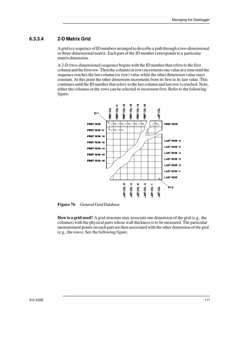
7/23/2019 Panametrics 25HP Plus Manual
http://slidepdf.com/reader/full/panametrics-25hp-plus-manual 117/230
Managing the Datalogger
910-232B 117
6.3.3.4 2-D Matrix Grid
A grid is a sequence of ID numbers arranged to describe a path through a two-dimensionalor three-dimensional matrix. Each part of the ID number corresponds to a particularmatrix dimension.
A 2-D (two-dimensional) sequence begins with the ID number that refers to the firstcolumn and the first row. Then the column (or row) increments one value at a time until thesequence reaches the last column (or row) value while the other dimension value staysconstant. At this point the other dimension increments from its first to its last value. Thiscontinues until the ID number that refers to the last column and last row is reached. Note,either the columns or the rows can be selected to increment first. Refer to the followingfigure.
Figure 76 General Grid Database
How is a grid used? A grid structure may associate one dimension of the grid (e.g., thecolumns) with the physical parts whose wall thickness is to be measured. The particularmeasurement points on each part are then associated with the other dimension of the grid(e.g., the rows). See the following figure.
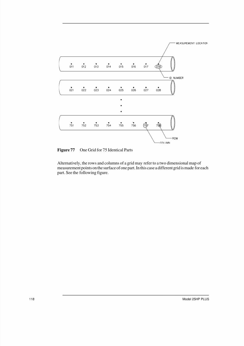
7/23/2019 Panametrics 25HP Plus Manual
http://slidepdf.com/reader/full/panametrics-25hp-plus-manual 118/230
118 Model 25HP PLUS
Figure 77 One Grid for 75 Identical Parts
Alternatively, the rows and columns of a grid may refer to a two dimensional map ofmeasurement points on the surface of one part. In this case a different grid is made for eachpart. See the following figure.

7/23/2019 Panametrics 25HP Plus Manual
http://slidepdf.com/reader/full/panametrics-25hp-plus-manual 119/230
Managing the Datalogger
910-232B 119
Figure 78 Different Named Grid for Each Part
To create a 2-D Grid file, follow these steps:
1. Press [FILE]. The File Options menu opens.
2. Press [ ] and [ ] to highlight the Create option.The following screen opens:
Figure 79 Selecting a 2D Grid File Type
Name: Elbow
Rows: 01 thru 10
Columns: A thru E
ID’s: Elbow/A0 thru Elbow/E10
Name: Tee
Rows: 1 thru 4
Columns: 1 thru 3
ID’s: Tee/11 thru Tee/34

7/23/2019 Panametrics 25HP Plus Manual
http://slidepdf.com/reader/full/panametrics-25hp-plus-manual 120/230
120 Model 25HP PLUS
3. Select the 2D Grid option.
4. Enter the desired starting ID number for the data file. (See Using the Model 25HPPLUS Standard Editing Commands on page 106 for more detail about entering data.)Press [ENTER].
5. Enter the desired ending column. Press [ENTER].
6. Enter the desired starting row for the grid. Press [ENTER].
7. Enter the ending row for the grid. Press [ENTER].
The Increment First By selection is highlighted.
8. Press [ ] or [ ] to select a column or a row for the increment method. Press[ENTER].
The Continue option is highlighted.
9. Press [ENTER] to continue or press [ ] or [ ] to highlight the Cancel option ifyou wish to cancel the operation.
Note: At any time [2nd F], [ ] or [2nd F], [ ] may be pressed to tab between entryfields on the display. This is helpful if an error is made and you want to tabback to a previous field.
If you select the Continue option, the following screen opens:
Figure 80 Entering 2D Grid File Information
Continue with the following steps:
1. Enter a file name using the gages editing commands. A file name may consist of oneto eight DOS legal characters. Press [ENTER].
Enter File Description, Inspector ID, and Location-Note fields using the sameprocess. After each entry, press [ENTER] to tab to the next field.
2. Select On or Off for the Delete Protection option by pressing [ ] or [ ]. Press[ENTER].
On: Provides a warning whenever you try to delete the file.

7/23/2019 Panametrics 25HP Plus Manual
http://slidepdf.com/reader/full/panametrics-25hp-plus-manual 121/230
Managing the Datalogger
910-232B 121
Off: Allows the file to be deleted from the datalogger.
3. Select either the THK ,VEL, or TOF for the Meas Type option by pressing [ ] or [ ]. Press [ENTER].
THK: Designates a file to save thickness values.
VEL: Designates a file to save velocity values.
TOF: Designates a file to save Time of Flight values.
Note: In order to successfully create the file, a file name must be assigned using thegages editing commands. All other fields in this screen are optional.
4. Select the Done or Cancel option by pressing [ ] and [ ]. Press [ENTER].
Cancel: The gage terminates the file create process and returns to the Measure modewith the file and ID number unchanged. The datalogger contents remain unchanged.The file is not created.
Done: The gage returns to the Measure mode with this new file as the active file andthe first ID number in the file as the active ID number.
6.3.3.5 2-D Matrix Grid with Custom Point
A grid is a sequence of ID numbers arranged to describe a path through a two-dimensionalor three-dimensional matrix. Each part of the ID number corresponds to a particularmatrix dimension. See 2-D Matrix Grid on page 117 for more information.
Custom points allow multiple readings per Grid ID number to be assigned.
Example 5:
Start Column AEnd Column J (Start Grid Coordinate = A01)
Start Row 01Start Row 17 (End Grid Coordinate = J17
Custom Points = LEFT
CENTERRIGHT
Resulting file would contain the following list of ID numbers:
A01LEFTA01CENTER
A01RIGHTA02LEFT...J17RIGHT
To create a 2-D Grid with Custom Points file, follow these steps:

7/23/2019 Panametrics 25HP Plus Manual
http://slidepdf.com/reader/full/panametrics-25hp-plus-manual 122/230
122 Model 25HP PLUS
1. Press [FILE]. The File Options menu opens.
2. Press [ ] and [ ] to highlight the Create option.The following screen opens:
Figure 81 Selecting a 2-D Grid with Custom Points File Type
3. Select the 2-D Grid with Custom Points option.
4. Enter the desired starting column for the grid. (See Using the Model 25HP PLUSStandard Editing Commands on page 106 for more detail about entering data.) Press[ENTER].
5. Enter the ending column. Press [ENTER].
6. Enter the starting row for the grid. Press [ENTER].
7. Enter the ending row for the grid. Press [ENTER].
The Custom Point selection box is highlighted.
Continue with the following steps:
1. Enter the first custom point using the editing controls. Press [ENTER]. The gageproceeds to the next line for custom point entry.
2. Enter the second custom point. Press [ENTER]. Continue this process until alldesired custom points are entered.
When finished entering custom points, press [ENTER] on a blank entry.
The Increment First By selection is highlighted.
3. Press [ ] or [ ] to select column, row or point as the first increment method. Press
[ENTER].
The Increment Second By selection is highlighted.
4. Press [ ] or [ ] to select column, row or point as the second increment method.Press [ENTER].
The Continue option is highlighted.

7/23/2019 Panametrics 25HP Plus Manual
http://slidepdf.com/reader/full/panametrics-25hp-plus-manual 123/230
Managing the Datalogger
910-232B 123
5. Press [ENTER] to continue or press [ ] or [ ] to highlight the Cancel option ifyou wish to cancel the operation.
Note: At any time [2nd F], [ ] or [2nd F], [ ] may be pressed to tab between entry
fields on the display. This is helpful if an error is made and you want to tabback to a previous field.
If you select the Continue option, the following screen opens:
Figure 82 Entering 2D Grid with Custom Points File Information
6. Enter a file name using the gages editing commands. A file name may consist of oneto eight DOS legal characters. Press [ENTER].
Enter File Description, Inspector ID, and Location-Note fields using the sameprocess. After each entry press [ENTER] to tab to the next field.
7. Select On or Off for the Delete Protection option by pressing [ ] or [ ]. Press[ENTER].
On: Provides a warning whenever you try to delete the file.
Off: Allows the file to be deleted from the datalogger.
8. Select either the THK ,VEL, or TOF for the Meas Type option by pressing [ ] or [ ]. Press [ENTER].
THK: Designates a file to save thickness values.
VEL: Designates a file to save velocity values.
TOF: Designates a file to save Time of Flight values.
Note: In order to successfully create the file, a file name must be assigned using thegages editing commands. All other fields in this screen are optional.
9. Select the Done or Cancel option by pressing [ ] and [ ] keys . Press [ENTER].
Cancel: The gage terminates the file create process and returns to the Measure modewith the file and ID number unchanged. The datalogger contents remain unchanged.The file is not created.

7/23/2019 Panametrics 25HP Plus Manual
http://slidepdf.com/reader/full/panametrics-25hp-plus-manual 124/230
124 Model 25HP PLUS
Done: The gage returns to the Measure mode with this new file as the active file andthe first ID number in the file as the active ID number.
6.3.3.6 3-D Matrix Grid
A 3-D Matrix Grid is a sequence of multi-part ID numbers arranged to describe a paththrough a three-dimensional matrix. Each part of the ID number corresponds to aparticular matrix dimension.
A 3-D (three-dimensional) sequence begins with the ID number that refers to the firstcolumn, the first row and the first point. Then the point (or column, or row) increments onevalue at a time until the sequence reaches the last point (or column, or row) value while theother two dimension values stay constant. At this point another dimension incrementsfrom its first to its last value. This continues until the ID number that refers to the lastcolumn, last row and last point is reached. You can select either the columns, rows orpoints to increment first.
How is a 3-D Grid Used? A three-dimensional grid structure may associate two-
dimensions of the grid (e.g., the columns and rows) with the physical coordinates on thepart whose wall thickness is to be measured. The particular measurement points on eachpart are then associated with the third dimension of the grid (e.g., the points). This scenarioallows multiple readings to be stored at each grid coordinate.
Example 6:
Start Column = AEnd Column = FStart Row = 1End Row = 4Start Point = XEnd Point = Z
Resulting file would contain the following list of ID numbers
A1XA1Y
A1ZA2X.
.
.A4Z
B1X
B1Y...F4Z

7/23/2019 Panametrics 25HP Plus Manual
http://slidepdf.com/reader/full/panametrics-25hp-plus-manual 125/230
Managing the Datalogger
910-232B 125
Note: You can select which dimension increments first, second and third. Theexample above assumes that you chose to increment the point first, the rowsecond and the column third.
To create a 3-D Grid with Custom Points file, follow these steps:
1. Press [FILE]. The File Options menu opens.
2. Press [ ] and [ ] to highlight the Create option.The following screen opens:
Figure 83 Selecting a 3-D Grid with Custom Points File Type
3. Select the 3-D Grid with Custom Points option.
4. Enter the desired starting column for the grid. (See Using the Model 25HP PLUSStandard Editing Commands on page 106 for more detail about entering data.) Press
[ENTER].5. Enter the desired ending column. Press [ENTER].
6. Enter the desired starting row for the grid. Press [ENTER].
7. Enter the ending row for the grid. Press [ENTER].
8. Enter the starting point for the grid. Press [ENTER].
9. Enter the ending point for the grid. Press [ENTER].
The Increment First By selection is highlighted
Continue with the following steps:
1. Press [ ] or [ ] to select column, row or point as the increment method. Press[ENTER].
The Increment Second By selection is highlighted
2. Press [ ] or [ ] to select column, row or point. Press [ENTER].
The Continue option is highlighted

7/23/2019 Panametrics 25HP Plus Manual
http://slidepdf.com/reader/full/panametrics-25hp-plus-manual 126/230
126 Model 25HP PLUS
3. Press [ENTER] to continue. Alternately, press [ ] or [ ] to highlight Cancel ifyou wish to cancel the operation.
Note: At any time [2nd F], [ ] or [2nd F], [ ] may be pressed to tab between entry
fields on the display. This is helpful if an error is made and you want to tabback to a previous field.
If you select the Continue option, the following screen opens:
Figure 84 Entering 3D Grid File Information
4. Enter a file name using the gages editing commands. A file name may consist of oneto eight DOS legal characters. Press [ENTER].
Enter File Description, Inspector ID, and Location-Note field using the same process.After each entry press the [ENTER] key to tab to the next field.
5. Select On or Off for the Delete Protection option by pressing [ ] or [ ]. Press[ENTER].
On: Provides a warning whenever you try to delete the file.
Off: Allows the file to be deleted from the datalogger.
6. Select either the THK ,VEL, or TOF for the Meas Type option by pressing [ ] or [ ]. Press [ENTER].
THK: Designates a file to save thickness values.
VEL: Designates a file to save velocity values.
TOF: Designates a file to save Time of Flight values.
Note: In order to successfully create the file, a file name must be assigned using thegages editing commands. All other fields in this screen are optional.
7. Select the Done or Cancel option by pressing [ ] and [ ]. Press [ENTER].
Cancel: The gage terminates the file create process and returns to the Measure modewith the file and ID number unchanged. The datalogger contents remain unchanged.The file is not created.

7/23/2019 Panametrics 25HP Plus Manual
http://slidepdf.com/reader/full/panametrics-25hp-plus-manual 127/230
Managing the Datalogger
910-232B 127
Done: The gage returns to the Measure mode with this new file as the active file andthe first ID number in the file as the active ID number.
6.3.3.7 3-D Custom
A 3-D custom file is a special file type designed for 3-D file application where two of thedimensions are user defined custom lists. This allows you to define the custom Row andCustom point as a list of user defined items. The first dimension is the column referring toa starting and ending vertical column. The second dimension is the Custom Row referringto a user defined custom list of rows. The third dimension is the Custom Point referring toa user defined custom list of points. When these three dimension are defined, the result isa single ID number formed to precisely identify the exact location for each thicknessreading:
Example 7:
ColumnStart column = 01
End column = 10
Custom Row = (TOP, Middle, Bottom)Custom Point = LEFT and RightIncrement first by Custom Point and Second by Column
The resulting file would contain the following list of ID numbers:01TOP-LEFT01TOP-RIGHT02TOP-LEFT02TOP-RIGHT
03TOP-LEFT03TOP-RIGHT...
10BOTTOM-RIGHT
To create a 3-D Custom file, follow these steps:
1. Press [FILE]. The File Options menu opens.
2. Press [ ] and [ ] to highlight the Create option.The following screen opens:

7/23/2019 Panametrics 25HP Plus Manual
http://slidepdf.com/reader/full/panametrics-25hp-plus-manual 128/230
128 Model 25HP PLUS
Figure 85 Selecting a 3-D Custom File Type
3. Select the 3-D Custom option.
4. Enter the desired starting column number for the grid. (See Using the Model 25HPPLUS Standard Editing Commands on page 106 for more detail about entering data.)Press [ENTER].
5. Enter the desired ending column number. Press [ENTER].
The Custom Row selection box is highlighted.
6. Enter the first custom row using the editing controls. Press [ENTER].
The gage proceeds to the next line for custom row entry.
7. Edit the second custom row and press [ENTER].
Continue this process until all desired custom rows have been entered. When finished
entering custom rows press [ENTER] on a blank entry.The Points selection box is highlighted.
8. Enter the first desired Custom Point using the editing controls. Press [ENTER].
The gage proceeds to the next line for point entry.
9. Edit the second point and press [ENTER].
Continue this process until all desired points have been entered. When finishedentering points press [ENTER] on a blank entry.
The Increment First By selection is highlighted.
Continue with the following steps:
1. Press [ ] or [ ] to select row, column or point as the increment method. Press[ENTER].
The Increment Second By selection is highlighted.
2. Press [ ] or [ ] to select row, column or point. Press [ENTER].
The Continue option is highlighted.

7/23/2019 Panametrics 25HP Plus Manual
http://slidepdf.com/reader/full/panametrics-25hp-plus-manual 129/230
Managing the Datalogger
910-232B 129
3. Press [ENTER] to continue or press [ ] or [ ] to highlight the Cancel option ifyou wish to cancel the operation.
Note: At any time [2nd F], [ ] or [2nd F], [ ] may be pressed to tab between entry
fields on the display. This is helpful if an error is made and you want to tabback to a previous field.
If you select the Continue option, the following screen opens:
Figure 86 Entering 3-D Custom File Information
4. Enter a file name using the gages editing commands. A file name may consist of oneto eight DOS legal characters. Press [ENTER].
Enter File Description, Inspector ID, and Location-Note field using the same process.After each entry press [ENTER] to tab to the next field.
5. Select On or Off for the Delete Protection option by pressing [ ] or [ ]. Press[ENTER].
On: Provides a warning whenever you try to delete the file.
Off: Allows the file to be deleted from the datalogger.
6. Select either the THK ,VEL, or TOF for the Meas Type option by pressing [ ] or [ ]. Press [ENTER].
THK: Designates a file to save thickness values.
VEL: Designates a file to save velocity values.
TOF: Designates a file to save Time of Flight values.
Note: In order to successfully create the file, a file name must be assigned using thegages editing commands. All other fields in this screen are optional.
7. Select the Done or Cancel option by pressing [ ] and [ ]. Press [ENTER].
Cancel: The gage terminates the file create process and returns to the Measure modewith the file and ID number unchanged. The datalogger contents remain unchanged.The file is not created.

7/23/2019 Panametrics 25HP Plus Manual
http://slidepdf.com/reader/full/panametrics-25hp-plus-manual 130/230
130 Model 25HP PLUS
Done: The gage returns to the Measure mode with this new file as the active file andthe first ID number in the file as the active ID number.
6.4 Opening a FileUse the File Open function to retrieve a file stored in the datalogger and mark it as theactive file in the Measure mode.
To open a File, follow these steps:
1. Press [FILE]. The File Options menu opens.:
Figure 87 Selecting Open Option
2. Highlight the Open option by pressing [ ] and [ ]. Press [ENTER]. The followingscreen opens:
Figure 88 Opening a File
3. Press [ ] and [ ] to highlight the name of a file to open. Press [ENTER].
The Open option is highlighted.

7/23/2019 Panametrics 25HP Plus Manual
http://slidepdf.com/reader/full/panametrics-25hp-plus-manual 131/230
Managing the Datalogger
910-232B 131
Note: When scrolling through the file names, a descriptive header for thehighlighted file name appears on the lower section of the display. Thisinformation can assist in selecting the proper file if you are uncertain of theexact file name.
4. Press [ENTER] to confirm opening the file. If you want to terminate the action press[ ] or [ ] to highlight the Cancel option. Press [ENTER].
If you select the Open option, the gage returns to the Measure mode with the selectedfile as the active file and the ID number is set to the first ID number in the file.
6.5 Copying a File
You can duplicate a file that already exists in the datalogger by using the File Copyfunction. This function provides two options:
• Copy the entire file including stored thickness data
• Copy the file ID number structure only
The File Copy function is useful when a new file needs to be created with the exact samestructure as a previous file.
To copy a file, follow these steps:
1. Press [FILE]. The File Options menu opens.
Figure 89 Selecting the Copy Option
2. Press [ ] and [ ] to highlight the Copy option. Press [ENTER]. The following menuopens:

7/23/2019 Panametrics 25HP Plus Manual
http://slidepdf.com/reader/full/panametrics-25hp-plus-manual 132/230
132 Model 25HP PLUS
Figure 90 Copying a File
3. Press [ ] and [ ] to highlight the name of the file that the new file is being copied
from. Press [ENTER].4. Use the Model 25HP PLUS editing controls to input the name of the new file being
created. Press [ENTER].
The Include Thickness Data? field is highlighted.
5. Press [ ] and [ ] keys to choose Yes or No. Press [ENTER].
This selection determines if previously stored thickness readings from the original fileare copied into the new file. If you select No, the ID Numbers are copied, but thethickness field is left blank.
The Copy option is highlighted.
6. Press [ENTER] to confirm the File Copy.
If you wish to terminate the File Copy, press [ ] or [ ] to highlight the Cancel option and press [ENTER].
7. Use the File Open commands to activate the newly copied file. (See Opening a File onpage 130.)
6.6 Deleting a File
The File Delete function is used to Erase files from the datalogger memory.
Note: Once a file is deleted there is no way to recover any information that wasonce contained in that file unless it has previously been copied to another fileor transferred to a printer or computer.
There are two methods for deleting a file.
To delete a file stored in the Model 25HP PLUS, follow these steps:
1. Press [FILE]. The File Options menu opens.

7/23/2019 Panametrics 25HP Plus Manual
http://slidepdf.com/reader/full/panametrics-25hp-plus-manual 133/230
Managing the Datalogger
910-232B 133
Figure 91 Selecting the Delete Option
2. Press [ ] and [ ] to highlight the Delete option. Press [ENTER]. The followingmenu opens:
Figure 92 Deleting a File
3. Press [ ] and [ ] to highlight the name of a file to delete. Press [ENTER].The Delete option is highlighted.
Note: When scrolling through the file names, a descriptive header for thehighlighted file name appears on the lower section of the display. Thisinformation can assist in selecting the proper file if you are uncertain of theexact file name.
4. Press [ENTER] to confirm erasing all data and file structure. If you wish to terminatethis process press [ ] or [ ] to highlight the Cancel option and press [ENTER].
To delete an active file, follow these steps:
1. Press [2nd F], [FILE] (CLR MEM). The ID - Range CLR screen opens:

7/23/2019 Panametrics 25HP Plus Manual
http://slidepdf.com/reader/full/panametrics-25hp-plus-manual 134/230
134 Model 25HP PLUS
Figure 93 Deleting an Active File
2. Use the editing function to define the beginning ID location. Press [ENTER].
3. Use the editing function to define the ending ID location. Press [ENTER].
4. Press [ ] or [ ] to select the Delete option and press [ENTER].
6.7 Editing/Renaming a File
The File Edit-Rename function is used to change/edit one or all of the following fields ina file:
• File Name
• File Description
• Inspector ID
• Location-Note
• Delete Protection (On/Off)
This function does not let you edit the File type and is not used for editing individualMeasurement Identifiers or actual Thickness Readings.
1. Press [FILE]. The File Options menu opens.
Figure 94 Selecting the Edit-Rename Option
2. Press [ ] and [ ] to highlight the Edit-Rename option. Press [ENTER]. The File Edit-Rename screen opens:

7/23/2019 Panametrics 25HP Plus Manual
http://slidepdf.com/reader/full/panametrics-25hp-plus-manual 135/230
Managing the Datalogger
910-232B 135
Figure 95 Entering New File Information
3. Press [ ] and [ ] to highlight the name of the file to edit or rename. Press [ENTER].
You can now edit the fields in the lower section of the display with the exception of theFile Type. The first field highlighted is the file name field. Edit this field using theModel 25HP PLUS Standard Editing Controls. (See Using the Model 25HP PLUSStandard Editing Commands on page 106.)
Note: While scrolling through the file names in the database, the lower section of the display will dynamically display the descriptive file header informationfor each file. This will assist in choosing the proper file if the file name isunknown.
4. Press [ENTER] after completing the edits. The File Description field for editing ishighlighted.
Continue this procedure until all desired fields are edited. At any time press [2nd F],[ ] and [2nd F], [ ] to move from one field to another.
6.8 Creating or Editing Comment Tables from aComputer
Using a computer to create comment tables is faster and easier than manually creatingthem on the Model 25HP PLUS. For details see the WIN25DL PLUS interface programinstruction manual designed for use with the Model 25HP PLUS.
6.9 Creating or Editing Comment Tables from the Model25HP PLUS
To create or edit comment tables, follow these steps:
1. Open the file that contains the Comment Table that you want to edit by using the FileOpen option. (See Opening a File on page 130.)

7/23/2019 Panametrics 25HP Plus Manual
http://slidepdf.com/reader/full/panametrics-25hp-plus-manual 136/230
136 Model 25HP PLUS
2. Press [2nd F], [ID#] (NOTE).
If there are no previous comments, the Notes screen opens.
Figure 96 Entering Information for the Comment Table
Note: If there are any previous comments, the screen may show those comments.
3. Press [ ] or [ ] to select the letter code for the comment you wish to program. Acomment is assigned a letter code A-Z.
4. Press [ ] and [ ] to activate the Edit mode. (See Using the Model 25HP PLUSStandard Editing Commands on page 106 for more detail about entering data.)
6.9.1 Deleting Comments from a Comment Table
To delete a particular comment text, follow these steps:
1. Press [2nd F], [ID#] (Note).
2. Press [ ] or [ ] until the desired comment to delete is highlighted.
3. Press [ ] or [ ] to enter Edit mode.
4. Press [ ] or [ ] to move the cursor.
5. Press [VEL] to delete the characters in the comment. The comment text will be erased.
Deleting comment text does not delete comment codes from the measurementdatabase.
Note: The text of comment codes that are already stored with measurements in thecurrent database should not be deleted since that destroys the meaning of thestored codes. You can delete the text for unused comment codes at any time.

7/23/2019 Panametrics 25HP Plus Manual
http://slidepdf.com/reader/full/panametrics-25hp-plus-manual 137/230
Managing the Datalogger
910-232B 137
6.9.2 Copying a Note
The Note Copy function can be used to copy a note table from one file to another file inthe Model 25HP PLUS. This is very useful when you are creating files from the Model
25HP PLUS and want to use a common note table.To Copy a Note Table, follow these steps:
1. Press [FILE]. The File Options menu opens.
2. Press [ ] and [ ] to highlight the Note-Copy option. Press [ENTER].
Figure 97 Selecting the Note-Copy Option
3. Press [ ] and [ ] to highlight the file (source file) that contains the Note Table youwant to copy. Press [ENTER].
Figure 98 Selecting a Note to Copy
4. Press [ ] and [ ] to highlight the file (destination file) that you want to copy. Press
[ENTER].

7/23/2019 Panametrics 25HP Plus Manual
http://slidepdf.com/reader/full/panametrics-25hp-plus-manual 138/230
138 Model 25HP PLUS
Figure 99 Copying a Note
5. Press [ ] and [ ] to select the Copy option or Cancel option. Press [ENTER].
Note: Copying a comment table to a file that has existing stored comments mayredefine the meaning of existing stored comments. For example, if A = HotSurfaces in the original comment table and you copy a comment table whereA = Painted Surfaces, it changes the definition of A, and thus changes themeaning of any previous stored A comments.
6.10 Saving Data
Store displayed thickness value or both the thickness and waveform in the datalogger
using the [SAVE] key. All of the appropriate calibration and setup parameters are alsostored simultaneously. (See Understanding the Datalogger on page 101 for a completedescription of what is stored in the datalogger.)
If a measurement is already stored at the current ID number, pressing [SAVE] overwritesthe old thickness reading with the current thickness reading unless the overwriteprotection feature is enabled. (See Operating the ID Overwrite Protection on page 75.)
If you do not want to save a measurement at a specific ID, press [SAVE] while nomeasurement is taken. The gage will store an LOS condition and —-.—- at the specific IDnumber.
6.10.1 Saving Thickness Readings
To save a thickness reading, do the following:
While the thickness value is being displayed, press [SAVE].
An audible beep indicates that the reading is saved. The displayed thickness value andsetup information is stored at the current ID number in the current file. If the thicknessdisplay is blank when [SAVE] is pressed, then “——-” is saved in place of a value.

7/23/2019 Panametrics 25HP Plus Manual
http://slidepdf.com/reader/full/panametrics-25hp-plus-manual 139/230
Managing the Datalogger
910-232B 139
The ID number is automatically updated to the next ID number in the sequence. The newID number is indicated on the display. If the ID number cannot be updated a long beepsounds and the gage displays a message explaining why the ID was unable to update. Inthis case, the ID number on the display remains unchanged.
6.10.2 Saving Thickness and Waveform
To save a thickness and waveform, do the following:
While the thickness value is displayed, press [2nd F], [SAVE].
An audible beep indicates that the reading is saved. The displayed thickness value,waveform and setup information are stored at the current ID number in the current file. Ifthe thickness display is blank when you press [SAVE], then “——-” is saved in place of avalue.
The ID number is automatically updated to the next ID number in the sequence. The newID number is indicated on the display. If the ID number cannot be updated a long beep
sounds and the gage displays a message explaining why the ID was unable to update. Inthis case, the ID number on the display remains unchanged.
6.10.3 Saving Comments
Up to four comments may be stored at each identifier within a file.
To save a comment, follow these steps:
1. Press [2nd F], [ID#] (Note). The Notes table opens, similar to the display shownbelow.
Figure 100 Selecting a Comment from the Notes Table
2. Press [ ] and [ ] to highlight the desired comment to be stored. Press [ENTER]. Theselected comment is marked with a square in the box to the left of the comment lettercode.
Repeat this step up to four comments.

7/23/2019 Panametrics 25HP Plus Manual
http://slidepdf.com/reader/full/panametrics-25hp-plus-manual 140/230
140 Model 25HP PLUS
3. Press [MEAS]. The next time [SAVE] is pressed these comment codes will be savedwith the thickness at the current ID number.
(See Creating or Editing Comment Tables from the Model 25HP PLUS on page 135for more information.)
Note: The comment codes are automatically untagged every time you press[SAVE]. Therefore, you must select the desired comment code before usingit.
6.11 Using the Review ID Mode
The review ID mode has three purposes:
• Review datalogger contents by scanning through stored ID locations in the active file.
• Move within the database and change the current ID location to any location thatalready exists in the database.
• Change the current ID location to any location that already exists in the database forthe purposes of editing that ID location.
To review stored thickness values and waveforms or move to an existing id location,follow these steps:
1. From the Measure mode, press [ID#]. The following data is displayed on the screen:
• Current ID Location
• Current File Name
• Stored Thickness Value• Stored Waveform (if any) with Status Flags (described in figure below)
• Stored Comments or Notes
Datalogger Flags: The area composed of four small boxes in the upper right corner ofthe waveform area is reserved for status flags describing the displayed storedthickness values. The flags are the same single letter abbreviations for status wordsthat are transmitted by the gage using the Sending commands. (See ManagingCommunications / Data Transfer on page 149.) The flags that are defined for each boxare described in the figure below.
The Review mode is indicated by ID Review section in the center of the display. Anexample is shown in the figure below:

7/23/2019 Panametrics 25HP Plus Manual
http://slidepdf.com/reader/full/panametrics-25hp-plus-manual 141/230
Managing the Datalogger
910-232B 141
Figure 101 Identifying the Review ID Mode
Measurements are disabled in this mode.
2. Press [ ] to display the next ID Location in the datalogger and its stored contents.
3. Press [ ] to display the previous ID Location and its stored contents.You can eitherpress [ ] and [ ] repeatedly or hold down either key to review the datalogger.
4. Press [2nd F], [ ] to jump to the last ID Location in the file. Press [2nd F], [ ] to jump the first ID Location in the file.
5. Press [ID#] at any time to edit the displayed ID Location. (See Using the Edit ID Mode
on page 141.)6. Press [MEAS] to return to the Measure mode with the current ID Location changed
to the ID Location selected in the ID Review mode.
7. Press [2nd F], [MEAS] to return to the Measure mode with the current ID numberunchanged. The current ID Location will be the last active ID Location in theMeasure mode.
6.12 Using the Edit ID Mode
The ID Edit mode is generally used for one of two purposes:
• To change the current ID Location to a different ID Location already in the database.This mode is useful when using a large database and it would take too long to locatethe desired ID using the [ ] and [ ] keys.
• To change the current ID Location to a new ID, which does not yet exist in thedatabase. This mode is useful when a user wishes to include additional measurementpoints to the active file. Additional ID Locations can be added anywhere in thedatabase (beginning, middle, end.)
ID Review Screen
M-MeasurementL-LOS Standard Mode
Differential Mode
D-Differential Moded -% Differential Mode
Standard Alarm
A-Alarm ModeH-High AlarmL-Low Alarm
Percent Previous Mode
p-Alarm Moder-Reduction Alarmg-Growth Alarm
Absolute Previous Alarm Mode
P-Alarm modeR-Reduction AlarmG-Growth Alarm
m-MINM-MAX
1-Mode 12-Mode 23-Mode 3

7/23/2019 Panametrics 25HP Plus Manual
http://slidepdf.com/reader/full/panametrics-25hp-plus-manual 142/230
142 Model 25HP PLUS
Note: No stored data is shown while in ID Edit mode and no measurements can bemade.
To use the ID Edit mode, follow these steps:
1. Press [ID#] from the Measure mode.
The current ID Location, including the stored thickness contents (if any), storedwaveform (if any), and stored comments/notes (if any), are displayed on the IDReview screen. (See Using the Review ID Mode on page 140.)
2. Use the ID Review mode techniques to select the ID Location to begin editing.
3. To enable the ID Edit mode, press [ID#] key again and the following editing screenopens:
An editing cursor (reverse video) appears on the first character of the displayed IDLocation, as shown on the above screen. (See Using the Model 25HP PLUS Standard
Editing Commands on page 106 for more detail about entering data.)
Choose one of the following three steps to exit editing at any time:
1. Press [MEAS] to return to the Measure mode with the Current ID Location modifiedas displayed.
If the edited ID is NOT in the database, the following screen opens:

7/23/2019 Panametrics 25HP Plus Manual
http://slidepdf.com/reader/full/panametrics-25hp-plus-manual 143/230
Managing the Datalogger
910-232B 143
Figure 102 Example of Screen if Edited ID is Not in the Database
2. Press [ ] or [ ] to select the Insert, Append, or Cancel option.
The Append option has the edited ID number appended to the end of the file.
The Insert option has the edited ID inserted after the current ID Location.
3. After pressing [SAVE], the sequence resumes at the previous current ID.
4. Press [ID#] to Return to the ID Review mode with the Displayed ID modified asedited. The ID Review mode is entered with the ID selected in the Edit mode.
5. Press [2nd F], [MEAS], at any time, to return to the Measure mode without changingthe Current ID Number. This terminates the edit process.
6.13 Erasing Data
Note: Data erased by the techniques below CANNOT be recovered.
6.13.1 Erasing Data in the Active/Open File
To erase a single measurement, follow these steps:
1. Press [ID#], from the Measure mode, to enter the ID Review mode. The current IDnumber is shown with its stored data.
2. Press [ ] and [ ] or the edit keys to change to the ID number to be erased. (See Usingthe Edit ID Mode on page 141.)
3. Press [2nd F], [FILE] (Clr Mem) to erase the data at the displayed ID number, thethickness value, the setup information, and the waveform. The displayed ID numberchanges to the next ID number in the sequence following the one erased.
Note: To replace a thickness reading it is easier to save a new measurement at thedesired ID from the Measure mode. If you do not want to save a

7/23/2019 Panametrics 25HP Plus Manual
http://slidepdf.com/reader/full/panametrics-25hp-plus-manual 144/230
144 Model 25HP PLUS
measurement at a specific ID, press the [SAVE] key from the Measuremode when you are not taking a measurement. This stores an LOS conditionand —-.—- at the specific ID number.
4. Press [MEAS] to return to the Measure mode.
Note: When deleting the ID number in Sequential or Incremental files, the IDnumber location are also deleted. In all file types, only the thickness/ waveform is deleted.
To erase a range of measurements, follow these steps:
1. Press [2nd F], [FILE] (CLR MEM) from the Measure mode.
2. Enter the starting range ID and ending range ID.
3. Press [ENTER].
4. Select the Delete or Cancel option and press [Enter].
6.13.2 Erasing a File
See Deleting a File on page 132.
6.13.3 Erasing the Entire Database
Caution:Erasing the entire Database erases all files and data contained in those files. Thedatalogger will be completely empty after this procedure.
1. Press [2nd F], [0] (SP MODE). The SP Mode menu opens:
Figure 103 Selecting the Resets Option
2. Press [ ] and [ ] to highlight the Resets option. Press [ENTER]. The followingscreen opens:

7/23/2019 Panametrics 25HP Plus Manual
http://slidepdf.com/reader/full/panametrics-25hp-plus-manual 145/230
Managing the Datalogger
910-232B 145
Figure 104 Selecting the DBase Reset Option
3. Press [ ] and [ ] to highlight the DBase Reset option. Press [ENTER]. Thefollowing screen opens:
Figure 105 Warning Message when Resetting DBase
4. Press [ENTER] to confirm, or press [MEAS] to abort DBASE Reset.
6.14 Using the Optional Bar Code Wand to Enter an IDNumber
Panametrics-NDTTM offers a non-contact Bar Code Wand for the Model 25HP PLUS (Part#36DLP/BCW). The purpose of using a Bar Code Wand is to provide a method for thegage to automatically edit the current ID number to match that of a bar code label.
To use the Bar Code Wand to enter an ID number, follow these steps:
1. Verify the communication parameters are set to the following values:
Baud Rate: 19200

7/23/2019 Panametrics 25HP Plus Manual
http://slidepdf.com/reader/full/panametrics-25hp-plus-manual 146/230
146 Model 25HP PLUS
Word Length:8
Parity: None
Stop Bits: 1
2. Plug the Panametrics-NDTTM Bar Code Wand into the RS-232 Connector on theModel 25HP PLUS.
3. Scan the Bar Code Wand on the special ID Code Label.
When using the non-contact wand, position the scanner over the bar code label (0.0 -2.00"or 0 - 50mm away from the label) and press the trigger button.
The ID number changes to the value coded on the label and the gage returns to theMeasure mode, ready to take a measurement.
4. Press [SAVE] to save a measurement.The current ID number is displayed in the IDsection of the screen (top left).
Note: Print labels on medium density 3 of 9 code. Consult Panametrics-NDT forfurther information on label requirements.
6.15 Generating Reports
The Model 25HP PLUS is capable of generating inspection data reports from within thegage without having to connect to a computer or printer. The following reports areavailable:
• File Summary with Statistics Report
• Min/Max Summary
• File Comparison Report
To generate a report, follow these steps:
1. Press [FILE]. The File Option menu opens:
Figure 106 Selecting the Reports Option
2. Press [ ] and [ ] to highlight the Reports option. Press [ENTER]. The followingmenu opens:

7/23/2019 Panametrics 25HP Plus Manual
http://slidepdf.com/reader/full/panametrics-25hp-plus-manual 147/230
Managing the Datalogger
910-232B 147
Figure 107 Selecting the File Summary with Stats Option
3. Press [ ] and [ ] to highlight the desired report format. Press [ENTER]. Choose
from the following reports:• Summary with Statistics Report
• Min/Max Summary
• File Compression.
If you select the Summary with Statistics Report option, the File Summary w/ Stats screen opens.
Figure 108 Selecting a File to View
1. Press [ ] and [ ] to highlight the desired file name.
2. Press [ENTER] to view the statistics.
If you select the Min/Max Summary option, the following screen opens.

7/23/2019 Panametrics 25HP Plus Manual
http://slidepdf.com/reader/full/panametrics-25hp-plus-manual 148/230
148 Model 25HP PLUS
Figure 109 Viewing File if Min/Max Summary is Selected
1. Press [ ] and [ ] to select the file and press [ENTER]. The minimum and maximumthickness location will be displayed.
2. Press [ ] and [ ] to slew through the minimum thickness location.
3. Press [ENTER] to highlight the maximum thickness locations.
4. Press [ ] and [ ] to slew through the maximum thickness location.
5. Press [2nd F], [ ] or [2nd F], [ ] to move between File Select, Min Thickness, andMaximum Thickness.
If File Comparison Report is chosen the following screen opens.
Figure 110 Viewing File if File Comparison is Selected
1. Press [ ] and [ ] to select the Reference file (original file) and press [ENTER].
2. Press [ ] and [ ] to select the Comparison file (latest file).
3. Press [ ] and [ ] to slew through the Maximum Thickness Loss ID Location.
4. Press [ENTER] and [ ] to slew through the Growth ID Locations.

7/23/2019 Panametrics 25HP Plus Manual
http://slidepdf.com/reader/full/panametrics-25hp-plus-manual 149/230
Managing Communications / Data Transfer
910-232B 149
7 Managing Communications / DataTransfer
This section describes how the Model 25HP PLUS can communicate with a computer orprinter in order to send or receive files.
Topics are as follows:
• Transmitting Data to a Computer or Printer
• Receiving (Downloading) Files from a Computer
• Uploading/Downloading a Stored Transducer Setup to a Computer
• Setting up Serial Communications
• Identifying Data Output Formats
• Performing Datalogger and Communication Resets
• Using the Optional WIN25DL PLUS Interface Program
7.1 Transmitting Data to a Computer or Printer
This procedure is normally done after you take measurements from all desired locations.Once data is transmitted from the Model 25HP PLUS it remains in memory for later use,or until you clear the data. Therefore, if any errors occur while transmitting data it can besent again.
Before proceeding with any of the operations described in the sections below:
• Confirm that the receiving device is connected and configured properly. See thefollowing sections of this manual starting on page 155, page 187, and page 189. Also,refer to the operators manuals for the receiving device and for the receiving software.We recommend using the optional Panametrics-NDTTM WIN25DL PLUS InterfaceProgram with the gage to take advantage of all the datalogging features.
• Confirm that the communications parameters on the Model 25HP PLUS are setidentical to those on the computer or printer.
Note: The Model 25HP PLUS can send data to any device capable of receivingASCII formatted data using the RS-232C/D protocol. This includes personalcomputers, minicomputers, dataloggers, and printers. The data cable mustbe compatible with the Model 25HP PLUS output connector and the serial
input connector of the receiving device. Panametrics-NDT supplies cablesfor IBM compatible PC’s and serial printers and provide assistance withconnecting any other equipment. See Appendix C - Serial Interface on page187.

7/23/2019 Panametrics 25HP Plus Manual
http://slidepdf.com/reader/full/panametrics-25hp-plus-manual 150/230
150 Model 25HP PLUS
Note: When communicating directly to a printer the Model 25HP PLUS will onlywork with serial printers.
7.1.1 Sending Entire Files: Data Transfer from Gage to Computer or Printer
You can send single or multiple files from the Model 25HP PLUS datalogger. Data that istransmitted includes File Name, File Header, ID Numbers, Thickness Data, Flags,Calibration Setups, and Comments.
To send entire files from the Model 25HP PLUS to a computer or printer, follow thesesteps:
1. From the Measure mode press [FILE]. The File Options menu opens:
Figure 111 Selecting the Reports Option
2. Press [ ] and [ ] until the Send option is highlighted. Press [ENTER]. The File Send screen opens:
Figure 112 Selecting a File to Send
3. Press [ ] and [ ] to select All or Selected. Press [ENTER].
• Choosing All sends all of the files in the Model 25HP PLUS to the connecteddevice. If you choose All:
a. Send is highlighted.
b. Press [ENTER].

7/23/2019 Panametrics 25HP Plus Manual
http://slidepdf.com/reader/full/panametrics-25hp-plus-manual 151/230
Managing Communications / Data Transfer
910-232B 151
c. After confirming the send function, the Model 25HP PLUS begins transmittingall files in the database.
• Choosing Selected lets you choose which specific files in the datalogger you wantto send to the connected device. If you chooseSelected:
a. The first file in the list is highlighted.
b. Press [ENTER] to transmit the file. A * appears, tagging the file. Press[ENTER] again to un-tag the file if you do not want to select it.
c. Press [ ] and [ ] until the next desired file name is highlighted.
d. Press [ENTER]. Continue this procedure until all desired files are tagged.
e. Press [2nd F], [ ] when finished to highlight Send.
f. Press [ENTER] to complete sending the tagged files.
7.1.2 Sending a Specific Range of ID Numbers from a Specific File
This feature is useful when you need to transmit only a portion of a given file to a computeror printer.
To send a specific range of ID numbers from a specific file, follow these steps:
1. Open the file that contains the data to be transmitted, if the desired file is not alreadythe active file. See Opening a File on page 130.
2. Press and hold [SEND], from the Measure mode, until the ID -Range Send screenopens.
Figure 113 Identifying a Range of ID Numbers to Send
3. Use the gages editing functions to set the starting ID of the desired range of IDnumbers. Press [ENTER].
4. Use the gages editing functions to set the ending ID of the desired range of IDnumbers. Press [ENTER].
Send is highlighted.
5. Press [ENTER]. The gage transmits the specified range.

7/23/2019 Panametrics 25HP Plus Manual
http://slidepdf.com/reader/full/panametrics-25hp-plus-manual 152/230
152 Model 25HP PLUS
7.1.3 Performing a Single Send of the Current Displayed MeasurementData to a Computer or Printer
This procedure is used for transmitting the current displayed measurement data only withits appropriate setup flags. The current ID number is not transmitted. This feature is usefulwhen the Model 25HP PLUS is continuously connected to an external device (printer,data collector, computer) and you need to collect only data on command.
To perform a single send, follow these steps:
1. Set up the desired Measure mode on the Model 25HP PLUS.
2. Make a thickness reading.
3. Press [SEND] quickly (release in less than one second).
Only the displayed measurement data with its appropriate setup flags is transmittedand the gage will return to the original Measure mode. The specific data transmitteddepends on the datalogger output format. (See Identifying Data Output Formats on
page 156.) Pressing [SEND] while the thickness display is blank sends “—.—-” andthe displayed flags.
Note: Sending a displayed reading will blank a held reading, reset the minimum ormaximum function, and release a frozen waveform.
7.1.4 Sending a Snapshot of the Model 25HP PLUS Display to a Computer(using the optional WIN25DL PLUS Interface Program)
With this function , you can send the entire Model 25HP PLUS display to the optionalWIN25DL Interface Program on a windows-based PC. This is useful when you need an
exact replica of the display for reporting or documentation purposes.To send a snapshot of the Model 25HP PLUS display to a computer, follow these steps:
1. Set up the desired Measure mode and waveform screen format on the Model 25HPPLUS.
2. Select Snap Shot from the Program Options in the WIN25DL PLUS InterfaceProgram. See the WIN25DL PLUS instruction manual for details.
3. Make a thickness reading or recall a reading from memory.
4. Press [2nd F], [SEND] (PRINT).
The displayed screen is transmitted to the computer.
7.1.5 Sending a Snapshot of the Model 25HP PLUS Display to a Printer
With this function, you can send the entire Model 25HP PLUS display to a compatiblegraphics printer. This feature is useful when an exact replica of the display is needed forreporting or documentation purposes. This procedure describes how to save a snapshot ofthe screen to a printer.

7/23/2019 Panametrics 25HP Plus Manual
http://slidepdf.com/reader/full/panametrics-25hp-plus-manual 153/230
Managing Communications / Data Transfer
910-232B 153
Note: Any waveform sent to a printer using the [SEND] key only, described frompage 150 to page 152, does not print as a graphic. Instead, the waveform dataprints in an encoded non-readable format.
To Print Waveforms on a printer, follow these steps:
1. Set up the desired Measure mode and waveform screen format on the Model 25HPPLUS.
2. Verify that the Model 25HP PLUS is properly connected to the printer.
3. Make a thickness reading or recall a reading from memory.
4. Press [2nd F], [SEND] (PRINT).
The displayed screen is transmitted to the printer.
Note: A compatible portable printer is available from Panametrics-NDTTM (part
number 36PR.)
7.2 Receiving (Downloading) Files from a Computer
The same type of datalogger information, which you can send to a computer, can also bereceived or downloaded from a computer into the gage. This has two benefits:
• Retrieve thickness survey data, previously saved with ID numbers and stored in acomputer file, to the gage months or years later at the next survey date. Use thisretrieved data for three purposes:
– Guides you through the measurement sequence using the ID numbers.
– Compare current values, at the measurement site, with previous thickness values.
– Use the previous survey setup data to manually or automatically verify that thecurrent measurement setup identical.
• Create ID number sequences in a computer and then download to the gage. Thisexternally created sequence can guide you through the prescribed measurementlocation path. The ID sequence created in the computer must have setup information.The setup can be the gage default setup or any other desired sequence of setups.
The data downloaded to the Model 25HP PLUS gage must be in the same preciseformat in which data is transmitted. Panametrics-NDTTM recommends using theoptional WIN25DL PLUS Interface Program to handle all functions of interfacing,storing, and creating Model 25HP PLUS data. Other database and editor software maywork, but depends on the software design functionality. Please contact Panametrics-NDT for information on additional software data management programs.

7/23/2019 Panametrics 25HP Plus Manual
http://slidepdf.com/reader/full/panametrics-25hp-plus-manual 154/230
154 Model 25HP PLUS
To Download a Data file to the Gage
1. Confirm that the transmitting device is connected and configured properly. SeeSetting up Communication Parameters on page 155 and See Appendix C - SerialInterface on page 187. Also refer to the operators manuals for the transmitting deviceand for transmitting software.
2. Confirm that the communications parameters on the Model 25HP PLUS are identicalto those on the computer.
3. Power on the Model 25HP PLUS and make sure it is in the standard startup or measurescreen.
4. Begin sending formatted data from the computer. The Model 25HP PLUS displays a Receiving Data screen while the data is sent. This screen disappears after the Model25HP PLUS is finished receiving data.
5. When all the transmitted data is received, the gage returns to the Measure screen.Review the new gage database for accuracy.
7.3 Uploading/Downloading a Stored Transducer Setupto a Computer
The Model 25HP PLUS can store up to 35 custom user defined Transducers Setups. Sendthese Transducer Setups to the optional WIN25DL PLUS interface program, allowingyou to save a copy of all Transducer setups on the computer. You can also send theseTransducer Setups back to the Model 25HP PLUS. This feature is very useful to setupmultiple Model 25HP PLUS gages with the same Custom transducer setup.
7.4 Setting up Serial Communications
The Model 25HP PLUS can transmit stored data and displayed readings over its I/O(Input/Output) RS-232 cable to any device with an RS-232 serial interface connector. TheModel 25HP PLUS can also receive and execute commands sent from any device with aserial interface. Such devices include personal computers and printers. See Appendix E -Remote Control Via RS-232 on page 213 for a detailed list of Remote Control Commands.
In order to enable the Model 25HP PLUS to communicate with another device, you mustuse the correct cable and the same communication parameters must be set into the gageand the other device. These topics are discussed in the next two sections.
7.4.1 Defining RS-232 Cables
The Model 25HP PLUS must be connected to the computer with the proper cable. Sinceall computers do not have the same serial port connector, the correct cable must be orderedfrom Panametrics-NDTTM. One RS-232 cable is included with every Model 25HP PLUS,which you can specify at the time of order.
Panametrics-NDT offers the following cables that are compatible with most computer andprinter serial connectors:

7/23/2019 Panametrics 25HP Plus Manual
http://slidepdf.com/reader/full/panametrics-25hp-plus-manual 155/230
Managing Communications / Data Transfer
910-232B 155
Note: Even matching cables and connectors do not guarantee compatibility. Toverify that a particular device serial port connector is compatible with Model25HP PLUS cable, compare the wiring information in Appendix C with theserial port wiring information given in the operators manual for the remotedevice. If there is a wiring compatibility problem, sometimes software orhardware switches may be set to change the connections. Otherwise,Panametrics-NDTTM may be able to supply a special cable for theapplication.
7.4.2 Setting up Communication Parameters
The Model 25HP PLUS communication parameters must match the configuration of thecomputer.
To set up the communication parameters, follow these steps:
1. Determine the settings used in the receiving device for the following:
Baud Rate: (1200, 2400, 4800, 9600, or 19200)
Number of Stop Bits: (1 or 2)
Parity Bit: (None, Odd, or Even)
2. Press [2nd F], [0] (SP MODE). The SP Mode menu opens.
3. Press [ ] and [ ] to highlight the Communication option. Press [ENTER]. Thefollowing menu opens:
I/O CablePart #
Computer Serial PortConnector Description
CableLength
TypicalDevice
36DLC/9F-6 “D” Type, 9 male (pin)contacts
6 ft. (2M) IBM or compatible ATor PS2-30 computer
36DLC/25F-6 “D” Type, 25 male (pin)contacts
6 ft. (2M) PC, PC-X, and PS-2type computers, someserial printers
36DLC/25M-6 “D” Type, 25 female 6 ft. (2M) Other computers(socket) contacts andserial printers
36DLC/9M/PR-6 “D” Type, 25 female 6 ft. (2M) Portable Printer
Table 9 Computer or Printer Serial Port

7/23/2019 Panametrics 25HP Plus Manual
http://slidepdf.com/reader/full/panametrics-25hp-plus-manual 156/230
156 Model 25HP PLUS
Figure 114 Viewing Communication Parameters
The current communication parameters are displayed. The setting options for each
parameter is as follows:DBASE Tracking: (On/Off) (See Performing DBase Tracking on page 79)
Caliper Setting: (On/Off)
Baud: (1200, 2400, 4800, 9600, or 19200)
Stop Bits: (1 or 2)
Parity: (None, Odd, or Even)
Comm Protocol: (Single or Multiple)
Output Format: (F1, F2, F3, F4, or F5) (See Identifying Data OutputFormats on page 156)
Continuous Output:(On/Off)
Note: Set the Caliper Settings option to On when using the optional HPV/C DigitalCaliper for velocity measurements. Set the Caliper Settings option to Off forall other RS232 communications.
4. Press [ ] and [ ] to change any of the parameters until the desired parameter ishighlighted. Press [ ] or [ ] to change the setting of that parameter.
5. Highlight the Previous Screen option. Press [ENTER] to exit this mode, or press[MEAS] to go directly back to the Measure mode with the new parameters set.
7.5 Identifying Data Output Formats
There are 10 available formats for the transmitted data. A general description of each isgiven in Table 10 on page 157:

7/23/2019 Panametrics 25HP Plus Manual
http://slidepdf.com/reader/full/panametrics-25hp-plus-manual 157/230
Managing Communications / Data Transfer
910-232B 157
To view the current format and/or change it, proceed as follows:
1. Press [2nd F], [0] (SP MODE).
2. Press [ ] and [ ] to highlight the Communication option. Press [ENTER]. Thefollowing menu opens:
Figure 115 Viewing the Communication Parameters
The current communication parameters are displayed. The settings for the currentoutput format is shown on the last line if this menu.
“Output Format” (F1 to F10)
3. Press [ ] and [ ] to change the output format until the output format is highlighted.Press [ ] or [ ] to change the setting.
FormatFileHeader
IDHeader
ThicknessTable
Wave-forms
SetupTable
AppsetupTable
StatisticsNoteTable
F-1 X X X X X X
F-2 X X X X X
F-3 X X X X X X
F-4 X
F-5 X X X
F-6 X X X X X
F-7 X X X X
F-8 X X X
F-9 X X X X
F-10 X X X
Note: The Model 25HP PLUS has 10 output formats; F-7 to F-10 are Model 26DL PLUS compatible formats
Table 10 Model 25HP PLUS Output Formats

7/23/2019 Panametrics 25HP Plus Manual
http://slidepdf.com/reader/full/panametrics-25hp-plus-manual 158/230
158 Model 25HP PLUS
4. Highlight the Previous Screen option. Press [ENTER] to exit this mode, or press[MEAS] to go directly back to the Measure mode with the new parameters set.
7.6 Performing Datalogger and Communication ResetsQuickly reset the gage to factory default conditions by using one of two resets in theModel 25HP PLUS.
• Communication Reset: Resets communication parameters to the following defaultconditions:
Baud Rate: 19200
Stop Bits: 1
Parity: None
Comm Protocol: Multiple
Output Format: F1
Continuous Output: OFF
DBase Tracking: OFF
• DBASE Reset: Potentially very dangerous and must be used with caution.
Caution:This function erases any and all data in the Model 25HP PLUS datalogger. Onlyuse this reset when there is no future need of the data stored in the datalogger. There is noway to recover data once this reset has been performed.
Note: If the data was previously sent to a computer, you can reload the data to theModel 25HP PLUS at any time.
7.6.1 Performing a Communication Reset
1. Press [2nd F], [0] (SP MODE). The SP Mode menu opens.
Figure 116 Selecting the Resets Option from the SP Mode Menu

7/23/2019 Panametrics 25HP Plus Manual
http://slidepdf.com/reader/full/panametrics-25hp-plus-manual 159/230
Managing Communications / Data Transfer
910-232B 159
2. Press [ ] and [ ] to highlight the Resets option. Press [ENTER]. The followingmenu opens:
Figure 117 Selecting Communications Reset
3. Press [ ] and [ ] to highlight the Communication Reset option. Press [ENTER].
The reset is now complete and the gage returns to the Setup menu.
4. Press [MEAS] to return to the Measure mode.
Note: If you press [MEAS] at any time before the final press of [ENTER] in Step3, the gage will return to the Measure mode without performing the reset.
7.6.2 Performing a DBase Reset
Caution:This function erases any and all data in the Model 25HP PLUS datalogger. Onlyuse this reset when there is no future need of the data stored in the datalogger. There is noway to recover data once this reset has been performed.
Note: If the data was previously sent to a computer, you can reload the data to theModel 25HP PLUS at any time.
To perform a DBase Reset, follow these steps:
1. Press [2nd F], [0] (SP MODE). The SP Mode menu opens.

7/23/2019 Panametrics 25HP Plus Manual
http://slidepdf.com/reader/full/panametrics-25hp-plus-manual 160/230
160 Model 25HP PLUS
Figure 118 Selecting the Resets Option from the SP Mode Menu
2. Press [ ] and [ ] to highlight the Resets option. Press [ENTER]. The following
menu opens:
Figure 119 Selecting DBase Reset
3. Press [ ] and [ ] to highlight the DBASE Reset option. Press [ENTER]. Thefollowing message appears asking to confirm the reset.

7/23/2019 Panametrics 25HP Plus Manual
http://slidepdf.com/reader/full/panametrics-25hp-plus-manual 161/230
Managing Communications / Data Transfer
910-232B 161
Figure 120 Confirming DBase Reset
4. Press [ENTER] to confirm deleting the entire database.
The reset is now complete and the gage returns to the SP Mode menu.
5. Press [MEAS] to return to the Measure mode.
Note: If you press [MEAS] at any time before the final press of [ENTER] in Step3, the gage will return to the Measure mode without performing the reset.
7.7 Using the Optional WIN25DL PLUS InterfaceProgram
WIN25DL PLUS is the interface program for the Model 25HP PLUS. WIN25DL PLUSis a windows-based interface program, compatible with Windows 95, 98, ME, 2000 orNT. This program provides the capability to create inspection database files, upload anddownload data files, and generate reports. WIN25DL PLUS is compatible with Model25HP PLUS data files. The program offers advanced ODBC compatibility and enhancedOLE features. For more details refer to the WIN25DL PLUS instruction manual (partnumber 910-222), or contact Panametrics-NDTTM.

7/23/2019 Panametrics 25HP Plus Manual
http://slidepdf.com/reader/full/panametrics-25hp-plus-manual 162/230
162 Model 25HP PLUS

7/23/2019 Panametrics 25HP Plus Manual
http://slidepdf.com/reader/full/panametrics-25hp-plus-manual 163/230
Maintaining and Troubleshooting the Model 25HP PLUS
910-232B 163
8 Maintaining and Troubleshooting theModel 25HP PLUS
This section describes how to maintain your Model 25HP PLUS by applying routing careand maintenance. Also, this section describes many troubleshooting ideas for commonproblems you may encounter.
Topics are as follows:
• Providing Routine Gage Maintenance
• Maintaining Transducers
• Understanding Error Messages
• Resolving Battery and Charger Problems
• Resolving Measurement Problems
• Performing Diagnostic Self Tests
• Getting Help
8.1 Providing Routine Gage Maintenance
The Model 25HP PLUS case is sealed to prevent intrusion of environmental liquids anddust. However, it is not completely waterproof. Therefore, the unit should never beimmersed in any fluid. Use the rubber plug that comes with the unit to protect the I/Oconnector and charger connector from contamination, particularly in areas where airbornedust and aerosols are present. Use the protective pouch to provide shock and scratch
protection.The Model 25HP PLUS case is designed to withstand normal field use. However, it is anelectronic instrument, and damage is possible if not handled with some care. Observe thefollowing instructions in particular:
• Never press a key with a hard or sharp object
• When connecting cables to the gage, first align the connector with the matingreceptacle on the gage (the transducer connector pin is down, the RS-232 I/O cablekey tab facing up and the charger half-moon facing down), then carefully insert theconnector straight into the receptacle
• When removing cables from the gage, first grasp the connector (not the cable), thengently pull out from the gage
• Do not throw or intentionally drop the gage.
• Do not use strong solvents or abrasives (clean the protective pouch, case keypad, anddisplay windows with a damp cloth and mild detergent, if necessary)

7/23/2019 Panametrics 25HP Plus Manual
http://slidepdf.com/reader/full/panametrics-25hp-plus-manual 164/230
164 Model 25HP PLUS
8.2 Maintaining Transducers
The ultrasonic transducers or probes used with the Model 25HP PLUS are rugged devicesthat need little care. They are not indestructible, however, and some attention to the
following items result in the longest life span.
• Make high temperature measurements only with designated high temperaturetransducers. Surfaces hotter than approximately 125ºF/50ºC damage or destroystandard tranducers if contact is made.
• Cutting, pinching, or pulling the cables causes damage to the cables. Be careful toprevent mechanical abuse to the cables. Never leave a transducer where a heavy objectcan be placed on the cable. Never remove a transducer from the gage by pulling on thecable; pull on the molded connector only. Never tie a knot in the transducer cable. Donot twist or pull the cable at the point where it connects to the transducer.
• Excessive wear at the tip of the Transducer degrades its performance. To minimizewear, do not scrape or drag the transducer across rough surfaces. Operating the
transducer may become erratic or impossible when a transducer tip becomes rough orcracked. Although some wear is normal, severe wear limits transducer life. Takeparticular care with delay line transducers, which have plastic delay lines; replacedelay lines when worn.
8.3 Understanding Error Messages
When operating the gage, certain error messages may appear. Usually these messagesindicate a problem with the operating procedure, but some may indicate a physicalproblem with the gage itself. If you do not understand an error message, call Panametrics-NDTTM for assistance.
8.4 Resolving Battery and Charger Problems
The battery life percent indicator in the lower right corner of the display shows thepercentage of operating time remaining. When the battery charge reaches about 2%, thegage automatically powers off. If the gage powers off immediately after powering on, orif it does not power on at all, then the battery is probably completely discharged.
If after recharging the battery (See Replacing the Battery Pack on page 30), the gage runsonly when the charger is connected, then you may need to replace the battery. Note, thebattery should last through several hundred discharge-recharge cycles before failing.
Remember that the battery charge indicator shows remaining operating time only whenthe charger is not connected. Do not use the charge indicator to determine when a chargingbattery has reached full charge. A battery must be charged 2 hours to completely restorefull capacity.
If the unit does not switch on even after the charger is connected for several minutes, theneither the gage itself or the charger requires service.
See page 29 to page 31 for more information.
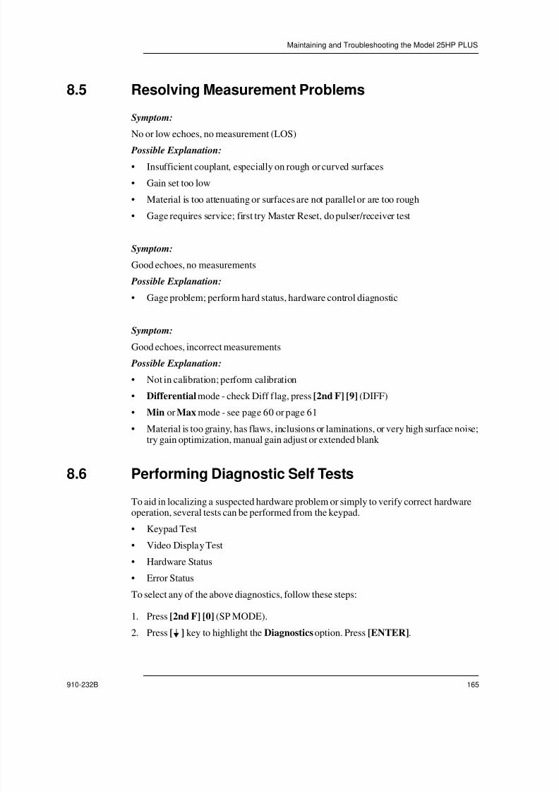
7/23/2019 Panametrics 25HP Plus Manual
http://slidepdf.com/reader/full/panametrics-25hp-plus-manual 165/230
Maintaining and Troubleshooting the Model 25HP PLUS
910-232B 165
8.5 Resolving Measurement Problems
Symptom:
No or low echoes, no measurement (LOS) Possible Explanation:
• Insufficient couplant, especially on rough or curved surfaces
• Gain set too low
• Material is too attenuating or surfaces are not parallel or are too rough
• Gage requires service; first try Master Reset, do pulser/receiver test
Symptom:
Good echoes, no measurements
Possible Explanation:
• Gage problem; perform hard status, hardware control diagnostic
Symptom:
Good echoes, incorrect measurements
Possible Explanation:
• Not in calibration; perform calibration
• Differential mode - check Diff flag, press [2nd F] [9] (DIFF)
• Min or Max mode - see page 60 or page 61• Material is too grainy, has flaws, inclusions or laminations, or very high surface noise;
try gain optimization, manual gain adjust or extended blank
8.6 Performing Diagnostic Self Tests
To aid in localizing a suspected hardware problem or simply to verify correct hardwareoperation, several tests can be performed from the keypad.
• Keypad Test
• Video Display Test
• Hardware Status
• Error Status
To select any of the above diagnostics, follow these steps:
1. Press [2nd F] [0] (SP MODE).
2. Press [ ] key to highlight the Diagnostics option. Press [ENTER].

7/23/2019 Panametrics 25HP Plus Manual
http://slidepdf.com/reader/full/panametrics-25hp-plus-manual 166/230
166 Model 25HP PLUS
3. Press [ ] or [ ] to highlight the Diagnostic you want to perform. Press [ENTER].
8.6.1 Performing a Keypad Test
To perform a Keypad Test, follow these steps:
1. Press [ ] or [ ] to select the Keypad option. Press [ENTER]. A replica of the keypadappears on the display.
2. Test any key by pressing it. If that specific key is working correctly, then the gagebeeps and that key is highlighted on the display.
Note: The [ON/OFF] key powers off the gage and the [ENTER] key exits theKeypad Test mode.
8.6.2 Performing a Video Display Test
To perform a Video Display Test, do the following:
Press [ ] or [ ] to select the Video option. Press [ENTER]. This test displays adarkened rectangle, which decreases in size.
If at any time a break appears in the pattern, then there is a problem with the waveformdisplay. Otherwise, the video display is operating normally.
8.6.3 Viewing the Hardware Status
To view the hardware status, do the following:
Press [ ] or [ ] to select Hardware Status and the following screen opens:

7/23/2019 Panametrics 25HP Plus Manual
http://slidepdf.com/reader/full/panametrics-25hp-plus-manual 167/230
Maintaining and Troubleshooting the Model 25HP PLUS
910-232B 167
The items shown on the screen above are:
SW Revision:
Displays revision of application and monitor software installed in gage.
SW Revision: Application/monitor Application: Main software that controls all gage operating functions.
Monitor (also known as Boot Loader): Controls gage's simplest I/O, display, keypad,and power management functions independent of the application. The primarypurpose is to load application software onto the gage.
V1: –V1:
Displays values of the power supply voltages V1 and –V1 measured when the gage ispowered on. Indicates whether voltages are within specification via a <Pass> or <Fail>message.
Specification: V1 = 5V ± 0.2 V V2 = -5V ± 0.2 V
DC Gain:
Displays measured value of the RF section's DC Gain at the Min, Mid, and Max dBsettings. This measurement approximates the full bandwidth gain (DC - 20 MHz). Testindicates whether all gains are within specification via a <Pass> or <Fail> message.Calibration performed when gage is powered on.
Specification: Min setting 17 to 21 dB
Mid setting 37 to 41 dB
Max setting 76 to 81 dB
Blank Cal, Detector Cal, Sampler Cal:
Displays measured values of hardware time delays in 70MHz clock counts. Test indicateswhether delays are within specification via a <Pass> or <Fail> message. Calibrationsperformed when gage is powered on.
Specification: Blank Cal: 64 to 96 counts (67 nominal)
Detector Cal: 70 nominal
Sampler Cal: 70 nominal
Threshold Cal, Offset1 Cal, Offset2 Cal, Flash ADC Cal:
Displays values of DAC settings used to center the RF input signal at the midpoint of theanalog-to-digital converter's input range (+2VDC). Values apply across full 80 dB gainrange. Calibration performed when gage is powered on.
Specification: DACs attempt to compensate for DC offset at 0, 40 and 80 dB. A<Fail> condition occurs after four attempts if error > 1 count of the analog-to-digitalconverter (~ 7.8 mV).
Battery:
Displays value of the battery voltage measured when gage is turned on and charger is notconnected. A <Pass> or <Fail> message is not included because the gage will not poweron during the <Fail> condition.

7/23/2019 Panametrics 25HP Plus Manual
http://slidepdf.com/reader/full/panametrics-25hp-plus-manual 168/230
168 Model 25HP PLUS
Specification: Battery = approximately 5.8V to 8V
RAM BANKs 1, 2, and 3:
Displays which of the 1.024 M Byte RAM Banks are installed.
8.6.4 Viewing the Error Status
To view the Error Status, do the following:
Press [2nd F] [0] (SP Mode) to select the Error Status option. This displays an errorlog.
8.7 Getting Help
Application, sales or problem solving assistance is available directly from Panametrics-NDTTM Customer Service. Call (800) 225-8330.
Panametrics-NDT will repair any Model 25HP PLUS gage at its Waltham,Massachusetts, USA factory. In addition, some local Panametrics-NDT dealers andagents are able to do repairs at customer sites or at their own facilities.
Replacement parts and accessories for the Model 25HP PLUS are available fromPanametrics-NDT.See Appendix F - Accessories and Replacement Parts on page 221.

7/23/2019 Panametrics 25HP Plus Manual
http://slidepdf.com/reader/full/panametrics-25hp-plus-manual 169/230
Appendix A - Technical Specifications
910-232B 169
Appendix A - Technical Specifications
Packaging
Case Material High impact Lexan.
Size 9.375 H x 5.45 W x 1.5 T inch.238 H x 138 W x 38 T mm.
Weight 2.1 lbs.
Connectors Transducer: Two size “0” small lemo. Allenvironmentally sealed RS-232: Sealed 6-pinLemo style.Charger: Sealed 4-pin Lemo style
Hand Strap Soft leather with adjustable velcro closure.
Temperature Operating: -5° F TO 112° F (-10° C to +50° C)
Case Splash proof.
Power
Battery Internal rechargeable NiCad battery pack. Rated at6V @ 1800 mAHr or Disposable Alkaline 6 “AA”cell.
Operating Time Per
Charge
25 hours minimum in Mode 1 at 4Hz with
backlight off.
Charger External wall plug-in charger for UniversalSupply (100VAC, 115VAC, and 230VAC) input.Charge time 2 Hours.
Keyboard Sealed and embossed membrane surface.Tactile and audible feedback.Color coded graphics.30 keys of 5 rows and 6 columns.

7/23/2019 Panametrics 25HP Plus Manual
http://slidepdf.com/reader/full/panametrics-25hp-plus-manual 170/230
170 Model 25HP PLUS
Display
Physical Graphics super twisted nematic liquid crystaldisplay.
Module Size: 114mm (W) x 100mm (H) x 14mm(T).
Viewing area: 102mm (W) x 86mm (H).
Dots: 240 (W) x 200 (H).
Dot Size: 0.36mm x 0.36mm.
Color: Dark blue image on naturalbackground.
Backlight Electroluminescent backlight for viewing in lowambient light condition. User selectable on or off.
InformationDisplayed
A-Scan echo waveform with graticule ofamplitude vs. thickness axis.
Waveform area: 200 (W) x94(H) dots.
Waveform Status Flags:F: FrozenH: HeldZ: ZoomedM: from datalogger memory
File name, ID number, stored value, and setupstored at ID numbers.
Stored data flags.

7/23/2019 Panametrics 25HP Plus Manual
http://slidepdf.com/reader/full/panametrics-25hp-plus-manual 171/230
Appendix A - Technical Specifications
910-232B 171
MeasurementLOS
Box 1: Normal M L
Box 2: D Differential Mode
d Percentage Differential
A Alarm Mode (Standard Alarm)
H High Alarm (Standard Alarm)
L Low Alarm (Standard Alarm)
p Alarm mode (Percent Previous Mode)
r Reduction Alarm (Percent Previous Mode)
g Growth Alarm (Percent Previous Mode)
P Alarm Mode (Absolute Previous Alarm Mode)
R Reduction Alarm (Absolute Previous Alarm Mode)
G Growth Alarm (Absolute Previous Alarm Mode)
Box 3: 1 Measure Mode 1
2 Measure Mode 2
3 Measure Mode 3
Box 4: M Maximum Value
m Minimum Value
Measurement values, Calibration values,Measurement flags
Measurement ValuesNumber of digits 5Digit height 0.425"
Measurement units and flags
IN or MM (Thickness)
IN/uSec or MM/uSec (Velocity)
Measurement ModeFlagUpdate Rate
MIN flag (Minimum mode)
MAX flag (Maximum mode)
Table 11 Information Displayed on the Model 25HP PLUS Screen

7/23/2019 Panametrics 25HP Plus Manual
http://slidepdf.com/reader/full/panametrics-25hp-plus-manual 172/230
172 Model 25HP PLUS
DIFF flag (Differential mode)
ALRM flag (Alarm mode)
CAL flag (Calibration mode)
CAL LOCK flag (Calibration Lock)
LOS flag (Loss Of Signal or Coupling)
Measurement
Performance Pitch and catch using Single, Delay, andImmersion.
Mode Mode 1: Time interval measurement fromthe main excitation pulse to the firstdetected echo.
Mode 2: Time interval measurement fromthe interface echo to the first backwall echo.
Mode 3: Time interval between multiplebackwall echoes.
Thickness
Range
The range of thickness capable of being
measured depends on the Setup selected, themeasured material, and the transducer typebeing used. Detailed ranges for eachstandard setup are specified in Table 13 onpage 179.In general, selection of the proper setup willallow thickness measurements over thefollowing ranges:
Steel: 0.006 to 20.000" 0.15 to508.00mm
Plastic: 0.003 to 2.000" 0.080 to50.80mm
MeasurementResolution
Selectable from the keypad LOW: 0.01" 0.1mmSTD: 0.001" 0.01mm
MeasurementLOS
Table 11 Information Displayed on the Model 25HP PLUS Screen (Continued)

7/23/2019 Panametrics 25HP Plus Manual
http://slidepdf.com/reader/full/panametrics-25hp-plus-manual 173/230
Appendix A - Technical Specifications
910-232B 173
MeasurementDisplay UpdateRate
Selectable from the keypad:4, 8, 12, 16, 20 measurements per second,averaging, or averaging with Quality Bar.Averaging is a running average of 5
measurements at the update rate.
MaterialVelocity Range
0.0200 in/ µsec to .66929 in/ µsec.0.5080 mm/ µsec to 17.0000 mm/ µsec.
MaterialVelocityResolution
.00001 in/ µsec or .0001 mm/ µsec.
Zero Cal Range 0.00 to 999.99 zero counts.
Differential Ref.Range
0.0 to 25.000" or 635.00mm.
Differential Ref.Resolution
Same as current gage resolution.
Alarm SetpointsRange
0.0 to 25.000" or 635.00mm.
Alarm SetpointsResolution
Same as current gage resolution.
Datalogger
InformationStored
• ID number
• Thickness value• Unit
• LOS/Measurement condition• Differential mode, DifferentialReference value
• Alarm mode, Low and Hi alarmreference values
• Minimum/Maximum reading• Velocity value• Transducer type• Waveform image (A-Scan, if selected)• Comments• Source: Downloaded or stored

7/23/2019 Panametrics 25HP Plus Manual
http://slidepdf.com/reader/full/panametrics-25hp-plus-manual 174/230
174 Model 25HP PLUS
StorageCapacity
Storage capacity of the gage depends on thefile type.Incremental or Sequential Files:18,000 measurements without waveforms
or 1,700 measurements with waveforms.Expandible: Memory Upgrade 1: 36,000 Thickness
3,400 Waveforms Memory Upgrade 2: 54,000Thickness
5,100 Waveforms
IdentificationNumber
Size: 1 to 16 charactersCharacter Set: 0 thru 9, A thru Z, * # : , / . -space
Data BaseStructure
DOS compatible file structure: File Name: 8 characters, DOS compatible. Number Of Files: Limited by availablememory.Size Of File: Limited by available memory.
File Creator(Matrix Maker)
IncrementalSequential (Defined by Starting and EndingID#)Sequential with custom points2-D Grid2-D Grid with custom points3-D Grid3-D Custom
File Utilities Open
CreateCopyDeleteSendEdit-RenameNote-CopyReports:File summary with StatisticsMin/Max SummaryFile comparisons

7/23/2019 Panametrics 25HP Plus Manual
http://slidepdf.com/reader/full/panametrics-25hp-plus-manual 175/230
Appendix A - Technical Specifications
910-232B 175
File OutputFormat
Ten selectable output formats: F1 - File Header, ID Header, ThicknessTable, Waveforms, Setup Table, and NoteTable
F2 - File Header, ID Header, ThicknessTable, Setup Table, and Note Table
F3 - ID Header, Thickness Table,Waveforms, Setup Table, Transducer SetupTable, and Note Table
F4 - Thickness Table
F5 - ID Header, Thickness Table, and
Setup Table
F6 - Thickness Table, Waveforms, SetupTable, Transducer Setup Table, and
Statistics F7 - 26DL PLUS format 16, ThicknessTable, Waveforms, Setup Table, and Note
Table
F8 - 26DL PLUS format 16 Character,Thickness Table, Setup, and Note Table
F9 -26DL PLUS format 12 Character, IDHeader, Thickness Table, Waveforms, andSetup Table
F10 - 26DL PLUS format 12 Character, IDHeader, Thickness Table, and Setup Table.
Features Erase any portion of the file or the entire file.Print reading and waveform (EPSONgraphics).Send reading in different format.Insert and/or append ID numbers.
Communication Protocol: Serial RS232 with +/-4Vsignal levels. Full duplex.
Baud: 1200, 2400, 4800, 9600,19200
Word Length: 8Stop Bits: 1 or 2
Parity: Even, Odd, or NoneAgencyApproval
CE.
Functions
Units The measurement units are keypadselectable as either inches or millimeters.

7/23/2019 Panametrics 25HP Plus Manual
http://slidepdf.com/reader/full/panametrics-25hp-plus-manual 176/230
176 Model 25HP PLUS
Resolution The measurement resolution is selectableamong standard and low resolution from thekeypad:Standard: .001" (.01mm)
Low: .01" (.1mm)
Velocity Standard: 0.0001in/ µsec (0.001mm/ µsec)Low: 0.001in/ µsec(0.01mm/ µsec)
Time of Flight 000.01µsec Fixed
Echo DetectionMethods
The following are selected as part of theApplication Setup.
Mode 1: Time between excitation pulse andfirst echo following blank period usingcontact transducers.
Mode 2: Time between the interface echoand the first backwall echo. Normally usedwith delay line or immersion transducers.
Mode 3: Time between a pair of backwallechoes following the interface echo.Normally used with delay line or immersiontransducers.
Min Mode Current thickness is displayed duringtransducer contact and the minimumthickness measured is displayed duringLOS.
Max Mode Current thickness is displayed duringtransducer contact and the maximumthickness measured is displayed duringLOS.
Hold/blank The thickness display during LOS may beset to either HOLD the last reading duringLOS or BLANK the display during LOS.
Differential The thickness display may be set to displayeither actual measured thickness or thedifference between the measured thickness
and a user-set “Differential ThicknessReference Value”. The default is a Diff. Ref.Value of 0.000 and Diff Measure modeOFF.

7/23/2019 Panametrics 25HP Plus Manual
http://slidepdf.com/reader/full/panametrics-25hp-plus-manual 177/230
Appendix A - Technical Specifications
910-232B 177
Calibration
View and/or set the material velocity by pressing [VEL] from the Measure
mode, or by selecting MatlVel from the Setup Parameter List.View and/or set the Zero Calibration by pressing [ZERO] from the Measure mode, or by selecting Zero from the Setup Parameter List.
Preform the Velocity and/or Zero Calibration by entering the known
thickness(es) of test block(s) while measuring the block(s).Application Setups
Application Setups are a set of stored configurations of the gage parameters for
various measurement applications. Setups are optimized for such applicationfeatures as material, thickness range, and required accuracy or resolution.When the gage is turned on, the last Setup used is automatically selected and
the gage is ready to make similar measurements.If the application has changed, choose an Application Setup name based on thenew application (refer to Table 12 on page 178).
Alarm The gage may be set to indicate visually andaudibly whenever the measured thickness isless than a user-set Low Alarm value orgreater than a user-set High Alarm
value.The default is Low Alarm value =0.000, High Alarm value = full scale, andAlarm Measure mode OFF.

7/23/2019 Panametrics 25HP Plus Manual
http://slidepdf.com/reader/full/panametrics-25hp-plus-manual 178/230
178 Model 25HP PLUS
Setup Name Probe Type Typical Application
DEFM1-0.5/M101 M101 Steel: 0.5 - 25" (12 - 635mm)
Plastic: 0.20" - 5.0" (5-12.5mm)
DEFTT-0.5/M101 M101 Steel: 0.250 - 25.0" (6.25 - 635mm)
DEFM1-1.0/M102 M102 Steel: 0.200 - 25" (5 - 635mm)
Plastic: 0.1" - 3.0" (2.5 - 75mm)
DEFM1-1.0/M103 M103 Steel: 0.1 - 25" (2.5 - 635mm)
Plastic: 0.100 - 3.0" (2.5-75mm)
DEFM1-2.25/M106 M106 Steel: 0.075 - 25" (2 -635mm)
Plastic: 0.050 - 3.0" (1.2-75mm)
DEFM1-5.0/M109 M109 Steel: 0.050 - 10" (1.2 - 250mm)
Plastic: 0.040 - 2.0" (1.0 - 50mm)
DEFM1-5.0/M110 M110 Steel: 0.050 -10.00" (1.2 - 250mm)
Plastic: 0.040 -1.0" (1.0-25mm)
DEFM2-2.25/M1036 M1036 Steel: 0.075 - 25" (2 - 635mm)
Plastic:0.050 - 3.0" (1.2 - 75mm)
DEFP2-5.0/M201 M201 Plastic: 0.050 - 0.400" (1.2 - 10mm)
DEFM2-5.0/M201 M201 Steel: 0.050 - 1.0" (1.2 - 10mm)
DEFP2-5.0/M206 M206 Plastic: 0.040 - 0.5" (1.0 - 25mm)
DEFM2-5.0/M206 M206 Steel: 0.050 - 1.0" (1.2 - 12mm)
DEFP2-2.25/M207 M207 Plastic: 0.075 - 0.5" (2.0 - 12mm)
DEFM2-2.25/M207 M207 Steel: 0.075 - 1.0" (2 - 25mm)
Table 12 Setup Name and Application

7/23/2019 Panametrics 25HP Plus Manual
http://slidepdf.com/reader/full/panametrics-25hp-plus-manual 179/230
Appendix A - Technical Specifications
910-232B 179
DEFP1-0.5/M2008 M2008 Smooth Fiberglass: 0.2 - 3.0" (5.0 -75mm)
DEFM1-2.25/V154 V154 Steel: 0.150 - 3.0" (3.75 - 75mm)
DEF1-5.0/V156 V156 Steel 0.050 - 0.75" (1.25 - 19mm)
DEFM1-1.0/V153 V153 Steel 0.500 - 10.00" (12 - 400mm)
DEFM2-0.5/V301 V301 Steel: 0.250 - 5.0" (6 - 127mm
DEFP2-0.5/V301 V301 Plastic: 0.200 - 3.00" (5 - 75mm)
DEFM2-1.0 /V303 V303 Steel: 0.200 - 2.00" (5 - 50mm)
DEFP2-1.0/V303 V303 Plastic: 0.150 - 1.00" (3.75 - 25mm)
DEFM2-2.25/V306 M306 Steel: 0.300 - 1.00" (5 - 25mm)
DEFP2-2.25/V306 M306 Plastic 0.100 - 0.500" (2.5 - 12mm)
Setup Quantity 35 factory default setups. Space for 25 custom definedsetups.
Custom Application Setups Applications that are not covered by any of the defaultsetups can be measured by creating a custom setup for
the special application. This setup may be done byadjusting the parameters of the closest default setup.
A description of the setup parameters, which can beadjusted to make a custom setup are listed in Table 13on page 179.
Name Description Units/Resolutions/Range
Mode Echo Detect Mode 1, 2 or 3.
Setup Name User defined Setup Name 16characters MAX.
ProbeType Transducer type One of the 11 Panametrics-NDTTM transducer types from defaultsetup list.
PulserPwr Pulser power 30, 60, or 110 Volts.
Table 13 Setup Parameter Description
Table 12 Setup Name and Application (Continued)

7/23/2019 Panametrics 25HP Plus Manual
http://slidepdf.com/reader/full/panametrics-25hp-plus-manual 180/230
180 Model 25HP PLUS
MaxGain Maximum receiver gain 0 - 79.6dB, 1dB steps.
InitGain Initial TVD gain 0 - MaxGain, 1dB steps.
TDGSlope Time Gain slope (default 0 - 26.5dB/s, 0.1dB/s steps.
MBBlank Main Bang Blank 55ns to 200s, 0.14s steps. 22ns orEcho Window time interval,whichever is less.
EchWindow Echo window. Echo detectgate which begins at end ofMB Blank in Mode 1 OrInterface Echo In Modes 2 &3. The value reported for theend of Echo Window is
relative to the Main Bang.
55ns to 200s, .014 s steps. 55ns orMB Blank time interval,whichever is less.
P/R Config Configuration of the PulserReceiver Mode.
Pulse Echo, Thru Transmission orPitch Catch.
Echo1Detect Detection polarity of firstecho
+ or -
Echo2Detect Detection polarity of secondecho
+ or -
IFBLANK Blank after Interface echo 0 -20000 ns, 14 ns steps.
M3Blnk Blank after first measuredbackwall echo in Mode 3
0 - 20000 ns, 14 ns steps.
MatlVel Ultrasonic sound velocity ofmaterial to be measured
.02000 - .66929"/s (0.5080 -17.0000mm/s).
Zero Zero calibration factor 0 -999.99.
Name Description Units/Resolutions/Range
Table 13 Setup Parameter Description (Continued)

7/23/2019 Panametrics 25HP Plus Manual
http://slidepdf.com/reader/full/panametrics-25hp-plus-manual 181/230
Appendix A - Technical Specifications
910-232B 181
General
Battery and Charger
Display Dot matrix, graphics, Super Twisted Nematic, monochrome,
transflective, liquid crystal display.
Viewable area is 2.22". x 1.51" (56.28mm x 38.36mm).Electroluminescent backlight. Contrast is adjustable from thekeypad.
Keypad Sealed and embossed membrane surface. Tactile and audiblefeedback color-coded graphics 30 keys.
Transducers Can be used with contact, delay line, and immersiontransducers from 0.500MHz to 5.0MHz.
Physical Size: 9.375" x 5.45" x 1.5(238mm x 138mm x 38mm)
Weight: 2.1 lb. (0.951 kg)Case: Material is LexanConstruction: Dust and splash proof
Operating Temperature: 0oC to 50°C
Battery Description 6V Rechargeable NiCad pack or field-replaceable alkalineAA batteries.
Battery Run Time 25 hours typical in Mode 1with 4Hz update rate andbacklight turned off.
Battery Charge Time 2 hours (using 36CAPLUS).
Charger 36CAPLUS charger/AC adapter unit (will not rechargealkaline batteries).
Optional Operation with six disposable alkaline “AA” cell isavailable as a factory installed option. 70 hours typical runtime.

7/23/2019 Panametrics 25HP Plus Manual
http://slidepdf.com/reader/full/panametrics-25hp-plus-manual 182/230
182 Model 25HP PLUS
Special Gage Functions
General Access many gage functions, which do not require frequent
changing, by using the Special or SP keypad mode.Access all these features by pressing [2ND F], [IN/MM] (SP
MODE). Press [ ], [ ], and [ENTER] to select a categoryof SP functions (Measurement, Communication,Diagnostic, Reset, Clock). Finally select a particular
function to modify by pressing [ ], [ ], [ ], [ ], and[ENTER].
List Of SpecialFunctions
Measurement:Beeper (on* or off)Inactive time (on* or off)Language (English*, Spanish, German, French)
Radix (period* or comma)Waveform (unfill* or fill)Backlight mode (normal* or auto)Supv lock (off* or on)Save key (thk* or thk & wf)P/R config (pulse echo*, thru transmission, pitch catch)ID overwrite (off* or on)Quick setup (off* or on)* indicates the parameter default
Communication:Baud (192000*, 9600, 4800, 2400, 1200)Stop bits (1* or 2)
Parity (none*, odd, or even)Comm protocol (multiple* or single)Output format (F1*, F2, F3, F4, F5)* indicates the parameter default
Diagnostic:KeypadVideoHardware statusHardware controlError status

7/23/2019 Panametrics 25HP Plus Manual
http://slidepdf.com/reader/full/panametrics-25hp-plus-manual 183/230
Appendix A - Technical Specifications
910-232B 183
RESETSMeasure Reset: (default values)Std. resolution4Hz Measure rate
Diff. value 0.000Diff mode OFFDisplay blank Inactive time onAlarm off Low alarm 0.000High alarm 20.000Min off Max off Backlight off
Communication Reset: (default values)Baud: 19200
Stop bit: 1Parity: noneComm protocol: multipleOutput format: F1
Dbase Reset:This reset function clears the entire data base. UseCAUTION: this function will erase all stored data, whichcannot be recalled.
Master Reset:Performs all Measurement, Communications and Dbaseresets simultaneously.

7/23/2019 Panametrics 25HP Plus Manual
http://slidepdf.com/reader/full/panametrics-25hp-plus-manual 184/230
184 Model 25HP PLUS
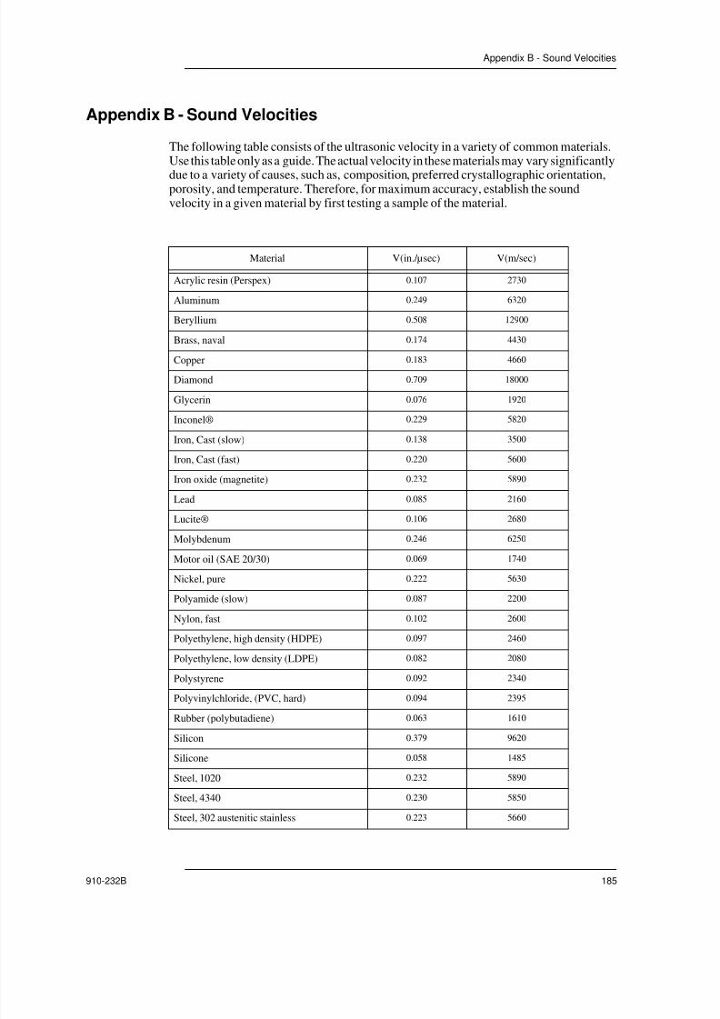
7/23/2019 Panametrics 25HP Plus Manual
http://slidepdf.com/reader/full/panametrics-25hp-plus-manual 185/230
Appendix B - Sound Velocities
910-232B 185
Appendix B - Sound Velocities
The following table consists of the ultrasonic velocity in a variety of common materials.Use this table only as a guide. The actual velocity in these materials may vary significantly
due to a variety of causes, such as, composition, preferred crystallographic orientation,porosity, and temperature. Therefore, for maximum accuracy, establish the soundvelocity in a given material by first testing a sample of the material.
Material V(in./µsec) V(m/sec)
Acrylic resin (Perspex) 0.107 2730
Aluminum 0.249 6320
Beryllium 0.508 12900
Brass, naval 0.174 4430
Copper 0.183 4660
Diamond 0.709 18000
Glycerin 0.076 1920
Inconel® 0.229 5820
Iron, Cast (slow) 0.138 3500
Iron, Cast (fast) 0.220 5600
Iron oxide (magnetite) 0.232 5890
Lead 0.085 2160
Lucite® 0.106 2680
Molybdenum 0.246 6250
Motor oil (SAE 20/30) 0.069 1740
Nickel, pure 0.222 5630
Polyamide (slow) 0.087 2200
Nylon, fast 0.102 2600
Polyethylene, high density (HDPE) 0.097 2460
Polyethylene, low density (LDPE) 0.082 2080
Polystyrene 0.092 2340
Polyvinylchloride, (PVC, hard) 0.094 2395
Rubber (polybutadiene) 0.063 1610
Silicon 0.379 9620
Silicone 0.058 1485
Steel, 1020 0.232 5890
Steel, 4340 0.230 5850
Steel, 302 austenitic stainless 0.223 5660

7/23/2019 Panametrics 25HP Plus Manual
http://slidepdf.com/reader/full/panametrics-25hp-plus-manual 186/230
186 Model 25HP PLUS
References
Folds, D. L. “Experimental Determination of Ultrasonic Wave Velocities in Plastics,Elastomers, and Syntactic Foam as a Function of Temperature,” Naval Research andDevelopment Laboratory, Panama City, Florida, 1971.
Fredericks, J. R. Ultrasonic Engineering, John Wiley & Sons, Inc., New York, 1965.
“Handbook of Chemistry and Physics” Chemical Rubber Co., Cleveland, Ohio, 1963.
Mason, W. P. Physical Acoustics and the Properties of Solids, D.Van Nostrand Co., NewYork, 1958.
Papadakis, E. P. Panametrics - unpublished notes, 1972.
Steel, 347 austenitic stainless 0.226 5740
Tin 0.131 3320
Titanium, Ti 150A 0.240 6100
Tungsten 0.204 5180
Water (20°C) 0.0580 1480
Zinc 0.164 4170
Zirconium 0.183 4650
Material V(in./µsec) V(m/sec)

7/23/2019 Panametrics 25HP Plus Manual
http://slidepdf.com/reader/full/panametrics-25hp-plus-manual 187/230
Appendix C - Serial Interface
910-232B 187
Appendix C - Serial Interface
Mechanical Description
The Input-Output (I/O) connector, a 6 position circular LEMO style receptacle, is located
in the center of the top of the Model 25HP PLUS. The mating connector inserts into theI/O connector with the red dot upward and pushed straight in until it snaps into place. Towithdraw, pull the collet to release the latch and pull straight out.
Panametrics-NDTTM provides cables to connect the Model 25HP PLUS to devices withstandard DB-25 male and female connectors and also the IBM PC-AT 9 male pin serial I/ O connector. Use the information in Table 15 on page 187 as a reference to verifyparticular equipment compatibility with the Model 25HP PLUS, and as an aid inconstructing a custom cable if necessary.
Model 25HPPLUS I/OConnector
Wire Name Signal NameIBM PC-AT
Connector
STD DB25
Pin #
1 Foil/tinnedcopper
Ground 5 7
2 Red Data from Gage 2 3
3 Orange Data to Gage 3 2
4 Yellow Do not connect – –
5 Green DTR from Gage 6 6
6 Blue DSR to Gage 4 20
Table 15 Equipment Compatibility
Panametrics-NDTTM
Length(Feet)
Length(Meters)
Cable ConnectorStock No. Part No.
704-689-01 36DLC/9F-6 6 2 IBM PC-AT (9 Pin Female)
704-690-01 36DLC/25M-6 6 2 25 Pin Male “D”
704-691-01 36DLC/25F-6 6 2 25 Pin Female “D” (PC/XT)
704-689-02 36DLC/9F-12 12 4 IBM PC-AT (9 Pin Female)
704-690-02 36DLC/25M-12
12 4 25 Pin Male “D”
704-691-02 36DLC/25F-12
12 4 25 Pin Female “D” (PC/XT)
Table 16 Standard 36DL PLUS I/O Cables

7/23/2019 Panametrics 25HP Plus Manual
http://slidepdf.com/reader/full/panametrics-25hp-plus-manual 188/230
188 Model 25HP PLUS
Note: Custom cables with a user specified terminal connector may be ordered fromPanametrics-NDTTM.
Electrical Definition and Data Format
Data is transmitted on one line (data out of gage) and received on another line (data intogage). Transfer is asynchronous serial. Baud rate, word length, stop bits and parity areselectable from the keyboard. Data consists of ASCII coded character strings.
Signal levels are RS-232 C/D compatible. Mark is less than -2.5 volts. Space is greaterthan +2.5V. The maximum output signal range is ±5.50 volts. The maximum input signalrange is ± 20 volts.
The following two hardware handshake lines are included:
DTR: The gage sets DTR low (<-2.5V) when it is not able to receive data. DTR is high(>+2.5V) at all times.
DSR: A high (>+2.5V) supplied by the external device (or by being connected to theDTR line) enables the gage to transmit data. A low (<-2.5V) supplied by theexternal device, or by being connected to the RTS line, prevents the gage fromtransmitting data.
Note: If the external device does not provide the proper DSR signal, then you mustconnect DTR to DSR (jump pin 6 to pin 20 in the 25 position cableconnector), or in the 25 pin connector on the attached equipment.
704-718-06 36DLC/9M/ PR-6
6 2 9 Pin Male “D” (PortablePrinter)
Panametrics-NDTTM
Length(Feet)
Length(Meters)
Cable ConnectorStock No. Part No.
Table 16 Standard 36DL PLUS I/O Cables (Continued)

7/23/2019 Panametrics 25HP Plus Manual
http://slidepdf.com/reader/full/panametrics-25hp-plus-manual 189/230
Appendix D - Data Output Format
910-232B 189
Appendix D - Data Output Format
There are 10 data formats that the Model 25HP PLUS is capable of sending. F-1 to F-6 areModel 25HP PLUS series formats, while F-7 to F-10 are Model 26DL PLUS compatible
formats. The Model 25HP PLUS also has File Transfer Protocol (FTP) to transfer filesback and forth between the gage and the PC. See Appendix E - Remote Control Via RS-232 on page 213 for more information about FTP.
FormatFileHeader
IDHeader
ThicknessTable
Wave-forms
SetupTable
AppsetupTable
StatisticsNoteTable
F-1 X X X X X X
F-2 X X X X X
F-3 X X X X X X
F-4 X
F-5 X X X
F-6 X X X X X
F-7 X X X X
F-8 X X X
F-9 X X X X
F-10 X X X
Table 17 Model 25HP PLUS Output Formats

7/23/2019 Panametrics 25HP Plus Manual
http://slidepdf.com/reader/full/panametrics-25hp-plus-manual 190/230
190 Model 25HP PLUS
FORMAT – F1This format includes file header, 25HP PLUS thickness table with waveforms (whenever present),setup table and note table.
0 1 2 3 4 5 6
0123456789012345678901234567890123456789012345678901234567890123456789
FILE NAME: A0000001
FILE TYPE: INCREMENTAL
FILE DESCRIPTION: DEMO OUTPUT FORMAT
INSPECTOR ID: PANAMETRICS TESTER 9999999999999
LOCATION NOTE: WALTHAM MA 02453 USA
FILE DELETE PROTECTION: ON
OK
IDENTIFIER THICKNESS UNITS FLAGS NOTES SU #
0000000001 0.277 IN M--1WF AB 0002
PIXEL AMPLITUDES
00 28 00 00 00 00 00 00 00 00 00 00 00 00 00 00 00 00 00 00
00 00 00 00 00 00 00 21 21 49 49 5A 5A 5A 5A 6B 6B 74 74 77
77 77 77 7B 7B 7D 7D 7E 7E 7E 7E 7F 7F 80 80 81 81 81 81 81
81 81 81 82 82 82 82 82 81 82 81 81 81 82 82 82 82 82 82 82
82 82 82 82 82 82 82 83 82 83 82 82 82 82 82 82 82 82 82 82
82 82 82 82 82 82 82 82 82 83 83 83 83 83 83 83 83 83 83 83
82 83 82 82 82 83 82 83 82 82 82 82 82 83 82 83 82 82 82 82
82 83 83 83 83 83 82 83 82 84 83 84 83 83 83 83 83 83 82 83
82 83 83 83 82 83 82 83 83 83 83 83 83 83 83 83 83 83 83 83
83 83 83 83 83 83 83 83 83 83 83 83 83 83 83 83 83 83 83 83 83 83 83 83 83 83 83 83 83 83 83 83 83 83 83 83 83 83 83 83
83 83 83 83 83 83 83 83 83 84 83 84 83 83 83 83 83 84 84 96
96 96 96 B0 80 B0 3C 80 3C 3C 3C 4F 4F 7B 7B 8E 8E 9D 9D 9D
9D 9E 93 9E 8A 93 8A 8A 82 8A 7D 82 7D 7D 7D 7D 7D 7F 7F 80
80 81 81 82 82 82 82 82 82 83 83 83 83 83 83 83 83 83 83 83
83 83 83 84 83 84 83 83 83 83 83 83 83 83 83 83 83 83 83 83
83 83 83 83 82 83 82 83 83 83 83 83 83 83 82 83 82 82 82 83
81 83 81 81 81 81 81 81 81 81 81 83 83 83 83 83 83 85 85 85
85 85 85 85 85 85 85 85 83 85 83 83 83 83 82 83 82 82 82 82
82 82 82 82 82 83 83 83 83 83 83 83 83 83 83 83 83 83 83 84
ZOOM = FALSE
DELAY = 0.00RANGE = 0.50
DETECTION MARKER1 = 132
DETECTION MARKER2 = 0
MAIN BANG BLANK END = 31
ECHO WINDOW END = 207
INTERFACE BLANK START = 0
INTERFACE BLANK END = 0

7/23/2019 Panametrics 25HP Plus Manual
http://slidepdf.com/reader/full/panametrics-25hp-plus-manual 191/230
Appendix D - Data Output Format
910-232B 191
MODE3 BLANK START = 0
MODE3 BLANK END = 0 RECTIFICATION = RF
0000000002 0.374 IN M--1WF CD 0002
PIXEL AMPLITUDES
00 27 00 00 00 00 00 00 00 00 00 00 00 00 00 00 00 00 00 00
00 00 00 00 00 00 00 10 10 3E 3E 52 52 52 52 66 66 72 72 75
75 75 75 7A 7A 7C 7C 7D 7D 7D 7D 7E 7E 80 80 81 81 82 82 82
82 82 82 82 82 82 82 82 81 82 81 82 82 82 82 82 82 82 82 82
82 82 82 82 82 82 82 83 82 83 82 82 82 82 82 82 82 82 82 82
82 82 82 82 82 82 82 82 82 83 83 83 82 83 82 82 82 82 82 82
82 82 82 82 82 82 82 83 83 83 82 83 82 82 82 83 83 83 83 83
83 83 82 83 82 82 82 83 83 83 82 83 82 82 82 82 82 83 82 83
82 83 83 83 82 83 82 83 83 83 83 83 82 83 82 82 82 82 82 83
83 83 82 83 82 83 82 83 82 82 82 82 82 83 82 83 82 82 82 83
83 83 83 83 82 83 82 82 82 82 82 83 82 83 82 82 82 82 82 82
82 83 83 83 82 83 82 84 83 84 83 83 83 83 83 83 83 83 83 83
83 83 82 83 82 83 83 83 83 83 82 83 82 83 83 83 83 83 83 83
83 83 83 83 83 83 83 83 83 83 83 83 83 83 83 83 83 83 83 83
83 83 83 83 83 83 83 83 83 83 83 84 84 84 82 84 82 82 82 82
82 82 82 83 83 83 83 83 83 83 83 83 83 83 83 84 84 93 93 93
93 AD 83 AD 3E 83 3E 4A 4A 4A 4A 7B 7B 94 94 A3 A3 A3 A1 A3
93 A1 86 93 86 86 7D 86 7B 7D 7B 7C 7C 7F 7F 7F 7F 80 80 81
81 82 82 82 82 83 83 83 83 83 83 83 83 84 82 84 82 84 83 84
83 83 83 83 82 83 82 82 82 82 82 82 82 83 83 83 83 83 83 83
ZOOM = FALSE
DELAY = 0.00
RANGE = 0.50
DETECTION MARKER1 = 170
DETECTION MARKER2 = 0
MAIN BANG BLANK END = 31
ECHO WINDOW END = 207
INTERFACE BLANK START = 0
INTERFACE BLANK END = 0
MODE3 BLANK START = 0
MODE3 BLANK END = 0 RECTIFICATION = RF
0000000003 0.475 IN M--1WF 0002
PIXEL AMPLITUDES
00 28 00 00 00 00 00 00 00 00 00 00 00 00 00 40 40 56 56 71
71 76 76 7B 7B 7E 7E 80 80 81 81 82 82 82 81 82 81 82 82 82
82 82 81 82 81 82 82 82 82 82 81 82 81 82 82 82 82 82 82 83
FORMAT – F1 (Continued)This format includes file header, 25HP PLUS thickness table with waveforms (whenever present),setup table and note table.

7/23/2019 Panametrics 25HP Plus Manual
http://slidepdf.com/reader/full/panametrics-25hp-plus-manual 192/230
192 Model 25HP PLUS
82 82 82 83 83 83 83 83 83 83 82 83 82 83 81 83 83 84 83 83
82 83 82 83 82 83 82 83 83 83 83 83 82 83 83 83 83 83 83 83 83 83 83 83 83 83 83 83 83 83 83 83 82 83 82 83 82 83 83 83
83 83 83 84 83 83 83 83 83 84 83 84 83 83 83 83 83 83 83 83
83 83 83 83 83 83 83 83 83 83 83 83 83 83 83 83 82 83 82 83
83 83 83 83 83 83 83 83 83 83 83 83 83 83 83 83 83 83 83 83
82 83 83 83 82 84 82 83 83 84 83 83 83 83 83 83 83 90 90 AB
46 AB 40 72 72 91 91 A2 96 A2 82 96 7D 82 7C 7D 7D 80 80 82
82 83 83 84 84 84 84 84 83 84 83 83 83 83 83 83 83 83 83 83
83 84 84 84 83 84 83 83 83 83 83 84 83 84 83 83 83 83 83 83
83 83 83 83 83 83 83 83 83 83 82 84 82 83 83 83 83 84 83 84
82 83 81 82 81 84 84 85 85 86 84 86 82 84 82 82 82 82 82 83
83 83 83 83 83 84 83 84 83 84 83 84 83 83 83 83 83 83 83 84
83 84 83 84 82 83 82 83 83 83 83 83 83 84 84 84 83 84 83 83
83 83 83 83 83 83 83 83 83 83 83 83 83 83 83 83 83 83 83 84
83 84 83 84 84 85 83 85 83 83 82 83 82 82 82 83 83 83 83 83
82 84 82 83 83 83 83 83 83 84 84 84 84 90 8C 90 67 8C 67 89
ZOOM = FALSE
DELAY = 0.00
RANGE = 1.00
DETECTION MARKER1 = 109
DETECTION MARKER2 = 0
MAIN BANG BLANK END = 19
ECHO WINDOW END = 207
INTERFACE BLANK START = 0
INTERFACE BLANK END = 0
MODE3 BLANK START = 0
MODE3 BLANK END = 0
RECTIFICATION = RF
OK
SU # VEL(/uS) DIFF LO-ALM HI-ALM UNITS MEAS-TYPE REF-THK
0002 0.22600 0.000 0.000 25.000 IN THK 0.500
OK
CODE COMMENT A 001
B 002
C 003
D 004
OK
FORMAT – F1 (Continued)This format includes file header, 25HP PLUS thickness table with waveforms (whenever present),setup table and note table.

7/23/2019 Panametrics 25HP Plus Manual
http://slidepdf.com/reader/full/panametrics-25hp-plus-manual 193/230
Appendix D - Data Output Format
910-232B 193
FORMAT – F2This format includes file header, 25HP PLUS thickness table, setup table and note table andexcludes waveform.
0 1 2 3 4 5 6
0123456789012345678901234567890123456789012345678901234567890123456789
FILE NAME: A0000001
FILE TYPE: INCREMENTAL
FILE DESCRIPTION: DEMO OUTPUT FORMAT
INSPECTOR ID: PANAMETRICS TESTER 9999999999999
LOCATION NOTE: WALTHAM MA 02453 USA
FILE DELETE PROTECTION: ON
OK
IDENTIFIER THICKNESS UNITS FLAGS NOTES SU # 0000000001 0.277 IN M--1WF AB 0002
0000000002 0.374 IN M--1WF CD 0002
0000000003 0.475 IN M--1WF 0002
OK
SU # VEL(/uS) DIFF LO-ALM HI-ALM UNITS MEAS-TYPE REF-THK
0002 0.22600 0.000 0.000 25.000 IN THK 0.500
OK
CODE COMMENT A 001
B 002
C 003
D 004
OK

7/23/2019 Panametrics 25HP Plus Manual
http://slidepdf.com/reader/full/panametrics-25hp-plus-manual 194/230
194 Model 25HP PLUS
FORMAT – F3This format includes 25HP PLUS thickness table with waveforms (whenever present) setup table,application setup table and note table and excludes fileheader.
0 1 2 3 4 5 6
0123456789012345678901234567890123456789012345678901234567890123456789
IDENTIFIER THICKNESS UNITS FLAGS NOTES SU #
0000000001 0.277 IN M--1WF AB 0002
PIXEL AMPLITUDES
00 28 00 00 00 00 00 00 00 00 00 00 00 00 00 00 00 00 00 00
00 00 00 00 00 00 00 21 21 49 49 5A 5A 5A 5A 6B 6B 74 74 77
77 77 77 7B 7B 7D 7D 7E 7E 7E 7E 7F 7F 80 80 81 81 81 81 81
81 81 81 82 82 82 82 82 81 82 81 81 81 82 82 82 82 82 82 82
82 82 82 82 82 82 82 83 82 83 82 82 82 82 82 82 82 82 82 82
82 82 82 82 82 82 82 82 82 83 83 83 83 83 83 83 83 83 83 83
82 83 82 82 82 83 82 83 82 82 82 82 82 83 82 83 82 82 82 82
82 83 83 83 83 83 82 83 82 84 83 84 83 83 83 83 83 83 82 83
82 83 83 83 82 83 82 83 83 83 83 83 83 83 83 83 83 83 83 83
83 83 83 83 83 83 83 83 83 83 83 83 83 83 83 83 83 83 83 83
83 83 83 83 83 83 83 83 83 83 83 83 83 83 83 83 83 83 83 83
83 83 83 83 83 83 83 83 83 84 83 84 83 83 83 83 83 84 84 96
96 96 96 B0 80 B0 3C 80 3C 3C 3C 4F 4F 7B 7B 8E 8E 9D 9D 9D
9D 9E 93 9E 8A 93 8A 8A 82 8A 7D 82 7D 7D 7D 7D 7D 7F 7F 80 80 81 81 82 82 82 82 82 82 83 83 83 83 83 83 83 83 83 83 83
83 83 83 84 83 84 83 83 83 83 83 83 83 83 83 83 83 83 83 83
83 83 83 83 82 83 82 83 83 83 83 83 83 83 82 83 82 82 82 83
81 83 81 81 81 81 81 81 81 81 81 83 83 83 83 83 83 85 85 85
85 85 85 85 85 85 85 85 83 85 83 83 83 83 82 83 82 82 82 82
82 82 82 82 82 83 83 83 83 83 83 83 83 83 83 83 83 83 83 84
ZOOM = FALSE
DELAY = 0.00
RANGE = 0.50
DETECTION MARKER1 = 132 DETECTION MARKER2 = 0
MAIN BANG BLANK END = 31
ECHO WINDOW END = 207
INTERFACE BLANK START = 0
INTERFACE BLANK END = 0
MODE3 BLANK START = 0

7/23/2019 Panametrics 25HP Plus Manual
http://slidepdf.com/reader/full/panametrics-25hp-plus-manual 195/230
Appendix D - Data Output Format
910-232B 195
MODE3 BLANK END = 0
RECTIFICATION = RF
0000000002 0.374 IN M--1WF CD 0002
PIXEL AMPLITUDES
00 27 00 00 00 00 00 00 00 00 00 00 00 00 00 00 00 00 00 00
00 00 00 00 00 00 00 10 10 3E 3E 52 52 52 52 66 66 72 72 75
75 75 75 7A 7A 7C 7C 7D 7D 7D 7D 7E 7E 80 80 81 81 82 82 82
82 82 82 82 82 82 82 82 81 82 81 82 82 82 82 82 82 82 82 82
82 82 82 82 82 82 82 83 82 83 82 82 82 82 82 82 82 82 82 82
82 82 82 82 82 82 82 82 82 83 83 83 82 83 82 82 82 82 82 82
82 82 82 82 82 82 82 83 83 83 82 83 82 82 82 83 83 83 83 83 83 83 82 83 82 82 82 83 83 83 82 83 82 82 82 82 82 83 82 83
82 83 83 83 82 83 82 83 83 83 83 83 82 83 82 82 82 82 82 83
83 83 82 83 82 83 82 83 82 82 82 82 82 83 82 83 82 82 82 83
83 83 83 83 82 83 82 82 82 82 82 83 82 83 82 82 82 82 82 82
82 83 83 83 82 83 82 84 83 84 83 83 83 83 83 83 83 83 83 83
83 83 82 83 82 83 83 83 83 83 82 83 82 83 83 83 83 83 83 83
83 83 83 83 83 83 83 83 83 83 83 83 83 83 83 83 83 83 83 83
83 83 83 83 83 83 83 83 83 83 83 84 84 84 82 84 82 82 82 82
82 82 82 83 83 83 83 83 83 83 83 83 83 83 83 84 84 93 93 93
93 AD 83 AD 3E 83 3E 4A 4A 4A 4A 7B 7B 94 94 A3 A3 A3 A1 A3 93 A1 86 93 86 86 7D 86 7B 7D 7B 7C 7C 7F 7F 7F 7F 80 80 81
81 82 82 82 82 83 83 83 83 83 83 83 83 84 82 84 82 84 83 84
83 83 83 83 82 83 82 82 82 82 82 82 82 83 83 83 83 83 83 83
ZOOM = FALSE
DELAY = 0.00
RANGE = 0.50
DETECTION MARKER1 = 170
DETECTION MARKER2 = 0
MAIN BANG BLANK END = 31
ECHO WINDOW END = 207
INTERFACE BLANK START = 0
INTERFACE BLANK END = 0
MODE3 BLANK START = 0
MODE3 BLANK END = 0
RECTIFICATION = RF
FORMAT – F3 (Continued)This format includes 25HP PLUS thickness table with waveforms (whenever present) setup table,application setup table and note table and excludes fileheader.

7/23/2019 Panametrics 25HP Plus Manual
http://slidepdf.com/reader/full/panametrics-25hp-plus-manual 196/230
196 Model 25HP PLUS
0000000003 0.475 IN M--1WF 0002
PIXEL AMPLITUDES 00 28 00 00 00 00 00 00 00 00 00 00 00 00 00 40 40 56 56 71
71 76 76 7B 7B 7E 7E 80 80 81 81 82 82 82 81 82 81 82 82 82
82 82 81 82 81 82 82 82 82 82 81 82 81 82 82 82 82 82 82 83
82 82 82 83 83 83 83 83 83 83 82 83 82 83 81 83 83 84 83 83
82 83 82 83 82 83 82 83 83 83 83 83 82 83 83 83 83 83 83 83
83 83 83 83 83 83 83 83 83 83 83 83 82 83 82 83 82 83 83 83
83 83 83 84 83 83 83 83 83 84 83 84 83 83 83 83 83 83 83 83
83 83 83 83 83 83 83 83 83 83 83 83 83 83 83 83 82 83 82 83
83 83 83 83 83 83 83 83 83 83 83 83 83 83 83 83 83 83 83 83
82 83 83 83 82 84 82 83 83 84 83 83 83 83 83 83 83 90 90 AB 46 AB 40 72 72 91 91 A2 96 A2 82 96 7D 82 7C 7D 7D 80 80 82
82 83 83 84 84 84 84 84 83 84 83 83 83 83 83 83 83 83 83 83
83 84 84 84 83 84 83 83 83 83 83 84 83 84 83 83 83 83 83 83
83 83 83 83 83 83 83 83 83 83 82 84 82 83 83 83 83 84 83 84
82 83 81 82 81 84 84 85 85 86 84 86 82 84 82 82 82 82 82 83
83 83 83 83 83 84 83 84 83 84 83 84 83 83 83 83 83 83 83 84
83 84 83 84 82 83 82 83 83 83 83 83 83 84 84 84 83 84 83 83
83 83 83 83 83 83 83 83 83 83 83 83 83 83 83 83 83 83 83 84
83 84 83 84 84 85 83 85 83 83 82 83 82 82 82 83 83 83 83 83
82 84 82 83 83 83 83 83 83 84 84 84 84 90 8C 90 67 8C 67 89 ZOOM = FALSE
DELAY = 0.00
RANGE = 1.00
DETECTION MARKER1 = 109
DETECTION MARKER2 = 0
MAIN BANG BLANK END = 19
ECHO WINDOW END = 207
INTERFACE BLANK START = 0
INTERFACE BLANK END = 0
MODE3 BLANK START = 0
MODE3 BLANK END = 0
RECTIFICATION = RF
OK
SU # VEL(/uS) DIFF LO-ALM HI-ALM UNITS MEAS-TYPE REF-THK
FORMAT – F3 (Continued)This format includes 25HP PLUS thickness table with waveforms (whenever present) setup table,application setup table and note table and excludes fileheader.

7/23/2019 Panametrics 25HP Plus Manual
http://slidepdf.com/reader/full/panametrics-25hp-plus-manual 197/230
Appendix D - Data Output Format
910-232B 197
0002 0.22600 0.000 0.000 25.000 IN THK 0.500
OK SETUP NUMBER : 0002
SETUP NAME : DEFM1-5.0/M110
PROBE TYPE : 3
MATERIAL VELOCITY : 0.22600IN/us
ZERO : 210.30
PULSER VOLTAGE : 3
MAXIMUM GAIN : 2736
INITIAL GAIN : 1181
TDG SLOPE : 2489
MAIN BANG BLANK : 18 ECHO WINDOW : 6998
P/R CONFIG : 1
DETECTION MODE : 1
ECHO1 DETECTION : 1
ECHO2 DETECTION : N/A
INTERFACE BLANK : N/A
MODE3 ECHO BLANK : N/A
OK
CODE COMMENT
A 001
B 002
C 003
D 004
OK
FORMAT – F3 (Continued)This format includes 25HP PLUS thickness table with waveforms (whenever present) setup table,application setup table and note table and excludes fileheader.

7/23/2019 Panametrics 25HP Plus Manual
http://slidepdf.com/reader/full/panametrics-25hp-plus-manual 198/230
198 Model 25HP PLUS
FORMAT – F4This format includes only thickness information.
0 1 2 3 4 5 6
0123456789012345678901234567890123456789012345678901234567890123456789
+0.277
+0.374
+0.475
FORMAT – F5This format includes 25HP PLUS thickness table, setup table and excludes fileheader andwaveform.
0 1 2 3 4 5 6
0123456789012345678901234567890123456789012345678901234567890123456789
IDENTIFIER THICKNESS UNITS FLAGS SU # 0000000001 0.277 IN M--1WF 0002
0000000002 0.374 IN M--1WF 0002
0000000003 0.475 IN M--1WF 0002
OK
SU # VEL(/uS) DIFF LO-ALM HI-ALM UNITS MEAS-TYPE REF-THK
0002 0.22600 0.000 0.000 25.000 IN THK 0.500
OK

7/23/2019 Panametrics 25HP Plus Manual
http://slidepdf.com/reader/full/panametrics-25hp-plus-manual 199/230
Appendix D - Data Output Format
910-232B 199
FORMAT – F6This format includes 25 HP PLUS thickness table (no id header) with waveforms (wheneverpresent), setup table, application setup table and statistics and excludes fileheader and note table.
0 1 2 3 4 5 6
0123456789012345678901234567890123456789012345678901234567890123456789
0000000001 0.277 IN M--1WF AB 0002
PIXEL AMPLITUDES
00 28 00 00 00 00 00 00 00 00 00 00 00 00 00 00 00 00 00 00
00 00 00 00 00 00 00 21 21 49 49 5A 5A 5A 5A 6B 6B 74 74 77
77 77 77 7B 7B 7D 7D 7E 7E 7E 7E 7F 7F 80 80 81 81 81 81 81
81 81 81 82 82 82 82 82 81 82 81 81 81 82 82 82 82 82 82 82
82 82 82 82 82 82 82 83 82 83 82 82 82 82 82 82 82 82 82 82 82 82 82 82 82 82 82 82 82 83 83 83 83 83 83 83 83 83 83 83
82 83 82 82 82 83 82 83 82 82 82 82 82 83 82 83 82 82 82 82
82 83 83 83 83 83 82 83 82 84 83 84 83 83 83 83 83 83 82 83
82 83 83 83 82 83 82 83 83 83 83 83 83 83 83 83 83 83 83 83
83 83 83 83 83 83 83 83 83 83 83 83 83 83 83 83 83 83 83 83
83 83 83 83 83 83 83 83 83 83 83 83 83 83 83 83 83 83 83 83
83 83 83 83 83 83 83 83 83 84 83 84 83 83 83 83 83 84 84 96
96 96 96 B0 80 B0 3C 80 3C 3C 3C 4F 4F 7B 7B 8E 8E 9D 9D 9D
9D 9E 93 9E 8A 93 8A 8A 82 8A 7D 82 7D 7D 7D 7D 7D 7F 7F 80
80 81 81 82 82 82 82 82 82 83 83 83 83 83 83 83 83 83 83 83 83 83 83 84 83 84 83 83 83 83 83 83 83 83 83 83 83 83 83 83
83 83 83 83 82 83 82 83 83 83 83 83 83 83 82 83 82 82 82 83
81 83 81 81 81 81 81 81 81 81 81 83 83 83 83 83 83 85 85 85
85 85 85 85 85 85 85 85 83 85 83 83 83 83 82 83 82 82 82 82
82 82 82 82 82 83 83 83 83 83 83 83 83 83 83 83 83 83 83 84
ZOOM = FALSE
DELAY = 0.00
RANGE = 0.50
DETECTION MARKER1 = 132
DETECTION MARKER2 = 0 MAIN BANG BLANK END = 31
ECHO WINDOW END = 207
INTERFACE BLANK START = 0
INTERFACE BLANK END = 0
MODE3 BLANK START = 0
MODE3 BLANK END = 0
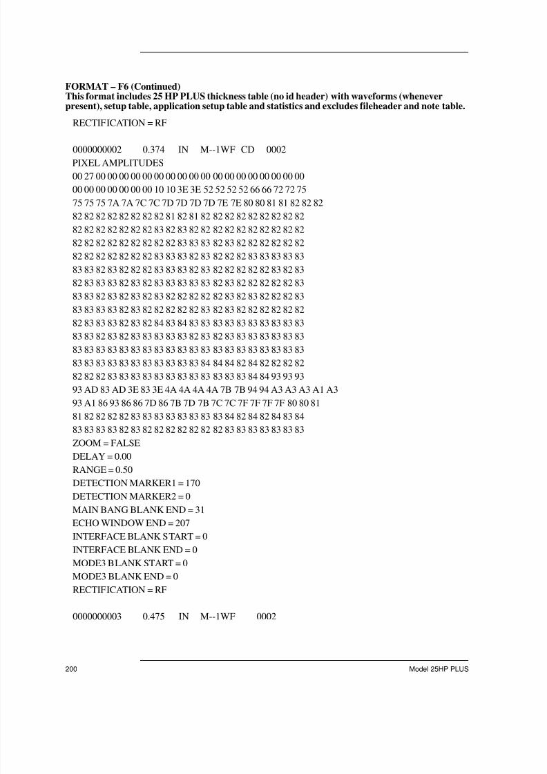
7/23/2019 Panametrics 25HP Plus Manual
http://slidepdf.com/reader/full/panametrics-25hp-plus-manual 200/230
200 Model 25HP PLUS
RECTIFICATION = RF
0000000002 0.374 IN M--1WF CD 0002
PIXEL AMPLITUDES
00 27 00 00 00 00 00 00 00 00 00 00 00 00 00 00 00 00 00 00
00 00 00 00 00 00 00 10 10 3E 3E 52 52 52 52 66 66 72 72 75
75 75 75 7A 7A 7C 7C 7D 7D 7D 7D 7E 7E 80 80 81 81 82 82 82
82 82 82 82 82 82 82 82 81 82 81 82 82 82 82 82 82 82 82 82
82 82 82 82 82 82 82 83 82 83 82 82 82 82 82 82 82 82 82 82
82 82 82 82 82 82 82 82 82 83 83 83 82 83 82 82 82 82 82 82
82 82 82 82 82 82 82 83 83 83 82 83 82 82 82 83 83 83 83 83
83 83 82 83 82 82 82 83 83 83 82 83 82 82 82 82 82 83 82 83 82 83 83 83 82 83 82 83 83 83 83 83 82 83 82 82 82 82 82 83
83 83 82 83 82 83 82 83 82 82 82 82 82 83 82 83 82 82 82 83
83 83 83 83 82 83 82 82 82 82 82 83 82 83 82 82 82 82 82 82
82 83 83 83 82 83 82 84 83 84 83 83 83 83 83 83 83 83 83 83
83 83 82 83 82 83 83 83 83 83 82 83 82 83 83 83 83 83 83 83
83 83 83 83 83 83 83 83 83 83 83 83 83 83 83 83 83 83 83 83
83 83 83 83 83 83 83 83 83 83 83 84 84 84 82 84 82 82 82 82
82 82 82 83 83 83 83 83 83 83 83 83 83 83 83 84 84 93 93 93
93 AD 83 AD 3E 83 3E 4A 4A 4A 4A 7B 7B 94 94 A3 A3 A3 A1 A3
93 A1 86 93 86 86 7D 86 7B 7D 7B 7C 7C 7F 7F 7F 7F 80 80 81 81 82 82 82 82 83 83 83 83 83 83 83 83 84 82 84 82 84 83 84
83 83 83 83 82 83 82 82 82 82 82 82 82 83 83 83 83 83 83 83
ZOOM = FALSE
DELAY = 0.00
RANGE = 0.50
DETECTION MARKER1 = 170
DETECTION MARKER2 = 0
MAIN BANG BLANK END = 31
ECHO WINDOW END = 207
INTERFACE BLANK START = 0
INTERFACE BLANK END = 0
MODE3 BLANK START = 0
MODE3 BLANK END = 0
RECTIFICATION = RF
0000000003 0.475 IN M--1WF 0002
FORMAT – F6 (Continued)This format includes 25 HP PLUS thickness table (no id header) with waveforms (wheneverpresent), setup table, application setup table and statistics and excludes fileheader and note table.

7/23/2019 Panametrics 25HP Plus Manual
http://slidepdf.com/reader/full/panametrics-25hp-plus-manual 201/230
Appendix D - Data Output Format
910-232B 201
PIXEL AMPLITUDES
00 28 00 00 00 00 00 00 00 00 00 00 00 00 00 40 40 56 56 71 71 76 76 7B 7B 7E 7E 80 80 81 81 82 82 82 81 82 81 82 82 82
82 82 81 82 81 82 82 82 82 82 81 82 81 82 82 82 82 82 82 83
82 82 82 83 83 83 83 83 83 83 82 83 82 83 81 83 83 84 83 83
82 83 82 83 82 83 82 83 83 83 83 83 82 83 83 83 83 83 83 83
83 83 83 83 83 83 83 83 83 83 83 83 82 83 82 83 82 83 83 83
83 83 83 84 83 83 83 83 83 84 83 84 83 83 83 83 83 83 83 83
83 83 83 83 83 83 83 83 83 83 83 83 83 83 83 83 82 83 82 83
83 83 83 83 83 83 83 83 83 83 83 83 83 83 83 83 83 83 83 83
82 83 83 83 82 84 82 83 83 84 83 83 83 83 83 83 83 90 90 AB
46 AB 40 72 72 91 91 A2 96 A2 82 96 7D 82 7C 7D 7D 80 80 82 82 83 83 84 84 84 84 84 83 84 83 83 83 83 83 83 83 83 83 83
83 84 84 84 83 84 83 83 83 83 83 84 83 84 83 83 83 83 83 83
83 83 83 83 83 83 83 83 83 83 82 84 82 83 83 83 83 84 83 84
82 83 81 82 81 84 84 85 85 86 84 86 82 84 82 82 82 82 82 83
83 83 83 83 83 84 83 84 83 84 83 84 83 83 83 83 83 83 83 84
83 84 83 84 82 83 82 83 83 83 83 83 83 84 84 84 83 84 83 83
83 83 83 83 83 83 83 83 83 83 83 83 83 83 83 83 83 83 83 84
83 84 83 84 84 85 83 85 83 83 82 83 82 82 82 83 83 83 83 83
82 84 82 83 83 83 83 83 83 84 84 84 84 90 8C 90 67 8C 67 89
ZOOM = FALSE DELAY = 0.00
RANGE = 1.00
DETECTION MARKER1 = 109
DETECTION MARKER2 = 0
MAIN BANG BLANK END = 19
ECHO WINDOW END = 207
INTERFACE BLANK START = 0
INTERFACE BLANK END = 0
MODE3 BLANK START = 0
MODE3 BLANK END = 0
RECTIFICATION = RF
OK
SU # VEL(/uS) DIFF LO-ALM HI-ALM UNITS MEAS-TYPE REF-THK
0002 0.22600 0.000 0.000 25.000 IN THK 0.500
FORMAT – F6 (Continued)This format includes 25 HP PLUS thickness table (no id header) with waveforms (wheneverpresent), setup table, application setup table and statistics and excludes fileheader and note table.

7/23/2019 Panametrics 25HP Plus Manual
http://slidepdf.com/reader/full/panametrics-25hp-plus-manual 202/230
202 Model 25HP PLUS
OK
SETUP NUMBER : 0002 SETUP NAME : DEFM1-5.0/M110
PROBE TYPE : 3
MATERIAL VELOCITY : 0.22600IN/us
ZERO : 210.30
PULSER VOLTAGE : 3
MAXIMUM GAIN : 2736
INITIAL GAIN : 1181
TDG SLOPE : 2489
MAIN BANG BLANK : 18
ECHO WINDOW : 6998 P/R CONFIG : 1
DETECTION MODE : 1
ECHO1 DETECTION : 1
ECHO2 DETECTION : N/A
INTERFACE BLANK : N/A
MODE3 ECHO BLANK : N/A
OK
*** STATISTICS ***
# OF IDS : 3
MEAN : 0.375 IN
MEDIAN : 0.376 IN
STD. DEVIATION : 0.099 IN
# OF HIGH ALARM : 0
% OF HIGH ALARM : 0 %
# OF LOW ALARM : 0
% OF LOW ALARM : 0 %
# OF MINS : 1
MIN. VALUE : 0.277 IN
# OF MAXS : 1
MAX. VALUE : 0.475 IN
OK
FORMAT – F6 (Continued)This format includes 25 HP PLUS thickness table (no id header) with waveforms (wheneverpresent), setup table, application setup table and statistics and excludes fileheader and note table.

7/23/2019 Panametrics 25HP Plus Manual
http://slidepdf.com/reader/full/panametrics-25hp-plus-manual 203/230
Appendix D - Data Output Format
910-232B 203
FORMAT – F7This is in conformance with the 26DL PLUS 16-character id format. This format includes 26DLPLUS thickness table (no id header) in 16-character id format with waveforms (whenever present)
and setup table and note table.0 1 2 3 4 5 6
0123456789012345678901234567890123456789012345678901234567890123456789
0000000001 0.277 IN M--1W- 0002
PIXEL AMPLITUDES
03 00 00 00 00 00 01 15 19 22
23 24 24 25 25 25 25 25 25 25
25 25 25 25 25 25 25 25 25 25
25 25 25 25 25 25 25 26 25 25
25 25 25 25 25 25 25 25 25 25 25 25 25 25 25 25 25 26 25 30
37 37 12 28 32 32 29 27 24 25
25 25 25 25 25 26 26 25 25 25
25 25 25 25 25 25 25 25 25 26
26 26 26 25 25 25 25 25 25 26
ZOOM = FALSE
DELAY = 0.00
RANGE = 0.50
DETECTION MARKER1 = 66
DETECTION MARKER2 = 0 MAIN BANG BLANK END = 15
ECHO WINDOW END = 103
INTERFACE BLANK START = 0
INTERFACE BLANK END = 0
MODE3 BLANK START = 0
MODE3 BLANK END = 0
RECTIFICATION = RF
0000000002 0.374 IN M--1W- 0002
PIXEL AMPLITUDES
02 00 00 00 00 00 00 13 18 22
23 24 24 25 25 25 25 25 25 25
25 25 25 25 25 25 25 25 25 25
25 25 25 25 25 25 25 25 25 25
25 25 25 25 25 25 25 25 25 25
25 25 25 25 25 25 26 26 25 25

7/23/2019 Panametrics 25HP Plus Manual
http://slidepdf.com/reader/full/panametrics-25hp-plus-manual 204/230
204 Model 25HP PLUS
25 25 25 25 25 25 25 25 25 25 25 25 26 26 25 25 25 25 26 29
36 25 23 33 33 33 26 24 24 25
25 25 25 26 26 25 25 25 25 25
ZOOM = FALSE
DELAY = 0.00
RANGE = 0.50
DETECTION MARKER1 = 85
DETECTION MARKER2 = 0
MAIN BANG BLANK END = 15
ECHO WINDOW END = 103 INTERFACE BLANK START = 0
INTERFACE BLANK END = 0
MODE3 BLANK START = 0
MODE3 BLANK END = 0
RECTIFICATION = RF
0000000003 0.475 IN M--1W- 0002
PIXEL AMPLITUDES
03 00 00 09 21 23 25 25 25 25
25 25 25 25 25 25 25 25 25 26
25 25 25 25 25 25 25 25 25 25
26 25 26 25 25 25 25 25 25 25
25 25 25 25 25 25 26 26 25 35
35 33 33 25 25 26 26 26 25 25
26 26 26 26 25 25 25 26 25 26
25 26 26 26 25 25 26 26 25 26
26 25 25 26 26 25 25 25 25 26
26 26 25 25 25 26 25 26 29 28
ZOOM = FALSE
DELAY = 0.00
RANGE = 1.00
DETECTION MARKER1 = 54
DETECTION MARKER2 = 0
MAIN BANG BLANK END = 9
ECHO WINDOW END = 103
INTERFACE BLANK START = 0
INTERFACE BLANK END = 0
FORMAT – F7 (Continued)This is in conformance with the 26DL PLUS 16-character id format. This format includes 26DLPLUS thickness table (no id header) in 16-character id format with waveforms (whenever present)and setup table and note table.

7/23/2019 Panametrics 25HP Plus Manual
http://slidepdf.com/reader/full/panametrics-25hp-plus-manual 205/230
Appendix D - Data Output Format
910-232B 205
MODE3 BLANK START = 0 MODE3 BLANK END = 0
RECTIFICATION = RF
OK
SU # VEL(/uS) DIFF LO-ALM HI-ALM UNITS MEAS-TYPE REF-THK
0002 0.22600 0.000 0.000 25.000 IN THK 0.500
OK
CODE COMMENT A 001
B 002
C 003
D 004
OK
FORMAT – F7 (Continued)This is in conformance with the 26DL PLUS 16-character id format. This format includes 26DLPLUS thickness table (no id header) in 16-character id format with waveforms (whenever present)and setup table and note table.

7/23/2019 Panametrics 25HP Plus Manual
http://slidepdf.com/reader/full/panametrics-25hp-plus-manual 206/230
206 Model 25HP PLUS
FORMAT – F8This is in conformance with the 26DL PLUS 16-character id format. This format includes 26DLPLUS thickness table (no id header) in 16-character id format without waveforms, setup table and
note table.0 1 2 3 4 5 6
0123456789012345678901234567890123456789012345678901234567890123456789
0000000001 0.277 IN M--1W- 0002
0000000002 0.374 IN M--1W- 0002
0000000003 0.475 IN M--1W- 0002
OK
SU # VEL(/uS) DIFF LO-ALM HI-ALM UNITS MEAS-TYPE REF-THK
0002 0.22600 0.000 0.000 25.000 IN THK 0.500 OK
CODE COMMENT
A 001
B 002
C 003
D 004
OK

7/23/2019 Panametrics 25HP Plus Manual
http://slidepdf.com/reader/full/panametrics-25hp-plus-manual 207/230
Appendix D - Data Output Format
910-232B 207
FORMAT – F9This is in conformance with the 26DL PLUS 12-character id format. This format includes 26DLPLUS thickness table with waveforms (whenever present) in 12-character id format and setup
table.0 1 2 3 4 5 6
0123456789012345678901234567890123456789012345678901234567890123456789
IDENTIFIER THICKNESS UNITS FLAGS SU #
0000000001 0.277 IN M--1WA 0002
PIXEL AMPLITUDES
03 00 00 00 00 00 01 15 19 22
23 24 24 25 25 25 25 25 25 25
25 25 25 25 25 25 25 25 25 25
25 25 25 25 25 25 25 26 25 25 25 25 25 25 25 25 25 25 25 25
25 25 25 25 25 25 25 26 25 30
37 37 12 28 32 32 29 27 24 25
25 25 25 25 25 26 26 25 25 25
25 25 25 25 25 25 25 25 25 26
26 26 26 25 25 25 25 25 25 26
ZOOM = FALSE
DELAY = 0.00
RANGE = 0.50
DETECTION MARKER1 = 66 DETECTION MARKER2 = 0
MAIN BANG BLANK END = 15
ECHO WINDOW END = 103
INTERFACE BLANK START = 0
INTERFACE BLANK END = 0
MODE3 BLANK START = 0
MODE3 BLANK END = 0
RECTIFICATION = RF
0000000002 0.374 IN M--1WC 0002
PIXEL AMPLITUDES
02 00 00 00 00 00 00 13 18 22
23 24 24 25 25 25 25 25 25 25
25 25 25 25 25 25 25 25 25 25
25 25 25 25 25 25 25 25 25 25
25 25 25 25 25 25 25 25 25 25

7/23/2019 Panametrics 25HP Plus Manual
http://slidepdf.com/reader/full/panametrics-25hp-plus-manual 208/230
208 Model 25HP PLUS
25 25 25 25 25 25 26 26 25 25 25 25 25 25 25 25 25 25 25 25
25 25 26 26 25 25 25 25 26 29
36 25 23 33 33 33 26 24 24 25
25 25 25 26 26 25 25 25 25 25
ZOOM = FALSE
DELAY = 0.00
RANGE = 0.50
DETECTION MARKER1 = 85
DETECTION MARKER2 = 0
MAIN BANG BLANK END = 15 ECHO WINDOW END = 103
INTERFACE BLANK START = 0
INTERFACE BLANK END = 0
MODE3 BLANK START = 0
MODE3 BLANK END = 0
RECTIFICATION = RF
0000000003 0.475 IN M--1W- 0002
PIXEL AMPLITUDES
03 00 00 09 21 23 25 25 25 25
25 25 25 25 25 25 25 25 25 26
25 25 25 25 25 25 25 25 25 25
26 25 26 25 25 25 25 25 25 25
25 25 25 25 25 25 26 26 25 35
35 33 33 25 25 26 26 26 25 25
26 26 26 26 25 25 25 26 25 26
25 26 26 26 25 25 26 26 25 26
26 25 25 26 26 25 25 25 25 26
26 26 25 25 25 26 25 26 29 28
ZOOM = FALSE
DELAY = 0.00
RANGE = 1.00
DETECTION MARKER1 = 54
DETECTION MARKER2 = 0
MAIN BANG BLANK END = 9
ECHO WINDOW END = 103
INTERFACE BLANK START = 0
FORMAT – F9 (Continued)This is in conformance with the 26DL PLUS 12-character id format. This format includes 26DLPLUS thickness table with waveforms (whenever present) in 12-character id format and setuptable.

7/23/2019 Panametrics 25HP Plus Manual
http://slidepdf.com/reader/full/panametrics-25hp-plus-manual 209/230
Appendix D - Data Output Format
910-232B 209
INTERFACE BLANK END = 0 MODE3 BLANK START = 0
MODE3 BLANK END = 0
RECTIFICATION = RF
OK
SU # VEL(/uS) DIFF LO-ALM HI-ALM UNITS MEAS-TYPE REF-THK
0002 0.22600 0.000 0.000 25.000 IN THK 0.500
OK
FORMAT – F9 (Continued)This is in conformance with the 26DL PLUS 12-character id format. This format includes 26DLPLUS thickness table with waveforms (whenever present) in 12-character id format and setuptable.

7/23/2019 Panametrics 25HP Plus Manual
http://slidepdf.com/reader/full/panametrics-25hp-plus-manual 210/230
210 Model 25HP PLUS
FORMAT – F10This is in conformance with the 26DL PLUS 12-character id format. This format includes 26DLPLUS thickness table without waveforms in 12- character id format and setup table.
0 1 2 3 4 5 6
0123456789012345678901234567890123456789012345678901234567890123456789
IDENTIFIER THICKNESS UNITS FLAGS SU #
0000000001 0.277 IN M--1WA 0002
0000000002 0.374 IN M--1WC 0002
0000000003 0.475 IN M--1W- 0002
OK
SU # VEL(/uS) DIFF LO-ALM HI-ALM UNITS MEAS-TYPE REF-THK
0002 0.22600 0.000 0.000 25.000 IN THK 0.500 OK

7/23/2019 Panametrics 25HP Plus Manual
http://slidepdf.com/reader/full/panametrics-25hp-plus-manual 211/230
Appendix D - Data Output Format
910-232B 211
Thickness Table: A thickness table consists of a header line, thickness data andwaveform data. The thickness table has some differences in the different formats. Thereare six flags associated with each thickness reading in the Thickness Table. In formats
F-1 and F-2, the sixth flag is DN Flag; while in format F-5, the sixth flag represents a
comment code. These are positional and their possible values are shown below:
A single line consisting of the text “OK” immediately follows the end of the ThicknessTable.
Flag Flag Condition Remarks
FLAG #1 M = Normal MeasL = Normal LOS
Measured EchoLoss Of Signal
FLAG #2 Differential ModeD-Differential Moded -% Differential Mode
Standard AlarmA-Alarm ModeH-High AlarmL-Low Alarm
Percent Previous Modep-Alarm Moder-Reduction Alarmg-Growth Alarm
Absolute Previous Alarm ModeP-Alarm modeR-Reduction Alarm
G-Growth Alarm
FLAG #3 - = None
m = MinimumM = Maximum
No Min., No Max.
Minimum readingMaximum reading
FLAG #4 - = Default GainG = Gain Mode
Default Gain; AGC WaveformGain Changed manually
FLAG #5 - = No WaveformW = Waveform
No stored waveformWaveform stored
FLAG #6(F1, F2)
T = DN TrueF = DN False
Downloaded or created IDData stored
FLAG #6(F5 to F8)
- = No CommentA thru Z = Comment Code
No comment storedComment code
Table 18 Flag Conditions

7/23/2019 Panametrics 25HP Plus Manual
http://slidepdf.com/reader/full/panametrics-25hp-plus-manual 212/230
212 Model 25HP PLUS
Setup Table: This table consists of a header line followed by 1 to 32 data lines. There isone data line for each unique setup listed in the thickness table. In general, manythicknesses/waveforms may share a common setup. The number of setups is limited to
64. When the setup table is full, any new setups are allocated the #00 and this entry in
the setup table indicates such status. Setup table has some differences in the differentformats.
A blank line precedes the Setup Table.

7/23/2019 Panametrics 25HP Plus Manual
http://slidepdf.com/reader/full/panametrics-25hp-plus-manual 213/230
Appendix E - Remote Control Via RS-232
910-232B 213
Appendix E - Remote Control Via RS-232
You can control the Model 25HP PLUS from an external computer or programmablecontroller using the serial RS-232 cable. In addition, you can also perform most gage
keypad functions by transmitting the proper commands to the gage over the serial cable.These functions include setup, calibration, and data storage and retrieval. Each Model25HP PLUS key has a corresponding remote command. For example, you can load acomplete setup and calibration parameters to the gage from a computer at the beginning ofeach workshift without performing a manual setup and calibration.
Another computer control feature is the on-line or robotic thickness measurement andreporting. A computer or machine controller directs the positioning of an ultrasonictransducer on a robot arm while at the same time electronically entering the keys on theModel 25HP PLUS. For example, an unattended computer could set up and change toDifferential Measurement mode, change resolution, calibrate and/or set differentvelocity values, or read the various thickness values. The controlling program can repeatthe same sequence of steps for each product to be measured.
The command set is divided in two formats:
Multi-Character commands: Multi-Character commands consist of two or morecharacters and maybe followed by a terminator.
Single-Character commands: Single-Character commands consist of a single characterwith no terminator, used to imitate keystrokes on the gage remotely.
To change the command formats, follow these steps.
1. Press [2ndF], [0] (SP MODE).
2. Press [ ] and [ ] to highlight the Communication option. Press [ENTER].
3. Press [ ] and [ ] to highlight the Comm Protocol option.
4. Press [ ] and [ ] to toggle between the SINGLE or MULTI character command.Press [ENTER].
Multi-character Commands
This section describes all Multi-Character commands and illustrates the syntax used witheach command.
Note: Commands are case sensitive and, if appropriate, terminated with a carriage-return line-feed pair i.e., ( /r/n ) .

7/23/2019 Panametrics 25HP Plus Manual
http://slidepdf.com/reader/full/panametrics-25hp-plus-manual 214/230
214 Model 25HP PLUS
File Directory
This command instructs the gage to send to the host, (the sender of the command) the filedirectory that exists on the gage. Refer to Panametrics-NDTTM document 25 series FTP for details on the format received data.
Command FORMAT: FILEDIR?\r\n
\r is an escape sequence for carriage return.
\n is an escape sequence for line-feed.
File Read
This command instructs the gage to send to the host, (the sender of the command) a filethat exists on the gage. Refer to Panametrics-NDT document 25 series FTP for details onthe file received by the host.
Command FORMAT: FILEREAD?\2\r\n
FREAD INFO block
\3
Notes:
\2 is an escape sequence meaning the ASCII data 2 hex, 2 decimal or the STXcharacter.
\3 is an escape sequence meaning the ASCII data 3 hex, 3 decimal or the ETXcharacter.
See Panametrics-NDT document 25 series FTP for the definition of a FREAD INFO block,
File Write
This command instructs the gage to prepare for receiving a file that is sent by the host, (thesender of the command). Refer to Panametrics-NDTTM document 25 series FTP for detailson the file data format.
Command FORMAT: FILEWRITE=\2\r\n
TRANSMISSION INFO block
FILE HEADER INFO block
ID INFO block
SU TABLE INFO block
NOTE TABLE INFO block
\3
Notes:
\2 is an escape sequence meaning the ASCII data 2 hex, 2 decimal or the STXcharacter.

7/23/2019 Panametrics 25HP Plus Manual
http://slidepdf.com/reader/full/panametrics-25hp-plus-manual 215/230
Appendix E - Remote Control Via RS-232
910-232B 215
\3 is an escape sequence meaning the ASCII data 3 hex, 3 decimal or the ETXcharacter.
See Panametrics-NDTTM document 25 series FTP for the definition of the required INFO blocks used,
File Delete
This command instructs the gage to delete a file that is on the gage. Refer to Panametrics-NDT document 25 series FTP for definition of filedelete packet.
Command FORMAT: FILEDELETE\2\r\n
FILEDELETE Info Block
\3
Notes:
\2 is an escape sequence meaning the ASCII data 2 hex, 2 decimal or the STX
character.
\3 is an escape sequence meaning the ASCII data 3 hex, 3 decimal or the ETXcharacter.
See Panametrics-NDT document 25 series FTP for the definition of the required INFO blocks used,
Communication ProtocolChange
This command instructs the gage to change the communication protocol from multiple tosingle.
Command FORMAT: PROTO=SINGLE\r\n
Application Setup Directory
This command instructs the gage to send to the host, (the sender of the command) theactive setup and all of the user setups that exists on the gage. Refer to Panametrics-NDTTM document 25 series FTP for details on the format received data i.e.APP_SU_TABLE_INFO block
Command FORMAT: APPSUDIR?\r\n
\r is an escape sequence for carriage return.
\n is an escape sequence for line-feed.
Application Setup Read
This command instructs the gage to send to the host, (the sender of the command) theapplication setup that is requested. Refer to Panametrics-NDT document 25 series FTP for details on the APP SU INDEX block and APP SU INFO block sent to the host.

7/23/2019 Panametrics 25HP Plus Manual
http://slidepdf.com/reader/full/panametrics-25hp-plus-manual 216/230
216 Model 25HP PLUS
Command FORMAT: APPSUREAD?\2\r\n
APP SU INDEX block
\3
\r is an escape sequence for carriage return.
\n is an escape sequence for line-feed.
\2 is an escape sequence meaning the ASCII data 2 hex, 2 decimal or the STXcharacter.
\3 is an escape sequence meaning the ASCII data 3 hex, 3 decimal or the ETXcharacter.
Application Setup WriteThis command instructs the gage to receive an application setup that is sent to the host,(the sender of the command).Refer to Panametrics-NDT document 25 series FTP fordetails on the APP SU INDEX block and APP SU INFO block sent to the host.
Command FORMAT: APPSUWRITE=\2\r\n
APP SU INDEX block
APP SU INFO block
\3
\r is an escape sequence for carriage return.
\ n is an escape sequence for line-feed.
\2 is an escape sequence meaning the ASCII data 2 hex, 2 decimal or the STXcharacter.
\3 is an escape sequence meaning the ASCII data 3 hex, 3 decimal or the ETXcharacter.
Notes:
Refer to 26DLP manual for further details.
Make Application Setup Active
This command instructs the gage to make the given application setup the activesetup.Refer to Panametrics-NDT document 25 series FTP for details on the APP SUINDEX block.
Command FORMAT: APPSUWRITE=\2\r\n
APP SU INDEX block

7/23/2019 Panametrics 25HP Plus Manual
http://slidepdf.com/reader/full/panametrics-25hp-plus-manual 217/230
Appendix E - Remote Control Via RS-232
910-232B 217
APP SU INFO block
\3
\r is an escape sequence for carriage return. \n is an escape sequence for line-feed.
\2 is an escape sequence meaning the ASCII data 2 hex, 2 decimal or the STXcharacter.
\3 is an escape sequence meaning the ASCII data 3 hex, 3 decimal or the ETXcharacter.
Notes:
Refer to 26DLP manual for further details.
Units Get
This command instructs the gage to send the current units (IN/MM) to the host.
Command FORMAT: UNITS?\r\n
Version Get
This command instructs the gage to send the current software version of the gage to thehost.
Command FORMAT: VER?\r\n
Range Send
This command instructs the gage to do a range send of all of the IDs in the current file tothe host.
Command FORMAT: ntt
Go to Monitor Mode
This command instructs the gage to go to the Monitor mode.
Command FORMAT: MONITOR=GO\r\n
Mode Get
This command instructs the gage to send the current Measurement mode (1,2,3) of thegage to the host.
Command FORMAT: MODE?\r\n

7/23/2019 Panametrics 25HP Plus Manual
http://slidepdf.com/reader/full/panametrics-25hp-plus-manual 218/230
218 Model 25HP PLUS
Single-Character Commands
This section describes all Single-Character commands and illustrates the syntax used witheach command.
Command Name COMMAND Syntax CorrespondingGage KeyStroke(s)ASCII
CharacterDec Hex
Setup Adjust ! 33 21 [2nd], [1]
Units # 35 23 [2nd], [3]
Meas Rate $ 36 24 [2nd], [4]
Min/Max % 37 25 [2nd], [5]
Hold/Blank & 38 26 [2nd], [7]Diff ( 40 28 [2nd], [9]
Sp Mode ) 41 29 [2nd], [0]
Alarm * 42 2A [2nd], [8]
Number 0 0 48 30 [0]
Number 1 1 49 31 [1]
Number 2 2 50 32 [2]
Number 3 3 51 33 [3]
Number 4 4 52 34 [4]
Number 5 5 53 35 [5]
Number 6 6 54 36 [6]
Number 7 7 55 37 [7]
Number 8 8 56 38 [8]
Number 9 9 57 39 [9]
Resolution @ 64 40 [2nd], [2]
LCD Adjust B 66 42 [2nd], [Light]
Cal Lock C 67 43 [6], [3]Simultaneously
Slew Down D 68 44 [!]
Clear Memory E 69 45 [2nd], [File]
Table 19 Command Syntax

7/23/2019 Panametrics 25HP Plus Manual
http://slidepdf.com/reader/full/panametrics-25hp-plus-manual 219/230
Appendix E - Remote Control Via RS-232
910-232B 219
Rectification F 70 46 [2nd], [Freeze]
Gain Optimization G 71 47 [2nd], [Gain]
Clear Memory E 69 45 [2nd], [File]
Rectification F 70 46 [2nd], [Freeze]
Gain Optimization G 71 47 [2nd], [Gain]
Echo to Echo H 72 48 [2nd], [Zoom]
Note I 73 49 [2nd], [ID#]
Slew Left L 76 4C ["]
Escape M 77 4D [2nd], [Meas]
Slew Right R 82 52 [# ]
Print T 84 54 [2nd], [Send]
Slew up U 85 55 [$]
Zoom Z 90 5A [Zoom]
File \ 92 5C [File]
Status ^ 94 5E [2nd], [6]
Alarm a 97 61 [2nd], [8]Light b 98 62 [Light]
Cal c 99 63 [Cal]
Diff d 100 64 [2nd], [9]
Clear Memory e 101 65 [2nd], [FILE]
Freeze f 102 66 [Freeze]
Recall Setup g 103 67 [RECALLSETUP]
ID i 105 69 [ID#]Delay l 108 6C [2nd], [Range]
Meas m 109 6D [Meas]
Send n 110 6E [Send]
Command Name COMMAND Syntax CorrespondingGage KeyStroke(s)ASCII
CharacterDec Hex
Table 19 Command Syntax (Continued) (Continued)

7/23/2019 Panametrics 25HP Plus Manual
http://slidepdf.com/reader/full/panametrics-25hp-plus-manual 220/230
220 Model 25HP PLUS
Enter p 112 70 [Enter]
Range r 114 72 [Range]
Save s 115 73 [Save]
Single Send t 116 74 [Send]
Units u 117 75 [2nd], [3]
Velocity v 118 76 [Vel]
Raw Data Send w 119 77 None
Setup Adjust x 120 78 [2nd], [1]
Zero z 122 7A [Zero]
CommunicationProtocol change
+ 43 2B None
Note: Changescomm protocolfrom single tomulticharacter.
Command Name COMMAND Syntax CorrespondingGage KeyStroke(s)ASCII
CharacterDec Hex
Table 19 Command Syntax (Continued) (Continued)

7/23/2019 Panametrics 25HP Plus Manual
http://slidepdf.com/reader/full/panametrics-25hp-plus-manual 221/230
Appendix F - Accessories and Replacement Parts
910-232B 221
Appendix F - Accessories and Replacement Parts
Description Part #
Carrying Case 36DLPLUS/CC
Heavy Duty Carrying Case Assembly 26DLPLUS/HDC
Small Protective Pouch Kit, including chestharness and waist strap
36DLP/SPC/KIT
Manual 910-232
Pocket Instruction Card 25DLP/PIC
Interface ProgramCD-ROM (Standard)
3 1/2" DD Diskette (Upon Request)
WIN25DLPLUS
Printer-Portable, Battery or 115 VAC,Thermal,80 Column
36PR
Printer-Portable, Battery or 230 VAC,Thermal, 80 Column
36PRE
Paper for Printer, 1 box (5 rolls) 80PP
Dummy Plug Set 36DLP/PS
Battery-NiCad Rechargeable Alkaline BatteryClip
36DLP/BP36DLP/AA
Software Upgrade 25HPP/SU
Remote Save Handswitch 36DLP/RSA/H
Remote Send Handswitch 36DLP/RSE/H
Remote Save Footswitch 36DLP/RSA
Remote Send Footswitch 36DLP/RSE
Extended Warranty – 1 Year 25HPP/EW
Bar Code Wand 36DLP/BCW
RS-232 I/O CABLES
9-Pin Female “D” (6 feet) 36DLC/9F-6
9-Pin Female “D” (12 feet) 36DLC/9F-12
25-Pin Male “D” (6 feet) 36DLC/25M-6
25-Pin Male “D” (12 feet) 36DLC/25M-12
Table 20 Accessories and Replacement Parts

7/23/2019 Panametrics 25HP Plus Manual
http://slidepdf.com/reader/full/panametrics-25hp-plus-manual 222/230
222 Model 25HP PLUS
25-Pin Female “D” (6 feet) 36DLC/25F-6
25-Pin Female “D” (12 feet) 36DLC/25F-12
Cable for Portable Printers 36DLC/9M/PR-6
UNIVERSAL CHARGER/AC ADAPTERS 36CAPLUS
North America, South America, Japan, Korea 2111
European–Austria, Belgium, Finland, France,Germany, Netherlands, Sweden, Norway, Israel,and Greece
1514
Australia 1515
United Kingdom 1516
Italy 1517
Denmark 1518
India, Pakistan, South Africa, Hong-Kong 1519
COUPLANT
Propylene Glycol Couplant A-2, 2 oz. (.06 liter)
Glycerin Couplant B-2, 2 oz (.06 liter)
Gel Type Couplant D-12, 12 oz. (.35 liter)
Ultratherm-High Temp up to 1000°F Couplant E-2, 2 oz. (.06 liter)
Medium Temp up to 500°F Couplant F-2, 2 oz. (.06 liter)
TEST BLOCKS
5-Step, 1018 SteelEnglish Units; .100", .200", .300", .400", .500"
2214E
5-Step, 1018 SteelMetric Units; 2.5, 5, 7.5, 10, 12.5 mm
2214M
5-Step, AluminumEnglish Units; .100", .200", .300", .400", .500"
2213E
4-Step, 1018 SteelEnglish Units; .250", .500", .750", 1.500" 2212E
2-Step, 303 Stainless SteelEnglish Units; .050", .1500"Metric Units; 1, 15 mm
2218E2218M
Description Part #
Table 20 Accessories and Replacement Parts (Continued)

7/23/2019 Panametrics 25HP Plus Manual
http://slidepdf.com/reader/full/panametrics-25hp-plus-manual 223/230
Appendix F - Accessories and Replacement Parts
910-232B 223
2-Step, 303 Stainless Steel,English Units; .200", 1.500"
Metric Units; 5, 30 mm
2219E2219M
Description Part #
Table 20 Accessories and Replacement Parts (Continued)

7/23/2019 Panametrics 25HP Plus Manual
http://slidepdf.com/reader/full/panametrics-25hp-plus-manual 224/230
224 Model 25HP PLUS

7/23/2019 Panametrics 25HP Plus Manual
http://slidepdf.com/reader/full/panametrics-25hp-plus-manual 225/230
910-232B 225
Index
Index
Numerics
2-D Matrix Grid file type 117–1212-D Matrix Grid with Custom
Point file type 121–1243-D Custom file type 127–1303-D Matrix Grid file type 124–127
A
Accessories and replacementparts 221–223
AlarmHigh/Low 62
Previous Thickness 64–67Standard 62–64
Application setups 177Audience 16Auto Zero 43–44
B
Backlight 54, 72Bar Code Wand 145–146Battery
AA alkaline 29, 31
charging 30internal 6V 29NiCad battery pack 29replacing 30status meter 30troubleshooting 164
Beeper tone 70Blank mode 67
C
Calibrating 44, 177single point 48two point 48–49Velocity and Zero 45–46Velocity only 46–47Zero only 47–48
Calibration lock 68Caliper settings 80
Chargertoubleshooting 164
Clock 84Comment table
creating or editing from acomputer 135
creating or editing from the Model25DL PLUS 135–136
deleting comments 136Comments 104–105
saving 139Communication mode 77–78Communication parameters 155–156
Communication reset 158, 158–159Connector configuration 29, 94Continuous output option 78Creating files
from a computer 107from the Model 25DL PLUS
107–108Custom setups 85
D
Dataerasing data in an active/openfile 143
saving 138Data files
creating 106Data output formats 156–158,
189–211Database
erasing 144–145Datalogger 101–103
comment structure 104–105file name header structure 104file name structure 103identifier (ID number)
structure 103–104organizing 103
Datalogger resets 158DBase reset 159–161

7/23/2019 Panametrics 25HP Plus Manual
http://slidepdf.com/reader/full/panametrics-25hp-plus-manual 226/230
226 Model 25HP PLUS
DBase tracking 79Default setup 40–42Delay function 52–53Detect mode 85–87
Mode 1 85–86Mode 2 86Mode 3 86–87
Diagnostics mode 80, 165–166error status 81, 168hardware control 81hardware status 81, 166–168keypad test 80, 166video display test 81, 166
Differential modeNormal Differential 57–58
Percent Ratio 58Display 28–29Documentation
related documentation 20revision history 20sending comments 20typographic conventions 19
E
Echo 1 Detect 95–96
Echo 2 Detect 95–96Echo Windowviewing 91–93
Edit ID mode 141–143Editing commands 106–107Erasing data 143–145Error messages 164
F
Filecopying 131–132
deleting 132–134editing/renaming 134–135erasing 144opening 130–131
File name header structure 104File name structure 103
File type2-D Matrix Grid 117–1212-D Matrix Grid with
Custom Point 121–124
3-D Custom 127–1303-D Matrix Grid 124–127Incremental 108–111Sequential 111–113Sequential with Custom
Point 113–116Filled trace 71–72Freeze mode 68Full Wave 69
H
Half Wave Negative 69Half Wave Positive 69Help 168Hold mode 67
I
ID number structure 103–104ID overwrite protection 75–76Inactive time 70Incremental file type 108–111
Initial Gaindefining 89
Interface Blank 96–97
K
Key selectionsaving 74
Keypad functions 21–27
L
Language 71
M
M2008 43–44Main Bang Blank
viewing 90–91Maintenance
routine 163
7/23/2019 Panametrics 25HP Plus Manual
http://slidepdf.com/reader/full/panametrics-25hp-plus-manual 227/230
910-232B 227
Index
transducers 164Maximum Gain
defining 88–89Maximum measure mode 29
Maximum thickness mode 61–62MeasType 74–75Measurement
troubleshooting 165Measurement Display Update
Rate 58–60Measurement mode
Mode 1 32Mode 2 32Mode 3 32
Measurement Setup mode 69
Backlight 72Beeper tone 70filled trace 71–72Inactive time 70Language 71Radix Point 71Supervisor Lock 73–74unfilled trace 71–72
Measurement types 39Metric units 69Minimum measure mode 29
Minimum thickness mode 60–61Mode 3 Echo Blank 97–98
N
Notecopying 137–138
P
P/R config 93–94Performance and accuracy 34–36
Probe typedefining 87
Product description 15Pulser power
effects 87–88
Q
Quick setup 43, 76
R
Radix Point 71Range
adjusting 51–52Receiving files from a
computer 153–154Rectification mode 68
Full Wave 69Half Wave Negative 69Half Wave Positive 69
Remote Control
via RS-232 213–220Reports
generating 146–148Resets 81
communication reset 82, 158–159DBase reset 83, 159–161master reset 83–84measurement reset 82
Resolutionthickness 67Time of Flight 67
velocity 67Review ID mode 140–141RS-232 cables 154
S
Sending a range of ID numbersfrom a file 151
Sending a snapshotto a printer 152using the WIN25DL PLUS,
to a computer 152Sending entire files to computer
or printer 150–151Sequential file type 111–113Sequential with Custom Point
file type 113–116Serial communications 154

7/23/2019 Panametrics 25HP Plus Manual
http://slidepdf.com/reader/full/panametrics-25hp-plus-manual 228/230
228 Model 25HP PLUS
Serial interfaceelectrical definition and
data format 188mechanical description 187–188
Setup adjustment 98Setup name
defining 87Setup parameters 99–100Setup, initial 37–38Single send to a computer or
printer 152Sound velocities 185–186SP modes 69Standard editing commands 106–107Supervisor Lock 73–74
T
TDG Slopedefining 90
Technical specifications 169–183battery and charger 181datalogger 173–175display 170functions 175–177general 181
measurement 172–173packaging 169power 169special gage functions 182–183
Theory of operation 31–34Thickness and Waveform
saving 139Thickness measurements 49
making 40
Thickness readingssaving 138
Thickness resolutionchanging 67
Time of Flight (TOF)measurements 51
Time of Flight resolution 67Transducer Setup
uploading/downloading toa computer 154
Transmitting data to a computeror printer 149–150
Typographic conventions 19
U
Unfilled trace 71–72User-Defined setup 40–42
V
Velocity measurements 49Velocity resolution 67
W
Warranty 3WIN25DL PLUS interface
program 161
Z
Zoom mode 28, 53Mode 1 53Mode 2 53–54Mode 3 54

7/23/2019 Panametrics 25HP Plus Manual
http://slidepdf.com/reader/full/panametrics-25hp-plus-manual 229/230
Documentation Comments
Olympus NDTTM is always interested in improving its documentation. Please completethis questionnaire and return your responses to:
Olympus NDTWaltham, MAAttention: Marketing Dept., Technical Publications
You can also email your comments to: [email protected].
Thank you for helping us improve our documentation!
Note: The following questionnaire is adapted from the “Judging Form” from theBoston Chapter, Society for Technical Communication, TechnicalPublications Competition, and “Revision Checklist” from John Lannon’sTechnical Writing, Seventh Edition (Addison Wesley Longman, 1997).
Document title : _____________________________________________________
Document number: __________________________________________________
Documentation Usability Ratings
In the sections that follow, please rate the usability of the document according to thefollowing rating system:
1 - Poor 2 - Below Average 3 - Average 4 - Above Average 5 - Excellent
Audience and purpose
Is the purpose of this manual clearly stated? 1 2 3 4 5
Does the document fulfill the purpose? 1 2 3 4 5
Is the audience clearly defined? 1 2 3 4 5
Does the document meet the audience’s needs? 1 2 3 4 5
Organization
Do the instructions follow the exact sequence of steps? 1 2 3 4 5
Is the organization appropriate and logical at all levels? 1 2 3 4 5
Are the headings specific and helpful? 1 2 3 4 5
Is the Table of Contents complete and useful? 1 2 3 4 5
Is the index comprehensive, easy to use, and cross-referenced? 1 2 3 4 5
Content
Do explanations enable readers to understand what to do? 1 2 3 4 5
Do notes, cautions, or warnings appear whenever needed,in the appropriate place? 1 2 3 4 5

7/23/2019 Panametrics 25HP Plus Manual
http://slidepdf.com/reader/full/panametrics-25hp-plus-manual 230/230
Is everything accurate? 1 2 3 4 5
Are the main points properly stressed? 1 2 3 4 5
Are there sufficient helpful examples? 1 2 3 4 5
Writing and Editing
Is the reading level appropriate to the audience? 1 2 3 4 5
Are the tone and style appropriate for the purpose and audience? 1 2 3 4 5
Is terminology consistent? 1 2 3 4 5
A t lli d t ti t? 1 2 3 4 5