Embed Size (px)
Citation preview

Pan Breeder Feederand Male Feeder
Installation and Operators manual
MF513HAugust 2004
Model C2 Plusfor Pan Breeder
Model G Plusfor Male Feeder
Chore-Time Warranty Pan Breeder Feeder
Chore-Time Poultry Production Systems, a division of CTB, Inc., (“Chore-Time”), warrants each new CHORE-TIME® product manufactured by it to be free from defects in material or workmanship for one-year from and after the date of initial installation by or for the original purchaser. If such a defect is found by Chore-Time to exist within the one-year period, Chore-Time will, at its option, (a) repair or replace such product free of charge, F.O.B. the factory of manufacture, or (b) refund to the original purchaser the original purchase price, in lieu of such repair or replacement. Labor costs associated with the replacement or repair of the product are not covered by the Manufacturer.
Additional extended warranties for the equipment and/or systems listed below are provided to the original purchaser as follows (for all other CHORE-TIME® products purchased, the one-year warranty period shall apply):
1. TURBO and RLX fans, less motors - 3 years
2. TURBO fan fiberglass housings, polyethylene cones, and cast aluminum blades - for the life of the product
3. TURBO fan motors and bearings - 2 years
4. TURBO fan components (including plastic shutters) - 3 years
5. Poultry feeder pans that becomes unusable within five years from the date of installation - Warranty prorated after three years usage
6. Rotating centerless augers, excluding applications involving high moisture feed stuffs (exceeding 18%), for ten years from the date of installation. Note: MULTIFLO® and applications involving high moisture feed stuffs are subject to a one-year warranty
7. Chore-Time manufactured roll-formed steel auger tubes for ten years from the date of installation
8. ULTRAFLO® Breeder Feeding System auger and feed trough are warranted for a period of five years from the date of original installation against repeated breakage of the auger or wear-through of the feed trough caused solely by the auger
9. ULTRAPAN® Feeding System augers are warranted for a period of five years from the date of installation againstlely by the auger
Chore-Time Warranty
2 MF513H

Pan Breeder Feeder Chore-Time Warranty
CONDITIONS AND LIMITATIONS1. The product must be installed by and operated in accordance with the instructions published by the
Manufacturer or Warranty will be void.
2. Warranty is void if all components of the system are not original equipment supplied by the Manufacturer.
3. This product must be purchased from and installed by an authorized distributor or certified representative thereof or the Warranty will be void.
4. Malfunctions or failure resulting from misuse, abuse, negligence, alteration, accident, or lack of proper maintenance shall not be considered defects under the Warranty.
5. This Warranty applies only to systems for the care of poultry and livestock. Other applications in industry or commerce are not covered by this Warranty.
Chore-Time shall not be liable for any consequential or special damage which any purchaser may suffer or claim to suffer as a result of any defect in the product. “Consequential” or special damages” as used herein include, but are not limited to, lost or damaged products or goods, costs of transportation, lost sales, lost orders, lost income, increased overhead, labor and incidental costs and operational inefficiencies.
THIS WARRANTY CONSTITUTES THE MANUFACTURER’S ENTIRE AND SOLE WARRANTY AND THIS MANUFACTURER EXPRESSLEY DISCLAIMS ANY AND ALL OTHER WARRANTIES, INCLUDING, BUT NOT LIMITED TO, EXPRESS AND IMPLIED WARRANTIES AS TO MERCHANTIBILITY, FITNESS FOR PARTICULAR PURPOSES SOLD AND DESCRIPTION OR QUALITY OF THE PRODUCT FURNISHED HEREUNDER.
Chore-Time Distributors are not authorized to modify or extend the terms and conditions of this Warranty in any manner or to offer or grant any other warranties for Chore-Time products in addition to those terms expressly stated above.
An officer of CTB, Inc. must authorize any exceptions to this Warranty in writing. Chore-Time reserves the right to change models and specifications at any time without notice or obligation to improve previous models.
Effective: August 2004
Chore-Time Poultry Production Systemsa division of CTB, Inc.
410 N. Higbee Street • Milford, Indiana 46542 • U.S.A.Phone (574) 658-4101 • Fax (877) 730-8825
E-mail: [email protected] • Internet: http//www.ctbinc.com
Thank YouThe employees of Chore-Time would like to thank your for your recent Chore-Time purchase. If a problem should arise, your Chore-Time distributor can supply the necessary information to help you.
*Chore-Time Poultry Feeder Pan Pro Rata Schedule
Year from date of installation during which pan becomes unusable Charge to be paid by the purchaser for replacement.0 - 1 years NO CHARGE1 - 2 years NO CHARGE2 - 3 years NO CHARGE3 - 4 years 4/10 of then current list price4 - 5 years 5/10 of then current list price
MF513H 3
Contents
Topic Page
4
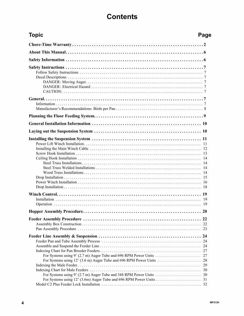
Chore-Time Warranty . . . . . . . . . . . . . . . . . . . . . . . . . . . . . . . . . . . . . . . . . . . . . . . . . . . . . . . . . . . . 2
About This Manual. . . . . . . . . . . . . . . . . . . . . . . . . . . . . . . . . . . . . . . . . . . . . . . . . . . . . . . . . . . . . . . 6
Safety Information . . . . . . . . . . . . . . . . . . . . . . . . . . . . . . . . . . . . . . . . . . . . . . . . . . . . . . . . . . . . . . . 6
Safety Instructions . . . . . . . . . . . . . . . . . . . . . . . . . . . . . . . . . . . . . . . . . . . . . . . . . . . . . . . . . . . . . . . 7Follow Safety Instructions . . . . . . . . . . . . . . . . . . . . . . . . . . . . . . . . . . . . . . . . . . . . . . . . . . . . . . . . . . . . . . 7Decal Descriptions . . . . . . . . . . . . . . . . . . . . . . . . . . . . . . . . . . . . . . . . . . . . . . . . . . . . . . . . . . . . . . . . . . . . 7
DANGER: Moving Auger. . . . . . . . . . . . . . . . . . . . . . . . . . . . . . . . . . . . . . . . . . . . . . . . . . . . . . . . . . . 7DANGER: Electrical Hazard . . . . . . . . . . . . . . . . . . . . . . . . . . . . . . . . . . . . . . . . . . . . . . . . . . . . . . . . 7CAUTION: . . . . . . . . . . . . . . . . . . . . . . . . . . . . . . . . . . . . . . . . . . . . . . . . . . . . . . . . . . . . . . . . . . . . . . 7
General. . . . . . . . . . . . . . . . . . . . . . . . . . . . . . . . . . . . . . . . . . . . . . . . . . . . . . . . . . . . . . . . . . . . . . . . . 7Information . . . . . . . . . . . . . . . . . . . . . . . . . . . . . . . . . . . . . . . . . . . . . . . . . . . . . . . . . . . . . . . . . . . . . . . . . . 7Manufacturer’s Recommendations: Birds per Pan . . . . . . . . . . . . . . . . . . . . . . . . . . . . . . . . . . . . . . . . . . . . 8
Planning the Floor Feeding System. . . . . . . . . . . . . . . . . . . . . . . . . . . . . . . . . . . . . . . . . . . . . . . . . . 9
General Installation Information . . . . . . . . . . . . . . . . . . . . . . . . . . . . . . . . . . . . . . . . . . . . . . . . . . 10
Laying out the Suspension System . . . . . . . . . . . . . . . . . . . . . . . . . . . . . . . . . . . . . . . . . . . . . . . . . 10
Installing the Suspension System . . . . . . . . . . . . . . . . . . . . . . . . . . . . . . . . . . . . . . . . . . . . . . . . . . 11Power Lift Winch Installation. . . . . . . . . . . . . . . . . . . . . . . . . . . . . . . . . . . . . . . . . . . . . . . . . . . . . . . . . . . 11Installing the Main Winch Cable . . . . . . . . . . . . . . . . . . . . . . . . . . . . . . . . . . . . . . . . . . . . . . . . . . . . . . . . 12Screw Hook Installation . . . . . . . . . . . . . . . . . . . . . . . . . . . . . . . . . . . . . . . . . . . . . . . . . . . . . . . . . . . . . . . 13Ceiling Hook Installation . . . . . . . . . . . . . . . . . . . . . . . . . . . . . . . . . . . . . . . . . . . . . . . . . . . . . . . . . . . . . . 14
Steel Truss Installations. . . . . . . . . . . . . . . . . . . . . . . . . . . . . . . . . . . . . . . . . . . . . . . . . . . . . . . . . . . . 14Steel Truss Welded Installations . . . . . . . . . . . . . . . . . . . . . . . . . . . . . . . . . . . . . . . . . . . . . . . . . . . . . 14Wood Truss Installations . . . . . . . . . . . . . . . . . . . . . . . . . . . . . . . . . . . . . . . . . . . . . . . . . . . . . . . . . . . 14
Drop Installation . . . . . . . . . . . . . . . . . . . . . . . . . . . . . . . . . . . . . . . . . . . . . . . . . . . . . . . . . . . . . . . . . . . . . 15Power Winch Installation . . . . . . . . . . . . . . . . . . . . . . . . . . . . . . . . . . . . . . . . . . . . . . . . . . . . . . . . . . . . . . 16Drop Installation . . . . . . . . . . . . . . . . . . . . . . . . . . . . . . . . . . . . . . . . . . . . . . . . . . . . . . . . . . . . . . . . . . . . . 18
Winch Control. . . . . . . . . . . . . . . . . . . . . . . . . . . . . . . . . . . . . . . . . . . . . . . . . . . . . . . . . . . . . . . . . . 19Installation . . . . . . . . . . . . . . . . . . . . . . . . . . . . . . . . . . . . . . . . . . . . . . . . . . . . . . . . . . . . . . . . . . . . . . . . . 19Operation . . . . . . . . . . . . . . . . . . . . . . . . . . . . . . . . . . . . . . . . . . . . . . . . . . . . . . . . . . . . . . . . . . . . . . . . . . 19
Hopper Assembly Procedure . . . . . . . . . . . . . . . . . . . . . . . . . . . . . . . . . . . . . . . . . . . . . . . . . . . . . . 20
Feeder Assembly Procedure . . . . . . . . . . . . . . . . . . . . . . . . . . . . . . . . . . . . . . . . . . . . . . . . . . . . . . 22Assembly Box Construction . . . . . . . . . . . . . . . . . . . . . . . . . . . . . . . . . . . . . . . . . . . . . . . . . . . . . . . . . . . . 22Pan Assembly Procedure . . . . . . . . . . . . . . . . . . . . . . . . . . . . . . . . . . . . . . . . . . . . . . . . . . . . . . . . . . . . . . 23
Feeder Line Assembly & Suspension . . . . . . . . . . . . . . . . . . . . . . . . . . . . . . . . . . . . . . . . . . . . . . . 24Feeder Pan and Tube Assembly Process . . . . . . . . . . . . . . . . . . . . . . . . . . . . . . . . . . . . . . . . . . . . . . . . . . 24Assemble and Suspend the Feeder Line . . . . . . . . . . . . . . . . . . . . . . . . . . . . . . . . . . . . . . . . . . . . . . . . . . . 24Indexing Chart for Pan Breeder Feeders. . . . . . . . . . . . . . . . . . . . . . . . . . . . . . . . . . . . . . . . . . . . . . . . . . . 27
For Systems using 9’ (2.7 m) Auger Tube and 696 RPM Power Units . . . . . . . . . . . . . . . . . . . . . . . 27For Systems using 12’ (3.6 m) Auger Tube and 696 RPM Power Units . . . . . . . . . . . . . . . . . . . . . . 28
Indexing the Male Feeder . . . . . . . . . . . . . . . . . . . . . . . . . . . . . . . . . . . . . . . . . . . . . . . . . . . . . . . . . . . . . . 29Indexing Chart for Male Feeders . . . . . . . . . . . . . . . . . . . . . . . . . . . . . . . . . . . . . . . . . . . . . . . . . . . . . . . . 30
For Systems using 9’ (2.7 m) Auger Tube and 348 RPM Power Units . . . . . . . . . . . . . . . . . . . . . . . 30For Systems using 12’ (3.6m) Auger Tube and 696 RPM Power Units . . . . . . . . . . . . . . . . . . . . . . . 31
Model C2 Plus Feeder Lock Installation . . . . . . . . . . . . . . . . . . . . . . . . . . . . . . . . . . . . . . . . . . . . . . . . . . 32
MF513H

Contents - continued
Topic Page
Installing the End Control, Boot Assembly, and Auger . . . . . . . . . . . . . . . . . . . . . . . . . . . . . . . . . . . . . . . 33Auger Installation . . . . . . . . . . . . . . . . . . . . . . . . . . . . . . . . . . . . . . . . . . . . . . . . . . . . . . . . . . . . . . . . 34Auger Brazing . . . . . . . . . . . . . . . . . . . . . . . . . . . . . . . . . . . . . . . . . . . . . . . . . . . . . . . . . . . . . . . . . . . 38
Anti-Roost Installation . . . . . . . . . . . . . . . . . . . . . . . . . . . . . . . . . . . . . . . . . . . . . . . . . . . . . . . . . . . . . . . . 39
Feeder Management . . . . . . . . . . . . . . . . . . . . . . . . . . . . . . . . . . . . . . . . . . . . . . . . . . . . . . . . . . . . . 42
Maintenance . . . . . . . . . . . . . . . . . . . . . . . . . . . . . . . . . . . . . . . . . . . . . . . . . . . . . . . . . . . . . . . . . . . 43Floor Feeding System Maintenance . . . . . . . . . . . . . . . . . . . . . . . . . . . . . . . . . . . . . . . . . . . . . . . . . . . . . . 43Gear Head Maintenance . . . . . . . . . . . . . . . . . . . . . . . . . . . . . . . . . . . . . . . . . . . . . . . . . . . . . . . . . . . . . . . 43Mechanical Switch Adjustment procedure for Control Units . . . . . . . . . . . . . . . . . . . . . . . . . . . . . . . . . . 44SENSOR PLUS Sensor Switch Adjustment for Control Units . . . . . . . . . . . . . . . . . . . . . . . . . . . . . . . . . 44Feeder Line . . . . . . . . . . . . . . . . . . . . . . . . . . . . . . . . . . . . . . . . . . . . . . . . . . . . . . . . . . . . . . . . . . . . . . . . . 44Power Lift Winch Maintenance . . . . . . . . . . . . . . . . . . . . . . . . . . . . . . . . . . . . . . . . . . . . . . . . . . . . . . . . . 45
Trouble Shooting the Floor Feeding System . . . . . . . . . . . . . . . . . . . . . . . . . . . . . . . . . . . . . . . . . 46
Wiring Diagrams . . . . . . . . . . . . . . . . . . . . . . . . . . . . . . . . . . . . . . . . . . . . . . . . . . . . . . . . . . . . . . . 47Winch Control Wiring Diagram with 29820-3 Tower Limit Switch . . . . . . . . . . . . . . . . . . . . . . . . . . . . . 47Winch Control Wiring Diagram with 39464 Limit Switch . . . . . . . . . . . . . . . . . . . . . . . . . . . . . . . . . . . . 47Male Feeder System Wiring Diagrams: Single Phase(Ø) . . . . . . . . . . . . . . . . . . . . . . . . . . . . . . . . . . . . . 48
Single Phase(Ø) Wiring Diagram . . . . . . . . . . . . . . . . . . . . . . . . . . . . . . . . . . . . . . . . . . . . . . . . . . . . 48Single Phase(Ø) Wiring Diagram: w/Motor Starter . . . . . . . . . . . . . . . . . . . . . . . . . . . . . . . . . . . . . . 48
Male Feeder System Wiring Diagrams: Three Phase(Ø) . . . . . . . . . . . . . . . . . . . . . . . . . . . . . . . . . . . . . . 49Three Phase(Ø) Wiring Diagram: 220/230 V . . . . . . . . . . . . . . . . . . . . . . . . . . . . . . . . . . . . . . . . . . . 49Three Phase(Ø) Wiring Diagram: 380/415 V . . . . . . . . . . . . . . . . . . . . . . . . . . . . . . . . . . . . . . . . . . . 49
Electric Power Lift Wiring Diagram . . . . . . . . . . . . . . . . . . . . . . . . . . . . . . . . . . . . . . . . . . . . . . . . . . . . . 50
Parts Listing . . . . . . . . . . . . . . . . . . . . . . . . . . . . . . . . . . . . . . . . . . . . . . . . . . . . . . . . . . . . . . . . . . . 51Standard Breeder Pans . . . . . . . . . . . . . . . . . . . . . . . . . . . . . . . . . . . . . . . . . . . . . . . . . . . . . . . . . . . . . . . . 51Standard Breeder Pans with Shut-Off. . . . . . . . . . . . . . . . . . . . . . . . . . . . . . . . . . . . . . . . . . . . . . . . . . . . . 52Shallow G™ Plus Breeder Pans with Slide Shut-Off . . . . . . . . . . . . . . . . . . . . . . . . . . . . . . . . . . . . . . . . . 53Shallow G™ Plus Breeder Pans . . . . . . . . . . . . . . . . . . . . . . . . . . . . . . . . . . . . . . . . . . . . . . . . . . . . . . . . . 54Shallow Breeder Pans . . . . . . . . . . . . . . . . . . . . . . . . . . . . . . . . . . . . . . . . . . . . . . . . . . . . . . . . . . . . . . . . . 5534812 Winch Control Parts Listing . . . . . . . . . . . . . . . . . . . . . . . . . . . . . . . . . . . . . . . . . . . . . . . . . . . . . . 5614613 Switch Box Assembly . . . . . . . . . . . . . . . . . . . . . . . . . . . . . . . . . . . . . . . . . . . . . . . . . . . . . . . . . . . 568798 Switch Assembly . . . . . . . . . . . . . . . . . . . . . . . . . . . . . . . . . . . . . . . . . . . . . . . . . . . . . . . . . . . . . . . . 57Mechanical End Control . . . . . . . . . . . . . . . . . . . . . . . . . . . . . . . . . . . . . . . . . . . . . . . . . . . . . . . . . . . . . . . 58Sensor Plus™ End Control . . . . . . . . . . . . . . . . . . . . . . . . . . . . . . . . . . . . . . . . . . . . . . . . . . . . . . . . . . . . . 60Boot Assemblies . . . . . . . . . . . . . . . . . . . . . . . . . . . . . . . . . . . . . . . . . . . . . . . . . . . . . . . . . . . . . . . . . . . . . 62
Single: Part No. 6822. . . . . . . . . . . . . . . . . . . . . . . . . . . . . . . . . . . . . . . . . . . . . . . . . . . . . . . . . . . . . . 62Twin: Part No. 6824 . . . . . . . . . . . . . . . . . . . . . . . . . . . . . . . . . . . . . . . . . . . . . . . . . . . . . . . . . . . . . . 62
Miscellaneous Suspension Components . . . . . . . . . . . . . . . . . . . . . . . . . . . . . . . . . . . . . . . . . . . . . . . . . . . 6314580 Electric Winch Kit . . . . . . . . . . . . . . . . . . . . . . . . . . . . . . . . . . . . . . . . . . . . . . . . . . . . . . . . . . . . . . 64Feeder Line Components . . . . . . . . . . . . . . . . . . . . . . . . . . . . . . . . . . . . . . . . . . . . . . . . . . . . . . . . . . . . . . 652883 Power Winch . . . . . . . . . . . . . . . . . . . . . . . . . . . . . . . . . . . . . . . . . . . . . . . . . . . . . . . . . . . . . . . . . . . 66Indexing Gauge. . . . . . . . . . . . . . . . . . . . . . . . . . . . . . . . . . . . . . . . . . . . . . . . . . . . . . . . . . . . . . . . . . . . . . 66Power Unit Assemblies. . . . . . . . . . . . . . . . . . . . . . . . . . . . . . . . . . . . . . . . . . . . . . . . . . . . . . . . . . . . . . . . 67
MF513H 5

About This Manual Pan Breeder Feeder
The intent of this manual is to help you in two ways. One is to follow step-by-step in the order of assembly of your product. The other way is for easy reference if you have questions in a particular area.
Important: Read ALL instructions carefully before starting construction. Important: Pay particular attention to all SAFETY information.• Metric measurements are shown in millimeters and in brackets, unless otherwise specified. “ " ” equals inches
and “ ' ” equals feet in English measurements.Examples: 1" [25.4]4' [1 219]
• Optional equipment contains necessary instructions for assembly or operation.
• Very small numbers near an illustration (i.e., 1257-48) are identification of the graphic, not a part number.
Caution, Warning and Danger Decals have been placed on the equipment to warn of potentially dangerous situations. Care should be taken to keep this information intact and easy to read at all times. Replace missing or damaged safety decals immediately.
Using the equipment for purposes other than specified in this manual may cause personal injury and/or damage to the equipment.
Safety–Alert SymbolThis is a safety–alert symbol. When you see this symbol on your equipment, be alert to the potential for personal injury. This equipment is designed to be installed and operated as safely as possible...however, hazards do exist.
Understanding Signal WordsSignal words are used in conjunction with the safety–alert symbol to identify the severity of the warning.
DANGER indicates an imminently hazardous situation which, if not avoided, WILL result in death or serious injury.
WARNING indicates a potentially hazardous situation which, if not avoided, COULD result in death or serious injury.
CAUTION indicates a hazardous situation which, if not avoided, MAY result in minor or moderate injury.
About This Manual
Safety Information
6 MF513H

Pan Breeder Feeder Safety Instructions
Follow Safety InstructionsCarefully read all safety messages in this manual and on your equipment safety signs. Follow recommended precautions and safe operating practices.
Keep safety signs in good condition. Replace missing or damaged safety signs.
Decal DescriptionsDANGER: Moving AugerThis decal is placed on the Panel Weldment.
Severe personal injury will result, if the electrical power is not disconnected, prior to servicing the equipment.
DANGER: Electrical HazardDisconnect electrical power before inspecting or servicing equipment unless maintenance instructions specifically state otherwise.
Ground all electrical equipment for safety.
All electrical wiring must be done by a qualified electrician in accordance with local and national electric codes.
Ground all non-current carrying metal parts to guard against electrical shock.
With the exception of motor overload protection, electrical disconnects and over current protection are not supplied with the equipment.
CAUTION:Use caution when working with the Auger—springing Auger may cause personal injury.
InformationThe Chore-Time Pan Breeder and Male Feeding System has been designed to feed poultry. Using this equipment for any other purpose or in a way not within the operating recommendations specified in this manual will void the warranty and may cause personal injury.
This manual is designed to provide comprehensive planning and installation information. The Table of Contents provides a convenient overview of the information in this manual.
Safety Instructions
General
Manboot 3/98
MF513H 7
Pan Breeder Feeder
8 MF513H
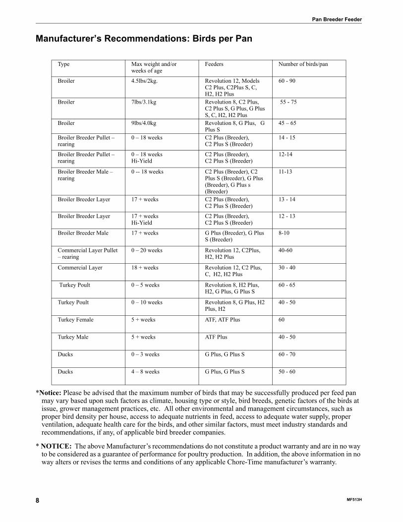
Manufacturer’s Recommendations: Birds per Pan
*Notice: Please be advised that the maximum number of birds that may be successfully produced per feed pan may vary based upon such factors as climate, housing type or style, bird breeds, genetic factors of the birds at issue, grower management practices, etc. All other environmental and management circumstances, such as proper bird density per house, access to adequate nutrients in feed, access to adequate water supply, proper ventilation, adequate health care for the birds, and other similar factors, must meet industry standards and recommendations, if any, of applicable bird breeder companies.
* NOTICE: The above Manufacturer’s recommendations do not constitute a product warranty and are in no way to be considered as a guarantee of performance for poultry production. In addition, the above information in no way alters or revises the terms and conditions of any applicable Chore-Time manufacturer’s warranty.
Type Max weight and/or weeks of age
Feeders Number of birds/pan
Broiler 4.5lbs/2kg. Revolution 12, Models C2 Plus, C2Plus S, C, H2, H2 Plus
60 - 90
Broiler 7lbs/3.1kg Revolution 8, C2 Plus, C2 Plus S, G Plus, G Plus S, C, H2, H2 Plus
55 - 75
Broiler 9lbs/4.0kg Revolution 8, G Plus, G Plus S
45 – 65
Broiler Breeder Pullet – rearing
0 – 18 weeks C2 Plus (Breeder),C2 Plus S (Breeder)
14 - 15
Broiler Breeder Pullet –rearing
0 – 18 weeksHi-Yield
C2 Plus (Breeder),C2 Plus S (Breeder)
12-14
Broiler Breeder Male –rearing
0 -- 18 weeks C2 Plus (Breeder), C2 Plus S (Breeder), G Plus (Breeder), G Plus s (Breeder)
11-13
Broiler Breeder Layer 17 + weeks C2 Plus (Breeder),C2 Plus S (Breeder)
13 - 14
Broiler Breeder Layer 17 + weeksHi-Yield
C2 Plus (Breeder),C2 Plus S (Breeder)
12 - 13
Broiler Breeder Male 17 + weeks G Plus (Breeder), G Plus S (Breeder)
8-10
Commercial Layer Pullet – rearing
0 – 20 weeks Revolution 12, C2Plus, H2, H2 Plus
40-60
Commercial Layer 18 + weeks Revolution 12, C2 Plus, C, H2, H2 Plus
30 - 40
Turkey Poult 0 – 5 weeks Revolution 8, H2 Plus, H2, G Plus, G Plus S
60 - 65
Turkey Poult 0 – 10 weeks Revolution 8, G Plus, H2 Plus, H2
40 - 50
Turkey Female 5 + weeks ATF, ATF Plus 60
Turkey Male 5 + weeks ATF Plus 40 - 50
Ducks 0 – 3 weeks G Plus, G Plus S 60 - 70
Ducks 4 – 8 weeks G Plus, G Plus S 50 - 60

Pan Breeder Feeder Planning the Floor Feeding System
1. Select the House Layout.
Figure 1.Component location diagram for systems up to 400 feet [122 m].A. Systems with line lengths over 400’ [122 m] should be split in the center, as shown in Figure 2. This will
reduce auger running time and eliminate the need for Mid-Line Controls for partial house brooding.
Figure 2. Component location diagram for systems over 400 feet [122 m].
2. Determine the Feed Bin location.3. Determine the Brood Curtain location.4. Determine the location for the End Control Pans. The Feeder Control Pans should be at least 10’ [3 m]
from the Wall or Brood Curtain.5. Determine the distance to the Feeder Line from the Side Wall.6. Determine the distance from the Feed Hoppers to the End Wall for a Straight Line Feeding System.
Planning the Floor Feeding System
1255-68 1/2001
6) Feed Bin
3) Feed Hopper
2) Brood Curtain
5) End Control& Power Unit
1) Control Tube
1) Control Tube
10' [3 m]Minimum
10' [3 m]Minimum
10' [3 m]Minimum
1255-69 1/2001
5) Feed Bin
3) Feed Hoppers
2) Brood Curtain
4) End Control& Power Unit
4) End Control& Power Unit
1) Control Tube
1) Control Tube
1) Control Tube
1) Control Tube
MF513H 9
General Installation Information Pan Breeder Feeder
Please read the installation instructions in this manual prior to beginning the installation. This manual provides the necessary information on the installation, operation, and maintenance of the Chore-Time feeding equipment you have purchased.
The suspension, hopper assembly, feeder line installation, and anti-roost installation is the same for each system, except where noted otherwise. Please pay particularly close attention to insure proper assembly and installation of the equipment.
The Male Feeder use the Model G Plus breeder pan. The male feeder is available in nine foot 1 and 2 hole. The 9 foot tubes utilize the 348 rpm gearhead delivering 17# of feed per minute, also available is a 12 foot 3 hole feeder. The 12 foot feeder utilizes the 696 rpm gearhead delivering 35# of feed per minute.
The female feeder uses the Model C2 Plus breeder pan. The female feeder is available in 9 foot 4 hole and 12 foot 4 hole models using a 696 RPM. Gearhead, delivering approximately 35# per minute [10.6kg] per minute. All rating are based on feed with a density of 40 lbs per cubic foot [640 kg per cubic meter].
Single phase 60 Hz and single and three phase 50 Hz Power Units are available for the Model C2 Plus , G Plus Feeders.
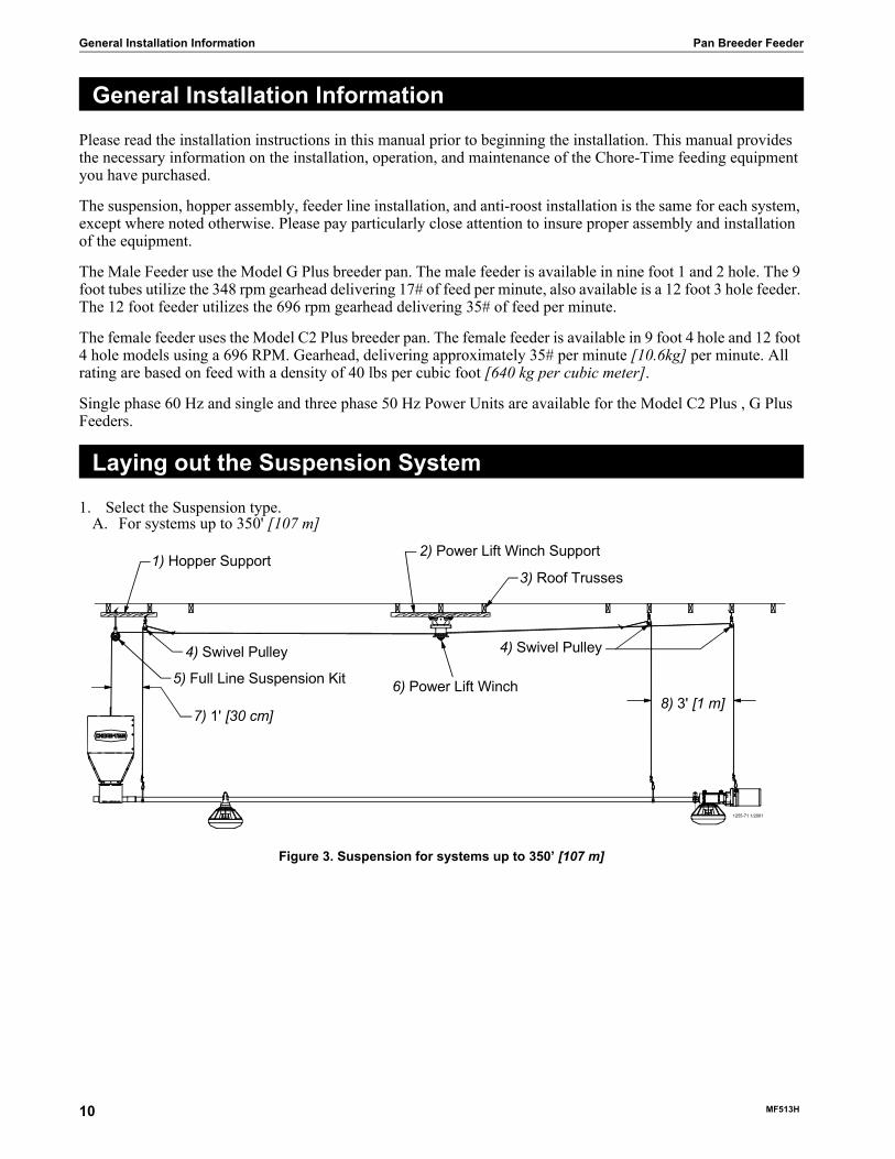
1. Select the Suspension type.A. For systems up to 350' [107 m]
Figure 3. Suspension for systems up to 350’ [107 m]
General Installation Information
Laying out the Suspension System
1255-71 1/2001
4) Swivel Pulley
5) Full Line Suspension Kit
7) 1' [30 cm]
4) Swivel Pulley
6) Power Lift Winch8) 3' [1 m]
1) Hopper Support2) Power Lift Winch Support
3) Roof Trusses
10 MF513H
Pan Breeder Feeder Installing the Suspension System
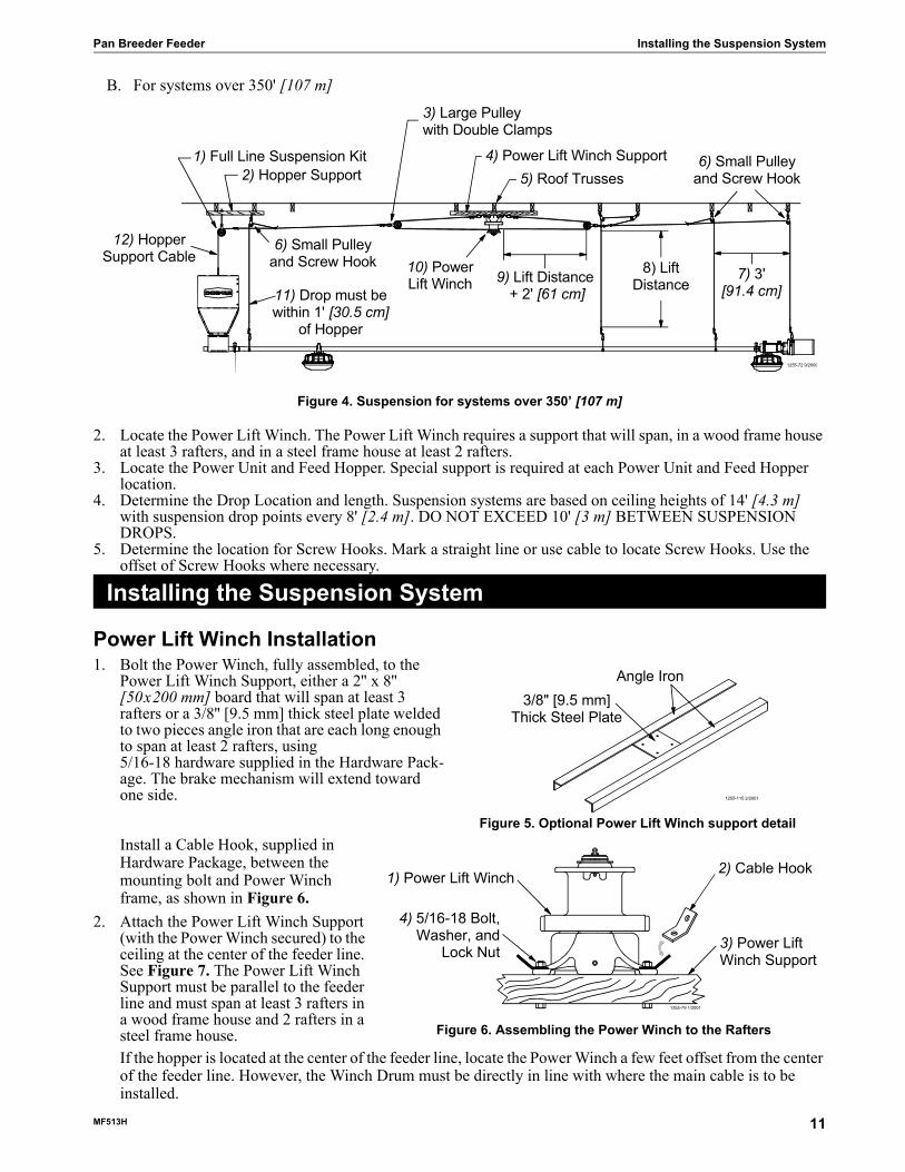
B. For systems over 350' [107 m]
Figure 4. Suspension for systems over 350’ [107 m]
2. Locate the Power Lift Winch. The Power Lift Winch requires a support that will span, in a wood frame house at least 3 rafters, and in a steel frame house at least 2 rafters.
3. Locate the Power Unit and Feed Hopper. Special support is required at each Power Unit and Feed Hopper location.
4. Determine the Drop Location and length. Suspension systems are based on ceiling heights of 14' [4.3 m] with suspension drop points every 8' [2.4 m]. DO NOT EXCEED 10' [3 m] BETWEEN SUSPENSION DROPS.
5. Determine the location for Screw Hooks. Mark a straight line or use cable to locate Screw Hooks. Use the offset of Screw Hooks where necessary.
Power Lift Winch Installation1. Bolt the Power Winch, fully assembled, to the
Power Lift Winch Support, either a 2'' x 8'' [50x200 mm] board that will span at least 3 rafters or a 3/8'' [9.5 mm] thick steel plate welded to two pieces angle iron that are each long enough to span at least 2 rafters, using5/16-18 hardware supplied in the Hardware Pack-age. The brake mechanism will extend toward one side.
Install a Cable Hook, supplied in Hardware Package, between the mounting bolt and Power Winch frame, as shown in Figure 6.
2. Attach the Power Lift Winch Support (with the Power Winch secured) to the ceiling at the center of the feeder line. See Figure 7. The Power Lift Winch Support must be parallel to the feeder line and must span at least 3 rafters in a wood frame house and 2 rafters in a steel frame house.If the hopper is located at the center of the feeder line, locate the Power Winch a few feet offset from the center of the feeder line. However, the Winch Drum must be directly in line with where the main cable is to be installed.
Installing the Suspension System
1) Full Line Suspension Kit
12) HopperSupport Cable
6) Small Pulleyand Screw Hook
3) Large Pulleywith Double Clamps
10) PowerLift Winch 9) Lift Distance
+ 2' [61 cm]
8) LiftDistance
7) 3'[91.4 cm]
6) Small Pulleyand Screw Hook
1255-72 9/2000
11) Drop must bewithin 1' [30.5 cm]
of Hopper
2) Hopper Support4) Power Lift Winch Support
5) Roof Trusses
1255-115 2/2001
Angle Iron3/8" [9.5 mm]
Thick Steel Plate
Figure 5. Optional Power Lift Winch support detail
4) 5/16-18 Bolt,Washer, and
Lock Nut
2) Cable Hook1) Power Lift Winch
3) Power LiftWinch Support
1255-79 1/2001
Figure 6. Assembling the Power Winch to the Rafters
MF513H 11

Installing the Suspension System Pan Breeder Feeder
Installing the Main Winch CableThe Suspension Systems are based on ceiling heights of 14' [4.3 m] with Suspension Drop points every 8' [2.4 m]. DO NOT EXCEED 10' [3 m] BETWEEN SUSPENSION DROPS. Refer to suspension section in this manual for installation details.
Adequate overhead structure must be provided to support the weight of the feeders, hoppers, power units, etc. The Suspension System is the same for the Model C2 Plus and G Plus Feeders. The type of installation required depends on the feeder line length.
IMPORTANT: Special support is required at each Hopper location.
•Power Unit Locations: The Feeder Line must be supported within3' [.9 m] of the Power Unit. This is in addition to the required Power Unit suspension. If the Control Unit or Hopper does not come out directly under a truss, fasten a pulley to a 2'' x 8'' [50 x 200 mm] board or steel angle that will span 2 trusses and is capable of supporting 300 lbs [136 kg] for the Hopper and 75 lbs [34 kg] for the Control Unit.•Feed Hopper Locations: The Feeder Line must be supported within 1' [30 cm] of the Feed Hopper. This is in addition to the required Feeder Hopper suspension. After determining the type of suspension system required, decide where the Feeder Line is to be installed. Mark a straight line on the ceiling or rafters the full length of the Feeder Line. Use a string, chalk line, or the winch cable, temporarily attached with staples, to mark the line. Center the line directly over where the Feeder Line is to be installed.
3. Extend the 3/16" [5 mm] Main Winch Cable the full length of the feeder line. Attach the cable temporarily to the ceiling with nails, staples, or some type of fasteners. Figure 9. shows a double back arrangement for feed lines over 350' [107 m].
1) Power LiftWinch Support
2) Rafter
Figure 7. Mounting the Power Lift Winch and Support to the Rafters
1255-113 1/2001
Figure 8. Full Line Suspension Kit
1255-63 4/2001
Double Clamp these areasFigure 9. Double back arrangement for feed lines over 350' [107 m]
12 MF513H

Pan Breeder Feeder Installing the Suspension System
4. Route the cable through the Winch Drum Relief located near the bottom of the drum. Tighten the set screw to anchor the cable to the drum. See Figure 10.
5. Turn the winch drum one full revolution. Guide the cable against the flange at the bottom of the winch drum. The cable must not wrap over itself on the drum, but should be wrapped as close as possible to each previous wrap. See Figure 11.
Screw Hook InstallationThe recommended distance between the drops for the Model C2 Plus & G Plus is 8’ [2.4 m] on center. Do not exceed 10’ [3 m] spacing on drop lines.
If the distance raised is greater than the distance between the drop spacings, offset the hooks 3" [7.6 cm] to each side of the line to prevent the cable clamps from catching the pulleys. See Figure 12.
Screw the hook into the truss the full length of the threads to prevent bending.
The openings of the screw hooks must be pointed away from the direction of travel when the Power Winch raises the feeder line.See Figure 13.
1255-80 1/2001
1) Winch Drum Reliefwith Set Screw2) 3/16" Main
Winch Cable
3) Drum Directionof Rotation
Figure 10. Attaching the Cable to the Power Winch
1255-81 9/2000
1) Drum Directionof Rotation
Figure 11. Power Winch Drum Rotation
1255-70 1/2001
1) 3/16" [5 mm]Main Winch Cable
3) Screw Hook or Ceiling Hook Location
2) 3/32" [2 mm]Drop Cable
4) Distanceof CableTravel5) Distance Feeder
is to be Raised
6) 3" [7.6 cm]Offset
Figure 12. Drop Line Off Set Detail
1) Screw Hookopening facing
opposite directionof travel
2) Winch End(Direction of Travel)
3) 3/16" MainWinch Cable 4) 3/32" Drop Cable
1255-73 1/2001
Figure 13. Screw Hook Installation
MF513H 13

Installing the Suspension System Pan Breeder Feeder
Ceiling Hook InstallationThe ceiling hook may be used in a variety of installations. Depending on your ceiling or rafter type, install the Ceiling Hooks as shown.
Steel Truss Installations
Steel Truss Welded Installations
Wood Truss Installations
6. After securing the Ceiling Hook to the truss, slide the hook of a Swivel Pulley into the slot, as shown in Figure 17.
1255-74 9/2000
1) Secure Ceiling Hook to trussusing self-drilling screwsthrough opposite holes
2) Cable Travel
Figure 14. Steel Truss Ceiling Bracket Installation
1255-76 9/2000
2) Cable Travel
1) Weld Ceiling Bracketto truss here
1) Weld Ceiling Bracketto truss here
Figure 15. Welded Steel Truss Ceiling Bracket Installation
1255-77 3/20011) Secure Ceiling Bracket to trussusing a 1/4" lag screw (not supplied)
through the center hole
2) Cable Travel
Figure 16. Wood Truss Ceiling Bracket Installation
1255-78 1/2001
1) Wood Truss2) Ceiling Bracket
3) 1/4" Lag Screw
4) Swivel Pulley
5) 3/32" Drop CableFigure 17. Pulley Installation
14 MF513H

Pan Breeder Feeder Installing the Suspension System
Drop InstallationRefer to Figure 12. on page 13.
1. Attach a 3004 Pulley to each hook.2. Thread the end of the 3/32" or 1/8" cable through the pulley toward the winch. Clamp this end to the 3/16"
winch cable about 6" [150 mm] from the last pulley, using a 3/16" cable clamp. See applicable figure; Figure 13.or Figure 17.
3. Allow enough cable length for installation of the Adjustment Leveler.Sufficient cable is included to provide "throwbacks" on drops located beneath and near the winch. Figure 18. shows a "throwback" cable arrangement.
4. Begin installing suspension drops at the winch and proceed to the ends of the feeder line. Keep the main cable tight between drops. It may be necessary to hang a weight on the end of the cable to maintain tension on the line.
967-4 2/01
Figure 18. "Throwback" cable arrangement
MF513H 15

Pan Breeder Feeder
Power Winch InstallationWhen the 2883 Power Winch is used as an electric winch, the Input Shaft Assembly must be changed, as shown in Figure 19..
Note: If the Winch has already been installed, make sure there is no load on the Winch before attempting to change the Input Shaft Assembly.
The winch must be located in the center of the feeder line so that there is equal pull from both directions.
NOTE: If the Power Winch is to be located at the end of the feeder line, do not use the 24401 Winch Bracket. For end mounted installations, secure the Winch directly to the two 2 x 6’s (50 x 150 mm) specified in step #1, below.
1. Use two 5/16-18x2-1/2” bolts on the front and each side of the bracket to mount the Winch Bracket to two 2 x 6’s (50 x 150 mm) that will span at least three trusses as shown in Figure 20.
2. Lift the boards, with the Bracket attached, into position and secure to framing members on the ceiling.If the hopper is located at the center of the feeder line, locate the Power Winch a few feet offset from the center of the feeder line. However, the Winch Drum must be directly in line with where the main cable is to be installed.
3. Bolt the Power Winch to the Winch Brackets using 3/8” hardware provided.If the system is to be over 350’ (107 m), install the Cable Hooks (supplied in Hardware Package) between the mounting bolt and Power Winch frame, as shown in Figure 20.
4. Use a 1/4” Socket Hd. Screw and 1/4” locknut to attach the Heavy Duty Input Shaft to the Power Unit Shaft as in Figure 20.
5. Bolt the Power Unit to the Power Unit Bracket.
Figure 19. Updating Input Shaft (Side View)
Item Description1 Install Input Shaft in place of existing Input Shaft shipped with the winch.2 Remove this Input Shaft. Discard according to local and national Codes.3 Winch
16 MF513H

Pan Breeder Feeder
6. Place the Power Unit Bracket over the top of the Power Winch and bolt it to the Winch Bracket with 5/16-18x3/4” Bolts. Be sure to install the Spacer between the Power Unit Bracket flanges and Winch Bracket.
7. Slide the Input Shaft into position in the winch.8. Replace the plastic shipping plug in the gearhead with the vented pipe plug provided.9. Extend the 3/16" (5 mm) cable the full length of the feeder line. Attach the cable temporarily to the ceiling
with nails, staples, or some type of fasteners.10. Wrap the cable through the Winch Drum Relief located near the bottom of the drum. Tighten the set screw to
anchor the cable to the drum, see figure 21.
Item Description1 Winch Drum Relief with set screw.2 3/16" Winch Cable3 Drum Rotation
Figure 20. Power Winch Installation (Side View).
Item Description Item Description1 Power Unit 6 5/16-18 x 3/4" Bolt2 Winch 7 Winch Bracket3 1/4-20 Sock Hd Bolt and Locknut Supplied 8 3/8-16 x 1" Bolt4 Heavy Duty Input Shaft 9 5/16-18 x 2-1/2" Bolt5 Install Spacer between Power Unit Bracket
Flanges and Winch Bracket.10 Cable Hook
Figure 21. Cable Installation (Side View).
MF513H 17

Pan Breeder Feeder
11. Turn the winch drum one full revolution. Guide the cable against the flange at the bottom of the winch drum. The cable must not wrap over itself on the drum, but should be wrapped as close as possible to each previous wrap. See Figure 24.
Drop Installation1. Attach a 3004 Pulley to each hook.2. Thread the end of the 3/32" or 1/8" cable through the pulley toward the winch. Clamp this end to the 3/16"
winch cable about 6" (150 mm) from the last pulley, using a 3/16" cable clamp. See Figure 8 on page 12.3. Allow enough cable length for installation of the Cable Lock.
Sufficient cable is included to provide "throwbacks" on drops located beneath and near the winch. See Figure 9 on page 12 for "throwback" arrangement.
4. Begin installing suspension drops at the winch and proceed to the ends of the feeder line.Keep the main cable tight between drops. It may be necessary to hang a weight on the end of the cable to maintain tension on the line.
Figure 24. Cable Installation (End View)
18 MF513H

Pan Breeder Feeder Winch Control
MF513H 19
The Winch Control is designed to automatically lower feeder or water lines at a preset times on the time clock or manually. The Winch Control is not designed to automatically raise feeder or waterer lines.
InstallationMount the Winch Control in a convenient location within view of the lines to be lowered.
Install the Tower Switch Assembly as specified in the instructions (MV978) provided with the Tower Switch. The Tower Switch Assembly for the Winch Control uses three individual switches, instead of two.
The upper two switches determine the upper and lower limits of travel. The bottom switch serves as a safety switch.
Set the bottom switches (safety switch) of the Tower Switch approximately 1” (25 mm) below the center switch.
Wire the Winch Control as shown in the wiring diagram in this instruction.
NOTE: The Winch Control requires (5) conductors plus ground between the Winch Control and the Motor.
Figure 22. Winch Control
OperationSet the Time Clock (4) to the appropriate time of day by gently turning the time clock dial.
If the Winch Control is to automatically lower the line, pull one tab at the desired time. If the Winch Control is not to be used automatically, do not pull any tabs.
Flip the POWER switch (5) to the ON position. The power light (3) should be lit.
To raise or lower the line, press and hold the appropriate MANUAL UP (6) or MANUAL DOWN (7) button.
If the safety limit switch is activated, the OUT OF LIMITS pilot light will be lit. The Winch Control will not operate after the safety switch has been actuated, until the OVERRIDE switch has been used to bring the line back to within the limits.
CAUTION: The OVERRIDE switch directly drives the line(s) up or down regardless of the Tower Switch settings. USE THE OVERRIDE SWITCH CAUTIOUSLY TO PREVENT EQUIPMENT DAMAGE.
Winch Control
Item Description1 Override switch: Used to directly drive the line(s)
up or down.2 Out of Limits Light: Indicates safety switches have
been activated.3 Power Light4 Time Clock: Indicates time of day and may be set
to automatically lower line(s) at a preset time.5 Power switch6 Manual Up switch: Used to raise the line(s).7 Manual Down switch: Used to manually lower the
line(s).

Hopper Assembly Procedure Pan Breeder Feeder
Loosely, assemble the 200# Hopper Side Panels, as shown in Figure 23, using 1/4-20 bolts and 1/4-20 hex nuts (supplied in Hardware Package). The Hopper should be assembled so that the "CHORE-TIME" decals are on opposite sides of the hopper.
Secure the Boot Hangers to the bottom of the hopper, using 1/4-20 hardware.Install the Hanger Bracket Assembly perpendicular to the feeder line, using 1/4-20 hardware supplied. The
Hopper Panel with Switch Hole should be directly over the feeder line.Secure Adjustment Brackets to Hanger, using 5/16-18 bolt and lock nut, supplied.With the Hopper assembled, less the cover, tighten the hardware.A Cable Assembly (including 20’ or 6 meters of cable, a Sleeve Clamp, and a 5/32" Thimble) is supplied to
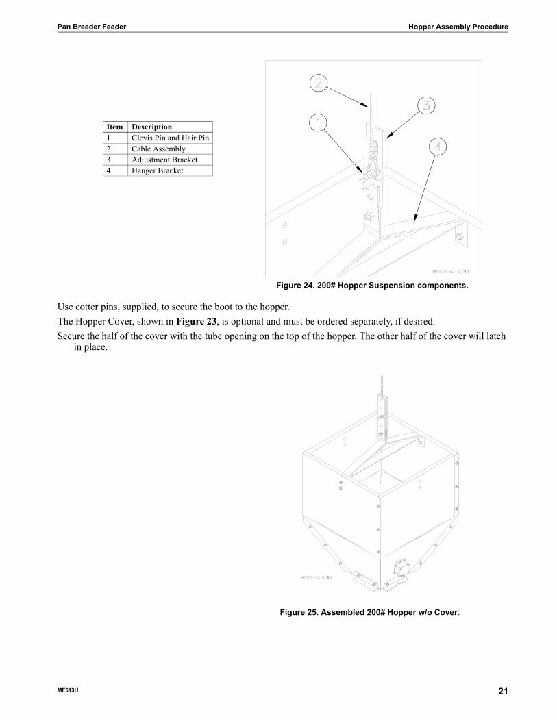
suspend the hopper. Figure 24 shows the suspension components assembled. The pin should be located in the center hole of the Hanger.
Install the Hopper Switch, as shown in Figure 23.Figure 25 shows the assembled hopper with suspension components installed.Suspend the hopper, as shown in Figure 3 page 10 by routing the cable around the Full Line Suspension Pulley
and fastened to the main cable, using (2) cable clamps.To install the boot on the hopper, slide the boot onto the hangers built into the bottom of the hopper.
Hopper Assembly Procedure
Item Description1 Hopper Cover (stationary half)2 Hopper Cover (removable)3 Hair Pin4 Adjustment Bracket5 Clevis Pin6 Hanger Bracket7 Side Panel (w/Hole)8 Lower Hopper Level Switch9 Deflector10 Diaphragm11 Boot Hanger12 Side Panel (w/o Hole)13 Tube Support Kit
Figure 23. 200# Hopper Assembly Procedure
20 MF513H
Pan Breeder Feeder Hopper Assembly Procedure
Use cotter pins, supplied, to secure the boot to the hopper.The Hopper Cover, shown in Figure 23, is optional and must be ordered separately, if desired. Secure the half of the cover with the tube opening on the top of the hopper. The other half of the cover will latch
in place.
Figure 24. 200# Hopper Suspension components.
Item Description1 Clevis Pin and Hair Pin2 Cable Assembly3 Adjustment Bracket4 Hanger Bracket
Figure 25. Assembled 200# Hopper w/o Cover.
MF513H 21
Feeder Assembly Procedure Pan Breeder Feeder
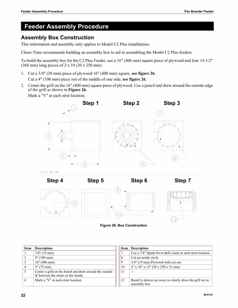
Assembly Box ConstructionThis information and assembly only applies to Model C2 Plus installations.
Chore-Time recommends building an assembly box to aid in assembling the Model C2 Plus feeders.
To build the assembly box for the C2 Plus Feeder, use a 16" (406 mm) square piece of plywood and four 14-1/2" (368 mm) long pieces of 2 x 10 (20 x 250 mm).
1. Cut a 3/4" (20 mm) piece of plywood 16" (400 mm) square, see figure 26.Cut a 4" (100 mm) piece out of the middle of one side, see figure 26.
2. Center the grill on the 16" (400 mm) square piece of plywood. Use a pencil and draw around the outside edge of the grill as shown in Figure 26. Mark a "V" at each strut location.
Feeder Assembly Procedure
Item Description Item Description1 3/4" (19 mm) 7 Use a 7/8" Spade bit to drill a hole at each strut location.2 4" (100 mm) 8 Cut on inside circle3 16" (406 mm) 9 3/4" (19 mm) Plywood with cut-out4 3" (75 mm) 10 2" x 10" x 13" (50 x 250 x 33 mm)5 Center a grill on the board and draw around the outside
& between the struts on the inside.11 --
6 Mark a "V" at each strut location 12 Board is shown cut away to clearly show the grill set in assembly box.
Figure 26. Box Construction
Step 1 Step 2 Step 3
Step 4 Step 5 Step 6 Step 7
22 MF513H

Pan Breeder Feeder Feeder Assembly Procedure
3. Remove the grill.Use a 7/8" (22 mm) spade bit to drill a hole at each strut location, as shown in Figure 26.
4. Use a sabre saw to cut along the inside circle, between the 7/8" holes, see figure 26.5. Use (4) 14-1/2" (370 mm) 2 x 10’s (50 x 250 mm) to construct the box sides, see figure 26.
It is important to use at least 10" (250 mm) sides for the box. Smaller lumber will not allow sufficient depth for the grill to be placed in the box face down.
6. Nail the 3/4" plywood fixture to the box, see figure 26.Figure 26 shows how the grill should fit down in assembly box. NOTE: Board is cut away for clarity only.
Pan Assembly Procedure1. Place a Grill in the pan assembly box fixture. Make sure the hinge lip on the grill is located in the cut out
section of the box.2. Two-Piece Model C2 Plus Feeders: Install the Cone Adjustment and Support Cone in the grill, as shown in
Figure 27.One-Piece Model C2 Plus Feeders: Install the One-Piece Support Cone in the grill, as shown in Figure 27.
Figure 27. Model C2 Plus Feeder Assembly3. Interlock the hinge hook on the pan with the hinge lip on the grill. The pan should be face up, as shown in
Figure 28.Flip the pan into the groove of the grill.
4. With the feeder still in the fixture, rotate the pan clockwise in the grill until pan locks engage.The tabs (on the bottom of the pan) may be used to grip the pan when rotating.
5. Remove the pan assembly from the fixture.6. Build all the required Feeder Assemblies for the house.
Model C2 Pluswith windows
Grill
Adjustment Cone
Support Cone
Restrictor Tube
Feeder Pan
Model C2 PlusNon-Window
Grill
Support ConeNon-Window
Restrictor Tube
Pan
Rotate the pan to lockgrill ring.
MF513H 23

Feeder Line Assembly & Suspension Pan Breeder Feeder
The Feeder Assemblies will be installed on the auger tubes in the Feeder Line Installation section.
Figure 28. C2 Pan Assembly
Feeder Pan and Tube Assembly Process1. Slide one Feeder Pan Assembly per hole onto the Auger Tubes.
IMPORTANT: Install all the feeders on the tubes in the same orientation. When sliding the feeders on the tubes, make sure the grill openings or hinges are on the same side of the tube.
2. Rotate the auger tubes so that the seam is down, this holds the Pan Assemblies in place on the tubes, see figure 29.
Assemble and Suspend the Feeder Line
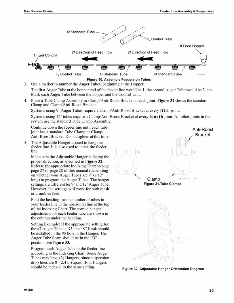
Figure 29. Assemble Feeders on Tubes1. The auger tubes and feeders may be laid out end to end in approximately the final location of the line. The
expanded end of each tube should be toward the Hopper end of the line, see figure 30.2. Connect the individual feeder tubes together by inserting the straight end of one tube as far as possible into
the belled end of the next tube.Use suspension drop lines and Hangers to support the tubes as they are being installed. Make sure the tubes are level.
Feeder Line Assembly & Suspension
Key Description1 Model C2 Plus Pan2 Hinge Hook3 Hinge Lip4 Support Cone
1255-82 1/2001
1) With the Hem of the Feeder Tube up slide theFeeder Pan Assembly on the Feeder Tube.
Position one (1) Feeder Pan Assembly over eachhole on the Feeder Tube.
3) Rotate the Feeder Tube after theFeeder Pan Assemblies arein place. This will lock the
Feeder Pan Assemblies in place
2) Feeder Tube4) Feeder Pan Assembly
24 MF513H
Pan Breeder Feeder Feeder Line Assembly & Suspension
Figure 30. Assemble Feeders on Tubes3. Use a marker to number the Auger Tubes, beginning at the Hopper.
The first Auger Tube at the hopper end of the feeder line would be 1, the second Auger Tube would be 2, etc. Mark each Auger Tube between the hopper and the Control Unit.
4. Place a Tube Clamp Assembly or Clamp/Anti-Roost Bracket at each joint. Figure 31 shows the standard Clamp and Clamp/Anti-Roost Bracket.Systems using 9’ Auger Tubes require a Clamp/Anti-Roost Bracket at every f i f th joint. Systems using 12’ tubes require a Clamp/Anti-Roost Bracket at every fourth joint. All other joints in the system use the standard Tube Clamp Assembly.Continue down the feeder line until each tube joint has a standard Tube Clamp or Clamp/Anti-Roost Bracket. Do not tighten at this time.
5. The Adjustable Hanger is used to hang the feeder line. It is also used to index the feeder line.Make sure the Adjustable Hanger is facing the proper direction, as specified in Figure 32. Refer to the appropriate Indexing Chart on page page 27 or page 28 of this manual (depending on whether your Auger Tubes are 9’ or 12’ long) to program the Auger Tubes. The hanger settings are different for 9’ and 12’ Auger Tube. However, the settings will work for both mash or crumbles feed.Find the heading for the number of tubes in your feeder line in the horizontal line at the top of the Indexing Chart. The correct hanger adjustments for each feeder tube are shown in the column under the heading.Setting Example: If the appropriate setting for the #7 Auger Tube is D5, the “S” Hook should be installed in the #5 hole in the Hanger. The Auger Tube Seam should be in the “D” position, see figure 33.Program each Auger Tube in the feeder line according to the Indexing Chart. Some Auger Tubes may have (2) Hangers, since suspension drop lines are 8’ (2.4 m) apart. Both Hangers should be indexed to the same setting.
2) Direction of Feed Flow
3) Feed Hopper
1) End Control2) Direction of Feed Flow
4) Standard Tube
5) Control Tube
1255-123 3/20015) Control Tube 4) Standard Tube 4) Standard Tube
Clamp
Anti-Roost Bracket
Figure 31.Tube Clamps
Figure 32. Adjustable Hanger Orientation Diagram
MF513H 25
Feeder Line Assembly & Suspension Pan Breeder Feeder
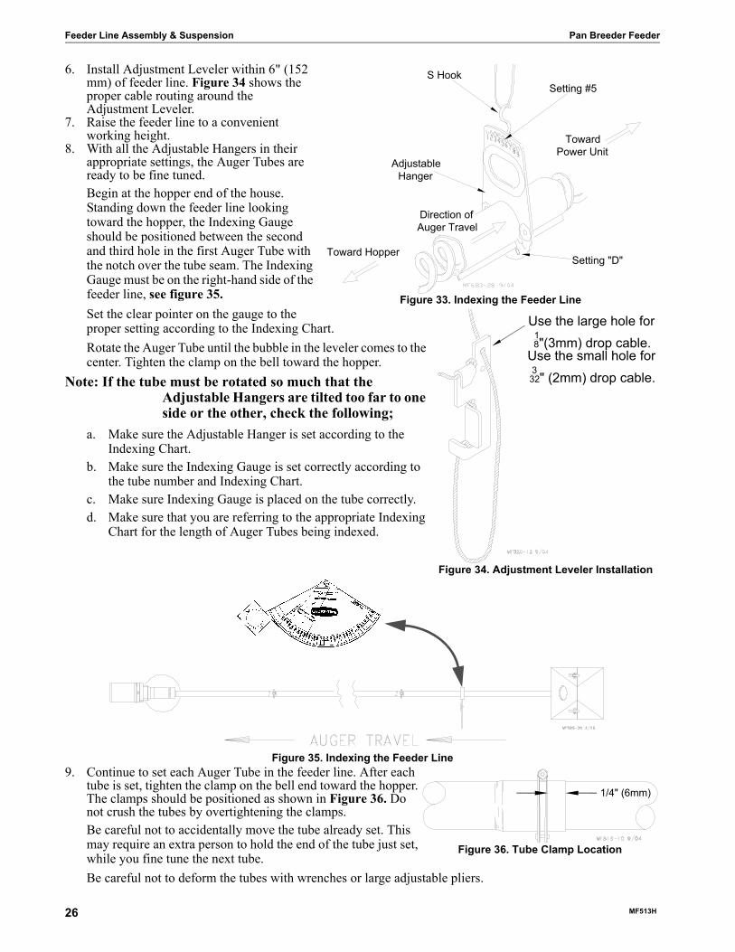
6. Install Adjustment Leveler within 6" (152 mm) of feeder line. Figure 34 shows the proper cable routing around the Adjustment Leveler.
7. Raise the feeder line to a convenient working height.
8. With all the Adjustable Hangers in their appropriate settings, the Auger Tubes are ready to be fine tuned.Begin at the hopper end of the house. Standing down the feeder line looking toward the hopper, the Indexing Gauge should be positioned between the second and third hole in the first Auger Tube with the notch over the tube seam. The Indexing Gauge must be on the right-hand side of the feeder line, see figure 35.Set the clear pointer on the gauge to the proper setting according to the Indexing Chart. Rotate the Auger Tube until the bubble in the leveler comes to the center. Tighten the clamp on the bell toward the hopper.
Note: If the tube must be rotated so much that the Adjustable Hangers are tilted too far to one side or the other, check the following;
a. Make sure the Adjustable Hanger is set according to the Indexing Chart.
b. Make sure the Indexing Gauge is set correctly according to the tube number and Indexing Chart.
c. Make sure Indexing Gauge is placed on the tube correctly.d. Make sure that you are referring to the appropriate Indexing
Chart for the length of Auger Tubes being indexed.
Figure 35. Indexing the Feeder Line9. Continue to set each Auger Tube in the feeder line. After each
tube is set, tighten the clamp on the bell end toward the hopper. The clamps should be positioned as shown in Figure 36. Do not crush the tubes by overtightening the clamps.Be careful not to accidentally move the tube already set. This may require an extra person to hold the end of the tube just set, while you fine tune the next tube. Be careful not to deform the tubes with wrenches or large adjustable pliers.
Direction of Auger Travel
Setting "D"
Toward Power Unit
Toward Hopper
Adjustable Hanger
S HookSetting #5
Figure 33. Indexing the Feeder Line
Use the large hole for 18"(3mm) drop cable.
Use the small hole for 332" (2mm) drop cable.
Figure 34. Adjustment Leveler Installation
1/4" (6mm)
Figure 36. Tube Clamp Location
26 MF513H

Pan Breeder Feeder Feeder Line Assembly & Suspension
Indexing Chart for Pan Breeder FeedersFor Systems using 9’ (2.7 m) Auger Tube and 696 RPM Power Units
Number of Tubes31 30 29 28 27 26 25 24 23 22 21 20 19 18 17 16
1 B5 B5 B6 B6 B6 B6 B6 B7 B7 B7 B8 B8 B8 B9 B9 B9 12 B6 B6 B7 B7 B7 B7 B7 B8 B8 B8 B9 B9 B9 C1 C1 C1 23 B7 B7 B8 B8 B8 B8 B8 B9 B9 B9 C1 C1 C1 C1 C1 C2 34 B8 B8 B9 B9 B9 B9 B9 C1 C1 C1 C1 C1 C1 C2 C2 C3 45 B9 B9 C1 C1 C1 C1 C1 C1 C1 C1 C2 C2 C2 C2 C3 C4 56 C1 C1 C1 C1 C1 C1 C1 C2 C2 C2 C2 C2 C2 C3 C4 C5 67 C1 C1 C2 C2 C2 C2 C2 C2 C2 C2 C3 C3 C3 C4 C5 C6 78 C2 C2 C2 C2 C2 C2 C2 C3 C3 C3 C4 C4 C4 C5 C6 C7 89 C2 C2 C3 C3 C3 C3 C3 C4 C4 C4 C5 C5 C5 C6 C7 C8 910 C3 C3 C3 C3 C4 C4 C4 C4 C4 C5 C6 C6 C6 C7 C8 D2 1011 C3 C3 C4 C4 C4 C4 C5 C5 C5 C6 C7 C7 C7 C8 D2 D4 1112 C4 C4 C4 C4 C5 C5 C5 C6 C6 C7 C7 C8 C8 D2 D4 D6 1213 C4 C4 C5 C5 C5 C5 C6 C7 C7 C7 C8 C8 D2 D4 D6 D7 1314 C5 C5 C5 C5 C6 C6 C7 C7 C7 C8 C8 D2 D4 D6 D7 D8 1415 C5 C5 C6 C6 C7 C7 C7 C8 C8 C8 D2 D4 D6 D7 D8 E3 1516 C6 C6 C6 C7 C7 C7 C8 C8 C7 D2 D4 D6 D7 D8 E3 E5 1617 C6 C6 C7 C7 C8 C8 C8 D1 D2 D4 D6 D7 D8 E3 E5 1718 C7 C7 C7 C8 C8 C8 D1 D2 D4 D6 D7 D8 E3 E5 1819 C7 C7 C8 C8 D1 D1 D2 D4 D6 D7 D8 E3 E5 1920 C8 C8 C8 D1 D2 D2 D4 D6 D7 D8 E3 E5 2021 C8 C8 D1 D2 D3 D4 D6 D7 D8 E3 E5 2122 D1 D1 D2 D3 D4 D6 D7 D8 E3 E5 2223 D2 D2 D3 D4 D6 D8 D8 E3 E5 2324 D3 D3 D4 D6 D8 D9 E3 E5 2425 D4 D4 D6 D8 D9 E3 E5 2526 D5 D6 D8 D9 E3 E5 2627 D6 D8 D9 E3 E5 2728 D8 D9 E3 E5 2829 D9 E3 E5 2930 E3 E5 3031 E5 31
Tube
Num
ber
MF513H 27

Feeder Line Assembly & Suspension Pan Breeder Feeder
For Systems using 12’ (3.6 m) Auger Tube and 696 RPM Power Units
Number of Tubes31 30 29 28 27 26 25 24 23 22 21 20 19 18 17 16
1 B5 B5 B5 B5 B6 B6 B6 B6 B6 B7 B7 B7 B7 B8 B8 B8 12 B6 B6 B6 B6 B7 B7 B7 B7 B7 B8 B8 B8 B8 B9 B9 B9 23 B7 B7 B7 B7 B8 B8 B8 B8 B8 B9 B9 B9 B9 C1 C1 C1 34 B8 B8 B8 B8 B9 B9 B9 B9 B9 C1 C1 C1 C1 C2 C2 C2 45 B9 B9 B9 B9 C1 C1 C1 C1 C1 C1 C2 C2 C2 C2 C3 C3 56 C1 C1 C1 C1 C1 C1 C1 C2 C2 C2 C2 C2 C2 C3 C4 C4 67 C1 C1 C2 C2 C2 C2 C2 C2 C2 C2 C3 C3 C3 C4 C5 C6 78 C2 C2 C2 C2 C2 C2 C2 C3 C3 C3 C4 C4 C4 C5 C6 C7 89 C2 C2 C3 C3 C3 C3 C3 C4 C4 C4 C5 C5 C5 C6 C7 C8 910 C3 C3 C3 C3 C4 C4 C4 C4 C4 C5 C6 C6 C6 C7 C8 D2 1011 C3 C3 C4 C4 C4 C4 C5 C5 C5 C6 C7 C7 C7 C8 D2 D5 1112 C4 C4 C4 C4 C5 C5 C5 C6 C6 C7 C7 C8 C8 D2 D5 D6 1213 C4 C4 C5 C5 C5 C5 C6 C7 C7 C7 C8 C8 D2 D4 D6 D7 1314 C5 C5 C5 C5 C6 C6 C7 C7 C7 C8 C8 D2 D4 D6 D7 D8 1415 C5 C5 C6 C6 C7 C7 C7 C8 C8 C8 D2 D4 D6 D7 D8 E3 1516 C6 C6 C6 C7 C7 C7 C8 C8 C7 D2 D4 D6 D7 D8 E3 E5 1617 C6 C6 C7 C7 C8 C8 C8 D1 D2 D4 D6 D7 D8 E3 E5 1718 C7 C7 C7 C8 C8 C8 D1 D2 D4 D6 D7 D8 E3 E5 1819 C7 C7 C8 C8 D1 D1 D2 D4 D6 D7 D8 E3 E5 1920 C8 C8 C8 D1 D2 D2 D4 D6 D7 D8 E3 E5 2021 C8 C8 D1 D2 D3 D4 D6 D7 D8 E3 E5 2122 D1 D1 D2 D3 D4 D6 D7 D8 E3 E5 2223 D2 D2 D3 D4 D6 D8 D8 E3 E5 2324 D3 D3 D4 D6 D8 D9 E3 E5 2425 D4 D4 D6 D8 D9 E3 E5 2526 D5 D6 D8 D9 E3 E5 2627 D6 D8 D9 E3 E5 2728 D8 D9 E3 E5 2829 D9 E3 E5 2930 E3 E5 3031 E5 31
Tube
Num
ber
28 MF513H
Pan Breeder Feeder Feeder Line Assembly & Suspension
Indexing the Male Feeder1. Beginning at the hopper, use a marker to number the feeder tubes. Begin with tube #1 at the hopper, then #2,
#3, and do on, continuing until each tube in the line is marked.2. Loosen the tube clamps, or if a new house, leave the tube clamps loose, until the line has been indexed.3. Use the Proper Indexing Chart for the tube that is being indexed. The indexing starts are based on the tube
length.Find the heading for the number of tubes in your system in the horizontal line at the top of the indexing chart. The correct hanger adjustments for each feeder tube are shown in the column under the heading.
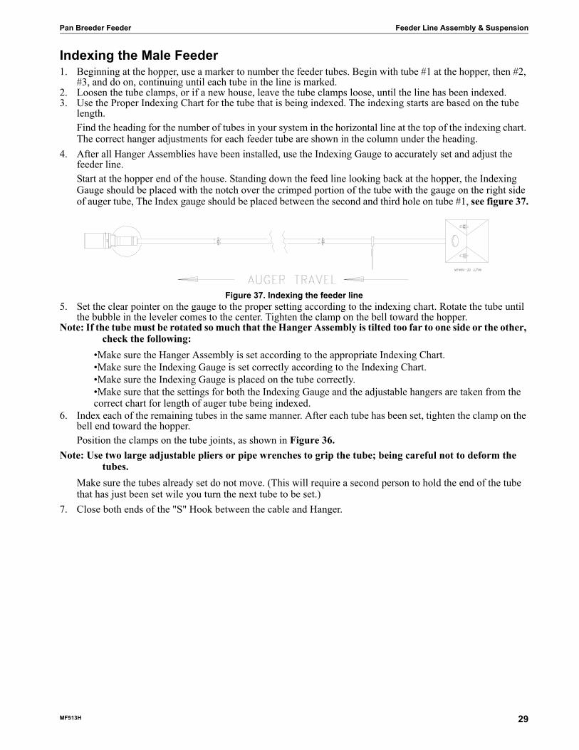
4. After all Hanger Assemblies have been installed, use the Indexing Gauge to accurately set and adjust the feeder line.Start at the hopper end of the house. Standing down the feed line looking back at the hopper, the Indexing Gauge should be placed with the notch over the crimped portion of the tube with the gauge on the right side of auger tube, The Index gauge should be placed between the second and third hole on tube #1, see figure 37.
Figure 37. Indexing the feeder line5. Set the clear pointer on the gauge to the proper setting according to the indexing chart. Rotate the tube until
the bubble in the leveler comes to the center. Tighten the clamp on the bell toward the hopper.Note: If the tube must be rotated so much that the Hanger Assembly is tilted too far to one side or the other,
check the following:•Make sure the Hanger Assembly is set according to the appropriate Indexing Chart.•Make sure the Indexing Gauge is set correctly according to the Indexing Chart.•Make sure the Indexing Gauge is placed on the tube correctly.•Make sure that the settings for both the Indexing Gauge and the adjustable hangers are taken from the correct chart for length of auger tube being indexed.
6. Index each of the remaining tubes in the same manner. After each tube has been set, tighten the clamp on the bell end toward the hopper.Position the clamps on the tube joints, as shown in Figure 36.
Note: Use two large adjustable pliers or pipe wrenches to grip the tube; being careful not to deform the tubes.
Make sure the tubes already set do not move. (This will require a second person to hold the end of the tube that has just been set wile you turn the next tube to be set.)
7. Close both ends of the "S" Hook between the cable and Hanger.
MF513H 29

Feeder Line Assembly & Suspension Pan Breeder Feeder
Indexing Chart for Male FeedersFor Systems using 9’ (2.7 m) Auger Tube and 348 RPM Power Units
Number of Tubes31 30 29 28 27 26 25 24 23 22 21 20 19 18 17 16
1 B4 B4 B4 B4 B4 B5 B5 B5 B5 B6 B6 B6 B7 B7 B7 B7 12 B5 B5 B5 B5 B5 B6 B6 B6 B6 B7 B7 B7 B8 B8 B8 B8 23 B6 B6 B6 B6 B6 B7 B7 B7 B7 B8 B8 B8 B9 B9 B9 B9 34 B7 B7 B7 B7 B7 B8 B8 B8 B8 B9 B9 B9 C1 C1 C1 C1 45 B8 B8 B8 B8 B8 B9 B9 B9 B9 C1 C1 C1 C2 C2 C2 C3 56 B8 B9 B9 B9 B9 C1 C1 C1 C1 C2 C2 C2 C3 C3 C3 C5 67 B9 B9 C1 C1 C1 C2 C2 C2 C2 C3 C3 C3 C4 C4 C5 C6 78 B9 C1 C1 C1 C2 C2 C3 C3 C3 C4 C4 C4 C4 C5 C6 C7 89 C1 C1 C2 C2 C2 C3 C3 C3 C4 C4 C4 C4 C5 C6 C7 C8 910 C1 C2 C2 C2 C3 C3 C4 C4 C4 C5 C5 C5 C6 C7 C8 D1 1011 C2 C2 C3 C3 C3 C4 C4 C4 C5 C5 C5 C6 C7 C8 D1 D2 1112 C2 C3 C3 C3 C4 C4 C5 C5 C5 C6 C6 C7 C8 D1 D2 D3 1213 C3 C3 C4 C4 C4 C5 C5 C5 C6 C6 C7 C8 D1 D2 D3 D5 1314 C3 C4 C4 C4 C5 C5 C6 C6 C6 C7 C8 D1 D2 D3 D5 D7 1415 C4 C4 C5 C5 C5 C6 C6 C6 C7 C8 D1 D2 D3 D5 D7 E2 1516 C4 C5 C5 C6 C6 C6 C7 C7 C7 D1 D2 D3 D5 D7 E2 E3 1617 C5 C5 C6 C6 C6 C7 C7 C8 C8 D2 D3 D5 D7 E2 E3 1718 C5 C6 C6 C7 C7 C7 C8 D1 D1 D3 D5 D7 E2 E3 1819 C6 C6 C7 C7 C7 C8 D1 D2 D2 D5 D7 E2 E3 1920 C6 C7 C7 C8 C8 D1 D2 D3 D5 D7 E2 E3 2021 C7 C7 C8 C8 D1 D2 D3 D5 D7 E2 E3 2122 C7 C8 C8 D1 D2 D3 D5 D7 E2 E3 2223 C8 C8 D1 D2 D3 D5 D7 E2 E3 2324 C8 D1 D2 D3 D5 D7 E2 E3 2425 D1 D2 D3 D5 D7 E2 E3 2526 D2 D3 D5 D7 E2 E3 2627 D3 D5 D7 E2 E3 2728 D5 D7 E2 E3 2829 D7 E2 E3 2930 E2 E3 3031 E3 31
Tube
Num
ber
30 MF513H

Pan Breeder Feeder Feeder Line Assembly & Suspension
For Systems using 12’ (3.6m) Auger Tube and 696 RPM Power Units
Number of Tubes31 30 29 28 27 26 25 24 23 22 21 20 19 18 17 16
1 B5 B5 B5 B6 B6 B6 B7 B7 B7 B8 B8 B8 B8 B9 B9 B9 12 B6 B6 B6 B7 B7 B7 B8 B8 B8 B9 B9 B9 B9 C1 C1 C1 23 B7 B7 B7 B8 B8 B8 B9 B9 B9 C1 C1 C1 C1 C2 C2 C2 34 B7 B8 B8 B9 B9 B9 C1 C1 C1 C2 C2 C2 C2 C3 C3 C3 45 B8 B8 B9 B9 C1 C1 C1 C1 C2 C2 C2 C3 C3 C4 C4 C4 56 B8 B9 B9 C1 C1 C1 C2 C2 C2 C3 C3 C3 C4 C4 C5 C5 67 B9 B9 C1 C1 C2 C2 C2 C2 C3 C3 C3 C4 C4 C5 C5 C6 78 B9 C1 C1 C2 C2 C2 C3 C3 C3 C4 C4 C4 C5 C5 C6 C7 89 C1 C1 C2 C2 C3 C3 C3 C3 C4 C4 C4 C5 C5 C6 C7 C8 910 C1 C2 C2 C3 C3 C3 C4 C4 C4 C5 C5 C5 C6 C7 C8 D1 1011 C2 C2 C3 C3 C4 C4 C4 C4 C5 C5 C5 C6 C7 C8 D1 D2 1112 C2 C3 C3 C4 C4 C4 C5 C5 C5 C6 C6 C7 C8 D1 D2 D3 1213 C3 C3 C4 C4 C5 C5 C5 C5 C6 C6 C7 C8 D1 D2 D3 D5 1314 C3 C4 C4 C5 C5 C5 C6 C6 C6 C7 C8 D1 D2 D3 D5 D7 1415 C4 C4 C5 C5 C6 C6 C6 C6 C7 C8 D1 D2 D3 D5 D7 E2 1516 C4 C5 C5 C6 C6 C6 C7 C7 C7 D1 D2 D3 D5 D7 E2 E3 1617 C5 C5 C6 C6 C7 C7 C7 C8 C8 D2 D3 D5 D7 E2 E3 1718 C5 C6 C6 C7 C7 C7 C8 D1 D1 D3 D5 D7 E2 E3 1819 C6 C6 C7 C7 C8 C8 D1 D2 D2 D5 D7 E2 E3 1920 C6 C7 C7 C8 C8 D1 D2 D3 D5 D7 E2 E3 2021 C7 C7 C8 C8 D1 D2 D3 D5 D7 E2 E3 2122 C7 C8 C8 D1 D2 D3 D5 D7 E2 E3 2223 C8 C8 D1 D2 D3 D5 D7 E2 E3 2324 C8 D1 D2 D3 D5 D7 E2 E3 2425 D1 D2 D3 D5 D7 E2 E3 2526 D2 D3 D5 D7 E2 E3 2627 D3 D5 D7 E2 E3 2728 D5 D7 E2 E3 2829 D7 E2 E3 2930 E2 E3 3031 E3 31
Tube
Num
ber
MF513H 31

Feeder Line Assembly & Suspension Pan Breeder Feeder
Model C2 Plus Feeder Lock InstallationThe Model C2 Plus Feeder Lock is designed for pullet operations to prevent the feeders from swinging on the auger tubes.
Note: The seam of auger tube and hardware for the Lock must be on opposite sides as shown. Otherwise an interference will occur.
Install the friction pad on the tube (remove oil from tube where the pad will be installed) where the anti swing clamp will be installed.
To install, gently spread the Lock to allow it to slide over the auger tube as shown in Figure 38.
Slide the Lock into position against the Feeder Support Cone.
Make sure the feeder is in the upright position before securing the Lock to the auger tube using the hardware supplied.
Figure 38. Feeder Lock installation
Figure 39. Feeder Anti-Swing Clamp Installation
Friction PadUnder Feeder Lock
32 MF513H
Pan Breeder Feeder
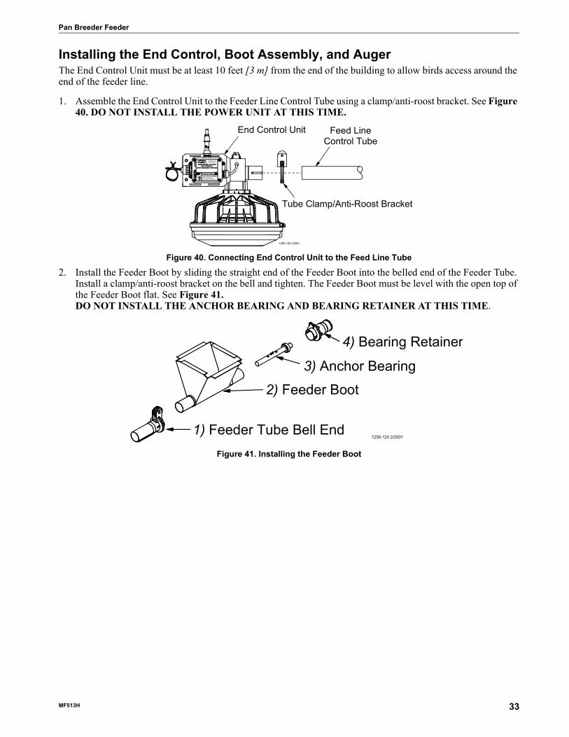
Installing the End Control, Boot Assembly, and AugerThe End Control Unit must be at least 10 feet [3 m] from the end of the building to allow birds access around the end of the feeder line.
1. Assemble the End Control Unit to the Feeder Line Control Tube using a clamp/anti-roost bracket. See Figure 40. DO NOT INSTALL THE POWER UNIT AT THIS TIME.
Figure 40. Connecting End Control Unit to the Feed Line Tube
2. Install the Feeder Boot by sliding the straight end of the Feeder Boot into the belled end of the Feeder Tube. Install a clamp/anti-roost bracket on the bell and tighten. The Feeder Boot must be level with the open top of the Feeder Boot flat. See Figure 41.DO NOT INSTALL THE ANCHOR BEARING AND BEARING RETAINER AT THIS TIME.
Figure 41. Installing the Feeder Boot
2529-710
42680 MODEL C2 PLUSEND CONTROL
WITH PROXIMITY SWITCH
CHORE-TIME EQUIPMENTA DIVISION OF CTB INC.
MILFORD, INDIANA 46542-2000
Do not open this controlbox until electrical power isdisconnected at circuit breakers.
ELECTROCUTION HAZARD!
DANGER
End Control Unit Feed LineControl Tube
Tube Clamp/Anti-Roost Bracket
1255-125 4/2001
1) Feeder Tube Bell End
2) Feeder Boot3) Anchor Bearing
4) Bearing Retainer
1255-120 2/2001
MF513H 33

Pan Breeder Feeder
Auger InstallationNote: Use extreme caution when working with the auger. The auger is under tension and may spring
causing personal injury. Wear protective clothing, gloves, and safety glasses when working with the auger.
To avoid kinking the auger, be careful not to drop the rolled auger when handling. Inspect the auger carefully as it is installed. Small kinks may be straightened. Large kinks must be removed and the auger brazed back together.
Cut the leading 18" [450 mm] and last 18" [450 mm] off each roll of auger. Also, cut out any other distorted auger sections and reconnect the auger as specified in the Auger Brazing section of this manual..
1. Use extreme caution when pushing the auger into the auger tubes. Keep your hand away form the end of the auger tube to avoid injury.With the auger coiled about 6 feet [1.8 m] from the end of the boot, uncoil the auger from the outside and feed the auger through the boot into the tubes.Push the auger into the tube in short strokes.Uncoil and handle the auger carefully to avoid damaging or kinking the auger.
2. If more that one coil is required for each feeder line, the auger ends will have to be brazed together. Refer to the Brazing the Auger section in this manual.
3. Install the Anchor Bracket to the Power Unit/Gearhead, as shown in Figure 42, with the included5/16-18 Bolts.
Manboot 3/98
BE CAREFUL WHEN WORKING WITH THE
AUGER!
KEEP HANDS AWAY FROM PINCH POINTS WHEN INSTALLING
AUGER.
CAUTION
1255-124 4/2001
1) Power Unit/Gearhead
3) Anchor Bracket
2) 5/16-18 Bolts
Figure 42. Assemble the Anchor Bracket to the Power Unit/Gearhead
34 MF513H

Pan Breeder Feeder
4. Slide the Drive Tube and flat washer over the output shaft on the Power Unit, as shown in Figure 43.5. Continue installing auger until the auger reaches the Control Unit end of the feeder line.6. Turn the Drive Tube Weldment into the auger, then attach to the output shaft of the Power Unit, as shown in
Figure 43. Use the Driver Block to secure the auger to the Output Shaft.
7. Attach the Anchor Plate and Gearhead Assembly to the Control Unit Body using the included 1/4'' Lock Washers and 1/4-20 x 1/2'' Bolts, see figure 44.Figure 44.
1255-93 4/2001
2) Drive Tube Weldment
1) Driver Block
3) Control Unit not shown for clarity
4) 1/4-20 x 1-1/2" Socket Head Bolt
6) Auger
Figure 43. Auger Driver Components
Anchor Plate andGearhead Assembly
Control Unit Body
Switch Box CoverSwitch Box Gasket
1255-126 4/2001
1/4-20 x 1/2" Bolt1/4" Lock Washer
Figure 44. Attaching the Anchor Plate and Gearhead Assembly to the Control Unit Body
MF513H 35

Pan Breeder Feeder
8. Install the Metal Water Tight Connector (item 1) in the Feed Line Motor (item 2). Cut the Flex Conduit (item 3) to length. Slide the wires from the end control through the Flex Conduit (item 3). Install the Flex Conduit (item 3) in the connectors. Connect the wires to the Feed Line Motor (item 2).
Wiring the Motor
9. Attach all covers and wire according to the wiring section of this manual.10. Pull the auger at the boot end until it begins stretching. Then let it relax. In the relaxed position, mark the
auger at the end of the boot. See Figure 45.
Figure 45. Measure the Auger from the relaxed position
11. Auger stretch:The auger needs to be stretched 7" [180 mm] per 100’ [30 m]. Example: A 300’ [90 m] feeder line requires 21" [500 mm] of stretch.Beginning at the relaxed position, measure the required amount of stretch. Mark the auger at that point. Grip the auger 8" [200 mm] ahead of this mark with locking pliers. Allow the auger to pull back into the boot so that the pliers rest against the end of the boot. See Figure 46.
2529-710
42680 MODEL C2 PLUSEND CONTROL
WITH PROXIMITY SWITCH
CHORE-TIME EQUIPMENTA DIVISION OF CTB INC.
MILFORD, INDIANA 46542-2000
Do not open this controlbox until electrical power isdisconnected at circuit breakers.
ELECTROCUTION HAZARD!
DANGER
1 2 3 4
10
11
5 6
9
1634-08 4/2000
7
8
1255-94 9/2000
1) Mark the relaxed augerat the end of the boot
36 MF513H

Pan Breeder Feeder
Use a hacksaw or bolt cutters to cut the auger at the stretched auger mark.
Figure 46. Cut the Auger with required stretch
12. Insert the Anchor Assembly into the auger until it touches the washer at the back of the anchor. Tighten the setscrews in the center of the anchor until they touch the auger, then tighten a maximum of 1/2 turn. See Figure 47.
DO NOT OVERTIGHTEN THE SET SCREWS.
Figure 47. Auger and Anchor Bearing Connection13. Carefully remove the locking pliers while holding onto the Anchor and Bearing Assembly and auger
securely.Slowly ease the auger back into the tube. Use caution. If the auger is allowed to spring back, the bearing race may crack.Install the Bearing Retainer and fasten with a tube clamp. Keep the Bearing Retainer flush with the end of the anchor for safety.
14. Place the cannonball in the boot.
1255-95 9/2000
1) Locking Pliers2) Use a hacksaw or boltcutters to cut the auger
3) Pull an extra 8" [200 mm] of auger (minimum)to allow for Anchor and Bearing Installation
4) Boot under Feed Hopper
KEEP HANDS AWAY FROM PINCH POINTS WHEN INSTALLING
AUGER.
CAUTION
Set Screws
Auger Alignment Pins
Manboot 3/98
BE CAREFUL WHEN WORKING WITH THE
AUGER!
MF513H 37

Pan Breeder Feeder
Auger BrazingThe auger should be brazed if it is necessary to splice or lengthen it. A bronze, flux coated rod is recommended.
The ends of the auger should butt against each other, DO NOT THREAD INSIDE EACH OTHER. See Figure 48.Figure 48. The joint should be well filled with no sharp edges or rough corners to wear against the tube. To align the auger for brazing, lay it in angle or channel iron and clamp it firmly in place. Use low heat. Allow the joint to air cool; rapid cooling will cause the auger to become brittle.
Figure 48. Auger Brazing
1255-97 9/2000
1) Braze here
1) Braze here
2) Lap the auger endsapproximately 1" [25 mm]
3) Butt the auger ends togetherDO NOT thread the auger together
38 MF513H

Pan Breeder Feeder
Anti-Roost Installation1. Unroll the bulk anti-roost cable. Note: If the cable is unrolled as
shown in Figure 49, taking 5 loops of the coil with one hand, then changing hands to remove 5 loops as it is unrolled, it will lie flat during installation.
2. Start at the hopper end of the line and form a loop around the anti-roost bracket. For best results, make a double loop around the anti-roost insulator in the center groove of the insulator and fasten with a 1/16" cable clamp as shown in Figure 50.
3. Insert the cable in the insulator on the top of each Grill Support between the hopper and the next anti-roost bracket.
4. Attach a spring in the center groove at the second anti-roost bracket and cut the cable at this point. See Figure 51.
5. Thread the ends of the cable through the end of the spring. Pull the cable tight so that there is 3/4" to 1" [20 to 25 mm] of stretch in the spring. Clamp the cable to form a loop and cut off any excess. See Figure 51.
6. Attach the cable to the insulator. For best results, make a double loop around the anti-roost insulator in the center groove of the insulator and fasten with a 1/16" cable clamp as shown in Figure 51.
7. Run the cable to the next insulator, attach a spring in the center groove at the anti-roost bracket and cut the cable at this point. The cable should be positioned in the insulator built into the top of each grill support along the feeder line.
8. Repeat this installation until the anti-roost cable is installed along the entire feeder line.9. At the control unit, after clamping the cable to the spring, cut the cable about 8" to 10" [200 to 250 mm]
longer than necessary. Feed the end of the cable through the center of the spring, around the first insulator on the control unit, and clamp the cable using the cable clamp supplied with the control unit. See Figure 52.
10. Install the wire form on the control unit insulators. Be sure the guard snaps into the retainers molded into the insulators. See Figure 52.
Shock2 3/98
Figure 49. Unrolling the Cable
1255-102 9/2000
2) Clamp with InsulatorBracket and Insulator
1) Cable Clamp
3) Anti-Roost Cable
Figure 50. Anti-Roost Cable at the Hopper
1255-103 9/2000
1) Cable Clamp4) Spring should be stretched3/4" to 1" [19 mm to 25 mm]
3) Anti-Roost Cable
1) Cable Clamp2) Clamp with InsulatorBracket and Insulator
Figure 51. Anti-Roost Cable Intermediate Connection
MF513H 39
Pan Breeder Feeder
Figure 52. Anti-Roost Installation at the Control Unit
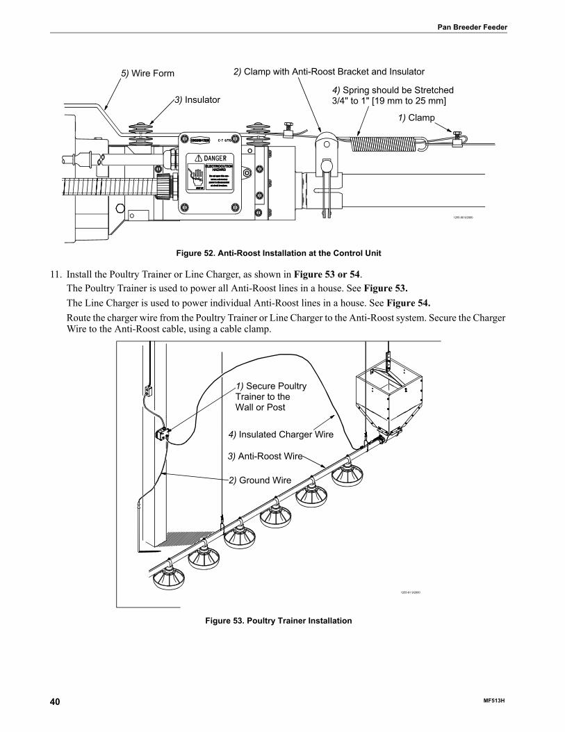
11. Install the Poultry Trainer or Line Charger, as shown in Figure 53 or 54.The Poultry Trainer is used to power all Anti-Roost lines in a house. See Figure 53.The Line Charger is used to power individual Anti-Roost lines in a house. See Figure 54.Route the charger wire from the Poultry Trainer or Line Charger to the Anti-Roost system. Secure the Charger Wire to the Anti-Roost cable, using a cable clamp.
Figure 53. Poultry Trainer Installation
1255-90 9/2000
1) Clamp
2) Clamp with Anti-Roost Bracket and Insulator5) Wire Form
3) Insulator4) Spring should be Stretched3/4" to 1" [19 mm to 25 mm]
1255-91 9/2000
1) Secure PoultryTrainer to theWall or Post
2) Ground Wire
3) Anti-Roost Wire
4) Insulated Charger Wire
40 MF513H

Pan Breeder Feeder
Figure 54. Line Charger Installation
12. The anti-roost system must be on a separate electrical circuit, allowing the system to be disconnected by a switch near the door.Remember, the anti-roost system should be grounded through the poultry trainer.
1255-92 9/2000
1) Line Charger
2) Insulated Charger Wire
3) Anti-Roost Wire
MF513H 41
Feeder Management Pan Breeder Feeder
42 MF513H
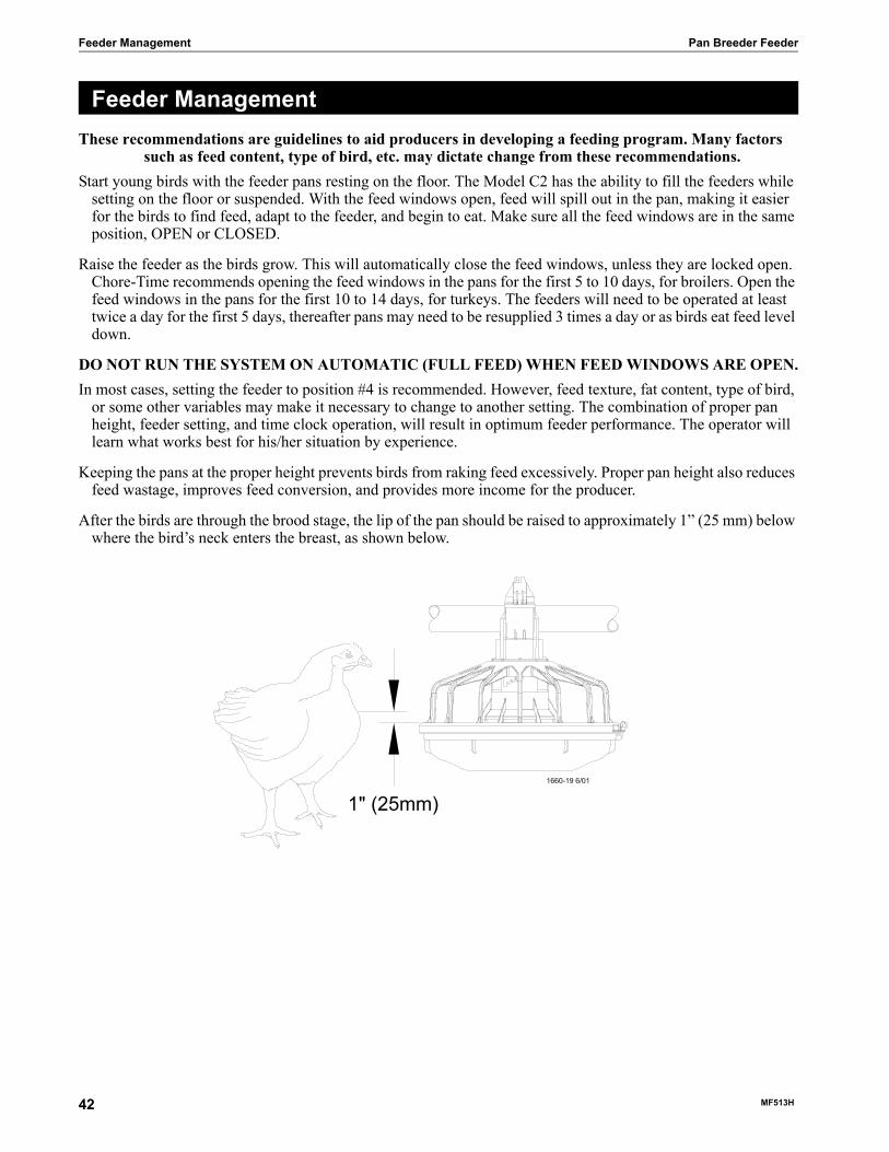
These recommendations are guidelines to aid producers in developing a feeding program. Many factors such as feed content, type of bird, etc. may dictate change from these recommendations.
Start young birds with the feeder pans resting on the floor. The Model C2 has the ability to fill the feeders while setting on the floor or suspended. With the feed windows open, feed will spill out in the pan, making it easier for the birds to find feed, adapt to the feeder, and begin to eat. Make sure all the feed windows are in the same position, OPEN or CLOSED.
Raise the feeder as the birds grow. This will automatically close the feed windows, unless they are locked open. Chore-Time recommends opening the feed windows in the pans for the first 5 to 10 days, for broilers. Open the feed windows in the pans for the first 10 to 14 days, for turkeys. The feeders will need to be operated at least twice a day for the first 5 days, thereafter pans may need to be resupplied 3 times a day or as birds eat feed level down.
DO NOT RUN THE SYSTEM ON AUTOMATIC (FULL FEED) WHEN FEED WINDOWS ARE OPEN.In most cases, setting the feeder to position #4 is recommended. However, feed texture, fat content, type of bird,
or some other variables may make it necessary to change to another setting. The combination of proper pan height, feeder setting, and time clock operation, will result in optimum feeder performance. The operator will learn what works best for his/her situation by experience.
Keeping the pans at the proper height prevents birds from raking feed excessively. Proper pan height also reduces feed wastage, improves feed conversion, and provides more income for the producer.
After the birds are through the brood stage, the lip of the pan should be raised to approximately 1” (25 mm) below where the bird’s neck enters the breast, as shown below.
Feeder Management
1" (25mm)
Pan Breeder Feeder Maintenance
Floor Feeding System MaintenanceThe Model C2 Plus and Model G Plus Feeders require minimum maintenance. However, a routine periodic inspection of the equipment will prevent unnecessary problems.
Maintenance should be done by a qualified technician.
ALWAYS DISCONNECT POWER TO THE SYSTEM WHEN SERVICING OR MAINTAINING THE EQUIPMENT. FAILURE TO DISCONNECT POWER MAY CAUSE INJURY OR DEATH.
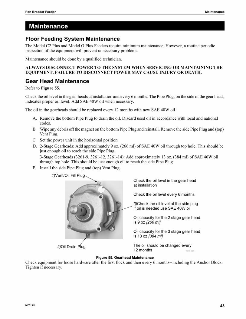
Gear Head MaintenanceRefer to Figure 55.
Check the oil level in the gear heads at installation and every 6 months. The Pipe Plug, on the side of the gear head, indicates proper oil level. Add SAE 40W oil when necessary.
The oil in the gearheads should be replaced every 12 months with new SAE 40W oil
A. Remove the bottom Pipe Plug to drain the oil. Discard used oil in accordance with local and national codes.
B. Wipe any debris off the magnet on the bottom Pipe Plug and reinstall. Remove the side Pipe Plug and (top) Vent Plug.
C. Set the power unit in the horizontal position.D. 2-Stage Gearheads: Add approximately 9 oz. (266 ml) of SAE 40W oil through top hole. This should be
just enough oil to reach the side Pipe Plug.3-Stage Gearheads (3261-9, 3261-12, 3261-14): Add approximately 13 oz. (384 ml) of SAE 40W oil through top hole. This should be just enough oil to reach the side Pipe Plug.
E. Install the side Pipe Plug and (top) Vent Plug.
Figure 55. Gearhead MaintenanceCheck equipment for loose hardware after the first flock and then every 6 months--including the Anchor Block. Tighten if necessary.
Maintenance
1)Vent/Oil Fill Plug
2)Oil Drain Plug
Check the oil level in the gear headat installation
Check the oil level every 6 months
3)Check the oil level at the side plugIf oil is needed use SAE 40W oil
Oil capacity for the 2 stage gear headis 9 oz [266 ml]
Oil capacity for the 3 stage gear headis 13 oz [384 ml]
The oil should be changed every12 months 1660-22 1/2001
MF513H 43
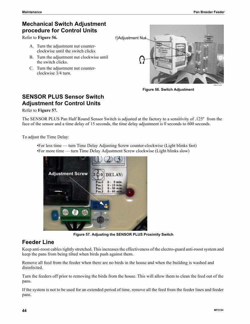
Maintenance Pan Breeder Feeder
Mechanical Switch Adjustment procedure for Control UnitsRefer to Figure 56.
A. Turn the adjustment nut counter-clockwise until the switch clicks.
B. Turn the adjustment nut clockwise until the switch clicks.
C. Turn the adjustment nut counter-clockwise 3/4 turn.
SENSOR PLUS Sensor Switch Adjustment for Control UnitsRefer to Figure 57.
The SENSOR PLUS Pan Half Round Sensor Switch is adjusted at the factory to a sensitivity of .125'' from the face of the sensor and a time delay of 15 seconds, the time delay adjustment is 0 seconds to 600 seconds.
To adjust the Time Delay:
•For less time — turn Time Delay Adjusting Screw counter-clockwise (Light blinks fast)•For more time — turn Time Delay Adjustment Screw clockwise (Light blinks slow)
Figure 57. Adjusting the SENSOR PLUS Proximity Switch
Feeder LineKeep anti-roost cables tightly stretched. This increases the effectiveness of the electro-guard anti-roost system and keep the pans from being tilted when birds push against them.
Remove all feed from the feeder when there are no birds in the house and when the building is washed and disinfected.
Turn the feeders off prior to removing the birds from the house. This will allow them to clean the feed out of the pans.
If the system is not to be used for an extended period of time, remove all the feed from the feeder lines and feeder pans.
1)Adjustment Nut
1660-23 1/2001
Figure 56. Switch Adjustment
Adjustment Screw
44 MF513H

Pan Breeder Feeder Maintenance
Disconnect power to the system to prevent accidentally starting the system.
If the system must be disassembled, extreme caution must be used to prevent injury from springing auger. Refer to Figure 58.
1. Disconnect power to the entire system.2. Loosen the Tube Clamp on the bearing at the hopper end of the
system. Remove the Tube Clamp and Bearing Retainer.3. Pull the Anchor and Bearing Assembly and approximately
18'' [45 cm] of auger out of the boot.CAUTION: Stand clear...the auger may spring back into the
tube.4. Place a clamp or locking plier securely on the auger to prevent it from springing back into the auger boot.5. Loosen the setscrew in the bearing assembly shaft and remove the Anchor and Bearing Assembly from the
auger.
To reinstall the Anchor and Bearing Assembly:1. Insert the Anchor Assembly into the auger, guide the
tip of the auger between the two roll pins in the center of the anchor. Continue to guide the auger until the tip of the auger hits the flat washer. Tighten the setscrews in the center of the anchor until they touch the auger. See Figure 58.
2. Carefully remove the locking pliers while holding onto the Anchor and Bearing Assembly and auger securely.Slowly ease the auger back into the tube. Use caution. If the auger is allowed to spring back, the bearing race may crack.Install the Bearing Retainer and fasten with a tube clamp. Keep the Bearing Retainer flush with the end of the anchor for safety.
Power Lift Winch MaintenanceRefer to Figure 59.
Grease the winch every 6 months with 1 to 2 shots of common industrial or automotive grease.DO NOT OVER GREASE THE WINCH.
Remove any feed build-up in the Safety Switch Boxes in the Control Units.
It may be necessary to periodically retighten the shocker cable. Be sure to disconnect power to the shocker before servicing the equipment.
Figure 58. Auger and Anchor Bearing Connection
Low head socket head screw
Roll pins
Flat washer
1)Grease the Power Lift Winch every 6 months with 1to 2 shots of common industrial or automotive greaseDO NOT OVER GREASE THE POWER LIFT WINCH
1660-24 6/2001
Figure 59. Maintenance to the Power Lift Winch
MF513H 45

Trouble Shooting the Floor Feeding System Pan Breeder Feeder
ALWAYS DISCONNECT POWER TO THE SYSTEM WHEN SERVICING OR MAINTAINING THE EQUIPMENT. FAILURE TO DISCONNECT POWER MAY CAUSE INJURY OR DEATH.
Service and maintenance work should be done by a qualified technician only.
Trouble Shooting the Floor Feeding System
Problem Possible Cause Corrective ActionNone of the feeder lines will operate No power supplied to equipment Replace burned fuses or reset circuit breaker
Make sure voltage required is suppliedTime Clock or relay defective Replace Time Clock or relayTime Clock improperly programmed
Refer to Programming the Time Clock section and reprogram the Time Clock
Feeder line will not operate Power unit cord not plugged in sufficiently to make contact
Check motor cord plug at control unit and control unit plug at outlet for connection
Motor cord wires are broken at plug or where cord enters motor
Check cord for continuityReplace if defective
Power Units thermal overload tripped
Push motor overload reset button to reset
Control unit switch defective or out of adjustment
Adjust switch according to the Switch Adjustment Procedure in the maintenance section
Motor overloads frequently Oil on new auger loads motor excessively when feed is carried for first time
Polish auger by running 50 lb (20 kg) increments of feed out to pans
Inadequate power reaching motors Check line voltage at the motorsCheck starting current draw at motorsWiring of adequate size is essential to feeder operation
Object caught in the auger; motor runs, stalls, then auger spins in reverse
Check hopper boot, control unit and pan outlet holes for foreign objectsRemove obstruction
Auger runs erratically Frozen or cracked bearing at boot anchor
Replace bearingSlowly ease auger back into tubeBe careful not to damage the bearing when reinserting the auger
Insufficient stretch in auger Shorten the augerObstruction in the auger Remove obstruction
Auger tube or boot wears out rapidly(Noisy feeder operation)
Auger is bent or kinked Repair or replace damaged augerEnd of auger is riding up on anchor weldment
Auger must not be positioned over weld on anchorCheck for bent or damaged auger
Oil leaking out of seals on power unit Gearhead vent plug not installed Replace plastic shipping plug with vent plugDefective gear head seal Replace seal
Not enough feed supplied to the feeder pans
Insufficient time programmed on the time clock
Add more operating time to feeding period
Feeder line control unit switch out of adjustment
Adjust switch according to the Switch Adjustment Procedure in the maintenance section
46 MF513H

Pan Breeder Feeder Wiring Diagrams
Winch Control Wiring Diagram with 29820-3 Tower Limit Switch37215 MULTI-LIFT Winch with 34812 Winch Control
and 29820-3 Tower Limit Switchor
14560 or 14580 Electric Power Winch with 34812 Winch Controland 29820-3 Tower Limit Switch
Winch Control Wiring Diagram with 39464 Limit Switch37215 MULTI-LIFT with 34812 Winch Control and 39464 Limit Switch
Wiring Diagrams
MF513H 47

Wiring Diagrams Pan Breeder Feeder
Male Feeder System Wiring Diagrams: Single Phase(Ø)Single Phase(Ø) Wiring Diagram
Single Phase(Ø) Wiring Diagram: w/Motor Starter
48 MF513H

Pan Breeder Feeder Wiring Diagrams
Male Feeder System Wiring Diagrams: Three Phase(Ø)Three Phase(Ø) Wiring Diagram: 220/230 V
Three Phase(Ø) Wiring Diagram: 380/415 V
MF513H 49

Wiring Diagrams Pan Breeder Feeder
Electric Power Lift Wiring Diagram
50 MF513H

Pan Breeder Feeder Parts Listing
Standard Breeder Pans
Parts Listing
44362
39567C2 Plus Grill
44354Non-window cone
41501Feeder Pan
41893Reduction Tube
44351Support Cone
41501Feeder Pan
38604Adjustment Cone
44299Packed Cones
39567C2 Plus Grill
41893Reduction Tube
DEPBRED1.fh5tjc 01/02/01
44348
38603Removable Top
44353Non-window cone
41501Feeder Pan
41893Reduction Tube
44352Support Cone
41501Feeder Pan
38604Adjustment Cone
44346Packed Cones
39567C2 Plus Grill
41893Reduction Tube
STANDARD BREEDER PANNON-WINDOW, & REDUCTIONTUBE
44361 STANDARD BREEDER PANW/WINDOWS, & REDUCTIONTUBE
STANDARD BREEDER PANNON-WINDOW, REDUCTIONTUBE & REM. TOP
44347STANDARD BREEDER PANW/WINDOWS, REDUCTION TUBE, &REM. TOP
39567C2 Plus Grill
38603Removable Top
MF513H 51
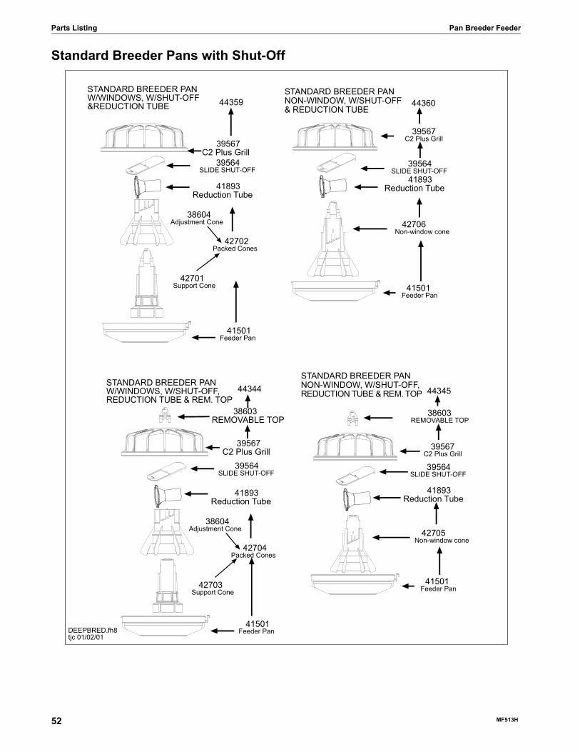
Parts Listing Pan Breeder Feeder
Standard Breeder Pans with Shut-Off
DEEPBRED.fh8tjc 01/02/01
44359
39567C2 Plus Grill
42701Support Cone
41501Feeder Pan
44360
39567C2 Plus Grill
42706Non-window cone
41501Feeder Pan
STANDARD BREEDER PANW/WINDOWS, W/SHUT-OFF&REDUCTION TUBE
38604Adjustment Cone
STANDARD BREEDER PANNON-WINDOW, W/SHUT-OFF& REDUCTION TUBE
42702Packed Cones
39564SLIDE SHUT-OFF
39564SLIDE SHUT-OFF
41893Reduction Tube 41893
Reduction Tube
44344
39567C2 Plus Grill
42703Support Cone
41501Feeder Pan
44345
39567C2 Plus Grill
42705Non-window cone
41501Feeder Pan
STANDARD BREEDER PANW/WINDOWS, W/SHUT-OFF,REDUCTION TUBE & REM. TOP
38604Adjustment Cone
STANDARD BREEDER PANNON-WINDOW, W/SHUT-OFF,REDUCTION TUBE & REM. TOP
42704Packed Cones
39564SLIDE SHUT-OFF
39564SLIDE SHUT-OFF
41893Reduction Tube
41893Reduction Tube
38603REMOVABLE TOP
38603REMOVABLE TOP
52 MF513H
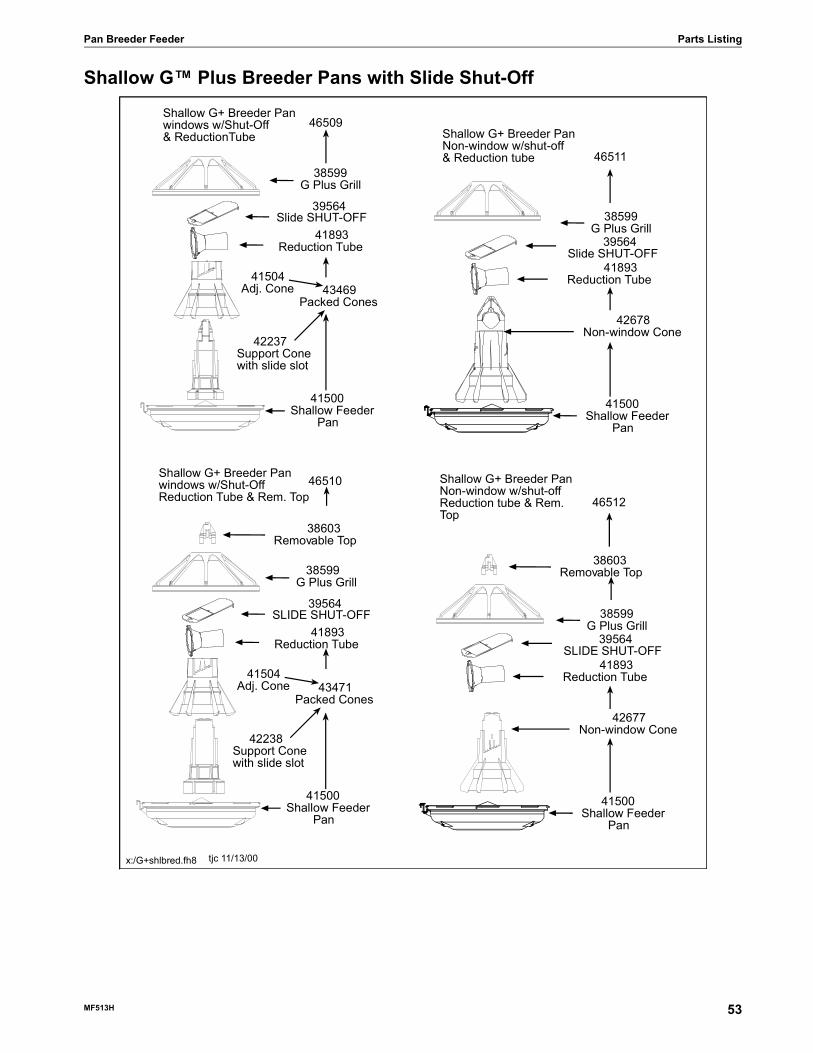
Pan Breeder Feeder Parts Listing
Shallow G™ Plus Breeder Pans with Slide Shut-Off
Shallow G+ Breeder Panwindows w/Shut-Off& ReductionTube
46509
38599G Plus Grill
41504Adj. Cone
42237Support Conewith slide slot
41500Shallow Feeder Pan
43469Packed Cones
46511
38599G Plus Grill
41500Shallow Feeder Pan
42678Non-window Cone
Shallow G+ Breeder PanNon-window w/shut-off& Reduction tube
tjc 11/13/00
Slide SHUT-OFF39564
x:/G+shlbred.fh8
Slide SHUT-OFF39564 41893
Reduction Tube
41893Reduction Tube
Shallow G+ Breeder Panwindows w/Shut-OffReduction Tube & Rem. Top
46510
38599G Plus Grill
41504Adj. Cone
42238Support Conewith slide slot
41500Shallow Feeder Pan
43471Packed Cones
46512
38599G Plus Grill
41500Shallow Feeder Pan
42677Non-window Cone
Shallow G+ Breeder PanNon-window w/shut-offReduction tube & Rem.Top
SLIDE SHUT-OFF39564
SLIDE SHUT-OFF39564 41893
Reduction Tube
41893Reduction Tube
38603Removable Top
38603Removable Top
MF513H 53
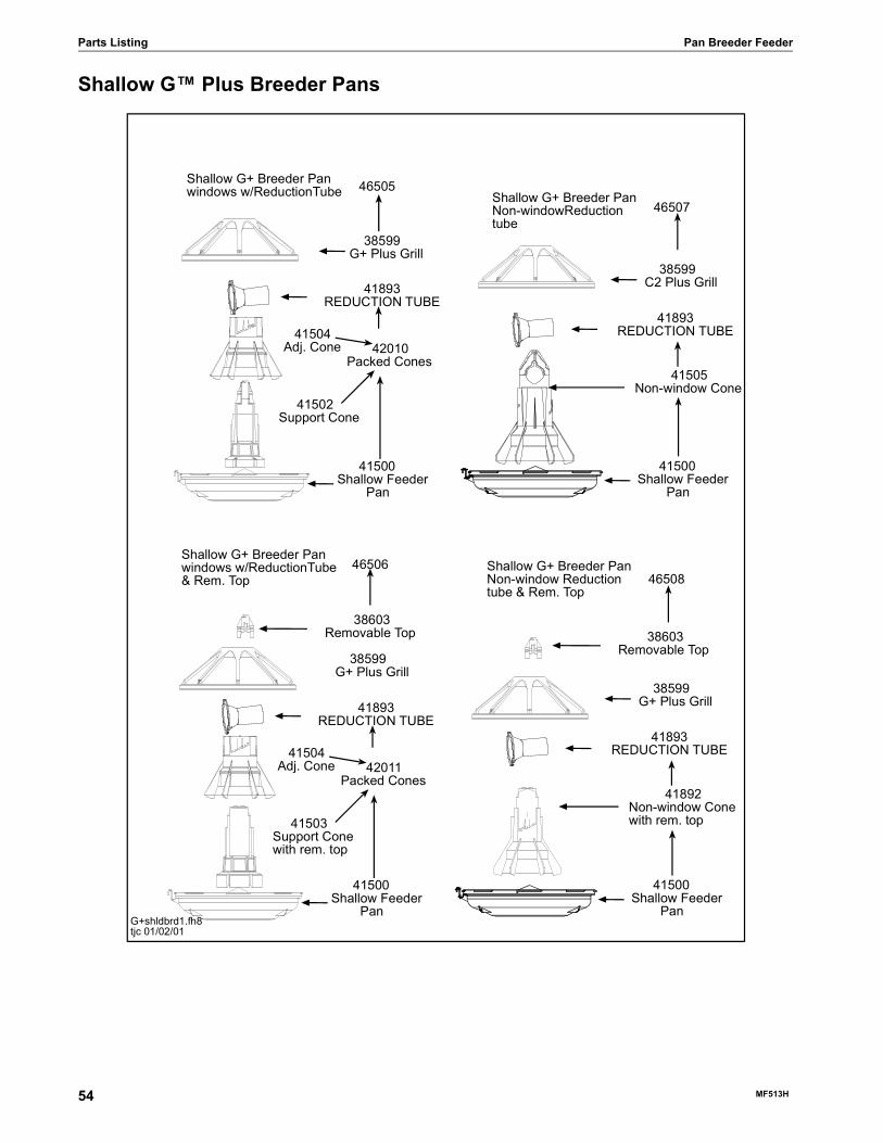
Parts Listing Pan Breeder Feeder
Shallow G™ Plus Breeder Pans
Shallow G+ Breeder Panwindows w/ReductionTube 46505
38599G+ Plus Grill
41504Adj. Cone
41502Support Cone
41500Shallow Feeder Pan
42010Packed Cones
41893REDUCTION TUBE
46507
38599C2 Plus Grill
41500Shallow Feeder Pan
41505Non-window Cone
Shallow G+ Breeder PanNon-windowReductiontube
41893REDUCTION TUBE
Shallow G+ Breeder Panwindows w/ReductionTube& Rem. Top
46506
38599G+ Plus Grill
41504Adj. Cone
41503Support Conewith rem. top
41500Shallow Feeder Pan
42011Packed Cones
41893REDUCTION TUBE
46508
38599G+ Plus Grill
41500Shallow Feeder Pan
41892Non-window Conewith rem. top
Shallow G+ Breeder PanNon-window Reductiontube & Rem. Top
41893REDUCTION TUBE
38603Removable Top 38603
Removable Top
G+shldbrd1.fh8tjc 01/02/01
54 MF513H

Pan Breeder Feeder Parts Listing
Shallow Breeder Pans
Shallow Breeder Panwindows w/ReductionTube 44357
39567C2 Plus Grill
41504Adj. Cone
41502Support Cone
41500Shallow Feeder Pan
42010Packed Cones
41893REDUCTION TUBE
44358
39567C2 Plus Grill
41500Shallow Feeder Pan
41505Non-window Cone
Shallow Breeder PanNon-windowReductiontube
41893REDUCTION TUBE
Shallow Breeder Panwindows w/ReductionTube& Rem. Top
44342
39567C2 Plus Grill
41504Adj. Cone
41503Support Conewith rem. top
41500Shallow Feeder Pan
42011Packed Cones
41893REDUCTION TUBE
44343
39567C2 Plus Grill
41500Shallow Feeder Pan
41892Non-window Conewith rem. top
Shallow Breeder PanNon-window Reductiontube & Rem. Top
41893REDUCTION TUBE
38603Removable Top 38603
Removable Top
shldbrd1.fh8tjc 11/10/99
MF513H 55

Parts Listing Pan Breeder Feeder
34812 Winch Control Parts Listing
14613 Switch Box Assembly
Item Description Part No. Item Description Part No.1 Switch Bracket 46846 11 Momentary Switch 57852 Toggle Switch (DPDT) 46847 12 Toggle Switch 60143 Clear Lid 30859-1 13 Pilot Light 70444 Control Box Latch 30862 14 Winch Control Panel 343825 Fuse Holder 24431 15 Time Clock 349126 Relay 5574 16 Track Mounting Socket 349097 4 PDT Relay (230 V) 34910 17 Terminal Strip 349258 Terminal Mount Bracket 34563 18 Control Box Latch Pivot 308639 Back Mount 34383 19 10 Amp Fuse 735010 Control Box Mount Panel 34852 20 Control Box 34985
Item Description Part No.1 Box 426102 Momentary Switch 57853 Toggle Switch 201354 Grounding Plate 146045 Toggle Switch Boot 17396 Push Button Boot 207847 Cover 40904
56 MF513H

Pan Breeder Feeder Parts Listing
8798 Switch Assembly
Item Description Part No.1 6-32 x 7/8" Rd. Hd. M.S. 19212 SPDT Actuator Switch 71143 Switch Insulation 1907-54 Switch Bracket 70685 #6 x 3/8" Slot Wash. Hd. Screw 67826 6-32 Hex Nut 7717 Pin 87578 Switch Box 78419 10-32 Hex Lock Nut 696310 Spring 697211 10-32 Hex Nut 429712 Mounting Plate 790813 #10 Twin Helix Screw 698014 Switch Box Cover 677615 Gasket 677716 Gasket 6968-117 Paddle 789618 Diaphragm Assembly 7900-- Deflector 28281
MF513H 57

Parts Listing Pan Breeder Feeder
Mechanical End Control
1660-14 2/2001
ELECTROCUTION HAZARD!
2529-660
END CONTROL40943 MODEL C2 PLUS
CHORE-TIME EQUIPMENTA DIVISION OF CTB INC.
MILFORD, INDIANA 46542-2000
DANGERDo not open this controlbox until electrical power isdisconnected at circuit breakers.
CONTACT RATINGS:1/2 H.P. @ 115 VAC1 H.P. @ 230 VAC
WITH WINDOW
25
24
23
22
21
29282726
36
37
35
303431
33
32
31 2 4 5
8
10
11
12 13 14
15
17 16
6
7
9
3031
20
18
19
58 MF513H

Pan Breeder Feeder Parts Listing
*These items are included in the Parts Package.
**Actuator Switch, Chore-Time part number 7114, is no longer available. When replacing, use 7114 Switch Replacement Kit Part Number 46678.
Item Description MODEL C2 Plus
Standard Part No.
40943
MODEL C2 Plus Shallow Part No.
42012
MODEL G Plus
Standard Part No.
40944
MODEL G Plus
Shallow Part No.
420281 Control Body 14434 14434 14434 144342 Deflector Panel 41363 41363 41363 413633 Paddle Retainer 25045 25045 25045 250454 Control Cover Assembly 24682 24682 24682 246825 Danger Decal 2527-9 2527-9 2527-9 2527-96 1/4-20x1-1/2 Socket Hd Screw 5083-8 5083-8 5083-8 5083-87 Driver Block 4642 4642 4642 46428 Drive Tube Weldment 44794 44794 44794 447949 Bottom Cover 14432 14432 14432 14432
10 Control Cord Assembly 25495 25495 25495 2549511 1/2” Liquid Tight Connector 24685 24685 24685 2468512 Switch Box 24702 24702 24702 2470213* Switch Bracket 46122 46122 46122 4612214* Switch Insulation 1907-5 1907-5 1907-5 1907-5
15** Actuator Switch 46091 46091 46091 4609116 1/2” Liquid Tight Connector 23810 23810 23810 2381017 14” Flexible Conduit 26982-1 26982-1 26982-1 26982-118 Straight Liquid Tight Connector 26980 26980 26980 2698019 Cut Sleeve 43110 43110 43110 4311020 Anchor Plate 4188 4188 4188 418821 Center Support Assembly 40947 37371 40947 3737122 Feeder Grill 39567 39567 38599 3859923 Mylar Assembly 25318 25318 25318 2531824 Feeder Pan 41501 41500 41501 4150025 Adjustment Cone 38604 41504 38604 4150426 Switch Box Cover 6776 6776 6776 677627 Switch Box Gasket 6777 6777 6777 677728 Danger/Product Identification Decal 2529-660 2529-697 2529-659 2529-69829 Support Bracket 24683 24683 24683 2468330 Spring 6972 6972 6972 697231 #10-32 Lock Nut 6963 6963 6963 696332 Paddle 46123 46123 46123 4612333 Gasket 6968-1 6968-1 6968-1 6968-134 Actuator Pin 8757 8757 8757 875735 Switch Box Mount 25084 25084 25084 2508436 Stop Panel 25433 25433 25433 2543337 Switch Bracket 40749 40749 40749 40749-- Anti-Roost Guard 2798 2798 2798 2798-- Parts Package 40809 40809 40809 40809
MF513H 59
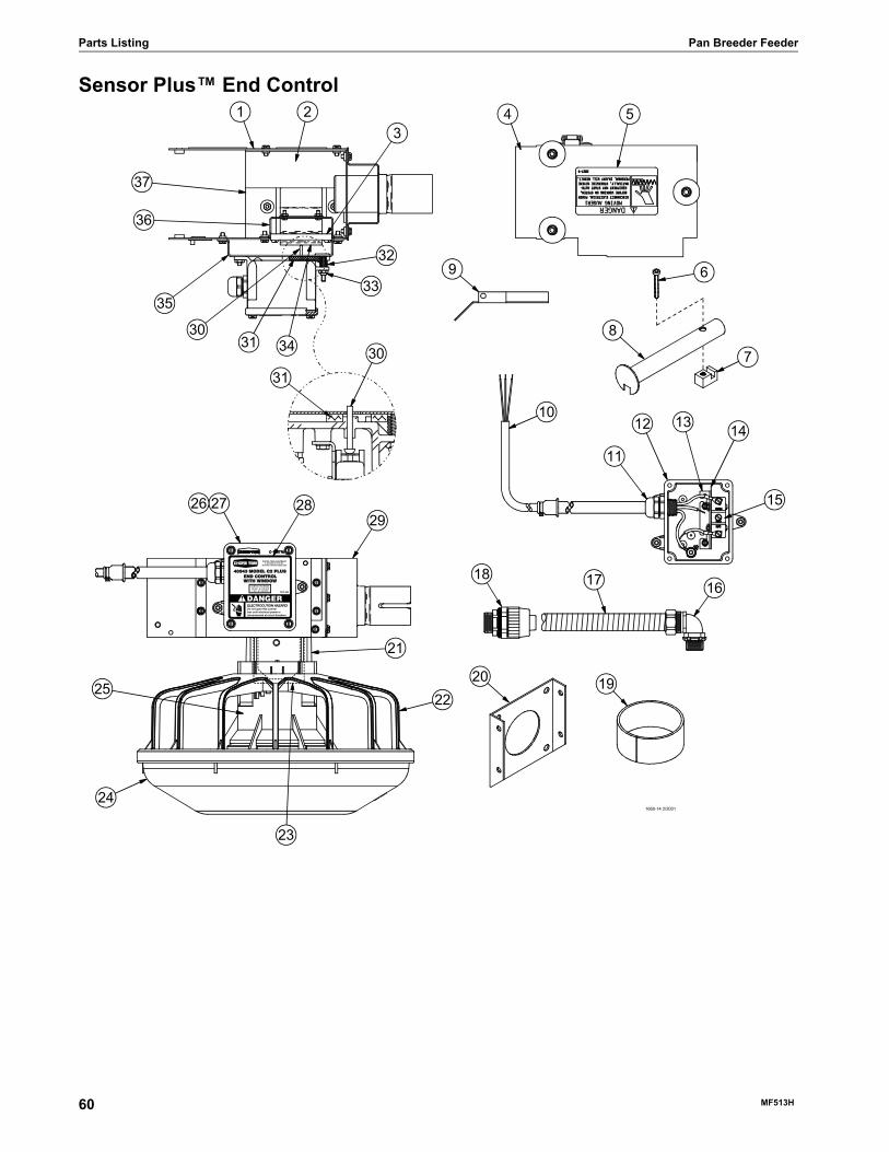
Parts Listing Pan Breeder Feeder
Sensor Plus™ End Control
1660-14 2/2001
ELECTROCUTION HAZARD!
2529-660
END CONTROL40943 MODEL C2 PLUS
CHORE-TIME EQUIPMENTA DIVISION OF CTB INC.
MILFORD, INDIANA 46542-2000
DANGERDo not open this controlbox until electrical power isdisconnected at circuit breakers.
CONTACT RATINGS:1/2 H.P. @ 115 VAC1 H.P. @ 230 VAC
WITH WINDOW
25
24
23
22
21
29282726
36
37
35
303431
33
32
31 2 4 5
8
10
11
12 13 14
15
17 16
6
7
9
3031
20
18
19
60 MF513H

Pan Breeder Feeder Parts Listing
Item Description C2 PlusStandardPart No.
42680
C2 Plus Shallow Part No.
44880
G PlusStandardPart No.
42597
G Plus Shallow Part No.
448821 Cut Sleeve 43110 43110 43110 431102 Bottom Cover 42085 42085 42085 420853 Top Cover with Insulators 42082 42082 42082 420824 Driver Block 4642 4642 4642 46425 Drive Tube Weldment 44794 44794 44794 447946 1/4-20x1-1/2 Socket Hd Screw 5083-8 5083-8 5083-8 5083-87 Tube Clamp 24063 24063 24063 240638 Support Bracket 42081 42081 42081 420819 Terminal Box Mounting Cover 6956 6956 6956 6956
10 Straight Liquid Tight Connector 26980 26980 26980 2698011 Switch Box Gasket 6777 6777 6777 677712 - - - - - - - - - - - - - - - - - - - -13 Danger/Product Identification Decal 2529-710 2529-731 2529-709 2529-72914 Cord Assembly 4999-100 4999-100 4999-100 4999-10015 Liquid Tight Connector 24685 24685 24685 2468516 - - - - - - - - - - - - - - - - - - - -17 Grill 39567 39567 38599 3859918 Adjustment Cone 38604 41504 38604 4150419 Feeder Pan 41501 41500 41501 4150020 #10 x 1/2 Hex Washer Head Screw 28075 28075 28075 2807521 General Purpose Terminal Box 42627-3 42627-3 42627-3 42627-322 Liquid Tight Connector 23779 23779 23779 2377923 Control Body Weldment 42080 42080 42080 4208024 Support Cone 37077 44884 37077 4488425 Pan Half Round Sensor 48200 48200 48200 4820026 14” Flexible Conduit 26982-1 26982-1 26982-1 26982-127 Liquid Tight Connector 23810 23810 23810 2381028 Anchor Plate 4188 4188 4188 4188
MF513H 61

Parts Listing Pan Breeder Feeder
Boot AssembliesSingle: Part No. 6822
Twin: Part No. 6824
*The Jumper Wire Kit includes an insulated piece of High-Voltage Wire (part no. 28994) and (2) cable clamps.
Item Description Part No.1 Boot Weldment (Single) 37602 Boot Weldment (Twin) 39323 Tube Clamp 240634 Cap 293735 Outlet Tube 45566 Sleeve 56487 3/16 x 1" Pin 2960-18 Bearing 26899 Washer 2955-1410 Anchor 3854011 Setscrew 4786712 Anchor and Bearing Ass’y 3937213 Cannonball 353114 Latch Pin Ass’y 2683--* Jumper Wire Kit 5960-- Danger Decal 2527-9
62 MF513H
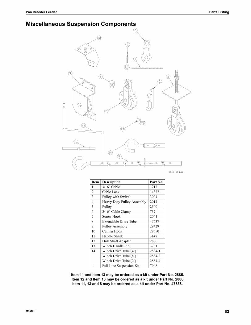
Pan Breeder Feeder Parts Listing
Miscellaneous Suspension Components
Item 11 and Item 13 may be ordered as a kit under Part No. 2885.Item 12 and Item 13 may be ordered as a kit under Part No. 2886Item 11, 13 and 8 may be ordered as a kit under Part No. 47638.
Item Description Part No.1 3/16" Cable 12132 Cable Lock 143373 Pulley with Swivel 30044 Heavy Duty Pulley Assembly 20145 Pulley 25006 3/16" Cable Clamp 7327 Screw Hook 20418 Extendable Drive Tube 476379 Pulley Assembly 2842910 Ceiling Hook 2855011 Handle Shank 314812 Drill Shaft Adapter 288613 Winch Handle Pin 376114 Winch Drive Tube (4’) 2884-1
Winch Drive Tube (8’) 2884-2Winch Drive Tube (2’) 2884-4
-- Full Line Suspension Kit 7948
MF513H 63

Parts Listing Pan Breeder Feeder
14580 Electric Winch Kit
The entire assembly, except item no. 14, may be ordered under part no. 14560 Electric Winch Kit
The entire assembly, except items no. 8 and 14, may be ordered under part no. 24508 Power Lift Parts Kit.
*See individual Parts List on page 66
Item Description Part No.1 5/16" Flat Washer 22302 5/16-18 Nut 21483 5/16-18 x 2-1/2" Hex Hd Bolt 27534 3/8-16 x 1" Hex Hd Bolt 25555 3/8" Flat Washer 49676 3/8" Patch Lock Nut 21837 Winch Mount Assembly 24580-- Caution Decal 2527-27-- Caution Decal 2527-298 Power Unit 3259-1459 5/16-18 x 3/4" Hex Hd Bolt 204610 Input Shaft Assembly 2780511 1/4-20 Socket Hd Cap Screw 5083-412 1/4-20 Locknut 126913 Power Unit Bracket 2788714 Power Winch 2883*15 Plastic Spacer 27833-- Switch Box Assembly 14613
64 MF513H

Pan Breeder Feeder Parts Listing
Feeder Line Components
* These parts may be ordered as a kit under part no. 14585.
Item Description Part No.1 Auger 6820wm2 Line Charger (110v) 5458
Line Charger (220v) 54593 Feeder Lock 345704 1/16" Cable 19225 1/16" Cable Clamp 18266 Spring 75517 Roll Formed Tube
12 Ft. 4 Hole Tube 6854-79 Ft. 4 Hole Tube 6854-1
8 Anti-Roost Bracket 240609 Tube Clamp 1-3/4" 2406310 Charger Wire (165’) 28994-165
Charger Wire (300’) 28994-33011 Hanger Assembly 760412 Grommet 1489913 Anti-Swing Bracket 1448514 Small "S" Hook 72315 3/16" Cable Clamp 121316 Friction Pad 4244317 Adjustment Clamp *352718 Tube Closure *9126
MF513H 65

Parts Listing Pan Breeder Feeder
2883 Power Winch
Indexing Gauge
Item Description Part No. Item Description Part No.1 Input Shaft Assembly
ManualElectric
4266542666
15 Drive Pinion 2962
2 Flange Bushing 2967-2 16 Woodruff Key 29593 Drive Stud 4128-1 17 1" Bearing 49374 Shoulder Bolt 4022-2 18 Spacer 49365 Pawl 6672 19 Retaining Ring 35566 5/16'' Flat Washer 2255-44 20 Washer 2955-27 Spring 1543 21 Winch Drum 37238 Spring Washer 4023 22 Drum Shaft 36379 Intermediate Gear 2890 23 Setscrew 60310 Flange Bushing 3252 24 Winch Frame 371911 Spirol Pin 2960-3 25 Setscrew 372712 Bushing 2967-4 26 Cable Hook 298513 Washer 2955-1 27 Grease Zerk 2449914 Retaining Ring 2958-1 28 Washer 2499
Item Description Part No.1 Level Glass 48532 Gauge Clamp Weldment 145233 Pointer Assembly 48524 Indexing Gauge Decal 2529-207
1660-25 2/2001
3
24
86
5
7
910
28
11
14
1312
24
2526
23
19
20
21
2715
16
1718
22
1
12 34
66 MF513H

Pan Breeder Feeder Parts Listing
Power Unit Assemblies
Item Description 3259-81 Part No.
3259-84 Part No.
3259-100 Part No.
3259-101 Part No.
3259-144 Part No.
1 Vent Plug 3516 3516 3516 3516 35162 5/16-18 x 5/8 Hex Hd Screw 4412-1 4412-1 4412-1 4412-1 4412-13 1/4-20 x 1-1/2 Socket Hd Screw 5083-8 5083-8 5083-8 5083-8 5083-84 Flat Washer 1484 1484 1484 1484 14845 Driver Block 4642 4642 4642 4642 46426 Gearhead 3261-11 3261-5 3261-11 3261-11 3261-177 Pipe Plug (magnetic) 30160 30160 30160 30160 301608 Pinion Assembly 5046 5046 5046 5046 50469 "S" Hook 2805 2805 2805 2805 280510 Motor 7522 4229 28031 28032EUR 5051
Part No. HP RPM Phase Hz Voltage Usages3259-81 3/4 HP 708 RPM Single Phase 50 Hz 230 9’ 4 & 12’ 4 Hole Auger Tubes3259-84 1/3 HP 348 RPM Single Phase 60 Hz 230 9’ 4 & 12’ 4 Hole Auger Tubes3259-100 1/2 HP 348 RPM Three Phase 50 Hz 220/380 9’ 1 & 9’ 2 Hole Auger Tubes3259-101 3/4 HP 696 RPM Three Phase 50 Hz 220/380 12’ 3 Hole Auger Tubes3259-144 3/4 HP 696 RPM Single Phase 60 Hz 230 9’ 4 & 12’ 4 Hole Auger Tubes
1660-21 1/2001
1
3 2
4
5 67
8
9
10
MF513H 67

Made to work.
Built to last.SM
Contact your nearby Chore-Time distributor or representative for additional parts and information.
CTB Inc.P.O. Box 2000 • Milford, Indiana 46542-2000 • U.S.A.
Phone (574) 658-4101 • Fax (877) 730-8825E-mail: [email protected] • Internet: http//www.choretime.com
Printed in the U.S.A.