Embed Size (px)
Citation preview

2/18© Dr. Dustin McLarty, 2017
» Land grant Institution founded in 1890» 29,686 Students (20,043 at Pullman Campus)
Set among the scenic Palouse hills

3/18© Dr. Dustin McLarty, 2017
How does pressurization affect performance?Are there alternative system configurations that enable pressurized operation?
How do we incorporate the slower transients of high temperature fuel cells with energy storage to meet local demands
What role can solid oxide technology and the hydrogen economy play in sustainable systems
Pressurized SOFC/SOEC
Micro-grid control
Food-Energy-Water Nexus

4/18© Dr. Dustin McLarty, 2017
» WSU’s test stand development˃ Testing challenges
» Why Pressurized SOFC/SOEC?˃ Higher FC operating voltage (also with pure O2 cathode)˃ Potential for low energy H2 recovery, in-situ methanation, ammonia co-
production, integrated carbon capture & liquefaction˃ Reduce/eliminate high temperature air heat exchangers (with pure O2
cathode)˃ Potential for continuous H2 production in both modes (integrate with H2
liquefier being developed at WSU)
» What will CESI lab test?˃ Pre-commercial SOFC cells (100mm X 100mm) at 0-145psig˃ Operation at elevated pressure with pure O2 cathode˃ Indirect/direct internal reforming˃ Participation of CO in electrochemistry˃ O2 purge cycle for closed-end cathode

5/18© Dr. Dustin McLarty, 2017
» 6kW furnace rated to 1000°C and 150psig˃ Top-hat style so top+ sides lift off to expose
working area˃ 12” I.D. test area

6/18© Dr. Dustin McLarty, 2017
Aerospace grade multi-sensor pass through
˃ Sensor diameter 0.1”˃ Pressure rating 150psig˃ Up to 28 sensors
Anode Heat Exchanger
Furnace Wall
Retu
rn
Retu
rnSu
pply
Return
Inconel Tubes
Bored-through fitting
» Concentric supply/return flows˃ Counter-flow heat
exchanger˃ Reduces holes in pressure
vessel
» Copper cored electrodes
» Shielded thermocouples
» Shielded voltage wire˃ Missile wire rated to
2000F

7/18© Dr. Dustin McLarty, 2017
» Cathode:˃ 150psig rated MFC for N2 delivering 0.210slpm
+ Expandable to 125slpm˃ 150psig rated MFC for O2/Air delivering 0.210slpm
» Anode˃ 150psig rated MFC for H2 delivering 0.15slpm˃ 150psig rated MFC for CO & CO2 delivering 0.0020.1slpm
» 1 kW Load bank˃ 200 amps˃ 10 voltage measurements
» Furnace Control» Humidifier Control» Humidifier
˃ Pressurized D-I water reservoir and liquid MFC for H2O delivering 0.210gpm
» Back pressure regulators˃ 3 X gas circuits, Anode, Cathode, Furnace, independent & linked
control˃ 3 X dual bottle 200 psig regulators with automatic switchover˃ 1 X 200 psig Argon regulator for inert furnace

8/18© Dr. Dustin McLarty, 2017
» Cathode plate A: raised channels with contact paste
» Cathode plate B: recessed channels with metallic foam for current collection
» Anode plate A: counter-flow, Nickel mesh current collector
» Anode Plate B: cross-flow, Nickel mesh current collector
» Bi-polar Plate = Cathode B + Anode B

9/18© Dr. Dustin McLarty, 2017
» Sealing˃ Thermal expansion mismatch between SS430
tray and YSZ electrolyte support˃ Bowing of anode supported cells at room
temperature breaks glass seal˃ Maintaining compression, initially up to
5MPa, due to tensioning rod creep during thermal cycling
+ Investigating Belleville washers (rated for 650°C)
» Pre-oxidizing SS430 trays˃ Settled on 3.5°C/min to 850°C with 5hr hold
» Leak testing˃ Added bypass that stops anode/cathode flow
and enables control of bypass pressure to measured anode/cathode pressure to avoid surge when bypass is closed.
10/18© Dr. Dustin McLarty, 2017
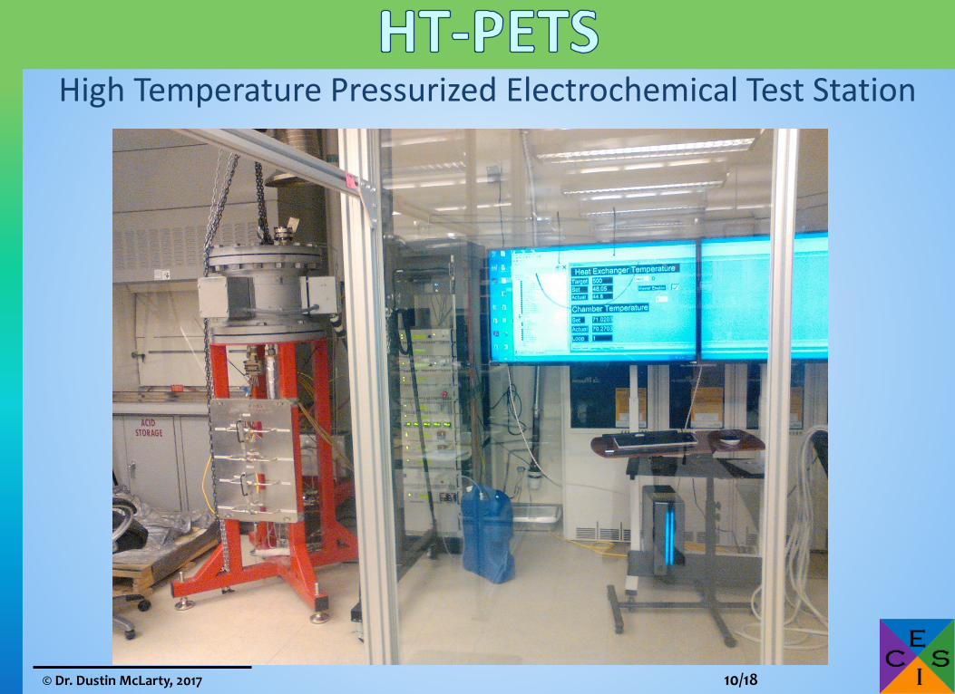
High Temperature Pressurized Electrochemical Test Station

11/18© Dr. Dustin McLarty, 2017

12/18© Dr. Dustin McLarty, 2017

13/18© Dr. Dustin McLarty, 2017
» Anonymous chart of SOFC cost per cell» List of cell characteristics
˃ Electrolyte support, materials for anode cathode
Support Anode Cathode Thickness (μm)
Rated Voltage @ 0.5A/cm2
Electrolyte NiO-GDC LSM-GDC 250 0.7
Electrolyte Ni-YSZ LSM 150 0.73
Electrolyte Ni-YSZ LSM 150 0.75
Electrolyte Ni-GDC LSCF 160 0.8
Anode 3 layers 2 layers 700 0.85
Anode GDC LSC 250 0.9

14/18© Dr. Dustin McLarty, 2017
» Wind + Solar powering the grid and making H2 for vehicles
» Using the existing natural gas storage as the nations battery
H2OO2
SOFCWGS / H2
recovery
H2O
CO2CH4
H2
Forward: Power Production
Steam Reforming
SOECPartial Methanation
CH4 / H2
separation
Reverse: Fuel ProductionH2

15/18© Dr. Dustin McLarty, 2017
» Removes SOFC from working fluid of gas turbine» SOFC heat balance by endothermic steam reforming» Facilitates passive hydrogen recovery
StateTemperature
(°C)Pressure
(MPa)1 27 0.12 207 0.43 900 0.44 900 0.035 50 0.036 420 1.57 25 1.58 357 1.59 750 1.5
10 900 0.411 927 0.412 655 0.113 329 0.1

16/18© Dr. Dustin McLarty, 2017
» 65 kWe microturbine, 0.49 kg/s» 3 ton/day oxygen membrane» 1,450 SLPM O2 compressor» 385kW SOFC stack @ 30% O2 recovery
˃ 61.7m2 of SOFC area @ 0.67A/cm2
˃ Equivalent to 260kW stack @0.5A/cm2 in 1atm air with 80% util
Full PowerPeak FTE efficiency
Net Power 668kW 432kWSOFC Voltage 0.86V 0.925V
Hydrogen Utilization 60% 72%Anode Recirculation 76% 66%Oxygen Recovered 53% 30%dFC-GT Efficiency 52% 72%
Anode Exhaust XH2 40% 24%
0.5 ton/day oxygen© Air Products 2014, 12th European Gasification Conference
Design Variable ValueASR .2Ω·cm2
FC Temperature 750°CSteam to Carbon 2.5
Turbine Press. 1.5MPaPermeate Press. 33kPaCompressor Eff. 80%
Turbine Eff. 80%Turbine Inlet 927°C
Assumptions Results
17/18© Dr. Dustin McLarty, 2017
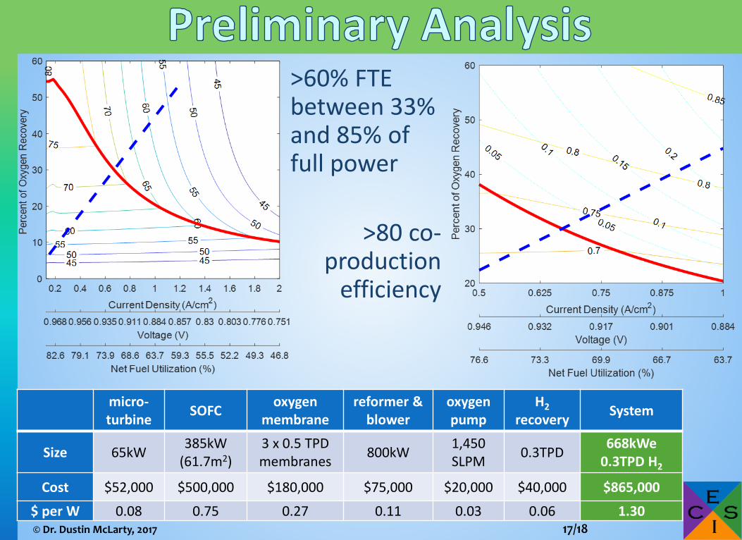
>60% FTE between 33% and 85% of full power
>80 co-production
efficiency
micro-turbine SOFC oxygen
membranereformer &
bloweroxygen pump
H2recovery System
Size 65kW 385kW (61.7m2)
3 x 0.5 TPD membranes 800kW 1,450
SLPM 0.3TPD 668kWe 0.3TPD H2
Cost $52,000 $500,000 $180,000 $75,000 $20,000 $40,000 $865,000
$ per W 0.08 0.75 0.27 0.11 0.03 0.06 1.30

18/18© Dr. Dustin McLarty, 2017
» High pressure SOFC testing» Oxygen cathode SOFC testing» Oxygen membrane tests with micro-turbine
pressures and vacuum pump» In-situ cell temperature measurements» Anode flow geometry for temperature profile
management» Hollow catalyzed anode plate for localized in-
stack methane reforming» In-situ methanation in electrolysis mode