Embed Size (px)
Citation preview

Crompton Instruments Integra
and Paladin Transducers


FeaturesExtensive range
High accuracy
True RMS measurement
THD measurement and power quality data
Pulsed, analogue and digital outputs
BenefitsCost saving remote metering
DIN-rail or base mounted options
Efficient monitoring, control and protection of expensive power assets
ApplicationsSwitchgear
Distribution systems
Generator sets
Control panels
Energy management
Building management
Utility power monitoring
Process control
Motor control
ApprovalsUL, CSA and BV
Contents Page
Integra 1560 and 1580 Digital Transducer Systems 2 – 6
Paladin Transducers AT Series Class 0.5 7 – 11
Paladin Transducers 250 Series Class 0.2 and 0.5 12 – 24
Paladin Transducers 250 Series Dimensions 25
Paladin Transducers 250 Series Connection Diagrams 26 – 29
Integra and Paladin Transducers
An extensive range of transducers providing measurement, isolation and conversion of electricalparameters into industry standard DC output signals. The range offers protection against highvoltage and overload, and resistance to vibration in harsh electrical environments.
The transducer range also offers multiple analogue outputs in a single housing and individualmeasurement of most electrical parameters.
1

Integra Digital Transducer Systems
Integra 1560 and 1580 transducers provide high accuracy <0.2%measurements and communicate up to 50 major electrical and powerquality parameters, including true RMS system values, power quality dataand total harmonic distortion (THD) measurement up to the 31st harmonic.The range includes the rail mounted 1560 DIN version and the 1580 variantwith a base plate for surface mounting.
OperationThe multi function Integra 1560 and 1580 transducers offer uncomplicatedoperation and high accuracy <0.2% measurement of single and three-phase voltage,current, frequency, Watts, VAr, VA, energy and power factor, and total harmonicdistortion measurement of both phase and system current and voltage. A simpleWindows based software package is provided to configure the transducer. Onceconfigured, up to 50 electrical and power quality variables can be simultaneouslyinput into building management systems via pulsed, analogue and digitalcommunication options. Status may also be monitored via a PC through a software package.
Alternatively, an optional menu driven display unit can be used to configure andmonitor up to 32 measured parameters. Display panel unit can be permanentlymounted next to the transducer or simply connected at times when configuration,adjustment and/or status information is required.
AccuracyIntegra transducers utilise true RMS measurement techniques up to the 31stharmonic, providing <0.2% accuracy. An exceptional tolerance to high harmonicfrequencies is achieved from the robust frequency detection method, which is ableto lock the fundamental frequency onto any phase. High integrity measurementsare possible where the system approximates CT current in the absence of voltage signals.
System InputDesigned for all low, medium and high voltage switchgear and distributionsystems, the transducers offer programmable VT and CT ratio capability. Directconnection up to 480V AC with 5A CT inputs is standard, and 1A CT inputs are optional.
System OutputsPulsed outputsOptional pulsed outputs enable retransmission of kWh and kVArh time basedparameters. Outputs are pulsed at a rate proportional to the measured kWh activeenergy, with programmable pulse width and rate. Output relays have fully insulatedvolt free contacts, with connection via screw clamp terminals.
Analogue outputsUp to four analogue outputs may be included, enabling transmission of linearparameters. Each analogue channel can be assigned to one of 47 measuredparameters with fully adjustable output span and can be configured to operate innormal, reverse, threshold or constant current modes. Analogue outputs share acommon return which is galvanically isolated from non-analogue output terminals.
RS485 Digital CommunicationsRS485 Modbus RTUIntegra 1560 and 1580 transducers have two RS485 communication ports fordirect connection to SCADA systems with Modbus RTU protocol, oroptionally a single Johnson Controls Metasys NII protocol. The Modbus optionincludes function 8 subfunction 0, which provides return query data diagnosticsupport and the ability to change Modbus word order to suit user requirements.
Lonworks OptionThe Lonworks option conforms to LonMark Interoperability Guidelines version 3.2.Transducers can be integrated into a single control network without requiring acustom node or network tool development. Lonworks implementations include aModbus port. This Modbus port is used when a local Integra display is required orfor setting up the unit from Crompton Instruments configuration software.
Features• Measure and communicate up to50 electrical and power parameters
• High accuracy of <0.2%
• THD measurement and powerquality data
• True RMS measurement
• Pulsed, analogue and digital outputs
• Modbus and Lonworks interfaceoptions
• Fully programmable VT and CT ratios
• Configurable via software or menudriven interface
Benefits • Replaces multiple single functiontransducers
• DIN-rail or base mounted options
• Local or remote configuration andmonitoring via building managementsystems
• ANSI style local or remote LEDdisplay option
• Monitoring, control and protectionof expensive power assets
Applications• Switchgear
• Distribution systems
• Control panels
• Energy management
• Building management
• Utility power monitoring
• Process control
• Motor monitoring
Approvals• UL file no. E200300
• CSA pending
2

Profibus OptionThe Profibus option provides an RS485 interface capable of operating at up to10Mb/s. Profibus implementations include a Modbus port. This Modbus port is usedwhen a local Integra display is required or for setting up the unit from Cromptonconfiguration software.
Software ConfigurationConfiguration of up to 50 measured parameters, outputs, pulsed relays, currentand power demands are programmed through a Windows style user interface.The transducer is connected to a PC’s COM port via an RS485/RS232 converter.
The software allows the user to load and save configuration settings to and from aPC hard disk, and to send and retrieve settings from the transducer. Settings canbe saved for later use and can be copied from one Integra transducer to another.
Status information is usually communicated into a building management system,but can also be monitored through configuration software. The softwareinterrogates the selected transducer every few seconds to obtain data, which canbe viewed on a dedicated measurements page.
Programmable Display Unit OptionAs an alternative to the standard software configuration package, voltage and currenttransformer ratios, communication options and power measurement parameters canbe configured via the optional menu driven Integra DIS-1540 display unit.
A simple two button interface on the front panel of the unit allows display of 32 majorelectrical and power quality parameters. All set-up screens are password protected.
Once configured, the status of each parameter can be viewed by scrolling through 13 screens, featuring a 3 line, 4 digit LED display. The unit requires an independentauxiliary power supply and thus may be positioned either locally, or remotely from the transducer at a distance limited only by the communication restrictions of RS485.
Programmable ParametersIntegra 1560 and 1580 transducers are programmed via the RS485communications port using the configuration software for a Windows based PC, or by using the optional programmable Integra DIS-1540 display unit.
3
Measurement and communicationUp to 50 electrical and power qualityparameters can be measured.
Volts L1-N, L2-N, L3-NVolts L1-L2, L2-L3, L3-L1System volts L-N (average)System volts L-L (average)Current line 1, 2 and 3System current (average)Current sumCurrent demandCurrent maximum demandNeutral currentSystem frequencyWatts 1, 2 and 3System Watts (sum)Watts demand (import)Watts maximum demand (import)Watt-hours (import)VAr 1, 2 and 3System VAr (sum)VAr-hours (import)VA 1, 2 and 3System VA (sum)Power factor 1, 2 and 3System power factor (average)Phase angle 1, 2 and 3System phase angle (average)THD volts 1, 2 and 3THD system volts (mean)THD amps 1, 2 and 3THD system amps (mean)
Measurement and display Up to 32 electrical and power qualitymeasurements can be configured andmonitored on the DIS-1540 optionaldisplay unit. These parameters appearin the following order.1 System volts
System currentSystem kW
2 System volts THD %System current THD %
3 Volts L1 – N (4-wire only)Volts L2 – N (4-wire only)Volts L3 – N (4-wire only)
4 Volts L1 – L2Volts L2 – L3Volts L3 – L1
5 Volts Line 1 THD %Volts Line 2 THD %Volts Line 3 THD %
6 Current L1Current L2Current L3
7 Current Line 1 THD %Current Line 2 THD %Current Line 3 THD %
8 Neutral current (4-wire only)FrequencyPower factor
9 kVArkVAkW
10 kW Hr (7 digit resolution)11 kVAr Hr (7 digit resolution)12 kW demand
Current demand13 kW maximum demand
Current maximum demand
Parameter Range
Password: 4 digit, 0000 - 9999Primary current: max 9999A (360MW max**)VT primary: 400kV (360MW max**)Secondary voltage: nominal system voltage
** maximum VT and CT ratios are limited so thecombination of primary voltage and current doesnot exceed 360MW at 120% of relevant input
Demand integration time: 8, 15, 20, 30 minutesReset: max demand and active energy registersPulse output duration: 60, 100, 200 msPulse rate divisors: 1, 10, 100, 1000RS485 interface baud rate: 2.4, 4.8, 9.6, 19.2kBRS485 parity: odd/even/no, 1 or 2 stop bitsModbus address: 1 - 247Analogue outputs: user definable parameters and ranges

4
Input
Nominal input voltage: 57.7 – 277V L-N, 100 – 480V L-LMax continuous input voltage: 120% of nominalMax short duration input voltage: 2 x for 1 second, repeated 10 times at 10 second intervalsSystem VT ratios (primary): any value up to 400kV **Nominal input voltage burden: < 0.2 VANominal input current: 5A (1A option)System CT primary values: 9999 max 360MW **Max continuous input current: 120% nominalMax short duration current input: 20 x for 1 second, repeated 5 times at 5 second intervalsNominal input current burden: < 0.6 VA
** maximum VT and CT ratios are limited so the combination of primary voltageand current does not exceed 360MW at 120% of relevant input
Outputs
RS485 communications: two-wire half duplex Baud rates: 2400, 4800, 9600, 19200Pulsed: clean contact SPNO, 100V DC 0.5A maxPulse duration: 60, 100 or 200 millisecondsPulsed outputs: up to 2 Analogue outputs: up to 4
Auxiliary
Standard nominal supply voltage: 100 – 250V, AC or DC (85 – 287V, AC absolute)(85 – 312V, DC absolute)
AC supply frequency range: 45 – 66HzAC supply burden: 6 VA Optional auxiliary DC supply: 12 – 48V, DC
(10.2 – 60V, DC absolute)DC supply burden: 6 VA
Measuring ranges
Voltage: 80 – 120% of nominal (functional 5 – 120%)Current: 5 – 120% of nominal (functional 5 – 120%)Frequency: 45 – 66HzPower factor: 0.8 capacitive – 1 – 0.8 inductiveTHD: Up to 31st harmonic 0% – 40%Energy: 7 digit resolution
Reference conditions
Ambient temperature: 23°±1°CInput frequency: 50 or 60Hz ±2%Input waveform: sinusoidal (distortion factor < 0.005)Auxiliary supply voltage: nominal ±1%Auxiliary supply frequency: nominal ±1%AC auxiliary supply waveform: sinusoidal (distortion factor < 0.05)Magnetic field of origin: terrestrial flux
Accuracy
Voltage: ±0.17% of range Current: ±0.17% of range Frequency: 0.15% of mid frequencyPower: ±0.2% of range Power factor: 1% of unityReactive power (VAr): ±0.5% of rangeApparent power (VA): ±0.2% of rangeTHD: ±1% Neutral current: ±0.95% of rangeEnergy: KWh 1% IEC1036KVArh: 2% Temperature coefficient: voltage and current typical: 0.013%/°C Watts typical: 0.018%/°CUpdate time: 1 second for display, 250 ms for optional digital portAnalogue output: ±0.2%
Specifications

Accuracy DefinitionError changes due to quantity variations as described in IEC688:1992 section 6.THD accuracy based on a typical harmonic profile.
5
Specifications continued
Enclosure
Enclosure style: DIN-rail or base mountedCompliant with: UL E200300 and IEC 1010/BSEN 61010-1Material: Polycarbonate with additional metal base plate on the 1580 for surface mountingTerminals: Shrouded screw clamp with additional metal base plate on the 1580 for surface
mountingDielectric voltage: Tested at 3.25kV RMS 50Hz for 1 minute between all electrical circuitsOperating temperature: -20 to +60°CStorage temperature: -30 to +80°CRelative humidity: 0 – 90% non condensingWarm-up time: 1 minuteShock: 30g in 3 planesVibration: 10 – 55Hz, 0.15mm amplitudeDIN-rail transducer dimensions: 5.5" high* x 3.72" wide x 3.72" deep
139.6mm high x 94.4mm wide x 94.4mm deep *Excluding connectorsBase mounted transducer 5.2" high* x 3.74" wide x 5.24" deepdimensions: 131.5mm high x 95mm wide x 133.5mm deep *Excluding connectorsTransducer display dimensions: 4.31" high x 4.31" wide x 2.9" deep
109.4mm high x 109.4mm wide x 73.7mm deepPanel cut out (display): 4.06" (103mm) diameter, 4 stud positions
Ordering Codes
INT-1561-*-5-**-option-*** Integra 1560 1-phase 5A CT input, DIN-railINT-1562-*-5-**-option-*** Integra 1560 1-phase 3-wire 5A CT input, DIN-railINT-1563-*-5-**-option-*** Integra 1560 3-phase 3-wire 5A CT input, DIN-railINT-1564-*-5-**-option-*** Integra 1560 3-phase 4-wire 5A CT input, DIN-railINT-1581-*-5-**-option-*** Integra 1580 1-phase 5A CT input, base mountINT-1582-*-5-**-option-*** Integra 1580 1-phase 3-wire 5A CT input, base mountINT-1583-*-5-**-option-*** Integra 1580 3-phase 3-wire 5A CT input, base mountINT-1584-*-5-**-option-*** Integra 1580 3-phase 4-wire 5A CT input, base mount*Input voltage suffixL 57.7–139V L-N 1561 and 1581
114–278V L-L (57.7–139V L-N) 1562 and 1582100–240V L-L (57.7–139V L-N) 1563,4 and 1583,4
M 140–277V L-N 1561 and 1581279–480V L-L (140–240V L-N) 1562 and 1582241–480V L-L (140–277V L-N) 1563,4 and 1583,4
**Auxiliary supply suffixL 12–48V DCM 100–250V AC/DC*** Communications suffix
Description Cat. no.
010 1011 1 1012 1 2013 1 3014 1 4020 1 1021 1 1 1022 1 1 2023 1 1 3024 1 1 4040 1 1060 1 1110 1 1111 1 1 1112 1 1 2113 1 1 3114 1 1 4120 1 1 1121 1 1 1 1122 1 1 1 2123 1 1 1 3124 1 1 1 4210 2 1220 2 1 1
Pulsed/relay
outputs
RS485 Modbus
RS485 interface
Modbus o
rJohnson Controls
Metasys NII
Profibus
Lonw
orks
Analo
gue
outputs
Sample order codeINT-1564-M-5-M-120
Integra 1560 transducer, 3-phase 4-wire, DIN-rail mounted, 241 to 480V L-L nominal input voltage, 5 A CTinput, auxiliary supply 100 – 250V AC or DC, one relay pulsed output and two RS485 Modbuscommunication ports.
Additional code for analogue outputs=1 0-20 mA, 10V compliance (user
configurable as 4-20 mA)=3 -1/0/+1 mA, 10V compliance

6
Dimensions
Integra 1560 DIN-rail Mounted Transducer
Optional Remote Display (for use with Integra 1560 or1580 Transducer)
Optional Remote Display Panel Cut-Out
1560/1580 - 3-phase 3-wire Unbalanced Load
Auxiliary SupplyThe Integra family should ideally be powered from a dedicated supply, either 100– 250V AC or DC (85V – 280 AC absolute or 85 – 312V DC absolute) or 12-48V DC(10.2 – 60V DC absolute). However, all Integra devices may be powered from asignal source, if in the working range of the chosen auxiliary supply.
FusingIt is recommended that all voltage lines be fitted with 1 amp fuses.
Safety/Ground ConnectionsFor safety reasons, all CT secondary connections should be grounded inaccordance with local regulations.
DIS-1540 Remote Display
1560/1580 - 3-phase 4-wire Unbalanced Load
Integra 1580 Base Mounted Transducer

7
Paladin AT Transducer Series
The new AT series of Paladin transducers provide a cost effective solution for AC current and voltage measurements.
The range provides measurement, isolation and conversion of electricalparameters into industry standard DC output signals. The range offersprotection against high voltage and overload, and resistance to vibrationin harsh electrical environments. The new range of transducers featuresuser selectable multiple analogue outputs in a single housing andindividual measurement of current, voltage and frequency.
The Paladin transducer range is the workhorse of the industry, thoroughlyproven and installed in thousands of locations across the world. The newAT range offers the same high quality performance and reliability in a cost effective package.
The product features a DIN-rail mounted enclosure, simple connection and user selectable analogue outputs. The AT series transducers willmeasure to class 0.5 accuracy.
OverviewPaladin AT transducers can be used for measuring the following parameters:
• True RMS AC current and voltage• Average sensing AC current and voltage (self powered)
Advantages• Converts high voltage signals to low voltage DC outputs• Limits voltage levels to the attached equipment• Provide a signal that can be transmitted from the measuring location to a remote point
SafetyPaladin AT transducers are designed for use in harsh electrical environments and feature:
• High protection against overload – 20 x rated current for 1 second• High degree of mechanical shock and vibration resistance• Protection against current open and short circuit and voltage open circuit• Inputs, outputs and power supply are galvanically isolated
Ordering InformationWhen ordering please specify
1. Product catalogue number (AT1, AT2)2. Current or voltage input3. Auxiliary power supply AC or DC (AT1 only)
An example of each product code is available on the product description pages ofthis brochure.
Features• DIN-rail enclosure
• Measurement of main electricalparameters
• Conversation to standard DC output signals
• User selectable output configuration
• Outputs suitable for indication and PLCs
• High accuracy
• Zero and span adjustments
• Single phase systems
• Flame retardant case
• Screw clamp terminals
Benefits• Cost effective remote metering
• Reduction of signal levels for ease of metering
• Isolated output for safety
• Short and open circuit protection
• UK manufactured
Applications• Switchgear
• Motor control centre, generating sets
• Energy management and buildingmanagement systems
Standards• IEC 61326
• IEC 61010-1
• IEC 62053-21
• EN60688
• IEC688
• AS1384
• ANSI. C37
• RoHS Compliant

General Specifications
Performance:Designed to comply with BS6253 part 1
EN60688IEC688AS1384ANSI C37
Input:Nominal input voltage Dependant upon device type (nominal 110V-480V AC)Max. continuous input overload voltage 120% of nominalMax. short duration input voltage 2 x range maximum for 1 second repeated 5 timesNominal input voltage burden <0.2VANominal input current Dependant upon device type. (Nominal 5 or 1A AC)Max. continuous input overload current 120% of nominalMax. short duration input current 20 x range maximum for 1 secondAuxiliary:Operating range 110-240V AC/DC +/-10%
12-48V DC +/-10%Accuracy:Accuracy class 0.5%Accuracy range 20-120%Response time < 400msec from 0-99% of rated output
< 250msec from 0-90%Outputs:DC outputs 0/1mA into 10KΩ(varies by model and 0/5mA into 2KΩselectable by the end user) 0/10mA into 1KΩ
0/20mA into 500Ω4/20mA into 500Ω0/10V into 1KΩ
Maximum output 24V DC when open circuitOutput ripple <0.5% full rated outputCurrent output protection Fully protected against open and short circuited outputVoltage output protection Fully protected against open circuited output.Span adjustment +/- 10%Zero adjustment +/- 2%Enclosure:Enclosure style DIN-rail mountDimensions (nominal) 75 x 90 x 60mm (AT1, AT2)Material Polycarbonate to UL94V0Weight Dependant upon device type (nominal 200-300g)Terminals Shrouded screw-clamp 0.05-4mm wireEnvironment:Operating temperature 0°C to +60°CTemperature Coefficient 0.03% per °C typicalStorage temperature -20°C to +70°CRelative humidity 0-95% non-condensingShock 30g in 3 planesVibration 10Hz to 50HzDielectric voltage Withstand test 3.25kV rms 50Hz for 1 minute between aux and measuring inputs
8

9
Paladin AT1 Transducer
True RMS Voltage & Current, Auxiliary PoweredA single-phase input transducer offering voltage or current measurementdown to 20% of the nominal input. It offers true RMS measurement of theinput voltage or current, measurement of non standard and distortedwaveforms and calibrated for sine waves with up to 30% of 3rd harmonic distortion.
The transducer is provided with isolation between input, output and auxiliary.
The transducers have a selection of outputs set by the end user.
General Specifications
Input: 110V, 120V, 130V, 150V, 200V, 220V, 230V, 240V, 250V, 380V, 400V, 415V, 440V, & 480V AC1A & 5A
Output: 0/1mA, 0/5mA, 0/10mA, 0/20mA, 4/20mA & 0/10V. User selectable via dip-switches, default 4/20mAFrequency: 50/60HzAuxiliary: 110-240 AC/DC
12-48V DC
Description Voltage Part number
True RMS Voltage Transducer AT1V-***-§To build a part number: Where -***- = Input Voltage 110V -110-
120V -120- 130V -130- 150V -150- 200V -200- 220V -220- 230V -230- 240V -240- 250V -250- 380V -380- 400V -400- 415V -415- 440V -440- 480V -480-
Where -§ = Auxiliary Voltage 12-48V DC -L110-240V AC/DC -M
Example: True RMS Voltage Transducer with 120V input and 110-240VAC/DC auxiliary AT1V-120-M
Product Code
Description Current Part number
True RMS Current Transducer AT1A-***-§To build a part number: Where -*- = Input Current 1A CT1
5A CT5Where -§ = Auxiliary Voltage 12-48V DC -L
110-240V AC/DC -M Example: True RMS Current Transducer with 5A input and 12-48V DC auxiliary AT1A-CT5-L

Paladin AT2 Transducer
Average Sensing Voltage & Current, Self PoweredA single-phase input transducer offering voltage and current measurementdown to 20% of the nominal input. Average sensing and calibrated to indicatethe RMS value of a sine wave with less than 1% distortion.
Internal power is derived from the input signal and will maintain accuracy to20% of full scale or less. The transducer is provided with isolation betweeninput and output.
The transducers have a selection of outputs set by the end user.
General Specifications
Input: 110V, 120V, 130V, 150V, 200V, 220V, 230V, 240V, 250V, 380V, 400V, 415V, 440V, & 480V AC1A & 5A
Output: 0/1mA, 0/5mA, 0/10mA & 0/20mA. User selectable via dip-switches, default 0/20mAFrequency: 50/60Hz
10
Description Voltage Part number
Self Powered Voltage Transducer AT2V-***To build a part number: Where -***- = Input Voltage 110V -110-
120V -120- 130V -130- 150V -150- 200V -200- 220V -220- 230V -230- 240V -240- 250V -250- 380V -380- 400V -400- 415V -415- 440V -440- 480V -480-
Example: Self Powered Voltage Transducer with 120V input AT2V-120
Product Code
Description Current Part number
Self Powered Current Transducer AT2A-***To build a part number: Where -*- = Input Current 1A CT1
5A CT5Example: Self Powered Current Transducer with 5A input AT2A-CT5

11
Connection Diagrams
True RMS Voltage & Current Transducer Average Sensing Voltage & Current Transducer
Analogue Output Dip Switch Selection Guide
True RMS Voltage & Current Transducer Average Sensing Voltage & Current Transducer
Dimensions
0/1mA
0/5mA
0/1mA
0/5mA
0/10mA
0/10mA0/20mA
0/20mA4/20mA
0/10V
AT1A AT1V AT2A AT2V
Notes
Auxiliary supply applies only if ordered.
For maximum performance an AC or DC auxiliary is recommended.
Self powering is achievable for a voltage variation of less than 20%.

12
Paladin Transducers 250 Series Class 0.5 and Class 0.2
An extensive range of transducers providing measurement, isolation and conversion of electrical parameters into industry standard DC output signals. The range offers protection against high voltage andoverload, and resistance to vibration in harsh electrical environments. The transducer range also offers multiple analogue outputs in a singlehousing and individual measurement of most electrical parameters.
Advantages• Convert high voltage signals to a low voltage DC output• Limit voltage levels to the attached equipment and minimise the possibility of overloads or transients being passed on
• Provide a signal that can be transmitted from the measuring location to a remote point
SafetyCrompton transducers and transmitters are designed for use in harsh electricalenvironments and feature:• High protection against overload - 20 x rated current for 1 second• High degree of mechanical shock and vibration resistance• Protection against high voltage• Inputs, outputs and power supply are galvanically isolated (excluding resistance transmitters)
Ordering Information When ordering please specify:1. Product catalogue number2. Current and/or voltage3. Frequency4. Auxiliary voltage AC or DC5. For power products:
a. VT & CT ratiosb. System configuration i.e. single-phase, three-phase, three or four-wire,balanced or unbalanced load
c. required primary power level for DC full output6. National specification indicated by 7th digit in the product number
253 Paladin Transducers, Class 0.5The workhorse of the industry, thoroughly proven and installed in thousands oflocations across the world. This range offers a very wide range of functions tocomplement the 256 Paladin range of power transducers. Functions includeVoltage, current, frequency, tap position and resistance.
256 Paladin Transducers, Class 0.5The industry standard power transducer, incredibly popular and available in a hugerange of metering options. Power transducers are also available to special orderwith calibration at non standard frequencies. Alongside the Watt, VAr and VAtransducers, the range also includes 3 in one current or voltage transducers and aDC to DC transducer.
252 Paladin Advantage Transducers, Class 0.2Our premium range of higher specification transducers for voltage current andfrequency offering Class 0.2 measurement of up to eight electrical parameters.These products are housed in an industry standard 2” (50mm) wide case. Therange offers resistance to EMC protection against high voltage and overload,temperature extremes and resistance to vibration in harsh electrical environments.
256-X Paladin Advantage Transducers, Class 0.2Complementing the 252 Paladin Advantage range and offering multiple outputs anda wide range of options. The 256-X Paladin Advantage products include Watt, VAr,VA, power factor, phase angle, and 3 in 1 voltage, current, or voltage/current/frequency transducers.
250 Signal IsolatorOffers DC isolation of 0-20mA or 4-20mA signals.
Measured Parameters• AC and DC current and voltage• Active (Watts), reactive (VAr) andapparent (VA) power
• Frequency• Power factor and phase angle• Suppressed zero voltage for a narrow voltage range
• Tap position on a high voltagetransformer
• Temperature transmitters forresistance thermometer detectors(RTD’s)
• Resistance transmitters
Features• Measurement of most electricalparameters
• Conversion to standard DC output signals
• Outputs suitable for indication, PLCs
• High accuracy
• Multiple outputs in single housing
• Exceptional waveforms handling
• Zero and span adjustments
• Single and three-phase systems
• Flame retardant cases
• Screw clamp terminals
• DIN-rail mounting
Benefits• Cost savings remote metering
• Reduction of signal levels for ease of metering
• Isolated output for safety
• Protection against high voltage and overload
Applications• Switchgear motor control centres,generating sets, energy managementand building management systems
13
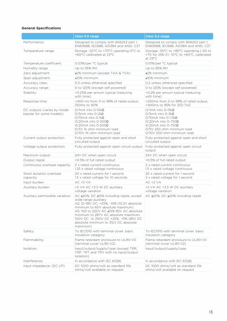
Class 0.5 range Class 0.2 range
Performance: Designed to comply with BS6253 part 1, Designed to comply with BS6253 part 1,EN60688, IEC688, AS1384 and ANSI. C37 EN60688, IEC688, AS1384 and ANSI. C37
Temperature range: Storage -20°C to +70°C operating 0°C to Storage -55°C to +85°C operating (-20 to+60°C calibrated at 23°C +70 for 256-X) -10°C to +60°C, calibrated
at 23°C
Temperature coefficient: 0.03%/per °C typical 0.01%/per °C typical
Humidity range: Up to 95% RH Up to 95% RH
Zero adjustment: ±2% minimum (except TAA & TVA) ±2% minimum Span adjustment: ±10% minimum ±10% minimum Accuracy class: 0.5 unless otherwise specified 0.2 unless otherwise specified
Accuracy range: 0 to 120% (except self powered) 0 to 120% (except self powered)
Stability: +0.25% per annum typical (reducing +0.2% per annum typical (reducing with time) with time)
Response time: <400 ms from 0 to 99% of rated output, <200ms from 0 to 99% of rated output,250ms to 90% <400ms to 95% for 253-THZ
DC outputs (varies by model 0/1mA into 0-10kΩ 0/1mA into 0-15kΩbipolar for some models): 0/5mA into 0-2kΩ 0/5mA into 0-3kΩ
0/10mA into 0-1kΩ 0/10mA into 0-1.5kΩ0/20mA into 0-500Ω 0/20mA into 0-750Ω4/20mA into 0-500Ω 4/20mA into 0-750Ω0/5V 1k ohm minimum load 0/5V 250 ohm minimum load 0/10V 1K ohm minimum load 0/10V 500 ohm minimum load
Current output protection: Fully protected against open and short Fully protected against open and shortcircuited output circuited output
Voltage output protection: Fully protected against open circuit output Fully protected against open circuit output
Maximum output: 24V DC when open circuit 24V DC when open circuit
Output ripple: <0.5% of full rated output <0.5% of full rated output
Continuous overload capacity: 2 x rated current continuous 2 x rated current continuous1.25 x rated voltage continuous 1.5 x rated voltage continuous
Short duration overload 20 x rated current for 1 second 20 x rated current for 1 secondcapacity: 1.5 x rated voltage for 10 seconds 2 x rated voltage for 1 second
Input burden: AC <2 VA AC <2 VA
Auxiliary burden: <2 VA AC <3.5 W DC auxiliary <2 VA AC <3.5 W DC auxiliary voltage variation voltage variation
Auxiliary permissible variation: AC ±20%, DC ±15% including ripple, except AC ±20%, DC ±20% including ripple wide range auxiliaryA2: 12-48V DC, +25%, -15% (10.2V absolute minimum to 60V absolute maximum)A5: 100 to 250V AC ±15% 85V AC absolute minimum to 287V AC absolute maximum, 100V DC to 250V DC +25%, -15% (85V DC absolute minimum to 312V DC absolute maximum)
Safety: To IEC1010 with terminal cover, basic To IEC1010 with terminal cover, basicinsulation category insulation category
Flammability: Flame retardant enclosure to UL90-V0 Flame retardant enclosure to UL90-V0(terminal cover UL90-V2) (terminal cover UL90-V2)
Isolation: Input/output/supply/case (except TRR, Input/output/supply/case TRP, TRT and TRV with no input/output isolation)
Interference: In accordance with IEC 61326 In accordance with IEC 61326
Input impedance: (DC I/P) DC 1000 ohms/volt as standard 10k DC 1000 ohms/volt as standard 10kohms/volt available on request ohms/volt available on request
General Specifications

14
AC Current Average Sensing - Self PoweredAverage sensing and calibrated to indicate the RMS value of a sine wave with lessthan 1% distortion. Internal power is derived from the input signal and will maintainaccuracy to 20% of full scale or less. Input and output are isolated.
AC Current Average Sensing - Auxiliary PoweredSingle or three-phase models offering current measurement down to zero input.Average sensing and calibrated to indicate the RMS value of a sine wave with up to 1%distortion. Input, output and auxiliary are isolated.
Model Accuracy Function Connectiondiagram
253-TAL Class 0.5 AC current average sensing, 75mm(3") case 6256-TAL Class 0.5 AC current average sensing, 3-phase 2
3 DC outputs, 150mm(6") case252-XAL Class 0.2 AC current average sensing, 50mm(2") case 6
Model Accuracy Function Connectiondiagram
253-TAA Class 0.5 AC current average sensing, 75mm(3") case 1252-XAA Class 0.2 AC current average sensing, 50mm(2") case 1
Model Accuracy Function Connectiondiagram
253-TAR Class 0.5 AC current RMS sensing, 75mm(3") case 6256-TAR Class 0.5 AC current RMS sensing, 3-phase, 2
3 DC outputs, 150mm(6") case252-XAR Class 0.2 AC current RMS sensing, 50mm(2") case 6256-XAR Class 0.2 AC current RMS sensing, 3-phase, 2
3 DC outputs, 150mm(6") case
Specifications
Input: 1A, 5A or 10A ACOutput: 0/1mA, 0/5mA, 0/10mA or 0/20mA DC
0/1V, 0/5V or 0/10V DCCurrent: 1 or 5A ACFrequency: 50Hz, 60Hz
Specifications
Current Transducers
True RMS Current – Auxiliary PoweredSingle or three-phase models offering current measurement down to zero input.True RMS measurement of the input current, measuring non standard and distortedwaveforms. Calibrated for sine waves with up to 30% of 3rd harmonic distortion.Isolation is provided between input, output and auxiliary.
Input: 1A, 5A or 10A ACOutput: 0/1mA, 0/5mA, 0/10mA, 0/20mA or 4/20mA DC
0/1V, 0/5V or 0/10V DCCurrent: 1 or 5A ACFrequency: 50Hz, 60Hz Auxiliary*: 100-480V AC
12V, 24V, 48V, 110V or 125V DC
Specifications
*Max AC Aux on 256-TAL is 300V
*Max AC Aux on 256-TAR is 300V
Input: 1A, 5A or 10A ACOutput: 0/1mA, 0/5mA, 0/10mA, 0/20mA or 4/20mA DC
0/1V, 0/5V or 0/10V DCCurrent: 1 or 5A ACFrequency: 50Hz, 60HzAuxiliary*: 100-480V AC
12V, 24V, 48V, 110V or 125V DC
15
Model Accuracy Function Connectiondiagram
253-TVL Class 0.5 AC voltage average sensing, 75mm(3") case 15256-TVL Class 0.5 AC voltage average sensing, 3-phase 11
3 DC outputs, 150mm(6") case252-XVL Class 0.2 AC voltage average sensing, 50mm(2") case 15
Model Accuracy Function Connectiondiagram
253-TVA Class 0.5 AC voltage average sensing, 75mm(3") case 10252-XVA Class 0.2 AC voltage average sensing, 50mm(2") case 10
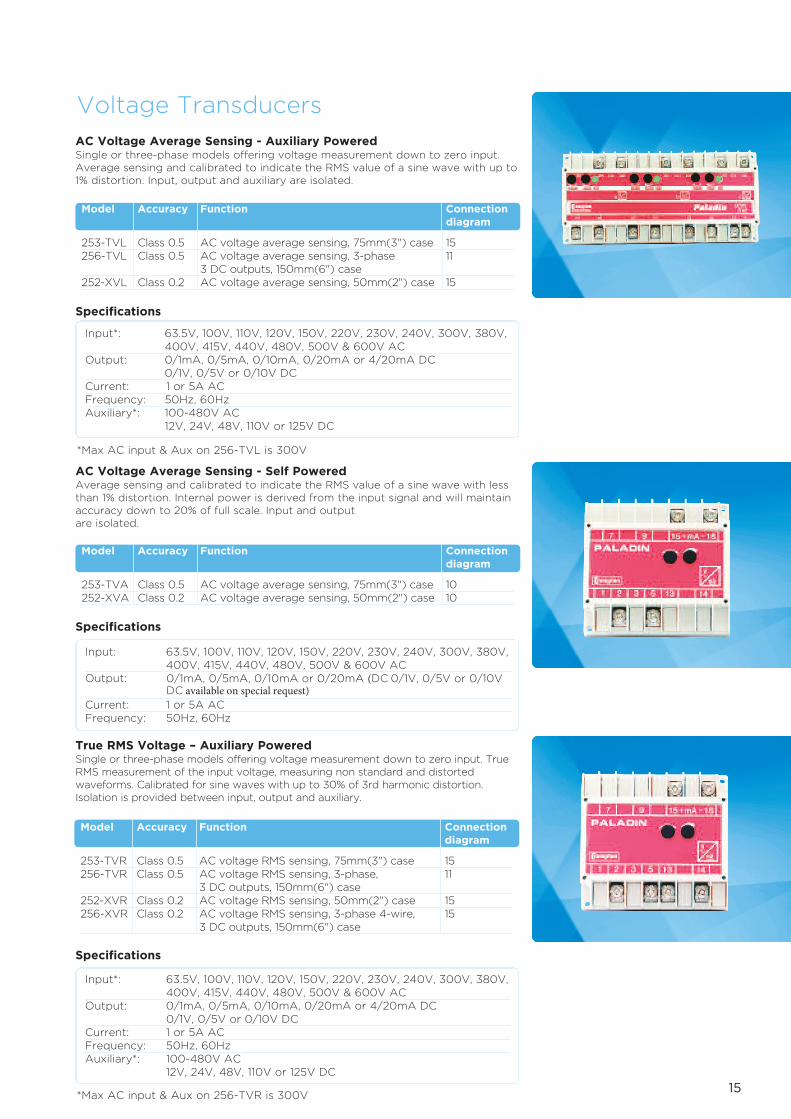
AC Voltage Average Sensing - Auxiliary PoweredSingle or three-phase models offering voltage measurement down to zero input.Average sensing and calibrated to indicate the RMS value of a sine wave with up to1% distortion. Input, output and auxiliary are isolated.
Input*: 63.5V, 100V, 110V, 120V, 150V, 220V, 230V, 240V, 300V, 380V,400V, 415V, 440V, 480V, 500V & 600V AC
Output: 0/1mA, 0/5mA, 0/10mA, 0/20mA or 4/20mA DC0/1V, 0/5V or 0/10V DC
Current: 1 or 5A ACFrequency: 50Hz, 60Hz Auxiliary*: 100-480V AC
12V, 24V, 48V, 110V or 125V DC
Specifications
*Max AC input & Aux on 256-TVL is 300V
Voltage Transducers
AC Voltage Average Sensing - Self PoweredAverage sensing and calibrated to indicate the RMS value of a sine wave with lessthan 1% distortion. Internal power is derived from the input signal and will maintainaccuracy down to 20% of full scale. Input and output are isolated.
Input: 63.5V, 100V, 110V, 120V, 150V, 220V, 230V, 240V, 300V, 380V,400V, 415V, 440V, 480V, 500V & 600V AC
Output: 0/1mA, 0/5mA, 0/10mA or 0/20mA (DC 0/1V, 0/5V or 0/10V DC available on special request)
Current: 1 or 5A ACFrequency: 50Hz, 60Hz
Specifications
True RMS Voltage – Auxiliary PoweredSingle or three-phase models offering voltage measurement down to zero input. TrueRMS measurement of the input voltage, measuring non standard and distortedwaveforms. Calibrated for sine waves with up to 30% of 3rd harmonic distortion.Isolation is provided between input, output and auxiliary.
Input*: 63.5V, 100V, 110V, 120V, 150V, 220V, 230V, 240V, 300V, 380V,400V, 415V, 440V, 480V, 500V & 600V AC
Output: 0/1mA, 0/5mA, 0/10mA, 0/20mA or 4/20mA DC 0/1V, 0/5V or 0/10V DC
Current: 1 or 5A ACFrequency: 50Hz, 60Hz Auxiliary*: 100-480V AC
12V, 24V, 48V, 110V or 125V DC
Specifications
*Max AC input & Aux on 256-TVR is 300V
Model Accuracy Function Connectiondiagram
253-TVR Class 0.5 AC voltage RMS sensing, 75mm(3") case 15256-TVR Class 0.5 AC voltage RMS sensing, 3-phase, 11
3 DC outputs, 150mm(6") case252-XVR Class 0.2 AC voltage RMS sensing, 50mm(2") case 15256-XVR Class 0.2 AC voltage RMS sensing, 3-phase 4-wire, 15
3 DC outputs, 150mm(6") case

AC Voltage Suppressed Zero – Auxiliary or Self PoweredSingle or three-phase models offering ‘expanded scale’ measurements at criticalvoltage levels, indicating small changes within a large voltage span. Average sensingand calibrated to indicate the RMS value of a sine wave less than 1% distortion.Isolation is provided between input, output and auxiliary.
Frequency Sensing - Self PoweredProvides a DC output which is directly proportional to input frequency. Internalpower is derived from the input signal and will maintain accuracy between 80% and120% or better of nominal input voltage. Input and output are isolated.
Frequency Sensing - Auxiliary PoweredProvides a DC output which is directly proportional to input frequency. Internalpower is derived from the input signal and will maintain accuracy whist the auxiliaryinput is within specification limits. 253-THZ offers AC auxiliary and 252-THL/Z caters for both AC and DC auxiliary. Isolation is provided between input, output and auxiliary.
16
Input*: Between +/-10% and +/-30% of nominal63.5V, 100V, 110V, 120V, 139V, 208V, 220V, 240V, 250V, 277V,380V, 400V, 415V, 440V, & 480V AC
Output: 0/1mA, 0/5mA, 0/10mA or 0/20mA DC 0/1V, 0/5V or 0/10V DCCurrent: 1 or 5A ACFrequency: 50Hz, 60HzAuxiliary: 100-480V AC
12V, 24V, 48V, 110V or 125V DC
Specifications
Input: 63.5V, 100V, 110V, 120V, 139V, 208V, 220V, 240V, 250V, 277V,380V, 400V, 415V, 440V, & 480V AC
Output: 0/1mA, 0/5mA, 0/10mA or 0/20mA DC0/1V, 0/5V or 0/10V DC
Current: 1 or 5A ACFrequency: 45/55Hz, 55/65Hz, 45/65Hz Auxiliary: 100-480V AC
12V, 24V, 48V, 110V or 125V DC
Specifications
Input: 63.5V, 100V, 110V, 120V, 139V, 208V, 220V, 240V, 250V, 277V,380V, 400V, 415V, 440V, & 480V AC
Output: 0/1mA, 0/5mA, 0/10mA or 0/20mA DC0/1V, 0/5V or 0/10V DC
Current: 1 or 5A ACFrequency: 45/55Hz, 55/65Hz, 45/65Hz & 360/440Hz
Specifications
Frequency Transducers
Model Accuracy Function Connectiondiagram
253-TVZ Class 0.5 AC voltage RMS sensing suppressed zero, 1550mm(2") case - self powered
256-XVZ Class 0.2 AC voltage RMS sensing suppressed zero, 153-phase 4-wire, 3 DC outputs, 150mm(6") case - auxiliary powered
Model Accuracy Function Connectiondiagram
253-THZ Class 0.5 Frequency sensing, 75mm(3") case 10252-XHA Class 0.2 Frequency sensing, 50mm(2") case 10
Model Accuracy Function Connectiondiagram
252-THL Class 0.2 Frequency sensing, live zero 50mm(2") case 15252-THS Class 0.2 Frequency sensing, true zero 50mm(2") case 15

17
Input: 57.7V, 63.5V, 100V, 110V, 120V, 139V, 208V, 220V, 240V, 250V,277V, 380V, 400V, 415V, 440V, & 480V AC
Output: 0/1mA, 0/5mA, 0/10mA, 0/20mA or 4/20mA DC1/0/1mA, 5/0/5mA, 10/0/10mA or 20/0/20mA DC0/1V, 0/5V or 0/10V DC1/0/1V, 5/0/5V or 10/0/10V DC
Current: 1 or 5A ACFrequency: 50Hz, 60Hz Optional 100-480V AC Auxiliary: 12V, 24V, 48V, 110V or 125V DC
Specifications
Watt Transducers – Auxiliary or Self PoweredA range of Watt transducers in single or three-phase, balanced or unbalanced, 3 or 4-wire systems. Class 0.5 products utilise the well established ‘time division multiplication’method of measuring power while the class 0.2 products are microprocessor based and offer exceptional waveform handling on distorted waveforms. In the self powered products the system voltage provides both power supply and input to themeasurements circuit but for systems with large voltage variations auxiliary poweredproducts should be used. Input, output and auxiliaries are isolated.
Power Transducers
Model Accuracy Function Connectiondiagram
256-TWK Class 0.5 1-phase, 150mm(6") case 14256-TWL Class 0.5 3-phase 3-wire balanced load, 150mm(6") case 19256-TWH Class 0.5 3-phase 4-wire balanced load, 150mm(6") case 24256-TWM Class 0.5 3-phase 3-wire unbalanced load, 20
150mm(6") case256-TWN Class 0.5 3-phase 4-wire unbalanced load, 35
150mm(6") case256-TWS Class 0.5 3-phase 3-wire balanced load (2 voltage 38
connections), 150mm(6") case256-XWK Class 0.2 1-phase, 150mm(6") case 14256-XWL Class 0.2 3-phase 3-wire balanced load, 150mm(6") case 41256-XWH Class 0.2 3-phase 4-wire balanced load, 150mm(6") case 24256-XWM Class 0.2 3-phase 3-wire unbalanced load, 20
150mm(6") case256-XWW Class 0.2 3-phase 4-wire unbalanced load, 21
150mm(6") case
18
Input: 57.7V, 63.5V, 100V, 110V, 120V, 139V, 208V, 220V, 240V, 250V,277V, 380V, 400V, 415V, 440V, & 480V AC
Output: 0/1mA, 0/5mA, 0/10mA, 0/20mA or 4/20mA DC1/0/1mA, 5/0/5mA, 10/0/10mA or 20/0/20mA DC0/1V, 0/5V or 0/10V DC1/0/1V, 5/0/5V or 10/0/10V DC
Current: 1 or 5A ACFrequency: 50Hz, 60Hz Optional 100-480V ACAuxiliary: 12V, 24V, 48V, 110V or 125V DC
Specifications
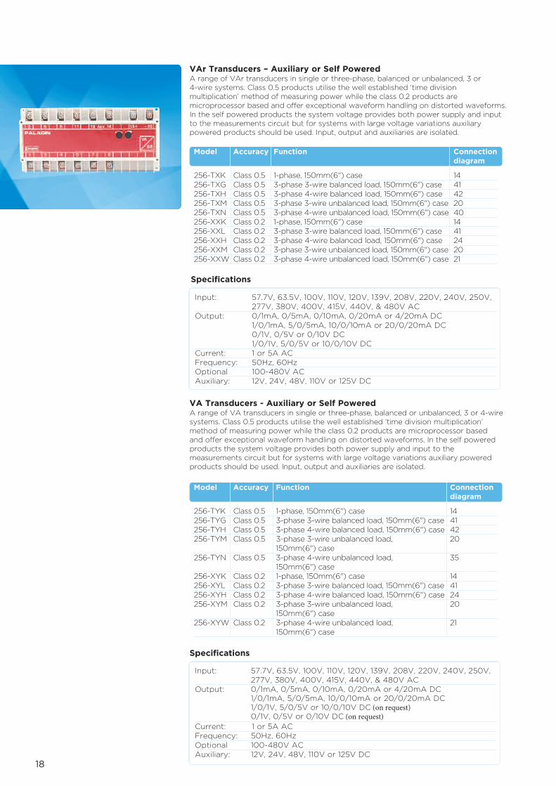
VAr Transducers – Auxiliary or Self PoweredA range of VAr transducers in single or three-phase, balanced or unbalanced, 3 or 4-wire systems. Class 0.5 products utilise the well established ‘time divisionmultiplication’ method of measuring power while the class 0.2 products aremicroprocessor based and offer exceptional waveform handling on distorted waveforms.In the self powered products the system voltage provides both power supply and inputto the measurements circuit but for systems with large voltage variations auxiliarypowered products should be used. Input, output and auxiliaries are isolated.
VA Transducers - Auxiliary or Self PoweredA range of VA transducers in single or three-phase, balanced or unbalanced, 3 or 4-wiresystems. Class 0.5 products utilise the well established ‘time division multiplication’method of measuring power while the class 0.2 products are microprocessor based and offer exceptional waveform handling on distorted waveforms. In the self poweredproducts the system voltage provides both power supply and input to themeasurements circuit but for systems with large voltage variations auxiliary poweredproducts should be used. Input, output and auxiliaries are isolated.
Input: 57.7V, 63.5V, 100V, 110V, 120V, 139V, 208V, 220V, 240V, 250V,277V, 380V, 400V, 415V, 440V, & 480V AC
Output: 0/1mA, 0/5mA, 0/10mA, 0/20mA or 4/20mA DC 1/0/1mA, 5/0/5mA, 10/0/10mA or 20/0/20mA DC 1/0/1V, 5/0/5V or 10/0/10V DC (on request)0/1V, 0/5V or 0/10V DC (on request)
Current: 1 or 5A ACFrequency: 50Hz, 60Hz Optional 100-480V ACAuxiliary: 12V, 24V, 48V, 110V or 125V DC
Specifications
Model Accuracy Function Connectiondiagram
256-TXK Class 0.5 1-phase, 150mm(6") case 14256-TXG Class 0.5 3-phase 3-wire balanced load, 150mm(6") case 41256-TXH Class 0.5 3-phase 4-wire balanced load, 150mm(6") case 42256-TXM Class 0.5 3-phase 3-wire unbalanced load, 150mm(6") case 20256-TXN Class 0.5 3-phase 4-wire unbalanced load, 150mm(6") case 40256-XXK Class 0.2 1-phase, 150mm(6") case 14256-XXL Class 0.2 3-phase 3-wire balanced load, 150mm(6") case 41256-XXH Class 0.2 3-phase 4-wire balanced load, 150mm(6") case 24256-XXM Class 0.2 3-phase 3-wire unbalanced load, 150mm(6") case 20256-XXW Class 0.2 3-phase 4-wire unbalanced load, 150mm(6") case 21
Model Accuracy Function Connectiondiagram
256-TYK Class 0.5 1-phase, 150mm(6") case 14256-TYG Class 0.5 3-phase 3-wire balanced load, 150mm(6") case 41256-TYH Class 0.5 3-phase 4-wire balanced load, 150mm(6") case 42256-TYM Class 0.5 3-phase 3-wire unbalanced load, 20
150mm(6") case256-TYN Class 0.5 3-phase 4-wire unbalanced load, 35
150mm(6") case256-XYK Class 0.2 1-phase, 150mm(6") case 14256-XYL Class 0.2 3-phase 3-wire balanced load, 150mm(6") case 41256-XYH Class 0.2 3-phase 4-wire balanced load, 150mm(6") case 24256-XYM Class 0.2 3-phase 3-wire unbalanced load, 20
150mm(6") case256-XYW Class 0.2 3-phase 4-wire unbalanced load, 21
150mm(6") case
19
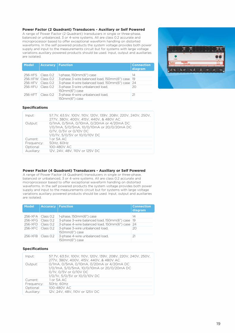
Power Factor (2 Quadrant) Transducers - Auxiliary or Self PoweredA range of Power Factor (2 Quadrant) transducers in single or three-phase,balanced or unbalanced, 3 or 4-wire systems. All are class 0.2 accurate andmicroprocessor based to offer exceptional waveform handling on distortedwaveforms. In the self powered products the system voltage provides both powersupply and input to the measurements circuit but for systems with large voltagevariations auxiliary powered products should be used. Input, output and auxiliariesare isolated.
Input: 57.7V, 63.5V, 100V, 110V, 120V, 139V, 208V, 220V, 240V, 250V,277V, 380V, 400V, 415V, 440V, & 480V AC
Output: 0/1mA, 0/5mA, 0/10mA, 0/20mA or 4/20mA DC1/0/1mA, 5/0/5mA, 10/0/10mA or 20/0/20mA DC0/1V, 0/5V or 0/10V DC1/0/1V, 5/0/5V or 10/0/10V DC
Current: 1 or 5A ACFrequency: 50Hz, 60Hz Optional 100-480V AC Auxiliary: 12V, 24V, 48V, 110V or 125V DC
Specifications
Model Accuracy Function Connectiondiagram
256-XFS Class 0.2 1-phase, 150mm(6") case 14256-XFW Class 0.2 3-phase 3-wire balanced load, 150mm(6") case 19256-XFV Class 0.2 3-phase 4-wire balanced load, 150mm(6") case 24256-XFU Class 0.2 3-phase 3-wire unbalanced load, 20
150mm(6") case256-XFT Class 0.2 3-phase 4-wire unbalanced load, 21
150mm(6") case
Power Factor (4 Quadrant) Transducers - Auxiliary or Self PoweredA range of Power Factor (4 Quadrant) transducers in single or three-phase,balanced or unbalanced, 3 or 4-wire systems. All are class 0.2 accurate andmicroprocessor based to offer exceptional waveform handling on distortedwaveforms. In the self powered products the system voltage provides both powersupply and input to the measurements circuit but for systems with large voltagevariations auxiliary powered products should be used. Input, output and auxiliariesare isolated.
Input: 57.7V, 63.5V, 100V, 110V, 120V, 139V, 208V, 220V, 240V, 250V,277V, 380V, 400V, 415V, 440V, & 480V AC
Output: 0/1mA, 0/5mA, 0/10mA, 0/20mA or 4/20mA DC1/0/1mA, 5/0/5mA, 10/0/10mA or 20/0/20mA DC0/1V, 0/5V or 0/10V DC1/0/1V, 5/0/5V or 10/0/10V DC
Current: 1 or 5A ACFrequency: 50Hz, 60Hz Optional 100-480V AC Auxiliary: 12V, 24V, 48V, 110V or 125V DC
Specifications
Model Accuracy Function Connectiondiagram
256-XFA Class 0.2 1-phase, 150mm(6") case 14256-XFG Class 0.2 3-phase 3-wire balanced load, 150mm(6") case 19256-XFD Class 0.2 3-phase 4-wire balanced load, 150mm(6") case 24256-XFC Class 0.2 3-phase 3-wire unbalanced load, 20
150mm(6") case256-XFB Class 0.2 3-phase 4-wire unbalanced load, 21
150mm(6") case

20
Phase Angle (2 Quadrant) Transducers - Auxiliary or Self PoweredA range of Phase Angle (2 Quadrant) transducers in single or three-phase,balanced or unbalanced, 3 or 4-wire systems. All are class 0.2 accurate andmicroprocessor based to offer exceptional waveform handling on distortedwaveforms. In the self powered products the system voltage provides both powersupply and input to the measurements circuit but for systems with large voltagevariations auxiliary powered products should be used. Input, output and auxiliariesare isolated.
Input: 57.7V, 63.5V, 100V, 110V, 120V, 139V, 208V, 220V, 240V, 250V,277V, 380V, 400V, 415V, 440V, & 480V AC
Output: 0/1mA, 0/5mA, 0/10mA, 0/20mA or 4/20mA DC1/0/1mA, 5/0/5mA, 10/0/10mA or 20/0/20mA DC0/1V, 0/5V or 0/10V DC1/0/1V, 5/0/5V or 10/0/10V DC
Current: 1 or 5A ACFrequency: 50Hz, 60Hz Optional 100-480V AC Auxiliary: 12V, 24V, 48V, 110V or 125V DC
Specifications
Phase Angle (4 Quadrant) Transducers - Auxiliary or Self PoweredA range of Phase Angle (4 Quadrant) transducers in single or three-phase, balancedor unbalanced, 3 or 4-wire systems. All are class 0.2 accurate and microprocessorbased to offer exceptional waveform handling on distorted waveforms. In the selfpowered products the system voltage provides both power supply and input to themeasurements circuit but for systems with large voltage variations auxiliarypowered products should be used. Input, output and auxiliaries are isolated.
Input: 57.7V, 63.5V, 100V, 110V, 120V, 139V, 208V, 220V, 240V, 250V,277V, 380V, 400V, 415V, 440V, & 480V AC
Output: 0/1mA, 0/5mA, 0/10mA, 0/20mA or 4/20mA DC1/0/1mA, 5/0/5mA, 10/0/10mA or 20/0/20mA DC 0/1V, 0/5V or 0/10V DC1/0/1V, 5/0/5V or 10/0/10V DC
Current: 1 or 5A ACFrequency: 50Hz, 60Hz Optional 100-480V AC Auxiliary: 12V, 24V, 48V, 110V or 125V DC
Specifications
Model Accuracy Function Connectiondiagram
256-XPS Class 0.2 1-phase, 150mm(6") case 14256-XPW Class 0.2 3-phase 3-wire balanced load, 150mm(6") case 19256-XPV Class 0.2 3-phase 4-wire balanced load, 150mm(6") case 24256-XPU Class 0.2 3-phase 3-wire unbalanced load, 20
150mm(6") case256-XPT Class 0.2 3-phase 4-wire unbalanced load, 21
150mm(6") case
Model Accuracy Function Connectiondiagram
256-XPA Class 0.2 1-phase, 150mm(6") case 14256-XPG Class 0.2 3-phase 3-wire balanced load, 150mm(6") case 19256-XPD Class 0.2 3-phase 4-wire balanced load, 150mm(6") case 24256-XPC Class 0.2 3-phase 3-wire unbalanced load, 20
150mm(6") case256-XPB Class 0.2 3-phase 4-wire unbalanced load, 21

21
Model Accuracy Function Connectiondiagram
256-XDK Class 0.2 1-phase, 150mm(6") case 14256-XDL Class 0.2 3-phase 3-wire balanced load, 150mm(6") case 25256-XDH Class 0.2 3-phase 4-wire balanced load, 150mm(6") case 26256-XDM Class 0.2 3-phase 3-wire unbalanced load, 22
150mm(6") case256-XDW Class 0.2 3-phase 4-wire unbalanced load, 23
150mm(6") case
Combined Watt & VAr Transducers - Auxiliary or Self PoweredA range of combined Watt & VAr transducers in single or three-phase, balanced or unbalanced, 3 or 4-wire systems. All are class 0.2 accurate and microprocessorbased to offer exceptional waveform handling on distorted waveforms. In the self powered products the system voltage provides both power supply and input to the measurements circuit but for systems with large voltage variations auxiliarypowered products should be used. Input, output and auxiliaries are isolated.
Input: 57.7V, 63.5V, 100V, 110V, 120V, 139V, 208V, 220V, 240V, 250V,277V, 380V, 400V, 415V, 440V, & 480V AC
Output: 0/1mA, 0/5mA, 0/10mA, 0/20mA or 4/20mA DC1/0/1mA, 5/0/5mA, 10/0/10mA or 20/0/20mA DC0/1V, 0/5V or 0/10V DC1/0/1V, 5/0/5V or 10/0/10V DC
Current: 1 or 5A ACFrequency: 50Hz, 60Hz Optional 100-480V AC Auxiliary: 12V, 24V, 48V, 110V or 125V DC
Specifications
Combined Watt, VAr & VA Transducers - Auxiliary or Self PoweredA range of combined Watt, VAr & VA transducers in single or three-phase,balanced or unbalanced, 3 or 4-wire systems. All are class 0.2 accurate andmicroprocessor based to offer exceptional waveform handling on distortedwaveforms. In the self powered products the system voltage provides both power supply and input to the measurements circuit but for systems with large voltage variations auxiliary powered products should be used. Input, output and auxiliaries are isolated.
Model Accuracy Function Connection diagram
256-XEK Class 0.2 1-phase, 150mm(6") case 14256-XRL Class 0.2 3-phase 3-wire balanced load, 27
150mm(6") case256-XRH Class 0.2 3-phase 4-wire balanced load, 28
150mm(6") case256-XRM Class 0.2 3-phase 3-wire unbalanced load, 31
150mm(6") case256-XRW Class 0.2 3-phase 4-wire unbalanced load, 32
150mm(6") case
Input: 57.7V, 63.5V, 100V, 110V, 120V, 139V, 208V, 220V, 240V, 250V,277V, 380V, 400V, 415V, 440V, & 480V AC
Output: 0/1mA, 0/5mA, 0/10mA, 0/20mA or 4/20mA DC1/0/1mA, 5/0/5mA, 10/0/10mA or 20/0/20mA DC1/0/1V, 5/0/5V or 10/0/10V DC
Current: 1 or 5A ACFrequency: 50Hz, 60Hz Optional 100-480V AC Auxiliary: 12V, 24V, 48V, 110V or 125V DC
Specifications
Combined Power Transducers
22
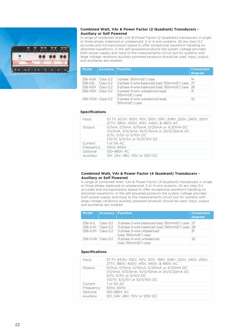
Combined Watt, VAr & Power Factor (2 Quadrant) Transducers -Auxiliary or Self PoweredA range of combined Watt, VAr & Power Factor (2 Quadrant) transducers in singleor three-phase, balanced or unbalanced, 3 or 4-wire systems. All are class 0.2accurate and microprocessor based to offer exceptional waveform handling ondistorted waveforms. In the self powered products the system voltage providesboth power supply and input to the measurements circuit but for systems withlarge voltage variations auxiliary powered products should be used. Input, outputand auxiliaries are isolated.
Input: 57.7V, 63.5V, 100V, 110V, 120V, 139V, 208V, 220V, 240V, 250V,277V, 380V, 400V, 415V, 440V, & 480V AC
Output: 0/1mA, 0/5mA, 0/10mA, 0/20mA or 4/20mA DC1/0/1mA, 5/0/5mA, 10/0/10mA or 20/0/20mA DC0/1V, 0/5V or 0/10V DC1/0/1V, 5/0/5V or 10/0/10V DC
Current: 1 or 5A ACFrequency: 50Hz, 60Hz Optional 100-480V AC Auxiliary: 12V, 24V, 48V, 110V or 125V DC
Specifications
Combined Watt, VAr & Power Factor (4 Quadrant) Transducers -Auxiliary or Self PoweredA range of combined Watt, VAr & Power Factor (4 Quadrant) transducers in singleor three-phase, balanced or unbalanced, 3 or 4-wire systems. All are class 0.2accurate and microprocessor based to offer exceptional waveform handling ondistorted waveforms. In the self powered products the system voltage providesboth power supply and input to the measurements circuit but for systems withlarge voltage variations auxiliary powered products should be used. Input, outputand auxiliaries are isolated.
Input: 57.7V, 63.5V, 100V, 110V, 120V, 139V, 208V, 220V, 240V, 250V,277V, 380V, 400V, 415V, 440V, & 480V AC
Output: 0/1mA, 0/5mA, 0/10mA, 0/20mA or 4/20mA DC1/0/1mA, 5/0/5mA, 10/0/10mA or 20/0/20mA DC0/1V, 0/5V or 0/10V DC1/0/1V, 5/0/5V or 10/0/10V DC
Current: 1 or 5A ACFrequency: 50Hz, 60Hz Optional 100-480V AC Auxiliary: 12V, 24V, 48V, 110V or 125V DC
Specifications
Model Accuracy Function Connectiondiagram
256-XGK Class 0.2 1-phase, 150mm(6") case 14256-XSL Class 0.2 3-phase 3-wire balanced load, 150mm(6") case 27256-XSH Class 0.2 3-phase 4-wire balanced load, 150mm(6") case 28256-XSM Class 0.2 3-phase 3-wire unbalanced load, 31
150mm(6") case256-XSW Class 0.2 3-phase 4-wire unbalanced load, 32
150mm(6") case
Model Accuracy Function Connectiondiagram
256-XJL Class 0.2 3-phase 3-wire balanced load, 150mm(6") case 27256-XJH Class 0.2 3-phase 4-wire balanced load, 150mm(6") case 28256-XJM Class 0.2 3-phase 3-wire unbalanced 31
load, 150mm(6") case256-XJW Class 0.2 3-phase 4-wire unbalanced 32
load, 150mm(6") case

23
Model Accuracy Function Connectiondiagram
256-TTA Class 0.5 DC current, 150mm(6") case 18256-TTM Class 0.5 DC millivolts, 150mm(6") case 18256-TTV Class 0.5 DC voltage, 150mm(6") case 18
Model Accuracy Function Connectiondiagram
256-TTC Class 0.5 Type T thermocouple, 150mm(6") case 18256-TTF Class 0.5 Type J thermocouple, 150mm(6") case 18256-TTN Class 0.5 Type K thermocouple, 150mm(6") case 18
DC/DC Transducers - Auxiliary PoweredA range of DC/DC transducers that provide an output directly proportional to theinput. Suitable for data acquisition and data control monitoring. Input, output andauxiliaries are isolated.
Input: DC current: 200µA to 10A DCDC millivolts: 10mV to 2V DCDC voltage: 2V to 600V DC
Output: 0/1mA, 0/5mA, 0/10mA, 0/20mA or 4/20mA DC1/0/1mA, 5/0/5mA, 10/0/10mA or 20/0/20mA DC0/1V, 0/5V or 0/10V DC1/0/1V, 5/0/5V or 10/0/10V DC
Current: 1 or 5A ACOptional 100-480V AC Auxiliary: 12V, 24V, 48V, 110V or 125V DC
Specifications
Thermocouple (Temperature) Transducers - Auxiliary PoweredA range of transducers for Type T, J & K Thermocouples that provide an outputdirectly proportional to the input. All models incorporate cold junctioncompensation for all base metal thermocouples and thermocouple breakprotection. Input, output and auxiliaries are isolated.
Input: Type T: 0°C to 400°CType J: 0°C to 700°CType K: 0°C to 1200°C
Output: 0/1mA, 0/5mA, 0/10mA, 0/20mA or 4/20mA DC1/0/1mA, 5/0/5mA, 10/0/10mA or 20/0/20mA DC0/1V, 0/5V or 0/10V DC1/0/1V, 5/0/5V or 10/0/10V DC
Current: 1 or 5A ACOptional 100-480V AC Auxiliary: 12V, 24V, 48V, 110V or 125V DC
Specifications
DC/DC Transducers
Thermocouple Transducers

24
Tap Position Transducer - Auxiliary PoweredFor accurate remote indication of tap position selection on a high voltagetransformer. The variable tap position voltage is monitored, and a DC outputproduced which is proportional to the tap position. Input, output and auxiliaries are isolated.
Input: 1K to 20K5-50 taps at 400 each10-50 taps at 30 each
Output: 0/1mA, 0/5mA, 0/10mA, 0/20mA or 4/20mA DCCurrent: 1 or 5A ACOptional 100-480V AC Auxiliary: 12V, 24V, 48V, 110V or 125V DC
Specifications
Resistance Transducer - Auxiliary PoweredA simple and convenient way of measuring and transmitting temperature values inthe form of a load independent DC signal. Transmitters detect varying resistancedue to temperature change at the RTD (Resistance Temperature Detector).Designed for platinum (Pt.100), copper (Cu 10) or nickel (Ni100) RTDs. Input,output and auxiliaries are isolated.
Input: 100 Platinum (Pt 100)10 Copper (Cu 10)100 Nickel (Ni 100)
Output: 0/1mA, 0/5mA, 0/10mA, 0/20mA or 4/20mA DCCurrent: 1 or 5A ACOptional 100-480V AC Auxiliary: 12V, 24V, 48V, 110V or 125V DC
Specifications
Tap Position Transducers
Resistance Transducers
Model Accuracy Function Connectiondiagram
253-TRT Class 0.5 Tap position, 75mm(3") case 12
Model Accuracy Function Connectiondiagram
253-TRR Class 0.5 Resistance, 75mm(3") case 17
Single Frequency Transducers - Self Powered, 1 DC The signal isolator is designed for use in signal transmission and processingapplications to prevent noise and interference caused by ground loops betweensignal source and the measuring device. The isolator provides galvanic high voltageisolation between the source and measuring device.
Specifications
Single Isolator
Model Accuracy Function Connectiondiagram
250-ISA Class 0.2 Signal Isolator 5
Input/output ratio: 1 to 1Max Input/output: 20mA DCIsolation: 660V AC, 930V DC continuosLoad range: 0-500 ohms @ 20mA DCOutput voltage: 1 out x R Load limited to 15VInput voltage: Typically 1 x (load + 200) limited to 18V

25
Model A A B Bmm inches mm inches
250 22.5 0.88 - -252 55 2.17 - -253 75 2.96 60 2.36256 150 5.90 135 5.31
8 SCREW
TERMINALS
M3.5
2 TERMINAL
COVERS
LID CASE VIEW WITH TERMINAL
COVER REMOVED FOR
CLARITY
22.5
(0.89") 90.0 (3.54")
11.25
(0.445")
80.0 (3.15")
89.0 (3.50")
75.0 (2.95")
35.0
5.0
(0.20")
81.0 (3.19")
53.5 (2.11")
Dimensions
Model 252
Model 250
RELEASE CLIP
RELEASE CLIP ADAPTOR FOR MODEL 252
REAR VIEW SHOWING PANEL
MOUNTING HOLES
99.0 (3.90")
55.0
(2.17") 35(1.38")
73(2.87")
112(4.41")
55(2.17")
15(0.59")
35(1.38")
A
70(2.76")
35(1.38")
112(4.41") B
50(M4)
60(M5)
70
Model 253, 256
Paladin Transducers 250 Series
The signal isolator is designed for use in signal transmission and processingapplications to prevent noise and interference caused by ground loops betweensignal source and the measuring device. The isolator provides galvanic highvoltage isolation between the source and measuring device.

26
Connection Diagrams
Type 252-XAA, Type 253-TAASingle-phase Current, Self Powered –Diagram 1
Type 252-XAS/XAR/XAL,Type 253-TAL/TARSingle-phase Current – Diagram 6
Type 250-ISASignal Isolator – Diagram 5
Type 256-XAS/XAR, Type 256-TAS, TAL, TAR3 Ø Current, 3 Outputs – Diagram 2
Type 256-XLKVoltage, Current and Frequency, 3 Outputs – Diagram 9
Type 252-XVS, XVZ, XVR, XVL, XHL, XHSType 253-TVL, TVR, TVZSingle-phase Voltage – Diagram 15
Type 256-XVS/XVR/XVZ/XVL3 Ø 4W Voltage, 3 Outputs – Diagram 16
Type 256-XWK/XXK/XYK/XDK/XEK/XGK/XFS/XFA/XPS/XPAType 256-TWK/TXK/TYKSingle-phase, Watts or VArs or VA orPhase Angle or Power Factor, Wattand VAr: Watt, VAr and VA: Watt,VAr and Power Factor.One Output – Diagram 14
Type 253-TRTTap Position Diagram 12
Type 252-XVA & Type 253-TVA Single-phase Voltage Self Powered
Type 252-XHA, 253-THZFrequency – Diagram 10
Type 256-TVL, TVR, TVS, TVWType 256-XVU, XVW, XVY, XVX3 x 1Ø Voltages 3 Outputs – Diagram 11

27
Type 256-XWL/XXL/XYL/XFW/XPW/XPG/XFGType 256-TWL/TPB/TFB/TFE3 Ø 3W Balanced Load, Watts or VArs orVA or Phase Angle or Power Factor.One Output – Diagram 19
Type 256-TTA/M/V/F/C/NDC/DC Transducer and TemperatureDiagram 18
Type 253-TRRTemperature Transmitter – Diagram 17
Type 256-XWM/XXM/XYM/XZM/XFU/XFC/XPU/XPCType 256-TWM/TXM/TYM3 Ø 3W Unbalanced Load, Watts or VArsor VA or Phase Angle or Power Factor.One Output – Diagram 20
Type 256-XWW/XXW/XYW/XZW/XFT/XFB/XPT/XPB3 Ø 4W Unbalanced Load, 3 Elements,Watts or VArs or VA or Phase Angle orPower Factor.One Output – Diagram 21
Type 256-XDM3 Ø 3W Unbalanced Load, Wattand VAr, 2 Outputs – Diagram 22
Type 256-XDW3 Ø 4W Unbalanced Load, 3Elements, Watt and VAr, 2Outputs – Diagram 23
Type 256-XWH/XXH/XYH/XFV/XFD/XPV/XPDType 256-TWH/TXH/TYH3 Ø 4W Balanced Load, Watt, VArand VA or Phase Angle or PowerFactor. 1 Output – Diagram 24
Type 256-XDL3 Ø 3W Balanced Load, Watt andVAr, 2 Outputs – Diagram 25

28
Type 256-XDH
3 Ø 4W Balanced Load, Watt and VAr, 2 Outputs – Diagram 26
Type 256-XRL/XSL/XJL3 Ø 3W Balanced Load, Watt, VAr and VA: Watt, VAr and Power Factor. 3 Outputs – Diagram 27
Type 256-XRH/XSH/XJH3 Ø 4W Balanced Load, Watt, VAr and VA: Watt, VAr and Power Factor. 3 Outputs – Diagram 28
Type 256-XRM/XSM/XJM3 Ø 3W Unbalanced Load, Watt, VAr and VA: Watt, VAr and PowerFactor. 3 Outputs – Diagram 31
Type 256-XWE/XXE/XYE/XFE/XFF/XPE/XPF3 Ø 4W Unbalanced Load, Watt, VAr and VA or Phase Angle orPower Factor. 3 Outputs – Diagram 29
Type 256-TWN/TXP/TYN3 Ø 4W Unbalanced Load, Watt or VAr, or VA – Diagram 35
Type 256-TWE/TXG3 Phase 3-wire Balanced Load, Watt,VAr or Phase Angle – Diagram 34
Type 256-XRW/XSW/XJW
3 Ø 4W Unbalanced Load, 3Elements, Watt, VAr and VA: Watt,VAr and Power Factor. 3 Outputs –Diagram 32
29
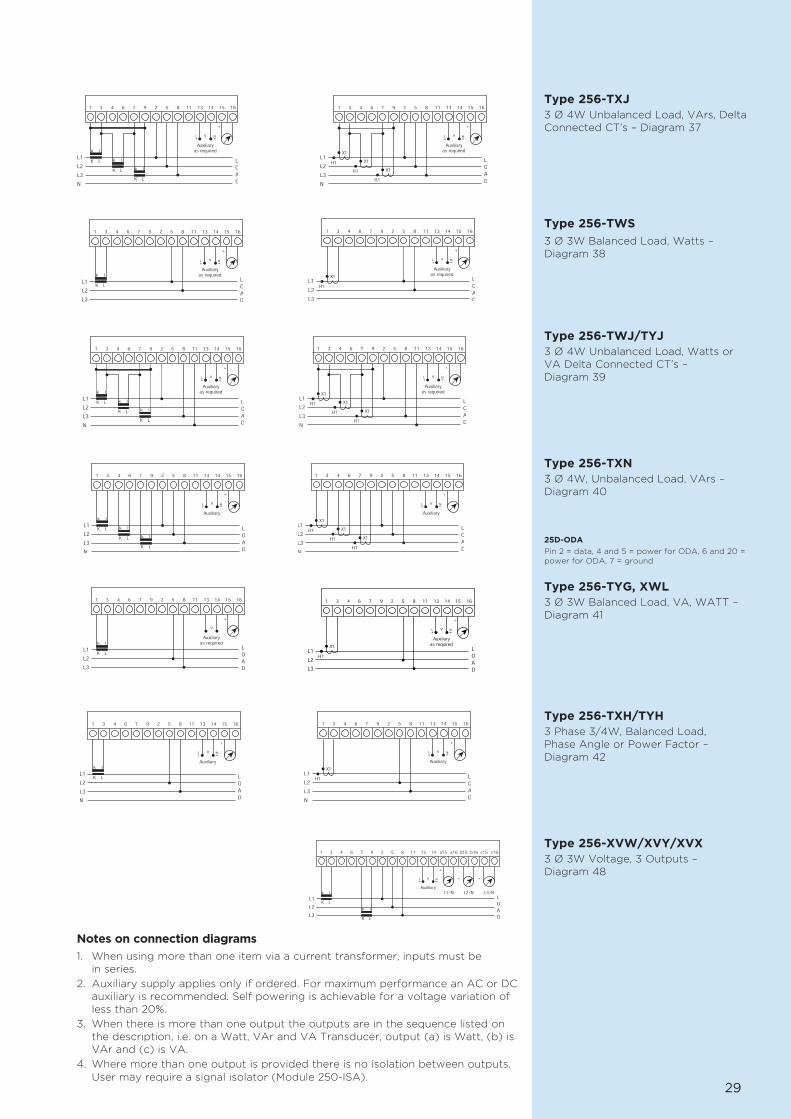
Type 256-TXJ3 Ø 4W Unbalanced Load, VArs, DeltaConnected CT’s – Diagram 37
25D-ODA
Pin 2 = data, 4 and 5 = power for ODA, 6 and 20 =power for ODA, 7 = ground
Type 256-TWS
3 Ø 3W Balanced Load, Watts –Diagram 38
Type 256-TWJ/TYJ3 Ø 4W Unbalanced Load, Watts orVA Delta Connected CT’s –Diagram 39
Type 256-TXN3 Ø 4W, Unbalanced Load, VArs –Diagram 40
Type 256-TYG, XWL3 Ø 3W Balanced Load, VA, WATT –Diagram 41
Type 256-TXH/TYH3 Phase 3/4W, Balanced Load,Phase Angle or Power Factor –Diagram 42
Type 256-XVW/XVY/XVX3 Ø 3W Voltage, 3 Outputs –Diagram 48
Notes on connection diagrams
1. When using more than one item via a current transformer, inputs must be in series.
2. Auxiliary supply applies only if ordered. For maximum performance an AC or DCauxiliary is recommended. Self powering is achievable for a voltage variation ofless than 20%.
3. When there is more than one output the outputs are in the sequence listed onthe description, i.e. on a Watt, VAr and VA Transducer, output (a) is Watt, (b) isVAr and (c) is VA.
4. Where more than one output is provided there is no isolation between outputs.User may require a signal isolator (Module 250-ISA).

About TE Connectivity
TE Connectivity is a global, $14 billion company that designs and manufactures over500,000 products that connect and protect the flow of power and data inside theproducts that touch every aspect of our lives. Our nearly 100,000 employeespartner with customers in virtually every industry – from consumer electronics,energy and healthcare, to automotive, aerospace and communication networks –enabling smarter, faster, better technologies to connect products to possibilities.
© 2013 Tyco Electronics UK Ltd CI-EPP-2041-12/12-TRANSDWhile TE Connectivity (TE) has made every reasonable effort to ensure the accuracy of the information in this catalogue, TE does not guarantee that it is error-free, nor does TE make any
other representation, warranty or guarantee that the information is accurate, correct, reliable or current. TE reserves the right to make any adjustments to the information contained hereinat any time without notice. TE expressly disclaims all implied warranties regarding the information contained herein, including, but not limited to, any implied warranties of merchantabilityor fitness for a particular purpose. The dimensions in this catalogue are for reference purposes only and are subject to change without notice. Specifications are subject to change withoutnotice. Consult TE for the latest dimensions and design specifications. TE Connectivity and TE connectivity (logo) are trademarks. CROMPTON is a trademarks of Crompton Parkinson Limitedand is used under licence. Other products or company names mentioned herein may be trademarks of their respective owners.
TE Energy – innovative and economical solutions for the electrical power industry: cable accessories, connectors & fittings,insulators & insulation, surge arresters, switching equipment, street lighting, power measurement and control.
Tyco Electronics UK LtdTE EnergyFreebournes RoadWitham, Essex CM8 3AH
Phone: +44 (0)870 870 7500Fax: +44 (0)870 240 5287Email: [email protected]
crompton-instruments.comenergy.te.com
Registered office:Faraday Road, DorcanSwindon, SN3 5HHReg. no. 550 926