Embed Size (px)
Citation preview

www.microchip.com Microcontrollers•DigitalSignalControllers•Analog•SerialEEPROMs
INTHISISSUEPAGE 1New C Programming Class offered at Microchips RTCs
PAGE 2Join Us for Training Sessions at ESC Boston
PAGE 3Op Amps & PGAs
PAGE 4An Overview of Embedded Systems
PAGE 5 FREE Mechatronics Expo
PAGE 6Add Intelligence to Your Lighting Design
PAGE 7EMC Resources
PAGE 8Use the MPLAB® C30 Compiler to Interface Serial EEPROMs with dsPIC33F Devices
PAGE 9PWM Generator Tips ‘n Tricks
PAGE 10Using the Adjustable Voltage Regulator on the PICDEM™ HPC Explorer Board
PAGE 11ICwiki: In-circuit Programming
PAGE 12Microchip Around Town
PAGE 13Microchip’s Design Partner Program
Microchip is Hiring
PAGE 14What’s New in Microchip Literature?
PAGE 15Web Site Highlights
Microchip Technology Makes Learning to Program in the C Language Easy & Affordable!Join us at your local Regional Training Center for our newest class… 101 ECP: Embedded C Programming: Introduction to the C Programming Language
Now you don’t have to spend weeks learning to read and write code for a variety of design platforms! Learn the C language from the ground up – from a non-hardware specific point of view – to focus on the various elements of the C language itself.
This two-day course introduces the C programming language (as specified by the ANSI C89 standard) in the context of embedded systems. The course is accompanied by a series of hands-on exercises that are designed to reinforce the C programming fundamentals using Microchip’s free MPLAB® SIM software simulator. Skills learned in this class will be applicable to any ANSI C compiler.
Microchip makes it affordable to get started with three price options!
Option 1: $399.00 USD - Includes CD and instruction
Option 2: $699.00 USD - Includes MPLAB® C18 C Compiler (SW006011), CD and instruction
Option 3: $999.00 USD - Includes MPLAB® C30 C Compiler (SW006012), CD, and instruction
Formoreinformationortoregister,contactyourlocalMicrochipRegionalTrainingCenterorvisitusatwww.microchip.com/RTC

MICROCHIPTECHNOLOGY’SmicroSOLUTIONSeNEWSLETTER-September2007
www.microchip.com Microcontrollers•DigitalSignalControllers•Analog•SerialEEPROMs 2
RETURNTOFRONTPAGEToregisterforourtrainingsessions,pleasevisitwww.microchip.com/ESC
Introduction to Digital Power Converter Design Using the dsPIC® Digital SignalController Family forSMPS:This class introduces the design and implementation of a digital mode synchronous buck DC/DC converter using the dsPIC DSC family for SMPS. The SMPS PWM, ADC, and analog comparator modules, combined with the DSC processor, enables the creation of power conversion circuits utilizing digital control loops. This class discusses the SMPS peripherals and their use in an actual circuit, along with their integration with the control loop software.
MPLAB®REAL ICE™In-CircuitEmulatorDemonstration:This class demonstrates the features and advantages of Microchip’s next generation high-speed, MPLAB REAL ICE emulation system, which features real-time, full speed emulation and fast programming of Microchip Flash MCU and DSC devices. Real-time variable watch and trace analysis are just two of the many features, all for under $500.
EmbeddedUSBSolutionsFromMicrochipThis class presents Microchip’s cost-effective and easy-to-use USB products, software and development tools, and features the PIC18F microcontrollers with free USB stacks. Learn how to easily add USB capability to your embedded design.
Mechatronics Defined: As technology advances, designs that were once purely mechanical are now best done with electronics or a combination of both. This class explores what mechatronics is, the role PIC® microcontrollers and the benefits of mechatronic designs verses mechanical designs. Mechatronics is broken down at the system level so that you can study the components necessary for your design.
ZigBee™andMiWi™Protocols: Discussion of ZigBee™ protocol and Microchip stack capabilities as well as an introduction to Microchip’s own wireless MiWi™ protocol. The MiWi protocol is available free of charge and is ideal for users not needing full protocol interoperability.
EthernetSolutionsfromMicrochip:Ethernet’s capabilities and ubiquitous deployment make it unrivaled among communications standards. This class presents Microchip’s cost-effective and easy-to-use Ethernet products, software and development tools including the 28-pin stand-alone Ethernet controller, a family of PIC18F microcontrollers with Ethernet peripheral and free TCP/IP stack. Learn how to add Ethernet capability to your embedded design.
16-bitMicrocontrollerandDigitalSignalControllerProductFamilyOverview:If you’re an embedded designer looking for high-performance products coupled with a solid migration strategy, this class shows you the benefits of using one software development environment to program everything from your simplest 6-pin, 8-bit microcontroller to the industry’s highest performing 16-bit microcontrollers and digital signal controllers. Technical experts will showcase the architectural and peripheral features of Microchip’s new 16-bit microcontroller and digital signal controller families.
AnalogSensorConditioninginEmbeddedSystems:Most sensor circuits require some analog signal conditioning before conversion to digital. This class provides background information on several types of sensors and sensor conditioning circuits, including active filters. Three common sensors, thermistor (temperature), photodiode (light) and capacitance (humidity) and their conditioning circuits, are detailed. A demonstration of filter designs generated by Microchip’s FilterLab® software is included.
Microchip is excited to be back at ESC Boston this year with a variety of training sessions available daily at the Microchip booth.
JOIN us for training sessions booth 509!
JOIN us for training sessions booth 509!

MICROCHIPTECHNOLOGY’SmicroSOLUTIONSeNEWSLETTER-September2007
www.microchip.com Microcontrollers•DigitalSignalControllers•Analog•SerialEEPROMs �
RETURNTOFRONTPAGEForfurtherinformationvisitwww.microchip.com/OpAmps
MCP6041
0.7
0.6
0.5
0.4
0.3
0.2
0.1
0.0
0.0 0.5 1.0 1.5 2.0 2.5 3.0 3.5 4.0 4.5 5.0 5.5 6.0 6.5 7.0
Power Supply Voltage (V)
Quie
scent C
urr
ent P
er
Am
plif
ier
(µA
)
TA = 85°C
TA = 25°C
TA = -40°C
Current Sensor
–
MCP6041
+
VDD = 1.4V
IQ = 600 nA (typ.)
I RX
R2
R1
MCP604XandMCP614XKeyFeatures: Low Quiescent Current: 600 nA Amplifier (typ.)Gain Bandwidth Product: 14 kHz (typ), MCP6041
Gain Bandwidth Product: 100 kHz (typ), MCP6141 (G ≥ 10)Wide Supply Voltage Range: 1.4V to 5.5V (max.)
LOWPOWEROPERATIONALAMPLIFIERS CASCADEDOPERATIONALAMPLIFIERS PROGRAMMABLEGAINAMPLIFIERS
MCP62X5KeyFeatures:Chip-Select (CS) Pin for Both AmplifiersSmall 8-pin Packages (PDIP-8, SOIC-8, MSOP-8)Pinout Similar to the Industry Standard for Duals
VDD
(8)
VOUTB
(7)
(4)
VSS
VINA+
(3)
(2)
VINA–
(1)
VOUTA/VINB+
(6)
VINB–
CS(5)
+
–
+
–
Pinout Configuration
ProgrammableGainAmplifiersKeyFeatures:8 Gain Selections: +1, +2, +4, +5, +8, +10, +16 or +32V/VSerial Peripheral Interface (SPI)Low Offset (MCP6S21/2/6/8): ±275 µV (Max.)High Bandwidth: 2 to 12 MHz (typ.)
0%
2%
4%
6%
8%
10%
12%
14%
16%
18%
-0.5
-0.4
-0.3
-0.2
-0.1
0.0
0.1
0.2
0.3
0.4
0.5
DC Gain Error (%)
Perc
en
tag
e o
f O
ccu
rren
ces
420 SamplesG +2?
Sensor 1
VOUT
Sensor 8
MCP6S28
3 PIC®
Microcontroller
Anti-Aliasing
Filter
SPILogic
ADCMUX PGA
>-
3

MICROCHIPTECHNOLOGY’SmicroSOLUTIONSeNEWSLETTER-September2007
www.microchip.com Microcontrollers•DigitalSignalControllers•Analog•SerialEEPROMs 4
RETURNTOFRONTPAGE
An Overview of Embedded Systems
An embedded system is typically a design making use of the power of a microcontroller, like the Microchip PIC® Microcontrollers (MCUs) or dsPIC® Digital Signal Controllers (DSCs). These microcontrollers combine a microprocessor unit (like the Central Processing Unit (CPU) in a desktop PC) with some additional circuits called “peripherals”, plus some additional circuits on the same chip to make a small control module requiring few other external devices. This single device can then be embedded into other electronic and mechanical devices for low-cost digital control.
An example of an embedded system is a smoke detector. Its function is to evaluate signals from a sensor and sound an alarm if the signals indicate the presence of smoke. A small program in the smoke detector either runs in an infinite loop, sampling the signal from the smoke sensor, or lies dormant in a low-power “sleep” mode, being awakened by a signal from the sensor. The program then sounds the alarm. The program would possibly have a few other functions, such as a user test function, and a low battery alert. While a PC with a sensor and audio output could be programmed to do the same function, it would not be a cost-effective solution – nor would it run on a nine-volt battery, unattended for years! Embedded designs use inexpensive microcontrollers to put intelligence into the everyday things in our environment, such as smoke detectors, cameras, cell phones, appliances, automobiles, smart cards and security systems.
Differences Between an Embedded Controller and a PC:
Embedded Controller PC
Dedicated to one specific task Can do many different tasks
Has a single program, which can be made inexpensively to include just enough computing power and hardware to perform a dedicated task.
Runs many different types of programs and can be re-configured to do each task optimally.
Program is usually permanently “burned” into memory when manufactured.
Program is loaded into memory when needed – usually from hard drive.
Has a low-cost microcontroller for its intelligence, with many peripheral circuits on the same chip, and with relatively few external devices.
Has a relatively expensive generalized central processing unit (CPU) at its heart with many other external devices (memory, disk drives, video controllers, network interface circuits, etc.).
Often, an embedded system is an invisible part or sub-module of another product, such as a cordless drill, refrigerator or garage door opener. The controller in these products does a tiny portion of the function of the whole device. The controller adds low-cost intelligence to some of the critical sub-systems in these devices.
Usually, a large system, often part of a network, employed for word processing, spreadsheet calculations, presentations, internet interface, GUI for various PC-based tools.
ComponentsofaMicrocontrollerThe PIC MCU has program memory for the firmware, or coded instructions, to run a program. It also has “file register” memory for storage of variables that the program will need for computation or temporary storage. It also has a number of peripheral device circuits on the same chip.
Some peripheral devices are called I/O ports. I/O ports are pins on the microcontroller that can be driven high or low to send signals, blink lights, drive speakers – just about anything that can be sent through a wire. Often these pins are bidirectional and can also be configured as inputs allowing the program to respond to an external switch, sensor or to communicate with some external device.
In order to design such a system, it must be decided which peripherals are needed for an application. Analog-to-digital converters allow microcontrollers to connect to sensors and receive changing voltage levels. Serial communication peripherals allow you to stream communications over a few wires to another microcontroller, to a local network or to the internet. Peripherals on the PIC MCU called “timers” accurately measure signal events and generate and capture communications signals, produce precise waveforms, and even automatically reset the microcontroller if it gets “hung” or lost due to a power glitch or hardware malfunction. Other peripherals detect if the external power is dipping below minimal levels so the microcontroller can store critical information and safely shut down before power is completely lost.
The peripherals and the amount of memory an application needs to run a program largely determines which PIC MCU to use. Other factors might include the power consumed by the microcontroller and its “form factor,” i.e., the size and characteristics of the physical package that must reside on the target design.
Interested in adding intelligence to your next design? Learn how with PIC® microcontrollers!
Tolearnmoreaboutgettingstartedinembeddeddesign,visitwww.microchip.com/gettingstarted

MICROCHIPTECHNOLOGY’SmicroSOLUTIONSeNEWSLETTER-September2007
www.microchip.com Microcontrollers•DigitalSignalControllers•Analog•SerialEEPROMs 5
RETURNTOFRONTPAGE
AttendeesWill...• Meet other skilled engineers from diverse backgrounds who
are looking to expand their understanding of Mechatronics• Learn best practices in applying Mechatronics design
within your organization • Hear from the experts of different disciplines who will share
the value of tighter integration
KeynotePresentationKevin Craig, Ph.D., Professor of Mechanical Engineering, Rennsselaer Polytechnic Institute
Professor Craig explains the essential elements of mechatronics and tells why this design approach is essential for engineering success in countless products.
Expo:Ballroom foyer for tradeshow booths, accessible to attendees at all times. A perfect opportunity for you to get “face to face” with technology exports.
SeminarSeries:Essential Mechatronics Tools for Efficient DesignThis session takes an in-depth look at a new simulation-based approach to designing machines. Learn how to link control and 3-D CAD tools to simulate machine operation, size motors and tune control algorithms.
Linking Systems Engineering to the Product Life CycleLearn how to integrate systems engineering with the entire product development cycle, including mechatronics design, ergonomics, software, testing, manufacturing, cost controls, maintenance issues and much more.
Small and Practical Mechatronics SystemsWhile you may think of mechatronics in terms of elaborate factory automation systems, the same design concepts apply to countless products, from household appliances to medical devices. A major key to many of these designs: powerful but compact embedded control.
Mechatronics Design in Industrial AutomationHear examples of how mechatronic integrative design is helping factory automation OEMs improve their machines and get them to market faster. One of the secrets: complete machine simulation.
ExpoWrap-upPanelDiscussion:Real-world Mechatronics SolutionsA panel discussion featuring representatives from National Instruments, Siemens, UGS and Microchip, together with engineers from several New England companies that have implemented successful mechatronics designs.
Date: October 9, 2007
Time: Registration/breakfast at 7:30 AM A keynote address starts the day at 8:30 AM Breakout sessions then run throughout the day Concluding with a cocktail reception at 4:30 PM
Place: Burlington Marriott, One Mall Road, Route 128 & 3A, Burlington, Massachusetts 01803.
REGISTER TODAY AT www.designnews.com/mechexpo

MICROCHIPTECHNOLOGY’SmicroSOLUTIONSeNEWSLETTER-September2007
www.microchip.com Microcontrollers•DigitalSignalControllers•Analog•SerialEEPROMs 6
RETURNTOFRONTPAGE
Learn How to Add Intelligence to Your Lighting ApplicationsLEDs are no longer used just for providing the pretty red and green indicator lights on electronic equipment. Advances in technology have allowed LEDs to be used as practical sources of illumination. The primary benefits of LEDs are long life, durability and efficiency. When driven properly, a power LED can last tens of thousands of hours without a degradation of light output. The typical efficacy of a power LED, measured in lumens per watt, is 40- 80. This is several times greater than incandescent light sources and is only exceeded by fluorescent light sources. Since the LED is a solid-state device, it can withstand shock and vibration that would damage a filament bulb.
LEDApplicationsThe benefits of LED lighting are helpful in many types of lighting applications:• Automotive and aircraft cabin and instrument panel lighting
• Architectural emergency exit lighting
• Architectural color effect lighting
• Industrial and outdoor lighting
• Traffic and railway signals
• Automotive brake lights
• Dot matrix signs and video displays
• LCD display backlighting
• Personal flashlights
• Medical instrument and tool lighting
• Digital camera flash and video light
EfficientLEDControlLEDs must be driven with a source of constant current. Most LEDs have a specified current level that will achieve the maximum brightness for that LED without premature failures. An LED could be driven with a linear voltage regulator configured as a constant current source. However, this approach is not practical for higher power LEDs due to power dissipation in the regulator circuit. A switch-mode power supply (SMPS) provides a much more efficient solution to drive the LED. An LED will have a forward voltage drop across its terminals for a given current drive level. The power supply voltage and the LED forward voltage characteristics determine the SMPS topology that is required. Multiple LEDs can be connected in series to increase the forward voltage drop at the chosen drive current level.
The SMPS circuit topologies adopted to regulate current in LED lighting applications are the same used to control voltage in a power supply application. Each type of SMPS topology has its advantages and disadvantages as presented in the table below.
DrivingLEDswithaChargePumpA charge pump power supply does not have inductors that are required in other SMPS topologies. This provides a more compact and less expensive circuit. The downside is that charge pumps cannot supply large amounts of current compared to the other topologies. Charge pump circuits are most useful for backlighting applications. Common applications include PCs, LCD displays and automotive instrumentation.
DrivingLEDswithaBoostRegulatorA boost regulator topology is used when the output voltage of the converter must be equal to or greater than the input voltage. A boost regulator is useful for driving a chain of LEDs connected in series. It is beneficial to
drive multiple LEDs in series. This ensures that all LEDs receive the same amount of current and will have the same brightness level using a coupled inductor in the boost circuit to reduce the switching voltage requirements of the MOSFET switch.
Formoreinformation,visithttp://ww1.microchip.com/downloads/en/DeviceDoc/010�6b.pdf

MICROCHIPTECHNOLOGY’SmicroSOLUTIONSeNEWSLETTER-September2007
www.microchip.com Microcontrollers•DigitalSignalControllers•Analog•SerialEEPROMs 7
RETURNTOFRONTPAGE
Is Electromagnetic Compatibility (EMC) a Concern?Over the last few years, Electromagnetic Compatibility (EMC) has become a major concern for many engineers. Generally speaking, EMC is the ability of a system to operate in an environment without disturbing anything else in that environment, including itself.
With the proliferation of electronic equipment, electromagnetic noise has reached critical levels. Resolving EMC ensures that the product will be reliable and safe wherever it is used. No one wants their ABS disturbed by a mobile phone, or their freezer to stop running when a power tool is plugged in.
Government and industry regulators have put EMC qualifications in place – as Europe has with required CE certification. EMC requirements vary from country to country; however, many countries have adopted EMC requirements based on IEC (International ElectroTechnical Commission) guidance (www.iec.ch).
From a designer point of view, EMC is considered as both emission and immunity. EMC can be radiated (through the air) or conducted (through a physical medium). Robustness can be defined as the degree to which a system or component can function correctly in the presence of invalid inputs or stressful environment conditions.
Today, a product should integrate more and more features at a lower cost, with shorter design cycles and higher reliability. Products must comply with stringent and ever changing regulations and work in harsh environments without adding overhead costs. In addition, reliability and predictably are still critical. This can be especially challenging for multi-board and multi-sensor applications.
Are you looking for cost-effective, robust solutions? Are you challenged to deliver products that integrate additional electronics and run at higher frequencies and lower voltages? Indeed, a robust product should simplify the design of the application by saving additional components, such as filters, shortening the test and qualification time, avoiding costly rework or production slips, and achieving a lower field failure rate.
Addressing EMC at an early stage of the design can help you avoid costly last-minute design patches to meet robustness targets. At a system level, addressing the PCB layout and component placement will help to handle the high frequency spectrum, where traces and wires start to look like antennas.
Since most power supplies are connected to the main, the application also faces external transient and other power perturbations (sags, outstage, etc.) in addition to internal ones due to motors or relays.
The need for lower emission and higher levels of immunity is as important as features and performance. Robustness is now a significant attribute of quality and a decisive criterion when choosing a device.
Long-termCommitmenttoRobustnessThe importance of system robustness is well understood at Microchip. With our strategic focus of supplying silicon for embedded control applications, Microchip’s goal is to create products with improved robustness. As a result, our PIC® microcontrollers, dsPIC® digital signal controllers, memories and analog and interface products perform predictably in harsh and noise-sensitive environments.
Microchip has created world-class Flash and data EEPROM memory products with industry-leading endurance – up to 1 million erase/write operations, and data retention up to 100 years, specified over the entire operational temperature and voltage ranges for its products. Microchip also offers world-class ESD protection on every part.
To help engineers design robust applications, Microchip integrates several relevant peripherals:
WDT (WatchDog Timer): Having its own separate RC oscillator, the WDT is a timer capable of running during active or Sleep mode. Its function is to reset the microcontroller in case of an unanticipated event.
POR (Power On Reset): Internal circuitry ensures that VDD has achieved a minimum voltage level to operate properly.
BOR (Brown Out Reset): Ensures reliable operation by resetting the microcontroller when VDD goes below normal operating voltage.
Internal Oscillator: Using the internal oscillator is the best way to avoid crystal harmonics and leading to lower emissions.
Fail Safe Clock: The fail safe clock monitor allows the microcontroller to continue operation in the event of an external oscillator failure, by automatically switching to the internal oscillator.
Software Programmable WDT or BOR: Allows reliable low power operation.
• EMC Web Page: www.microchip.com/EMC
• Web Seminars Page: www.microchip.com/Webinars – EMC Part 1: Introduction to Electro Magnetic Compatibility (EMC) – EMC Part 2: What is Electrostatic Discharge (ESD)? – EMC Part 3: What are Electrical Fast Transients (EFT)? • Application Notes: www.microchip.com/AppNotes – AN595 - Improving the Susceptibility of an Application to ESD – AN688 - Layout Tips for 12-Bit A/D Converter Application – AN823 - Analog Design in a Digital World Using Mixed Signal Controllers
EM
C R
ES
OU
RC
ES
MICROCHIPTECHNOLOGY’SmicroSOLUTIONSeNEWSLETTER-September2007
www.microchip.com Microcontrollers•DigitalSignalControllers•Analog•SerialEEPROMs �
RETURNTOFRONTPAGE
Application Note AN1100: Using the MPLAB® C30 Compiler to Interface Serial EEPROMs with dsPIC33F
Author: Martin Bowman, Microchip Technology Inc.
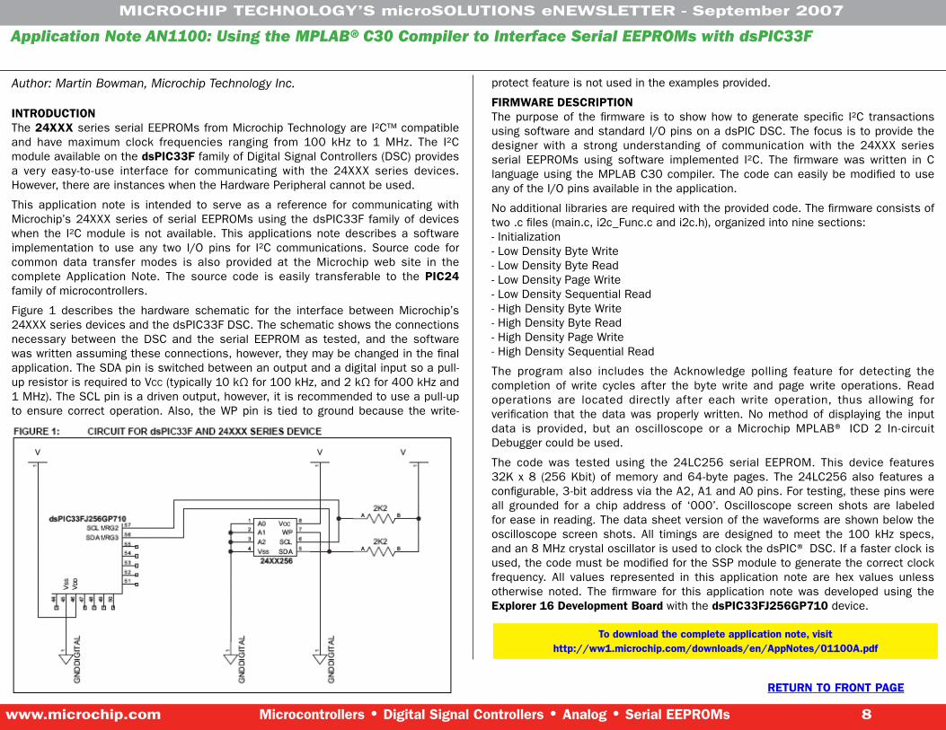
INTRODUCTIONThe 24XXX series serial EEPROMs from Microchip Technology are I²C™ compatible and have maximum clock frequencies ranging from 100 kHz to 1 MHz. The I²C module available on the dsPIC��F family of Digital Signal Controllers (DSC) provides a very easy-to-use interface for communicating with the 24XXX series devices. However, there are instances when the Hardware Peripheral cannot be used.
This application note is intended to serve as a reference for communicating with Microchip’s 24XXX series of serial EEPROMs using the dsPIC33F family of devices when the I²C module is not available. This applications note describes a software implementation to use any two I/O pins for I²C communications. Source code for common data transfer modes is also provided at the Microchip web site in the complete Application Note. The source code is easily transferable to the PIC24 family of microcontrollers.
Figure 1 describes the hardware schematic for the interface between Microchip’s 24XXX series devices and the dsPIC33F DSC. The schematic shows the connections necessary between the DSC and the serial EEPROM as tested, and the software was written assuming these connections, however, they may be changed in the final application. The SDA pin is switched between an output and a digital input so a pull-up resistor is required to VCC (typically 10 kΩ for 100 kHz, and 2 kΩ for 400 kHz and 1 MHz). The SCL pin is a driven output, however, it is recommended to use a pull-up to ensure correct operation. Also, the WP pin is tied to ground because the write-
protect feature is not used in the examples provided.
FIRMWAREDESCRIPTIONThe purpose of the firmware is to show how to generate specific I²C transactions using software and standard I/O pins on a dsPIC DSC. The focus is to provide the designer with a strong understanding of communication with the 24XXX series serial EEPROMs using software implemented I²C. The firmware was written in C language using the MPLAB C30 compiler. The code can easily be modified to use any of the I/O pins available in the application.
No additional libraries are required with the provided code. The firmware consists of two .c files (main.c, i2c_Func.c and i2c.h), organized into nine sections:- Initialization- Low Density Byte Write- Low Density Byte Read- Low Density Page Write- Low Density Sequential Read- High Density Byte Write- High Density Byte Read- High Density Page Write- High Density Sequential Read
The program also includes the Acknowledge polling feature for detecting the completion of write cycles after the byte write and page write operations. Read operations are located directly after each write operation, thus allowing for verification that the data was properly written. No method of displaying the input data is provided, but an oscilloscope or a Microchip MPLAB® ICD 2 In-circuit Debugger could be used.
The code was tested using the 24LC256 serial EEPROM. This device features 32K x 8 (256 Kbit) of memory and 64-byte pages. The 24LC256 also features a configurable, 3-bit address via the A2, A1 and A0 pins. For testing, these pins were all grounded for a chip address of ‘000’. Oscilloscope screen shots are labeled for ease in reading. The data sheet version of the waveforms are shown below the oscilloscope screen shots. All timings are designed to meet the 100 kHz specs, and an 8 MHz crystal oscillator is used to clock the dsPIC® DSC. If a faster clock is used, the code must be modified for the SSP module to generate the correct clock frequency. All values represented in this application note are hex values unless otherwise noted. The firmware for this application note was developed using the Explorer16DevelopmentBoardwith the dsPIC��FJ256GP710 device.
Todownloadthecompleteapplicationnote,visithttp://ww1.microchip.com/downloads/en/AppNotes/01100A.pdf

MICROCHIPTECHNOLOGY’SmicroSOLUTIONSeNEWSLETTER-September2007
www.microchip.com Microcontrollers•DigitalSignalControllers•Analog•SerialEEPROMs �
RETURNTOFRONTPAGE
Interested in this Topic?Keith Curtis is scheduled to present “Mixed-Signal Peripherals Promote Intelligent Power Conversion “at the Portable Design Conference, Oct. 3-4, 2007 at the Santa Clara Convention Center in Santa Clara, CA.
Battery voltage is often incompatible with most, if not all, electronic systems in portable designs. Additionally, to efficiently manage the energy available in the battery, it is often necessary to selectively power different systems in the design based upon the current mode of operation. These requirements mean that an intelligent power conversion and control system are needed, which will compete for space in an already cramped area. Fortunately, mixed-signal peripherals available in the latest generations of microcontrollers provide cost- and real estate-sensitive solutions to this problem. For example, on-chip Pulse Width Modulation (PWM) generators with automatic analog shutdown comparators. And even switching power-supply peripherals make it possible to combine both power conversion and control functions into a single piece of silicon. This synergy of functions enables designers to not only build smaller, more efficient power-conversion and power-control systems but the level of integration between the peripherals and the microcontroller allow the actual topology of the conversion system to change in response to system requirements. This presentation will examine some capabilities of such on-chip peripherals with several design examples. Both capacitive and inductive conversion systems will be examined, as well a topology switching system for handling both charging and power conversion for a battery system.
PIC® Microcontroller Comparator Tips ‘n Tricks: Tip #11: PWM GeneratorThis tip shows how the multi-vibrator (ramp wave) can be used to generate a voltage controlled PWM signal. The ramp wave multi-vibrator operates as described in Tip #9, generating a positive going ramp wave. A second comparator compares the instantaneous voltage of the ramp wave with the incoming voltage to generate the PWM output (see Figure 11-2).
When the ramp starts, it is below the input voltage, and the output of the second comparator is pulled high starting the PWM pulse. The output remains high until the ramp wave voltage exceeds the input, then the output of the second comparator goes low ending the PWM pulse. The output of the second comparator remains low for the remainder of the ramp waveform. When the ramp waveform returns to zero at the start of the next cycle, the second comparator output goes high again and the cycle starts over.
To design a PWM generator, start with the design of a ramp wave multi-vibrator using the design procedure from Tip #9. Choose high and low threshold voltages for the multi-vibrators hysteresis feedback that are slightly above and below the desired PWM control voltages.
NOTE: The PWM control voltage will produce a 0% duty cycle for inputs below the low threshold of the multi-vibrator. A control voltage greater than the high threshold voltage will produce a 100% duty cycle output.
Learnmoreabouttheconferenceonlinetodayathttp://www.portabledesignconference.com/
DownloadAllof
theTipsn’Tricksby
ClickingHere!

MICROCHIPTECHNOLOGY’SmicroSOLUTIONSeNEWSLETTER-September2007
www.microchip.com Microcontrollers•DigitalSignalControllers•Analog•SerialEEPROMs 10
RETURNTOFRONTPAGE
Using the Adjustable Voltage Regulator on the PICDEM™ HPC Explorer BoardThe PICDEM™ HPC Explorer Board features an adjustable voltage regulator, the venerable LM317. It is U2 on the board, and can be recognized by the TO-220 package that is commonly used for transistors. Nearby is a header, J2, and two resistors, R25 and R26. R25 and R26 are used to set the output voltage of the LM317. By default R25 = 1K and R26 = 330R. This gives an output voltage of 5.0V.
An adjustable voltage regulator is provided so that the PICDEM HPC Explorer Board can be used with a wide range of 64/80 TQFP PIC® microcontrollers. The PIC1�F�7J10 family tolerates a maximum VDD of 3.6V. The adjustable voltage regulator allows a different VDD to be provided for PIC18F87J10 family parts.
To make switching between 3.6V and 5.5V parts convenient, a break-off Plug-In Module board is provided, which mates with daughterboard/emulator header that surrounds the PIC18F8722 (U4). J2 on the PICDEM HPC Explorer board is intended to mate with J102 on the break-off Plug-In Module PCB. This allows the resistors R101 and R102 on the Plug-In Module to be connected in parallel to the resistors R25 and R26. This way VDD can automatically be adjusted to the voltage appropriate to the part soldered on to the Plug-In Module.
For VDD = 3.3 volts, R101 can be left unpopulated, and R102 can be 1.18K (1% resistors are recommended for precise adjustment of VDD).
Now let’s look at how to determine R101 and R102 if a different VDD is desired. First, it is a good idea to look at the datasheet for the LM317 to understand how the voltage is adjusted. We won’t duplicate all the details here. The following equation is taken from an LM317 datasheet:
VOUT = VREF (1+ R2/R1) + Iadj * R2
Iadj is minimized by the LM317, so it can be assumed to be zero, or at least very small. VREF =1.25V, and is the reference voltage developed by the LM317 between the output and adjustment terminal.
That gives us the following equation:
VOUT = 1.25V(1+R2/R1).
R2 = R25 || R102 = (R25* R102)/(R25+R102)
R1 = R26 || R101 = (R26* R101)/(R26+R101)
As stated previously, R25 = 1K, and R26 = 330. You can see that without R102 and R101, VOUT = 1.25V(1+ 1K/330R) = 5.04V.
For a desired VOUT, first solve for R2, given R1 = R26 = 330R. Then knowing R2 and R25, solve for R102. Determine the nearest available resistor value for R102 and recalculate the resulting VDD to make sure it doesn’t exceed the maximum VDD for the part you will be using.
Here is a table showing values for R101 and R102 for different VDD’s assuming that R25 and R26 (on the HPC Explorer Board are left as their default values of 1K and 330R:
Values for Plug-in Module resistors R101 and R102, assuming that R25 = 1K and R26 = 330R.
VDD R101 R1025V Open Open
3.6V Open 1.62K3.3V Open 1.18K
Formoreinformation,visithttp://www.microchipdirect.com/productsearch.aspx?Keywords=DM1��022+
The PICDEM HPC Explorer Board is available for $59.00 USD.

MICROCHIPTECHNOLOGY’SmicroSOLUTIONSeNEWSLETTER-September2007
www.microchip.com Microcontrollers•DigitalSignalControllers•Analog•SerialEEPROMs 11
RETURNTOFRONTPAGERETURNTOFRONTPAGE
Add more details to this wiki at www.microchip.com/wiki
Microchip’s ICwiki is an online, open-content collaborative source for microelectronic knowledge, from a voluntary association of individuals and groups working to develop a common resource.Wikis allow for linking among any number of pages. This ease of interaction and operation makes a wiki an effective tool for mass collaborative authoring.
This Month’s Wiki: Read-Modify-Write Issue When Setting/Clearing Single Port Register Bits
Read-modify-write bit operations, such as the bsf and bcf instructions on port registers have the potential for the read-modify-write issues, where an output driving high may be configured to drive low by a following bit operation on the same port.
A bit operation on a register involves a read of the register, the byte read is passed in to the processor core, where the bit specified is modified and then written back to the register in a single instruction cycle.
In PIC® microcontrollers, a read of the port register is always a read of the input buffers – even when the pins are configured as outputs. A read of the port can be thought of as a read of the logic levels on the pins of the port, regardless of whether the pin is configured for use as a digital input or output.
Capacitive loads and other circuitry on an output may slow the rise and fall times of voltages on the pin such that the pin may not be driven to the logic level specified by a prior instruction before a following bit operation is executed. In this case, the following bit operation may read the pin as having the logic level prior to the previous operation on the port (as the voltage on the pin is still rising or falling to match the level driven by the output driver). This logic level is then passed into the processor core as part of the byte read where the bit specified to be modified is set or cleared and the byte is written to the port.
The previous logic level of the pin being read and then written to the output driver, and effectively, the output driver is set back to it’s prior state. Looking at the pin with an oscilloscope, a small, one-instruction cycle long transient may be seen where the voltage on the pin begins to change and is then set back to it’s prior level. Speed may not be apparent in rise and fall times with a slower oscillator clocking the device or when single stepping with an emulator or in-circuit debugger. It may only appear when the device is free running or running at higher frequencies.
Note: PIC18 microcontrollers have output latches for each port, which should be written to when using the output drivers. A read of the port latch register returns the settings of the output drivers, while a read of the port register returns the logic levels seen on the pins.
You may also encounter this issue where a pin configured as an analog input or for use with certain peripherals will have its digital input buffer disconnected, where the associated bit in the port register reads as a logical low. Thus a bit operation on any bit in the port register enables the low output driver on this pin. When the read-modify-write issue is the result of the digital input buffer being disconnected then the issue appears regardless of the speed of execution.

MICROCHIPTECHNOLOGY’SmicroSOLUTIONSeNEWSLETTER-September2007
www.microchip.com Microcontrollers•DigitalSignalControllers•Analog•SerialEEPROMs 12
RETURNTOFRONTPAGE
Priyabrata Sinha, Principal Applications Engineer for Microchip’s Digital Signal Controller Division will present, “Speech Compression for Embedded Systems.” Learn the needs for and usage of speech-compression techniques in embedded systems. Advantages and technical considerations associated with incorporating speech-compression algorithms into specific embedded applications will be reviewed, and insight into the process of selecting the appropriate speech-compression technique for embedded applications will be provided. Finally, several popular speech-compression methodologies will be explained and evaluated, including the open-source Speex algorithm, the ADPCM-based G.726A coder and the basic A-law/µ-law G.711 coder, among others.
https://www.cmpevents.com/ESCe07/a.asp?option=C&V=11&SessID=552�
Keith Curtis, an Engineer at Microchip and Bonnie Baker, Senior Applications Engineer at Texas Instruments, will present “Managing Power, Ground and Noise in Microcontroller/Analog Applications” on Friday, September 21, 2007 from 3:30 PM to 5:00 PM. Learn guidelines for design, component selection and PWB layout for combining fast logic, power and sensitive analog in a common design. They will discuss sources of noise and the paths by which it travels, the theory behind good layout practices and their impact on noise and the proper selection and placement of noise-isolating and limiting components. Designers wanting to keep digital and power noise out of sensitive input circuits will find this presentation useful.
https://www.cmpevents.com/ESCe07/a.asp?option=C&V=11&SessID=557�
Microchip Around TownMicrochip is participating in the following events:
Booth50�
Join Amardeep Gupta, Senior Applications Engineer at Microchip’s India Design Center in Bangalore as he presents, “Implementing USB Transfer Modes in Embedded Systems.” This presentation highlights how the use of USB communication in embedded-system networks is expanding exponentially and provides an overview of USB in embedded systems. Learn about transfer modes, such as Interrupt, Bulk and Isochronous in detail, with implementation examples for each.
http://www.embedded.com/esc/india/
The Power Electronics Technology Exhibition & Conference gives you the tools to optimize every element of the design process. First, the education program focuses on practical, day-to-day solutions, providing information that you can put to work immediately.
The conference topics includes digital and portable power, power design, conversion and management, magnetics, alternative energy, LED drivers and more.
Join Microchip’s Keith Curtis as he presents two sessions this year: Super-Capacitor Power Storage and Modular Battery System for Solar Applications.
http://powersystems.com
In addition to Keith Curtis’ presentation on Mixed-signal Peripherals Promote Intelligent Power Conversion, Microchip Applications Engineering Manager, Vivien Delport is scheduled to present “Battery Authentication for Portable Systems.” Learn how battery authentication can help your business and protect your company’s IP. Gain an understanding of cryptographic authentication and battery authentication using microcontrollers, associated application notes and reference designs. Learn how to determine what level of security is good enough for their portable applications and find out what is really needed (hardware/software) to implement a very basic battery-authentication system.
http://portabledesignconference.com/home/
John Charais, Senior Application Engineer, Security, Microcontroller & Technology Development Division at Microchip will discuss how to create infrared communications enabled robots using 8-bit microcontrollers and infrared transmitters and receivers in “Building Infrared Communications Enabled Robots.” The robots’ overall design will be discussed, and implementation of the infrared communication system will be explained in detail. Additionally, the presentation will show how to implement distributive computing to make the robots easy to program. Robot tanks that use infrared communications to play what is commonly known as “laser tag” will be used as a sample application, but the design can apply to a variety of robotic applications..
http://www.robodevelopment.com/

MICROCHIPTECHNOLOGY’SmicroSOLUTIONSeNEWSLETTER-September2007
www.microchip.com Microcontrollers•DigitalSignalControllers•Analog•SerialEEPROMs 1�
RETURNTOFRONTPAGE
Actually, it’s the company’s organizational chart that has been turned on its head!Our CEO, Steve Sanghi, says “I do this to show that I work for our employees. It is at the employee level where work gets done and decisions are made.”
This strategy of employee empowerment is one of the unique ways Microchip carries out its business.
Our culture is our competitive advantage. One of our primary success factors is the cumulative effect of everyone constantly pushing to work smarter and continuously improve the performance of the company, as supported by Microchip’s guiding values.
Things are UPSIDE DOWN at MICROCHIP TECHNOLOGY
Advanceyour
careertodaywith
Microchip!
Become an Authorized Design Partner at Microchip!Microchip takes great pride in developing long-term relationships with design partners worldwide. Recognizing that time to market is a critical factor for our customers and partners, Microchip is dedicated to the success of our design partners by offering support, training and development tools that are easy to use. Through the free exchange of product knowledge, access to hands-on training in our Regional Trainings Centers (RTCs) and full range of development tools, Microchip’s design partners will be designing
and developing wi th M i c r o c h i p ’s b r o a d portfolio of semiconductor devices in no time.
M i c r o c h i p ’s d e s i g n par tners have a key advantage through the increased market ing
exposure that is provided through special promotions and Microchip’s web site. In addition, participants have the opportunity to gain access to a growing number of customers presently using Microchip products in high-volume, embedded control applications. As Microchip expands into new market segments and applications with analog ICs, 16-bit microcontrollers and 16-bit digital signal controllers, customers may need additional technical support in migrating to these new solutions. In such cases, our customers rely on Microchip’s Authorized Design Partners for proven electronics design expertise and assistance.
Microchip’s Design Partner Program provides two options for compensation. Depending on your business model, Microchip offers financial compensation for designing with Microchip’s PIC® microcontrollers, dsPIC® digital signal controllers, analog and memory products; or participants can receive special discounts on various products from Microchip. These rewards are applicable to qualified design partners who specify Microchip products for their end customers and/or to those who include Microchip’s devices in reference designs used by third parties.
DESIGNPARTNER
AUTHORIZEDMICROCHIP
InterestedinbecominganAuthorizedMicrochipDesignPartner?SendanE-mailtodesignpartners@microchip.com

MICROCHIPTECHNOLOGY’SmicroSOLUTIONSeNEWSLETTER-September2007
www.microchip.com Microcontrollers•DigitalSignalControllers•Analog•SerialEEPROMs 14
RETURNTOFRONTPAGE
What’s New in Microchip Literature? Visit our Technical Documentation page on www.microchip.com to view the documents.
Doc.Type Doc.Title DSNo. Printed/Web
Data Sheet
SPI Serial EEPROM Family Data Sheet 22040C web
PIC18F2450/4450 Data Sheet 39760C web
PIC18F8723 Family Data Sheet 39894A web
PIC10F220 Data Sheet 41270E web
dsPIC33FJ32GP202/204 and dsPIC33FJ16GP304 Data Sheet 70290A web
Errata
PIC18F6585/680./9595/8680 Rev.A1 Silicon Errata 80162E web
PIC18F2515/2610/4515/4610 Rev. A3 Silicon Errata 80199E web
PIC18F2515/2610/4515/4610 Rev. A4 Silicon Errata 80226D web
PIC18F2410/2510/4410/4510 Rev. A1 Silicon Errata 80277C web
PIC18F2515/2610/4515/4610 Rev. B4 Silicon Errata 80281C web
PIC18F2420/2520/4420/4520 Rev. B2 Silicon Errata 80288G web
PIC18F2410/2510/4410/4510 Rev. B2 Silicon Errata 80293C web
PIC16F88X Silicon Data Sheet Errata 80302D web
PIC2410/2510/4410/4510 Rev. B3 Silicon 80314B web
PIC18F2455/2550/4455/4550 Rev. B6 Silicon Errata 80335A web
PIC18F2458/2553/4458/4553 Rev. B6 Silicon Errata 80336A web
PIC18F87J10 Family Rev. A4 Silicon Errata 80340A web
PIC18F87J10 Family Rev. A3 Silicon Errata 80341A web
PIC18F6628/6723/8628/8723 Rev. B1 Silicon Errata 80342A web
PIC18F6627/6722/8627/8722 Rev. B1 Silicon Errata 80343A web
User’s Guide
PICkit 2 User Guide 51553D web
PIC18F87J50 FS USB Plug-In Module User’s Guide 51678A web
MCHPFSUSB Firmware 51679A web
Programming Specifications
PIC18F8410/8490/8493 Family Programming Specifications 39624C web
PIC18F6XJXX/8XJXX Programming Specification 39644G web
dsPIC30F Flash Programming Specification 70102J web
Reliability Reports Q2 ‘07 Reliability Report 00097AA web
Handbook Memory Product Data Book 00157E printed
The Microchip name and logo, the Microchip logo, Accuron, dsPIC, KEELOQ, microID, MPLAB, PIC, PICmicro, PICSTART, PRO MATE, PowerSmart, rfPIC and SmartShunt are registered trademarks of Microchip Technology Incorporated in the U.S.A. and other countries. AmpLab, FilterLab, Migratable Memory, MXDEV, MXLAB, SEEVAL, SmartSensor and The Embedded Control Solutions Company are registered trademarks of Microchip Technology Incorporated in the U.S.A. Analog-for-the-Digital Age, Application Maestro, CodeGuard, dsPICDEM, dsPICDEM.net, dsPICworks, ECAN, ECONOMONITOR, FanSense, FlexROM, fuzzyLAB, In-Circuit Serial Programming, ICSP, ICEPIC, Linear Active Thermistor, Mindi, MiWi, MPASM, MPLIB, MPLINK, PICkit, PICDEM, PICDEM.net, PICLAB, PICtail, PowerCal, PowerInfo, PowerMate, PowerTool, REAL ICE, rfLAB, rfPICDEM, Select Mode, Smart Serial, SmartTel, Total Endurance, UNI/O, WiperLock and ZENA are trademarks of Microchip Technology Incorporated in the U.S.A. and other countries. SQTP is a service mark of Microchip Technology Incorporated in the U.S.A. All other trademarks mentioned herein are property of their respective companies. ©2007, Microchip Technology Inc.

MICROCHIPTECHNOLOGY’SmicroSOLUTIONSeNEWSLETTER-September2007
www.microchip.com Microcontrollers•DigitalSignalControllers•Analog•SerialEEPROMs 15
RETURNTOFRONTPAGE
websiteHIGHLIGHTS
GlobalSales&DistributionMicrochip Maintains a Worldwide Network of Sales and Support. No matter where you are, Microchip’s Distributors, Representatives, and Factory Sales Offices are probably nearby. A complete list of contact information for nearby sales professionals and organizations that can assist you, is available on the Microchip web site at www.microchip.com/sales.
HERE TO HELP!
Asian-Pacific Sales & Distribution
Middle Eastern Sales & Distribution
North American Sales & Distribution
South American Sales & Distribution
European Sales & Distribution
African Sales & Distribution