Embed Size (px)
Citation preview

© Festo Didactic 85998-00 1
Learn the working principle of paddle wheel flowmeters and how to use the paddle wheel flow transmitter, Model 46925.
The Discussion of this exercise covers the following points:
Introduction
How a paddle wheel flowmeter works
Industrial applications
Advantages and limitations
Description of the supplied paddle wheel flow transmitter
Commissioning the paddle wheel flow transmitter
How to calculate the scale factor from the K factor
Introduction
Rotary element flowmeters are of different types such as turbine, impeller, and paddle wheel flowmeters. They all share the same working principle; they use a component that rotates when in contact with the flow stream to measure the flow rate. This exercise focuses on the popular paddle wheel flowmeter, one of the least expensive flowmeters on the market.
How a paddle wheel flowmeter works
The working principle of a paddle wheel flowmeter is simple. A paddle wheel probe is in contact with the process fluid and, as the fluid flows in the flowmeter, it makes the paddle wheel rotate at a speed proportional to the flow rate. A magnetic or an optical sensor detects the movement of the paddle wheel and relays the information to the flowmeter which converts it to a flow rate reading.
Paddle wheel
Figure 1 shows a paddle wheel in a pipe with a flow stream. The flowing fluid creates a torque on the paddles and makes the paddle wheel rotate. The rotation speed of the paddle wheel is proportional to the velocity of the fluid. From the fluid velocity, the flow rate can easily be computed if the inner diameter of the pipe is known.
This figure also shows that there is a magnet embedded in each paddle. The magnetic field of these magnets is detected by the flowmeter sensor which generates a signal proportional to the flow velocity.
Paddle Wheel Flow Transmitter
Exercise 1
EXERCISE OBJECTIVE
DISCUSSION OUTLINE
DISCUSSION
Instrument symbol Paddle wheel flow transmitter

Exercise 1 – Paddle Wheel Flow Transmitter Discussion
2 © Festo Didactic 85998-00
Figure 1. Paddle wheel flowmeter.
Some precautions must be taken to ensure the accuracy of flow rate readings when using a paddle wheel flowmeter since they are influenced by disturbances in the flow stream caused by valves, pumps, elbows, etc. To minimize disturbances, a straight run of pipe must be present before and after the flowmeter. The minimum inlet and outlet pipe length is usually specified in the manufacturer’s documentation. Ensuring that the flow has the right flow profile is another element essential to obtain a good accuracy. Most paddle wheel flowmeters require a turbulent flow profile to accurately measure the flow rate. As illustrated in Figure 2a, a turbulent flow has an almost flat velocity profile, while laminar (Figure 2b) and disturbed (Figure 2c) flows have velocity profiles with a “bump” since the velocity is not uniform. Therefore, with a laminar or disturbed flow, the reading of the flowmeter will vary depending on the position of the paddle wheel in the pipe. Figure 3a and Figure 3b show how the flow reading can be affected by the position of the paddle wheel in a disturbed flow.
Figure 2. Shape of the different velocity profiles.
c)
b)
a)
Paddle wheel
Magnet
Sensor

Exercise 1 – Paddle Wheel Flow Transmitter Discussion
© Festo Didactic 85998-00 3
Figure 3. Position of the paddle wheel in the flow stream.
Laminar flow occurs at low flow rate, while disturbed flow is usually caused by obstacles in the flow path or change of direction of the flow path. To minimize the effects of disturbances on the flow rate readings, the paddle wheel is usually positioned close to the pipe wall rather than in the center of the pipe.
As already mentioned, most paddle wheel flowmeters need a turbulent flow to measure the flow rate accurately. To determine if a flow is turbulent, the Reynolds number of the flow must be calculated. If the Reynolds number is greater than 4000, the flow is turbulent. Below that Reynolds number value, the flow is either transitional or laminar (below 2000). For a system using water and with pipes with an inner diameter of 1.27 cm (0.5 in), the flow is turbulent for a flow rate higher than 2.4 L/min (0.6 gal/min).
c For details on the calculation of the Reynolds number or on the different types of flows, refer to Unit 4 of the Measurement manual.
Types of sensors
Paddle wheel flowmeters mainly use magnetic or optical sensors to detect the passage of a paddle. The sections below focus on magnetic sensors, since they are more common than optical sensors.
On a paddle wheel flowmeter equipped with a magnetic sensor, a magnet is embedded in the tip of each paddle. The passage of the magnets is detected by the sensor which generates a signal at a frequency proportional to the rotation speed of the paddle wheel (thus it is also proportional to the velocity of the fluid). Typically, there are two types of sensors used for this purpose: pickup coil and Hall effect sensor.
Pickup coil
A pickup coil, or induction coil, uses a phenomenon known as induction to detect the speed of the paddle wheel. Induction is described in Faraday’s law of induction, which states that a voltage is produced across a conductor if it moves through a magnetic field. Therefore, nothing more than a magnet and a coil is required to detect the passage of an object via induction. Figure 5 shows how this translates for a paddle wheel with embedded magnets rotating close to an induction coil. Each time one of the magnets passes by the coil, it generates a voltage in the coil. The successive passages of the magnets close to the coil produce a sinusoidal signal, which frequency is proportional to the rotation speed of the paddle wheel.
Figure 4. Michael Faraday.
a) b)
Exercise 1 – Paddle Wheel Flow Transmitter Discussion
4 © Festo Didactic 85998-00
Figure 5. Pickup coil.
This type of sensor is simple, inexpensive, and does not require power. However, it has an important drawback. The magnets in the paddles must have a magnetic field strong enough to generate a voltage with sufficient amplitude. This causes magnetic stiction between the magnet and the coil, that is, they attract each other. This magnetic stiction cannot be overcome unless the paddle wheel has a minimum velocity. Therefore, low flow measurement is impossible for a paddle wheel flowmeter with a pickup coil sensor. To avoid this problem, a Hall effect sensor may be used instead of a pickup coil.
Hall effect sensor
A Hall effect sensor can measure directly the intensity of a magnetic field and produce an output voltage proportional to the magnetic field intensity. This type of sensor requires less powerful magnets than pickup coils and is not subject to stiction. Therefore, it is ideal for low-flow-rate paddle wheel flowmeters. On the other hand, Hall effect sensors require power to operate since a current must flow in the sensor to allow the detection of magnetic fields.
Hall effect sensors take advantage of the Hall effect, discovered in 1879 by Edwin Herbert Hall (1855-1938). The Hall effect is a complex phenomenon which involves, to some extent, quantum theory concepts. Since using quantum mechanics to explain the working principle of a sensor would be like killing a fly with an atomic bomb, the following section sticks to the description of the Hall effect using the classical electromagnetism theory.
Hall effect
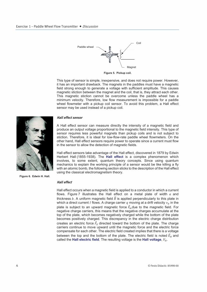
Hall effect occurs when a magnetic field is applied to a conductor in which a current flows. Figure 7 illustrates the Hall effect on a metal plate of width and
thickness . A uniform magnetic field is applied perpendicularly to this plate in which a direct current flows. A charge carrier moving at a drift velocity in the
plate is subject to an upward magnetic force due to the magnetic field. For negative charge carriers, this means that the negative charges accumulate at the top of the plate, which becomes negatively charged while the bottom of the plate becomes positively charged. This discrepancy in the electric charge distribution
creates an electric force directed toward the bottom of the plate. The charge carriers continue to move upward until the magnetic force and the electric force compensate for each other. The electric field created implies that there is a voltage
between the top and the bottom of the plate. The electric field is noted and called the Hall electric field. The resulting voltage is the Hall voltage, .
Figure 6. Edwin H. Hall.
Paddle wheel
Magnet
Coil

Exercise 1 – Paddle Wheel Flow Transmitter Discussion
© Festo Didactic 85998-00 5
Figure 7. Hall effect on a rectangular conductive plate.
The electromagnetic description of the Hall effect
The negative charge carrier shown in Figure 7 is subject to an upward magnetic force:
where is the magnetic force
is the charge of the charge carrier, =-1.602x10⁻¹⁹ C for an electron
is the drift velocity of the charge carrier is the intensity of the uniform magnetic field
is a unitary vector on the z axis The charge carrier is also subject to a downward electric force due to the electric field created by the distribution of the charges on the plate:
where is the electric force
is the intensity of the electric field
The net force on the charge carrier is:
b
a
The top is negatively charged
The bottomis positively
charged

Exercise 1 – Paddle Wheel Flow Transmitter Discussion
6 © Festo Didactic 85998-00
The net force on the charge carrier is null when:
This occurs when:
Thus the Hall voltage is:
Since the current flowing in the plate is:
The drift velocity is:
The Hall voltage can be rewritten as:
where is the Hall coefficient, which is a characteristic of the material the plate is made of.
With the Hall coefficient, the thickness of the plate, the current flowing in the plate, and the measured Hall voltage, it is possible to compute the intensity of the magnetic field.
K factor
Whatever the type of sensor used to detect the paddles, its output is only a series of pulses. The number of pulses produced for a given flow rate depends on the construction of the sensor and of the size of the pipe. Paddle wheel flowmeter manufacturers publish the information required to calculate a factor that allows converting the sensor pulse rate into a flow rate. This factor is called the K factor. It represents the number of pulses produced by the sensor per unit of volume of liquid flowing in the flowmeter.
Industrial applications
Due to their simplicity and low initial cost, paddle wheel flowmeters are widely used in the industry. They are ideal for water or chemical dispensing systems. They are also used for domestic water measurement and for most applications that do not justify paying additional money to increase the precision of the flow rate reading.

Exercise 1 – Paddle Wheel Flow Transmitter Discussion
© Festo Didactic 85998-00 7
Advantages and limitations
The main advantages of paddle wheel flowmeters are:
Simple working principle
Low cost
High repeatability
Easy installation
Paddle wheel flowmeters also have limitations and disadvantages. The most notable are listed below:
Require a fully turbulent flow for accurate measurement
Not suitable for two-phase flow measurement
Subject to wear
Poor linearity at low flow rates
Not recommended for high viscosity or dirty liquids
Require maintenance and cleaning
Description of the supplied paddle wheel flow transmitter
The paddle wheel flow transmitter (Model 46925) is shown below. It consists of a sensor (Figure 8) and a transmitter (Figure 9). Both devices are installed on brackets for mounting on the process workstation. Table 1 and Table 2 describe the main components identified in Figure 8 and Figure 9.
Figure 8. Paddle wheel flowmeter (part of Model 46925).

Exercise 1 – Paddle Wheel Flow Transmitter Discussion
8 © Festo Didactic 85998-00
Table 1. Components of the flowmeter.
Component Description
Inlet Fluid must enter the flowmeter through this port.
Bracket Used to install the flowmeter on the process workstation.
Sensor The sensor assembly containing the paddle wheel and the Hall effect sensor.
Outlet Fluid must exit the flowmeter through this port.
Connection cable A 7.6-meter (25-foot) long cable connects the sensor to the transmitter.
Figure 9. Transmitter of the paddle wheel flowmeter (part of Model 46925).
Table 2. Components of the transmitter.
Component Description
24 V dc input Power input for the flowmeter. Used to energize the paddle wheel flowmeter with a 24 V dc signal.
Analog output Sends a 4-20 mA signal proportional to the measured flow rate.
Fault panel Contains two switches used to simulate faults with the apparatus.
Bracket Used to install the transmitter on the process workstation.
Transmitter/display
The transmitter is connected to the sensor via the connection cable. It displays the measured flow rate and other information related to the operation of the flowmeter. Control keys allow configuring the transmitter.

Exercise 1 – Paddle Wheel Flow Transmitter Discussion
© Festo Didactic 85998-00 9
The display can be used to configure several parameters and to read the flow rate directly. The function of each button is described below:
Toggles between the RATE and TOTAL display modes. If pressed for at least 1.25 seconds, it gives access to the programming mode. Hold the ENTER key to save the changes made in the programming mode.
Allows selecting the digit to modify.
Allows selecting the value of a digit.
Summary of technical specifications
Some technical specifications are summarized in this section. For details, please refer to the documentation provided with the system.
Device name DigiFlo Digital Paddlewheel Meter
Measured variables Flow rate, total volume
Power supply 24 V dc
Output signal 4-20 mA
Sensor Hall effect
Pipe diameter 1.27 cm (0.5 in)
Range for full scale value 1 L/min to 1000 L/min (0.4 gal/min to 300 gal/min)
Full scale accuracy ±1%
Maximum fluid temperature 93°C (200°F)
Ambient temperature -10°C to 43°C (-14°F to 110°F)
Commissioning the paddle wheel flow transmitter
The paddle wheel flow transmitter is pre-configured for flow rate measurement in liters per minute. The flow rate units, as well as other parameters, can be changed from the programming mode of the transmitter. To access the programming mode, press the ENTER button for at least 1.25 seconds. When in the programming mode, use the ENTER button to browse through the parameters. In this mode, three parameters are available for the RATE mode (i.e., flow rate measurement), three parameters for the TOTAL mode (i.e., the volume of fluid that has been through the flowmeter since the last reset), and two parameters for the 4-20 mA output (MA). Table 3 shows the structure of the programming menu of the paddle wheel flow transmitter.

Exercise 1 – Paddle Wheel Flow Transmitter Discussion
10 © Festo Didactic 85998-00
Table 3. Programming menu structure of the paddle wheel flow transmitter.
Parameter1 Description Modification key(s)
RATE 1 Scale factor for flow rate measurement. or
RATE 2 Number of decimals displayed for flow rate measurement.
RATE 3 Battery save mode (on/off).
TOTAL 1 Scale factor (K factor) for total volume measurement. or
TOTAL 2 Number of decimals displayed for total volume measurement.
TOTAL 3 Allows clearing the total volume (on/off).
MA 1 The flow rate value at which the transmitter produces a 4 mA signal. or
MA 2 The flow rate value at which the transmitter produces a 20 mA signal. or
How to calculate the scale factor from the K factor
As mentioned above, the sensor emits a series of pulses; it emits one pulse each time a paddle passes by. The transmitter counts the pulses and computes the flow rate by multiplying the number of pulses by a conversion factor (the scale factor) that takes into account the units and the inner pipe diameter.
The K factor mentioned before is expressed in pulses per unit of volume. The K factor for the paddle wheel flowmeter is: 2631.58 pulse/gal. However, the K factor cannot be used directly as the scale factor for flow rate measurement. The section below describes how to calculate the scale factor from the K factor.
Flow rate scale factor calculation
Flow rates are measured in units of volume per unit of time. A correction factor must be applied to the manufacturer’s K factor in order to obtain the flow rate reading in the desired units of volume and time. The corrected K factor is called the scale factor. It can be entered as a parameter in the programming mode of the paddle wheel flow transmitter. Below are the steps to obtain a scale factor that suits your needs.
1 For flow rate measurement parameters, the transmitter displays RATE at the bottom of the screen, while for total volume measurement it displays TOTAL at the bottom of the screen.

Exercise 1 – Paddle Wheel Flow Transmitter Discussion
© Festo Didactic 85998-00 11
A. Determine the number of decimal places
The flowmeter always displays five digit flow rates, but it is limited to a maximum of four decimal places. The decimal rate factor ( ) allows the user to set the number of decimal places after the point. Table 4 lists the possible decimal rate factors.
Table 4. Number of decimal places.
Position of the decimal point
XXXXX 1
XXXX.X 10
XXX.XX 100
XX.XXX 1000
X.XXXX 10000
B. Determine the time factor
The flowmeter can display the flow rate using various time units. The default time unit is seconds, to obtain a flow rate using minutes, hours, or
days as time unit, use one of the time factors ( ) listed in Table 5.
Table 5. Time factor.
Time unit
seconds 1
minutes 60
hours 3600
days 86400
C. Correct the K factor as a function of the volume units
The manufacturer’s K factor uses gallons as volume units. If you want to use gallons in your flow rate measurement units, you can keep the manufacturer’s K factor as it is. To use other units, you must divide the K factor by one of the unit conversion factors shown in Table 6 to obtain a new K factor. You are not limited to the conversion factors listed in this table, you can use any unit conversion factors, as long as it converts gallons to the volume unit you want to use.

Exercise 1 – Paddle Wheel Flow Transmitter Discussion
12 © Festo Didactic 85998-00
Table 6. Volume unit conversion factors.
Volume unit Divide the K
factor by
Ounces 128
Liters 3.785
Cubic meters 0.003785
D. Calculate the flow rate scale factor
Once you have the decimal rate factor ( ), the time factor ( ), and the
new K factor, you can use them to calculate the flow rate scale factor ( ) using Equation (1):
(1)
E. Use the flow rate scale factor as a parameter
Once you have your flow rate scale factor, you can enter it as the RATE 1 parameter in the programming menu of the transmitter. To do so, press the ENTER button for at least 1.25 seconds and use the up and right arrows to enter the scale factor as the RATE 1 parameter.
Total volume scale factor calculation
The paddle wheel flowmeter can display the total volume of fluid that flowed through the flowmeter since the last reset. The total volume is measured in units of volume. The units of volume used can be the same as the units used for flow measurement, but different units can also be used. Below are the steps to obtain
a total volume scale factor ( ) used to display the total volume of liquid measured by the flowmeter.
A. Determine the number of decimal places
Use Table 4 to determine the decimal rate factor ( ) for the total volume measurement.
B. Correct the K factor as a function of the volume units
Use Table 6 to obtain a new K factor for the total volume measurement. This K factor can be different from the K factor used to calculate the flow rate scale factor.

Exercise 1 – Paddle Wheel Flow Transmitter Discussion
© Festo Didactic 85998-00 13
C. Calculate the total volume scale factor
Once you have the decimal rate factor ( ) and the new K factor, you can use them to calculate the total volume scale factor ( ) using Equation (2):
(2)
D. Use the total volume scale factor as a parameter
Once you have your total volume scale factor, you can enter it as the TOTAL 1 parameter in the programming menu of the transmitter. To do so, press the ENTER button for at least 1.25 seconds, use the ENTER button to select the TOTAL 1 parameter, and use the up and right arrows to enter the scale factor as the TOTAL 1 parameter.
Default parameters of the paddle wheel flow transmitter
The paddle wheel flow transmitter, Model 85925, is pre-configured for flow measurement in liters per minute. Table 7 gives the default setting for both measurements using liters and gallons.
Table 7. Default setting.
Volume unit Liters (L) Gallons (gal)
Flow unit L/min gal/min
Flow rate scale factor 8.630 2.280
Total volume scale factor 0.144 0.038
Number of decimals 2 2
4 mA output at 2 L/min 0.5 gal/min
20 mA output at 20 L/min 5 gal/min

Exercise 1 – Paddle Wheel Flow Transmitter Procedure Outline
14 © Festo Didactic 85998-00
The Procedure is divided into the following sections:
Setup and connections
Using the paddle wheel flow transmitter
Setup and connections
1. Connect the equipment according to the piping and instrumentation diagram (P&ID) shown in Figure 10 and use Figure 11 to position the equipment correctly on the frame of the training system. To set up your system for this exercise, start with the basic setup presented in the Familiarization with the Instrumentation and Process Control Training System manual and add the equipment listed in Table 8.
Table 8. Material to add to the basic setup for this exercise.
Name Model Identification
Paddle wheel flowmeter 46925 FIT 1
Electrical unit 46970
Pneumatic unit 46971
Accessories 46993
Figure 10. P&ID.
PROCEDURE OUTLINE
PROCEDURE

Exercise 1 – Paddle Wheel Flow Transmitter Procedure
© Festo Didactic 85998-00 15
Figure 11. Setup.
2. Connect the control valve to the pneumatic unit. Details about the installation and operation of the control valve are available in the Familiarization with the Instrumentation and Process Control Training System manual.
3. Connect the pneumatic unit to a dry-air source with an output pressure of at least 700 kPa (100 psi).
4. Wire the emergency push-button so that you can cut power in case of emergency. The Familiarization with the Instrumentation and Process Control Training System manual covers the security issues related to the use of electricity with the system as well as the wiring of the emergency push-button.
5. Do not power up the instrumentation workstation yet. Do not turn the electrical panel on before your instructor has validated your setup—that is not before step 9.

Exercise 1 – Paddle Wheel Flow Transmitter Procedure
16 © Festo Didactic 85998-00
6. Connect the transmitter to a 24 V dc power outlet on the electrical unit. Use one of the direct outputs to keep the transmitter from shutting off in case the emergency push-button or the OFF button (S2) is used.
7. Before proceeding further, complete the following checklist to make sure you have set up the system properly. The points on this checklist are crucial elements for the proper completion of this exercise. This checklist is not exhaustive, so be sure to follow the instructions in the Familiarization with the Instrumentation and Process Control Training System manual as well.
f
The ball valves are in the positions shown in the P&ID.
The three-way valve at the suction of the pump (HV1) is set so that the
flow is directed toward the pump inlet.
The control valve is fully open.
The pneumatic connections are correct.
8. Ask your instructor to check and approve your setup.
9. Make sure it is safe to energize the system for you and for the team working on the other side of the system, if any. When ready, turn on the main power. Do not press the S1 button yet.
Using the paddle wheel flow transmitter
10. On the transmitter, press the ENTER button for at least 1.25 seconds to access the programming mode.
11. Use the ENTER button to browse through the programming parameters. Make sure the transmitter is configured with the default settings of Table 7. If not, configure your transmitter with the default setting for flow measurement in either L/min or gal/min.
12. On the electrical unit, press the S1 button to power all the devices not already active on the station (i.e., the drive, the pneumatic devices, etc.).
13. Test your system for leaks. Use the drive to make the pump run at low speed to produce a small flow rate. Gradually increase the flow rate, up to 50% of the maximum flow rate that the pumping unit can deliver (i.e., set the drive speed to 30 Hz). Repair any leaks.
14. Start the pump and set the flow rate to 75% of the maximum flow rate that the pumping unit can deliver (i.e., set the drive speed to 45 Hz).

Exercise 1 – Paddle Wheel Flow Transmitter Procedure
© Festo Didactic 85998-00 17
15. Use the ball valve HV2 to adjust the flow rate so that the rotameter reading is 4 L/min (1 gal/min).
16. Connect a multimeter to the 4-20 mA output.
17. Record both the flow rate reading and the value of the 4-20 mA signal of the transmitter in Table 9.
Table 9. Paddle wheel flow transmitter flow rate reading.
Flow rate (Rotameter)
L/min (gal/min)
Flow rate (Paddle Wheel)L/min (gal/min)
4-20 mA signal (Paddle Wheel)
mA
4 (1)
18. Use the ball valve HV2 to increase the flow rate (as read on the rotameter) by steps of 2 L/min (or 0.5 gal/min) until you reach 18 L/min (4.5 gal/min). For each flow rate, record the flow rate reading and the value of the 4-20 mA signal of the paddle wheel flow transmitter in Table 9.
19. Compare the flow rate reading of the paddle wheel flow transmitter to the flow rate reading of the rotameter.
20. Stop the drive.
21. Configure the transmitter so that it produces an output signal of 20 mA for a flow rate of 2 L/min (0.5 gal/min) and an output signal of 4 mA for a flow rate of 20 L/min (5 gal/min).
22. Start the pump again at 75% of the maximum flow rate that the pumping unit can deliver.
23. Use the ball valve HV2 to adjust the flow rate so that the rotameter reading is 4 L/min (1 gal/min).

Exercise 1 – Paddle Wheel Flow Transmitter Procedure
18 © Festo Didactic 85998-00
24. Record both the flow rate reading and the value of the 4-20 mA signal of the transmitter in Table 10.
Table 10. Paddle wheel flow transmitter flow rate reading.
Flow rate (Rotameter)
L/min (gal/min)
Flow rate (Paddle Wheel)L/min (gal/min)
4-20 mA signal (Paddle Wheel)
mA
4 (1)
25. Use the ball valve HV2 to increase the flow rate (as read on the rotameter) by steps of 2 L/min (or 0.5 gal/min) until you reach 18 L/min (4.5 gal/min). For each flow rate, record the flow rate reading and the value 4-20 mA signal of the paddle wheel flow transmitter in Table 10.
26. Compare the flow rate reading of the paddle wheel flow transmitter to the flow rate reading of the rotameter.
27. Stop the drive.
28. Use the instructions from the How to calculate the scale factor from the K factor section to configure the transmitter so that the flow rate units are in cubic meters per hour. Also, set the output parameters so that the output signal is 4 mA for a flow rate of 0.12 m3/h and 20 mA for a flow rate of 1.2 m3/h.
29. What is the scale factor for a flow rate reading in m3/h?
30. Start the pump again at 75% of the maximum flow rate that the pumping unit can deliver.
31. Use the ball valve HV2 to adjust the flow rate so that the rotameter reading is 4 L/min (1 gal/min).

Exercise 1 – Paddle Wheel Flow Transmitter Conclusion
© Festo Didactic 85998-00 19
32. Record both the flow rate reading and the value of the 4-20 mA signal of the transmitter in Table 11.
Table 11. Paddle wheel flow transmitter flow rate reading.
Flow rate (Rotameter)
L/min (gal/min)
Flow rate (Paddle Wheel)
m3/h
4-20 mA signal (Paddle Wheel)
mA
4 (1)
33. Use the ball valve HV2 to increase the flow rate (as read on the rotameter) by steps of 2 L/min (or 0.5 gal/min) until you reach 18 L/min (4.5 gal/min). For each flow rate, record the flow rate reading and the value 4-20 mA signal of the paddle wheel flow transmitter in Table 11.
34. Compare the flow rate reading of Table 11 with the flow rate reading of Table 9.
35. Stop the pump and turn off the power to the system.
You should now be able to configure the paddle wheel flow transmitter, Model 46925, to measure a flow rate. You should also be able to calculate a scale factor and configure the transmitter to display the flow rate in the desired units.
1. Describe how a paddle wheel flowmeter works?
CONCLUSION
REVIEW QUESTIONS

Exercise 1 – Paddle Wheel Flow Transmitter Review Questions
20 © Festo Didactic 85998-00
2. What type of flow profile allows getting the best accuracy from the paddle wheel flowmeter? Why?
3. What is the Hall effect?
4. What is the K factor of a paddle wheel flowmeter?
5. Name two advantages and two limitations of the paddle wheel flowmeter.