Embed Size (px)
Citation preview
USER MANUAL
GFK-3050E
May 2021
PACSystemsTM RX3i Sequence of Events USER MANUAL
PACSystems RX3i Sequence of Events User Manual Contents GFK-3050E May 2021
Contents i
Contents
Section 1 Introduction ...................................................... 1
1.1 Key Features ................................................................................................. 2
1.1.1 High System Availability...................................................................... 2
1.1.2 Time-stamps to ±1 ms Accuracy ......................................................... 2
1.1.3 Components ....................................................................................... 3
1.2 Glossary of Terms.......................................................................................... 6
1.3 Revisions in this Manual ................................................................................ 6
1.4 PACSystems Documentation ........................................................................ 7
Section 2 RX3i Hardware Configuration ............................ 8
2.1 CPU Configuration ........................................................................................ 8
2.1.1 Redundant Systems .......................................................................... 11
2.2 SoE Node Configuration .............................................................................. 12
2.2.1 Physical Constraints for Devices in an SoE Node ................................ 12
2.2.2 I/O Mapping for Devices in an SoE Node ............................................ 13
2.3 PNS Selection .............................................................................................. 14
2.4 PNS Configuration ...................................................................................... 15
2.4.1 Module Parameters .......................................................................... 15
2.5 High-Speed Counter (HSC) Configuration ................................................... 16
2.6 MDL660 Configuration ................................................................................ 16
2.7 MDL655 Configuration ................................................................................ 18
Section 3 IRIG-B Set-up & Interface ................................. 19
3.1 Connecting the IRIG-B to HSC Input ............................................................ 20
3.2 Synchronization of the CPU System Clock ................................................... 21
Section 4 SoE/IRIG-B User Memory-Map .......................... 22
4.1 Memory-Map Definitions ............................................................................ 24
4.2 Configuration/Set-up Status ....................................................................... 26
4.3 Configuration Errors .................................................................................... 27
4.3.1 Invalid Device Number (Error Code 662) ........................................... 27
4.3.2 Collector Access Denied (Error Code 663) ......................................... 28
Section 5 Operation ........................................................ 29
5.1 Functions of the C Program Blocks .............................................................. 30

PACSystems RX3i Sequence of Events User Manual Contents GFK-3050E May 2021
Contents ii
5.1.1 Set up the Input and Output Parameters for the C Program Block ..... 31
5.1.2 Install Ladder Logic in Support of C-Block .......................................... 32
5.2 Functions of the Input Modules (MDL660/MDL655) .................................... 33
5.3 Functions of the High-Speed Counter (HSC) ................................................ 33
5.4 Functions of the Advanced PROFINET Scanner (PNS101) ............................. 34
5.4.1 Input Status Bits ................................................................................ 35
5.5 Functions of the PROFINET Controller (PNC) ................................................ 36
5.6 Functions of the CPU ................................................................................... 36
5.7 Functions of a Historian/SoE Collector ......................................................... 36
5.8 Performance Considerations ....................................................................... 37
Section 6 Diagnostics ..................................................... 39
6.1 Configuring the SoE Diagnostic Block .......................................................... 39
6.2 Monitoring SoE Diagnostics ........................................................................ 41
6.2.1 SoE Diagnostic Definitions ................................................................ 42
General Contact Information ................................................................................. 63
Technical Support ................................................................................................. 63
PACSystems RX3i Sequence of Events User Manual Section 1 GFK-3050E May 2021
Introduction 1
Section 1 Introduction
Capturing a sequence of events is important in a variety of automation applications. The
goal is to configure the target system to continuously capture any change in the state of
selected I/O points throughout the application, store the resultant records into a managed
depository, then be in a position to analyze the sequence of events that led up to a trigger
situation, such as the inadvertent opening of a valve, or some other unintended operation
of the overall system.
The key to capturing intelligible data is synchronizing all devices throughout the system to
a common time-base and using a time-base with a degree of resolution that is meaningful
for the application. The time-base is used to time-stamp each event recorded. By analyzing
the captured sequence of events, the automation designer or system operator can
reconstruct the activities that led up to the trigger event, and thereby correct or adjust the
operation to achieve a more desirable outcome.
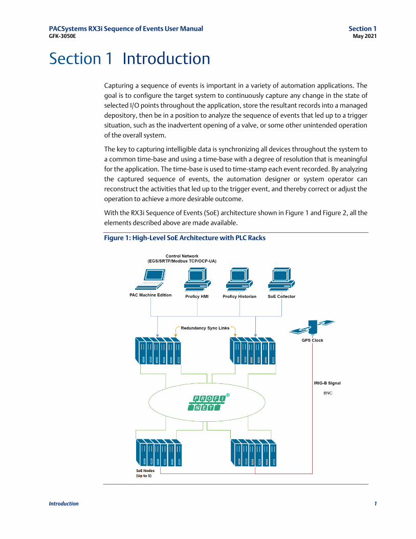
With the RX3i Sequence of Events (SoE) architecture shown in Figure 1 and Figure 2, all the
elements described above are made available.
Figure 1: High-Level SoE Architecture with PLC Racks

PACSystems RX3i Sequence of Events User Manual Section 1 GFK-3050E May 2021
Introduction 2
Figure 2: High-Level SoE Architecture with CPE400/CPL410s
1.1 Key Features
1.1.1 High System Availability
The RX3i solution relies on a system configuration that provides high reliability and is
compatible with both redundant and simplex applications. The I/O is connected via the
industry-standard PROFINET. The CPUs are interconnected via high-speed links that
synchronize the redundant CPUs, if redundancy is used. The computer used to collect the
sequence of events records is attached via a high-speed, high-availability Ethernet link.
1.1.2 Time-stamps to ±1 ms Accuracy
The IRIG-B time reference signal, used to establish a system-wide time-base, is directly
connected to High-Speed Counter modules distributed throughout the network via a
dedicated signal network.

PACSystems RX3i Sequence of Events User Manual Section 1 GFK-3050E May 2021
Introduction 3
This solution provides time synchronization of I/O events accurate to ±1 ms1 using
unmodulated IRIG-B formatted signals.
1.1.3 Components
The CPUs which support the SoE implementation are IC695CPE330, IC695CPE400, and
IC695CPL410.
To implement SoE, the compatible controller project folder (in PAC Machine Edition) must
contain a pair of dedicated C program blocks designed to configure and collect SoE records
and provide diagnostic features.
The user defines which I/O points are to be monitored as part of the SoE data collection
using the CPU registers used to interface with the C Block, and by configuring those points
on the input module.
Each CPU is configured to use its embedded PROFINET Controller (PNC). Rack-mounted
PROFINET Controllers may not be used to collect SoE records.
The CPE330 may be configured for simplex operation or PROFINET redundancy. If PROFINET
redundancy is configured, the high-speed redundancy links are provided by a pair of RMX
modules (IC695RMX128 or IC695RMX228), two installed in each CPU rack of the redundant
pair. The CPE400/CPL410 may be configured for simplex or PROFINET redundancy without
additional hardware: the two ports on the LAN3 provide high-speed data synchronization
between the two CPUs.
Each PNC may control up to five2 PROFINET nodes collecting SoE data. These are designated
SoE Nodes in this document. Each SoE node is equipped with an RX3i Advanced PROFINET
Scanner Module (PNS101). The PNS101 contains features required in the SoE Application.
The PNC is networked to its PNS modules over PROFINET, which may itself be configured for
Media Redundancy (MRP mode). The PNC may control additional PROFINET IO Devices (not
collecting SoE Data) based on its documented capabilities.
Up to four Discrete Input modules may be installed in any given PNS node. An SoE event is
defined as a transition (low-to-high or high-to-low) on any of these inputs, provided they
have been configured as an SoE channel to be monitored.
Each PNS can buffer up to 4,000 events in its event queue at a maximum rate of 400 events
per second.
The I/O events are time-stamped by the PNS as they are scanned.
The PNS time-stamps are synchronized to the IRIG-B time-base via a High-Speed Counter
(HSC) located within the same rack, thus all time-stamps are referenced to a common clock.
The IRIG-B/HSC interface is described in Section 1
1 Calculated with 90% confidence interval.
2 Starting with PACSystems RX3i Controller firmware release 10.15, each Embedded PNC may control up to 5 SoE nodes. Earlier firmware
releases that support SoE, may control up to 4 SoE nodes.
PACSystems RX3i Sequence of Events User Manual Section 1 GFK-3050E May 2021
Introduction 4
Each SoE event is compiled into an SoE Record by the supervising PNS module. The SoE
Record pinpoints the location of the input channel, the nature of the transition, and a time-
stamp.
The SoE records from each of the PNS modules are passed to its networked CPU Embedded
PNC and are then consolidated by the host CPU. The consolidated record set is placed in CPU
reference memory as configured by the user (refer to Section 4).
The Historian/SoE Collector (Cimplicity Historian/SQL database) can read the CPU’s SoE
Records Buffer using a variety of techniques: SRTP, EGD, etc. The CPU indicates how many
records are present in that buffer. The Historian/SoE Collector, after reading these records,
indicates to the CPU that they have been read. For details, refer to Section 5.7.
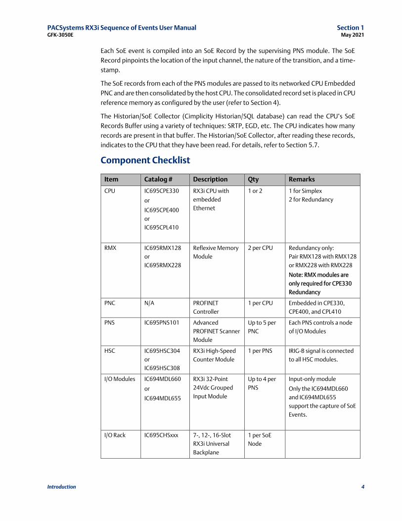
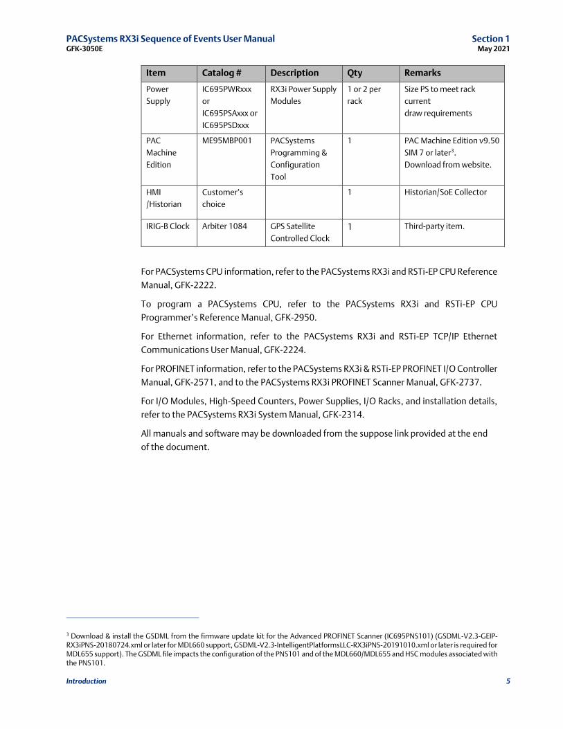
Component Checklist
Item Catalog # Description Qty Remarks
CPU IC695CPE330
or
IC695CPE400
or
IC695CPL410
RX3i CPU with
embedded
Ethernet
1 or 2 1 for Simplex
2 for Redundancy
RMX IC695RMX128
or
IC695RMX228
Reflexive Memory
Module
2 per CPU Redundancy only:
Pair RMX128 with RMX128
or RMX228 with RMX228
Note: RMX modules are
only required for CPE330
Redundancy
PNC N/A PROFINET
Controller
1 per CPU Embedded in CPE330,
CPE400, and CPL410
PNS IC695PNS101 Advanced
PROFINET Scanner
Module
Up to 5 per
PNC
Each PNS controls a node
of I/O Modules
HSC IC695HSC304
or
IC695HSC308
RX3i High-Speed
Counter Module
1 per PNS IRIG-B signal is connected
to all HSC modules.
I/O Modules IC694MDL660
or
IC694MDL655
RX3i 32-Point
24Vdc Grouped
Input Module
Up to 4 per
PNS
Input-only module
Only the IC694MDL660
and IC694MDL655
support the capture of SoE
Events.
I/O Rack IC695CHSxxx 7-, 12-, 16-Slot
RX3i Universal
Backplane
1 per SoE
Node
PACSystems RX3i Sequence of Events User Manual Section 1 GFK-3050E May 2021
Introduction 5
Item Catalog # Description Qty Remarks
Power
Supply
IC695PWRxxx
or
IC695PSAxxx or
IC695PSDxxx
RX3i Power Supply
Modules
1 or 2 per
rack
Size PS to meet rack
current
draw requirements
PAC
Machine
Edition
ME95MBP001 PACSystems
Programming &
Configuration
Tool
1 PAC Machine Edition v9.50
SIM 7 or later3.
Download from website.
HMI
/Historian
Customer’s
choice
1 Historian/SoE Collector
IRIG-B Clock Arbiter 1084 GPS Satellite
Controlled Clock
1 Third-party item.
For PACSystems CPU information, refer to the PACSystems RX3i and RSTi-EP CPU Reference
Manual, GFK-2222.
To program a PACSystems CPU, refer to the PACSystems RX3i and RSTi-EP CPU
Programmer’s Reference Manual, GFK-2950.
For Ethernet information, refer to the PACSystems RX3i and RSTi-EP TCP/IP Ethernet
Communications User Manual, GFK-2224.
For PROFINET information, refer to the PACSystems RX3i & RSTi-EP PROFINET I/O Controller
Manual, GFK-2571, and to the PACSystems RX3i PROFINET Scanner Manual, GFK-2737.
For I/O Modules, High-Speed Counters, Power Supplies, I/O Racks, and installation details,
refer to the PACSystems RX3i System Manual, GFK-2314.
All manuals and software may be downloaded from the suppose link provided at the end
of the document.
3 Download & install the GSDML from the firmware update kit for the Advanced PROFINET Scanner (IC695PNS101) (GSDML-V2.3-GEIP-RX3iPNS-20180724.xml or later for MDL660 support, GSDML-V2.3-IntelligentPlatformsLLC-RX3iPNS-20191010.xml or later is required for MDL655 support). The GSDML file impacts the configuration of the PNS101 and of the MDL660/MDL655 and HSC modules associated with the PNS101.
PACSystems RX3i Sequence of Events User Manual Section 1 GFK-3050E May 2021
Introduction 6
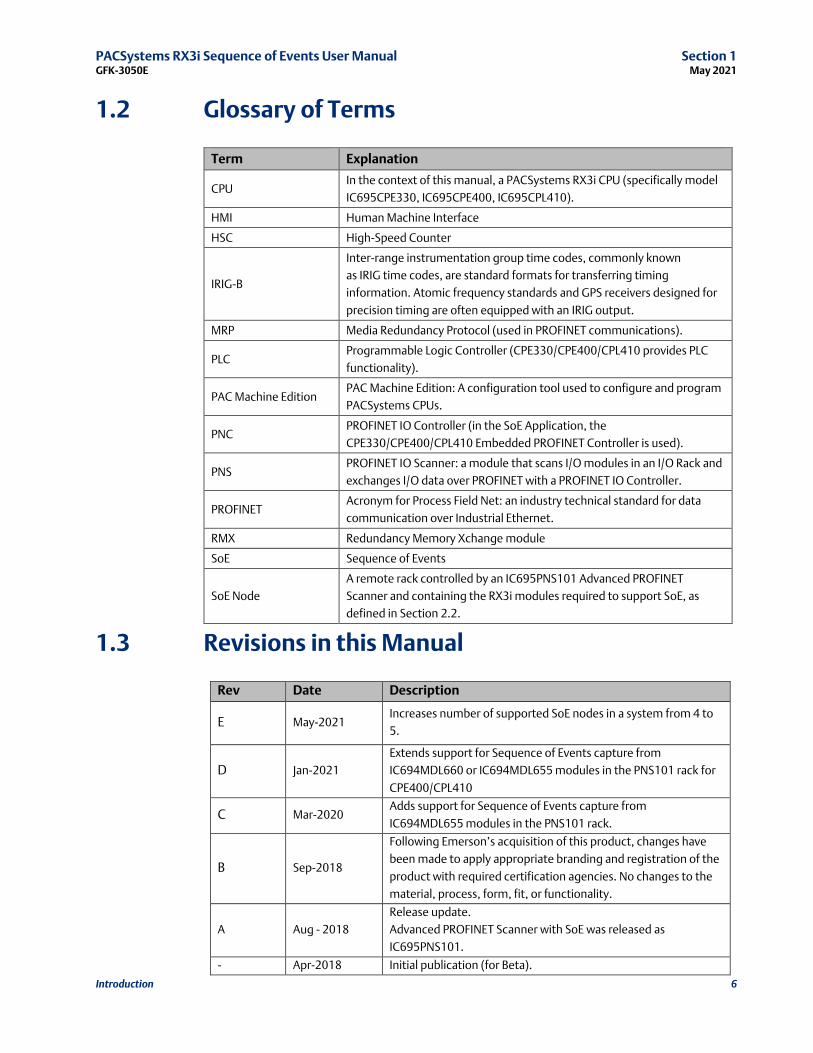
1.2 Glossary of Terms
Term Explanation
CPU In the context of this manual, a PACSystems RX3i CPU (specifically model
IC695CPE330, IC695CPE400, IC695CPL410).
HMI Human Machine Interface
HSC High-Speed Counter
IRIG-B
Inter-range instrumentation group time codes, commonly known
as IRIG time codes, are standard formats for transferring timing
information. Atomic frequency standards and GPS receivers designed for
precision timing are often equipped with an IRIG output.
MRP Media Redundancy Protocol (used in PROFINET communications).
PLC Programmable Logic Controller (CPE330/CPE400/CPL410 provides PLC
functionality).
PAC Machine Edition PAC Machine Edition: A configuration tool used to configure and program
PACSystems CPUs.
PNC PROFINET IO Controller (in the SoE Application, the
CPE330/CPE400/CPL410 Embedded PROFINET Controller is used).
PNS PROFINET IO Scanner: a module that scans I/O modules in an I/O Rack and
exchanges I/O data over PROFINET with a PROFINET IO Controller.
PROFINET Acronym for Process Field Net: an industry technical standard for data
communication over Industrial Ethernet.
RMX Redundancy Memory Xchange module
SoE Sequence of Events
SoE Node
A remote rack controlled by an IC695PNS101 Advanced PROFINET
Scanner and containing the RX3i modules required to support SoE, as
defined in Section 2.2.
1.3 Revisions in this Manual
Rev Date Description
E May-2021 Increases number of supported SoE nodes in a system from 4 to
5.
D Jan-2021
Extends support for Sequence of Events capture from
IC694MDL660 or IC694MDL655 modules in the PNS101 rack for
CPE400/CPL410
C Mar-2020 Adds support for Sequence of Events capture from
IC694MDL655 modules in the PNS101 rack.
B Sep-2018
Following Emerson’s acquisition of this product, changes have
been made to apply appropriate branding and registration of the
product with required certification agencies. No changes to the
material, process, form, fit, or functionality.
A Aug - 2018
Release update.
Advanced PROFINET Scanner with SoE was released as
IC695PNS101.
- Apr-2018 Initial publication (for Beta).

PACSystems RX3i Sequence of Events User Manual Section 1 GFK-3050E May 2021
Introduction 7
1.4 PACSystems Documentation
A complete Sequence of Events application system incorporates a variety of hardware and
software components.
A simple SoE ladder application template, along with C Blocks, and the Diagnostic UDTs
referenced later in this document are available for download at the Emerson support
website. The latest information can be obtained by searching for the PNS101 Landing Page
and following SoE references there.
PACSystems Manuals
PACSystems RX3i and RSTi-EP CPU Reference Manual GFK-2222
PACSystems RX3i and RSTi-EP CPU Programmer’s
Reference Manual GFK-2950
PACSystems RX3i and RSTi-EP TCP/IP Ethernet
Communications User Manual GFK-2224
PACSystems TCP/IP Ethernet Communications Station
Manager User Manual GFK-2225
C Programmer’s Toolkit for PACSystems GFK-2259
PACSystems Memory Xchange Modules User’s Manual GFK-2300
PACSystems Hot Standby CPU Redundancy User Manual GFK-2308
PACSystems Battery and Energy Pack Manual GFK-2741
PAC Machine Edition Logic Developer Getting Started GFK-1918
PACSystems RXi, RX3i and RSTi-EP Controller
Secure Deployment Guide GFK-2830
PACSystems RX3i & RSTi-EP PROFINET I/O Controller Manual GFK-2571
RX3i Manuals
PACSystems RX3i System Manual GFK-2314
PACSystems RX3i Ethernet Network Interface Unit User’s Manual GFK-2439
PACSystems RX3i PROFINET Scanner Manual GFK-2737
PACSystems RX3i Serial Communications Modules User’s Manual GFK-2460
PACSystems RX3i High-Speed Counter Modules User’s Manual GFK-2441
In addition to these manuals, datasheets and product update documents describe
individual modules and product revisions. The most recent PACSystems documentation is
available on the Emerson support website https://www.emerson.com/Industrial-
Automation-Controls/support
PACSystems RX3i Sequence of Events User Manual Section 2 GFK-3050E May 2021
RX3i Hardware Configuration 8
Section 2 RX3i Hardware Configuration
A Sequence of Events configuration is comprised of two parts: the setup of a Hardware
Configuration profile in PAC Machine Edition and SoE/IRIG-B User Memory Map data read by
the SoE Application C Block. This section describes the Hardware Configuration profile in
PAC Machine Edition. For information on the SoE/IRIG-B User Memory Map, see Section 4.
2.1 CPU Configuration
The SoE functionality is supported by the CPE330, CPE400, and CPL410. The following
firmware versions are required to support the SoE C Block.
Controller Firmware Versions Supporting SoE C Block
CPE330 9.60 or later
CPE400/CPL410 10.10
To ensure the CPU firmware version supports the SoE C Block, the CPE330 requires
firmware version 9.60 or later. The CPE400 and CPL410 require firmware versions 10.10 or
later.
The following instructions will illustrate the configuration of an SoE configuration on a
CPE330, but the instructions are identical for the CPE400 or CPL410.
Note: These instructions are specific to simplex configuration. Section 2.1.1 Redundant
Systems, provides instruction on specific hardware configuration changes and
considerations for the setup of a redundant system.
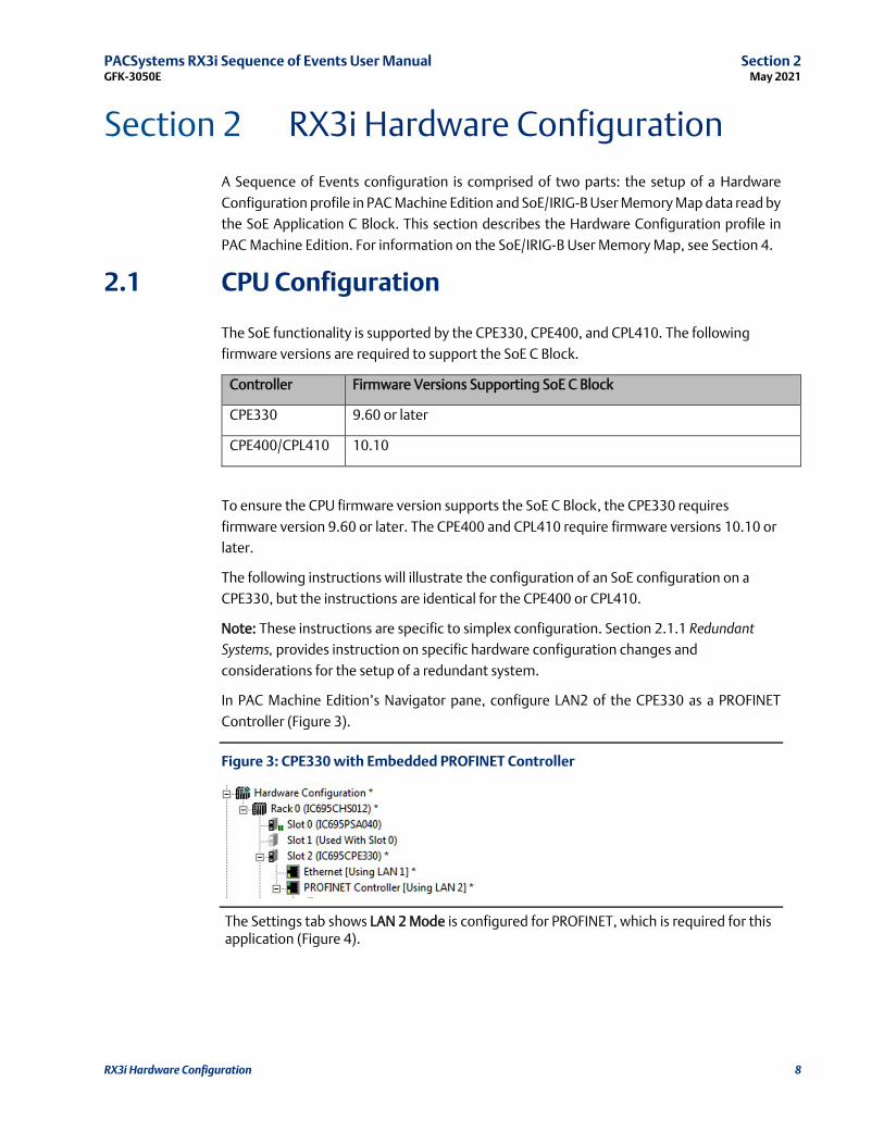
In PAC Machine Edition’s Navigator pane, configure LAN2 of the CPE330 as a PROFINET
Controller (Figure 3).
Figure 3: CPE330 with Embedded PROFINET Controller
The Settings tab shows LAN 2 Mode is configured for PROFINET, which is required for this application (Figure 4).

PACSystems RX3i Sequence of Events User Manual Section 2 GFK-3050E May 2021
RX3i Hardware Configuration 9
Figure 4: CPE330 Settings Showing LAN2 Mode = PROFINET
Once the PROFINET controller has been configured, add nodes to the PROFINET network.
For an SoE operation, an IC695PNS101 is selected as a module to be added. In Figure 3, it is
displayed in PAC Machine Edition as an Advanced PROFINET Scanner. Each PNS101 added
will function as the head-end of the RX3i rack containing all the hardware required to
support SoE. (For further discussions consult Section 2.2, SoE Node Configuration.) Up to
five PNS101 modules may be added in this fashion.
SoE functionality requires locating and reserving two blocks of memory; a 151-word User
Memory Map area that is specified as one of the input parameters to the SoE Application C
Block; and an SoE Records Buffer whose size and location is configured within the User
Memory Map. (The SoE Records Buffer size is defined by the number of records specified in
element 17 of the SoE Memory Map multiplied by 10 words per record for a size of up to
320,000 words.) Each block may be in any of the Word-type Reference memory areas; i.e.
%W, %R, %AI, or %AQ. Reference Memory area sizes are user-configured on the CPU’s
Memory tab and must allocate enough memory for the highest memory reference used.
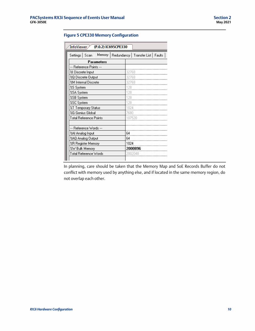
Figure 5 shows a configuration that is utilizing %W memory for both the Memory Map and
SoE Records Buffer.
PACSystems RX3i Sequence of Events User Manual Section 2 GFK-3050E May 2021
RX3i Hardware Configuration 10
Figure 5 CPE330 Memory Configuration
In planning, care should be taken that the Memory Map and SoE Records Buffer do not
conflict with memory used by anything else, and if located in the same memory region, do
not overlap each other.
PACSystems RX3i Sequence of Events User Manual Section 2 GFK-3050E May 2021
RX3i Hardware Configuration 11
2.1.1 Redundant Systems
In a system configured for Hot Standby Redundancy, the active controller must synchronize
its SoE Records Buffer with the backup controller on every sweep. This can significantly
increase sweep time if the external Historian/SoE Collector is not keeping up with the SoE
events being generated; therefore, the CPU Watchdog Timer parameter will need to be
increased.
The Watchdog Timeout should be equal to the normal sweep time plus the worst-case
sweep impact values seen in table. For example, if the sweep is normally 100 ms with no
SoE records buffered internally, then the Watchdog Timeout should be set to at least 220
ms (100 + 120 = 220 ms).
Table 1: Worst-Case Sweep Impact Values
Controller Worst-Case Sweep Impact (ms) Watchdog Timeout (ms)
CPE330 120 100 + 120 = 220
CPE400/CPL410 200 100 + 200 = 300
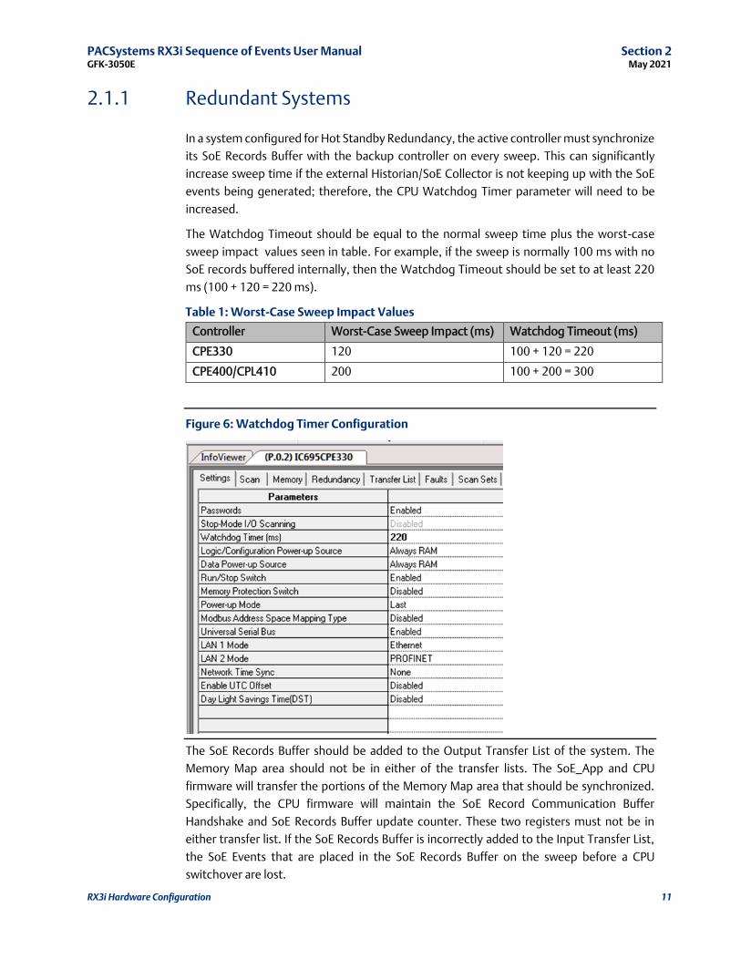
Figure 6: Watchdog Timer Configuration
The SoE Records Buffer should be added to the Output Transfer List of the system. The
Memory Map area should not be in either of the transfer lists. The SoE_App and CPU
firmware will transfer the portions of the Memory Map area that should be synchronized.
Specifically, the CPU firmware will maintain the SoE Record Communication Buffer
Handshake and SoE Records Buffer update counter. These two registers must not be in
either transfer list. If the SoE Records Buffer is incorrectly added to the Input Transfer List,
the SoE Events that are placed in the SoE Records Buffer on the sweep before a CPU
switchover are lost.
PACSystems RX3i Sequence of Events User Manual Section 2 GFK-3050E May 2021
RX3i Hardware Configuration 12
Remote Station Overflow bits are not maintained redundantly. They are set on the active
unit on the first read of records after an overflow has occurred. If it is desired to maintain
these accurately on a redundant system, they should be operator OR’d into a variable from
User Logic and that variable should be placed on the Output Transfer List.
Similarly, the Overflow bit (bit 1) of the SoE Status register is set when new data is received
on the active unit that would overflow the buffer. When SoE data is transferred to the
backup unit, the overflow condition is not sent. When the backup unit transitions to the
active unit, it has all the internal events transferred, and the ½ full and ¾ full bits will be
correctly set based on that internal data, but an overflow bit will not be maintained. If it is
necessary to maintain the overflow condition between redundant CPUs, the SoE Status
register should be placed on the Output Transfer List.
2.2 SoE Node Configuration
2.2.1 Physical Constraints for Devices in an SoE Node
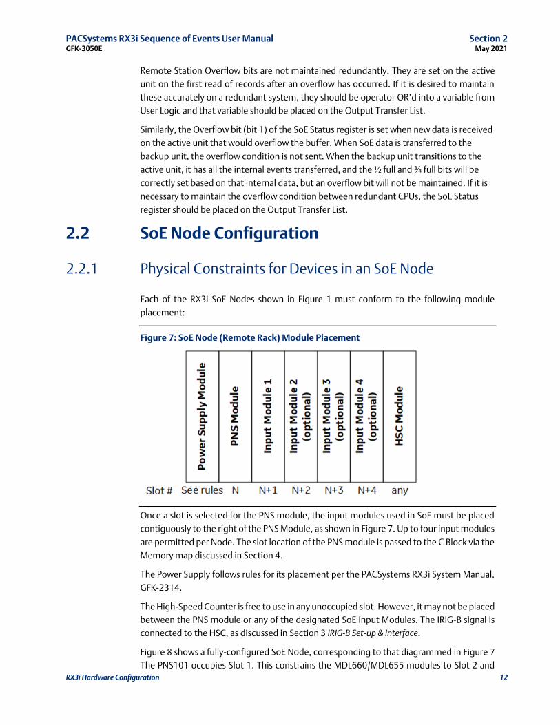
Each of the RX3i SoE Nodes shown in Figure 1 must conform to the following module
placement:
Figure 7: SoE Node (Remote Rack) Module Placement
Once a slot is selected for the PNS module, the input modules used in SoE must be placed
contiguously to the right of the PNS Module, as shown in Figure 7. Up to four input modules
are permitted per Node. The slot location of the PNS module is passed to the C Block via the
Memory map discussed in Section 4.
The Power Supply follows rules for its placement per the PACSystems RX3i System Manual,
GFK-2314.
The High-Speed Counter is free to use in any unoccupied slot. However, it may not be placed
between the PNS module or any of the designated SoE Input Modules. The IRIG-B signal is
connected to the HSC, as discussed in Section 3 IRIG-B Set-up & Interface.
Figure 8 shows a fully-configured SoE Node, corresponding to that diagrammed in Figure 7
The PNS101 occupies Slot 1. This constrains the MDL660/MDL655 modules to Slot 2 and

PACSystems RX3i Sequence of Events User Manual Section 2 GFK-3050E May 2021
RX3i Hardware Configuration 13
higher (contiguously). The Power Supply occupies Slot 0 and the HSC occupies Slot 6. The
whole arrangement fits in a 7-slot RX3i backplane.
Figure 8: Fully-Configured SoE Node (Remote Rack)
For full details on configuring a PROFINET Controller, refer to the PACSystems RX3i & RSTi-
EP PROFINET I/O Controller Manual, GFK-2571.
For full details on configuring a PROFINET Scanner, refer to the PACSystems RX3i PROFINET
Scanner Manual, GFK-2737.
2.2.2 I/O Mapping for Devices in an SoE Node
As shown in Figure 7, the Input Modules and PNS are constrained to a fixed physical
arrangement. Similarly, within each SoE Node, the mapping of those inputs into the host
CPU reference memory is fixed relative to one another, as described in this section. If PAC
Machine Edition has any problems accepting the planned reference assignments, the user
must either change some external reference assignments or alter the planned reference
assignments in PAC Machine Edition.
The base index for each SoE Node is defined in Section 4, SoE/IRIG-B User Memory-Map.
These assignments are passed to the C-Block.
Note: Since multiple PNS modules may be present in the SoE structure, this document is
using PNS(x) to denote the PNS module located in SoE Node x in the Memory Map. Thus
PNS(1) represents the PNS in Node 1, PNS(2) represents the PNS located in SoE Node 2, etc.
Each PNS(x) has a unique range of map elements associated with it, per Section 4.
For PNS(1), the definition is presented in Element (26) and Element (27). Thus,
• if Element (26) is set to 16(dec), the CPU reference memory type is defined as %I;
• if Element (27) = 1001, the starting reference for this SoE Node is %I1001.
PACSystems RX3i Sequence of Events User Manual Section 2 GFK-3050E May 2021
RX3i Hardware Configuration 14
Device Required/
Optional Reference Assigned
Number
of Bits Example
PNS(1) Required Per Element (26) and
Element (27) 32 %I1001 - %I1032
Input Module 1 Required Next contiguous 32 %I1033-%I1064
Input Module 2 Optional Next contiguous, if used 32 %I1065-%I1096
Input Module 3 Optional Next contiguous, if used 32 %I1097-%I1128
Input Module 4 Optional Next contiguous, if used 32 %I1129-%I1160
HSC (IRIG-B) Required None
The PROFINET Scanner Module also consumes 32 bits of output data. Refer to the
PACSystems RX3i PROFINET Scanner Manual, GFK-2737.
2.3 PNS Selection
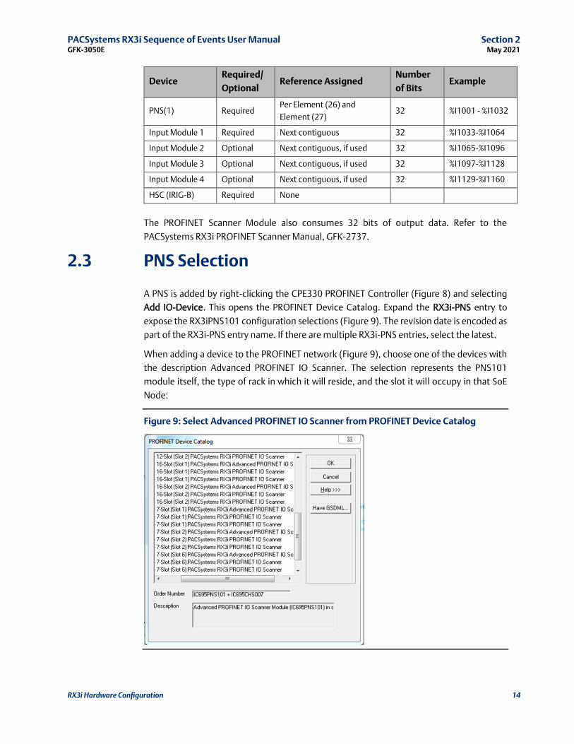
A PNS is added by right-clicking the CPE330 PROFINET Controller (Figure 8) and selecting
Add IO-Device. This opens the PROFINET Device Catalog. Expand the RX3i-PNS entry to
expose the RX3iPNS101 configuration selections (Figure 9). The revision date is encoded as
part of the RX3i-PNS entry name. If there are multiple RX3i-PNS entries, select the latest.
When adding a device to the PROFINET network (Figure 9), choose one of the devices with
the description Advanced PROFINET IO Scanner. The selection represents the PNS101
module itself, the type of rack in which it will reside, and the slot it will occupy in that SoE
Node:
Figure 9: Select Advanced PROFINET IO Scanner from PROFINET Device Catalog
PACSystems RX3i Sequence of Events User Manual Section 2 GFK-3050E May 2021
RX3i Hardware Configuration 15
If the particular version of Advanced PROFINET IO Scanner is not available, or an updated
GSDML file has been made available, click on the Have GSDML button (Figure 9) and browse
to the folder containing the new GSDML file, then import that file to the PROFINET Device
Catalog. Detailed instructions are provided in the PACSystems RX3i & RSTi-EP PROFINET I/O
Controller Manual, GFK-2571.
GSDML files are available for download (as part of the PNS101 firmware update kits) at the
support links located at the end of this document.
2.4 PNS Configuration
The Update Rate of the PNS scan should be set to either the fastest supported for the overall
system (see PROFINET IO controller documentation for the fastest rate supported for the
number of nodes in the system) or considering the rate of SoE Records generated. The CPU
uses the PNS status bits to know if there are any records available to be retrieved. If too many
records occur before the update of the PNS status bits, an overflow can occur within the PNS
internal queue and events will be lost.
2.4.1 Module Parameters
Figure 10 PNS Module Settings Tab
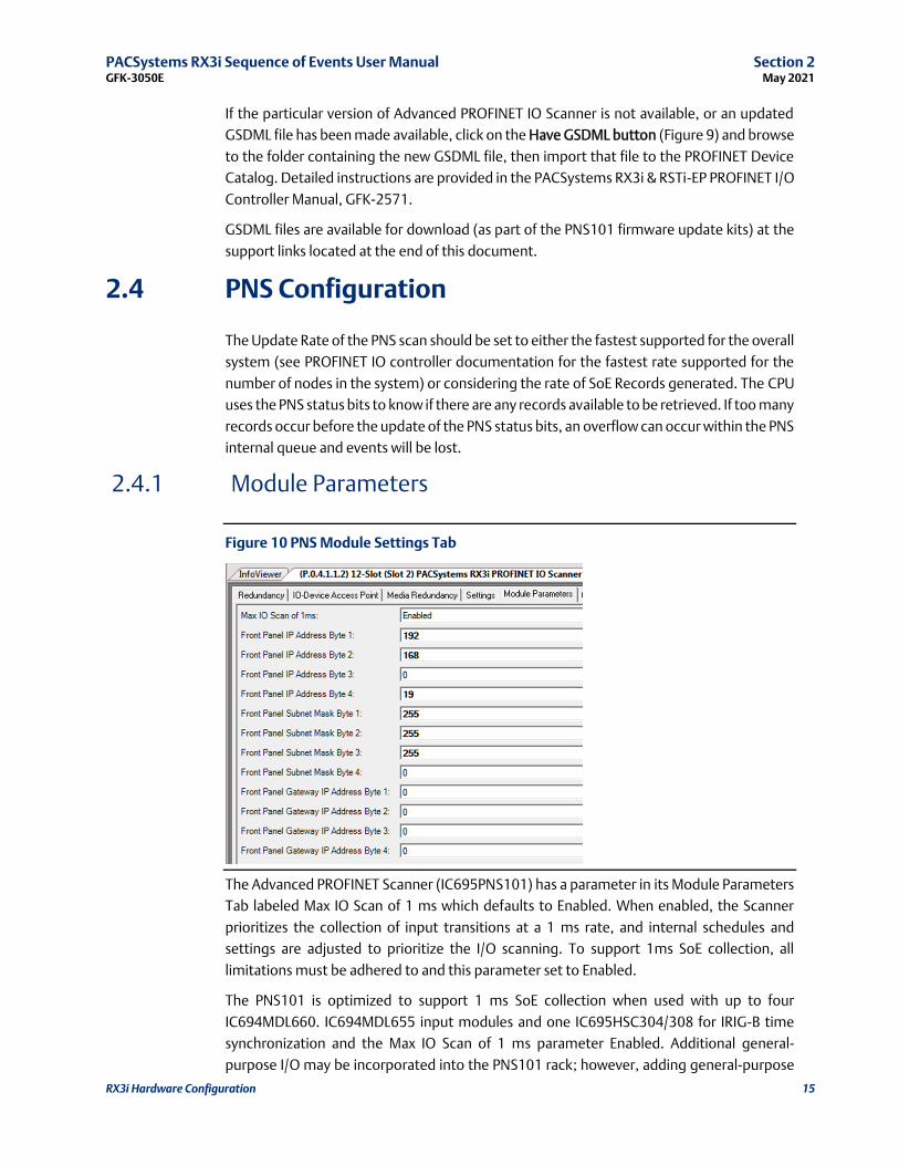
The Advanced PROFINET Scanner (IC695PNS101) has a parameter in its Module Parameters
Tab labeled Max IO Scan of 1 ms which defaults to Enabled. When enabled, the Scanner
prioritizes the collection of input transitions at a 1 ms rate, and internal schedules and
settings are adjusted to prioritize the I/O scanning. To support 1ms SoE collection, all
limitations must be adhered to and this parameter set to Enabled.
The PNS101 is optimized to support 1 ms SoE collection when used with up to four
IC694MDL660. IC694MDL655 input modules and one IC695HSC304/308 for IRIG-B time
synchronization and the Max IO Scan of 1 ms parameter Enabled. Additional general-
purpose I/O may be incorporated into the PNS101 rack; however, adding general-purpose
PACSystems RX3i Sequence of Events User Manual Section 2 GFK-3050E May 2021
RX3i Hardware Configuration 16
I/O increases the PNS101 IO scan time and the PNS101 may not be able to maintain a 1 ms
SoE collection rate. For the best performance, general-purpose I/O should be in a separate
PROFINET Scanner rack and not added to a dedicated PNS101 SoE Node. If general-purpose
I/O modules are present in the PNS101 SoE node, best-effort SoE collection can be used. In
that case, the Max IO Scan of 1 ms parameter should be set to Disabled to allow for I/O scans
potentially longer than 1 ms and correct servicing of the SoE and general purpose of I/O
modules in a given PNS101 SoE node. SoE collection will occur at the I/O scan rate of the
PNS101 which may be longer than 1ms. In this case, events occurring faster than the
PNS101 I/O scan rate may be missed.
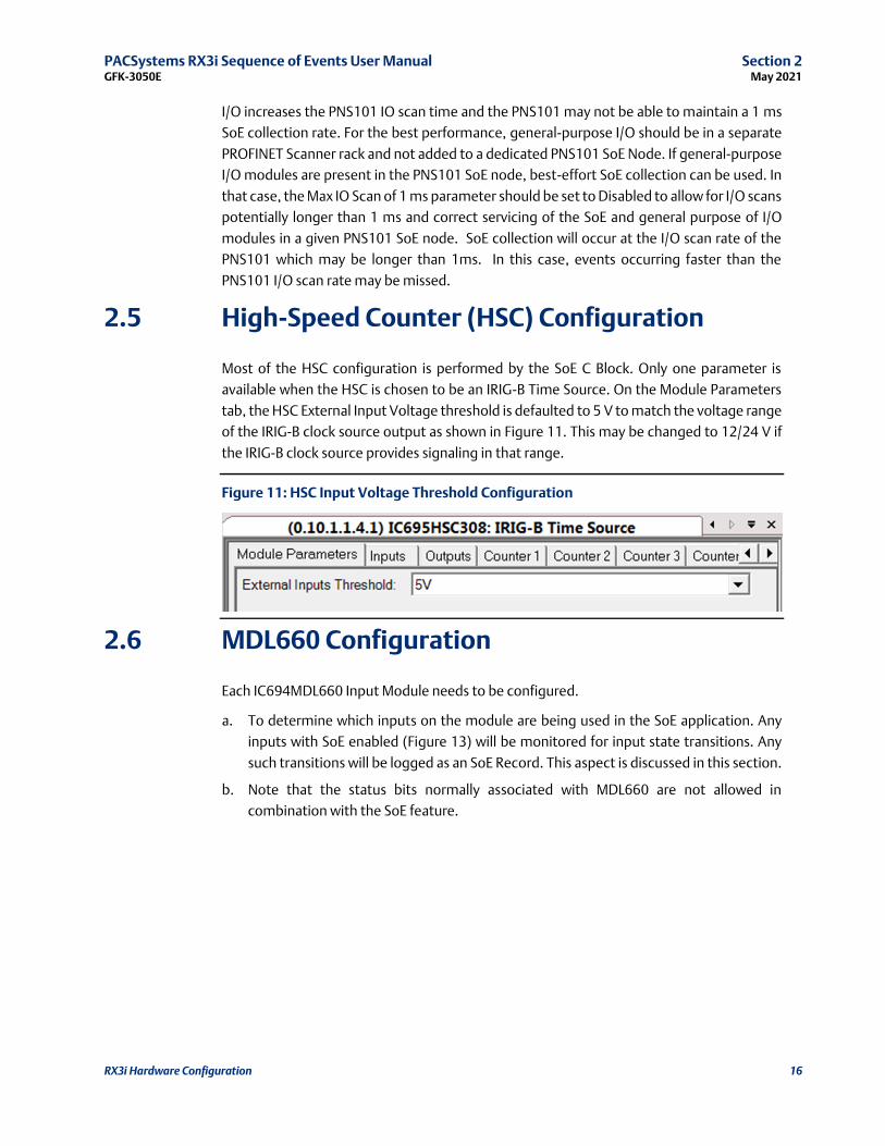
2.5 High-Speed Counter (HSC) Configuration
Most of the HSC configuration is performed by the SoE C Block. Only one parameter is
available when the HSC is chosen to be an IRIG-B Time Source. On the Module Parameters
tab, the HSC External Input Voltage threshold is defaulted to 5 V to match the voltage range
of the IRIG-B clock source output as shown in Figure 11. This may be changed to 12/24 V if
the IRIG-B clock source provides signaling in that range.
Figure 11: HSC Input Voltage Threshold Configuration
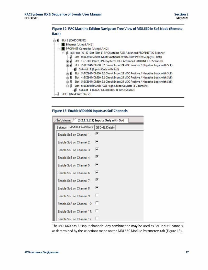
2.6 MDL660 Configuration
Each IC694MDL660 Input Module needs to be configured.
a. To determine which inputs on the module are being used in the SoE application. Any
inputs with SoE enabled (Figure 13) will be monitored for input state transitions. Any
such transitions will be logged as an SoE Record. This aspect is discussed in this section.
b. Note that the status bits normally associated with MDL660 are not allowed in
combination with the SoE feature.
PACSystems RX3i Sequence of Events User Manual Section 2 GFK-3050E May 2021
RX3i Hardware Configuration 17
Figure 12: PAC Machine Edition Navigator Tree View of MDL660 in SoE Node (Remote
Rack)
Figure 13: Enable MDL660 Inputs as SoE Channels
The MDL660 has 32 input channels. Any combination may be used as SoE Input Channels,
as determined by the selections made on the MDL660 Module Parameters tab (Figure 13).

PACSystems RX3i Sequence of Events User Manual Section 2 GFK-3050E May 2021
RX3i Hardware Configuration 18
2.7 MDL655 Configuration
Each IC694MDL655 Input Module needs to be configured.
To determine which inputs on the module are being used in the SoE application. Any inputs
with SoE enabled (Figure 14) will be monitored for input state transitions. Any such
transitions will be logged as an SoE Record. This aspect is discussed in this section.
Figure 14: PAC Machine Edition Navigator Tree View of MDL655 in SoE Node (Remote
Rack)
Figure 15: Enable MDL655 Inputs as SoE Channels
The MDL655 has 32 input channels. Any combination may be used as SoE Input Channels,
as determined by the selections made on the MDL655 Module Parameters tab (Figure 17).
PACSystems RX3i Sequence of Events User Manual Section 3 GFK-3050E May 2021
IRIG-B Setup & Interface 19
Section 3 IRIG-B Set-up & Interface
IRIG-B is a protocol used to encode Global Positioning System (GPS) time into a serial
bitstream. The RX3i architecture uses the IRIG-B data stream to synchronize its local clock
to that GPS Time. It then uses its locally synchronized clock as the time-source when an SoE
event is detected in the RX3i system.
The IRIG-B signal is physically interfaced to the RX3i SoE system via a BNC cable. The BNC
signal is connected to a series of High-Speed Counter (HSC) Modules, one located in each
SoE Node (Figure 1). Either an IC695HSC304 or an IC695HSC308 may be used.
The HSC module converts the IRIG-B signal to a digital bitstream that is delivered to the PNS
over the backplane. The PNS module interprets the bitstream to resynchronize its internal
time base once per second, which it subsequently uses to time-stamp all SoE events in the
same rack.
The time-stamped SoE records are stored by the PNS. The PNS then sets an SoE Data
Available status bit indication to the CPU. The CPU automatically retrieves the associated
SoE records over PROFINET and deposits those records into the memory location previously
configured for SoE Records (refer to Section 1)
The limiting factor for the overall accuracy of the time-stamp is the 1ms update rate of the
inputs on IC694MDL660/IC694MDL655 and the input filter delay of the IC694MDL655.
Refer to the PACSystems RX3i System Manual, GFK-2314 for information on how to set the
input filter to its lowest value on MDL660. This setting (0) corresponds to the hardware filter
of 0.5ms. The purpose of the input filter is to prevent unwanted transitions from external
electrical noise that may be present at the SoE Node,
The supported formats of the IRIG 200-04 standard are: B000, B004, B005, B006, and B007.
Instruments that use the older IRIG 200-98 standard are also supported in format B000 with
IEEE 1344-1995 control function extensions.
The solution can be configured to accept Unmodulated (DC Level) IRIG-B signals. Modulated
(1 kHz Carrier) signaling is not supported.

PACSystems RX3i Sequence of Events User Manual Section 3 GFK-3050E May 2021
IRIG-B Setup & Interface 20
3.1 Connecting the IRIG-B to HSC Input
Attach the BNC connector to the Unmodulated (DC Level) output connector on the IRIG-B
hardware, per your application design.
The IRIG-B Signal is connected to the HSC in each SoE Node on the network via BNC
breakout boxes, as indicated in Figure 15 One BNC breakout box is required for each SoE
Node in your application.
• Connect the positive signal from the BNC breakout box to Input 1 (Terminal 1) of the
HSC.
• Connect the BNC breakout box negative signal to the HSC Common terminal
(Terminal 9).
• Do not use any other HSC input for this purpose.
Figure 16: IRIG-B Signal Distribution
The following table documents the callouts shown in Figure 16. The indicated components
are available from multiple sources. The indicated vendor and corresponding components
are provided as a reference.
Item Part Number Description Vendor
1 2249-C-XX RG58 Patch Cable: (XX = length in inches) Pomona
2 3284 BNC Tee Pomona
3 4969 BNC Breakout Pomona

PACSystems RX3i Sequence of Events User Manual Section 3 GFK-3050E May 2021
IRIG-B Setup & Interface 21
Figure 17: Field Wiring HSC304
Figure 18: Field Wiring HSC308
The HSC module used for interfacing with the IRIG-B signal cannot perform any other
functions
Refer to the PACSystems RX3i System Manual, GFK-2314, Chapter 8, for information on
HSC304 & HSC308.
3.2 Synchronization of the CPU System Clock
TheCPU system clock is not synchronized to the IRIG-B signal.
PACSystems RX3i Sequence of Events User Manual Section 4 GFK-3050E May 2021
SoE/IRIG-B User Memory Map 22
Section 4 SoE/IRIG-B User Memory-Map
The second part of setup for an SoE operation is the SoE/IRIG-B User Memory-Map that the
SoE Application C Block will read.
The structure discussed in this section is set up in the PLC CPU Memory. It is manipulated by
the user to interface with the SoE application.
The SoE C-Block accepts an input that defines the base memory location for the structure.
Once the base location is set, all elements are relatively located, as shown below.
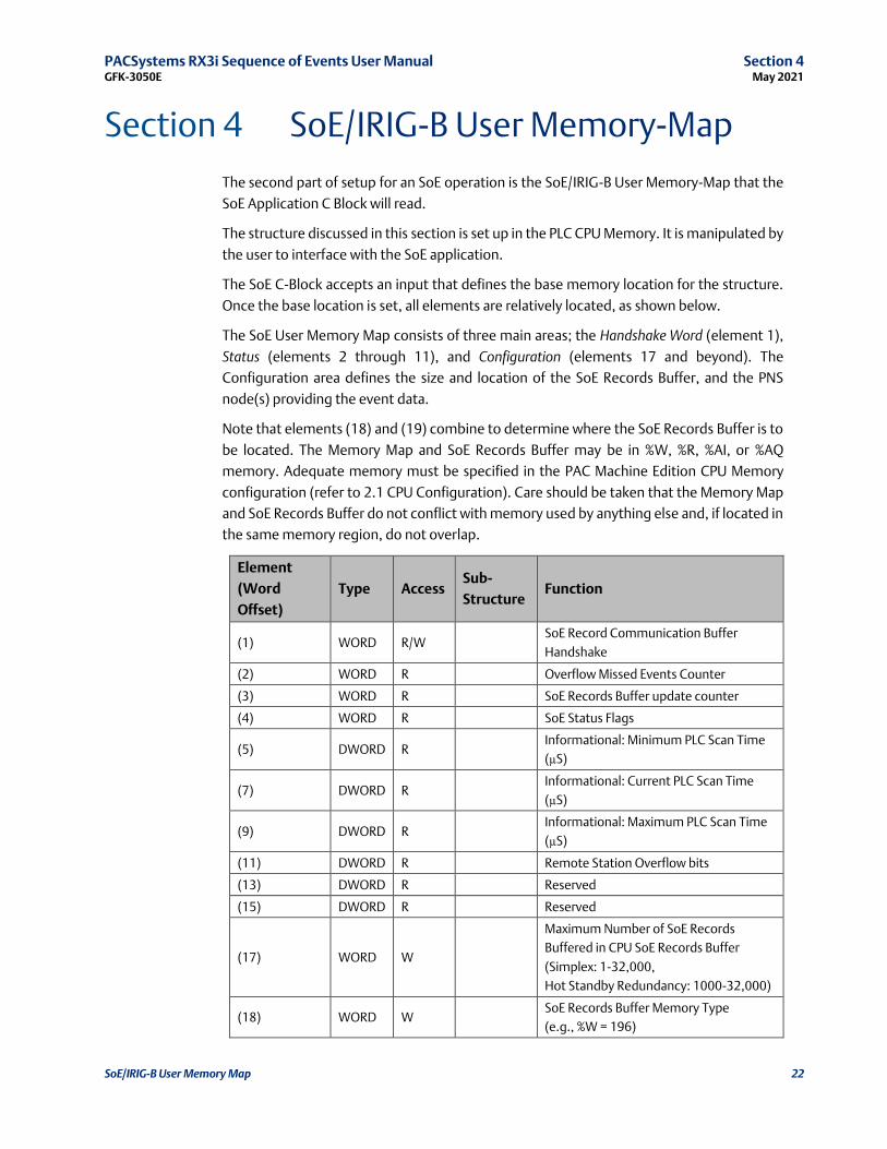
The SoE User Memory Map consists of three main areas; the Handshake Word (element 1),
Status (elements 2 through 11), and Configuration (elements 17 and beyond). The
Configuration area defines the size and location of the SoE Records Buffer, and the PNS
node(s) providing the event data.
Note that elements (18) and (19) combine to determine where the SoE Records Buffer is to
be located. The Memory Map and SoE Records Buffer may be in %W, %R, %AI, or %AQ
memory. Adequate memory must be specified in the PAC Machine Edition CPU Memory
configuration (refer to 2.1 CPU Configuration). Care should be taken that the Memory Map
and SoE Records Buffer do not conflict with memory used by anything else and, if located in
the same memory region, do not overlap.
Element
(Word
Offset)
Type Access Sub-
Structure Function
(1) WORD R/W SoE Record Communication Buffer
Handshake
(2) WORD R Overflow Missed Events Counter
(3) WORD R SoE Records Buffer update counter
(4) WORD R SoE Status Flags
(5) DWORD R Informational: Minimum PLC Scan Time
(µS)
(7) DWORD R Informational: Current PLC Scan Time
(µS)
(9) DWORD R Informational: Maximum PLC Scan Time
(µS)
(11) DWORD R Remote Station Overflow bits
(13) DWORD R Reserved
(15) DWORD R Reserved
(17) WORD W
Maximum Number of SoE Records
Buffered in CPU SoE Records Buffer
(Simplex: 1-32,000,
Hot Standby Redundancy: 1000-32,000)
(18) WORD W SoE Records Buffer Memory Type
(e.g., %W = 196)
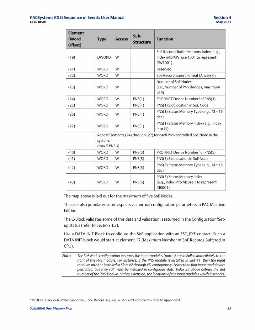
PACSystems RX3i Sequence of Events User Manual Section 4 GFK-3050E May 2021
SoE/IRIG-B User Memory Map 23
Element
(Word
Offset)
Type Access Sub-
Structure Function
(19) DWORD W
SoE Records Buffer Memory Index (e.g.,
Index into %W: use 1001 to represent
%W1001)
(21) WORD W Reserved
(22) WORD W SoE Record Export Format (Always 0)
(23) WORD W
Number of SoE Nodes
(i.e., Number of PNS devices, maximum
of 5)
(24) WORD W PNS(1) PROFINET Device Number4 of PNS(1)
(25) WORD W PNS(1) PNS(1) Slot location in SoE Node
(26) WORD W PNS(1) PNS(1) Status Memory Type (e.g., %I = 16
dec)
(27) WORD W PNS(1) PNS(1) Status Memory Index (e.g., index
into %I)
Repeat Elements (24) through (27) for each PNS-controlled SoE Node in the
system.
(max 5 PNS’s).
(40) WORD W PNS(5) PROFINET Device Number2 of PNS(5)
(41) WORD W PNS(5) PNS(5) Slot location in SoE Node
(42) WORD W PNS(5) PNS(5) Status Memory Type (e.g., %I = 16
dec)
(43) WORD W PNS(5)
PNS(5) Status Memory Index
(e.g., index into %I: use 1 to represent
%I0001)
The map above is laid out for the maximum of five SoE Nodes.
The user also populates some aspects via normal configuration parameters in PAC Machine
Edition.
The C-Block validates some of this data and validation is returned in the Configuration/Set-
up status (refer to Section 4.2).
Use a DATA INIT Block to configure the SoE application with an FST_EXE contact. Such a
DATA INIT block would start at element 17 (Maximum Number of SoE Records Buffered in
CPU).
Note: The SoE Node configuration assumes the input modules (max 4) are installed immediately to the right of the PNS module. For instance, if the PNS module is installed in Slot #1, then the input modules must be installed in Slots #2 through #5, contiguously. Fewer than four input modules are permitted, but they still must be installed in contiguous slots. Index 25 above defines the slot number of the PNS Module, and by extension, the locations of the input modules which it services.
4 PROFINET Device Number cannot be 0. SoE Record requires 1-127 (7-bit constraint – refer to Appendix A).
PACSystems RX3i Sequence of Events User Manual Section 4 GFK-3050E May 2021
SoE/IRIG-B User Memory Map 24
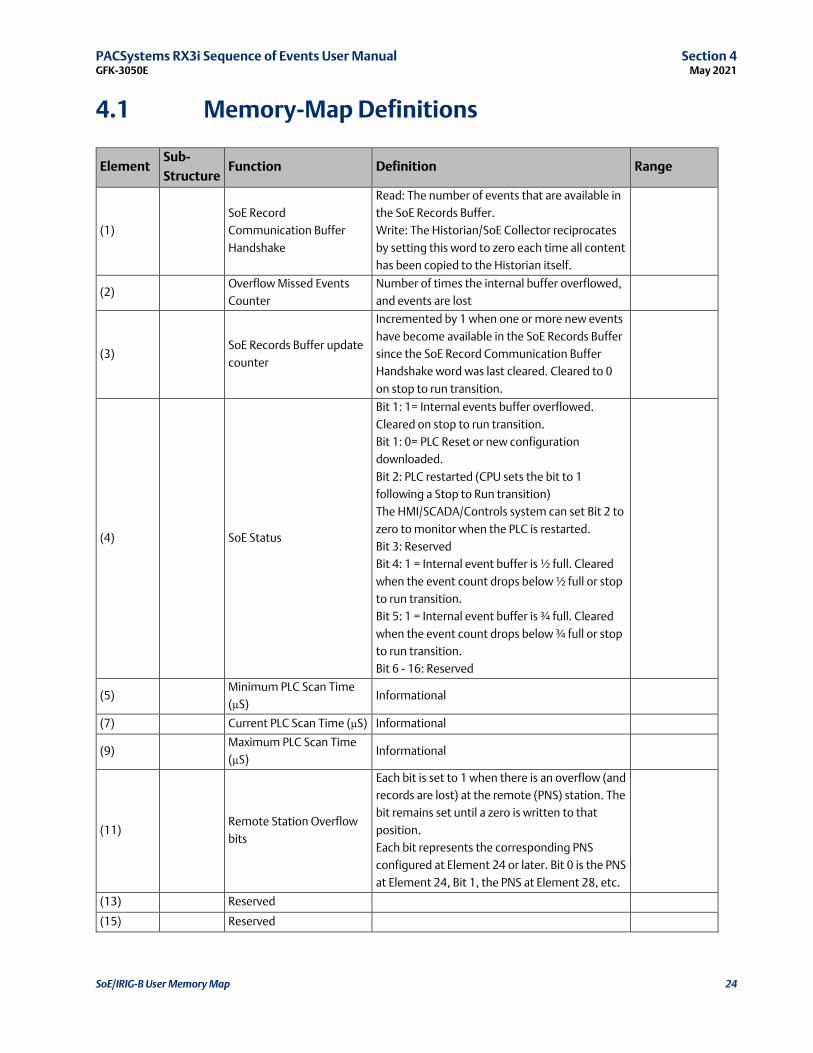
4.1 Memory-Map Definitions
Element Sub-
Structure Function Definition Range
(1)
SoE Record
Communication Buffer
Handshake
Read: The number of events that are available in
the SoE Records Buffer.
Write: The Historian/SoE Collector reciprocates
by setting this word to zero each time all content
has been copied to the Historian itself.
(2) Overflow Missed Events
Counter
Number of times the internal buffer overflowed,
and events are lost
(3) SoE Records Buffer update
counter
Incremented by 1 when one or more new events
have become available in the SoE Records Buffer
since the SoE Record Communication Buffer
Handshake word was last cleared. Cleared to 0
on stop to run transition.
(4) SoE Status
Bit 1: 1= Internal events buffer overflowed.
Cleared on stop to run transition.
Bit 1: 0= PLC Reset or new configuration
downloaded.
Bit 2: PLC restarted (CPU sets the bit to 1
following a Stop to Run transition)
The HMI/SCADA/Controls system can set Bit 2 to
zero to monitor when the PLC is restarted.
Bit 3: Reserved
Bit 4: 1 = Internal event buffer is ½ full. Cleared
when the event count drops below ½ full or stop
to run transition.
Bit 5: 1 = Internal event buffer is ¾ full. Cleared
when the event count drops below ¾ full or stop
to run transition.
Bit 6 - 16: Reserved
(5) Minimum PLC Scan Time
(µS) Informational
(7) Current PLC Scan Time (µS) Informational
(9) Maximum PLC Scan Time
(µS) Informational
(11) Remote Station Overflow
bits
Each bit is set to 1 when there is an overflow (and
records are lost) at the remote (PNS) station. The
bit remains set until a zero is written to that
position.
Each bit represents the corresponding PNS
configured at Element 24 or later. Bit 0 is the PNS
at Element 24, Bit 1, the PNS at Element 28, etc.
(13) Reserved
(15) Reserved

PACSystems RX3i Sequence of Events User Manual Section 4 GFK-3050E May 2021
SoE/IRIG-B User Memory Map 25
Element Sub-
Structure Function Definition Range
(17) Maximum Number of SoE
Records Buffered in CPU
The communication buffer in the CPU is
configurable to store up to 32,000 SoE Records.
This word indicates the maximum number of SoE
Records the host HMI/SCADA/Controls
Application Program can poll and collect.
By checking the information in the SoE Record
Communications Buffer Handshake word (1), the
SoE C-Block application in the CPU moves the
SoE Records from the internal buffer to the SoE
Records Buffer. Be aware that the larger the
number of SoE Records specified, the larger the
impact on the PLC scan time.
Each SoE Record is 10 words in size.
1--32,000
For
Redundancy,
the range is
1,000 –
32,000.
(18)
SoE Records Buffer
Memory Type
(%W, %R, %AI, or %AQ)
%W = 196 (dec),
%R = 8,
%AI = 10 (dec),
%AQ = 12 (dec)
Using %W is
recommended.
(19)
SoE Records Buffer
Memory Index
(i.e., Index into Memory
Type)
Enter 1001 to indicate %W1001, for example.
The range is
dependent on
memory type
and
configuration
maxima
(selected at
Index (18)
above).
(21) Reserved 0
(22) Export Format
This parameter is used to select the SoE Record
Format that will be used in the SoE Records
Buffer.
Always 0
(23)
Number of SoE Nodes
(i.e., Number of PNS
devices)
1-5
(24) PNS(1) PROFINET Device Number The range is limited by Export Format 1 - 127
(25) PNS(1) Slot occupied by PNS in
remote rack (SoE Node) slot #: 0 = slot 0… up to 0FH=Slot 15 0 - 15
(26) PNS(1) PNS Status Memory Type
(%I, %Q, %G, %M, %T)
For this memory type decimal value
%I Discrete input table (Byte mode) 16
%Q Discrete output table (Byte mode) 18
%G Discrete G table 86
%M Discrete M table 76
%T Discrete T table 74
(27) PNS(1) PNS Status Memory Index
(e.g. index into %I) 1 represents %I0001
Repeat elements (24) through (27) for each PNS-controlled SoE Node in the system.
Refer to page 22.

PACSystems RX3i Sequence of Events User Manual Section 4 GFK-3050E May 2021
SoE/IRIG-B User Memory Map 26
4.2 Configuration/Set-up Status
The status reflected here is generated by the SoE C-Block. It is one word wide. Its location in
reference memory is determined by the CPU application program. See Rung 5 in the ladder
logic below (Figure 29).
Status Description
0 OK
-1 The SoE User Memory Location, supplied as a parameter to the C-Block is null, which is
not permitted. (This does not apply to the SoE Status parameter, which may be null).
-2 The memory type used for the SoE Memory-Map is not supported.
Supported types are %W, %R, %AI, and %AQ.
-3 The SoE User Memory Location supplied as a parameter to the C Block is set to a
Memory Type configured for a memory size of 0.
-4 SoE Memory-Map will not fit in the available memory. Either there is insufficient
memory configured or the 151-word map is not within the available memory range.
-5 Unsupported SoE record format. Check the contents of the Export Format element in
the Memory Map.
-6 The memory index used for the SoE Records Buffer is zero. All CPU memory is 1-based,
e.g. %W0001, etc.
-7 Memory Type used for the SoE Records Buffer is not supported. Supported types are
%W, %R, %AI, and %AQ.
-8
SoE Records Buffer, as configured, will not fit in the available memory. There is
insufficient memory configured for the specified memory, or it is located such that it
does not fit in the range of available memory.
-9
SoE Records Buffer size has been set to default. This happens when the user inputs a
size of zero or a value greater than the maximum (32,000). The default value is 50
events. This error code may be ignored; the code is displayed but the C Block call will
pass power.
-10 SoE Records Buffer update delay value is not supported and must be set to zero.
-11 SoE Records Bufferstarts within the SoE Memory-Map area.
-12 SoE Records Buffer overlaps the SoE Memory-Map area.
-13 Invalid number of Remote Nodes. Valid values are 1 through 32.
-14
Applying the SoE configuration has failed. Ensure the CPU firmware version supports
the SoE C Block. (Requires CPE330 version 9.60 or later. Requires CPE400/CPL410
version 10.10 or later.)
-15 Failed to collect SoE Records from the CPU.
-16 User configured Comm Buffer Event Size is less than minimum required for redundant
mode (1000 events)
-1xx
Invalid Device Number. Error numbers are in the range -101 to -132.
An unsupported Device Number was specified in the indicated PNS record (1-32). The
PNS Device Number must be in the range of 1 – 127.

PACSystems RX3i Sequence of Events User Manual Section 4 GFK-3050E May 2021
SoE/IRIG-B User Memory Map 27
Status Description
-2xx
Invalid Remote Node Status Memory Type. Error numbers are in the range -201 to -
232.
An unsupported reference address memory type was specified in the indicated PNS
record (1-32).
-3xx
Invalid Remote Node Status Memory Index. Error numbers are in the range -301 to -
332.
An invalid reference address was specified in the indicated PNS record (1-32).
4.3 Configuration Errors
Some setup or configuration errors in an SoE system are only detected when the SoE
application has been stored and the CPU is put in run mode. These errors are reported in the
CPU Fault Table. The presence of any of these faults indicates the SoE system is not
configured correctly and the system will not collect and report all Events.
These errors are caused by incorrect data in one or more of the four-word SoE Node
descriptors, starting at element 24 in the User Memory-Map (section 4.1 Memory-Map
Definitions). If one of these errors occurs, review the SoE Node PNS descriptors and correct
them as necessary. Changes are applied by storing the updated logic and putting the CPU
in Run mode.
Note that all Fault Extra Data is in hexadecimal format.
4.3.1 Invalid Device Number (Error Code 662)
The fault shown below is the result of providing an SoE Node Profinet Device Number that
does not exist in the hardware configuration of the PAC Machine Edition project.
Figure 19: PLC Fault Table
Figure 20: PACSAnalyzer Output
In the above example, PROFINET Device Number 3 as indicated in the fault extra data (9th
byte) has been specified for an SoE Node but does not exist in the hardware configuration

PACSystems RX3i Sequence of Events User Manual Section 4 GFK-3050E May 2021
SoE/IRIG-B User Memory Map 28
of the PAC Machine Edition project. Determine the correct PNS Device Number in the
hardware configuration for the project, find the corresponding SoE Node descriptor, and
replace it with the correct value.
4.3.2 Collector Access Denied (Error Code 663)
The fault shown below may occur if a collector record request has been refused by an SoE
Node. The ninth byte of the Fault Extra Data is the SoE Node descriptor index in the Memory-
Map (section 4.1 Memory-Map Definitions) for the device being accessed when the failure
occurred. In the example below the error occurred while accessing the SoE Node defined by
the descriptor at index 0, i.e. the descriptor starting at element 24. Verify that the correct
slot location has been specified in the SoE Node descriptor.
Figure 21: PLC Fault Table
Figure 22: PACSAnalyzer Output
PACSystems RX3i Sequence of Events User Manual Section 5 GFK-3050E May 2021
Operation 29
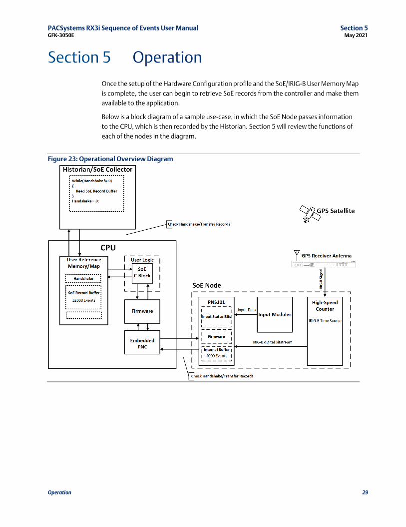
Section 5 Operation
Once the setup of the Hardware Configuration profile and the SoE/IRIG-B User Memory Map
is complete, the user can begin to retrieve SoE records from the controller and make them
available to the application.
Below is a block diagram of a sample use-case, in which the SoE Node passes information
to the CPU, which is then recorded by the Historian. Section 5 will review the functions of
each of the nodes in the diagram.
Figure 23: Operational Overview Diagram
PACSystems RX3i Sequence of Events User Manual Section 5 GFK-3050E May 2021
Operation 30
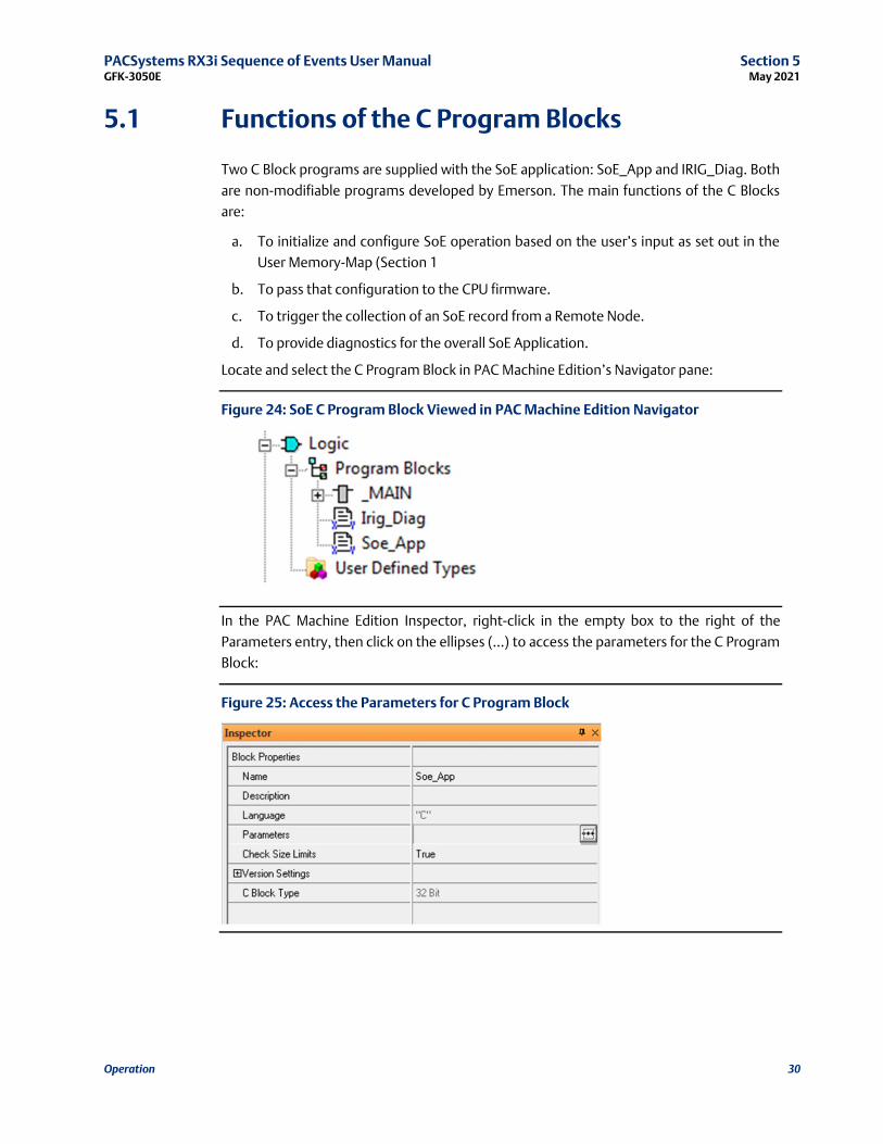
5.1 Functions of the C Program Blocks
Two C Block programs are supplied with the SoE application: SoE_App and IRIG_Diag. Both
are non-modifiable programs developed by Emerson. The main functions of the C Blocks
are:
a. To initialize and configure SoE operation based on the user’s input as set out in the
User Memory-Map (Section 1
b. To pass that configuration to the CPU firmware.
c. To trigger the collection of an SoE record from a Remote Node.
d. To provide diagnostics for the overall SoE Application.
Locate and select the C Program Block in PAC Machine Edition’s Navigator pane:
Figure 24: SoE C Program Block Viewed in PAC Machine Edition Navigator
In the PAC Machine Edition Inspector, right-click in the empty box to the right of the
Parameters entry, then click on the ellipses (…) to access the parameters for the C Program
Block:
Figure 25: Access the Parameters for C Program Block

PACSystems RX3i Sequence of Events User Manual Section 5 GFK-3050E May 2021
Operation 31
5.1.1 Set up the Input and Output Parameters for the C
Program Block
The SoE_App C Program Block requires one input parameter and supplies two output
parameters:
1. INPUT - SoE User Memory Location (WORD). This parameter is pointing to the base
of the SoE User Memory Map discussed in Section 1. Enter a memory reference such
as %W0001. Note that the corresponding memory area cannot be used for any
other purpose once assigned to the SoE Application.
2. OUTPUT - Configuration Status (INT). The C-Block uses this parameter to indicate
the status of the SoE application operations, per section 4.2. Zero indicates OK.
Negative values indicate various error conditions. This parameter may be null, but
null is not recommended, as status information would not then be relayed to the
user.
3. OUTPUT – SoE C-Block Version (WORD): for information only. Should any interfaces
change over time, they may be traced to this item.
Figure 26: C Program Block Input Parameters

PACSystems RX3i Sequence of Events User Manual Section 5 GFK-3050E May 2021
Operation 32
Figure 27: C Program Block Output Parameters
5.1.2 Install Ladder Logic in Support of C-Block
Once the User Memory-Map (refer to Section 4) and the Input and Output Parameters
discussed above have been set up, install ladder logic (or equivalent) to initialize the SoE
execution, using a Data Init Function Block, as shown in
Figure 28 (rung 3). The Data Init function is used to populate user configuration data in the
SoE Memory Map that begins at Element 17. This should be executed only once.
Figure 28: Data Init Function Block for SoE_App Set-up (Rung 3)
The first word of the SoE User Memory-Map is the SoE Record Communications Buffer
Handshake word. The C Block updates this word with the number of events that have been
copied to the SoE Records Buffer. When the buffer is populated, no more events are written.
Writing zero to this word causes the Controller to start re-filling the capture buffer from the
start.

PACSystems RX3i Sequence of Events User Manual Section 5 GFK-3050E May 2021
Operation 33
The next 6 parameters provide SoE status information and are updated continuously while
the C Block is being executed.
The parameters starting at word 17 provide SoE configuration data to the Controller. These
are read by the SoE C Block and updated to the CPU on stop-to-run transitions only.
Following initialization, the C Program Block is called on every subsequent Logic Scan.
Figure 29: Calling SoE_App C Program Block from Main Program (Rung 5)
5.2 Functions of the Input Modules
(MDL660/MDL655)
The input module MDL660 or MDL655 is scanned in the normal way by the PROFINET
Scanner (PNS) located in the same rack. For those inputs which have been designated as SoE
Channels (refer to Section 2.6, MDL660 Configuration or Section 2.7 MDL655
Configuration), an SoE event is logged whenever a transition is detected on a corresponding
input.
5.3 Functions of the High-Speed Counter (HSC)
Each High-Speed Counter Module converts the GPS Time IRIG-B data stream to a digital data
stream to be interpreted by the PNS.
Note that the functionality of the HSC is constrained by the GSMDL file used in this
application. Only the IRIG-B input is operational.

PACSystems RX3i Sequence of Events User Manual Section 5 GFK-3050E May 2021
Operation 34
5.4 Functions of the Advanced PROFINET Scanner
(PNS101)
The PROFINET Scanner executes several functions:
a. Interprets the data stream from the HSC to synchronize the SoE Node time-base
once per second.
b. Read inputs from the IC694MDL660’s or IC694MDL655’s in the rack. If the PNS is
configured for a Max IO Scan of 1ms, then priority is given to reading the
MDL660/MDL655’s every 1ms so events can be recognized every ms.
c. Based on the configuration received during initialization, it analyzes the inputs from
the SoE-enabled channels of the MDL660/MDL655 modules located in the same rack
and generates an SoE time-stamped record whenever a transition is detected on one
of those channels.
d. Once PNS101 is initialized, config received, and is ready to record events, any input
that is already in a high state will be recorded as a new event.
e. It generates an IRIG-B time processing status.
f. In response to periodic requests from its host CPU, the PNS passes the SoE records to
its host over the PROFINET bus.
PACSystems RX3i Sequence of Events User Manual Section 5 GFK-3050E May 2021
Operation 35
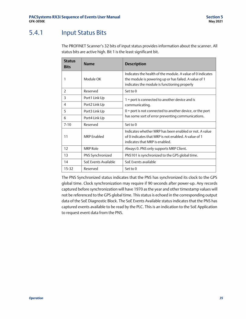
5.4.1 Input Status Bits
The PROFINET Scanner’s 32 bits of input status provides information about the scanner. All
status bits are active high. Bit 1 is the least significant bit.
Status
Bits Name Description
1 Module OK
Indicates the health of the module. A value of 0 indicates
the module is powering up or has failed. A value of 1
indicates the module is functioning properly
2 Reserved Set to 0
3 Port1 Link Up 1 = port is connected to another device and is
communicating.
0 = port is not connected to another device, or the port
has some sort of error preventing communications.
4 Port2 Link Up
5 Port3 Link Up
6 Port4 Link Up
7-10 Reserved Set to 0
11 MRP Enabled
Indicates whether MRP has been enabled or not. A value
of 0 indicates that MRP is not enabled. A value of 1
indicates that MRP is enabled.
12 MRP Role Always 0. PNS only supports MRP Client.
13 PNS Synchronized PNS101 is synchronized to the GPS global time.
14 SoE Events Available SoE Events available
15-32 Reserved Set to 0
The PNS Synchronized status indicates that the PNS has synchronized its clock to the GPS
global time. Clock synchronization may require if 90 seconds after power-up. Any records
captured before synchronization will have 1970 as the year and other timestamp values will
not be referenced to the GPS global time. This status is echoed in the corresponding output
data of the SoE Diagnostic Block. The SoE Events Available status indicates that the PNS has
captured events available to be read by the PLC. This is an indication to the SoE Application
to request event data from the PNS.
PACSystems RX3i Sequence of Events User Manual Section 5 GFK-3050E May 2021
Operation 36
5.5 Functions of the PROFINET Controller (PNC)
In addition to its role as a normal PROFINET Bus Controller, the CPU Embedded PNC retrieves
SoE data from all the configured SoE Nodes and interfaces with its host PACSystems
Controller (CPE330/CPE400/CPL410).
During initialization, it passes configuration information to each PROFINET Scanner, as
appropriate for that PNS101.
5.6 Functions of the CPU
The CPU interfaces with the C Program Block and with the Embedded PROFINET Controller
(PNC).
a. It processes the Configuration represented in the User Memory-Map (Section 1and
passes that configuration information to the PNC, which in turn, passes segments to
each PNS, as appropriate.
b. Based on PNS Status information, it initiates the collection of SoE records from each
SoE Node via the PNC and accumulates them for retrieval by the Historian/SoE
Collector.
c. Whenever the SoE Communication Buffer Handshake Word is zero, the CPU
transfers SoE Records from the internal SoE Records Buffer to the Communication
Buffer per the user-supplied configuration (Section 1).
d. The CPU monitors whether the internal SoE Records Buffer is full. In response to a full
condition, the more recent SoE records are lost and a diagnostic is produced (Section
6).
5.7 Functions of a Historian/SoE Collector
A Historian/SoE Collector interfaces with the CPU using an agreed protocol, such as SRTP,
EGD.
a. Whenever the SoE Record Communications Buffer Handshake Word is non-zero, the
Historian/SoE Collector reads the contents of the SoE Records Buffer from the CPU
for that number of records.
b. Once all records have been transferred from the SoE Records Buffer, the
Historian/SoE Collector needs to set the SoE Record Communications Handshake
Word to zero, as that action tells the CPU that the buffer is available for the update
again.
c. The Historian/SoE Collector retains all SoE records collected in this fashion, in
conformance with rules established by its operator.
d. The Historian/SoE Collector then performs further SoE record analysis, as
programmed by its operator.
PACSystems RX3i Sequence of Events User Manual Section 5 GFK-3050E May 2021
Operation 37
5.8 Performance Considerations
For both Simplex and Redundant operation, each RX3i PNS101 device and each MDL
module in the PNS rack will contribute time to the IO Scan sweep impact. The IO scan sweep
impact is the same as non-SOE RX3i PNS001 devices and modules.
For Simplex (non-redundant) SOE operation, the SOE Application C-block has a logic
execution time that impacts CPU sweep time.
The SOE_Application logic execution time can be estimated as follows:
SOE_ Application Idle call: 0.02ms
SOE_ Application Update call: 0.75ms per 1000 events added to SoE Records Buffer
An Idle call occurs when the app is either waiting for the next SoE Record Communication
Buffer Handshake or there are no events in the internal buffer to move to the SoE Records
Buffer. An Update call occurs when the SOE Application updates the SoE Records Buffer with
new events.
The following formula estimates the SOE Application logic execution time for SoE Records
Buffer Update calls of at least 1000 events or more:
SoeAppExeTimeMilliseconds = (eventCnt * 0.00075)
Since the maximum SoE Records Buffer event size is 32000, the worst-case SOE Application
logic execution time is approximately 24ms. The worst-case logic execution impact can be
reduced by configuring the SoE Records Buffer for a smaller size. In most cases, the SOE
Application will be called in the Idle state so a minimal execution time will occur, but
periodically the SoE Records Buffer will be updated and that will result in a larger execution
time for that sweep.
For redundant SOE operation, the synchronization of buffered events from Active to Backup
is the primary contributor to sweep time. This sweep impact is dynamic and can change
from sweep-to-sweep depending on the number of events in the Internal buffer (not the
SoE Records Buffer in user memory). To keep the sweep impact to a minimum, the external
Historian/SOE Collector should empty the SoE Records Buffer at regular intervals and at a
rate that keeps up with the SOE event generation rate.
There can be additional sweep time impact due to the SoE Records Buffer data in the
Transfer List and the SOE_ Application C-Block execution time. For the SoE Records Buffer
data in the Transfer List, the sweep impact is constant each sweep. The sweep impact can
be minimized by using a smaller SoE RecordsBuffer. Allowed redundant SoE Records Buffer
sizes are between 1000 and 32000, so a size closer to 1000 will reduce the Transfer List sync
time. For the SOE_ Application C-Block, the logic execution times are equal to the
simplex/non-redundant times. However, when the SOE_ Application moves events from
the internal buffer to the SoE Records Buffer the sweep time will likely be reduced because
the impact due to synchronizing events in the internal buffer is greater than the SOE_
Application logic execution time to move events to the SoE Records Buffer.
PACSystems RX3i Sequence of Events User Manual Section 5 GFK-3050E May 2021
Operation 38
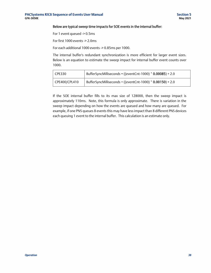
Below are typical sweep time impacts for SOE events in the internal buffer:
For 1 event queued -> 0.5ms
For first 1000 events -> 2.0ms
For each additional 1000 events -> 0.85ms per 1000.
The internal buffer's redundant synchronization is more efficient for larger event sizes.
Below is an equation to estimate the sweep impact for internal buffer event counts over
1000.
CPE330 BufferSyncMilliseconds = ((eventCnt-1000) * 0.00085) + 2.0
CPE400/CPL410 BufferSyncMilliseconds = ((eventCnt-1000) * 0.00150) + 2.0
If the SOE internal buffer fills to its max size of 128000, then the sweep impact is
approximately 110ms. Note, this formula is only approximate. There is variation in the
sweep impact depending on how the events are queued and how many are queued. For
example, if one PNS queues 8 events this may have less impact than 8 different PNS devices
each queuing 1 event to the internal buffer. This calculation is an estimate only.
PACSystems RX3i Sequence of Events User Manual Section 6 GFK-3050E May 2021
Diagnostics 39
Section 6 Diagnostics
The SoE system drops the more recent events once the Internal Events Buffer overflows.
There are indications that the buffer has overflowed in the memory map. Refer to the SoE
Status Byte, bit 1 (Section 4.1, Memory-Map Definitions). Each SoE Node also has an
Overflow bit in the Remote Station Overflow bits status register.
The IRIG_Diag C-Block is used to collect diagnostic info from the configured SoE devices.
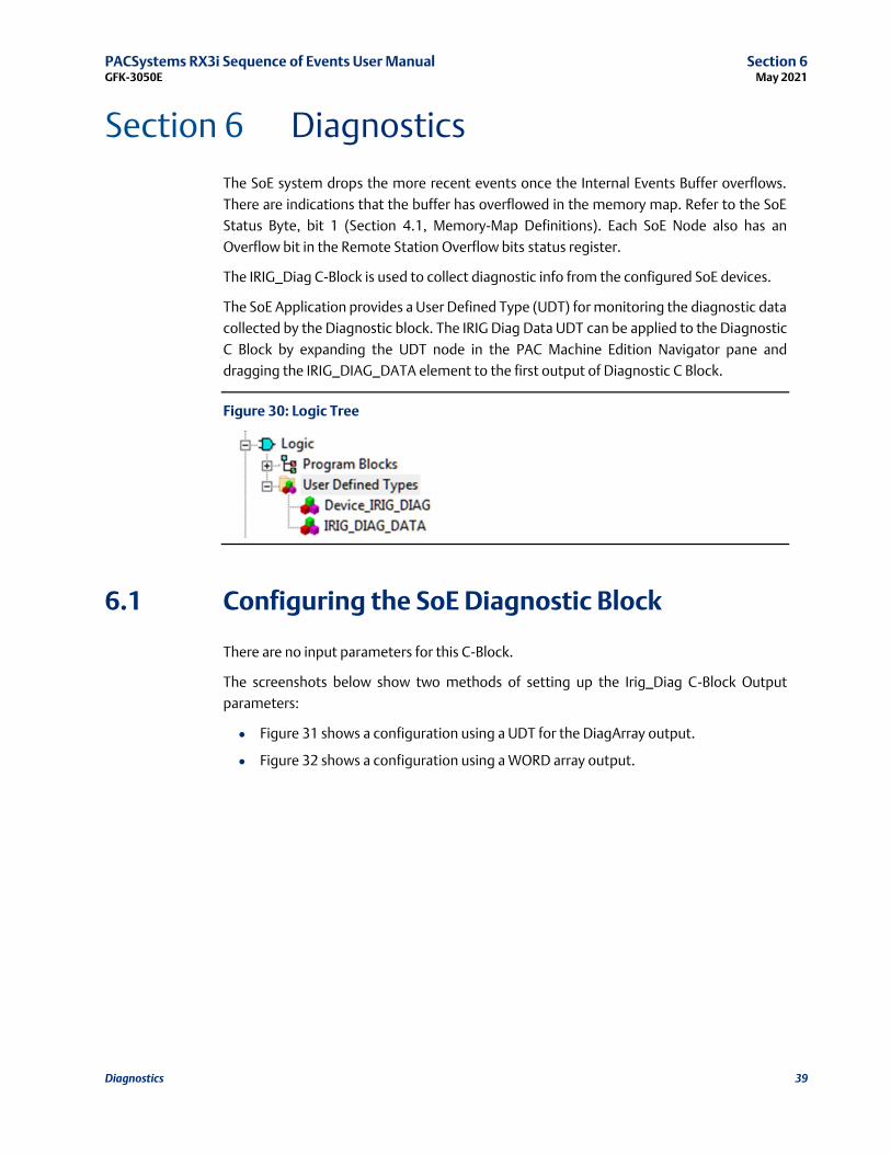
The SoE Application provides a User Defined Type (UDT) for monitoring the diagnostic data
collected by the Diagnostic block. The IRIG Diag Data UDT can be applied to the Diagnostic
C Block by expanding the UDT node in the PAC Machine Edition Navigator pane and
dragging the IRIG_DIAG_DATA element to the first output of Diagnostic C Block.
Figure 30: Logic Tree
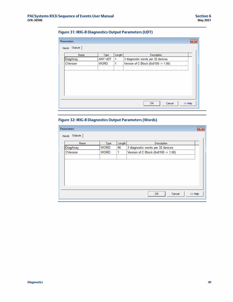
6.1 Configuring the SoE Diagnostic Block
There are no input parameters for this C-Block.
The screenshots below show two methods of setting up the Irig_Diag C-Block Output
parameters:
• Figure 31 shows a configuration using a UDT for the DiagArray output.
• Figure 32 shows a configuration using a WORD array output.
PACSystems RX3i Sequence of Events User Manual Section 6 GFK-3050E May 2021
Diagnostics 40
Figure 31: IRIG-B Diagnostics Output Parameters (UDT)
Figure 32: IRIG-B Diagnostics Output Parameters (Words)

PACSystems RX3i Sequence of Events User Manual Section 6 GFK-3050E May 2021
Diagnostics 41
6.2 Monitoring SoE Diagnostics
The IRIG-B diagnostics cannot be run on the first PLC scan, since the first scan is used to
configure the SoE system. The diagnostics application requires that the SoE system be
configured before it can query the PNS for diagnostic data. Any subsequent execution can
run the diagnostics, as shown in Figure 33.
Figure 33: SoE Diagnostic Monitoring
PACSystems RX3i Sequence of Events User Manual Section 6 GFK-3050E May 2021
Diagnostics 42
6.2.1 SoE Diagnostic Definitions
Device Id PNS device ID
Interrupt Per Sec Set to the number of IRIG-B interrupts the PNS is detecting
Un Modulated Status Set to true if the correct number of interrupts are seen for
an unmodulated IRIG-B signal
Modulated Status Set to true if the correct number of interrupts is seen for a
modulated IRIG-B signal
Time Quality Exceeded Set to true if IRIG-B packet IEEE-1344 extension time
quality value is above 6
Packet Error Set to true if last IRIG-B packet had an error of some kind
Connect Error Set to true if no IRIG-B interrupts seen in the last second
Clock Synced Set to true if the PNS has synchronized its internal clock to
match the IRIG-B clock
PACSystems RX3i Sequence of Events User Manual Appendix A GFK-3050E May 2021
Appendix A 43
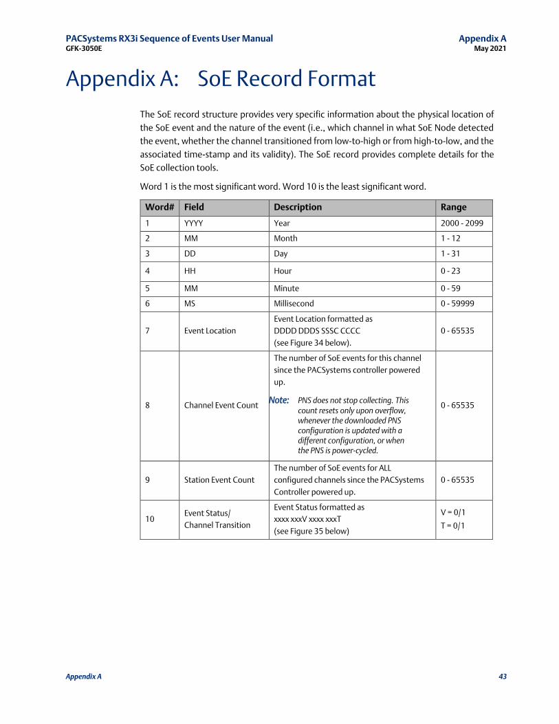
Appendix A: SoE Record Format
The SoE record structure provides very specific information about the physical location of
the SoE event and the nature of the event (i.e., which channel in what SoE Node detected
the event, whether the channel transitioned from low-to-high or from high-to-low, and the
associated time-stamp and its validity). The SoE record provides complete details for the
SoE collection tools.
Word 1 is the most significant word. Word 10 is the least significant word.
Word# Field Description Range
1 YYYY Year 2000 - 2099
2 MM Month 1 - 12
3 DD Day 1 - 31
4 HH Hour 0 - 23
5 MM Minute 0 - 59
6 MS Millisecond 0 - 59999
7 Event Location
Event Location formatted as
DDDD DDDS SSSC CCCC
(see Figure 34 below).
0 - 65535
8 Channel Event Count
The number of SoE events for this channel
since the PACSystems controller powered
up.
Note: PNS does not stop collecting. This count resets only upon overflow, whenever the downloaded PNS configuration is updated with a different configuration, or when the PNS is power-cycled.
0 - 65535
9 Station Event Count
The number of SoE events for ALL
configured channels since the PACSystems
Controller powered up.
0 - 65535
10 Event Status/
Channel Transition
Event Status formatted as
xxxx xxxV xxxx xxxT
(see Figure 35 below)
V = 0/1
T = 0/1
PACSystems RX3i Sequence of Events User Manual Appendix A GFK-3050E May 2021
Appendix A 44
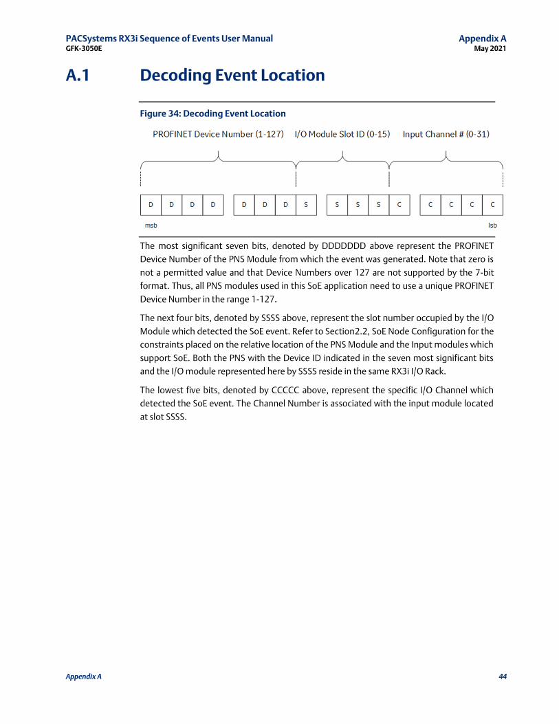
A.1 Decoding Event Location
Figure 34: Decoding Event Location
The most significant seven bits, denoted by DDDDDDD above represent the PROFINET
Device Number of the PNS Module from which the event was generated. Note that zero is
not a permitted value and that Device Numbers over 127 are not supported by the 7-bit
format. Thus, all PNS modules used in this SoE application need to use a unique PROFINET
Device Number in the range 1-127.
The next four bits, denoted by SSSS above, represent the slot number occupied by the I/O
Module which detected the SoE event. Refer to Section2.2, SoE Node Configuration for the
constraints placed on the relative location of the PNS Module and the Input modules which
support SoE. Both the PNS with the Device ID indicated in the seven most significant bits
and the I/O module represented here by SSSS reside in the same RX3i I/O Rack.
The lowest five bits, denoted by CCCCC above, represent the specific I/O Channel which
detected the SoE event. The Channel Number is associated with the input module located
at slot SSSS.
PACSystems RX3i Sequence of Events User Manual Appendix A GFK-3050E May 2021
Appendix A 45
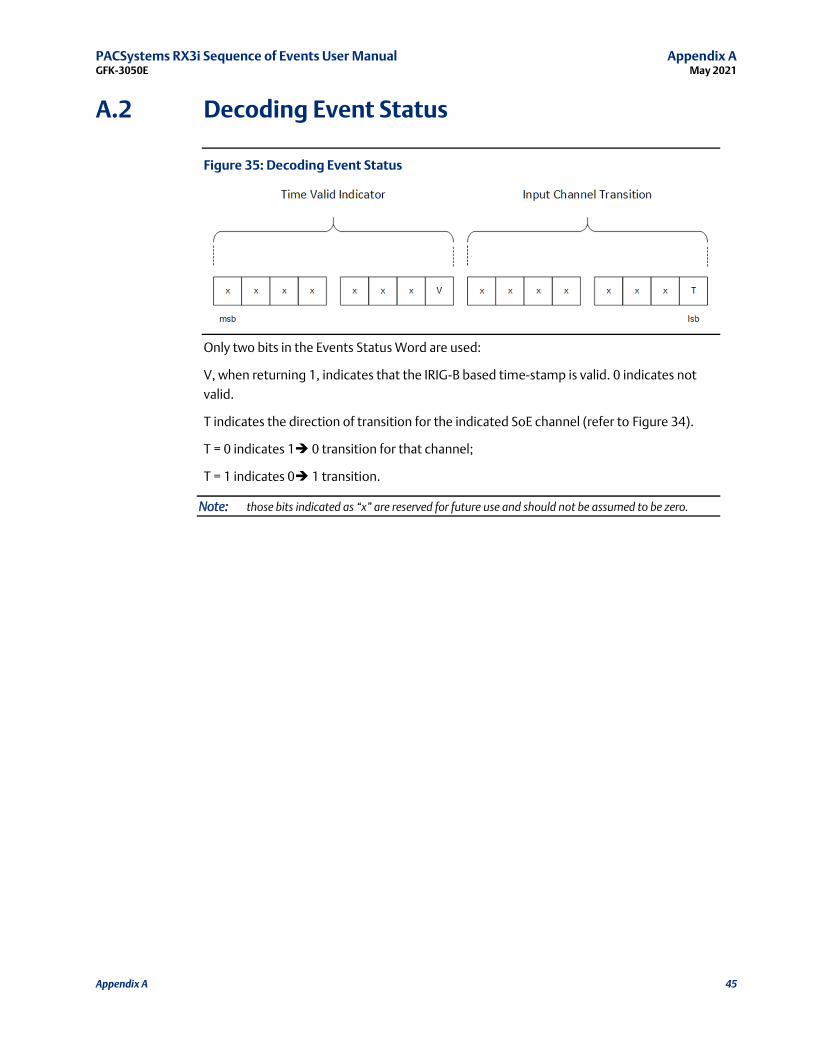
A.2 Decoding Event Status
Figure 35: Decoding Event Status
Only two bits in the Events Status Word are used:
V, when returning 1, indicates that the IRIG-B based time-stamp is valid. 0 indicates not
valid.
T indicates the direction of transition for the indicated SoE channel (refer to Figure 34).
T = 0 indicates 1➔ 0 transition for that channel;
T = 1 indicates 0➔ 1 transition.
Note: those bits indicated as “x” are reserved for future use and should not be assumed to be zero.

PACSystems RX3i Sequence of Events User Manual Appendix B GFK-3050E May 2021
Appendix B 46
Appendix B: Duplication of Events
The SoE implementation attempts to minimize or eliminate the possibility of duplicated
events, but there are some situations where duplication of events may still occur.
If a PNS sends SoE records to the CPU, but the PNS becomes disconnected before the CPU
acknowledges the events. Then the events will remain in the PNS device's event queue.
When the PNS device connection is later reestablished, the events previously sent to the
CPU may be repeated.
In a redundant system with SoE, Active status may switch between Primary and Secondary
units along with the Redundant IP assignment. If the external Historian/SoE Collector sets
the SoE Record Communication Buffer Handshake word to 0 just before a switch of Active
units, then the updated SoE Record Communication Buffer Handshake value may not get
transferred to the new Active unit. When the Redundant IP moves to the new Active unit,
the Historian/SoE Collector will see the SoE Record Communication Buffer Handshake at its
previous value and not cleared to 0. Thus, the Historian/SoE Collector may interpret this as
new events, but these records are the same events it previously consumed. This situation
can be avoided if the Historian/SoE Collector takes the extra step of also checking the SoE
Records Buffer update counter. If the update counter is the same value as the previously
consumed events, then the Historian/SoE Collector could write the SoE Record
Communication Buffer Handshake to 0 again and wait for a non-zero value.

PACSystems RX3i Sequence of Events User Manual Appendix C GFK-3050E May 2021
Appendix C 47
Appendix C: SoE Data Retrieval Example
The following example demonstrates the operation of a simplex SoE configuration with a
single PNS node. This sections uses an example application for PAC Machine Edition
application that is available in the Workshop_SOE.zip, which is included in the SoE
Application Software Bundle (Figure 36). This software bundle can be found on Emerson’s
support site (links are provided at the end of this document.) The HMI (QuickPanel+)
demonstrates a Run in Simulation mode on PAC Machine Edition View.
Figure 36: PROFINET SoE Application Software
Figure 37:Sample Block Diagram of a SOE Data Retrieval Solution
SoE Node
HMI PAC Machine Edition
IRIG
-B S
ign
al
GPS Satellite
IRIG-B Clock
PACSystems RX3i Sequence of Events User Manual Appendix C GFK-3050E May 2021
Appendix C 48
C.1 Preparing the RX3i Controller
Before the controller can retrieve SoE records, the target controller must be prepared to
maintain SoE information locally for applications requiring real-time decisions based on
the logged data.
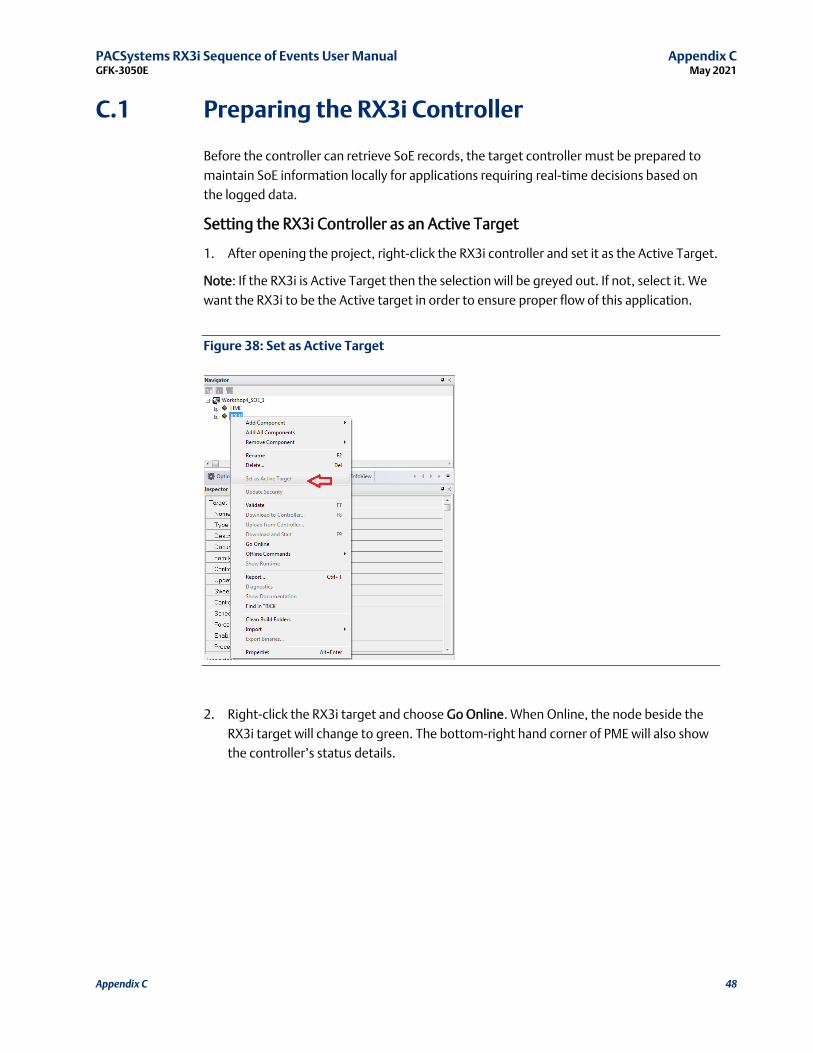
Setting the RX3i Controller as an Active Target
1. After opening the project, right-click the RX3i controller and set it as the Active Target.
Note: If the RX3i is Active Target then the selection will be greyed out. If not, select it. We
want the RX3i to be the Active target in order to ensure proper flow of this application.
Figure 38: Set as Active Target
2. Right-click the RX3i target and choose Go Online. When Online, the node beside the
RX3i target will change to green. The bottom-right hand corner of PME will also show
the controller’s status details.
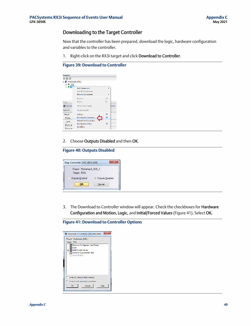
PACSystems RX3i Sequence of Events User Manual Appendix C GFK-3050E May 2021
Appendix C 49
Downloading to the Target Controller
Now that the controller has been prepared, download the logic, hardware configuration
and variables to the controller.
1. Right-click on the RX3i target and click Download to Controller.
Figure 39: Download to Controller
2. Choose Outputs Disabled and then OK.
Figure 40: Outputs Disabled
3. The Download to Controller window will appear. Check the checkboxes for Hardware
Configuration and Motion, Logic, and Initial/Forced Values (Figure 41). Select OK.
Figure 41: Download to Controller Options

PACSystems RX3i Sequence of Events User Manual Appendix C GFK-3050E May 2021
Appendix C 50
4. Right-click the target RX3i controller, navigate to Online Commands, and start the
controller (Figure 42).
Figure 42: Restart the Controller
5. Select Outputs Enabled and OK.
Figure 43: Outputs Enabled
6. Ensure the status in the bottom-right looks like Figure 44.
Figure 44: Controller is running

PACSystems RX3i Sequence of Events User Manual Appendix C GFK-3050E May 2021
Appendix C 51
C.2 Reviewing Downloaded Logic, Hardware
Configuration, and Initial/Forced Values
This section shows the user how to review and edit the three download outputs from the
previous section. While the sample application in the ZIP file is functional, it is only meant
to serve for illustrative purposes and users will need to customize the logic, hardware
configuration (HWC), and variables to suit their needs.
To begin, we need to view the logic that was downloaded to the controller in the previous
section.
Viewing the Logic
1. Open the Program Blocks node to reveal _MAIN.
2. Double-click the _MAIN Ladder Diagram node so that the InfoViewer looks like Figure
45.
Figure 45: _MAIN Ladder Diagram
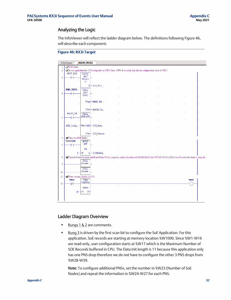
PACSystems RX3i Sequence of Events User Manual Appendix C GFK-3050E May 2021
Appendix C 52
Analyzing the Logic
The InfoViewer will reflect the ladder diagram below. The definitions following Figure 46,
will describe each component.
Figure 46: RX3i Target
Ladder Diagram Overview
▪ Rungs 1 & 2 are comments.
▪ Rung 3 is driven by the first scan bit to configure the SoE Application. For this
application, SoE records are starting at memory location %W1000. Since %W1-W16
are read-only, user configuration starts at %W17 which is the Maximum Number of
SOE Records buffered in CPU. The Data Init length is 11 because this application only
has one PNS drop therefore we do not have to configure the other 3 PNS drops from
%W28-W39.
Note: To configure additional PNSs, set the number in %W23 (Number of SoE
Nodes) and repeat the information in %W24-W27 for each PNS.
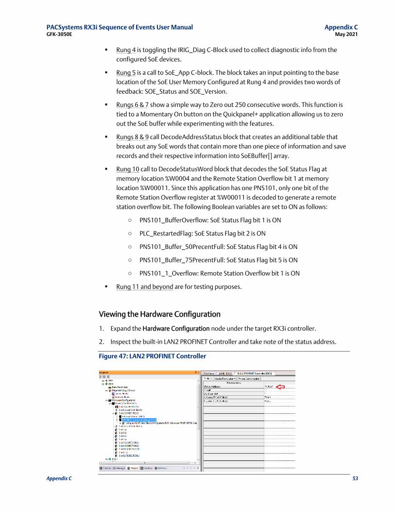
PACSystems RX3i Sequence of Events User Manual Appendix C GFK-3050E May 2021
Appendix C 53
▪ Rung 4 is toggling the IRIG_Diag C-Block used to collect diagnostic info from the
configured SoE devices.
▪ Rung 5 is a call to SoE_App C-block. The block takes an input pointing to the base
location of the SoE User Memory Configured at Rung 4 and provides two words of
feedback: SOE_Status and SOE_Version.
▪ Rungs 6 & 7 show a simple way to Zero out 250 consecutive words. This function is
tied to a Momentary On button on the Quickpanel+ application allowing us to zero
out the SoE buffer while experimenting with the features.
▪ Rungs 8 & 9 call DecodeAddressStatus block that creates an additional table that
breaks out any SoE words that contain more than one piece of information and save
records and their respective information into SoEBuffer[] array.
▪ Rung 10 call to DecodeStatusWord block that decodes the SoE Status Flag at
memory location %W0004 and the Remote Station Overflow bit 1 at memory
location %W00011. Since this application has one PNS101, only one bit of the
Remote Station Overflow register at %W00011 is decoded to generate a remote
station overflow bit. The following Boolean variables are set to ON as follows:
o PNS101_BufferOverflow: SoE Status Flag bit 1 is ON
o PLC_RestartedFlag: SoE Status Flag bit 2 is ON
o PNS101_Buffer_50PrecentFull: SoE Status Flag bit 4 is ON
o PNS101_Buffer_75PrecentFull: SoE Status Flag bit 5 is ON
o PNS101_1_Overflow: Remote Station Overflow bit 1 is ON
▪ Rung 11 and beyond are for testing purposes.
Viewing the Hardware Configuration
1. Expand the Hardware Configuration node under the target RX3i controller.
2. Inspect the built-in LAN2 PROFINET Controller and take note of the status address.
Figure 47: LAN2 PROFINET Controller

PACSystems RX3i Sequence of Events User Manual Appendix C GFK-3050E May 2021
Appendix C 54
3. Inspect the PROFINET Scanner Configuration. In particular, note the status address.
For information on the Status Bits, see Section 5.4.1 Input Status Bits.
4. Take note of the IO SoE configuration
Figure 48: SoE Configuration
5. Take note of the High Speed Counter Configuration as a IRIGB Source (Figure 49: IRIG-
B Time Source).
Figure 49: IRIG-B Time Source

PACSystems RX3i Sequence of Events User Manual Appendix C GFK-3050E May 2021
Appendix C 55
Viewing the Variables
The variables reviewed in this subsection are specific to the demo application. This section
serves as an aid only.
1. In the Navigator Window, choose the Variables tab.
2. In conjunction with the Inspector Window, inspect the various variables associated
with the application.
Figure 50: Variables to Watch
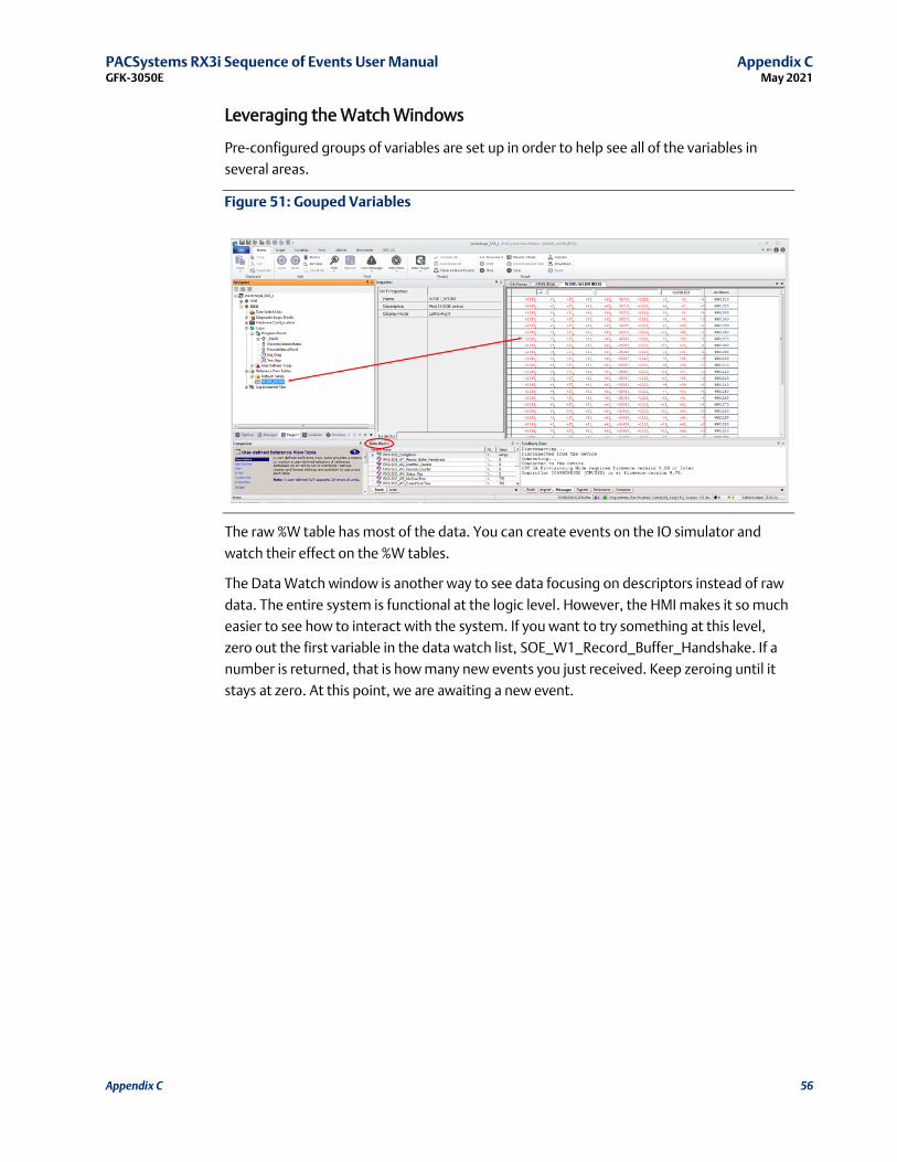
PACSystems RX3i Sequence of Events User Manual Appendix C GFK-3050E May 2021
Appendix C 56
Leveraging the Watch Windows
Pre-configured groups of variables are set up in order to help see all of the variables in
several areas.
Figure 51: Gouped Variables
The raw %W table has most of the data. You can create events on the IO simulator and
watch their effect on the %W tables.
The Data Watch window is another way to see data focusing on descriptors instead of raw
data. The entire system is functional at the logic level. However, the HMI makes it so much
easier to see how to interact with the system. If you want to try something at this level,
zero out the first variable in the data watch list, SOE_W1_Record_Buffer_Handshake. If a
number is returned, that is how many new events you just received. Keep zeroing until it
stays at zero. At this point, we are awaiting a new event.

PACSystems RX3i Sequence of Events User Manual Appendix C GFK-3050E May 2021
Appendix C 57
C.3 HMI Target
This section is on how to utilize a local HMI to visualize and log the SOE data on a local
storage media. This allows for a robust long term and low-cost logging solution.
One of the advantages of using the Quickpanel+ application is it can run in Simulation
Mode on a PC. Before running in Simulation Mode, verify that the application is fully
functional by turning the Enable IO parameter to True. We can then Download and Start
the Quickpanel+ application on the PC.
To run the target in simulation mode:
1. Select the target and turn the Enable I/O to True in the inspector pane.
2. Download and Run the Quickpanel+ application.
3. ThenDownload and Start the Quickpanel+ application on the PC.
Figure 52: Enable I/O Parameter Set to True

PACSystems RX3i Sequence of Events User Manual Appendix C GFK-3050E May 2021
Appendix C 58
QuickPanel+ Application (HMI)
The QuickPanel+ application simulates runtime values of the system. The user can review
components statuses of the system in real time.
The following definitions describe the key features of the demo application and how to
interact with the HMI.
Figure 53: Demonstration Application
1. Scan Times: this item displays minimum, current, and maximum PLC scan times
converted to mS for display. These are words (5), (7), and (9) of the SoE User
Memory Map.
2. LAN2 Status: monitors which ports are connected to other devices using LAN2
Profinet Status Bits on the CPU.
3. PROFINET Device #1 Status: monitors the PNS OK status bit. Green indicates the
module is functioning properly, and red indicates the module is powering up or
has failed.
4. PNS Device #1 Status: monitors which port is connected and whether or not it’s
communicating using the PNS101 status bits.
5. IRIG-B Status: this reflects the PNS Synchronized to the GPS global time status bit
6. Digital Inputs Status: monitors the status of inputs 1 through 4 on the MDL
module.
7. PLC Restart Flag: indicates if a power cycle occurred. Helpful in pointing to a
possible loss of data. Obtained by reading SoE Status (word 4) bit 2 of the SoE User
Memory Map.
8. PLC Restart Reset: writing zero to the PLC Restart flag (SoE Status Bit 2 of the SoE
User Memory Map).
9. Go to SoE Records Table
10. Record Count: shows the number of events that are available in the SoE Records
Buffer. This is obtained by reading the SoE Record Communication Buffer
Handshake word (first word of the SoE User Memory Map).
PACSystems RX3i Sequence of Events User Manual Appendix C GFK-3050E May 2021
Appendix C 59
11. Overflow Count: indicates the number of times the internal buffer overflowed.
This is obtained by reading the second word of the SoE User Memory Map.
12. PNS Overflow Count: indicates the internal events buffer has overflowed.
Obtained by reading SoE Status word (4) Bit 1 of the SoE User Memory Map.
13. PNS 75% Full: obtained by reading SoE Status word (4) bit 5 of the SoE User
Memory Map.
14. PNS 50% Full: obtained by reading SoE Status word (4) bit 4 of the SoE User
Memory Map.
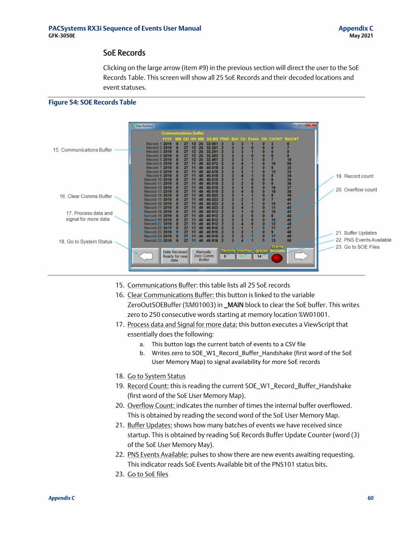
PACSystems RX3i Sequence of Events User Manual Appendix C GFK-3050E May 2021
Appendix C 60
SoE Records
Clicking on the large arrow (item #9) in the previous section will direct the user to the SoE
Records Table. This screen will show all 25 SoE Records and their decoded locations and
event statuses.
Figure 54: SOE Records Table
15. Communications Buffer: this table lists all 25 SoE records
16. Clear Communications Buffer: this button is linked to the variable
ZeroOutSOEBuffer (%M01003) in _MAIN block to clear the SoE buffer. This writes
zero to 250 consecutive words starting at memory location %W01001.
17. Process data and Signal for more data: this button executes a ViewScript that
essentially does the following:
a. This button logs the current batch of events to a CSV file
b. Writes zero to SOE_W1_Record_Buffer_Handshake (first word of the SoE
User Memory Map) to signal availability for more SoE records
18. Go to System Status
19. Record Count: this is reading the current SOE_W1_Record_Buffer_Handshake
(first word of the SoE User Memory Map).
20. Overflow Count: indicates the number of times the internal buffer overflowed.
This is obtained by reading the second word of the SoE User Memory Map.
21. Buffer Updates: shows how many batches of events we have received since
startup. This is obtained by reading SoE Records Buffer Update Counter (word (3)
of the SoE User Memory May).
22. PNS Events Available: pulses to show there are new events awaiting requesting.
This indicator reads SoE Events Available bit of the PNS101 status bits.
23. Go to SoE files
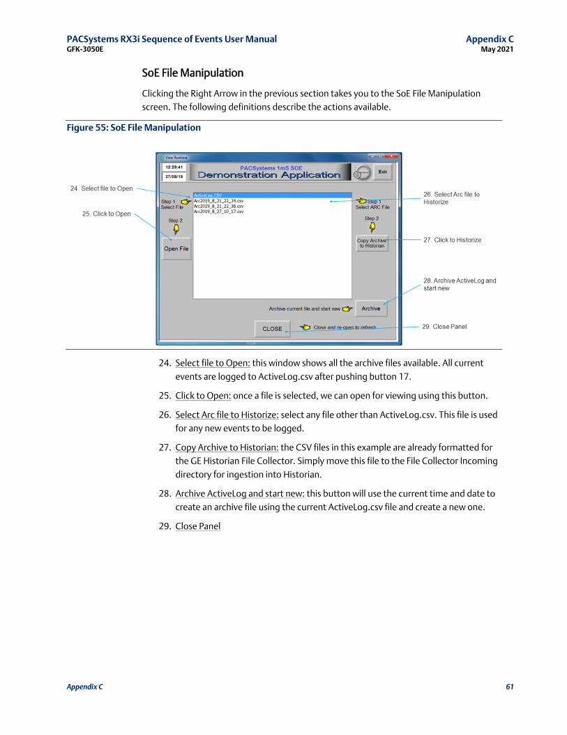
PACSystems RX3i Sequence of Events User Manual Appendix C GFK-3050E May 2021
Appendix C 61
SoE File Manipulation
Clicking the Right Arrow in the previous section takes you to the SoE File Manipulation
screen. The following definitions describe the actions available.
Figure 55: SoE File Manipulation
24. Select file to Open: this window shows all the archive files available. All current
events are logged to ActiveLog.csv after pushing button 17.
25. Click to Open: once a file is selected, we can open for viewing using this button.
26. Select Arc file to Historize: select any file other than ActiveLog.csv. This file is used
for any new events to be logged.
27. Copy Archive to Historian: the CSV files in this example are already formatted for
the GE Historian File Collector. Simply move this file to the File Collector Incoming
directory for ingestion into Historian.
28. Archive ActiveLog and start new: this button will use the current time and date to
create an archive file using the current ActiveLog.csv file and create a new one.
29. Close Panel
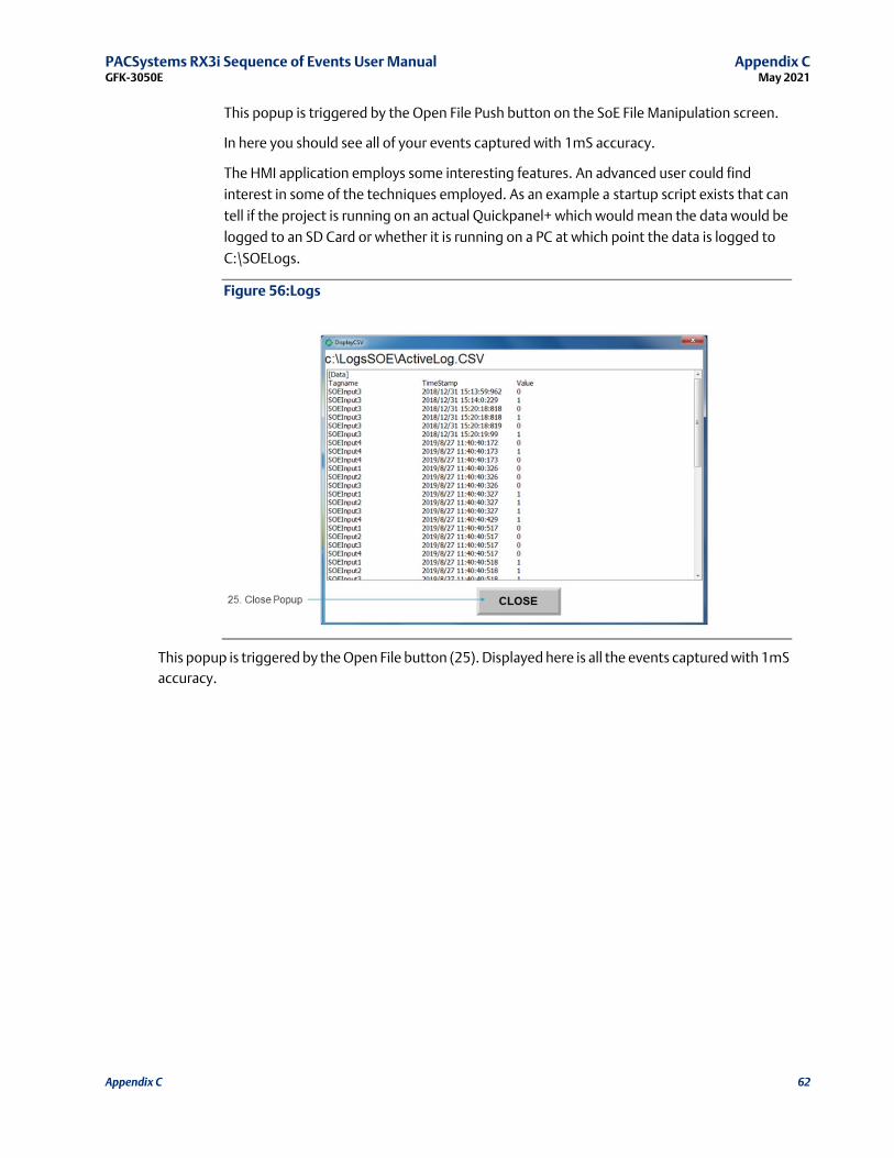
PACSystems RX3i Sequence of Events User Manual Appendix C GFK-3050E May 2021
Appendix C 62
This popup is triggered by the Open File Push button on the SoE File Manipulation screen.
In here you should see all of your events captured with 1mS accuracy.
The HMI application employs some interesting features. An advanced user could find
interest in some of the techniques employed. As an example a startup script exists that can
tell if the project is running on an actual Quickpanel+ which would mean the data would be
logged to an SD Card or whether it is running on a PC at which point the data is logged to
C:\SOELogs.
Figure 56:Logs
This popup is triggered by the Open File button (25). Displayed here is all the events captured with 1mS
accuracy.

General Contact Information
Home link: http://www.emerson.com/industrial-automation-controls
Knowledge Base: https://www.emerson.com/industrial-automation-controls/support
Technical Support
Americas Phone: 1-888-565-4155 1-434-214-8532 (If toll free option is unavailable)
Customer Care (Quotes/Orders/Returns): [email protected] Technical Support: [email protected]
Europe Phone: +800-4444-8001 +420-225-379-328 (If toll free option is unavailable)
+39-0362-228-5555 (from Italy - if toll-free 800 option is unavailable or dialing from a mobile telephone)
Customer Care (Quotes/Orders/Returns): [email protected] Technical Support: [email protected]
Asia Phone: +86-400-842-8599 +65-6955-9413 (All other Countries)
Customer Care (Quotes/Orders/Returns): [email protected] Technical Support: [email protected]
Any escalation request should be sent to [email protected]
Note: If the product is purchased through an Authorized Channel Partner, please contactthe seller directly for any support.
Emerson reserves the right to modify or improve the designs or specifications of the products mentioned in this manual at
any time without notice. Emerson does not assume responsibility for the selection, use, or maintenance of any product.
Responsibility for proper selection, use, and maintenance of any Emerson product remains solely with the purchaser.
© 2021 Emerson. All rights reserved.
Emerson Terms and Conditions of Sale are available upon request. The Emerson logo is a trademark and service mark of Emerson Electric Co. All other marks are the property of their respective owners.