Embed Size (px)
Citation preview

Customer Order Number: DOC-784560=
Documentation Part Number:Packet OC-3 Interface Processor(POSIP-OC3-50)Installation and Configuration
78-4560-03
Product Numbers: POSIP-OC3-50-SM(=) and POSIP-OC3-50-MM(=)
This publication contains instructions for installing and configuring the Packet OC-3 InterfaceProcessor (POSIP-OC3-50), which is a fixed-configuration interface processor that usessecond-generation Versatile Interface Processor (VIP2-50) technology. The POSIP-OC3-50complies with the Packet-Over-SONET specification.
This publication contains basic configuration steps and examples and includes the procedures forreplacing memory on the POSIP-OC3-50. The POSIP-OC3-50 is compatible with any Cisco 7500series routers. For the POSIP-OC3-50 to operate properly in the Cisco 7000 series routers, the 7000Series Route Switch Processor (RSP7000) and 7000 Series Chassis Interface (RSP7000CI)mustbeinstalled.
Note For specific POSIP-OC3-50 hardware and software prerequisites, refer to the sections“POSIP-OC3-50 Hardware Requirements,” on page 11, and “POSIP-OC3-50 SoftwareRequirements” on page 12.
The entire POSIP-OC3-50 assembly is a field replaceable unit (FRU); the dual-width port adapterinstalled on POSIP-OC3-50 isnot an FRU.
Document ContentsSections in this publication include the following:
• If You Need More Information on page 2
• Packet-Over-SONET Terms and Acronyms on page 3
• Packet-Over-SONET Overview on page 3
• Packet-Over-SONET and PPP Reference Material on page 4
• What Is the POSIP-OC3-50? on page 4
• POSIP-OC3-50 Specifications and Guidelines on page 7
1Cisco Systems, Inc.All rights reserved.
170 West Tasman DriveSan Jose, CA 95134-1706USA
Cisco Systems, Inc.Corporate Headquarters
Copyright © 1997–1998

If You Need More Information
• POSIP-OC3-50 Installation Prerequisites on page 11
• POSIP-OC3-50 Installation Procedures on page 24
• Configuring the POSIP-OC3-50 on page 30
• Replacing POSIP-OC3-50 SDRAM and SRAM on page 40
• Cisco Connection Online on page 48
If You Need More InformationThe Cisco IOS software running your router contains extensive features and functionality. Forinformation on Cisco IOS software and for general installation and maintenance information foryour router, use the following resources:
• Cisco Documentation CD-ROM package
Cisco documentation and additional literature are available in a CD-ROM package, which shipswith your product. The Documentation CD-ROM, a member of the Cisco Connection Family, isupdated monthly; therefore, it might be more up to date than printed documentation. To orderadditional copies of the Documentation CD-ROM, contact your local sales representative or callcustomer service. The CD-ROM package is available as a single package or as an annualsubscription.
• For Cisco IOS software configuration information and support, refer to the modularconfiguration and modular command reference publications in the Cisco IOS softwareconfiguration documentation set that corresponds to the software installed on your Ciscohardware. You can also refer to the Cisco IOS software release notes for the version of softwareyou are using on your hardware.
• For hardware installation and maintenance information on the Cisco 7500 series routers, refer totheCisco 7500 Series Installation and Configuration Guide that shipped with your Cisco 7500series router.
• For hardware installation and maintenance information on the Cisco 7000 series routers, refer totheCisco 7000 Hardware Installation and Maintenancemanual and theCisco 7000 User Guide,or to theCisco 7010 Hardware Installation and Maintenance manual and theCisco 7010 UserGuide, which shipped with your Cisco 7000 or Cisco 7010 router, respectively.
Note You can access Cisco IOS software documentation and hardware installation andmaintenance documentation on the World Wide Web at http://www.cisco.com,http://www-china.cisco.com, http://www-europe.cisco.com.
If you are reading Cisco documentation on the World Wide Web, you can submit commentselectronically. ClickFeedbackon the toolbar, and then selectDocumentation. After you completethe form, clickSubmit to send it to Cisco. We appreciate your comments.
• To view Cisco documentation or obtain general information about documentation, refer to thefollowing sources:
— Documentation CD-ROM.
— Cisco Connection Online (CCO). (Refer to the section “Cisco Connection Online,” onpage 48.)
2 Packet OC-3 Interface Processor (POSIP-OC3-50) Installation and Configuration

Packet-Over-SONET Terms and Acronyms
— Customer Service at 800 553-6387 or 408 526-7208. Customer Service hours are 5:00 a.m.to 6:00 p.m. Pacific time, Monday through Friday (excluding company holidays). You canalso send e-mail to [email protected].
— TheCisco Information Packet that shipped with your router.
Packet-Over-SONET Terms and AcronymsThe following are common Packet-over-SONET terms and acronyms for your reference:
• ITU-T—International Telecommunications Union Telecommunication Sector (formerly theConsultative Committee for International Telegraph and Telephone [CCITT]).
• MIB—Management Information Base.
• PPP—Point-to-Point Protocol, which provides a standard encapsulation method for transportingmultiprotocol datagrams over point-to-point links.
• SDH—Synchronous Digital Hierarchy. International standard for optical digital transmission athierarchical rates from 155.520 Mbps (STM-1) to 2.5 gigabits per second (Gbps) (STM-16) andgreater.
• SONET—Synchronous Optical Network. An American National Standards Institute (ANSI)standard (T1.1051988) for optical digital transmission at hierarchical rates from 51.840 Mbps(STS-1) to 2.5 Gbps (STS-48) and greater.
• OC-3—Optical Carrier-3 specification for SONET STS-3c and SDH STM-1 transmission rates.
• SPE—Synchronous Payload Envelope; the payload portion of the SONET frame into which theoctet-oriented user date is mapped. Octet boundaries are aligned with the SPE octet boundaries.
Packet-Over-SONET OverviewThe Packet-Over-SONET specification is primarily concerned with the use of the PPP encapsulationover SONET/SDH links. Since SONET/SDH is by definition a point-to-point circuit, PPP is wellsuited for use over these links. Point-to-Point Protocol (PPP) was designed as a standard method ofcommunicating over point- to-point links.
The Synchronous Optical Network (SONET) is an octet-synchronous multiplex scheme that definesa family of standard rates and formats. The basic rate for Packet-Over-SONET is that ofSTS-3c/STM-1, which is 155.520 Mbps. The available information bandwidth is 149.760 Mbps,which is the STS-3c/STM-1 SPE with section, line, and path overhead removed.
The ITU-T defines a series of SDH transmission rates beginning at 155.520 Mbps, as follows:
SONET1
1. ANSI-defined SONET specifications.
SDH equivalent
STS-3c2
2. Currently supported by the POSIP-OC3-50.
STM-12
STS-12c STM-4c
STS-48c STM-16c
Packet OC-3 Interface Processor (POSIP-OC3-50) Installation and Configuration 3

Packet-Over-SONET and PPP Reference Material
Despite the name, SONET is not limited to optical links. Electrical specifications have been definedfor single-mode fiber, multimode fiber, and CATV 75-ohm coaxial cable; however, thePOSIP-OC3-50 currently allows only transmission over single-mode and multimode optical fiber,and transmission rates are integral multiples of 51.840 megabits per second (Mbps), which can beused to carry T3/E3 bit-synchronous signals.
The following transmission multiples are currently specified and commonly used:
• STS-1—51.840 Mbps
• STS-3c—155.520 Mbps (the POSIP-OC3-50 conforms to STS-3c)
• STS-12c—622.080 Mbps
• STS-48c—2,488.320 Mbps
Packet-Over-SONET and PPP Reference MaterialThe following references discuss concepts and specifications of Packet-Over-SONET and PPP:
• Simpson, W., Editor, “The Point-to-Point Protocol (PPP),” RFC 1548, Daydreamer, December1993.
• Simpson, W., Editor, “PPP in HDLC Framing,” RFC 1662, Daydreamer, July 1994.
• Simpson, W, Editor, “PPP Over SONET/SDH,” RFC1619, May 1995.
• “American National Standard for Telecommunications - Digital Hierarchy - Optical InterfaceRates and Formats Specification,” ANSI T1.105-1991.
• “American National Standard for Telecommunications - Synchronous Optical Network(SONET) Payload Mappings,” ANSI T1.105.02-1993 draft.
• CCITT Recommendation G.707, “Synchronous Digital Hierarchy Bit Rates,” June 1992.
What Is the POSIP-OC3-50?The POSIP-OC3-50 (see Figure 1 and Figure 2) provides a single 155.520-Mbps, Packet OC-3network interface for Cisco 7000 series and 7500 series routers.
Figure 1 POSIP-OC3-50 (Faceplate View, Horizontal Orientation)
ENABLED
155-
MMRX C
ARRIER
RX PACKETS PACKET OVER SONET/SDH
H64
67
4 Packet OC-3 Interface Processor (POSIP-OC3-50) Installation and Configuration

What Is the POSIP-OC3-50?
oard.alled,h port (FRU).
idthus inhe
Figure 2 Packet-Over-SONET Interface Processor (POSIP-OC3-50)
Caution The POSIP-OC3-50 is made up of two main parts: a dual-width port adapter and a motherbTo prevent problems with the POSIP-OC3-50 and with the system in which the POSIP-OC3-50 is instdo not attempt to separate the port adapter from its motherboard or to install other single- or dual-widtadapters on the POSIP motherboard. The entire POSIP-OC3-50 assembly is a field replaceable unit
Network interfaces reside on the POSIP-OC3-50 and provide a direct connection between thehigh-speed Cisco Extended Bus (CxBus or CyBus) and the external networks. The physical layerinterface is OC-3.
The POSIP-OC3-50 uses an R5000 central processing unit (CPU), running at 200 Mhz, and comesconfigured with 32 MB of synchronous dynamic random-access memory (SDRAM) and 4 MB ofstatic random-access memory (SRAM) as the factory default memory configuration. The SDRAMand SRAM on the POSIP-OC3-50 models can be upgraded as your system configuration requiresand SRAM and SDRAM memory upgrade options are made available by Cisco Systems. (ForSDRAM and SRAM replacement procedures, refer to the section “Replacing POSIP-OC3-50SDRAM and SRAM” on page 40.)
Caution Traffic from multiple POSIP-OC3-50 network interfaces could theoretically exceed the bandwof the CxBus or CyBus. This would cause packets to be dropped; therefore, a practical limit for the CxBCisco 7000 series chassis is two POSIP-OC3-50s, and for the CyBus in Cisco 7500 series chassis, tpractical limit is four POSIP-OC3-50s.
Packet data is transported using Point-to-Point Protocol (PPP) and is mapped into theSTS-3c/STM-1 frame. The encapsulations used add approximately half of the number of bytes oftransport overhead as that involved with ATM using ATM Adaptation Layer 5 (AAL5) and line cardcontrol (LCC) Subnetwork Access Protocol (SNAP) encapsulations.
The OC-3 interface is compliant with RFC 1619, “PPP over SONET/SDH,” and RFC 1662, “PPP inHDLC-like Framing.” The POSIP-OC3-50 supports RFC 1619 Point-to-Point Protocol overSONET/SDH encapsulation, and provides support for SNMP agent v1 (RFC 1155-1157), and MIBII (RFC 1213). The POSIP-OC3-50 supports the following features:
H10
458
CPUBus connector
SRAM daughter
card SDRAM DIMM
Boot ROM
ENABLED
RX CARRIE
RRX P
ACKETS
155-MM
PACKET OVER SONET/SDH
Packet OC-3 Interface Processor (POSIP-OC3-50) Installation and Configuration 5

What Is the POSIP-OC3-50?
• Standards-compliant SONET/SDH interface; SONET/STS-3c and SDH/STM-1 framing andsignaling overhead
• Full-duplex operation at 155 Mbps
• Intermediate reach optical interface with single-mode fiber
• Optical interface with multimode fiber
• Online insertion and removal, enabling you to remove, add, or replace POSIP-OC3-50s on line
• Microcode is loaded into and operates from synchronous dynamic random-access memory(SDRAM)
• An R5000 central processing unit (CPU), running at 200 Mhz
• Support for 16-bit and 32-bit cyclic redundancy checking (CRC-16 and CRC-32, respectively)
Note Only CRC-16 can be used if the SONET payload scrambling feature is enabled. (For specificand important hardware and software requirements, refer to the section “POSIP-OC3-50 InstallationPrerequisites,” on page 11, and to use the SONET payload scrambling feature, refer to the section“Configuring SONET Payload Scrambling” on page 33.)
POSIP-OC3-50 Memory ConfigurationsFollowing are the POSIP-OC3-50 SDRAM and SRAM configurations by product number:
• POSIP-OC3-50-SM(=)—4 MB of SRAM, 32 MB of SDRAM (with single-mode optical-fiberconnections)
• POSIP-OC3-50-MM(=)—4 MB of SRAM, 32 MB of SDRAM (with multimode optical-fiberconnections)
The following additional SDRAM and SRAM upgrade products are available:
• MEM-VIP250-8M-S=—8 MB of SRAM
• MEM-VIP250-64M-D=—64 MB of SDRAM
• MEM-VIP250-128M-D=—128 MB of SDRAM
You can use any combination of available SDRAM and SRAM configurations on thePOSIP-OC3-50.
POSIP-OC3-50 Network Management SupportFollowing is the protocol and management information base (MIB) support for the POSIP-OC3-50:
• SNMP agent v1 (RFC 1155-1157)
• MIB II (RFC 1213); POSIP MIB support will not be available with the initial POSIP-OC3-50release.
Encapsulation Method Supported for POSIP-OC3-50The following encapsulation method is supported by the POSIP-OC3-50: RFC 1619 Point-to-PointProtocol over SONET/SDH.
6 Packet OC-3 Interface Processor (POSIP-OC3-50) Installation and Configuration

POSIP-OC3-50 Specifications and Guidelines
POSIP-OC3-50 Specifications and GuidelinesThe Packet OC-3 interface is full duplex. You must use the appropriate optical-fiber interfacecable(s) to connect the POSIP-OC3-50 with an external network. Refer to the section“POSIP-OC3-50 Interface Cables,” on page 12, for descriptions of connectors and optical-fibercables. The POSIP-OC3-50, shown in Figure 2, provides an interface to switching fabrics fortransmitting and receiving data at rates of up to 155.520 Mbps bidirectionally. The POSIP-OC3-50connects to the following physical layers:
• Multimode—155 Mbps, OC-3 optical fiber (SONET STS-3c or SDH STM-1)
• Single-mode—155 Mbps, OC-3 optical fiber (SONET STS-3c or SDH STM-1)
POSIP-OC3-50 MicrocodeThe POSIP-OC3-50 microcode is a software image that provides card-specific software instructions.Cisco 7000 series and Cisco 7500 series routers support downloadable microcode, which enablesyou to upgrade microcode versions by downloading new microcode images, storing them in Flashmemory, and instructing the system to load an image from Flash memory. You can store multipleimages for an interface type and instruct the system to load any one of them with a configurationcommand. All interfaces of the same type (all POSIP-OC3-50s, and so on) will load the samemicrocode image from a single image stored in Flash memory. The Flash-based boot read-onlymemory (ROM) device on the POSIP-OC3-50 contains a microcode boot image that instructs thesystem to load the full microcode image as described by the configuration.
Although multiple microcode versions for a specific interface type can be stored concurrently inFlash memory, only one image can load at startup. Theshow controller cbuscommand displays thecurrently loaded and running microcode version for each interface processor. Theshow microcodecommand displays the microcode images bundled with the Cisco IOS software.
An example of theshow microcode command follows:
Router# sh microcodeMicrocode bundled in system
Card Microcode Target Hardware DescriptionType Version Version---- --------- --------------- -----------VIP2 21.40 2.x VIP2 version 21.40
(additional display text omitted from this example)
In the preceding example, the POSIP-OC3-50’s microcode is listed asVIP2 because the POS portadapter is attached to a VIP2 motherboard and uses its microcode image. For a complete descriptionof microcode and downloading procedures, refer to the section “Upgrading Microcode” on page 37.
Packet-Over-SONET Distance LimitationsThe Packet-Over-SONET specification for optical-fiber transmission defines two types of fiber:single mode and multimode. Modes can be thought of as bundles of light rays entering the fiber at aparticular angle. Single-mode fiber allows only one mode of light to propagate through the fiber,while multimode fiber allows multiple modes of light to propagate through the fiber.
Multiple modes of light propagating through the fiber travel different distances depending on theentry angles, which causes them to arrive at the destination at different times (a phenomenon calledmodal dispersion); therefore, single-mode fiber is capable of higher bandwidth and greater cable rundistances than multimode fiber.
Packet OC-3 Interface Processor (POSIP-OC3-50) Installation and Configuration 7

Evaluating Power Budget
Table 1 lists typical maximum distances for single-mode and multimode transmission.
Note If the distance between two connected stations is greater than the maximum distances listed,significant signal loss can result, making transmission unreliable.
Table 1 Maximum Optical-Fiber Power Budget and Transmission Distances
Evaluating Power BudgetTo design an efficient optical data link, you should evaluate the power budget. The power budget isthe amount of light available to overcome attenuation in the optical link and to exceed the minimumpower that the receiver requires to operate within its specifications. Proper operation of an opticaldata link depends on modulated light reaching the receiver with enough power to be correctlydemodulated. Attenuation, caused by the passive media components (cables, cable splices, andconnectors), is common to both multimode and single-mode transmission.
The following variables reduce the power of the signal (light) transmitted to the receiver inmultimode transmission:
• Chromatic dispersion (spreading of the signal in time because of the different speeds of lightwavelengths)
• Modal dispersion (spreading of the signal in time because of the different propagation modes inthe fiber)
Attenuation is significantly lower for optical fiber than for other media. For multimode transmission,chromatic and modal dispersion reduce the available power of the system by the combineddispersion penalty (dB). The power lost over the data link is the sum of the component, dispersion,and modal losses.
Table 2 lists the factors of attenuation and dispersion limits for typical optical-fiber cable.
Table 2 Typical Optical-Fiber Link Attenuation and Dispersion Limits
TransceiverType
PowerBudget Transmit Power Receive Power
Maximum Distancebetween Stations 1
1. Table 1 gives typical results. You should use the power budget calculations to determine the actual distances.
Single-mode2
2. Complies with Bellcore GR-253 Intermediate Reach Specification.
16 dB –15 to –8 dBm,at 1270–1380 nm
–31 to –8 dBm Up to 9 miles (15 kilometers)
Multimode2 11.5 dB –18.5 to –14 dBm,at 1270–1380 nm
–30 to –14 dBm Up to 1.5 miles (3 kilometers)
Limits Single Mode Multimode
Attenuation 0.5 dB 1.0 dB/km
Dispersion No limit 500 MHz(km)1
1. The product of bandwidth and distance must be less than500 MHz (km).
8 Packet OC-3 Interface Processor (POSIP-OC3-50) Installation and Configuration

Approximating the Multimode Power Margin
Approximating the Multimode Power MarginThe LED used for a multimode transmission light source creates multiple propagation paths of light,each with a different path length and time requirement to cross the optical fiber, causing signaldispersion (smear). Higher order mode loss (HOL) results from light from the LED entering the fiberand being radiated into the fiber cladding. A worst case estimate of power margin (PM) formultimode transmissions assumes minimum transmitter power (PT), maximum link loss (LL), andminimum receiver sensitivity (PR). The worst case analysis provides a margin of error, although notall of the parts of an actual system will operate at the worst case levels.
The signal must meet the worst case optical power parameters listed in Table 3.
Table 3 POSIP Optical Power Requirements
The power budget (PB) is the maximum possible amount of power transmitted. The followingequation shows the calculation of the power budget for multimode, worst case:
PB = PT – PR
PB = –18.5 – (–30)
PB = –18.5 + 30
PB = 11.5 dB
The power margin (PM) calculation is derived from the power budget minus the link loss (LL), asfollows:
PM = PB – LL
If the power margin is positive, as a rule, the link will work.
Table 4 lists the factors that contribute to link loss and the estimate of the link loss value attributableto those factors.
Table 4 Estimating Link Loss
After calculating the power budget minus the data link loss, the result should be greater than zero;this is the power margin. Results less than zero may have insufficient power to operate the receiver.
PowerParameters Single-Mode Multimode
PT –15 dBm –18.5 dBm
PR –31 dBm –30 dBm
PM 16 dB 11.5 dB
Link Loss Factor Estimate of Link Loss Value
Higher order mode losses 0.5 dB
Clock recovery module 1 dB
Modal and chromatic dispersion Dependent on fiber and wavelength used
Connector 0.5 dB
Splice 0.5 dB
Fiber attenuation 1 dB/km
Packet OC-3 Interface Processor (POSIP-OC3-50) Installation and Configuration 9

Evaluating Power Budget
Multimode Power Margin Example with Sufficient Power for TransmissionThe following is an example of a multimode power margin (PM) calculation based on the followingvariables:
• Length of multimode link = 3 kilometers (km), with a loss of 1.0 dB per km
• 4 connectors, each with a loss of 0.5 dB
• 3 splices, each with a loss of 0.5 dB
• Higher order loss (HOL) of 0.5 dB
• Clock recovery module (CRM), with a loss of 1.0 dB
Estimate the power margin as follows:
PM = PB – LL
PM = 11.5 dB – 3 km (1.0 dB/km) – 4 (0.5 dB) – 3 (0.5 dB) – 0.5 dB (HOL) – 1 dB (CRM)
PM = 11.5 dB – 3 dB – 2 dB – 1.5 dB – 0.5 dB – 1 dB
PM = 3.5 dB
The positive value 3.5 dB indicates that this link would have sufficient power for transmission.
Single-Mode and Multimode Transmit and Receive Power SpecificationsThe single-mode signal source is an injection laser diode. The multimode signal source is alight-emitting diode (LED). Single-mode transmission is useful for longer distances because thereis a single transmission path within the fiber, and dispersion does not occur. In addition, chromaticdispersion is also reduced because laser light is essentially monochromatic. Power specifications forsingle-mode transmission follow:
• Transmit (TX) power: –15 to –8 dBm @ wavelength 1260–1360 nanometers (nm)
• Receive (RX) power: –31 to –8 dBm
Power specifications for multimode transmission follow:
• TX power: –18.5 to –14 dBm @ wavelength 1270–1380 nm
• RX power: –30 to –14 dBm
Single-Mode Power Budget ExampleYou can calculate the single-mode power budget using the equation PB = PM – LL. The followingexample of a single-mode power budget is based on two buildings, 11 kilometers apart (with a lossof 0.05 dB/km), connected through a patch panel in an intervening building with a total of 12connectors (each with a loss of 0.5 dB). Use the single-mode power margin (PM) value of 16db fromTable 3. Estimate the single-mode power budget as follows:
PB = PM – LL
PB = 16 dB – 11 km (0.5 dB/km) – 12 (0.5 dB)
PB = 16 dB – 5.5 dB – 6 dB
PB = 5.5 dB
The value of 5.5 dB indicates that this link would have sufficient power for transmission and is notin excess of the maximum receiver input power.
10 Packet OC-3 Interface Processor (POSIP-OC3-50) Installation and Configuration

Using Statistics to Estimate the Power Budget
Using Statistics to Estimate the Power BudgetStatistical models more accurately determine the power budget than the worst case method.Determining the link loss with statistical methods requires accurate knowledge of variations in thedata link components. Statistical power budget analysis is beyond the scope of this document. Forfurther information, refer to ITU-T standards and your equipment specifications.
Additional Power Budget and Attenuation ReferencesThe following publications contain information on determining attenuation and power budget:
• T1E1.2/92-020R2 ANSI, the Draft American National Standard for Telecommunicationsentitled “Broadband ISDN Customer Installation Interfaces: Physical Layer Specification.”
• Power Margin Analysis, AT&T Technical Note,TN89-004LWP, May 1989
POSIP-OC3-50 Installation PrerequisitesBefore you begin this installation, review the safety and ESD-prevention guidelines in this sectionto avoid injuring yourself or damaging the equipment. This section also provides a list of parts andtools you will need to perform the installation.
POSIP-OC3-50 Hardware RequirementsThe POSIP-OC3-50 will operate in the Cisco 7000 series routers providing these routers have the7000 Series Route Switch Processor (RSP7000) and 7000 Series Chassis Interface (RSP7000CI)installed. The POSIP-OC3-50 will not operate with the Route Processor (RP) and Switch Processor(SP) or Silicon Switch Processor [SSP]) in older Cisco 7000 series models.
The POSIP-OC3-50 will operate in all of the Cisco 7500 series routers, which use the Route SwitchProcessor (RSP1, RSP2, or RSP4).
Note The POSIP-OC3-50 has firmware that allows it to do SONET payload scrambling; however,this functionality might disallow support for 32-bit cyclic redundancy check (CRC-32) dependingon the hardware version of the dual-width POS port adapter you have installed.
Use the Table X to determine CRC and SONET payload scrambling compatibility for the dual-widthPOS port adapter currently installed in your system. While the POSIP-OC3-50 supports CRC-32and CRC-16, you can only use CRC-16 if you have a dual-width POS port adapter that is HardwareVersion 1.5, 1.30, or 1.31.
Table 5 Dual-Width POS Port Adapter Hardware Version Compatibility Matrix
CRC-16 CRC-32 SONET Payload Scrambling Hardware Version Required
Yes Yes No Version 1.4, Version 1.14 (decimal)Version 1.4, Version 1.E (hexadecimal)
Yes No Yes Version 1.5, Version 1.30, Version 1.31 (decimal)
Version 1.5, Version 1.1E, Version 1.1F (hexadecimal)
– – – Version 1.0 to Version 1.3 (beta hardware)
Packet OC-3 Interface Processor (POSIP-OC3-50) Installation and Configuration 11

POSIP-OC3-50 Installation Prerequisites
POSIP-OC3-50 Software RequirementsThe POSIP-OC3-50 is compatible with any Cisco 7500 series or Cisco 7000 series router runningCisco IOS Release 11.1(14)CA or later.
The SONET payload scrambling feature is supported by the POSIP-OC3-50 in any Cisco 7500series or Cisco 7000 series router running Cisco IOS Release 11.1(15)CA or later.
Use theshow diagbusslot command to view specific hardware information for a POSIP-OC3-50installed in your system.
Use theshow version command to display the current hardware configuration of the router,including the system software version that is currently loaded and running, and the type of systemprocessor board installed: RSP, RSP7000, and so forth. Use theshow controller cbuscommand tolist all installed interfaces and to show the currently loaded and running microcode version for each.You can check the version of the default ROM image by either removing the board and checking theROM labels, or by configuring the interface or system software to boot from ROM, restarting thesystem, and using these same commands to check the running version.
Use theshow version command to display the current system software version, and use theshow controller cbuscommand to display the microcode version of the system processor and eachinterface processor.
If the running system software is an earlier version than those listed above, check Flash memory todetermine if the required images are available on your system. Use theshow flash command todisplay a list of all files stored in Flash memory. There are two types of Flash memory:PCMCIA-based Flash memory cards, referred to as either slot0: or slot1:, and bootflash, which isimbedded Flash memory on the POSIP-OC3-50. Specific microcode images can be loadedautomatically from the Cisco IOS bundle, or specifically from Flash memory.
Note We recommend you use the Cisco IOS-bundled POSIP-OC3-50 microcode image for systemcompatibility.
POSIP-OC3-50 Interface CablesUse single-mode or multimode, optical-fiber interface cable to connect your router to a network orto connect two OC3-equipped routers back-to-back.
Cables can be obtained from the following cable vendors:
• AT&T
• Siemens
• Red-Hawk
• Anixter
• AMP
Note Single-mode and multimode optical-fiber cables for the POSIP-OC3-50 are not availablefrom Cisco Systems, but are available from commercial cable vendors.
For SONET/SDH single-mode and multimode optical-fiber connections, use one duplex SC-typecable (see Figure 3) or two simplex SC-type cables (see Figure 4).
12 Packet OC-3 Interface Processor (POSIP-OC3-50) Installation and Configuration

Guidelines for Installing and Removing Processor Modules
e thatuse thege the
Tod, doC3-50
Figure 3 Duplex SC Cable Connector
Figure 4 Simplex SC Cable Connector
Guidelines for Installing and Removing Processor ModulesThe processor modules for the Cisco 7000 series and Cisco 7500 series slide into slots in the rear ofthe chassis and connect directly to the backplane. The backplane slots are keyed so that the processormodules can be installed only in the slots designated for them. Figure 5 shows the ejector levers andcaptive installation screws on a typical interface processor. To remove an interface processor, loosenthe captive screws and pull the ejector levers to the sides; then pull the module out using the handle.
To insert an interface processor, reverse the process, making sure to firmly seat the interfaceprocessor in its connectors on the backplane. For detailed directions, refer to the procedures in“Removing a POSIP-OC3-50,” on page 25, and “Installing a New or Replacement POSIP-OC3-50and Connecting Interface Cables” on page 26.
Caution Always use the ejector levers to remove or install the POSIP-OC3-50. The ejectors help ensurbackplane connectors on the card are fully seated in, or fully ejected from, the backplane. Failure to ejector levers could result in a partial backplane connection, which can hang the system or could damabackplane.
Note The POSIP-OC3-50 is oriented horizontally in the Cisco 7010 and Cisco 7505 and verticallyin the Cisco 7000, Cisco 7507, and Cisco 7513. There are no restrictions on slot locations orsequence; you can install a POSIP-OC3-50 in any available interface processor slot.
Caution The POSIP-OC3-50 is made up of two parts: a dual-width port adapter and a motherboard.prevent problems with the POSIP-OC3-50 and with the system in which the POSIP-OC3-50 is installenot attempt to separate the POSIP-OC3-50’s port adapter from its motherboard. The entire POSIP-Oassembly is a field replaceable unit (FRU).
H22
14
H23
99
Packet OC-3 Interface Processor (POSIP-OC3-50) Installation and Configuration 13

POSIP-OC3-50 Installation Prerequisites
The captive installation screws on the ends (see Figure 5) of each faceplate, when tightened, provideEMI shielding and also help ensure proper seating in the backplane. After using the ejector levers toinstall a card, immediately tighten the captive installation screws. These screwsmustbe tightened tomeet EMI specifications and to prevent accidentally dislodging the card from the backplane.
Figure 5 Ejector Levers and Captive Installation Screws (Horizontal OrientationShown)
Interface processorcard slot
Interface processor cardcarrier guide (black)
Ejector lever
Captiveinstallationscrew
H19
84a b
c
14 Packet OC-3 Interface Processor (POSIP-OC3-50) Installation and Configuration

List of Parts and Tools
List of Parts and ToolsYou need the following tools and parts to install or upgrade a POSIP-OC3-50. If you need additionalequipment, contact your service representative for ordering information.
• One of the following POSIP-OC3-50 models:
— POSIP-OC3-50-SM(=)
— POSIP-OC3-50-MM(=)
• One SC-type duplex or two SC-type simplex, multimode or single-mode, optical-fiber interfacecables to connect the POSIP-OC3-50’s interface with the network.
Note Single-mode and multimode optical-fiber cables for the POSIP-OC3-50 are not availablefrom Cisco Systems, but are available from commercial cable vendors.
• Number 2 Phillips screwdriver and 3/16-inch flat-blade screwdriver
• ESD-preventive equipment or the disposable grounding wrist strap included with thePOSIP-OC3-50
Safety GuidelinesThis section lists safety guidelines to follow when working with any equipment that connects toelectrical power or telephone wiring.
Safety WarningsSafety warnings appear throughout this publication in procedures that, if performed incorrectly,might harm you. A warning symbol precedes each warning statement.
Warning This warning symbol meansdanger. You are in a situation that could cause bodily injury.Before you work on any equipment, be aware of the hazards involved with electrical circuitry andbe familiar with standard practices for preventing accidents. To see translations of the warnings thatappear in this publication, refer to theRegulatory Compliance and Safety Informationdocument thataccompanied this device.
Waarschuwing Dit waarschuwingssymbool betekent gevaar. U verkeert in een situatie dielichamelijk letsel kan veroorzaken. Voordat u aan enige apparatuur gaat werken, dient u zich bewustte zijn van de bij elektrische schakelingen betrokken risico's en dient u op de hoogte te zijn vanstandaard maatregelen om ongelukken te voorkomen. Voor vertalingen van de waarschuwingen diein deze publicatie verschijnen, kunt u het documentRegulatory Compliance and Safety Information(Informatie over naleving van veiligheids- en andere voorschriften) raadplegen dat bij dit toestel isingesloten.
Varoitus Tämä varoitusmerkki merkitsee vaaraa. Olet tilanteessa, joka voi johtaa ruumiinvammaan.Ennen kuin työskentelet minkään laitteiston parissa, ota selvää sähkökytkentöihin liittyvistävaaroista ja tavanomaisista onnettomuuksien ehkäisykeinoista. Tässä julkaisussa esiintyvienvaroitusten käännökset löydät laitteen mukana olevastaRegulatory Compliance and SafetyInformation -kirjasesta (määräysten noudattaminen ja tietoa turvallisuudesta).
Attention Ce symbole d'avertissement indique un danger. Vous vous trouvez dans une situationpouvant causer des blessures ou des dommages corporels. Avant de travailler sur un équipement,soyez conscient des dangers posés par les circuits électriques et familiarisez-vous avec lesprocédures couramment utilisées pour éviter les accidents. Pour prendre connaissance des
Packet OC-3 Interface Processor (POSIP-OC3-50) Installation and Configuration 15
POSIP-OC3-50 Installation Prerequisites
traductions d’avertissements figurant dans cette publication, consultez le documentRegulatoryCompliance and Safety Information (Conformité aux règlements et consignes de sécurité) quiaccompagne cet appareil.
Warnung Dieses Warnsymbol bedeutet Gefahr. Sie befinden sich in einer Situation, die zu einerKörperverletzung führen könnte. Bevor Sie mit der Arbeit an irgendeinem Gerät beginnen, seien Siesich der mit elektrischen Stromkreisen verbundenen Gefahren und der Standardpraktiken zurVermeidung von Unfällen bewußt. Übersetzungen der in dieser Veröffentlichung enthaltenenWarnhinweise finden Sie im DokumentRegulatory Compliance and Safety Information(Informationen zu behördlichen Vorschriften und Sicherheit), das zusammen mit diesem Gerätgeliefert wurde.
Avvertenza Questo simbolo di avvertenza indica un pericolo. La situazione potrebbe causareinfortuni alle persone. Prima di lavorare su qualsiasi apparecchiatura, occorre conoscere i pericolirelativi ai circuiti elettrici ed essere al corrente delle pratiche standard per la prevenzione di incidenti.La traduzione delle avvertenze riportate in questa pubblicazione si trova nel documentoRegulatoryCompliance and Safety Information (Conformità alle norme e informazioni sulla sicurezza) cheaccompagna questo dispositivo.
Advarsel Dette varselsymbolet betyr fare. Du befinner deg i en situasjon som kan føre tilpersonskade. Før du utfører arbeid på utstyr, må du vare oppmerksom på de faremomentene somelektriske kretser innebærer, samt gjøre deg kjent med vanlig praksis når det gjelder å unngå ulykker.Hvis du vil se oversettelser av de advarslene som finnes i denne publikasjonen, kan du se idokumentetRegulatory Compliance and Safety Information (Overholdelse av forskrifter ogsikkerhetsinformasjon) som ble levert med denne enheten.
Aviso Este símbolo de aviso indica perigo. Encontra-se numa situação que lhe poderá causar danosfísicos. Antes de começar a trabalhar com qualquer equipamento, familiarize-se com os perigosrelacionados com circuitos eléctricos, e com quaisquer práticas comuns que possam prevenirpossíveis acidentes. Para ver as traduções dos avisos que constam desta publicação, consulte odocumentoRegulatory Compliance and Safety Information (Informação de Segurança eDisposições Reguladoras) que acompanha este dispositivo.
¡Advertencia! Este símbolo de aviso significa peligro. Existe riesgo para su integridad física.Antes de manipular cualquier equipo, considerar los riesgos que entraña la corriente eléctrica yfamiliarizarse con los procedimientos estándar de prevención de accidentes. Para ver una traducciónde las advertencias que aparecen en esta publicación, consultar el documento tituladoRegulatoryCompliance and Safety Information (Información sobre seguridad y conformidad con lasdisposiciones reglamentarias) que se acompaña con este dispositivo.
Varning! Denna varningssymbol signalerar fara. Du befinner dig i en situation som kan leda tillpersonskada. Innan du utför arbete på någon utrustning måste du vara medveten om farorna medelkretsar och känna till vanligt förfarande för att förebygga skador. Se förklaringar av de varningarsom förkommer i denna publikation i dokumentetRegulatory Compliance and Safety Information(Efterrättelse av föreskrifter och säkerhetsinformation), vilket medföljer denna anordning.
16 Packet OC-3 Interface Processor (POSIP-OC3-50) Installation and Configuration

Safety Guidelines
hen
Laser SafetyThe single-mode aperture port contains an laser warning label, as shown in Figure 6.
Figure 6 Laser Warning Labels on POSIP-OC3-50 for Single Mode
Warning Invisible laser radiation may be emitted from the aperture ports of the single-mode products wno fiber cable is connected.Avoid exposure and do not stare into open apertures.
Warning Class 1 laser product.
Electrical Equipment SafetyFollow these basic guidelines when working with any electrical equipment:
• Before beginning any procedures requiring access to the chassis interior, locate the emergencypower-off switch for the room in which you are working.
• Disconnect all power and external cables before moving a chassis.
• Do not work alone if potentially hazardous conditions exist.
• Never assume that power is disconnected from a circuit; always check.
• Do not perform any action that creates a potential hazard to people or makes the equipmentunsafe.
• Carefully examine your work area for possible hazards such as moist floors, ungrounded powerextension cables, and missing safety grounds.
Telephone Wiring SafetyUse the following guidelines when working with any equipment that is connected to telephonewiring or to other network cabling:
• Never install telephone wiring during a lightning storm.
• Never install telephone jacks in wet locations unless the jack is specifically designed for wetlocations.
• Never touch uninsulated telephone wires or terminals unless the telephone line has beendisconnected at the network interface.
• Use caution when installing or modifying telephone lines.
PRODUIT LASER DE CLASSE 1
CLASS 1 LASER PRODUCT LASERPRODUKT DER KLASSE 1
PRODUCTO LASER CLASE 11
H66
55
Packet OC-3 Interface Processor (POSIP-OC3-50) Installation and Configuration 17
POSIP-OC3-50 Installation Prerequisites
crewsnectors
hould
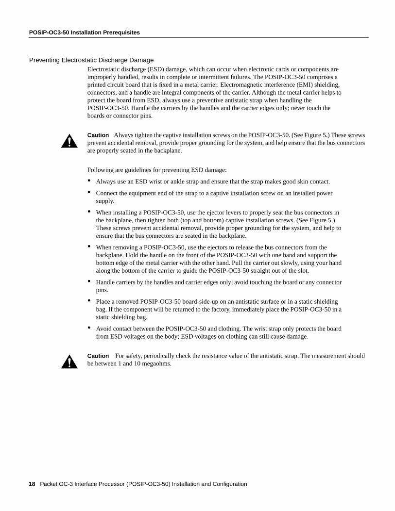
Preventing Electrostatic Discharge DamageElectrostatic discharge (ESD) damage, which can occur when electronic cards or components areimproperly handled, results in complete or intermittent failures. The POSIP-OC3-50 comprises aprinted circuit board that is fixed in a metal carrier. Electromagnetic interference (EMI) shielding,connectors, and a handle are integral components of the carrier. Although the metal carrier helps toprotect the board from ESD, always use a preventive antistatic strap when handling thePOSIP-OC3-50. Handle the carriers by the handles and the carrier edges only; never touch theboards or connector pins.
Caution Always tighten the captive installation screws on the POSIP-OC3-50. (See Figure 5.) These sprevent accidental removal, provide proper grounding for the system, and help ensure that the bus conare properly seated in the backplane.
Following are guidelines for preventing ESD damage:
• Always use an ESD wrist or ankle strap and ensure that the strap makes good skin contact.
• Connect the equipment end of the strap to a captive installation screw on an installed powersupply.
• When installing a POSIP-OC3-50, use the ejector levers to properly seat the bus connectors inthe backplane, then tighten both (top and bottom) captive installation screws. (See Figure 5.)These screws prevent accidental removal, provide proper grounding for the system, and help toensure that the bus connectors are seated in the backplane.
• When removing a POSIP-OC3-50, use the ejectors to release the bus connectors from thebackplane. Hold the handle on the front of the POSIP-OC3-50 with one hand and support thebottom edge of the metal carrier with the other hand. Pull the carrier out slowly, using your handalong the bottom of the carrier to guide the POSIP-OC3-50 straight out of the slot.
• Handle carriers by the handles and carrier edges only; avoid touching the board or any connectorpins.
• Place a removed POSIP-OC3-50 board-side-up on an antistatic surface or in a static shieldingbag. If the component will be returned to the factory, immediately place the POSIP-OC3-50 in astatic shielding bag.
• Avoid contact between the POSIP-OC3-50 and clothing. The wrist strap only protects the boardfrom ESD voltages on the body; ESD voltages on clothing can still cause damage.
Caution For safety, periodically check the resistance value of the antistatic strap. The measurement sbe between 1 and 10 megaohms.
18 Packet OC-3 Interface Processor (POSIP-OC3-50) Installation and Configuration

What Is the Cisco 7000 Series?
What Is the Cisco 7000 Series?The Cisco 7000 series consists of the Cisco 7000 and Cisco 7010 routers. The POSIP-OC3-50 willoperate in the Cisco 7000 series routers providing these routers have the 7000 Series Route SwitchProcessor (RSP7000) and 7000 Series Chassis Interface (RSP7000CI) installed. For Cisco IOSsoftware requirements, refer to the section “POSIP-OC3-50 Software Requirements” on page 12.Network interfaces reside on modular interface processors, including the POSIP-OC3-50, whichprovide a direct connection between external networks and the high-speed CxBus in the Cisco 7000series.
In the Cisco 7000, slot 5 is reserved for the RSP7000 (7000 RSP slot shown in Figure 7), whichcontains the system processor and performs packet switching functions, and slot 6 is reserved for theRSP7000CI (7000 CI slot shown in Figure 7), which contains all of the environmental monitoringfunctions for the Cisco 7000. The remaining five slots (slots 0 through 4) are for interface processors.
Figure 7 Cisco 7000 with RSP7000 and RSP7000CI Installed (Interface Processor End)
H52
88
Interface processor slots 0 1 2 3 4 RSP7000slot 5
RSP7000CIslot 6
Upper power supply
Lowerpower supply
I
O
DC FAILAC POWER
I
O
DC FAILAC POWER
Captiveinstallation screw
Captiveinstallation screw
EJECT
SLOT 0
SLOT 1
NORMAL
CPU HALTRESET
AUX.
CONSOLE
RO
UT
E S
WIT
CH
PR
OC
ES
SO
R
ENABLE
ENABLE
Packet OC-3 Interface Processor (POSIP-OC3-50) Installation and Configuration 19

POSIP-OC3-50 Installation Prerequisites
In the Cisco 7010, slot 3 is reserved for the RSP7000 (7000 RSP slot shown in Figure 8), whichcontains the system processor and performs packet switching functions, and slot 4 is reserved for theRSP7000CI (7000 CI slot shown in Figure 8), which contains all of the environmental monitoringfunctions for the Cisco 7010. The remaining three slots (slots 0 through 2) are for interfaceprocessors.
Figure 8 Cisco 7010 with RSP7000 and RSP7000CI Installed (Interface Processor End)
What Is the Cisco 7500 Series?The Cisco 7500 series consists of the Cisco 7505, Cisco 7507, and Cisco 7513 routers. ThePOSIP-OC3-50 will operate in all the Cisco 7500 series routers. For Cisco IOS softwarerequirements, refer to the section “POSIP-OC3-50 Software Requirements” on page 12. Networkinterfaces reside on modular interface processors, including the POSIP-OC3-50, which provide adirect connection between external networks and the high-speed CyBus in the Cisco 7500 series.
Figure 9, Figure 10, and Figure 11 show the rear of the Cisco 7500 series routers: the 5-slotCisco 7505, the 7-slot Cisco 7507, and the 13-slot Cisco 7513, respectively.
H58
74
RSP7000CI slot 4
RSP7000 slot 3
Interface processor slot 1
DC OK LEDPower switch
Chassis groundscrew
Power receptacle
Interface processor slot 2
Interface processor slot 0
AC-input power supply
EJECT
SLOT 0SLO
T 1
NORMALCPU H
ALT
RESET
AUX.
CONSOLE
ROUTE SWITCH PROCESSOR
ENABLE
ENABLE
20 Packet OC-3 Interface Processor (POSIP-OC3-50) Installation and Configuration
What Is the Cisco 7500 Series?
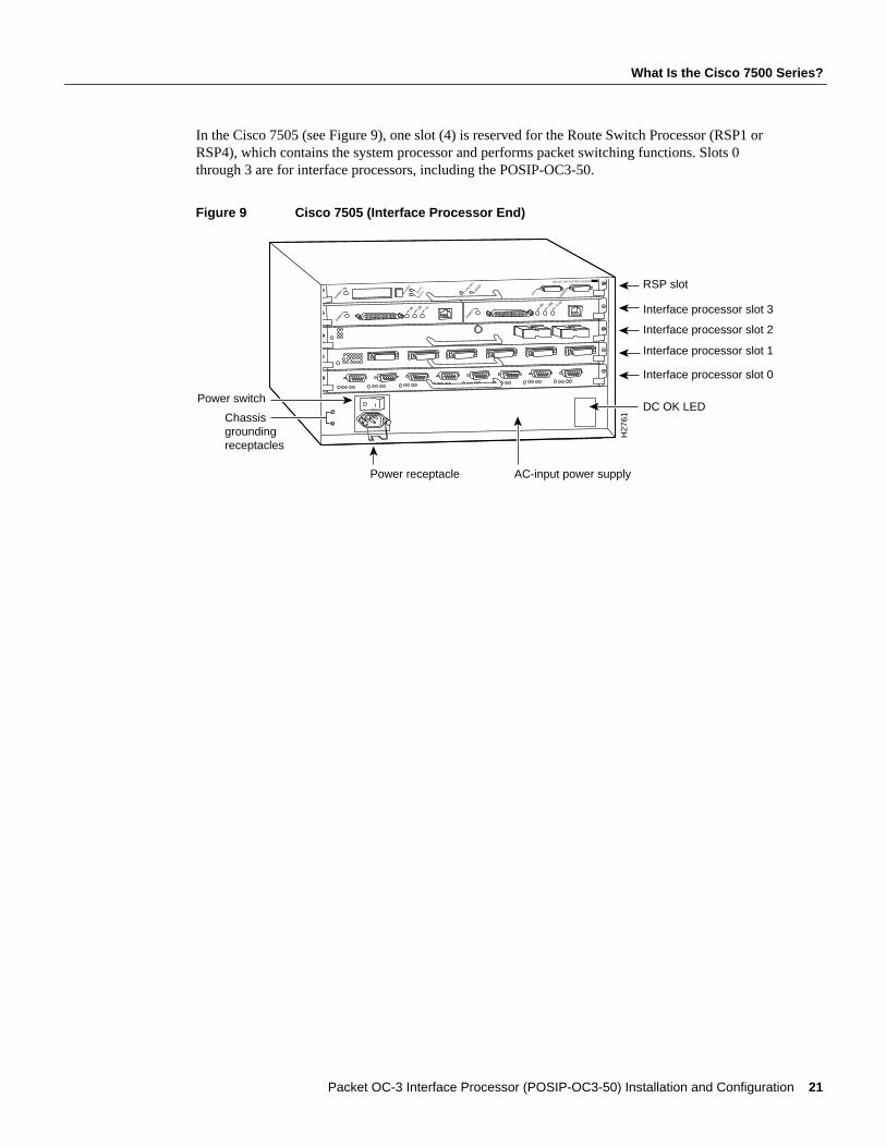
In the Cisco 7505 (see Figure 9), one slot (4) is reserved for the Route Switch Processor (RSP1 orRSP4), which contains the system processor and performs packet switching functions. Slots 0through 3 are for interface processors, including the POSIP-OC3-50.
Figure 9 Cisco 7505 (Interface Processor End)
H27
61
RSP slot
DC OK LEDPower switch
Chassisgrounding receptacles
Power receptacle AC-input power supply
EJECT
SLOT 0SLO
T 1
NORMAL CPU HALT
RESET
AUX.
CONSOLE
ROUTE SWITCH PROCESSOR
ENABLE
ENABLE
Interface processor slot 1
Interface processor slot 2
Interface processor slot 0
Interface processor slot 3
Packet OC-3 Interface Processor (POSIP-OC3-50) Installation and Configuration 21

POSIP-OC3-50 Installation Prerequisites
Figure 10 shows the rear of the seven-slot Cisco 7507 router. In the Cisco 7507, up to two slots (2and 3) are reserved for the Route Switch Processor (RSP2 or RSP4), which contains the systemprocessor and performs packet switching functions. Slots 0 and 1 and 4 through 6 are for interfaceprocessors, including the POSIP-OC3-50.
Figure 10 Cisco 7507 (Interface Processor End)
ENABLE
ENABLE
EJECT
SLOT 0
SLOT 1
NORMAL
CPU HALTRESET
AUX.
CONSOLE
RO
UT
E SW
ITC
H PR
OC
ESSO
R 2
SLAVE
MASTER
SLAVE/MASTER
H38
88
Slot 0 1 2 3 4 5 6
Upper power supply
Chassisgroundingreceptacles
Lowerpower supply
I
O
DC FAILAC POWER
I
O
DC FAILAC POWER
RSP slots
Captiveinstallation screw
Captiveinstallation screw
22 Packet OC-3 Interface Processor (POSIP-OC3-50) Installation and Configuration

What Is the Cisco 7500 Series?
Figure 11 shows the rear of the Cisco 7513 router. Two slots (6 and 7) are reserved for the RouteSwitch Processor (RSP2 or RSP4), which contains the system processor and performs packetswitching functions. Slots 0 through 5 and 8 through 12 are for interface processors, including thePOSIP-OC3-50.
Figure 11 Cisco 7513 (Interface Processor End)
ENABLE
ENABLE
H52
68
EJECT
SLOT 0
SLOT 1
NORMAL
CPU HALTRESET
AUX.
CONSOLE
RO
UT
E SW
ITC
H PR
OC
ESSO
R 2
SLAVE
MASTER
SLAVE/MASTER
Blower module
Cable-managementbracket
Card cage andprocessor modules
Air intake vent
Power supplies
Chassis groundingreceptacles 0
I
ACOK
FANOK
OUTPUTFAIL
0
I
ACOK
FANOK
OUTPUTFAIL
POWER
APOWER
B
Packet OC-3 Interface Processor (POSIP-OC3-50) Installation and Configuration 23

POSIP-OC3-50 Installation Procedures
. Also,rtingll
POSIP-OC3-50 Installation ProceduresThe following sections describe the procedures for removing or installing a POSIP-OC3-50 in aCisco 7000 series or 7500 series router. The online insertion and removal (OIR) feature allows youto install and remove a POSIP-OC3-50 without turning off system power; however, you must followthe insertion instructions carefully. For example, failure to use the ejector levers or insert thePOSIP-OC3-50 properly can cause system error messages indicating a board failure.
The function of the ejector levers on the POSIP-OC3-50 is to align and seat the card connectors inthe backplane. Failure to use the ejectors and insert the interface processor properly can disrupt theorder in which the pins make contact with the backplane. Follow the POSIP-OC3-50 installation andremoval instructions carefully, and review the following examples ofincorrect insertion practicesand results:
• Using the handle to force the interface processor all the way into the slot can pop the ejectors outof their springs. If you then try to use the ejectors to seat the interface processor, the first layer ofpins (which are already mated to the backplane) can disconnect and then remate with thebackplane, which the system interprets as a board failure.
• Using the handle to force or slam the interface processor all the way into the slot can also damagethe pins on the board connectors if they are not aligned properly with the backplane.
• When using the handle (rather than the ejectors) to seat the POSIP-OC3-50 in the backplane, youmight need to pull the POSIP-OC3-50 back out and push the POSIP-OC3-50 in again to alignthe pins properly. Even if the connector pins are not damaged, the pins mating with anddisconnecting from the backplane will cause the system to interpret a board failure. Using theejectors ensures that the board connector mates with the backplane in one continuous movement.
• Using the handle to insert or remove a POSIP-OC3-50, or failing to push the ejectors to the full90-degree position, can leave some (not all) of the connector pins mated to the backplane, a statewhich will hang the system. Using the ejectors and making sure that they are pushed fully intoposition ensures that all three layers of pins are mated with (or free from) the backplane.
Use the ejector levers when removing a POSIP-OC3-50 to ensure that the board connector pinsdisconnect from the backplane in the logical sequence expected by the system. Any RSP or interfaceprocessor that is only partially connected to the backplane can hang the bus. Detailed steps forcorrectly performing OIR are included with the following procedures for installing and removing aPOSIP-OC3-50.
Caution To avoid erroneous failure messages, remove or insert only one interface processor at a timeafter inserting or removing an interface processor, allow at least 15 seconds before removing or inseanother interface processor so that the system can reinitialize and note the current configuration of ainterfaces.
24 Packet OC-3 Interface Processor (POSIP-OC3-50) Installation and Configuration

Removing a POSIP-OC3-50
cause
Removing a POSIP-OC3-50If you are replacing a failed interface processor, remove the existing board first, then install the newinterface processor in the same slot.
Note In Cisco 7507 or Cisco 7513 systems, on-line insertion and removal of any interfaceprocessor in either CyBus might cause the slave RSP2 to reboot with a bus error or a processormemory parity error. The master RSP will recover from this event and issue a “cBus ComplexRestart” message. Cisco 7507 and Cisco 7513 systems that are configured with an RSP4 as thesystem slave are not affected and will not experience this problem.
If you have a Cisco 7507 or a Cisco 7513 with an RSP2 configured as the system slave, we stronglyrecommend that you use the following procedure to remove and replace an interface processor:
Step 1 Remove the slave RSP2.
Step 2 Wait 15 seconds.
Step 3 Remove and replace the interface processor using the procedures in this publication.
Step 4 Wait 15 seconds.
Step 5 Reinsert the slave RSP2.
Before you remove an interface processor that you will not replace, or replace an interface processorcomponent, we recommend you shut down (disable) the interfaces to prevent anomalies when youreinstall the new or reconfigured interface processor. When you shut down an interface, it isdesignatedadministratively downin theshowcommand displays. Figure 12 shows proper handlingof a POSIP during installation.
To remove a POSIP-OC3-50, follow these steps:
Step 1 Disconnect any interface cables from the ports on the front of the port adapter, although,this is not required. You can remove processor modules with cables attached; however,we do not recommend it.
Step 2 Slip on an ESD-preventive wrist strap and attach the strap to any unfinished surface onthe chassis.
Step 3 Use a screwdriver to loosen the captive installation screws on the ends of thePOSIP-OC3-50. (See Figure 12.)
Caution Always use the ejector levers to remove or install the POSIP-OC3-50. Failure to do so can erroneous system error messages indicating a board failure.
Step 4 Place your thumbs on the upper and lower ejectors and simultaneously push the topejector up and the bottom ejector down (in the opposite direction from that shown inFigure 5c) to release the POSIP-OC3-50 from the backplane connector.
Step 5 Grasp the POSIP-OC3-50 handle with one hand and place your other hand under thecarrier to guide the POSIP-OC3-50 out of the slot. (See Figure 12.) Avoid touching theboard or any connector pins.
Packet OC-3 Interface Processor (POSIP-OC3-50) Installation and Configuration 25

POSIP-OC3-50 Installation Procedures
. Also,rtingll
Figure 12 Handling a POSIP-OC3-50 During Installation (Horizontal Orientation Shown)
Step 6 Carefully pull the POSIP-OC3-50 straight out of the slot, keeping your other hand underthe carrier to guide the POSIP-OC3-50. (See Figure 12.) Keep the POSIP-OC3-50parallel to the backplane.
Step 7 Place the removed POSIP-OC3-50 on an antistatic mat or foam pad, or place thePOSIP-OC3-50 in an antistatic bag if returning the POSIP-OC3-50 to the factory.
Step 8 If the interface processor slot is to remain empty, install an interface processor filler(MAS7K-BLANK) to keep dust out of the chassis and to maintain proper airflow throughthe interface processor compartment.
Installing a New or Replacement POSIP-OC3-50 and Connecting InterfaceCables
The POSIP-OC3-50 slides into any available interface processor slot and connects directly to thebackplane. The backplane slots are keyed so that the POSIP-OC3-50 can be installed only in aninterface processor slot. Interface processor fillers, which are blank interface processor carriers,occupy empty slots to maintain consistent airflow through the interface processor compartment.
If you are installing a new POSIP-OC3-50, you will have to first remove the interface processor fillerfrom the available interface processor slot. Figure 5 shows the functional details of inserting aninterface processor and using the ejectors. Figure 12 shows proper handling of an interface processorduring installation.
Caution To avoid erroneous failure messages, remove or insert only one interface processor at a timeafter inserting or removing an interface processor, allow at least 15 seconds before removing or inseanother interface processor so that the system can reinitialize and note the current configuration of ainterfaces.
H47
14
Captive installation screws
26 Packet OC-3 Interface Processor (POSIP-OC3-50) Installation and Configuration

Installing a New or Replacement POSIP-OC3-50 and Connecting Interface Cables
y.
essorquently
ationmoval
Follow these steps to install a new or replacement POSIP-OC3-50:
Step 1 Ensure that a console terminal is connected to theConsoleport on the RSP, and that theconsole terminal is turned on. (This step is optional.)
Step 2 Choose an available interface processor slot for the POSIP-OC3-50, and ensure that theinterface cable is of a sufficient length to connect the POSIP-OC3-50 with the network.
Step 3 Interface processors and interface processor fillers are secured with two captiveinstallation screws. (See Figure 5.) Use a screwdriver to loosen the captive installationscrews and remove the interface processor filler (or the existing POSIP-OC3-50) from theslot. If you remove a POSIP-OC3-50, immediately place it into an antistatic bag toprevent damage from electrostatic discharge.
Step 4 Hold the POSIP-OC3-50 handle with one hand, and place your other hand under thecarrier to support the POSIP-OC3-50 and guide the carrier into the slot. (See Figure 12.)Avoid touching the card or any connector pins.
Caution To prevent ESD damage, handle interface processors by the handles and carrier edges onl
Step 5 Place the back of the POSIP-OC3-50 in the chassis slot and align the notch on the carrierwith the groove in the slot. (See Figure 5a.)
Step 6 While keeping the POSIP-OC3-50 parallel to the backplane, carefully slide thePOSIP-OC3-50 into the slot until the back of the faceplate makes contact with the ejectorlevers, thenstop. (See Figure 5b.)
Step 7 Using the thumb and forefinger of each hand to pinch each ejector, simultaneously pushthe levers inward (toward the handle) until they are parallel to the faceplate. (SeeFigure 5c.)
Caution To prevent system problems, always use the ejector levers when installing or removing procmodules. A module that is partially seated in the backplane will cause the system to hang and subsecrash.
Step 8 Use a 3/8-inch flat-blade screwdriver to tighten the captive installation screws on the endsof the POSIP-OC3-50. (See Figure 5.) (These screws must be tightened for maximumEMI protection.)
Caution To ensure that compliance with EMI standards is maintained, always tighten the captive installscrews on interface processors immediately after installation. Also, these screws prevent accidental reand provide proper grounding for the system.
Packet OC-3 Interface Processor (POSIP-OC3-50) Installation and Configuration 27

POSIP-OC3-50 Installation Procedures
hen
Step 9 Attach either two simplex fiber cables or one duplex fiber cable between the Packet OC-3interface port and your network. (See Figure 13 for the POSIP-OC3-50 orientationapplicable to your chassis type.) Ensure that you observe the receive (RX) and transmit(TX) cable relationship shown in Figure 13.
Figure 13 Attaching Simplex or Duplex Fiber Cables to the POSIP-OC3-50
Warning Invisible laser radiation may be emitted from the aperture ports of the single-mode products wno fiber cable is connected.Avoid exposure and do not stare into open apertures.
Warning Class 1 laser product.
Using LEDs to Check POSIP-OC3-50 StatusThe POSIP-OC3-50 has three LEDs on it faceplate that indicate status. (See Figure 14.)
Figure 14 POSIP-OC3-50 LEDs (Partial Faceplate View)
The enabled LED on the POSIP-OC3-50 and on all interface processors should go on. The consolescreen will also display a message as the system discovers each interface during its reinitialization.After system initialization, the enabled LED goes on to indicate that the POSIP-OC3-50 is enabledfor operation.
H10
550
SONET/SDH with simplex or duplex SC connectors
SONET/SDH with simplex or duplex SC connectors
Simplex (2)
To network
To network
POSIP-OC3-50in the Cisco 7010and Cisco 7505
POSIP-OC3-50 in the Cisco 7000, Cisco 7507, and Cisco 7513
Duplex (1)Simplex (2)
RX
TX
RX TX
Duplex (1)
ENABLED
155-
MMRX C
ARRIER
RX PACKETS PACKET OVER SONET/SDH
H64
66
28 Packet OC-3 Interface Processor (POSIP-OC3-50) Installation and Configuration
Using LEDs to Check POSIP-OC3-50 Status
The following conditions must all be met before the POSIP-OC3-50 is enabled:
• The POSIP-OC3-50 is correctly connected to the backplane and receiving power from thebackplane.
• The system bus recognizes the POSIP-OC3-50.
• A valid version of POSIP-OC3-50 microcode is loaded and running.
If any one of these conditions is not met, or if the initialization fails, the enabled LED does not go on.
The two status LEDs indicate the following:
• RX PACKETS—When on, indicates that the POSIP-OC3-50 has received a packet. This LEDwill flicker in normal operation, indicating traffic.
• RX CARRIER—When on, indicates that the POSIP-OC3-50 has detected valid SONET/SDHframing on the received carrier.
Verify that the POSIP-OC3-50 is connected correctly as follows:
Step 1 While the system reinitializes each interface, observe the console display messages andverify that the system discovers the POSIP-OC3-50. The system should recognize theOC3 interface but leave it configured asdown.
Step 2 When the reinitialization is complete, verify that the enabled LED on the POSIP-OC3-50is on and remains on. If the LED does stay on, proceed to Step 5. If the enabled LED doesnot stay on, proceed to the next step.
Step 3 If the enabled LED on the POSIP-OC3-50 fails to go on, suspect that the POSIP-OC3-50board connector is not fully seated in the backplane. Loosen the captive installationscrews, then firmly push the top ejector down while pushing the bottom ejector up untilboth are parallel to the POSIP-OC3-50 faceplate. Tighten the captive installation screws.After the system reinitializes the interfaces, the enabled LED on the POSIP-OC3-50should go on. If the enabled LED goes on, proceed to Step 5. If the enabled LED does notgo on, proceed to the next step.
Step 4 If the enabled LED still fails to go on, remove the POSIP-OC3-50 and try installing it inanother available interface processor slot.
• If the enabled LED goes on when the POSIP-OC3-50 is installed in the new slot,suspect a failed backplane port in the original interface processor slot.
• If the enabled LED still fails to go on, but other LEDs on the POSIP-OC3-50 go on toindicate activity, proceed to Step 5 to resume the installation checkout and suspect thatthe enabled LED on the POSIP-OC3-50 has failed.
• If no LEDs on the POSIP-OC3-50 go on, suspect that the POSIP-OC3-50 is faulty.
• If the enabled LED still does not go on, do not proceed with the installation. Contacta service representative to report the faulty equipment and obtain further instructions.
Step 5 Use theshow interfaces or show controllers cbus command to verify the status of theOC-3 interface. (If the OC-3 interface is not configured, you must configure it using theprocedures in the section “Configuring the POSIP-OC3-50.”)
If an error message displays on the console terminal, refer to the appropriate reference publicationfor error message definitions. If you experience other problems that you are unable to solve, contacta service representative for assistance.
Packet OC-3 Interface Processor (POSIP-OC3-50) Installation and Configuration 29

Configuring the POSIP-OC3-50
Configuring the POSIP-OC3-50This section describes the procedures for configuring the OC-3 interface on a POSIP-OC3-50. If youwant to change the configuration of an interface, you must enter configuration mode to makechanges. After you boot the system (and all cables are correctly connected and the enabled LED goeson), you can use theconfigure command to configure the new OC-3 interface.
Be prepared with the information you will need, such as the interface IP address, MTU size, framingmode, loopback modes (if testing is required), and clocking. On power up, the interface on a newPOSIP-OC3-50 is shut down. To enable the interface, you must enter theno shutdowncommand inconfiguration mode.
When the POSIP-OC3-50 is enabled (taken out of shutdown) with no additional arguments, thedefault interface configuration file parameters are as listed in Table 6.
Table 6 POSIP-OC3-50 Configuration Default Values
With the loop internal command, packets from the router are looped back in the framer. Outgoingdata gets looped back to the receiver without actually being transmitted. With theloop linecommand, the receive (RX) fiber is logically connected to the transmit (TX) fiber so that packetsfrom the remote router are looped back to it. Incoming data gets looped around and retransmittedwithout actually being received.
For additional descriptions of configuration subcommands and the configuration options availablefor Packet-Over-SONET, refer to the appropriate router system software configuration publicationslisted in the section “If You Need More Information” on page 2.
Configuring the POSIP-OC3-50 first requires privileged-level access to the EXEC commandinterpreter. Also, privileged-level access usually requires a password. (Contact your systemadministrator, if necessary, to obtain privileged-level access.)
Interface Port Numbering for the OC-3 InterfaceThe Cisco 7000 series and 7500 series routers identify an interface address by its interface processorslot number, port adapter number, and interface port number, in the formatslot/port-adapter/port.Each POSIP-OC3-50 contains a single (dual-width) port adapter and a single OC-3 interface;therefore, the port adapter number and interface port number are always 0/0. For example, theslot/port-adapter/port address of an OC-3 interface on a POSIP-OC3-50 installed in interfaceprocessor slot 0 would be 0/0/0; if installed in interface processor slot 1, the address changes to1/0/0.
Parameter Configuration Commands Default Value
MTU mtu bytes (no mtu bytes) 4470 bytes
Framing pos framing-sdh (no posip framing-sdh) SONET framing
Loopback internal loop internal (no loop internal) No internal loopback
Loopback line loop line (no loop line) No line loopback
Transmit clocking pos internal-clock Loop timing
SONET payload scrambling pos scramble-atm No scrambling
30 Packet OC-3 Interface Processor (POSIP-OC3-50) Installation and Configuration

Configuring the Interface
Configuring the InterfaceThis section describes guidelines for performing a basic configuration: enabling an interface andspecifying IP routing. You might also need to enter other configuration subcommands, depending onthe requirements for your system configuration and the protocols you plan to route on the interface.
In the following procedure, press theReturn key after each configuration step unless otherwisenoted.
Step 1 At the privileged-mode prompt, enter configuration mode and specify that the consoleterminal will be the source of the configuration subcommands as follows:
Router# configure terminalEnter configuration commands, one per line. End with CNTL/Z.Router(config)#
Step 2 At the prompt, specify the new interface to configure by entering theinterface posslot/port-adapter/portcommand:
Router(config)# interface pos 3/0/0
Step 3 Determine the configure commands available for the POSIP-OC3-50’s interface byenteringpos ? at the Interface mode prompt as follows:
Router(config-if)# pos ?posip framing-sdh select sdh framinginternal-clock Use internal clock for transmit clock sourcetransmitter-delay Set flag bytes to insert after transmitting a datagram
Use the preceding configuration commands according to your specific requirements andbased on their functions as described in the section “Customizing the POSIP-OC3-50Configuration,” on page 32, and in the appropriate software configuration publications.
Step 4 Determine theloopback commands available by enteringloop ? at the Interface modeprompt as follows:
Router(config-if)# loop ?internal internalline line
Use the preceding configuration commands according to your specific requirements andbased on their functions as described in the section “Customizing the POSIP-OC3-50Configuration,” on page 32, and in the appropriate software configuration publications.
Step 5 If IP routing is enabled on the system, you can assign an IP address and subnet mask tothe interface with theip address configuration subcommand, as in the followingexample:
Router(config-if)# ip address 1.1.1.3 255.255.255.0
Step 6 Change the shutdown state to up and enable the interface as follows:
Router(config-if)# no shutdown
Theno shutdown command passes anenable command to the POSIP-OC3-50. It alsocauses the POSIP-OC3-50 to configure itself based on the previous configurationcommands sent.
Step 7 Add any additional configuration subcommands required to enable routing protocols andadjust the interface characteristics.
Packet OC-3 Interface Processor (POSIP-OC3-50) Installation and Configuration 31
Configuring the POSIP-OC3-50
Step 8 When you have included all of the configuration subcommands to complete theconfiguration, enterCtrl-Z (hold down theControl key while you pressZ) to exitconfiguration mode.
Step 9 Write the new configuration to memory as follows:
Router# copy running-config startup-config[OK]
The system will display an OK message when the configuration has been stored.
For an explanation ofshow commands that allow you to check the interface configuration, refer tothe section “Using show Commands to Check the Configuration” on page 34. For additionalconfiguration options, proceed to the following section.
Customizing the POSIP-OC3-50 ConfigurationThe default values of all POSIP-OC3-50 configuration parameters can be changed to match yournetwork environment. Perform the tasks in the following sections if you need to customize thePOSIP-OC3-50 configuration:
• Selecting a POSIP-OC3-50 Interface on page 32
• Setting the MTU Size on page 32
• Configuring Framing on page 33
• Configuring an Interface for Internal Loopback on page 33
• Configuring an Interface for Line Loopback on page 33
• Setting the Source of the Transmit Clock on page 33
• Configuring SONET Payload Scrambling, page 33
Selecting a POSIP-OC3-50 InterfaceThe Packet OC-3 interface is referred to aspos in the configuration commands. An interface iscreated for each POSIP-OC3-50 found in the system at reset time. Before you can alter the interfaceconfiguration, you must select a specific Packet OC-3 interface using theinterface posslot/port-adapter/portcommand as follows:
Router(config)# interface pos x/y/z
wherex is the interface processor slot number and differs by the Cisco router in which thePOSIP-OC3-50 is installed,y is the port adapter slot (always 0), andz is the interface (always 0).
Setting the MTU SizeTo set the maximum transmission unit (MTU) size, use themtu byte command as follows:
Router(config-if)# mtu bytes
wherebytesis in the range of 64 through 4,470 bytes; the default is 4,470 bytes. (4,470 bytes exactlymatches the MTU of FDDI and HSSI interfaces for autonomous switching.)
Use theno mtu command to restore the default of 4,470 bytes:
Router(config-if)# no mtu
32 Packet OC-3 Interface Processor (POSIP-OC3-50) Installation and Configuration

Customizing the POSIP-OC3-50 Configuration
Configuring FramingThe default framing setting is SONET STS-3c. To configure for SDH STM-1, use theposframing-sdh command as follows:
Router(config-if)# pos framing-sdh
To change back to SONET STS-3c, use theno pos framing-sdhcommand.
Configuring an Interface for Internal LoopbackTo configure an interface for internal loopback, use theloop internal command as follows:
Router(config-if)# loop internal
Local loopback is useful for checking that the POSIP-OC3-50 is working. Packets from the routerare looped back in the framer.
Use theno loop internal command to disable internal loopback:
Router(config-if)# no loop internal
Configuring an Interface for Line LoopbackTo configure an interface for line loopback, use theloop line command as follows:
Router(config-if)# loop line
The receive fiber (RX) is logically connected to the transmit fiber (TX) so that packets from theremote router are looped back to it.
Use theno loop line command to disable line loopback:
Router(config-if)# no loop line
Setting the Source of the Transmit ClockBy default, the POSIP-OC3-50 uses the recovered receive clock to provide transmit clocking. Tospecify that the POSIP-OC3-50 generates the transmit clock internally, use thepos internal-clockcommands:
Router(config-if)# pos internal-clock
Use theno pos internal-clockcommand to restore loop timing:
Router(config-if)# no pos internal-clock
Configuring SONET Payload ScramblingSONET payload scrambling applies a self-synchronous scrambler (x^43+1) to the SynchronousPayload Envelope (SPE) of the POS interface to ensure sufficient bit t10ransition density.
Note Both ends of the connection must use the same scrambling algorithm.
To enable SONET payload scrambling on a POSIP, use thepos scramble-atminterface command.To disable SONET payload scrambling, use the no form of this command:no pos scramble-atm.This command has no keywords or arguments; the default is SONET payload scrambling disabled.
Packet OC-3 Interface Processor (POSIP-OC3-50) Installation and Configuration 33

Configuring the POSIP-OC3-50
To determine whether SONET payload scrambling is enabled on a POS interface, useshowstartup-config command; if enabled, the following line is displayed:pos scramble-atm .
(Also refer to the section “POSIP-OC3-50 Installation Prerequisites,” on page 11, for specifichardware and software requirements for using the SONET payload scrambling feature.)
The following example enables SONET payload scrambling on a POS interface:
Router(config)# interface pos 3/0/0Router(config-if)# pos scramble-atmRouter(config-if)# no shutdownRouter(config-if)# end
The following example disables SONET payload scrambling on a POS interface:
Router(config)# interface pos 3/0/0Router(config-if)# no pos scramble-atmRouter(config-if)# end
Using show Commands to Check the ConfigurationAfter configuring the new interface, use theshowcommands to display the status of the newinterface or all interfaces. Following are descriptions and examples ofshowcommands that displayPOSIP-OC3-50 information.
• Use theshow controllers cbus command to display the internal status of each interfaceprocessor, including the interface processor slot location, the card hardware version, and thecurrently running microcode version. Theshow controllers cbus command also lists eachinterface (port) on each interface processor, including the logical interface number, interfacetype, physical address, and hardware address of each interface.
The following example shows a POSIP-OC3-50 installed in interface processor slot 3:
Router# sh cont cbusMEMD at 40000000, 2097152 bytes (unused 1888, recarves 3, lost 0) RawQ 48000100, ReturnQ 48000108, EventQ 48000110 BufhdrQ 48000130 (2955 items), LovltrQ 48000148 (10 items, 1632 bytes) IpcbufQ 48000150 (24 items, 4096 bytes) 3570 buffer headers (48002000 - 4800FF10) pool0: 16 buffers, 256 bytes, queue 48000138 pool1: 229 buffers, 1536 bytes, queue 48000140 pool2: 332 buffers, 4480 bytes, queue 48000158 pool3: 4 buffers, 4512 bytes, queue 48000160
(additional displayed text omitted from this example)
slot0: VIP2, hw 2.3, sw 21.44, ccb 5800FF40, cmdq 48000090, vps 8192 software loaded from flash slot1:muck/biff/vip2_21-44 FLASH ROM version 255.255 POS3/0/0, applique is SONET gfreeq 48000158, lfreeq 48000168 (4480 bytes), throttled 0 rxlo 4, rxhi 332, rxcurr 0, maxrxcurr 0 txq 48001A00, txacc 48001A02 (value 221), txlimit 221
34 Packet OC-3 Interface Processor (POSIP-OC3-50) Installation and Configuration

Using show Commands to Check the Configuration
• Use theshow interfacesslot/port-adapter/interface command to discover information about aspecific interface in your system. Following is a sample of theshow interfacesslot/port-adapter/interfacecommand from a Cisco 7513 system with a POSIP-OC3-50 installedin interface processor slot 3:
Router# sh int pos 3/0/0POS3/0/0 is up, line protocol is up
Hardware is cyBus Packet over SonetInternet address is 1.1.1.1/27MTU 4470 bytes, BW 155000 Kbit, DLY 100 usec, rely 255/255, load 1/255Encapsulation HDLC, loopback not set, keepalive not setLast input 2d20h, output never, output hang neverLast clearing of “show interface” counters 2d00hQueueing strategy: fifoOutput queue 0/40, 0 drops; input queue 0/75, 0 drops5 minute input rate 0 bits/sec, 0 packets/sec5 minute output rate 0 bits/sec, 0 packets/sec
3600000 packets input, 1119432704 bytes, 0 no bufferReceived 0 broadcasts, 0 runts, 0 giants, 0 parity0 input errors, 0 CRC, 0 frame, 0 overrun, 0 ignored, 0 abort0 packets output, 0 bytes, 0 underruns0 output errors, 0 applique, 0 interface resets0 output buffer failures, 0 output buffers swapped out0 carrier transitions
• Use theshow diagbusslotcommand to view specific hardware information for a POSIP-OC3-50installed in your system. Following is an example of theshow diagbusslot command for aPOSIP-OC3-50 installed in interface processor slot 2:
Router# sh diag 2Slot 2:Physical slot 2, ~physical slot 0xD, logical slot 2, CBus 0Microcode Status 0x4Master Enable, LED, WCS LoadedBoard is analyzedPending I/O Status: NoneEEPROM format version 1VIP2 controller, HW rev 2.4, board revision B0Serial number: 03514213 Part number: 73-1684-03Test history: 0x00 RMA number: 00-00-00Flags: cisco 7000 board; 7500 compatible
EEPROM contents (hex): 0x20: 01 15 02 03 00 35 9F 65 49 06 94 03 00 00 00 00 0x30: 06 3C 00 2A 1A 00 00 00 00 00 00 00 00 00 00 00
Slot database information: Flags: 0x4 Insertion time: 0x1294 (00:13:39 ago)
Controller Memory Size: 32 MBytes DRAM, 1024 KBytes SRAM
PA Bay 0 Information: POS PA, 1 port EEPROM format version 1 HW rev 1.5, Board revision A0 Serial number: 00000032 Part number: 73-1803-04
• Use theshow protocols command to display the global (system-wide) and interface-specificstatus of any configured Level 3 protocol.
Packet OC-3 Interface Processor (POSIP-OC3-50) Installation and Configuration 35

POSIP-OC3-50 Statistics
• Use theshow running-configcommand to display the currently running POSIP-OC3-50configuration in RAM as follows:
Router# sh running-configinterface pos3/0/0
ip address 1.1.1.3 255.255.255.0ip route-cache distributedno keepaliveclock source internalpos scramble-atmcrc 16
• Use theshow versioncommand to display the configuration of the system hardware (the numberof each interface processor types installed), the Cisco IOS software version, the names andsources of configuration files, and the boot images.
Router# sh versionCisco Internetwork Operating System SoftwareIOS (tm) GS Software (RSP-JV-M), Released Version 11.1(14)CA [biff 100]Copyright (c) 1986-1996 by cisco Systems, Inc.Compiled Fri 10-May-96 06:48 by biffImage text-base: 0x600108A0, data-base: 0x60936000
ROM: System Bootstrap, Version 5.3(16645) [biff 571]ROM: GS Bootstrap Software (RSP-BOOT-M), Version 11.1(14)CA, RELEASE SOFTWARE (fc2)
Router uptime is 2 minutesSystem restarted by power-onSystem image file is “biff/rsp-jv-mz”, booted via tftp from 1.1.1.253
cisco RSP2 (R4600) processor with 16384K bytes of memory.R4600 processor, Implementation 32, Revision 2.0Last reset from power-onG.703/E1 software, Version 1.0.SuperLAT software copyright 1990 by Meridian Technology Corp).Bridging software.X.25 software, Version 2.0, NET2, BFE and GOSIP compliant.TN3270 Emulation software (copyright 1994 by TGV Inc).1 POSIP controller (1 POSI).1 Packet over Sonet network interface.125K bytes of non-volatile configuration memory.
8192K bytes of Flash PCMCIA card at slot 0 (Sector size 128K).8192K bytes of Flash internal SIMM (Sector size 256K).No slave installed in slot 7.Configuration register is 0x0
POSIP-OC3-50 StatisticsThe POSIP-OC3-50 will maintain a count of certain errors. Each POSIP-OC3-50 error counter is 32bits. Errors include the following:
• CRC errors—packet corrupted in transit
• Giants received—packet length too large (greater than 16 kilobytes [KB])
• Runts—packet length too small
• Ignores—no receive buffers available
36 Packet OC-3 Interface Processor (POSIP-OC3-50) Installation and Configuration

Packet-Over-SONET Error Messages
pareble isle will
Packet-Over-SONET Error MessagesThe only error message you should see would be of the following type and format:
%POSIP-0-MSG: %DEBUGGER-0-STACK_DATA8: 00E0 FFFFFFFF 80057F50 00000000 00000000FFFFFFFF 80032CD4 00000000 00000000
Note You should contact the Technical Assistance Center (TAC) for assistance with this errormessage. (To contact the TAC, refer to note that follows the section “Cisco Connection Online” onpage 48.)
Example of Two POSIPs Connected Back to BackThis section presents an example of two sample configuration files from two routers connected backto back through their OC-3 interfaces.
First router:
interface POS3/0/0ip address 1.1.1.1 255.0.0.0no keepaliveposip internal-clock
Second router
interface POS3/0/0ip address 1.1.1.2 255.0.0.0no keepalive
To connect two POSIP-OC3-50-equipped routers back to back, attach the appropriate cable betweenthe OC-3 interface port on each POSIP-OC3-50. By default, the POSIP-OC3-50 uses loop timingmode. To specify that the POSIP-OC3-50 generates the transmit clock internally, add theposip internal-clock command to your configuration.
Note For back-to-back operation, at least one of the POSIP-OC3-50smustbe configured to supplyits internal clock to the line.
Upgrading MicrocodeCisco 7000 series and Cisco 7500 series routers support downloadable microcode. You candownload new microcode versions and store multiple versions in Flash memory, and you can bootfrom them just as you can with the system software images. System software upgrades might alsocontain upgraded microcode images, which will load automatically when the new software image isloaded.
You can download microcode to Flash memory by copying the TFTP image of a microcode versionto Flash memory. When the microcode image is stored in Flash memory, you can use themicrocodereload command to manually load the new microcode file, and theconfigurecommand to instructthe system to load the new image automatically at each system boot.
Caution Before you copy a file to Flash, be sure there is ample space available in Flash memory. Comthe size of the file you want to copy to the amount of available Flash memory shown. If the space availaless than the space required by the file you wish to copy, the copy process will continue, but the entire finot be copied into Flash.
Packet OC-3 Interface Processor (POSIP-OC3-50) Installation and Configuration 37
Upgrading Microcode
To compare the size of the microcode image and the amount of Flash memory available, you mustknow the size of the new microcode image. The image size is specified in the README file that isincluded on the floppy disk with the new image. Note the size of the new image before proceedingto ensure that you have sufficient available Flash memory for the new image.
Follow these steps to copy a microcode version from the TFTP server to Flash memory:
Step 1 To display the total amount of Flash memory present, its location, any files that currentlyexist in Flash memory and their size, and the amount of Flash memory remaining, use theshow flash command. Following is an example of the output that is displayed:
Router# show flash4096K bytes of flash memory on embedded flash (in RSP1).file offset length name
[4085336/4194304 bytes free]
Step 2 Compare the amount of available Flash memory (last line in the preceding example) tothe size of the new microcode image on the floppy disk to ensure that there is sufficientspace available. If you attempt to copy in a new image, and the size of the new imageexceeds the available space in Flash, only part of the new image will be copied, and thefollowing error message will be displayed:
buffer overflow - xxxx/xxxx
wherexxxx/xxxx is the number of bytes read in/number of bytes available.
Step 3 After you verify that there is sufficient space available in Flash memory for the newimage, enter the following command at the privileged-level prompt:
Router# copy tftp flash
Step 4 Enter the IP address of the remote host:
IP address or name of remote host [255.255.255.255]? 1.1.1.106
Step 5 Enter the name of the file you want to copy to Flash (vip221-40in the following example):
Name of file to copy? v ip221-40
Step 6 To confirm that you want the file copied into Flash, pressReturn.
Copy vip221-40 from 1.1.1.106 into flash memory? [confirm]
If the correct file is not shown, enterno at the prompt to return to the system prompt andenter the correct file name.
Step 7 If you do not want Flash erased, enterno at the next prompt. If you accept the default toerase by pressingReturn without first typingno, the new image will write over the entirecontents of Flash memory, and you will lose all other microcode and system softwareimages stored in Flash.
Erase flash before writing? [confirm] no
While the file is copied to Flash, output similar to the following is displayed:
Loading from 1.1.1.106: !!!!!!!!!!!!!!!!!!!!!!!!!!!!!!!!!!!!!!!!!!!!!!!!!!!! [OK - 108966/4194304 bytes]Verifying via checksum...Flash verification successful. Length = 53364, checksum = 0x0000*
38 Packet OC-3 Interface Processor (POSIP-OC3-50) Installation and Configuration

Upgrading Microcode
Step 8 Use theshow flashcommand to verify that the microcode has been copied to Flash. Theoutput should display the file name of the image you copied to Flash (vip221-40in thefollowing example):
Router# show flash4096K bytes of flash memory on embedded flash (in RSP1).
file offset length name 1 0xD0D4 53364 vip221-40
[4085336/4194304 bytes free]
Step 9 To ensure that the new microcode is used when you reboot the system, add the appropriatecommands to the configuration file. To modify the configuration file, enter the followingcommand:
Router# configure terminalEnter configuration commands, one per line. End with CNTL/Z.Router(config)#
Step 10 Specify that you are changing the microcode for the POSIP-OC3-50 (microcode vip2),and that it will load from Flash memory(flash). Then add the filename of the newmicrocode image to be loaded from Flash:
Router(config)# microcode vip2 flash vip221-40
Step 11 To save the configuration file, pressCtrl-Z .
Step 12 Copy the new configuration to NVRAM as follows:
Router# copy running-config startup-config[OK]Router#
Themicrocode reload command is automatically added to your running configuration.The new CT3IP microcode image will load automatically the next time the system bootsor reinitializes.
Step 13 To load the new microcode immediately, you can instruct the system to load the newmicrocode by issuing themicrocode reload configuration command (you must be inconfiguration mode to enter this command):
Router# configure
Router(config)# microcode reload
Immediately after you enter themicrocode reload command and pressReturn, thesystem reloads all microcode. Configuration mode remains enabled; after the reload iscomplete, pressCtrl-Z to exit configuration mode and return to the system prompt.
Step 14 To verify that the POSIP-OC3-50 is using the correct microcode, issue theshowrunning-config, show startup-config,or show controller cbus commands. Theshowcontroller cbus display also indicates the currently loaded and running microcodeversion for each interface processor.
Router# show running-config
This completes the procedure for downloading microcode to Flash memory.
Packet OC-3 Interface Processor (POSIP-OC3-50) Installation and Configuration 39

Replacing POSIP-OC3-50 SDRAM and SRAM
42.)
Replacing POSIP-OC3-50 SDRAM and SRAMThis section provides the procedures for replacing the SDRAM dual in-line memory module(DIMM) and/or the SRAM daughter card on the POSIP-OC3-50 if a memory upgrade is indicated,or to replace the SDRAM or SRAM if a system problem has indicated their replacement. Dependingon your system configuration and the Cisco IOS your system is running, you might need to upgradeSDRAM or SRAM as required.
You can upgrade SDRAM and SRAM independently by ordering the appropriate memoryconfigurations. The following Cisco Systems memory kits are compatible with the POSIP-OC3-50:
• MEM-VIP250-8M-S=: upgrades a VIP2-50 to 8 MB of SRAM
• MEM-VIP250-64M-D=: upgrades a VIP2-50 to 64 MB of SDRAM
• MEM-VIP250-128M-D=: upgrades a VIP2-50 to 128 MB of SDRAM
Note You can use any combination of these SRAM and SDRAM configurations on the CT3IP-50.
The following sections describe upgrading SDRAM and SRAM:
• Replacing the POSIP-OC3-50 SDRAM DIMM
• Replacing the POSIP-OC3-50 SRAM Daughter Card, page 43
Replacing the POSIP-OC3-50 SDRAM DIMMThe procedures in this section are required only if you have a POSIP-OC3-50 and need to upgradeor replace the SDRAM DIMM.
Note Use only the SDRAM DIMM from Cisco Systems. A Cisco manufacturing part numberappears on the SDRAM DIMM.
Caution To prevent ESD damage, handle the DIMM by the card edges only. (See Figure 18 on pagePlace a removed DIMM on an antistatic mat and store it in an antistatic container.
Removing a POSIP-OC3-50 DIMMUse the following procedure to remove the existing DIMM:
Step 1 Turn OFF the system power and remove the VIP2--50 from the system. (Follow the stepsin the section “Removing a POSIP-OC3-50” on page 25.)
Step 2 Place the POSIP-OC3-50 on an antistatic mat or pad and ensure that you are wearing anantistatic device, such as a wrist strap. Position the POSIP-OC3-50 so that the handle isaway from you and the bus connector is toward you—opposite of the position shown inFigure 15.
Step 3 Locate the SDRAM DIMM. (See Figure 15.)
40 Packet OC-3 Interface Processor (POSIP-OC3-50) Installation and Configuration
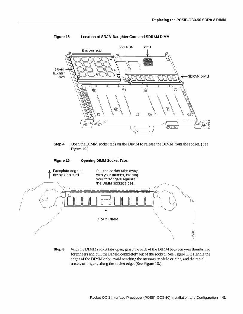
Replacing the POSIP-OC3-50 SDRAM DIMM
Figure 15 Location of SRAM Daughter Card and SDRAM DIMM
Step 4 Open the DIMM socket tabs on the DIMM to release the DIMM from the socket. (SeeFigure 16.)
Figure 16 Opening DIMM Socket Tabs
Step 5 With the DIMM socket tabs open, grasp the ends of the DIMM between your thumbs andforefingers and pull the DIMM completely out of the socket. (See Figure 17.) Handle theedges of the DIMM only; avoid touching the memory module or pins, and the metaltraces, or fingers, along the socket edge. (See Figure 18.)
H10
458
CPUBus connector
SRAM daughter
card SDRAM DIMM
Boot ROM
ENABLED
RX CARRIE
RRX P
ACKETS
155-MM
PACKET OVER SONET/SDH
DRAM DIMM
H10
448
Faceplate edge ofthe system card
Pull the socket tabs awaywith your thumbs, bracingyour forefingers againstthe DIMM socket sides.
Packet OC-3 Interface Processor (POSIP-OC3-50) Installation and Configuration 41
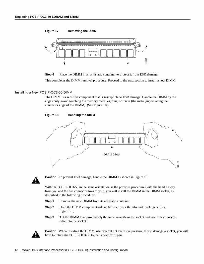
Replacing POSIP-OC3-50 SDRAM and SRAM
u will
Figure 17 Removing the DIMM
Step 6 Place the DIMM in an antistatic container to protect it from ESD damage.
This completes the DIMM removal procedure. Proceed to the next section to install a new DIMM.
Installing a New POSIP-OC3-50 DIMMThe DIMM is a sensitive component that is susceptible to ESD damage. Handle the DIMM by theedges only; avoid touching the memory modules, pins, or traces (the metalfingers along theconnector edge of the DIMM). (See Figure 18.)
Figure 18 Handling the DIMM
Caution To prevent ESD damage, handle the DIMM as shown in Figure 18.
With the POSIP-OC3-50 in the same orientation as the previous procedure (with the handle awayfrom you and the bus connector toward you), you will install the DIMM in the DIMM socket, asdescribed in the following procedure:
Step 1 Remove the new DIMM from its antistatic container.
Step 2 Hold the DIMM component side up between your thumbs and forefingers. (SeeFigure 18.)
Step 3 Tilt the DIMM to approximately the same an angle as the socket and insert the connectoredge into the socket.
Caution When inserting the DIMM, use firm but not excessive pressure. If you damage a socket, yohave to return the POSIP-OC3-50 to the factory for repair.
H10
450
DRAM DIMM
H10
449
42 Packet OC-3 Interface Processor (POSIP-OC3-50) Installation and Configuration
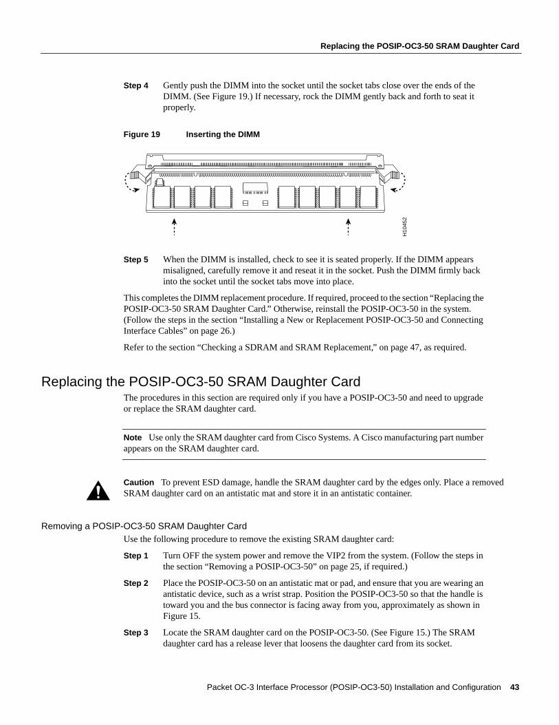
Replacing the POSIP-OC3-50 SRAM Daughter Card
ved
Step 4 Gently push the DIMM into the socket until the socket tabs close over the ends of theDIMM. (See Figure 19.) If necessary, rock the DIMM gently back and forth to seat itproperly.
Figure 19 Inserting the DIMM
Step 5 When the DIMM is installed, check to see it is seated properly. If the DIMM appearsmisaligned, carefully remove it and reseat it in the socket. Push the DIMM firmly backinto the socket until the socket tabs move into place.
This completes the DIMM replacement procedure. If required, proceed to the section “Replacing thePOSIP-OC3-50 SRAM Daughter Card.” Otherwise, reinstall the POSIP-OC3-50 in the system.(Follow the steps in the section “Installing a New or Replacement POSIP-OC3-50 and ConnectingInterface Cables” on page 26.)
Refer to the section “Checking a SDRAM and SRAM Replacement,” on page 47, as required.
Replacing the POSIP-OC3-50 SRAM Daughter CardThe procedures in this section are required only if you have a POSIP-OC3-50 and need to upgradeor replace the SRAM daughter card.
Note Use only the SRAM daughter card from Cisco Systems. A Cisco manufacturing part numberappears on the SRAM daughter card.
Caution To prevent ESD damage, handle the SRAM daughter card by the edges only. Place a remoSRAM daughter card on an antistatic mat and store it in an antistatic container.
Removing a POSIP-OC3-50 SRAM Daughter CardUse the following procedure to remove the existing SRAM daughter card:
Step 1 Turn OFF the system power and remove the VIP2 from the system. (Follow the steps inthe section “Removing a POSIP-OC3-50” on page 25, if required.)
Step 2 Place the POSIP-OC3-50 on an antistatic mat or pad, and ensure that you are wearing anantistatic device, such as a wrist strap. Position the POSIP-OC3-50 so that the handle istoward you and the bus connector is facing away from you, approximately as shown inFigure 15.
Step 3 Locate the SRAM daughter card on the POSIP-OC3-50. (See Figure 15.) The SRAMdaughter card has a release lever that loosens the daughter card from its socket.
H10
452
Packet OC-3 Interface Processor (POSIP-OC3-50) Installation and Configuration 43

Replacing POSIP-OC3-50 SDRAM and SRAM
ughterr card
Caution To prevent damage to the SRAM daughter card in the steps that follow, donotopen the release leveron the daughter card’s socket until after you remove the three screws located at the rear of the SRAM dacard. (See Figure 20.) Further, do not reinstall the three screws until after you install the SRAM daughtein the socket, and ensure that the release lever is flush against the side of the socket.
Figure 20 Locations of Screws on the SRAM Daughter Card and the Release Lever
Note Figure 21 and Figure 22 show the functions of the release lever on the SRAM daughter cardsocket. To release an SRAM daughter card from the socket, first remove the three screws,thenopenthe release lever, as shown in Figure 21. When you insert an SRAM daughter card in the socket, therelease lever should close automatically, as shown in Figure 22.
Figure 21 Opening the Release LeverH
1045
3
Motherboard
Open the release lever after you remove the three screws.Ensure the release lever is closed before you reinstall the three screws.
Remove thesescrews first and reinstall them last
1
2
Bus connector
Socket
H10
455
44 Packet OC-3 Interface Processor (POSIP-OC3-50) Installation and Configuration

Replacing the POSIP-OC3-50 SRAM Daughter Card
Figure 22 Ensuring the Release Lever is Closed
Step 4 Locate the three screws that secure the SRAM daughter card to the motherboard. (Seeitem 1 in Figure 20.)
Note The SRAM daughter card lays parallel to the motherboard when the daughter card connectoredge is installed in the socket.
Step 5 Using a Number 1 Phillips screwdriver, carefully remove the three screws from theSRAM daughter card (see Figure 20), then set them aside.
Step 6 Locate the release lever on the socket. (See Figure 20.) Open the release lever to releasethe SRAM daughter card from the socket.
Step 7 When one end of the SRAM daughter card is released from the socket, carefully pull thecard away from the socket and motherboard. Handle the edges of the SRAM daughtercard only. (See Figure 23.)
Figure 23 Handling an SRAM Daughter Card
Step 8 Place the SRAM daughter card in an antistatic container to protect it from ESD damage.
This completes the SRAM daughter card removal procedure. Proceed to the next section to install anew SRAM daughter card.
H10
456
H10
154
Packet OC-3 Interface Processor (POSIP-OC3-50) Installation and Configuration 45
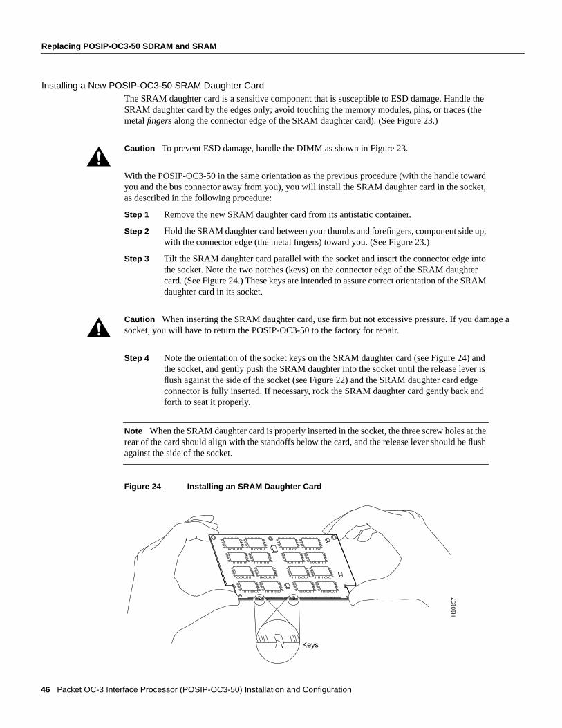
Replacing POSIP-OC3-50 SDRAM and SRAM
e a
Installing a New POSIP-OC3-50 SRAM Daughter CardThe SRAM daughter card is a sensitive component that is susceptible to ESD damage. Handle theSRAM daughter card by the edges only; avoid touching the memory modules, pins, or traces (themetalfingers along the connector edge of the SRAM daughter card). (See Figure 23.)
Caution To prevent ESD damage, handle the DIMM as shown in Figure 23.
With the POSIP-OC3-50 in the same orientation as the previous procedure (with the handle towardyou and the bus connector away from you), you will install the SRAM daughter card in the socket,as described in the following procedure:
Step 1 Remove the new SRAM daughter card from its antistatic container.
Step 2 Hold the SRAM daughter card between your thumbs and forefingers, component side up,with the connector edge (the metal fingers) toward you. (See Figure 23.)
Step 3 Tilt the SRAM daughter card parallel with the socket and insert the connector edge intothe socket. Note the two notches (keys) on the connector edge of the SRAM daughtercard. (See Figure 24.) These keys are intended to assure correct orientation of the SRAMdaughter card in its socket.
Caution When inserting the SRAM daughter card, use firm but not excessive pressure. If you damagsocket, you will have to return the POSIP-OC3-50 to the factory for repair.
Step 4 Note the orientation of the socket keys on the SRAM daughter card (see Figure 24) andthe socket, and gently push the SRAM daughter into the socket until the release lever isflush against the side of the socket (see Figure 22) and the SRAM daughter card edgeconnector is fully inserted. If necessary, rock the SRAM daughter card gently back andforth to seat it properly.
Note When the SRAM daughter card is properly inserted in the socket, the three screw holes at therear of the card should align with the standoffs below the card, and the release lever should be flushagainst the side of the socket.
Figure 24 Installing an SRAM Daughter Card
H10
157
Keys
46 Packet OC-3 Interface Processor (POSIP-OC3-50) Installation and Configuration

Checking a SDRAM and SRAM Replacement
Step 5 Verify that the three screw holes at the rear of the SRAM daughter card align with thestandoffs below the SRAM daughter card; using the Number 1 Phillips screwdriver,reinstall the three screws. (See Figure 20.)
Step 6 After you install the three screws, ensure that the release lever is flush against the side ofthe socket. If it is not, the SRAM daughter card might not be seated properly. If the SRAMdaughter card appears misaligned, carefully remove it according to the removal procedureon page 43, and reseat it in the socket. Push the SRAM daughter card firmly back into thesocket until the release lever is flush against the side of the socket.
Step 7 Reinstall the POSIP-OC3-50 in your system. (Follow the steps in the section “Installinga New or Replacement POSIP-OC3-50 and Connecting Interface Cables” on page 26.)
This completes the SRAM daughter card replacement procedure.
Checking a SDRAM and SRAM ReplacementIf, after a SDRAM or SRAM replacement, the system fails to boot properly, or if the consoleterminal displays a checksum or memory error, check the following:
Ensure that all memory devices are installed correctly. If necessary, shut down the system andremove the POSIP-OC3-50. If a memory device appears to stick out or rest in the socket at anincorrect angle, remove it and reinsert it. Then replace the POSIP-OC3-50 and reboot the system foranother installation check.
Refer to the section “Using LEDs to Check POSIP-OC3-50 Status,” on page 28, as required. If afterseveral attempts the system fails to restart properly, contact a service representative for assistance.Before you call, make note of any error messages, unusual LED states, or any other indications thatmight help solve the problem.
Packet OC-3 Interface Processor (POSIP-OC3-50) Installation and Configuration 47

Cisco Connection Online
t,
Cisco Connection OnlineCisco Connection Online (CCO) is Cisco Systems’ primary, real-time support channel. Maintenancecustomers and partners can self-register on CCO to obtain additional information and services.
Available 24 hours a day, 7 days a week, CCO provides a wealth of standard and value-addedservices to Cisco’s customers and business partners. CCO services include product information,product documentation, software updates, release notes, technical tips, the Bug Navigator,configuration notes, brochures, descriptions of service offerings, and download access to public andauthorized files.
CCO serves a wide variety of users through two interfaces that are updated and enhancedsimultaneously: a character-based version and a multimedia version that resides on the World WideWeb (WWW). The character-based CCO supports Zmodem, Kermit, Xmodem, FTP, and Internete-mail, and it is excellent for quick access to information over lower bandwidths. The WWW versionof CCO provides richly formatted documents with photographs, figures, graphics, and video, as wellas hyperlinks to related information.
You can access CCO in the following ways:
• WWW: http://www.cisco.com
• WWW: http://www-europe.cisco.com
• WWW: http://www-china.cisco.com
• Telnet: cco.cisco.com
• Modem: From North America, 408 526-8070; from Europe, 33 1 64 46 40 82. Use thefollowing terminal settings: VT100 emulation; databits: 8; parity: none; stop bits: 1; andconnection rates up to 28.8 kbps.
For a copy of CCO’s Frequently Asked Questions (FAQ), contact [email protected]. Foradditional information, contact [email protected].
Note If you are a network administrator and need personal technical assistance with a Ciscoproduct that is under warranty or covered by a maintenance contract, contact Cisco’s TechnicalAssistance Center (TAC) at 800 553-2447, 408 526-7209, or [email protected]. To obtain generalinformation about Cisco Systems, Cisco products, or upgrades, contact 800 553-6387,408 526-7208, or [email protected].
This document is to be used in conjunction with the router installation and configuration guide that shipped with your router. (4560pos3.fm[78-4560-02])
AccessPath, AtmDirector, the CCIE logo, CD-PAC, Centri, Centri Bronze, Centri Gold, Centri Security Manager, Centri Silver, the Cisco Capital logo, Cisco IOS, the Cisco IOS logo,CiscoLink, the Cisco Powered Network logo, the Cisco Press logo, ClickStart, ControlStream, Fast Step, FragmentFree, IGX, JumpStart, Kernel Proxy, LAN2LAN Enterprise, LAN2LANRemote Office, MICA, Natural Network Viewer, NetBeyond, Netsys Technologies,Packet, PIX, Point and Click Internetworking, Policy Builder, RouteStream, Secure Script, SMARTneStrataSphere, StrataSphere BILLder, StrataSphere Connection Manager, StrataSphere Modeler, StrataSphere Optimizer, Stratm, StreamView, SwitchProbe,The Cell, TrafficDirector,VirtualStream, VlanDirector, Workgroup Director, Workgroup Stack, and XCI are trademarks; Empowering the Internet Generation and The Network Works. No Excuses. are servicemarks; and BPX, Catalyst, Cisco, Cisco Systems, the Cisco Systems logo, EtherChannel, FastHub, FastPacket, ForeSight, IPX, LightStream, OptiClass, Phase/IP, StrataCom, andStrataView Plus are registered trademarks of Cisco Systems, Inc. in the U.S. and certain other countries. All other trademarks mentioned in this document are the property of their respectiveowners.
Copyright © 1997–1998, Cisco Systems, Inc.All rights reserved. Printed in USA.9801R
48 Packet OC-3 Interface Processor (POSIP-OC3-50) Installation and Configuration