Embed Size (px)
Citation preview

--
400 Commonwealth Drive, Warrendale, PA 15Q96-900% U.S.A. Tel: (724) 7764845 Fax: (724) 376-5360 Web: www.sae.org

Afl rights reserved. No part of this publication may be reproduced, stored in a retrieval system, or transmitted, in any dorm or by any means, electronic, mechanical, photocopying, recording, or otherwise, wiEhctut the prior written permission of SAE.
For permission and licensing requests contact:
SAE Permissions 480 Commonwealth Drive Warrendale, PA 1 %@6-O08% -USA Email: [email protected] Fax: 724-772-4028 Tel: 724-772-4891
All SAEpapers, standards, and selected books are abstracted and indexed in the Global Mobility Dafabase
For multiple print copies contact:
SAE Ctrstamer Service T i : G77-686-7323 (inside USA and Canada) Tek 724-776-4970 (outside USA) Fax: 724-776-1 61 5 Email: [email protected]
15SN 0148-7491 Copyright O 2083
Positions and opinions advanced in this paper are those of the author(s) and not necessarily those of SAE. The author is solely responsible for :he contant of the paper. R process is available by which discussions will be printed with the paper if it is published in SAE Transactions.
Persons wishing to submit papers to be mnsidered for presentation or publication by SAE shouici send the manuscript or a 30Q word abstract of a proposed manuscript to: Secretary, Engineering Meetings Board, SAE.

3
Copyright O 2003 SAE lnterrialional
The gas-nitriding characteristics of valve springs made from three different grades of oii-tempered wires were investigated as a preliminary study, and the springs made from the most heat resistant grade of oil-tempered wire (SGTHS) weie selected for further stidy. As a result, fatigue Emit strength as high as 736MPa (mean stress) +/- 665MPa (amplitude stress) at a stress repetion of 5x1Q7 cycles was obtained by applying gas- nitriding, foflowed by multi-stage shot-peening, the fast stage of which was very fine steel bead peening with the average sire less than 50 pm (SS-Treatment). The reasons far the high fatigue endurance obtained are also discussed,
in the previous papers by the present authors, it was reported that considerahie improvement in both fatigue strength and surface compressive residua! stress can be obtained by peening with fine steel beads with the mean diameter less than @ 50 Vm (This treatment is also referred to as "SS-Treatment" in this paper) to the normal shot-peened (with @O,Gmm diameter cut steel wires) non-nitrided high strength SQTWN wire valve springs [ I ] , to the normally shot-peened gas-nitrided high strength SQTHN wire valve springs or to the normally shot-peened gas-nifrided high strength SOTHS wire valve springs 121. More precisely, the average diameter and the average hardness of the fine shot particles used in the SS-Treatment for the second shot- peening in these papers were reported as 643 +urn and around HV 850, respectively. In the first part of the present paper, heiical springs made from different vaive spring steel wire grades, i.e., the conventions! JIS SWQSC-V wire (Valve spring quality CrSi steei oil- tempered wire, where CrSi steel is identical to the stee! grade SAE9254.) and two kinds of high strength valve spring quality steel wires, i.e., SOTMN [I, 2j wire and the
SOTHS wire 12, 31, were gas-nitrided under the same conditions and the effects of these three kinds of different steel wire grades on the resultant
nitriding characteristics were investigated. Since it was found that the now high strength grade SQTHS wire vdve springs nitrided had the highest surface layer and core hardness among these three grades of wires, and as a resuIt gave the besf resistance to the stress relaxation of the nitrided springs, only the high strength SQTHS wire valve springs were used for the following fatigue research However, in the last paper by the present authors M, since the gas-nitrided and two stage shot-peened high strength SQTHS wire valve springs (i.e., conventional shot-peening followed by SS- Treatment) were reported to be free of fatigue-fracture even after repetition in the highest stress range as high as Tm 686MPa (m: mean shear stress) +/- Ta S67MPa (aa: amplitude shear stress), the so-called S-N curve and the fatigue limit stress could not be obtained. The hardness and residual stress distributions in these nitrided and two stage shot-peened SOWS wire springs, which were not included in the previous paper 621, are reported in the present paper. Then, in the present fatigue research, the wire diameter and the dimensions of the SOTHS wire springs to be used for fatigue testing were selected so as to allow fatigue-testing at higher stress levels than the 43.2mm SQTHS wire nitrided springs reported in the previous paper [2], and at the same time, in order to successfully obtain an S-hl ctrrve, Also in the present study, the nitriding condition was modified to such an extent that higher core hardness can be obtained compared with the springs reported in the previous paper. Specificatly, the nitriding temperature was decreased to 703K and the time was shortened to 3hrs in the present research, compared with 723K and 7hrs in the previous investigation p]. In the previous paper by the present authors [2], the first- step shot-peening after gas-nitriding was performed using cut steel wires with a diameter of 4 0.6rnm. The shot-peening condition was aiso modified in the present study from the condition adopted in the last paper 221 in order to get coinpressit-e residual stress deeper ii? the spring surface layer. In the final stage, the SS-Treatment was applied. As a result, at the stress repetition of 5x10' cycles, fatigue limit stress as high as 736MPa +/- 687MPa or 736MPa +i- 665MPa was obtained from the

S-Rf curve or by the Probit method, respectively. The residual stress and hardness distributions, and also the surface roughness were measured. Rased on these investigatians, the reasons for the high fatigue strength obtained are discussed in the latter part of this paper.
3 TESTED MATERIALS
The wire grades used in the first part of this study were conventional grade wire JIS SW8SC-V, two high strength grade SOTHN and SOWS wires. Afi of these wires were manufactured on the normal valve spring wire production line in the Kyoto Plant, Suncall Carp, as valve spring quality wires, i.e., hot rolled wire rods (raw materials) were surface shaved, heal-treated, acid- pickled, wire-drawn to final diameters and ail-tempered. The chem~cal compositions of these wires are iiisted In Tabk 1. The supplied SWOSC-V and SOTHN wires
Table 1. Chemical compositions of wires used Mass %
l I i r e l S i Grade
S W O S ~ c55 1.40
(9254)
- I able 2. Tenslie strengths of different grade wires used
mm fracture "/b
had a diameter of @3.2mm and the SOTHS wire $4.13mm. In addition to these wires, the chemical composition of anather SOPHS wire with a diameter sf (1,3.2mm, which
was studied in a previous report PI, is listed in Tabfe 1. The tensile strengths of these wires as-supplied s;re given in Table 2 except the 4 3.2mrn SOTHS wire.
EXPERIMENTAL METHODS
f2 #, u,s-nit;ibin~ characteristics of springs made drorr; three grades of steel wires
In order to study the effect of steeb wire grade on gas- nitriding characteristics, three kinds of wires listed in Tabie 2 were cold-wound to helical springs, stress-relief tempered at 708M for 20min, descaled, gas-nifrided at T03K for 180min, shot-peened and tempered for strajn aging at 493K for 20min. The dimensions of the springs produced are listed in Table 3, The shot-peening condition lor the SWOSC-V, and SOTHN wire springs was as follows: Cut steel wires with a diameter of
Table 3. Dimensisns of springs tested
Wire grade ~ ~ , " - ~ / - s ~ ~ ~ - ~
- Wive diameter fmm)
Mean coil (mm)
(turns)
(turns) I I
Free height (mm)
@0.6mrn and a hardness of HV 550 were shot on the spring surface at a speed of 72mlsec for 40min. Far the $ 4.0mm SOTMS springs, more intense shot-peening was applied by using @ 0.8mm round cut steel wires with high hardness, and in the final-stage, the SS-Treatment was practiced for 20min. After :he shot-peening, a!! the springs were tempered at 493K for 20min for strain aging and then cold pre-set at 1,294MPa. Using these finished springs, the hardness and nitrogen distributions at the surface layers were investigated, and the stress relaxahians were tested by spring clamping tests. In measuring hardness distributions, the chord method I31 was applied and a micro-'dickers hardness tester was used for hardness measurement. The bad appjied for the hardness indentation was 2.94N (300grf) except for the outermost surface indentation where a 0.9861 (100gi-f) load was applied. The nitrogen distributions in the surface layer were analyzed using an X-ray micro- analyzer, type JM-8800Rl- from JEOL. The measurement of She nitrogen content in the spring

surface layer was made on a polished cross section o l each spring in terms of the Iine analysis rnethod starting from the spring surface to a depth of approximately 0.14mm below the surface, under the condition of the electron beam acceleration voltage of 15kV and a current of 0.3 p4. The spring clamping tests were conducted as-foliows: The test springs were compressed to a predeterniined height with a steef nut and bolt, were then held in an oven kept at 393K for
3 48hrs and then cooled to room temperature. After that, the !oar8 Ioss AP of the tested spring brought about by the heating at 393K for 48hrs was measured and the y (in Japan, y is called "residual shear strain", that is proportional to the load loss AP and means the elastic shear strain caused by the bad loss AP if it occurred a l due to elastic deformation, or the shear stress relaxation divided by shear modulus.) was calculated as follows;
Where D: Mean spring diametef
AP: Load loss
d: Wire diameter
G: Shear modulus
Sprina fatigue test
Foliowiiig the experimenSaB studies to compare the properties of tho nitrided springs described above, the most heat resistant 4 4mm SOTWS wire nitrided springs with the best characteristics were fatigue-tested, of which the produetion processes were the same as those explained in the previous paragraph. The spring fatigue tests were pedormed using hydraulic servo-pulser type machines. The speed of stress cycling was 1,200rpm. Each fatigue test was conducted until 5~10 ' cycles when no fracture took place during the test.
Hardness measurement by Nano-Indenter
In the measurement of hardness distributions across an adiabatic shear band using a nano-indenter XP from MPS systems Coap., each hardness was determined at an indentation depth of 300nm betow the specimen surface during indentation sf a diamond triangular cone (called Berkovich indenter) under vibration 141.
Residrnai stress distributions
Residual stresses were measured using a PSPC micro- area X-ray residual stress analyzer from Rigaktr Corporation. Chromium Kcx irradiation and (211) a-iron X-ray diffraction peaks were used for the anaiyses.
STEEL WIRE GRRDES AND THE NITRIDING CHAPJ\CTERISTICS
Nitrogen content in the surface fayer in each gas-nrtrided spring is shown In Figure 1 It was found that the depth ot the nitrogen penetration beneath the spring surface or the thickness sf the nitrided layer is around 89 pm irrespective of the wire grades tested The nitrogen contents in the outermost surface layers were found to be approximate[y 1.9, 3.0, and 6.9 mass O h for the SWOSC-V, SOTMN, and SOTHS wire springs, respectively. This indicates that in the outermost surface layers of all the nitrided springs rn Figure 9 , iron nitride (probably E-iron nitride Fe2,N) par2icles ar~dlor layers were formed (pure cison nitride contains approximately 7.7 to 11.1 mass "/o nitrogen, according tothe chemical cornposrtinn ranging from Fe,N to Fe,N) since percentage of nkogen in solid solution in a iron is far less khan 1.9 mass%. The hardness distributions measured for different steek wire grade springs nitrrded
Figure? I. Nitrogen contents in the surface iayer by linear an&sis with an X-ray micro-analyzer
1000
Figure 2. Micro Vickers hardness distributions in gas- nitrided springs. (Nitriding condition: 7Q3K for Shrs, load: 0.38N for the outermost surface indentations, and 2.94N for other indentations)

at: 7O3K for 3hr, shot-peened, tempered for strain aging, and pre-set are shown in Figure 2. It was found that the SOTHS, the SOTHN, and the SVVOSC-V fCrSi steet) wire springs have core hardnesses of approxrmately t-fV550, l-iV530, and 1-1V498, respectively. When comparing the surface hardness among these three kinds of springs, the SOTHS spring has the highest value and the SWOSC-W spring has the lowest value. It should be noted that the hardness near the spring surface is infl~tenced not only by
3 the nitrogen content but also by the shot-peening condition. According to Y. ebki el a! 151, of alll the tensile strengths obtained after heating, quenching to oil, and tempering at a ceheain condition, the highest tensile strength obkained was in the steel grade equivalent lo the SOTHS wire, followed by the high-carbon SAE 92 wire that was not tested in the present study, and the SAE92N wire that is equivalent to the SWOSC-V wire, had the lowest tensile strength anlong the three grades of steels tested. The increased amount of carbon, chromium, vanadium, and silicon in SQTHS wire compared with the other steel wires is reported to contribute to the increased high hardness i5]. Some of these nitrided springs made from the three kinds of wire grades in this study were subjected to the spring clamping test at 393K far 48hrs and their stress relaxation properties were checked. Figure 3 shows the results obtained. Piotited data in this figure clearly indicate the superiority of the nitrided SOTHS wire springs compared with the other grades of wire springs, Preserving a high hardness in the core portion in the gas-nitriding process is considered ta be an
excellent resistance to stress
over-peened SOTHS wire spring, It clearly shows a micro-crack generated along an white-etch~ng adiabatic shear band [6, 77, existent in the non-nitrided spring surface layer. This kind of adiabatic shear band is a trace of locaked shear deformation in metais and a k y s as a resuft of high-strain-rate cold working to farge piastic strain. Hardness traverses by a nano indenter were made across an adiabatic shear band in an over- peened SOTHS wire spring, and the results are plotted
Figure 4. An exarnpIe of a micro-crack produced in a SOTHS wire spring by over-peening (an optical micro- graph sf a wire cross section nital-etched).
1 3 4 5 6 7 8 9 1 0 1 1 1 2 1 3 M easuvem ent. po'nt num ber
14 15 16 17 18 19 20 21 22 23 24 25 26 M easurern en t pont num ber
500 600 700 800 900 1000 1300 1200 C Bm p ~ g shear stress M Pa
Figure 3. Spring clamping test results for gas-nitrided springs made from different wire grades (393K, 48hrs)
PREVENTION OF MICRO CRACKS FORMATION i SHOT-PEENING
It is we81 krrown among engineers specializing in spring technology that springs shoi-peened with particfes with an excess kinetic energy normally end up with inferior fatigue strength and rougher spring surface than springs shot-peened under proper conditions. Such an over- intense shot-peening is sometimes called over-peening. Figure 4 shows an example of a cross section of an
Figure 5. Hardness distributions across a shear band by a nano indenter (upper figures) and the corresponding SEM image with indentations for the hadness measurements (lower photo.). A dark-colored vertical line crossing the point 6 is the shear band. The right hand side in the SEM image is the surface.
along with an SEM image in Figure 5. The nu~nericai numbers in the SEM image indicate indentations corresponding to the measurement point numbers in the hardness distribution figures. In this ase , the shear band at the measurement point 6 is found to have very high hardness i.e. 10.376Pa (equivalent b HV 9M), which was caused by strain hardening in the localized narrow heavy shear band, rather than hardening by martensite transformation, according to SEM observations with higher magnifications (for example, Figure 6), m
Figure 6. An SEM image showing a shear band and an indentation impressed on the band (corresponds to the measurement point 6 in Figure 5).
It is plausible that such a shear band with extremely high hardness is easily cracked, because of its brittleness due to excess plastic working suffered by the band. In facf, the non-nitrided SOTHN wire shot-peened under the same shot-peening conditions as those given in Figures 4 and 5 had an inferior fatigue strength than those shot-peened with the most appropriate intensib according to the rotating beam type wire fatigue testing. Even such a micro-crack in surface layer, which does net have a detrimental effect on the fatigue properties of the non-nitrided valve spring used under rather low applied stress repetition, can passibty propagate and cause fatigue fracture if it exists in a nitrided valve spring on which is exerted such a high applied repeated stress that does more than cancei the compressive residual stress, since a micro-crack tends to propagate more easily as the hardness in the spring surface layer is increased. Specifically, in the case of nitrided valve springs, since their surface layer hardness is much harder fhan non-nitrided valve springs, the criticai rnicro- crack size above which fatigue fracture takes place or the criticas A%< value [l] for fatigue crack propagation is inversely proportionai to the matrix hardness around the micro-crack, although higher compressive residual stress in the nitrided spring surface layer tends to decelerate or stop the crack propagation by decreasing the actual tensilo stress around the micro-crack [8]. it. is important to note that not ail shear bands adjacent to spring surfaces generate surface micro-cracks, but excr;ssive%y intense shot-.peening seems to generate
micro-cracks along with shear bands. However, with the conventionally prodrlced valve springs used under normal stress conditions, the effect of adiabatic shear bands on the fatigue strength is thought to be harmless or unimportant. In the previous papers, it was also reported that carburized alloy steel specimens shot- peened under extremely high intensity conditions with adiabatic shear bands in their surface layers do not deteriorate the fatigue strength [9j, or the effect of shear bands is minimat on the fatigue strength of a titanium atEoy [$O]. In preparing both the (P 3.2mm and Q4.0rnm SOTHS wire springs in this study, shot-peening was conducted so as to produce surface compressive residual stress as high and deep as possible, but not to produce surface micr~cracks and fo minirnke the generation of adiabatic shear bands.
PROPERTlES OF GAS-N1TRIDED SOYCIS SPRINGS
SOTHS sprinps aas-nitrided at 723K for 7hrs
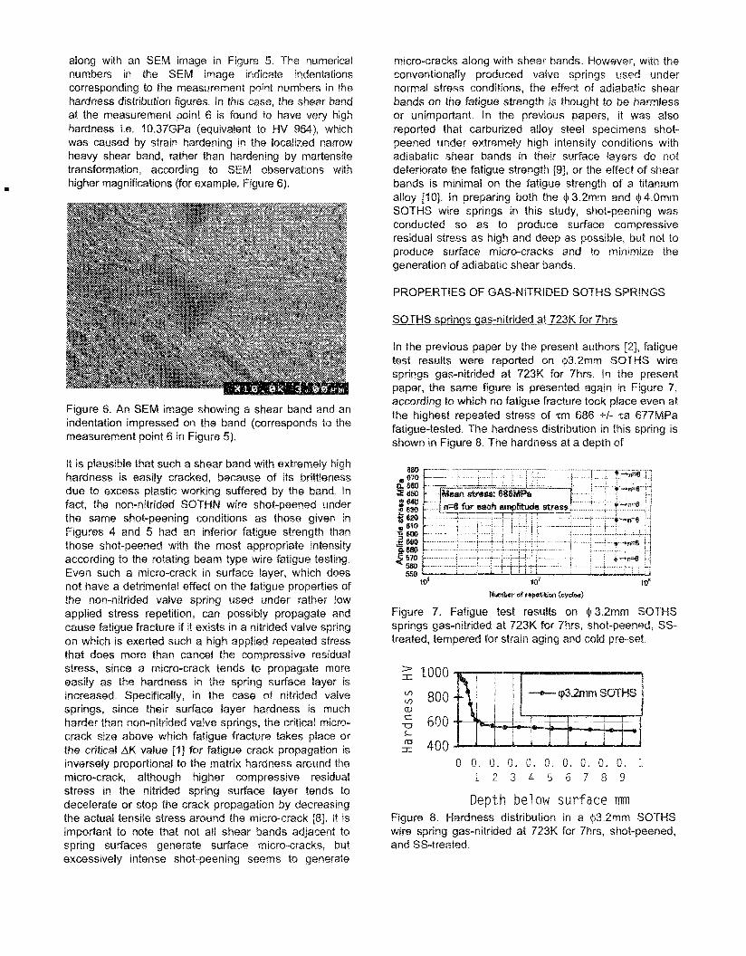
In the previous paper by the present authors 121, fatigue test results were reported on 43.2mm SOTHS wire springs gas-nitrided at 723K for 7hrs. In the present paper, the same figure is presented again in Figure 7, according to which no fatigue fracture took place even at the highest repeated stress of .tm 686 +I- %a 677MPa fatigue-tested. The hardness distribstion in this spring is shown in Figure 8. The hardness at a depth of
Figure 7. Fatigue test results on Q3.2mm SOTCIS springs gas-nilrided at 723K for 7hrs, shot-peened, SS- treated, tempered for strain aging and cold pre-set.
$ eooo : so0 w
600 L
400
Depth below sur face rnrn Figure 8. Hardness distribution in a Q3.2mm SOTHS wire spring gas-nitrided at 723K for 7hrs, shot-peened, and SS-treated.

0.97mm below the surface is HV524, which is lower than the hardness HV550 obtained ah a depth of 1.OSmm below the surface in the $4mm SOWS wire springs nitrided at 703K for 3hrs (Figure 2). The residual stress distribution measured for the $ 3.2mm SOTHS wire gas- nitrided springs is shown in Figure 9, The data in Figure 9 were obtained for the Q,3.2mm SQTHS wire gas- nitrided spring as SS-treated and non strain-aged. The sharp rise in compressive residual stress in the vicinity of the spring surface was caused by the SS-Treatment,
I
After tempeing a Q, 3.2mrn SOTHS nitrided, shot-peened and SS-treated spring at 493K for 20min, the outermost surface compressive residual stress measured was decreased to around f,GOOMPa from 2,035MPa (figure 9) obtained for an as-SS-ireated spring.
Depth below surface mm Figure 9. Residuat stress distribution in a gas-nitrided p 3.2mm SOTHS wire spring as-SS-treated. The nitriding condition: 72JK fcir Shrs
Mmm SWHS wire springs gas-nitrided at TO3K far 3hrs
It is recognizabie that the Qtmm SOTHS wife gas- nifrided spring has a lower surface layer hardness (Figure 2) than that of the 3.2mm SOTWS wire gas- nitrided spring (Figure %). This difference In surface layer hardness between them was primarily mused by the differing nitrogen contents in the nitrided layer owing
Depth below surface mm Figwe 10. Residual stress distribution in I$ 4mm SOXWS wire gas-nitrided spring
to the differing nitriding conditions. Figure 10 shows the residua! stress distribution in the surdace layer in the (I 4mm SOTHS wire spring which was nitrided at 303K
for 3hrs, shot-peened, SS-treated, tempered at 49% for 2Omin, and then cold pre-set. The compressive residua[ stress of 1,700MPa in the outermost surface layer in this spring is noted to be smaller than that of 2,035MPa obtained for the (I3.2rnm SQTHS spring piotted in Figure 9 but larger than that tempered for strain aging at 493K for ZOmin. The residual stress distribution at. the outermost surface layer are considered to be influenced by various factors: First, higher nittiding temperature and Bonger nitriding lime bath increase the surface compressive residual stress, semnd, shot-peening condition aiso affects it, and third, tempering for strain aging after shot-peening decreases the surface compressive residual stress. The Q,3.2mm SOTHS spring of which residual stresses were plotted in Figure 9 was nitrided at a higher temperature and for a longer time but shot-peened fess intense than the $4.Omm SOTHS wire nitrided spring, and not tempered after the SS-Treatment. The Q, 3.Zmm nitrided springs non- tempered far strain aging at 493M for 20rnin, also did not fatigue fracture at all (tested spring numbers n=6) undes the stress repetition at 686 +l- 677MPa until to the 5X10⁷ stress cycles, probably because of very high compressive residual stress in the surface layer. This seems to suggest that the tempering for strain aging at around 500K for the SS treated nitrided springs daes not deteriorate the fatigue life or strength, probably because the decreased compressive residual stress in the spring surface layer is compensated by the stronger dislocation locking in sx iron by enriched nitrogen atoms in salid solufion, which is expected to prevent slip band formation that causes micra-crack generation under tensile stress. In Table 4, the surface roughness measured by a surface measuring instrument with a stylus on the spring inside surface, is presented. All the fatigue tests were conducted under a mean stress 'tm= 736MPa at roam temperature. Fatigue test results for the p4mm SQTHS wire gas-nitrided springs are plotted in Figure 11. In the fatigue test candbrcted at the amplitude stress ~a=726MPa, ail four springs fatigue- fractured from their surface, IP the fatigue test at the amplitude stress 'ta=TOGMPa, a spring fractured starting from a sub-surface non-metallic inclusion at 1.5X10i cycles, other two springs fractured starting from their surface at 1.5X10⁷ cycles and at 3.OX1O7cyc!es respectively, and the remaining three springs did not fracture until 5X10⁷ cycles. At the lowest amplitude stress fatigue-tested, i.e,, za=667MPa, no spring fracture took place among 6 springs fatigue-tested. From these resub, the fatigue Eimit stress at 5x10'
Table 4. Surface roughness of a Wrnm SOTHS gas- nitrided spring (Mean vaiue from six measurements)

cycles is determined lo be 73SMPa +I.- S87MPa, according to the method (b) in S.Ii(2) in JIS 22273 "General rules for fatigue testing of metals", by which rule, fatigue limit ampiitude stress is determined as the mean value of the maximum amplitude stress where no fatigue fracture took place and the lowest amplitude stress where at least one specimen fatigue fractured. In order to sdatisticaily determine fatigue limit stress at SX~07cycles of stress repetition, analysis of fatigue data by the Probit method was also made. As a result, fatigue
3 limit stress was determined to be zm 736MPa +I- za 665MPa at p - 40, or 99.994% survival, where p is the mean amplitude stress and o is the standard deviation.
-_i
-10% 1 o6 I o7 .re Number of stress repetihon Cycles
Figure 11. Fatigue test results on 4mmSO'fHS wire springs gas-nitrided, shot-peened, SS-treabd, tempered and cold pre-set.
DISCUSSION
CAUSES OF HlGkl FATIGUE LIMIT STRESS OBTAINED
Factors to improve fatigue strerlat
There are many factors to be considered in obtaining very high fatigue strength in valive springs. Generally, in order to avoid fatigue fracture from sub-surface hard non-metallic inc[usions, it is necessary to add high compressive residual stress deep or high in the spring surface layer. In realizing this, improved shot-peening utilizing shot particles with a rather large diameter and/or higher hardness and in some cases gas-nitriding is applied in valve spring production. Figure 12 is a §EM image indicating the sub-surface fracture origin in ?he fish-eye pattern, taken on the fatigue fracture surface from a spring stressed at the amplitude stress za=706MPa and fractured at 1.5X10' cycles. The depth and the size of the non-metallic inclusion at the fracture origin were 0.35rnm and 30ym respectively. It seems to be important to recognize that the crossing point in residual stress distribution where the residual stress becomes zero (in the fatigue tested 4 4mm SOTHS wire gas-nitrided springs, it is around 0.23mm below the surface) is far deeper than the thickness of the nitrided
layer (in this study, it is around 80 vrn befow the surface as is shown in Figure I ) . The crossing point depth can be further increased by the imprctvemenl of nitrided spring production process though not reported in the present paper. To enhance compressive residual stress in the spring surface layer including from the surface to the crossing point, is another countermeasure to prevent fatigue fracture from sub-surface harmful nun-metallic incsusions and from surface micro-cracks 181 by stopping or decelerating fatigue crack prspagation there. Nitriding and the SS Treatment are exampies of such measures. Of course, it is also necessary to decrease the size and quantity of harmful non-metallic inclusions in steel making and solidification processes in steel mills.
Figure 12. SEM image showing fatigue fracture from a non-metallic inclusion. Specimen: $4mm SOTHS gas- nitrided spring fatigue fractured at the amplitude stress 706MPa and 1 .5X107 cycles. The length of the white bar in the image is 100pm.
It is also very important to avoid producing harmful defects such as surface micro-cracks or naichs in spring production processes, e.g. spring coiling and shat- peening. In the normal shot-peening process applied to non-niltrided springs, adiabatic shear band formation is known to occur frequentfy and its formation ~n the spring surface layer does not inversely affect the spring fatigue characteristics as far as their micro-crack size is smaller than a certain value. Even if shear band formation occurs in the surface layer by shot-peening, it may not be harmful in fatigue of the spring when no micro- crackfs) is (are) produced at the end(s) of the band. In this study, especiaiiy in preparing $4mm SOTHS wire gas-nitrided springs for fatigue testing, such adiabatic shear bands with micro-cracks were prevented by adjustment of the shot-peening conditions. According to the authors' experiences on the SS-treatment, it can be quite an excelfent process in that it can add high compressive residual stress in the surface layer without producing any micro-cracks caused by the SS- Treatment. The effect of the SS-Treatment on non- nitrided valve springs and on nitrided valve springs is considered firstly to prevent fatigue fracture from surface and secondly ia delay or stop the crack which has

progressed to the surface layer from a sub-surface inclusion as was already reported in previous papers [ I & 21.
STRESS RELAXATION
Factors to improve stress relaxation property
Chemical compositions in steel, especially carbon and silicon are known as eilements which improve resistance
I
to stress relaxation Vanadiirm is known to be an austenite grain size refiner and through refinement of prior austenite grain size can contribute to improved resistance to stress relaxation. It is also important not to hold so called retained austenite in a spring, which is caused by excessive amounts of al%oytng addition in steel, since it accelerates spring stress relaxation. in the SOTHS wire nitrided springs, no retained austenite remained according to an analysis by X-ray diffraction. The clamping test was conducted at 393M for 48hrs for a 4.0mm SOTHS wire gas-nitrided (at 703K for 3hrs) spring. The result is plotted in Figure 13. In this figure, the clamping test result obtained for the Q, 32mm SOTHS gas-nitrided spring is also plotted for comparison. When comparing these two springs, no big difference in stress relaxation is recognized between them, in spite of the higher core hardness in the Q,4.0mm SOTEIS gas-nitrided spring than the Q,3.2mm SOTWS gas-nitrided spring. The lower core hardness in the latter spring might be counter-balanced by the higher hardness, higher diffusibre nitrogen content in the surface layer in the latter compared with the former.
5 0 0 6 0 0 700 800 900 1 0 0 0 1100 1200
C l a i n p i v g shear ' stress MPa
Figure 13, Comparison of warm clamping test results between $.l.Omna SOTHS wire gas-niirided spring and Q, 3.2mm SOTHS wire gas-nitrided spring. Testing temperature and time: 393K and 48hrs.
Nitrogen in stecF has higher solid solubility in a iron than carbon and can anchor dislocations st room temperature and at around 393K, resulting in smaller relaxation caused by dislocation motion. Another impo&ni method to improve the resistance to stress relaxation is applying hot or warm pre-setting instead of appiying cotld pre- setting.
Tho stress relaxation properties of springs gas- nitrided at 703K for 3hrs, made from three kinds of valve spring quality wires (SOTHS, SOTHN, and JIS SWBSC-V) were compared. It was found that the SOTHS wire spring gave the best resistance to stress relaxation. The J1S SWBSC-V (SAE9254) had the wowt resistance to it.
The core hardness after the gas-nitriding was the highest in the SOTb-IS wire springs and the lowest in the JIS SWOSC-V spring.
The nitrided layer thickness of the three grades of wire springs gas-nitrided at 703K for 3hr, was found to be approximately 80 pm in each case.
The depth of the compressive residual stress layer below the gas-nitrided spring surface (=depth to crossing point) after shot-peening was found to be more than 150 ym, indicating the depth to crossing point was increased by shot-peening condition.
By the SS-Treatment applied after conventional shot-peening for tho SOTHS wire gas-nitrided springs, compressive residual stress as high as 1,700 (for Q, -4mm spring) to 2,035MPa (for Q, 3.2mm spring) was obtained at the spring surface.
The fatigue limit strength at 5X"i7 cycles obtained for the Q, 4mm SOTMS wire gas-nitrided springs was 7m 736MPa */- ~a687MPa from the S-N curve and when the fatigue life data were staiis'ticaiiy treated, it was ~ m 7 3 6 +!- za 665MPa.
Y. Yamada, I. Saitoh, NI. Ishida, K. Uzumaki, H. Suzuki and K. Teratoko: Improved Fatigue Strength of Valve Sprmgs and Sheet Springs by Application of a New Fine Shot Peening Technology, SAE Technical Paper Series 2000-01-0791. Y. Yamada, M. Teratoko, T. Saitoh, H. Sasada and T. Yanagihara: Improvement of Fatigue Strength of Niitrided High-Strength Valve Springs by Application of a New Super Fine Shot-Peening 'Technology. SAE TechnicaD Paper Series 2001-01-Q834 / SAE Transactions, Section 5 - Voi. 120, (2001), p.729- 737 Fa. H. Gassner: Demrburization and its evaluation by the chord method, Metal Progress, March (19781, 59 J Hey 0: Mechanical Testing by Indentation, Cauwe Motes (1997), Nano Instruments inc. Y. Oki, N. ibaraki, T. Kuroda, D. Ogura and N. Voshihara: High strength valve spring steel with excellent fatigue life? Wire Journal internatianai, V01.34, No.4 (2001) p.202-207

6. S. P. Timothy: The structure of adiabatic shear bands in metals: A critical review, Acta metall., V0l.35, NO, 2, (2987) p. 301-306,
7. C. L. Wittman, M. A. Meyers, and H-r. Pak: Observation of an adiabatic shear band in RIS! 4340 steel by high-voltage transmission electron microscopy, Metail. Trans. A, Vol. 2114, March (1990) p. 707-716
8. H. Saloh, Y, Kawaguchi, M, Nakamura, T. Kobayashi and Y. Isono: Influence of sutface Raw on
1 fatigue life 005 valve springs, Wire Jsur'nat International, March (1 995), p. 120-1 25
9. S. Adachi: Fatigue strength of gear steels shot peened in extremely high intensity conditions, Proceedings of the 4'h International Conference on Shot Peening, edited by K. Ikeda, J.S.P.A. (2990) p.363-372
10. S. P. Timothy and M. Hutchings: Influence of adiabatic shear bands on the fatigue strength of a titanium alloy, Fatigue Engrng Mater. Struct. Vol. 7, NO. 3 (1984) p.223-227
CONTACT
Yoshiro Yamada is Dr. Eng, lice17ced professional engineer, in metal field, Japan, and technical advisor for Suncall Gorp. His e-mail address is: [email protected]
Keiichiro Teratoko is the chief engineer in Toyota Pfant, Suncall Corp. His e-mail address is terak@lilac,ocn.ne.jp
Tadashi Saitoh is Senior executive officer, Suncall Corp. His e-mail address is [email protected]