Embed Size (px)
Citation preview

Mot
herb
oard
P4U800-X

2
T1448
© 2004

3

4

5

6
•
•
•
•
•
•
•
•
•
•
•
•

7
•
•
•

8
P4U800-X-TAYZ
10839 110366 0
11XX11XX11
™
Jumper Free(Default)
2 3
Jumper Mode
1 2

9
® ®
®
®

10

1-1

1-2
®
®
®
®

1-3

1-4
P4U800-X
®
P4U800-X Onboard LED
SB_PWR
ONStandbyPower
OFFPowered
Off

1-5
PANEL
P4U800-X
®
AUXCD
CPU_FAN1
FP_AUDIO
USB2.0
GAME1
Socket 478
ATX12V1
CHASSIS1
CLRTC
CHA_FAN1USB56
COM1
US
BP
W34
US
BP
W12
SB_PWR
USBPW56

1-6

1-7
®
®
P4U800-X
®
P4U800-X Socket 478
G

1-8
®
®
®
®
®
90 - 100

1-9
P4U800-X
®
P4U800-X 184-Pin DDR DIMM Sockets
80 P
ins
104
Pin
s
DIM
M1
DIM
M2
DIM
M3

1-10
256MB KINGSTON KVR400X64C3A/256 N/A Hynix SS HY5DU56822BT-D43 • •512MB KINGSTON KVR400X64C3A/512 N/A Hynix DS HY5DU56822BT-D43 • •256MB KINGSTON KVR400X64C3A/256 N/A Infineon SS HYB25D256800BT-5B • •512MB KINGSTON KVR400X64C3A/512 N/A Infineon DS HYB25D256809BT-5B •256MB KINGSTON KVR400X64C3A/256 N/A KINGSTON SS D3208DL2T-5 • •512MB KINGSTON KVR400X64C3A/512 N/A KINGSTON DS D328DIB-50 • •512MB KINGSTON KHX3200A/512 N/A N/A DS Heat-Sink Package •256MB SAMSUNG M368L3223ETM-CCC N/A SAMSUNG SS K4H560838E-TCCC •512MB SAMSUNG M368L6423ETM-CCC 3 SAMSUNG DS K4H560838E-TCCC •256MB SAMSUNG M368L3223FTN-CCC 3 SAMSUNG SS K4H560838F-TCCC • •256MB Hynix HYMD232646B8J-D43 AA 3 Hynix SS HY5DU56822BT-D43 • •512MB Hynix HYMD264646B8J-D43 AA N/A Hynix DS HY5DU56822BT-D43 • •256MB MICRON MT8VDDT3264AG-40BCB N/A MICRON SS MT46V32M8TG-5BC • •512MB MICRON MT16VDDT6464AG-40BCB N/A MICRON DS MT46V32M8TG-5BC • •256MB Infineon HYS64D32300GU-5-B 3 Infineon SS HYB25D256800BT-5B • •512MB Infineon HYS64D64320GU-5-B 3 Infineon DS HYB25D256800BT-5B • •256MB Infineon HYS64D32300HU-5-C 3 Infineon SS HYB25D256800CE-5C •256MB CORSAIR CMX256A-3200C2PT 2 Winbond SS W942508BH-5 •512MB CORSAIR CMX512-3200C2 2 Winbond DS Heat-Sink Package •512MB CORSAIR VS512MB400 2.5 VALUE seLecT DS VS32M8-5 • •

1-11
A B C D E F G H
1-12
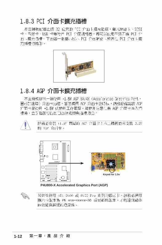
P4U800-X
®
P4U800-X Accelerated Graphics Port (AGP)
Keyed for 1.5v

1-13
P4U800-X
®
P4U800-X Clear RTC RAM
CLRTC
Normal Clear CMOS(Default)
32
12

1-14
P4U800-X
®
P4U800-X USB device wake up+5V
(Default)+5VSB
USBPW56
+5VSB
USBPW34
12
32
+5V(Default)
USBPW12
3221

1-15
1
11 8
4
5
6
7
2 3
910

1-16
P4U800-X
®
P4U800-X IDE connectors
SE
C_I
DE
1
PR
I_ID
E1
PIN 1
P4U800-X
®
P4U800-X Floppy disk drive connector
NOTE: Orient the red markings onthe floppy ribbon cable to PIN 1.
FLOPPY1PIN 1

1-17
P4U800-X
®
P4U800-X ATX power connectors
ATXPWR1 ATX12VPin 1
+3.3VDC-12.0VDCCOMPS_ON#
COMCOM
COM-5.0VDC+5.0VDC+5.0VDC
PWR_OK
+12.0VDC
+3.3VDC+3.3VDC
COM
+5.0VDCCOM
+5.0VDC
COM
+5VSB
+12V DCGND
+12V DCGND
P4U800-X
®
P4U800-X Internal audio connectors
AUX (White)CD (Black)
Rig
ht A
udio
Cha
nnel
Left
Aud
io C
hann
el
Gro
und
Gro
und
Rig
ht A
udio
Cha
nnel
Left
Aud
io C
hann
el
Gro
und
Gro
und

1-18
P4U800-X
®
P4U800-X Fan connectors
CPU_FAN1
CHA_FAN1
GN
D
Rot
atio
n+
12V
GN
D
Rot
atio
n+
12V
P4U800-X
®
P4U800-X USB 2.0 connector
USB56
US
B+
5VU
SB
_P8-
US
B_P
8+G
ND
NC
US
B+
5VU
SB
_P7-
US
B_P
7+G
ND
1

1-19
P4U800-X
®
P4U800-X Front panel audio xonnector
FP_AUDIO
BLINE_OUT_L
MIC2
Line out_R
Line out_L
BLINE_OUT_RNC
MICPWR +5VAAGND
P4U800-X
®
P4U800-X intrusion connector
CHASSIS1
+5V
SB
_MB
Cha
ssis
Sig
nal
GN
D
(Default)

1-20
P4U800-X
R
P4U800-X Game connector
GAME
+5V
+5V
J2B
1J2
CX
MID
I_O
UT
J2C
YJ2
B2
MID
I_IN
J1B
1J1
CX
GN
DG
ND
J1C
YJ1
B2
+5V
P4U800-X
®
P4U800-X System panel connector * Requires an ATX power supply.
PLE
D-
PW
R+
5V Spe
aker
SpeakerConnectorPower LED
Gro
und
Reset SW
Gro
und
Res
etG
roun
dG
roun
d
ATX PowerSwitch*
PLE
D+
IDE
_LE
D-
IDE
_LE
D+
IDE_LED
•

1-21
•
•
•
•

1-22

2-1

2-2

2-3

2-4
Bad BIOS checksum. Starting BIOS recovery...
Checking for floppy...
Floppy found!
Reading file “p4u800-x.bin”. Completed.
Start flashing...
Bad BIOS checksum. Starting BIOS recovery...
Checking for floppy...

2-5

2-6

2-7

2-8
•
•

2-9
<F1>
<F5>
<Esc>
← ← ← ← ← or → → → → → (keypad arrow)
↑↑↑↑↑ or ↓ ↓ ↓ ↓ ↓ (keypad arrows)
<PgDn> or - (minus key)
<PgUp> or + (plus key)
<Enter>
<F10>

2-10

2-11

2-12

2-13
IDE Primary Master
IDE Auto-Detection [Press Enter]
IDE Primary Master [Manual]Access Mode [CHS]
Capacity 40020 MB
Cylinder [19158]Head [ 16]Sector [ 255]Transfer Mode UDMA 2
F1 : Help ↑↑↑↑↑↓↓↓↓↓ : Select Item -/+ : Change Value F5 : Setup DefaultsESC : Exit →←→←→←→←→← : Select Menu Enter : Select Sub-menu F10 : Save and Exit
Select Menu
Item Specific Help
Enter the value.

2-14

2-15
CPU Type Intel Pentium(R) 4CPU Speed 2.40GHzCPU Cache RAM 512KCurrent FSB Frequency 533MHzCurrent DRAM Frequency 333MHzUSB Legacy Support [Enabled]USB 2.0 Controller [Enabled]Init Display First [PCI Slot]Frequency/Voltage ControlChip ConfigurationI/O Device ConfigurationPCI Configuration
F1 : Help ↑↑↑↑↑↓↓↓↓↓ : Select Item -/+ : Change Value F5 : Setup DefaultsESC : Exit →←→←→←→←→← : Select Menu Enter : Select Sub-menu F10 : Save and Exit
Select Menu
Item Specific Help

2-16
CPU Clock Ratio [17 X] CPU/MEM Clock Selectable [Auto]x CPU Clock Setting [100]x MEM Clock Setting [DDR266] Spread Spectrum [+/- 0.7%]
Frequency/Voltage Control
F1 : Help ↑↑↑↑↑↓↓↓↓↓ : Select Item -/+ : Change Value F5 : Setup DefaultsESC : Exit →←→←→←→←→← : Select Menu Enter : Select Sub-menu F10 : Save and Exit
Select Menu
Item Specific Help
Sets the ratio betweenCPU core clock andthe FSB frequency.

2-17
F1 : Help ↑↑↑↑↑↓↓↓↓↓ : Select Item -/+ : Change Value F5 : Setup DefaultsESC : Exit →←→←→←→←→← : Select Menu Enter : Select Sub-menu F10 : Save and Exit
Select Menu
Item Specific Help
Set the latencybetween the DRAMcommand and the timethe data actuallybecomes available.
Chip Configuration
CAS Read Latency [Auto (By SPD)]Current CAS Latency 2.5DRAM Performance [Auto (By SPD)]
x DRAM Timing tRP 3T x DRAM Timing tRAS 6T x DRAM Timing tRCD 3T
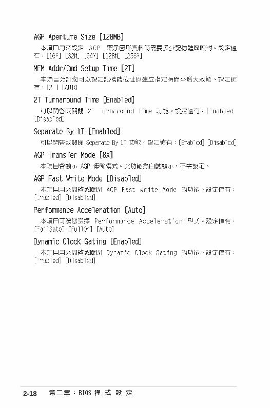
AGP Aperture Size [128MB]MEM Addr/Cmd Setup Time [2T]2T Turnaround Time [Enabled]Separate By 1T [Enabled]AGP Transfer Mode 8XAGP Fast Write Mode [Disabled]Performance Acceleration [Auto]Dynamic Clock Gating [Enabled]
2-18

2-19
Onboard Serial Port 1 [3F8/IRQ4] Onboard Parallel Port [378/IRQ7] Parallel Port Mode [SPP]x ECP Mode USE DMA 3 EPP Mode Select [EPP1.7] Onboard AC97 Audio [Enabled] Onboard LAN [Enabled] Game Port Address [201] MIDI Port Address [330] MIDI Port IRQ [5]
I/O Device Configuration
F1 : Help ↑↑↑↑↑↓↓↓↓↓ : Select Item -/+ : Change Value F5 : Setup DefaultsESC : Exit →←→←→←→←→← : Select Menu Enter : Select Sub-menu F10 : Save and Exit
Select Menu
Item Specific Help
Press [Enter] to selectthe I/O address & IRQfor COM1.

2-20
Onboard LAN Boot ROM [Disabled]
Resources Controlled By [Auto (ESCD)]x IRQ Resources
PCI/CGA Palette Snoop [Disabled] Assign IRQ for VGA [Enabled] Assign IRQ for USB [Enabled] PCI Latency Timer (CLK) [ 64] PCI IRQ Actived By [Level]
PCI Configuration
F1 : Help ↑↑↑↑↑↓↓↓↓↓ : Select Item -/+ : Change Value F5 : Setup DefaultsESC : Exit →←→←→←→←→← : Select Menu Enter : Select Sub-menu F10 : Save and Exit
Select Menu
Item Specific Help
Enable/Disable theonboard SATA.

2-21
IRQ Resources
IRQ-3 assigned to [PCI Device]IRQ-4 assigned to [PCI Device]IRQ-7 assigned to [PCI Device]IRQ-9 assigned to [PCI Device]IRQ-10 assigned to [PCI Device]IRQ-11 assigned to [PCI Device]IRQ-12 assigned to [PCI Device]IRQ-14 assigned to [PCI Device]IRQ-15 assigned to [PCI Device]
IRQ Resources
F1 : Help ↑↑↑↑↑↓↓↓↓↓ : Select Item -/+ : Change Value F5 : Setup DefaultsESC : Exit →←→←→←→←→← : Select Menu Enter : Select Sub-menu F10 : Save and Exit
Select Menu
Item Specific Help
Legacy ISA for devicescompliant with theoriginal PC AT busspecification, PCI/ISAPnP for devicescompliant with the Plugand Play standardwhether designed for PCIor ISA bus architecture.

2-22
Select Menu
Item Specific Help
Select the ACPI stateused for System Suspend.
F1 : Help ↑↑↑↑↑↓↓↓↓↓ : Select Item -/+ : Change Value F5 : Setup DefaultsESC : Exit →←→←→←→←→← : Select Menu Enter : Select Sub-menu F10 : Save and Exit
ACPI Suspend Type [S1&S3]Suspend Mode [Disabled]AC Power Loss Restart [Disabled]
Power Up ControlHardware Monitor

2-23
Power Up On PCI Devices [Disabled] Power Up By PS/2 Keyboard [Disabled] Power Up By PS/2 Mouse [Disabled] Power Up by Onboard LAN [Disabled] RTC Alarm Resume [Disabled]x Date (of Month) 0x Resume Time (hh:mm:ss) 0 : 0 : 0 PWR Button <4 secs [Instant-Off]
Power Up Control
F1 : Help ↑↑↑↑↑↓↓↓↓↓ : Select Item -/+ : Change Value F5 : Setup DefaultsESC : Exit →←→←→←→←→← : Select Menu Enter : Select Sub-menu F10 : Save and Exit
Select Menu
Item Specific Help
Press [Enter] to select.

2-24

2-25
Hardware Monitor
F1 : Help ↑↑↑↑↑↓↓↓↓↓ : Select Item -/+ : Change Value F5 : Setup DefaultsESC : Exit →←→←→←→←→← : Select Menu Enter : Select Sub-menu F10 : Save and Exit
Select Menu
Item Specific Help
Press [Enter] to enableor disable.
CPU Temperature 47°CMB Temperature 45°C
CPU Fan Speed 5443RPMChassis Fan Speed 0RPM
VCore 1.79V+ 3.3V 3.37V+ 5V 4.94V+ 12V 11.36V

2-26
Select Menu
Item Specific Help
Select your boot devicepriority.
F1 : Help ↑↑↑↑↑↓↓↓↓↓ : Select Item -/+ : Change Value F5 : Setup DefaultsESC : Exit →←→←→←→←→← : Select Menu Enter : Select Sub-menu F10 : Save and Exit
First Boot Device [HDD-0]Second Boot Device [CDROM]Third Boot Device [Floppy]Fourth Boot Device [Disabled]Plug & Play OS [Yes]Reset Configuration Data [Disabled]Quick Power On Self Test [Enabled]Boot Up Floppy Seek [Disabled]Boot Up NumLock Status [On]APIC Mode [Enabled]

2-27

2-28
Select Menu
Item Specific Help
This option saves datato CMOS and exits theBIOS Setup.
F1 : Help ↑↑↑↑↑↓↓↓↓↓ : Select Item -/+ : Change Value F5 : Setup DefaultsESC : Exit →←→←→←→←→← : Select Menu Enter : Select Sub-menu F10 : Save and Exit
Save & ExitExit Without SavingLoad SETUP DefaultsDiscard ChangesSave Changes

3-1

3-2

3-3

3-4