Embed Size (px)
Citation preview

PERFORM WITH PRECISION
DELTA TIE
INSULATED CONCRETE SANDWICH PANEL TIE
APPLICATION GUIDE

INNOVATIONCENTER
REAL-WORLD SOLUTIONS
INSPIRED BY YOUR VISION
Your vision is to take concrete construction to new heights.
We turn that vision into real-world solutions through
precision research and development, testing and technology.
Together we are redeining what is possible in the
concrete construction industry. Our Innovation Center
is comprised of:
• A state of the art chemical lab
• A full-featured mechanical test facility
• Product demonstration areas
• Contemporary training and meeting areas
Bring us your ideas and we will deliver your solution.
Call today: 888-977-9600 Perform with Precision™
®
®
Delta Tie Application Guide
1 877-266-773205/16 | PERFORM WITH PRECISION™
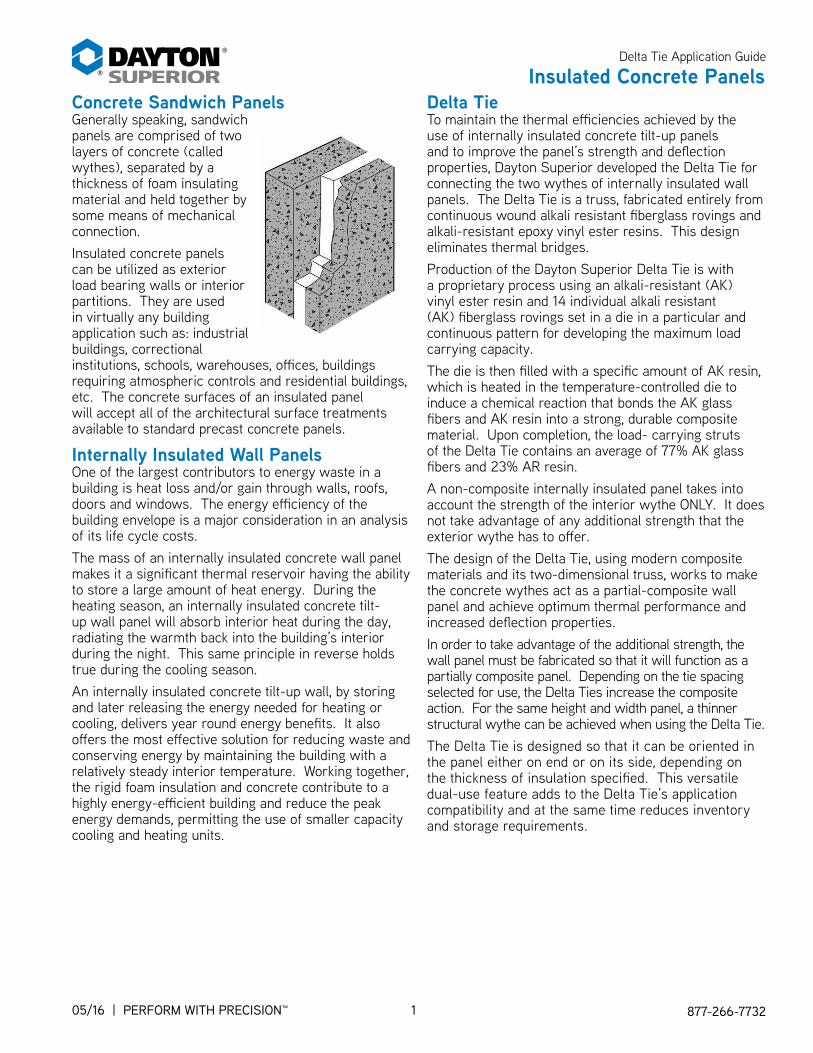
Concrete Sandwich PanelsGenerally speaking, sandwich panels are comprised of two layers of concrete (called wythes), separated by a thickness of foam insulating material and held together by some means of mechanical connection.
Insulated concrete panels can be utilized as exterior load bearing walls or interior partitions. They are used in virtually any building application such as: industrial buildings, correctional institutions, schools, warehouses, oices, buildings requiring atmospheric controls and residential buildings, etc. The concrete surfaces of an insulated panel will accept all of the architectural surface treatments available to standard precast concrete panels.
Internally Insulated Wall PanelsOne of the largest contributors to energy waste in a building is heat loss and/or gain through walls, roofs, doors and windows. The energy eiciency of the building envelope is a major consideration in an analysis of its life cycle costs.
The mass of an internally insulated concrete wall panel makes it a signiicant thermal reservoir having the ability to store a large amount of heat energy. During the heating season, an internally insulated concrete tilt-up wall panel will absorb interior heat during the day, radiating the warmth back into the building’s interior during the night. This same principle in reverse holds true during the cooling season.
An internally insulated concrete tilt-up wall, by storing and later releasing the energy needed for heating or cooling, delivers year round energy beneits. It also ofers the most efective solution for reducing waste and conserving energy by maintaining the building with a relatively steady interior temperature. Working together, the rigid foam insulation and concrete contribute to a highly energy-eicient building and reduce the peak energy demands, permitting the use of smaller capacity cooling and heating units.
Insulated Concrete PanelsDelta TieTo maintain the thermal eiciencies achieved by the use of internally insulated concrete tilt-up panels and to improve the panel’s strength and delection properties, Dayton Superior developed the Delta Tie for connecting the two wythes of internally insulated wall panels. The Delta Tie is a truss, fabricated entirely from continuous wound alkali resistant iberglass rovings and alkali-resistant epoxy vinyl ester resins. This design eliminates thermal bridges.
Production of the Dayton Superior Delta Tie is with a proprietary process using an alkali-resistant (AK) vinyl ester resin and 14 individual alkali resistant (AK) iberglass rovings set in a die in a particular and continuous pattern for developing the maximum load carrying capacity.
The die is then illed with a speciic amount of AK resin, which is heated in the temperature-controlled die to induce a chemical reaction that bonds the AK glass ibers and AK resin into a strong, durable composite material. Upon completion, the load- carrying struts of the Delta Tie contains an average of 77% AK glass ibers and 23% AR resin.
A non-composite internally insulated panel takes into account the strength of the interior wythe ONLY. It does not take advantage of any additional strength that the exterior wythe has to ofer.
The design of the Delta Tie, using modern composite materials and its two-dimensional truss, works to make the concrete wythes act as a partial-composite wall panel and achieve optimum thermal performance and increased delection properties.
In order to take advantage of the additional strength, the wall panel must be fabricated so that it will function as a partially composite panel. Depending on the tie spacing selected for use, the Delta Ties increase the composite action. For the same height and width panel, a thinner structural wythe can be achieved when using the Delta Tie.
The Delta Tie is designed so that it can be oriented in the panel either on end or on its side, depending on the thickness of insulation speciied. This versatile dual-use feature adds to the Delta Tie’s application compatibility and at the same time reduces inventory and storage requirements.

®
®Delta Tie Application Guide
2WWW.DAYTONSUPERIOR.COM PERFORM WITH PRECISION™ | 05/16
Delta Tie Design AdvantagesDelta Tie AdvantagesThe Delta Tie has exhibited excellent loading behavior and load capacities in tests conducted on individual test specimens as well as in full-scale panel tests.
The Dayton Superior Delta Tie ofers the owner, speciier and contractor the following advantages:
Use With Any Rigid Foam InsulationThe Delta Tie can be used with any locally available type or brand of rigid foam insulation.
Easy Learning Curve Users have reported that it takes just a short length of time to get their employees “up to speed” on installing the Delta Tie.
Labor SavingsUsers have reported up to a 50% increase in labor savings, due to having to install fewer ties.
Less Expensive DesignThe Dayton Superior P24 Delta Tie uses up to 75% fewer ties versus comparable systems.
Design FlexibilityThe capabilities of the Delta Tie’s truss design greatly in-creases the stifness of the panel.
Partial Composite ActionDue to the composite action that can be gained by using the Delta Tie, thinner panels can be designed, braced and erected.
No Thermal BridgesInsulation is not interrupted by block-outs for connectors, allowing for insulation to be placed from panel edge to panel edge and from top of panel to bottom of panel.
Increased Composite Moment of InertiaDepending on the selected tie spacing, the composite moment of inertia of the tilt-up panel can be increased, which can result in a thinner overall panel thickness.
Tested PerformancePassed ASTME-119 (4 hour) and NFPA 285 ire testing
Tensile StrengthBased on results from tensile testing, the P24 Delta Tie has an average ultimate tensile capacity of over 3,100 lbs. per tie, in its narrow orientation and in excess of 3,400 lbs. per tie in its wide orientation.
In a typical panel, the Delta Ties may be subjected to approximately 500 lbs. of tensile force during the erection process. Assuming a 3" exterior wythe, that force can be calculated as follows:
Face Weight (150 pcf normal weight concrete) = 37.5 psf Suction = 25 psf Total = 62.5 psf Tributary area per Delta Tie = 8.0 sq.ft. Tensile force per Delta Tie = 500 lbs.
The P24 Delta Tie has an average ultimate shear capacity of approximately 3,200 lbs. per tie, regardless of its orientation – narrow or wide installation.
In a typical panel, the Delta Ties will be subjected to approximately 300 lbs. of shear force during the erection process. Again, assuming a 3" exterior wythe, that force can be calculated as follows:
Face Weight (150 pcf normal weight concrete) = 37.5 psf Tributary area per Delta Tie = 8.0 sq.ft. Tensile force per Delta Tie = 300 lbs.
Even though it appears that the tie spacing could be increased, Dayton Superior does not recommend it. The maximum recommended tributary area for either tensile or shear loading conditions is 8.0 sq.ft. per tie.
Note: When composite action is not required, maximum tie spacing for a 3"-2"-3" (76mm-50mm-76mm) panel is 8 sq.ft. (0.74 M2) per tie. Test reports are available on request.

®
®
Delta Tie Application Guide
3 877-266-773205/16 | PERFORM WITH PRECISION™
Insulation MaterialsAlthough insulation can be made from a variety of materials, it usually comes in ive typical forms: blankets, blown-in, loose-ill, relective ilm or rigid foam board. Each type of insulation is made to work in a particular part of a building. Closed-cell foams, such as polystyrene, in which the air is trapped in bubbles is an excellent insulator and are generally using for internally insulating concrete tilt-up wall panels.
The Dayton Superior P24 Delta Tie is designed for use with any of the rigid foam insulation materials presently on the market. The speciier is not tied into using only one type or brand of foam insulation – use the type and brand that is most readily available meeting the project’s speciied R-value. The thickness of insulation needed depends on the climate, type of heating used and building use.
The following four types of rigid foam insulation, having initial R-values ranging from R-4 to R-8 per inch of thickness, are used in internally insulated tilt-up wall panels:
• MEPS (molded expanded polystyrene)• XEPS (extruded polystyrene)• PUR (polyurethane)• PIR (polyisocyanurate)
MEPS insulation will bond to the concrete and is often referred to as “bead board.” When used in an internally insulated panel, it must have suicient density so that workers can walk on it without causing any damage. MEPS foam is susceptible to absorbing moisture resulting in a reduced R-value. A plastic vapor retarder should be considered when using this type of insulation.
XEPS foam is a closed-cell material that is more consistent in density, does not bond to concrete and has a higher compressive strength. It also has a reputation for long-term reliability and superior resistance to time, water, cold, heat, and pressure.
Both the PUR and PIR foams are closed-cell foams that contain a low conductivity gas in their cells. The thermal resistance of the gas gives these foams a higher R-value than either MEPS or XEPS foams. However, due to a phenomenon known as “thermal drift,” the R-value of these two foams drops over time as the insulation ages and some of the gas escapes and is replaced by air.
Dayton Superior Insulated Concrete Panel TieThe Dayton Superior P24 Delta Ties are unique in concept and design. This versatile tie allows insulation from panel-edge to panel-edge eliminating thermal bridges and costly energy loss. The Delta Tie is a non-metallic, geometrically configured, two-dimensional truss manufactured from continuous wound fiberglass embedded in an alkali resistant resin. The non-metallic design of the Delta Tie eliminates thermal transfer through the panel, increasing the insulating efficiency.
The P24 and P24XL Delta Tie dimensions are shown in the accompanying detail. Other sizes are available on special order.
The tie is designed so that it can be oriented in the panel either on end or side depending on the thickness of the panel. For example, the 5" x 7" (127mm x 178mm) size can be used on its side in a six inch (15mm) panel or on end for thicker panels. This versatile, dual-use feature adds to the Delta Tie’s efective application compatibility and, at the same time, reduces inventory and storage requirements.
In individual tie specimen and full size panel tests, the Delta Tie has exhibited excellent loading behavior and load capacities.
Patent Number 2316238
Patent Number 6761007
Product Code
Size
1241075” X 7”
Tie
1439849” X 11”
Tie

®
®Delta Tie Application Guide
4WWW.DAYTONSUPERIOR.COM PERFORM WITH PRECISION™ | 05/16
Materials and ComponentsInsulated Panel ComponentsInternally insulated wall panels are made up of three diferent wythes:
• The EXTERIOR WYTHE acts as a barrier against the environment, protecting the foam insulation from exterior damage, and depending on design requirements and architectural treatments, may be as thin as 2". It can have any architectural treatment, such as those created with formliners, an exposed aggregate surface, a thin brick surface or a simple textured coating.
• The foam INSULATION provides an excellent thermal barrier that works to reduce heat loss as well as the building’s energy costs.
• The INTERIOR WYTHE is normally the structural wythe, which supports the wind, roof, as well as any upper loor loads. It also protects the insulation from damage. Depending on the spacing of the Delta Tie, the interior wythe can work with the exterior wythe providing partial composite action for the wall panel. Having the thicker or structural wythe on the interior side of the building also acts to maximize the thermal efect of the wall by stabilizing the interior temperature, resulting in lower energy costs.
Concrete, because of its density, has the capacity to absorb and store large quantities of heat. This thermal efect causes concrete to react very slowly to changes in outside temperature. This characteristic reduces peak heating and cooling loads and delays the time at which these peak loads occur. This delay improves the performance of heating and cooling equipment, since the peak cooling loads are delayed until nighttime, when the outside temperature has dropped.
Delta Ties inserted into the irst wythe — the exterior wythe — along the edge of the second wythe — the rigid insulation.
The third wythe — the interior wythe — being installed over the insulation, incorporating the Delta Tie and rebar.

®
®
Delta Tie Application Guide
5 877-266-773205/16 | PERFORM WITH PRECISION™
Insulated Wall R-ValuesInternally insulated concrete walls are designed to resist the low of heat energy through the wall. In most buildings, internally insulated walls are used to keep the heat inside the building. However, in special cases, such as a freezer application, internally insulated walls are designed to keep cold in and heat out.
R-value is a rating or measure of resistance of an insulation’s ability to retard the low of heat. Generally, the higher the R-value, the better insulator it is. Foam insulation’s long-term R-value will vary depending upon the characteristics of its manufacture. It is suggested that the speciier consult the insulation manufacturer for this information.
Insulated Wall U-ValuesAnother measure of how well a material or a combination of materials conducts heat is the U-factor, which is the reciprocal of the R-value. The lower the U-factor, the better.
Internally insulated tilt-up concrete wall panels, with their high thermal storage properties, have an advantage over many other building materials. However, a solid concrete tilt-up wall, by itself, is not very efective as an insulator. For example, a 6" solid concrete wall has an R-value of 1.88 and a U-factor of 0.5319. By adding only 1" of extruded foam insulation to the middle of the 6" wall, the R-value of the wall will increase to 6.58 and the U-factor will drop to 0.1519.
The use of internally insulated walls having higher R-value would seem to be more eicient. However, the U-factor is a better number for use in determining the efectiveness of an insulated wall. As additional insulation is added to the wall, the wall’s R-value continues to increase at a uniform rate, but the U-factor drops more slowly as more insulation is added. The following chart illustrates this principle.
Exterior Wythe
Extruded Polystyrene Insulation
Interior Wythe
Total Wall Thickness
R-Value U-Factor
2-1/2" 1" 2" 5-1/2" 5.91 0.1692
2-1/2" 1-1/2" 2" 6" 8.26 0.1211
2-1/2" 2" 2" 6-1/2" 10.61 0.0943
2-1/2" 3" 2" 7-1/2" 15.31 0.0653
2-1/2" 4" 2" 8-1/2" 20.01 0.0500
2-1/2" 5" 2" 9-1/2" 24.71 0.0405
2-1/2" 6" 2" 10-1/2" 29.41 0.0340
2-1/2" 7" 2" 11-1/2" 34.11 0.0293
2-1/2" 8" 2" 12-1/2" 38.81 0.0258
2-1/2" 1" 3" 6-1/2" 5.95 0.1681
2-1/2" 1-1/2" 3" 7" 8.30 0.1205
2-1/2" 2" 3" 7-1/2" 10.65 0.0939
2-1/2" 3" 3" 8-1/2" 15.35 0.0651
2-1/2" 4" 3" 9-1/2" 20.05 0.0499
2-1/2" 5" 3" 10-1/2" 24.75 0.0404
2-1/2" 6" 3" 11-1/2" 29.45 0.0340
2-1/2" 7" 3" 12-1/2" 34.15 0.0293
2-1/2" 8" 3" 13-1/2" 38.85 0.0257
2-1/2" 1" 4" 7-1/2" 6.03 0.1658
2-1/2" 1-1/2" 4" 8" 8.38 0.1193
2-1/2" 2" 4" 8-1/2" 10.73 0.0932
2-1/2" 3" 4" 9-1/2" 15.43 0.0648
2-1/2" 4" 4" 10-1/2" 20.13 0.0497
2-1/2" 5" 4" 11-1/2" 24.83 0.0403
2-1/2" 6" 4" 12-1/2" 29.53 0.0339
2-1/2" 7" 4" 13-1/2" 34.23 0.0292
2-1/2" 8" 4" 14-1/2" 38.93 0.0257
2-1/2" 1" 6" 9-1/2" 6.23 0.1605
2-1/2" 1-1/2" 6" 10" 8.58 0.1166
2-1/2" 2" 6" 10-1/2" 10.93 0.0915
2-1/2" 3" 6" 11-1/2" 15.63 0.0640
2-1/2" 4" 6" 12-1/2" 20.33 0.0492
2-1/2" 5" 6" 13-1/2" 25.03 0.0400
2-1/2" 6" 6" 14-1/2" 29.73 0.0336
2-1/2" 7" 6" 15-1/2" 34.43 0.0290
2-1/2" 8" 6" 16-1/2" 39.13 0.0256
The total R-value of an internally insulated concrete wall panel is a summation of the individual items that make up the wall. The above chart is based on the following individual R-values.
• An R-value of 0.08 per inch of concrete.• An R-value of 4.7 per inch of insulation.• An R-value of 0.68 for the inside air ilm.• An R-value of 0.17 for the outside air ilm.
Insulation

®
®Delta Tie Application Guide
6WWW.DAYTONSUPERIOR.COM PERFORM WITH PRECISION™ | 05/16
Insulated Panels Provide Energy SavingsThermal Bridges/Cold SpotsThermal bridges are formed in internally insulated panels when concrete ribs and/or metal ties, which are used to connect the wythes together, interrupt the foam insulation layer.
Thermal bridges allow heat energy (thermal conductivity) to escape through the wall at a fast rate. Heat energy will always travel from a higher temperature to a lower temperature. The greater the diference in temperature, the faster the heat energy will travel.
When the transfer of heat energy occurs in a wall, it will create a cold spot. Cold spots are not only unsightly, they also allow condensation and freeze thaw areas to form. Thermal bridges will also lead to damage of the building’s walls and greatly reduce the insulating properties of the building.
To prevent the forming of concrete thermal bridges and/or iniltration of air, the rigid foam insulation should not be interrupted by block-outs for inserts or other embedment. The sheets should be placed tightly together with any gaps between the rigid foam sheets wider than 1/8", sealed with foam caulk or foam insulation sealing tape.
CondensationAs the insulation in any internally insulated tilt-up wall panel is subjected to a signiicant amount of moisture condensation, due to the insulation being enclosed in concrete, the “dew point” of the wall will usually occur inside the insulation layer. The “dew point” is a measure of the amount of moisture inside the wall. When metal ties are used to connect the wythes, the moisture hidden inside the wall will condense on the ties, causing the metal ties to fail due to corrosion (rust). When a suicient number of metal ties fail, the outer wythe will delaminate from the wall.
The non-metallic design of the Delta Tie is unique in both design and concept; allowing insulation to be installed from panel edge to panel edge which eliminates the formation of thermal bridges and their costly energy loss.

®
®
Delta Tie Application Guide
7 877-266-773205/16 | PERFORM WITH PRECISION™
Delta Tie DesignFor any given internally insulated concrete tilt-up panel, the load, shear and moment diagrams deine the required panel stifness for both the permanent in-place loads and the temporary loads imposed during the erection process.
By using the Delta Tie, the engineer is able to keep the thermal beneits of a fully insulated non-composite panel, yet increase the panel’s stifness. By selecting the appropriate Delta Tie spacing, a panel can now be designed having up to 50% of the moment capacity (composite action) of a solid, non-insulated panel. This design will allow both wythes to support a portion of the imposed loads, resulting in a stifer and stronger panel.
Delta Tie Design Chart
DisplacementThe results from one full-scale panel test show the load delection responses of the panel. All full-scale test panels exhibited a similar failure mode. After irst cracking, the load delection behavior was linear until the load at which the highly stressed Delta Ties begin to fail.
Load Capacities
Delta Tie Type
Insulation Thickness
Tension Capacity*
lbs
Shear Capacity*
lbs
P24 (5x7)
1 to 4 3100 3400
P24XL (9x11)
1 to 5 5800 3700
P24XL (9x11)
6 3400 3075
P24XL (9x11)
7 4000 2800
P24XL (9x11)
8 3200 1650
*Ultimate Strength Per Tie. Factor Of Safety is variable based on the panel coniguration.
Technical Information

®
®Delta Tie Application Guide
8WWW.DAYTONSUPERIOR.COM PERFORM WITH PRECISION™ | 05/16
Composite Moment CapacityFor any given sandwich panel the shear and moment diagrams deine the required panel stifness. The panel stifness may be altered as necessary pending panel parameters, by adjusting the tie distribution as a function of the internal shear and moment forces. The two examples below illustrate the required stifness (percent composite action) necessary to develop the shear and moment forces.
1. A panel measuring 37'-0" long by 6'-0" wide (11.28 meters x 1.83 meters) with a 3-2-3 (76-50-76) wythe pattern must have a 5% composite action to achieve a lat lift with 4x2 rigging.
2. A 2-2-2 (50-50-50) panel of same size requires a 20% composite action for the same rigging.
In order to employ the least amount of concrete to save weight, the percent of composite action must increase. A small upward adjustment can be realized by a minimal addition of ties strategically placed at the zones of maximum shear.
Engineering DetailsMinimum Wythe ThicknessA minimum external wythe thickness of 2" is recommended. If architectural features, such as reveals, a formliner or exposed aggregate, are present in the exterior wythe, then the minimum thickness would be 2" plus the thickness of the architectural feature.
EXAMPLE: For a wythe having a ¾" reveal, the minimum thickness would be ¾" + 2" or 2¾" minimum.
The structural wythe thickness will vary depend-ing on application of the panel (cladding or load bearing) and the imposed loads to which the panel will be subjected. The Engineer of Record for the building project must determine the actual wythe thickness.
Concrete/Reinforcing SteelNormally, a high quality, normal weight concrete having a minimum 28-day compressive strength of at least 4,000 psi is specified. Care should be taken when using self-consolidating concrete (SCC) in the thin exterior wythe, as workers must walk on top of the foam insulation during installation of the P24 Delta Ties and the SCC might not support the weight of the workers.
The concrete mix design for the exterior wythe should specify a maximum aggregate size of ¾". The use of a larger size aggregate will interfere with the installation of the Delta Tie.
The design-mix usually specifies a slump of between 4" and 6" out of the ready-mix truck at the jobsite.
The exterior and interior wythes should be reinforced per the American Concrete Institute’s Building Code Requirements for Structural, ACI 318 Latest Revision. Normally, #4 reinforcing bars spaced at 12" on centers each way and located in the center of the interior wythe will be sufficient.
The use of flat sheet welded wire fabric (mesh) is normally used in the exterior wythe.
0
2,000
4,000
Percent Composite
6,000
8,000
10,000
12,000
14,000
16,000
18,000
20,000
(276)
(553)
(829)
(1106)
(1382)
(1659)
(1936)
(2212)
(2489)
(2765)
60%50%40%30%20%10%0%
Chart based on 6'-0'' (1.83 Meters) Panel Width f'c = 5,000 psi (35 MPa)fba = 424 psi
Mo
men
t C
ap
aci
ty -
ft-
lbs
(kilo
gra
m-m
ete
rs)
3-2-3
2-2-2
P24XL
PATE
NT
#6761007
DSC
DELT
ATIE
0.15"
7"9"
9"11"
P24
DSC
DELT
A TIE
PATE
NT #6761007
0.118"
7"5"
5" 3"

®
®
Delta Tie Application Guide
9 877-266-773205/16 | PERFORM WITH PRECISION™
Installation InstructionsApplication Steps for Composite ActionStandard Installation1. After installing the required
exterior wythe’s welded wire fabric, place and screed the concrete to it specified thickness. Flat sheet mesh and concrete design mix using a superplasticizer admixture are recommended.
2. Cut the first strip of foam to 12" width and place it tightly against the side of the form.
3. Insert the first row of Delta Ties spaced vertically as required. If the tie hits the reinforcing mesh, prior to reaching its minimum embedment depth, move the tie slightly so that the reinforcing mesh sits in the depressed “V” section of the tie. NOTE: The minimum tie embedment into the fresh concrete shall be 1½".
4. Adding the remaining courses of insulation and connectors. Foam-back tape is available for sealing the insulation joints, if necessary.
5. When all of the foam sections and connectors have been placed, the top concrete wythe is poured and screeded as necessary.
6. After proper concrete set, the panel may be removed from the form and the process repeated.
Important Information:• It is critical that Steps #1
through #6 be completed immediately after the bottom wythe has been consolidated and leveled to its required thickness, no later than 15-20 minutes after placement of the concrete to ensure it is still plastic. If the Delta Tie is not embedded into the concrete while the concrete is still plastic, the concrete will not properly engage the Delta Tie.
• As the Delta Tie is a one-way shear connector, meaning it is stronger in one direction than it is in the other direction, care must be taken to make certain it is installed in its intended orientation in the panel.
• When using Dayton Superior Delta Ties, the lifting inserts and brace anchors are installed in the structural wythe ONLY, resulting in no thermal bridge.
Post Placement Inspection of Ties
• Usually done the next day• Check all ties for looseness
and placement• Identify any that require
retroitting
Delta Tie Retroit
1. Cut insulation around tie2. Use a quick cut saw to cut away old Delta Tie and
create a replacement slot 1-1/2" deep3. Clean out slot4. Fill slot with J58 Resi-Bond epoxy (follow J58
Technical Data Sheet instructions)5. Place new Delta Tie into slot6. Replace insulation around new tie
A simple setting block.
07/16 | PERFORM WITH PRECISION™

®
®Delta Tie Application Guide
10WWW.DAYTONSUPERIOR.COM PERFORM WITH PRECISION™ | 05/16
Delta Tie Design SoftwareThe Delta Tie design software technology provides a useful set of tools for both designers and fabricators. It provides quick answers to many of the common questions about Delta Tie applications in an insulated concrete panel.
The reliability of data from this technology has been validated by incorporating the results of numerous test programs directly into the program’s code.
Functions Primarily Intended For The Panel Designer:Details The Panel Construction• Wythe Thicknesses• Delta Tie Spacing and Type (P24, P24XL)• Concrete Mix Design• Insulation Properties
Determines The Resulting Panel Mechanical Characteristics• Area Density• Panel Weight• Center-of-Gravity• Tensile and Shear Factor of Safety• Composite Action % and Moment of Inertia• Bending Moments, Stresses, and Delection Estimates
Calculates The Panel Thermal Properties (Unmodiied Areas Only)• Composite R-Value• Heat Flux and Transfer Rate• Heat Delection• Fire Rating
Functions Primarily Intended For The Delta Tie Installer:Automatically Creates Layout Drawings• Provides a Drawn-To-Scale image of the Installation
- Details Tie Positioning for both views (End and Face)- Key Dimensions are labeled
• Marks the Center of Gravity and Dunnage Locations• Includes Delta Tie Bill-of-Materials• Displays A Uniied Panel Identiication On Each Printout
Deines Areas Where The Panel Construction Needs To Be Modiied• (Mitered Edges, Thickened Sections, etc.)• Documents the Location and Dimensions of each Area• Displays each area on the Layout Drawing• Positions Ties adjacent to modiied Area automatically and adjusts the Bill-of-Materials
The Delta Tie design software technology is available as a download: www.daytonsuperior.com/forms/delta-tie-request.

®
®
Delta Tie Application Guide
11 877-266-773205/16 | PERFORM WITH PRECISION™
Typical Construction Details
Walls
Corners
Roofs and Parapets
Tall Return Construction Sequence
Openings
4/16

®
®Delta Tie Application Guide
12WWW.DAYTONSUPERIOR.COM PERFORM WITH PRECISION™ | 05/16
Notes and Sketches

®
®
Improper Use of Concrete Accessories Can Cause Severe Injury or Death
Read, understand and follow the information and instructions in this publication before using any
of the Dayton Superior concrete accessories displayed herein. When in
doubt about the proper use or installation of any Dayton Superior concrete accessory, immedi-
ately contact the nearest Dayton Superior Service Center or Technical Service Department for
clarification. See back cover for your nearest location.
Safety Information
Dayton Superior products are intended for use by trained, qualified and experienced workmen only. Misuse or lack of supervision and/or inspection can contribute to serious accidents or deaths. Any application other than those shown in this publication should be carefully tested before use.
The user of Dayton Superior products must evaluate the product application, determine the safe working load and control all field conditions to prevent applications of loads in excess of a product’s safe working load. Safety factors shown in this publication are approximate minimum values. The data used to develop safe working loads for products displayed in this publication are a combination of actual testing and/or other industry sources. Recommended safe working loads given for the products in this publication must never be exceeded.
Worn Working PartsFor safety, concrete accessories must be properly used and maintained. Concrete accessories shown in this publication may be subject
to wear, overloading, corrosion, deformation, intentional alteration and other factors that may affect the device’s performance. All reus-able accessories must be inspected regularly by the user to determine if they may be used at the rated safe working load or should be removed from service. The frequency of inspections depends upon factors such as (but not limited to) the amount of use, period of service and environment. It is the responsibility of the user to schedule accessory hardware inspections for wear and remove the hard-ware from service when wear is noted.
Design ChangesDayton Superior reserves the right to change product designs, rated loads and product dimensions at any time without prior notice.
Note: See Safety Notes and Safety Factor Information.
Shop or Field ModificationWelding can compromise a product’s safe working load value and cause hazardous situations. Knowledge of materials, heat treating and welding procedures is
necessary for proper welding. Consult a local welding supply dealer for assistance in determining required welding procedures.Since Dayton Superior cannot control workmanship or conditions in which modifications are done, Dayton Superior cannot be responsible for any
product altered in the field.
InterchangeabilityMany concrete accessory products that Dayton Superior manufactures are designed as part of a system. Dayton Superior strongly
discourages efforts to interchange products supplied by other manufacturers with components supplied by Dayton Superior. When used properly, and in accordance with published instructions, Dayton Superior products have proven to be among the best designed and safest in the industry. Used improperly or with incompatible components supplied by other manufacturers, Dayton Superior products or systems may be rendered unsafe.
InstallationWARNING1. Dayton Superior Corporation products shall be installed and used only as indicated on the Dayton Superior Corporation installation guidelines and
training materials.2. Dayton Superior Corporation products must never be used for a purpose other than the purpose for which they were designed or in a manner that
exceeds speciic load ratings.3. All instructions are to be completely followed to ensure proper and safe installation and performance4. Any improper misuse, misapplication, installation, or other failure to follow Dayton Superior Corporation’s instruction may cause product malfunction,
property damage, serious bodily injury and death.
THE CUSTOMER IS RESPONSIBLE FOR THE FOLLOWING:1. Conformance to all governing codes2. Use of appropriate industry standard hardware3. The integrity of structures to which the products are attached, including their capability to safely accept the loads imposed, as evaluated by a qualiied
engineer.
SAFETY INSTRUCTIONS:All governing codes and regulations and those required by the job site must be observed. Always use appropriate safety equipment

1125 Byers Road
Miamisburg, OH 45342
937-866-0711
888-977-9600
Copyright © 2016 Dayton Superior Corporation, All Rights Reserved.
PERFORM WITH PRECISION
DS5405/16


![Introduction to Mathematica [p24]](https://img.dokumen.tips/doc/110x75/577cc0de1a28aba71191676b/introduction-to-mathematica-p24.jpg)