Embed Size (px)
Citation preview

P09651 – Visible Spectrum Imaging System
Lead: Dave LewisBrian RussellAditi Khare

Project Status• Project Family
– R09560 - Open Architecture, Open Source Aerial Imaging Systems
• Start Term– 2008-2
• End Term– 2008-3
• Faculty Guide– Dr. Edward Hensel
• Primary Customer/Faculty Consultant– Dr. Carl Salvaggio
• Other Stakeholders– R09230: Open Architecture, Open Source Unmanned Aerial Vehicle for
Imaging Systems

Mission Statement
• Create a visible spectrum imaging system with vibration damping and a microcontroller that can be mounted on a ground or air based vehicle and interfaced with the given vehicle’s communication systems.

Further Definition
• The camera will be a commercial off-the-shelf digital camera with a resolution between 5 and 11 megapixels.
• The primary target vehicle for the system is the UAV-Airframe B (project P09232) in accordance with the payload constraints designated by the UAV Aircraft Payload Interface group (project P09235).

VSIS System Concept
COTS Camera
Microcontroller
Power Unit
Memory
Interface Electronics
V DC
V DC
V DC
RS 232/USB
RS 232/USB
Payload InterfaceP09235
UAV Airframe BP09232
Mounted to:

Camera Microcontroller Interface
1st Iteration 6 wks
COTS camera in mount with vibration damping. Platform meets size requirements for UAV payload.
Fully operational microcontroller on development board.
Fully operational interface on prototyping board with proper connection with vehicle communications.
2nd Iteration12 wks
Weight reduction of camera and mount. E.g. Removal of battery, removal of camera casing.
Printed circuit board of designed microcontroller.
Printed circuit board of designed interface.
3rd Iteration18 wks
Further weight reduction and refinement of vibration damping systems and mounting methods.Move towards modularity in use with other camera systems.
Refined PCB of microcontroller. Mounted onto system.
Refined PCB of interface. Mounted onto system.
http://www.kodak.com/eknec/PageQuerier.jhtml?pq-locale=en_US&pq-path=11189 http://www.linuxdevices.com/news/NS7074144693.html http://www.active-robots.com/products/accessories/mk-iii/mk3-pbk-250.jpg
Iterations
http://www.dpreview.com/news/0207/02070504fujifilmfactory.asp
http://www.freescale.com/webapp/sps/site/prod_summary.jsp?code=M5213EVB&nodeId=0162468rH3YTLC00M95448
http://www.eggertelectronics.com/ssc3info.htm

Staffing Requirements
• Project Manager (ME) – Interface with UAV groups, Plan and assign tasks, Resource Allocation, Meet deliverables, Documentation, Camera mounting and platform design.
• 1 ME – Camera Selection, Vibration Damping.• 2 CE – Microcontroller design and integration.• 2 EE – Design and integration of interface with
vehicle communications, power supply.
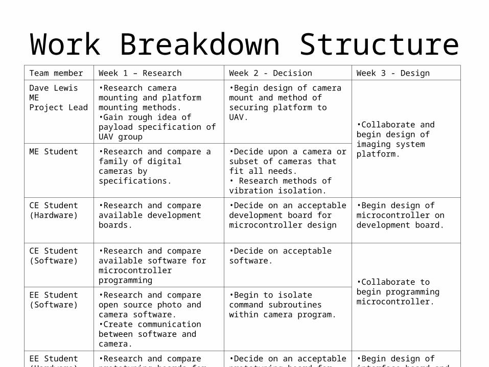
Work Breakdown StructureTeam member Week 1 – Research Week 2 - Decision Week 3 - Design
Dave Lewis MEProject Lead
•Research camera mounting and platform mounting methods.•Gain rough idea of payload specification of UAV group
•Begin design of camera mount and method of securing platform to UAV.
•Collaborate and begin design of imaging system platform.
ME Student •Research and compare a family of digital cameras by specifications.
•Decide upon a camera or subset of cameras that fit all needs. • Research methods of vibration isolation.
CE Student (Hardware)
•Research and compare available development boards.
•Decide on an acceptable development board for microcontroller design
•Begin design of microcontroller on development board.
CE Student(Software)
•Research and compare available software for microcontroller programming
•Decide on acceptable software.
•Collaborate to begin programming microcontroller.
EE Student(Software)
•Research and compare open source photo and camera software. •Create communication between software and camera.
•Begin to isolate command subroutines within camera program.
EE Student(Hardware)
•Research and compare prototyping boards for interface and power requirements for different systems.
•Decide on an acceptable prototyping board for interface design and power source.
•Begin design of interface board and power supply incorporation .• Ensure connections to UAV interface are correct.

Constraints
• Limited by size and weight restrictions of UAV payload constraints.
• Memory card storage limitations.• Camera’s maximum focal length.• Budget constraints.

Risk Assessment
• Change in UAV payload capacity or dimensions.
• Vendor issues for Printed Circuit Boards fabrication.
• Camera takes poor pictures in motion.• UAV interface failure.• UAV crash with system onboard.

Team Values and Norms
• Punctuality• Ethical• Through• Accurate• Communication• Collaboration

Resources
• Labs for board design.• Machine shop for platform fabrication.• 3D modeling software.• Respective EE and CE software.• Budget around $2000.