Embed Size (px)
Citation preview

P. M. Ajayan, L. S. Schadler, P. V. Braun
Nanocomposite Science and Technology
Nanocomposite Science and Technology. Edited by P.M. Ajayan, L.S. Schadler, P.V. BraunCopyright ª 2003 WILEY-VCH Verlag GmbH Co. KGaA, WeinheimISBN: 3-527-30359-6

Related Titles from Wiley-VCH
Caruso, F.
Colloids and Colloid Assemblies
2003, ISBN 3-527-30660-9
Decher, G., Schlenoff, J.B.
Multilayer Thin FilmsSequential Assembly ofNanocomposite Materials
2003, ISBN 3-527-30440-1
Gomez-Romero, P., Sanchez, C.
Functional Hybrid Materials
2003, ISBN 3-527-30484-3
Komiyama, M., Takeuchi, T., Mukawa, T.,Asanuma, H.
Molecular ImprintingFrom Fundamentals toApplications
2003, ISBN 3-527-30569-6
Krenkel, W.
High Temperature CeramicMatrix Composites
2001, ISBN 3-527-30320-0
Kohler, M., Fritzsche, W.
Nanotechnology
2004, ISBN 3-527-30750-8

P. M. Ajayan, L. S. Schadler, P. V. Braun
Nanocomposite Science and Technology

Pulickel M. Ajayan
Dept. of Materials Science and Engineering
Rensselaer Polytechnic Institute
Troy, NY 12180-3590
USA
Linda S. Schadler
Dept. of Materials Science and Engineering
Rensselaer Polytechnic Institute
Troy, NY 12180-3590
USA
Paul V. Braun
Dept. of Materials Science and Engineering
University of Illinois at Urbana-Champaign
Urbana, IL 61801
USA
This book was carefully produced. Nevertheless,
authors and publisher do not warrant the infor-
mation contained therein to be free of errors.
Readers are advised to keep in mind that state-
ments, data, illustrations, procedural details or
other items may inadvertently be inaccurate.
Library of Congress Card No.:
Applied for.
British Library Cataloguing-in-Publication Data:
A catalogue record for this book is available from
the British Library.
Die Deutsche Bibliothek –
CIP Cataloguing-in-Publication-Data
Bibliographic information published by
Die Deutsche Bibliothek
Die Deutsche Bibliothek lists this publication in the
Deutsche Nationalbibliografie; detailed
bibliographic data is available in the Internet at
http://dnb.ddb.de
ª 2003 WILEY-VCH Verlag
GmbH & Co. KGaA, Weinheim
All rights reserved (including those of translation
into other languages). No part of this book may be
reproduced in any form – by photoprinting,
microfilm, or any other means – nor transmitted
or translated into a machine language without
written permission from the publishers.
Registered names, trademarks, etc. used in this
book, even when not specifically marked as such,
are not to be considered unprotected by law.
Printed in the Federal Republic of Germany
Printed on acid-free paper
Composition Mitterweger & Partner, Plankstadt
Printing Strauss Offsetdruck GmbH, Morlenbach
Bookbinding Litges & Dopf Buchbinderei
GmbH, Heppenheim
Cover Design: Gunter Schulz, Fußgonheim
ISBN 3-527-30359-6

Contents
1 Bulk Metal and Ceramics Nanocomposites 1
Pulickel M. Ajayan
1.1 Introduction 1
1.2 Ceramic/Metal Nanocomposites 3
1.2.1 Nanocomposites by Mechanical Alloying 6
1.2.2 Nanocomposites from SolGel Synthesis 8
1.2.3 Nanocomposites by Thermal Spray Synthesis 11
1.3 Metal Matrix Nanocomposites 14
1.4 Bulk Ceramic Nanocomposites for Desired Mechanical Properties 18
1.5 Thin-Film Nanocomposites: Multilayer and Granular Films 23
1.6 Nanocomposites for Hard Coatings 24
1.7 Carbon Nanotube-Based Nanocomposites 31
1.8 Functional Low-Dimensional Nanocomposites 35
1.8.1 Encapsulated Composite Nanosystems 36
1.8.2 Applications of Nanocomposite Wires 44
1.8.3 Applications of Nanocomposite Particles 45
1.9 Inorganic Nanocomposites for Optical Applications 46
1.10 Inorganic Nanocomposites for Electrical Applications 49
1.11 Nanoporous Structures and Membranes: Other Nanocomposites 53
1.12 Nanocomposites for Magnetic Applications 57
1.12.1 Particle-Dispersed Magnetic Nanocomposites 57
1.12.2 Magnetic Multilayer Nanocomposites 59
1.12.2.1 Microstructure and Thermal Stability of Layered MagneticNanocomposites 59
1.12.2.2 Media Materials 61
1.13 Nanocomposite Structures having Miscellaneous Properties 64
1.14 Concluding Remarks on Metal/Ceramic Nanocomposites 69
V
Nanocomposite Science and Technology. Edited by P.M. Ajayan, L.S. Schadler, P.V. BraunCopyright ª 2003 WILEY-VCH Verlag GmbH Co. KGaA, WeinheimISBN: 3-527-30359-6

2 Polymer-based and Polymer-filled Nanocomposites 77
Linda S. Schadler
2.1 Introduction 77
2.2 Nanoscale Fillers 80
2.2.1 Nanofiber or Nanotube Fillers 80
2.2.1.1 Carbon Nanotubes 80
2.2.1.2 Nanotube Processing 85
2.2.1.3 Purity 88
2.2.1.4 Other Nanotubes 89
2.2.2 Plate-like Nanofillers 90
2.2.3 Equi-axed Nanoparticle Fillers 93
2.3 Inorganic FillerPolymer Interfaces 96
2.4 Processing of Polymer Nanocomposites 100
2.4.1 Nanotube/Polymer Composites 100
2.4.2 Layered FillerPolymer Composite Processing 103
2.4.2.1 Polyamide Matrices 107
2.4.2.2 Polyimide Matrices 107
2.4.2.3 Polypropylene and Polyethylene Matrices 108
2.4.2.4 Liquid-Crystal Matrices 108
2.4.2.5 Polymethylmethacrylate/Polystyrene Matrices 108
2.4.2.6 Epoxy and Polyurethane Matrices 109
2.4.2.7 Polyelectrolyte Matrices 110
2.4.2.8 Rubber Matrices 110
2.4.2.9 Others 111
2.4.3 Nanoparticle/Polymer Composite Processing 111
2.4.3.1 Direct Mixing 111
2.4.3.2 Solution Mixing 112
2.4.3.3 In-Situ Polymerization 112
2.4.3.4 In-Situ Particle Processing Ceramic/Polymer Composites 112
2.4.3.5 In-Situ Particle Processing Metal/Polymer Nanocomposites 114
2.4.4 Modification of Interfaces 117
2.4.4.1 Modification of Nanotubes 117
2.4.4.2 Modification of Equi-axed Nanoparticles 118
2.4.4.3 Small-Molecule Attachment 118
2.4.4.4 Polymer Coatings 119
2.4.4.5 Inorganic Coatings 121
2.5 Properties of Composites 122
2.5.1 Mechanical Properties 122
2.5.1.1 Modulus and the Load-Carrying Capability of Nanofillers 122
2.5.1.2 Failure Stress and Strain Toughness 127
2.5.1.3 Glass Transition and Relaxation Behavior 131
2.5.1.4 Abrasion and Wear Resistance 132
2.5.2 Permeability 133
2.5.3 Dimensional Stability 135
ContentsVI

2.5.4 Thermal Stability and Flammability 136
2.5.5 Electrical and Optical Properties 138
2.5.5.1 Resistivity, Permittivity, and Breakdown Strength 138
2.5.5.2 Optical Clarity 140
2.5.5.3 Refractive Index Control 141
2.5.5.4 Light-Emitting Devices 141
2.5.5.5 Other Optical Activity 142
2.6 Summary 144
3 Natural Nanobiocomposites, Biomimetic Nanocomposites,
and Biologically Inspired Nanocomposites 155
Paul V. Braun
3.1 Introduction 155
3.2 Natural Nanocomposite Materials 157
3.2.1 Biologically Synthesized Nanoparticles 159
3.2.2 Biologically Synthesized Nanostructures 160
3.3 Biologically Derived Synthetic Nanocomposites 165
3.3.1 Protein-Based Nanostructure Formation 165
3.3.2 DNA-Templated Nanostructure Formation 167
3.3.3 Protein Assembly 169
3.4 Biologically Inspired Nanocomposites 171
3.4.1 Lyotropic Liquid-Crystal Templating 178
3.4.2 Liquid-Crystal Templating of Thin Films 194
3.4.3 Block-Copolymer Templating 195
3.4.4 Colloidal Templating 197
3.5 Summary 207
4 Modeling of Nanocomposites 215
Catalin Picu and Pawel Keblinski
4.1 Introduction The Need For Modeling 215
4.2 Current Conceptual Frameworks 216
4.3 Multiscale Modeling 217
4.4 Multiphysics Aspects 220
4.5 Validation 221
Index 223
Contents VII

Preface
The field of nanocomposites involves the study of multiphase material where at leastone of the constituent phases has one dimension less than 100 nm. The promise ofnanocomposites lies in their multifunctionality, the possibility of realizing uniquecombinations of properties unachievable with traditional materials. The challengesin reaching this promise are tremendous. They include control over the distributionin size and dispersion of the nanosize constituents, tailoring and understanding therole of interfaces between structurally or chemically dissimilar phases on bulk proper-ties. Large scale and controlled processing of many nanomaterials has yet to beachieved. Our mentor as we make progress down this road is mother Nature andher quintessential nanocomposite structures, for example, bone.We realize that a book on a subject of such wide scope is a challenging endeavour.
The recent explosion of research in this area introduces another practical limitation.What is written here should be read from the perspective of a dynamic and emergingfield of science and technology. Rather than covering the entire spectrum of nanocom-posite science and technology, we have picked three areas that provide the basic con-cepts and generic examples that define the overall nature of the field. In the first chap-ter we discuss nanocomposites based on inorganic materials and their applications. Inthe second chapter polymer based nanoparticle filled composites are detailed with anemphasis on interface engineering to obtain nanocomposites with optimum perform-ance. The third chapter is about naturally occurring systems of nanocomposites andcurrent steps towards naturally inspired synthetic nanocomposites. Finally a shortchapter contributed by our colleagues highlights the possibility of using theoreticalmodels and simulations for understanding nanocomposite properties. We hopeour readers will find the book of value to further their research interests in this fas-cinating and fast evolving area of nanocomposites.
Troy, July 2003 P. M. Ajayan, L. S. Schadler and P. V. Braun
Contents IX
Nanocomposite Science and Technology. Edited by P.M. Ajayan, L.S. Schadler, P.V. BraunCopyright ª 2003 WILEY-VCH Verlag GmbH Co. KGaA, WeinheimISBN: 3-527-30359-6

1
Bulk Metal and Ceramics Nanocomposites
Pulickel Ajayan
1.1
Introduction
The field of nanocomposite materials has had the attention, imagination, and closescrutiny of scientists and engineers in recent years. This scrutiny results from thesimple premise that using building blocks with dimensions in the nanosize rangemakes it possible to design and create new materials with unprecedented flexibilityand improvements in their physical properties. This ability to tailor composites byusing nanosize building blocks of heterogeneous chemical species has been demon-strated in several interdisciplinary fields. The most convincing examples of such de-signs are naturally occurring structures such as bone, which is a hierarchical nano-composite built from ceramic tablets and organic binders. Because the constituents ofa nanocomposite have different structures and compositions and hence properties,they serve various functions. Thus, the materials built from them can be multifunc-tional. Taking some clues from nature and based on the demands that emerging tech-nologies put on building new materials that can satisfy several functions at the sametime for many applications, scientists have been devising synthetic strategies for pro-ducing nanocomposites. These strategies have clear advantages over those used toproduce homogeneous large-grained materials. Behind the push for nanocompositesis the fact that they offer useful new properties compared to conventional materials.The concept of enhancing properties and improving characteristics of materials
through the creation of multiple-phase nanocomposites is not recent. The idea hasbeen practiced ever since civilization started and humanity began producing moreefficient materials for functional purposes. In addition to the large variety of nanocom-posites found in nature and in living beings (such as bone), which is the focus ofchapter 3 of this book, an excellent example of the use of synthetic nanocompositesin antiquity is the recent discovery of the constitution of Mayan paintings developed inthe Mesoamericas. State-of-the-art characterization of these painting samples revealsthat the structure of the paints consisted of amatrix of clay mixed with organic colorant(indigo) molecules. They also contained inclusions of metal nanoparticles encapsu-lated in an amorphous silicate substrate, with oxide nanoparticles on the substrate
Nanocomposite Science and Technology. Edited by P.M. Ajayan, L.S. Schadler, P.V. BraunCopyright ª 2003 WILEY-VCH Verlag GmbH & Co. KGaA, WeinheimISBN: 3-527-30359-6
11

[1]. The nanoparticles were formed during heat treatment from impurities (Fe, Mn,Cr) present in the rawmaterials such as clays, but their content and size influenced theoptical properties of the final paint. The combination of intercalated clay forming asuperlattice in conjunction with metallic and oxide nanoparticles supported on theamorphous substrate made this paint one of the earliest synthetic materials resem-bling modern functional nanocomposites.Nanocomposites can be considered solid structures with nanometer-scale dimen-
sional repeat distances between the different phases that constitute the structure.These materials typically consist of an inorganic (host) solid containing an organiccomponent or vice versa. Or they can consist of two or more inorganic/organic phasesin some combinatorial form with the constraint that at least one of the phases or fea-tures be in the nanosize. Extreme examples of nanocomposites can be porous media,colloids, gels, and copolymers. In this book, however, we focus on the core concept ofnanocomposite materials, i.e., a combination of nano-dimensional phases with dis-tinct differences in structure, chemistry, and properties. One could think of the na-nostructured phases present in nanocomposites as zero-dimensional (e.g., embeddedclusters), 1D (one-dimensional; e.g., nanotubes), 2D (nanoscale coatings), and 3D(embedded networks). In general, nanocomposite materials can demonstratedifferent mechanical, electrical, optical, electrochemical, catalytic, and structural prop-erties than those of each individual component. The multifunctional behavior for anyspecific property of the material is often more than the sum of the individual compo-nents.Both simple and complex approaches to creating nanocomposite structures exist. A
practical dual-phase nanocomposite system, such as supported catalysts used in het-erogeneous catalysis (metal nanoparticles placed on ceramic supports), can be pre-pared simply by evaporation of metal onto chosen substrates or dispersal throughsolvent chemistry. On the other hand, material such as bone, which has a complexhierarchical structure with coexisting ceramic and polymeric phases, is difficult toduplicate entirely by existing synthesis techniques. The methods used in the prepara-tion of nanocomposites range from chemical means to vapor phase deposition.Apart from the properties of individual components in a nanocomposite, interfaces
play an important role in enhancing or limiting the overall properties of the system.Due to the high surface area of nanostructures, nanocomposites present many inter-faces between the constituent intermixed phases. Special properties of nanocompositematerials often arise from interaction of its phases at the interfaces. An excellent ex-ample of this phenomenon is the mechanical behavior of nanotube-filled polymercomposites. Although adding nanotubes could conceivably improve the strength ofpolymers (due to the superior mechanical properties of the nanotubes), a noninteract-ing interface serves only to create weak regions in the composite, resulting in no en-hancement of its mechanical properties (detailed in chapter 2). In contrast to nano-composite materials, the interfaces in conventional composites constitute a muchsmaller volume fraction of the bulk material.In the following sections of this chapter, we describe some examples of metal/cera-
mic nanocomposite systems that have become subjects of intense study in recentyears. The various physical properties that can be tailored in these systems for specific
1 Bulk Metal and Ceramics Nanocomposites2

applications is also considered, along with different approaches to synthesizing thesenanocomposites.
1.2
Ceramic/Metal Nanocomposites
Many efforts are under way to develop high-performance ceramics that have promisefor engineering applications such as highly efficient gas turbines, aerospace materials,automobiles, etc. Even the best processed ceramic materials used in applications posemany unsolved problems; among them, relatively low fracture toughness andstrength, degradation of mechanical properties at high temperatures, and poor resis-tance to creep, fatigue, and thermal shock. Attempts to solve these problems haveinvolved incorporating second phases such as particulates, platelets, whiskers, andfibers in the micron-size range at the matrix grain boundaries. However, resultshave been generally disappointing when micron-size fillers are used to achieve thesegoals. Recently the concept of nanocomposites has been considered, which is based onpassive control of the microstructures by incorporating nanometer-size second-phasedispersions into ceramic matrices [2]. The dispersions can be characterized as either
Fig. 1.1 New concept of ceramic metal nano-
composites with inter- and intra-granular designs:
properties of ceramic materials can be improved by
nanocomposite technology. This technique is based
on passive control of the microstructures by in-
corporating nanometer-sized second dispersions
into ceramic materials. This is a completely new
method to fabricate materials with excellent me-
chanical properties (such as high strength and
toughness), due to the desirable microstructure of
ceramics (Source:[228] Reprinted with permission)
1.2 Ceramic/Metal Nanocomposites 33

intragranular or intergranular (Figure 1.1). These materials can be produced by incor-porating a very small amount of additive into a ceramic matrix. The additive segregatesat the grain boundary with a gradient concentration or precipitates as molecular orcluster sized particles within the grains or at the grain boundaries. Optimized proces-sing can lead to excellent structural control at the molecular level in most nanocom-posite materials. Intragranular dispersions aim to generate and fix dislocations duringthe processing, annealing, cooling, and/or the in-situ control of size and shape ofmatrix grains. This role of dispersoids, especially on the nano scale, is importantin oxide ceramics, some of which become ductile at high temperatures. The intergra-nular nanodispersoids must play important roles in control of the grain boundarystructure of oxide (Al2O3, MgO) and nonoxide (Si3N4, SiC) ceramics, which improvestheir high-temperature mechanical properties [3–6]. The design concept of nanocom-posites can be applied to ceramic/metal, metal/ceramic, and polymer/ceramic com-posite systems.Dispersingmetallic second-phase particles into ceramics improves their mechanical
properties (e.g., fracture toughness). A wide variety of properties, including magnetic,electric, and optical properties, can also be, tailored in the composites due to the sizeeffect of nanosized metal dispersions, as described later in the chapter. Conventionalpowder metallurgical methods and solution chemical processes like sol–gel and co-precipitation methods have been used to prepare composite powders for ceramic/me-tal nanocomposites such as Al2O3/W, Mo, Ni, Cu, Co, Fe; ZrO2/Ni, Mo; MgO/Fe, Co,Ni; and so on. The powders are sintered in a reductive atmosphere to give homoge-neous dispersions of metallic particles within the ceramic matrices. Fracture strength,toughness, and/or hardness are enhanced due to microstructural refinement by thenanodispersions and their plasticity. For transitionmetal particle dispersed oxide cera-mic composites, ferromagnetism is a value-added supplement to the excellent me-chanical properties of the composites [7,8]. In addition, good magnetic response toapplied stress was found in these ceramic/ferromagnetic-metal nanocomposites, al-lowing the possibility of remote sensing of initiation of fractures or deformationsin ceramic materials.Nanocomposite technology is also applicable to functional ceramics such as ferro-
electric, piezoelectric, varistor, and ion-conducting materials. Incorporating a smallamount of ceramic or metallic nanoparticles into BaTiO3, ZnO, or cubic ZrO2 cansignificantly improve their mechanical strength, hardness, and toughness, whichare very important in creating highly reliable electric devices operating in severe en-vironmental conditions [9]. In addition, dispersing conducting metallic nanoparticlesor nanowires can enhance the electrical properties, as described later. Dispersion ofsoft materials into a hard ceramic generally decreases its mechanical properties (e.g.,hardness). However, in nanocomposites, soft materials added to several kinds of cera-mics can improve their mechanical properties. For example, adding hexagonal boronnitride to silicon nitride ceramic can enhance its fracture strength not only at roomtemperature but also at very high temperatures up to 1500 8C. In addition, some ofthese nanocomposite materials exhibit superior thermal shock resistance andmachin-ability because of the characteristic plasticity of one of the phases and the interfaceregions between that phase and the hard ceramic matrices.
1 Bulk Metal and Ceramics Nanocomposites4

Advanced bulk ceramic materials that can withstand high temperatures (>1500 8C)without degradation or oxidation are needed for applications such as structural parts ofmotor engines, gas turbines, catalytic heat exchangers, and combustion systems. Suchhard, high-temperature stable, oxidation-resistant ceramic composites and coatingsare also in demand for aircraft and spacecraft applications. Silicon nitride (Si3N4)and silicon carbide/silicon nitride (SiC/Si3N4) composites perform best in adversehigh-temperature oxidizing conditions. Commercial Si3N4 can be used up to1200 8C, but the composites can withstand much higher temperatures. Such Nano-composites are optimally produced from amorphous silicon carbonitride (obtained bythe pyrolysis of compacted polyhydridomethylsilazane [CH3SiH-NH]m[(CH3)2Si-NH]nat about 1000 8C), which produces crystallites of microcrystals of Si3N4 and nanocrys-tals of SiC [10] (Figure 1.2). The oxidation resistance, determined by TGA analysis,arises from the formation of a thin (few microns) silicon oxide layer.Processing is key to the fabrication of nanocomposites with optimized properties.
Some examples of commonly used processes for creating nanocomposites are dis-cussed below.
Fig. 1.2 Calculated phase diagrams of the system Si/B/C/N allows for the
creation of high-temperature ceramic nanocomposites. The system Si/B/C/N is
being investigated with respect to processing new covalent materials. Based
on this system, several nanocomposites (SiC/Si3N4) have been developed
that can, for example, withstand high temperatures (1500 8C) withoutdegradation or oxidation [10]. (Source [229] used with permission)
alternative web site: http://aldix.mpi-stuttgart.mpg.de/E_head.html,
used with permission
1.2 Ceramic/Metal Nanocomposites 55
1.2.1
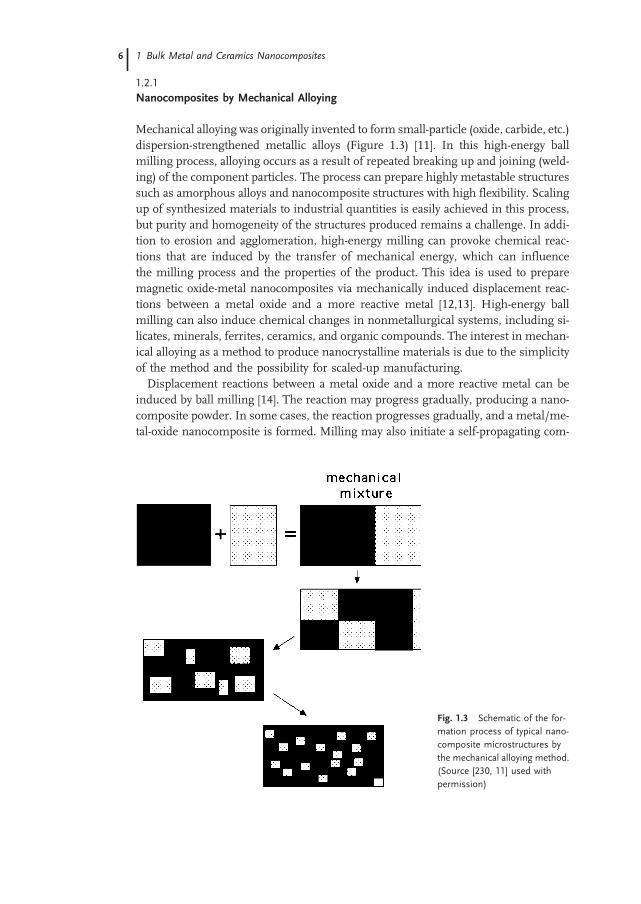
Nanocomposites by Mechanical Alloying
Mechanical alloying was originally invented to form small-particle (oxide, carbide, etc.)dispersion-strengthened metallic alloys (Figure 1.3) [11]. In this high-energy ballmilling process, alloying occurs as a result of repeated breaking up and joining (weld-ing) of the component particles. The process can prepare highly metastable structuressuch as amorphous alloys and nanocomposite structures with high flexibility. Scalingup of synthesized materials to industrial quantities is easily achieved in this process,but purity and homogeneity of the structures produced remains a challenge. In addi-tion to erosion and agglomeration, high-energy milling can provoke chemical reac-tions that are induced by the transfer of mechanical energy, which can influencethe milling process and the properties of the product. This idea is used to preparemagnetic oxide-metal nanocomposites via mechanically induced displacement reac-tions between a metal oxide and a more reactive metal [12,13]. High-energy ballmilling can also induce chemical changes in nonmetallurgical systems, including si-licates, minerals, ferrites, ceramics, and organic compounds. The interest in mechan-ical alloying as a method to produce nanocrystalline materials is due to the simplicityof the method and the possibility for scaled-up manufacturing.Displacement reactions between a metal oxide and a more reactive metal can be
induced by ball milling [14]. The reaction may progress gradually, producing a nano-composite powder. In some cases, the reaction progresses gradually, and a metal/me-tal-oxide nanocomposite is formed. Milling may also initiate a self-propagating com-
Fig. 1.3 Schematic of the for-
mation process of typical nano-
composite microstructures by
the mechanical alloying method.
(Source [230, 11] used with
permission)
1 Bulk Metal and Ceramics Nanocomposites6

bustive reaction [15]. The nature of such reactions depends on thermodynamic para-meters, the microstructure of the reaction mixture, and the way the microstructuredevelops during the milling process. The mechanical stresses developed duringhigh impact hits can also initiate combustion in highly exothermic systems, meltingthe reaction mixture and destroying the ultrafine (nanocrystalline) microstructure.Milling mixtures of ceramic and metal powders can induce mechanochemical reac-tions, and this process is an efficient way of producing nanocermets [16]. Dependingon the thermodynamics of the metal/metal-oxide systems and the kinetics of the ex-change (displacement) reactions during processing, various nanocomposite systemscould evolve. As an example, the reduction of metal oxides with aluminum duringreactive ball milling can result in nanocomposites of Al2O3 and metallic alloys (Fe,Ni, Cr; particularly binary alloy systems), and such ceramics with ductile metal inclu-sions produce toughened materials with superior mechanical properties [17]. Thesenanocomposite materials also have better thermomechanical properties, such as high-er thermal shock resistance, due to better metal–ceramic interfacial strength.Ball milling by direct milling of a mixture of iron and alumina powders has been
used to prepare nanocomposites with magnetic phases, such as nanoparticles of ironembedded in an insulating alumina matrix [18]. The average particle size can be re-duced to the 10-nm range, as indicated by x-ray diffraction linewidths and electronmicroscopy. The magnetic properties of this system (e.g., saturation magnetizationand coercivity) can be tailored by changing the phase composition, particle size,and the internal stresses accumulated during milling. In this system, the iron nano-particles were formed with lattice strains of about 0.005; coercivities up to 400 Oe wereachieved. The magnetization of the iron particles is 25%–40% less than that expectedfor bulk iron. Systems of smaller magnetic particles embedded in a nonmagnetic ma-trix can be prepared by high-energy ball milling [19]. For example, nanocomposites ofFe3O4 particles dispersed in Cu have been prepared by ball milling a mixture of Fe3O4
and Cu powders directly, as well as by enhanced ball milling-induced reaction betweenCuO and metallic iron [20]. Both processes result in magnetic semi-hard nanocom-posites with a significant superparamagnetic fraction, due to the very small particlesizes of the dispersed magnetic phase. In situ chemical reactions provide a means tocontrol the ball milling process and to influence the microstructure and magneticproperties of the product. Nanocomposite magnets (such as hard magnetic SmCoFephases in soft magnetic Fe/Co systems), discussed in detail later in this chapter, areroutinely prepared by mechanical milling and heat treatment. The metastable nano-crystalline/amorphous structures inherently obtained in mechanically alloyed pow-ders result from repeated deformation and fracture events during collisions of pow-ders with the balls. Plastic deformation in powders initially occurs through the forma-tion of shear bands, and when high dislocation densities are reached, the shear bandsdegenerate into randomly oriented subgrains. The large surface area of the nanocrys-talline grains often helps in the transformation of crystalline into amorphous struc-tures [21]. Deformation-induced defect density and the local changes in temperaturedue to impacts affect the diffusion coefficients of the several species involved duringthemilling process. In fact, the final microstructure and stoichiometry ofmechanicallymilled samples often reflects the competing processes ofmilling-induced disorder and
1.2 Ceramic/Metal Nanocomposites 77
diffusion-limited recovery, rather than being solely dependent on the starting material(e.g., depending on whether the starting mixtures are pre-alloyed or in their elementalforms).
1.2.2
Nanocomposites from Sol–Gel Synthesis
Aerogels, due to their high-porosity structure, are clearly an ideal starting material foruse in nanocomposites. Aerogels are made by sol–gel [22,23] polymerization of se-lected silica, alumina, or resorcinol-formaldehyde monomers in solution and are ex-tremely light (densities 0.5–0.001 g cc-1) but highly porous, having nanosize pores.In nanocomposites derived from aerogels, the product consists of a ‘substrate’ (e.g.,silica aerogel) and one or more additional phases (of any composition or scale). In thecomposites, there is always at least one phase whose physical structures have dimen-sions on the order of nanometers (the particles and pores of the aerogel). The addi-tional phases may also have nanoscale dimensions or may be larger. The systemsmostcommonly made are silica-based nanocomposite systems [24], but this approach canbe extended to other aerogel (alumina, etc.) precursors.Aerogel nanocomposites can be fabricated in various ways, depending on when the
second phase is introduced into the aerogel material. The second component can beadded during the sol–gel processing of the material (before supercritical drying). Itcan also be added through the vapor phase (after supercritical drying), or chemicalmodification of the aerogel backbone may be effected through reactive gas treat-ment. These general approaches can produce many varieties of composites. A non-silica material is added to the silica sol before gelation. The added material may bea soluble organic or inorganic compound, insoluble powder, polymer, biomaterial,etc. The additional components must withstand the subsequent processing stepsused to form the aerogel (alcohol soaking and supercritical drying). The conditionsencountered in the CO2 drying process are milder than in the alcohol drying processand are more amenable to forming composites. If the added components are bulkinsoluble materials, steps must be taken to prevent its settling before gelation. Theaddition of soluble inorganic or organic compounds to the sol provides a virtuallyunlimited number of possible composites. Two criteria must be met to prepare a com-posite by this route. First, the added component must not interfere with the gelationchemistry of the aerogel precursor. Possible interference is difficult to predict in ad-vance, but it is rarely a problem if the added component is reasonably inert. The secondproblem is the leaching out of the added phases during the alcohol soak or supercri-tical drying steps. This problem can be a significant impediment if a high loading ofthe second phase is desired in the final composite. When the added component is ametal complex, it is often useful to use a chemical binding agent that can bind to thesilica backbone and chelate the metal complex. Many use this method to prepare na-nocomposites of silica aerogels or xerogels. After the gel is dried, the resulting nano-composite consists of an aerogel with metal atoms or ions uniformly (atomically) dis-persed throughout the material. Thermal post-processing creates nanosize metal par-
1 Bulk Metal and Ceramics Nanocomposites8

ticles within the aerogel matrix. Such composites can have many applications. Anexample is their use as catalysts for gas-phase reactions or for catalyzed growth ofnanostructures.Vapor phase infiltration through the open pore network of aerogels provides another
route [25] to creating various forms of aerogel-based nanocomposites; almost any com-pound can be deposited uniformly throughout an aerogel. In fact, adsorbed materialsin silica aerogels can be modified into solid phases by thermal or chemical decom-position. The same is true for materials that have a porous interior structure, such
Fig. 1.4 (a) Microstructure of aerogel-encapsulated phase nanocomposite. (b) Left
image of three pieces of nanocomposites shows silica aerogel samples that have been
coated with silicon nanoparticles by chemical vapor methods. The composites emit red
light when excited with ultraviolet light. Right image of six pieces of nanocomposites
prepared by adding metal salts or other compounds to a sol before gelation; they show
different colors depending on the metal species present. The deep blue aerogel contains
nickel; the pale green, copper; the black, carbon and iron; the orange, iron oxide. (Source,
the silica aerogel photo gallery [231] used with permission)
1.2 Ceramic/Metal Nanocomposites 99

as zeolites. The nanosize pores within these porous hosts can be utilized for depositinga second phase by chemical or vapor phase infiltration and thermal decomposition.Recently, single-walled carbon nanotubes have been deposited within pores of zeolitesto create nanocomposite materials that have unique properties, such as superconduc-tivity [26].Some examples of nanocomposites (Figure 1.4) that have been created out of silica-
based aerogel matrices are the following:Silica aerogel/carbon composites [27]: These can be made by the decomposition of
hydrocarbon gases at high temperatures. The fine structure of aerogels allows thedecomposition to take place at a low temperatures (200–450 8C). Carbon loadingsof 1%–800% have been observed. The carbon deposition is uniform throughoutthe substrate at lower loadings, but at higher loadings, the carbon begins to localizeat the exterior surface of the composite. These nanocomposites have interesting prop-erties, such as electrical conductivity (above certain loadings) and higher mechanicalstrength relative to the aerogel.Silica aerogel/silicon composites [28]: Thermal decomposition of various organosilanes
on a silica aerogel forms deposits of elemental silicon. In this case, rapid decomposi-tion of the silane precursor leads to deposits localized near the exterior surface of theaerogel substrate. The nanocomposite, with 20–30-nm diameter silicon particles, ex-hibits strong visible photoluminescence at 600 nm.Silica aerogel/transition-metal composites [29]: Organo/transition-metal complexes
can be used to deposit metal compounds uniformly through the aerogel volumes.The compounds can be thermally decomposed to their base metals. These intermedi-ate composites, due to the disperse nature of the metallic phase and hence their highreactivity, can be converted to metal oxides, sulfides, or halides. The loading of themetallic phase can be changed by repeated deposition steps. The nanocompositescontain crystals of the desired metal species with sizes in the range of 5–100 nmin diameter.
Fig. 1.5 Photoluminescence
intensity (irradiance) vs. oxygen
pressure (concentration gives a
similar plot) at two temperatures
measured with a prototype sen-
sor made of silica aerogels. The
photoluminescence intensity is
indirectly proportional to the
amount of gaseous oxygen
within the aerogel. The quench-
ing of photoluminescence by
oxygen is observed in many
luminescent materials. Source
[232] used with permission)
1 Bulk Metal and Ceramics Nanocomposites10

The chemical structure of the silica (or other oxide) backbone of an aerogel can alsobe easily modified. For example, silica aerogel surfaces can be partially reduced byhydrogen. The resulting composite consists of thin interior surface layers of oxy-gen-deficient silica (SiOx). This material exhibits strong visible photoluminescenceat 490–500 nm when excited by ultraviolet (330 nm) light. The chemical processused to change the surface characteristics of the aerogel does not alter the physicalshape or optical transparency of the original structure. This composite is the founda-tion for the aerogel optical oxygen sensor [30] (Figure 1.5), which is based on the factthat the intensity of photoluminescence is indirectly related to the oxygen concentra-tion in the nanocomposite.
1.2.3
Nanocomposites by Thermal Spray Synthesis
Thermal spray processing is a commercially relevant, proven technique for processingnanostructured coatings [31]. Thermal spray techniques are effective because agglom-erated nanocrystalline powders are melted, accelerated against a substrate, andquenched very rapidly in a single step. This rapid melting and solidification promotesthe retention of a nanocrystalline phase and even amorphous structure. Retention ofthe nanocrystalline structure leads to enhanced wear behavior, greater hardness, andsometimes a reduced coefficient of friction compared to conventional coatings.Figure 1.6 shows a generalized thermal spray process [32]. To form the starting
powders, conventional powders can be cryomilled to achieve a nanocrystalline struc-ture [33–35]. Under the right conditions, for example, Fe alloyed with Al, precipitatesform, and these precipitates stabilize the nanoscale grain structure to 75% of the melt-ing temperature of the pure metal. Pure metals (except for aluminum) require somealloying before the nanocrystalline structure is stable at elevated temperatures [36]. ForWC/Co and Cr3Cr2/NiCr, the hard particles are broken into nanometer-size grains,and they are embedded in the binder [37, 38]. Other systems have also been milledfor thermal spraying, such as steel [39] and NiCr/Cr3C2. In all cases, there appears to besome nitrogen or oxygen contamination.The nanoscale powders, prepared by various techniques, must be agglomerated so
that grains on the order of 50 nm can be introduced into the thermal spray gun. Unlikesintering of ceramics, this agglomeration does not prevent full densification. A reason-ably narrow particle size distribution ensures uniform heating. Nanocrystalline feed-stock is generally injected internally (inside the torch), but powders can be injectedexternally. The type of flame or jet produced depends on the thermal spray techni-que, and within each technique, gas heating and gas flow parameters can controlthe velocity and temperature profile. The temperature and velocity profile, combinedwith the spray distance (the distance from the end of the nozzle to the substrate),control the temperature that the powders reach. Successive impact of particles in amolten or viscous state on the substrate or on previously deposited layers of materialforms a coating.The ability to maintain the nanocrystalline structure during processing and upon
consolidation is critical to improving its properties because it is the nanoscale micro-
1.2 Ceramic/Metal Nanocomposites 1111

structure that leads to the unique properties. Several parameters are critical: (a) Thethermal stability of the agglomerated powders: nanocrystalline materials can experi-ence grain growth at temperatures well below the temperatures observed for conven-tional materials. The high surface area drives this growth. (b) The degree of meltingthat occurs in flight: this can be controlled by the spray distance, the temperature of thejet, and the velocity of the jet, and optimal parameters are determined primarily byexperiment. (c) The cooling rate: a high cooling rate leads to high nucleation andslow grain growth, which promotes the formation of nanocrystalline grains. The sys-tems that tend to maintain their nanocrystalline structure even at elevated temperatureare apt to have impurities or a second phase that stabilize the grain structure [40]. Forexample, cryomilling often results in nanoscale particles (oxides, nitrides, or oxyni-trides) [41] that fix the grain boundaries. In addition, significant impurities or excesssolute atoms at the grain boundaries also limit grain growth [42, 43].Plasma spraying and high velocity oxy fuel (HVOF) processes are the most widely
used thermal spray methods for producing nanocrystalline and nanocomposite coat-ings. In plasma spraying, an electric arc is used to ionize an inert gas to produce ahighly energetic thermal plasma jet with gas temperatures and velocities of approxi-mately 11000 K and 2000ms-1. Vacuum plasma spraying and low-pressure plasmaspraying have been used to effectively process WC/Co nanocomposite coatings.Use of HVOF involves an internal combustion chamber in which fuel (hydrogen,propylene, acetylene, propane) is burned in the presence of oxygen or air (HVAF).This results in a hypersonic gas velocity. The particle velocities are higher than the800ms-1 achieved with plasma spray, and the thermal energy is lower (it may reach3000 K), which reduces superheating and particle vaporization. The high speed and
Thermal spraysource
TTorch variables- power- type of thermal energy- gas flow- gas composition- temperature- cooling
Feedstock variables- powder type- powder size and shape- carrier gas: flow and velocity- injection geometry
Jet variables- jet exit velocity and temperature- particle velocity and temperature- particle trajectory
Substrate variables- substrate type- substrate temperature
Particle variables- impact energy- impact angle- solidification state- rheology- morphology
Spray Distance
Coolingmechanismi
Fig. 1.6 Schematic for a generalized thermal spray
process, showing the different variables used. The
qualities of the coatings (bonding to the substrate,
microstructure of the coating, hardness, wear re-
sistance, etc.) are affected by a multidimensional
parameter space
1 Bulk Metal and Ceramics Nanocomposites12

low temperatures result in more strongly adhering and more homogeneous coatingswith lower oxide content.WC/Co coatings are of great interest because they already exhibit excellent wear
properties. Nanostructuring further increases the wear resistance and decreasesthe coefficient of friction. Thermally sprayed WC/Co coatings, however, do not alwaysexhibit improved properties. WC/Co coatings sprayed via HVOF exhibited decreasedwear resistance due to decomposition of the carbide phase during spraying [44]. Na-nostructured powders reach temperatures almost 500 8 higher than their conventionalcounterparts. Vacuum plasma spraying, however, resulted in coatings with signifi-cantly improved wear resistance and lower coefficient of friction, presumably becausethe Ar atmosphere prevented oxidation of the carbide phase [45].Cr3C2/NiCr composites are also used in applications where wear resistance is re-
quired, but they have an added advantage over WC/Co, which has excellent corrosionresistance. Nanostructuring of these coatings has also resulted in improved hardnessand scratch resistance, as well as reduced coefficient of friction. The improved homo-
Fig. 1.7 Microstructures of
thermal-sprayed Cr3C2/NiCr
coatings. Top micrograph shows
conventional coating and bot-
tom micrograph shows nano-
composite microstructure.
A uniform, dense microstructure
is observed in the nanostruc-
tured coatings, compared to an
inhomogeneous microstructure
in the conventional coating.
(Source [37] used with permis-
sion)
1.2 Ceramic/Metal Nanocomposites 1313

geneity of these structures, as well as a high density of Cr2O3 nanoparticles (formed byoxidation during the thermal spray process), compared to conventional materials,cause the improved properties. Figure 1.7 shows an example of the improved homo-geneity of nanostructured coatings. Ceramics such as alumina/titania and zirconiahave also been thermally sprayed, and the nanostructured powders have lead to sub-micron final grain sizes in the coatings. Key to achieving excellent properties is mini-mizing the degree of melting [46] so as to maintain the nanostructure in the finalcoating. On the other hand, significant deformation or splatting of the particles isrequired upon impact, to assure a large surface contact between the particles [47].Thus, some melted particles lend well to continuous, good-quality coatings.
1.3
Metal Matrix Nanocomposites
During the past decade, considerable research effort has been directed towards thedevelopment of in situ metal-matrix composites (MMCs), in which the reinforce-ments are formed by exothermal reactions between elements or between elementsand compounds [48]. With this approach, MMCs with a wide range of matrix materi-als (including aluminum, titanium, copper, nickel, and iron), and second-phase par-ticles (including borides, carbides, nitrides, oxides, and their mixtures) have been pro-duced. Because of the formation of stable nanosized ceramic reinforcements, in situMMCs exhibit excellent mechanical properties.MMCs are a kind of material in which rigid ceramic reinforcements are embedded
in a ductile metal or alloy matrix. MMCs combine metallic properties (ductility andtoughness) with ceramic characteristics (high strength andmodulus), leading to great-er strength to shear and compression and to higher service temperature capabilities.The attractive physical and mechanical properties that can be obtained with MMCs,such as high specific modulus, strength, and thermal stability, have been documentedextensively. Interest in MMCs for use in the aerospace and automotive industries andother structural applications has increased over the past 20 years. This increase resultsfrom the availability of relatively inexpensive reinforcements and the development ofvarious processing routes that result in reproducible microstructure and properties.The family of discontinuously reinforced MMCs includes both particulates and
whiskers or short fibers. More recently, this class of MMCs has attracted considerableattention as a result of (a) availability of various types of reinforcement at competitivecosts, (b) the successful development of manufacturing processes to produce MMCswith reproducible structure and properties, and (c) the availability of standard or near-standard metal working methods, which can be utilized to fabricate these composites.The particulate-reinforced MMCs are of particular interest due to their ease of fabrica-tion, lower costs, and isotropic properties. Traditionally, discontinuously reinforcedMMCs have been produced by several processing routes such as powder metal-lurgy, spray deposition, mechanical alloying (MA), and various casting techniques.All these techniques are based on the addition of ceramic reinforcements to the matrixmaterials, which may be in molten or powder form. For conventional MMCs, the
1 Bulk Metal and Ceramics Nanocomposites14
reinforcing phases are prepared separately prior to the composite fabrication. Thus,conventional MMCs can be viewed as ex situ MMCs. In this case, the scale of thereinforcing phase is limited by the starting powder size, which is typically on the orderof micrometers to tens of micrometers and rarely below 1 lm. Other main drawbacksthat must be overcome are interfacial reactions between the reinforcements and thematrix and poor wettability between the reinforcements and the matrix due to thesurface structure of the reinforcements as well as to contamination.The properties of MMCs are widely recognized to be controlled by the size and
volume fraction of the reinforcements as well as by the nature of the matrix/reinforce-ment interfaces. An optimum set of mechanical properties can be obtained when fine,thermally stable ceramic particulates are dispersed uniformly in the metal matrix.Efforts have been made to meet such requirements and have led to the developmentof novel composites – in situ MMCs in which the reinforcements are synthesized in ametallic matrix by chemical reactions between elements or between element and com-pound during fabrication of the composite. Compared with conventional MMCs pro-duced by ex situ methods, in situ MMCs exhibit the following advantages: (a) forma-tion of reinforcements that are thermodynamically stable in the matrix, leading to lessdegradation in elevated-temperature services; (b) reinforcement/matrix interfaces thatare clean, resulting in strong interfacial bonding; (c) the formation of reinforcing par-ticles of a finer size with a more uniform distribution in the matrix, which yields bettermechanical properties.The great potential that in situ metal matrix nanocomposites offer for widespread
applications has resulted in the development of a variety of processing techniques forproduction during the past decade. Using these routes, in situ composites with a widerange of matrix materials (including aluminum, titanium, copper, nickel, and iron)and second-phase particles (including borides, carbides, nitrides, oxides, and theirmixtures) have been produced. Particularly attractive among the several techniquesavailable for synthesizing MMCs are the solidification processes in which the reinfor-cing particles are formed in situ in the molten metallic phase prior to its solidification.What makes them so attractive is their simplicity, economy, and flexibility. The judi-cious selection of solidification processing techniques, matrix alloy compositions, anddispersoids can produce new structures and affect a unique set of useful engineeringproperties that are difficult to reach in conventional monolithic materials. Specifically,the solidification conditions that are present during processing play an important rolein dictating the microstructure and the mechanical and physical characteristics ofthese structures. Microstructure refinement arising from rapid solidification proces-sing (RSP) offers a potential avenue for alleviating solute segregation and enhancingdispersion hardening by substantially reducing the size of the reinforcing phases andmodifying their distribution in the matrix. As example, RSP of Ti/B or Ti/Si alloysaccompanied by large undercoolings and high cooling rates is very effective in produ-cing in situ Ti-based nanocomposites containing large volume fractions of reinforcingparticles [49]. These particles are formed in situ in Ti/B or Ti/Si alloys either uponsolidification or, subsequently, by controlled decomposition of the resulting supersa-turated solid solutions.
1.3 Metal Matrix Nanocomposites 1515

More recently, several workers have used the RSP route [50] to fabricate in situ TiCparticulate-reinforced Al-based composites. In their work, master material ingots wereprepared by melting a mixture of Al, Ti, and graphite powder in a graphite-lined in-duction furnace under an argon atmosphere, followed by direct chill cast. Chill blockmelt spinning was used to prepare rapidly solidified samples in ribbon form. Theseribbons were further milled into powders (100 250 lm), which were subsequentlycanned and degassed and then extruded into rods. In situ formed TiC particles of 4080 nm were reported to be distributed uniformly in the aluminummatrix with a grainsize of 0.3 0.85 lm. The authors reported that RSP can significantly refine themicrostructure of the composites. For TiC/Al composites, the microstructure is oftencharacterized by the presence of agglomerated TiC particles. These particles, with asize of 0.2 1.0 lm, accumulate at the Al subgrain or the grain boundaries. The largerparticles have polyhedral morphology, and the smaller ones are round or globular. Incomparison, typical rapidly solidified microstructures consist of a uniform, fine-scaledispersion of TiC particles with a size of 40 80 nm in an Al supersaturated matrix of0.30 0.85 lm grain size. One main advantage of RSP is its ability to produce alloycompositions not obtainable by conventional processing methods. Furthermore, RSPmaterials have excellent compositional homogeneity, small grain sizes, and homoge-neously distributed fine precipitates or dispersoids.The homogeneity of composite materials is crucially important to high-performance
engineering applications such as in the automotive and aircraft industries. A uniformreinforcement distribution in MMCs is essential to achieving effective load-bearingcapacity of the reinforcement. Nonuniform distribution of reinforcement can leadto lower ductility, strength, and toughness of the composites. Nanoscale ceramic par-ticles synthesized in situ are dispersed more uniformly in the matrices of MMCs,leading to significant improvements in the yield strength, stiffness, and resistanceto creep and wear of the materials. For example, in situ fabrication of TiC-reinforcedAl, Al/Si, and Al/Fe/V/Si matrix composites by the RSP route is far more effective in
Fig. 1.8 Increase in strength (r) of in-situ fabri-
cated TiC-reinforced Al nanocomposites with in-
creasing volume fractions or decreasing diameters
of dispersed-phase (TiC) particles. (Source [50]
used with permission)
1 Bulk Metal and Ceramics Nanocomposites16

improving the tensile properties of these composites, due to the formation of a refinedmicrostructure. The in situ composites exhibit excellent strength at room temperatureand elevated temperatures. The values of strength (r) increased with increasing vol-ume fractions or decreasing diameters of dispersed-phase (TiC) particles (Figure 1.8).When the volume fraction of dispersed particles is about 15–30 vol % and the particlediameters 40–80 nm, the values of r are 120–270 MPa and 200–350 MPa, respec-tively (Figure 1.8).Nanocrystalline materials in general are single- or multi-phase polycrystals with
grain sizes in the nanometer range. Owing to the extremely small dimensions,many properties of nanocrystalline samples are fundamentally different from, andoften superior to, those of conventional polycrystals and amorphous solids. For exam-ple, nanocrystalline materials exhibit increased strength or hardness, improved duc-tility or toughness, reduced elastic modulus, enhanced diffusivity, higher specific heat,enhanced thermal expansion coefficient, and superior soft magnetic properties incomparison with conventional polycrystalline materials [51]. Crystallizing completelyamorphous solids under proper heat treatment conditions can result in formation ofnanocrystalline materials. However, controlled crystallization of amorphous alloys can
Tab. 1.1 Typical magnetic properties of nanocrystal/amorphous
composites and amorphous alloys. Alloy 1: Fe73.5 Cu1 Nb3 Si13.5 B9
(at. %). Alloy 2: Fe73.5 Cu1 Nb3 Si16.5 B6 (at. %).
Core loss: 100 kHz, 0.2 T [52].
Alloy t
(lm)
Bs
(T)
Br /Bs
(%)
Hc
(A m-1)
lc
(1 kHz)
Core loss
(kW/m-3)
ks
(10-6)
Curie temp.
(K)
Alloy 1 18 1.24 54 0.53 100000 280 +2.1 843
Alloy 2 18 1.18 58 1.1 75000 280 0 833
Fe/Si/B/M 20 1.41 16 6.9 6000 460 +20 631
Co/Fe/Si/B/M 18 0.53 50 0.32 80000 300 0 453
Fig. 1.9 Compressive stress–
strain curves of amorphous
and partly crystallized
Zr57Al10Cu20Ni8Ti5 alloy nano-
composite (a) as-cast, (b) 40 vol.
% nanocrystals, (c) 45 vol. %
nanocrystals and (d) 68 vol. %
nanocrystals. The sample con-
taining a volume fraction of 40%
nanocrystals (b) seems to pro-
vide the best compromise be-
tween strength and ductility.
(Source [53] used with permis-
sion)
1.3 Metal Matrix Nanocomposites 1717

be used to obtain partially crystallized materials with nanosized crystallites embeddedin the residual amorphous matrix. This special nanocrystal/amorphous nanocompo-site structure allows the materials to exhibit excellent mechanical or magnetic proper-ties. The Fe/Cu/Nb/Si/B alloys are a good example of this type of material. The Fe/Si/B/M (M: additives) alloys properly prepared by annealing amorphous alloys and hav-ing bcc Fe solid solution and 10-nm-diameter nanostructures embedded in the resi-dual amorphous matrix, show excellent soft magnetic properties (Table 1.1). The na-nocrystal/amorphous composite shows high saturation flux density, lowmagnetostric-tion, and excellent soft magnetic properties. This nanocomposite, therefore, is ex-pected to find use in many kinds of magnetic devices such as choke coils and trans-formers.Production of bulk nanostructured composites with amorphous matrices has been
carried out by die casting and mechanical alloying and subsequent consolidation atelevated temperatures in Zr-based alloys [53]. The distribution of finely dispersed na-nocrystals increases the flow stress significantly. For example, a Zr57Al10Cu20Ni8Ti5sample containing a volume fraction of 40% nanocrystals (Figure 1.9, curve b) seemsto provide the best compromise between strength and ductility.
1.4
Bulk Ceramic Nanocomposites for Desired Mechanical Properties
Over the past half century, ceramics have received significant attention as candidatematerials for use as structural materials under conditions of high temperature, wear,and chemical attack that are too severe for metals. However, one characteristic of theseceramics that has prevented them from being widely used is their inherent brittleness.Thus, significant scientific effort has been directed towards making ceramics moreflaw-tolerant through design of their microstructure. An important example ofhigh-toughness structural ceramics is self-reinforced silicon nitrides, which were firstdeveloped during the 1970s [54]. These materials have high toughness and room-tem-perature strength, along with good resistance to corrosion and oxidation. However,their high-temperature (>1000 8C) strength is compromised by low creep resistanceand the occurrence of subcritical crack growth. These phenomena are caused by thesoftening of a glassy phase that is located at the grain boundaries as the temperature isincreased. A possible way to overcome this problem is the fabrication of Si3N4/SiCnanocomposites [55]. Also, several approaches have been used to improve the proces-sability (the sinterability of these materials is rather poor) and high-temperature prop-erties of monolithic silicon nitrides, with limited success.Considerable attention has been devoted to ‘functionally graded nanocomposite ma-
terials’, for which gradually varying the dispersion (nanoparticles) to matrix ratio inchosen directions continuously changes the material. An example of such a material isSiC dispersions in a C (pyrolytic graphite) matrix, which has served well as thermalbarriers on the space shuttle due to its excellent resistance to oxidation and thermalshock. One route to preparing these composite systems is by chemical vapor deposi-tion using multicomponent gas reactions. For example, 10–100-nm sized SiC disper-
1 Bulk Metal and Ceramics Nanocomposites18

sions can be prepared with pyrographite using precursors of SiCl4/C3H8/H2 or SiCl4/CH4 in CVD. The entire range of compositions from carbon to SiC has been preparedby this method [56]. Changing the deposition conditions can control the morphologiesof the second phase and hence the microstructure of the composites; this control in-fluences the mechanical properties of the material. Nanocrystalline carbide-embeddedcomposites, particularly those with amorphous or diamond-like carbon matrices, canbe considered for tribological applications. The challenges here are to minimize for-mation of the sp2 soft graphite-like phase during synthesis and to retain a high fractionof the hard a-C matrix. Pulsed laser deposition (in which laser-ablated plumes fromgraphite are intercepted by a low-energy metal plasma produced by magnetron sput-tering) [57] at near room temperature has been used successfully to create 10 nmTiC/TiCN nanocrystals embedded uniformly in a-C with diamond-like characteris-tics. Hardness values as high as 60 GPa, coefficient of friction values as low as0.1, and high toughness values have been achieved in these films, which havehigh tribological value and possible applications in surface-protection coating technol-ogies. The two-phase heterogeneous structure in the nanocomposites provides crackdeflectionmechanisms, reducing the tendency toward easy brittle failure in these hardcomposites.Significant interest was generated in 1991 whenNiihara [58] reported large improve-
ments in both the fracture toughness and the strength of materials with a uniquemicrostructure: ceramics with nanometer-range particles (20–300 nm) embeddedwithin a matrix of larger grains and at their grain boundaries. These ceramics report-edly showed up to 200% improvement in both strength and fracture toughness, betterretention of strength at high temperatures, and better creep properties. Materials likeSiC, Al2O3, ZrO2 and Si3N4 are excellent candidates for demanding structural applica-tions due to their mechanical and thermomechanical properties (Figure 1.10) [59]. Theincorporation of fine SiC and Si3N4 particles (smaller than 300 nm) in an alumina
Fig. 1.10 Mechanical properties of a SiC/zirconia-toughened mullite nano-
composite as a function of nanosized SiC content. (Source [59] used with
permission)
1.4 Bulk Ceramic Nanocomposites for Desired Mechanical Properties 1919

(Al2O3, a structural ceramic material) matrix first demonstrated the concept of struc-tural nanocomposites. The dispersion of these particles improved the fracture tough-ness from 3 to 4.8 MPa m1/2 and the strength from 350 to 1050 MPa at only 5 vol. %additions of SiC [60]. The bending strength of such composite was also measured to be 1 GPa. Further improvements in strength to about 1500 MPa were achieved byannealing the samples at 1300 8C. The high strengths were maintained to about1000 8C. For Si3N4/SiC nanocomposites, several processing techniques have beenused, including conventional powder processing, sol–gel processing, and polymerprecursor processing; the SiC particles can originate from admixed commercialSiC powders, SiCN powders produced by plasma synthesis, in situ reaction pyrolysisof carbon-coated Si3N4 particles, and pyrolysis of a polycarbosilane based on SiCNprecursor. An example of conventional processing is co-milling of the solid precursorpowder materials followed by hot pressing, which produces nanocomposites posses-sing both inter- and intra- granular SiC particles [61]. Intragranular particles are mosteffective in toughening the material, because they are mainly responsible for crackdeflection and crack impediment. Intergranular particles are often detrimental (in-itiating cracks), but they could provide some advantages by grain refinement duringprocessing. The toughness of the composite depends on the volume fractions of thesetwo types of dispersoids, and controlling these fractions precisely is challenging. Inpolymer-based processing, a mixture of Si3N4 powder, sintering additives, and poly-methylphenylsilane is pyrolyzed at 1000 8C in Ar and sintered in nitrogen. Anotherpossibility is preparing an amorphous Si/N/C powder by crosslinking and pyrolysis ofpolymethylsilazane [62]. Whereas the conventional process leads to a micronanostruc-ture with nano-sized SiC dispersions mainly inside Si3N4 grains, the polymer-proces-sing route results in atto (nano-nano) structures. Hybrid polymer/powder processingcan also be applied to other composite microstructures such as Al2O3/SiC. Coating asilicon-containing polymer (polycarbosilane) onto alumina powder, followed by pyr-olysis, can result in a finer SiC nanophase [63]. Novel, superior processing routescan be used to prepare well dispersed ceramic nanocomposites, for exampleAl2O3/SiC. Colloidal consolidation and reaction sintering is one such process [64]:micro-size particles of the two phases are colloidally dispersed and consolidated toform uniform compacts. The SiC phase particles are then oxidized to reduce themto nanometer-size cores. The interfacial reaction between the oxidized SiC particlesand the alumina matrix produces mullite. The advantage of this process is that particlesizes need not be brought down to nanoscale by milling and can be controlled well byoxidation. Also, due to the volume increase that occurs during reaction sintering,shrinkages often seen during sintering are small.Materials fabricated from polymer-derived powders made by hot pressing have
yielded the best mechanical properties. These techniques are expensive and limitthe shapes that can be fabricated. Gas-pressure sintering or pressure-less sinteringare the most attractive processing techniques. However, to date, research on gas-pres-sure sintering has used mixed powders, which result in poor powder dispersion, ag-glomeration of SiC, and changes in the glass phase chemistry due to reaction with SiC.Thus, the focus for future processing rests on routes that produce commercially viablepowders with uniform dispersion of SiC particles (with controlled size and volume
1 Bulk Metal and Ceramics Nanocomposites20

fraction) that can be fabricated into dense components by gas-pressure or pressure-lesssintering. The effects of reinforcement on the mechanical properties of silicon nitridenanocomposites is not well understood. As with the Al2O3/SiC nanocomposites, thepresence of the SiC at the grain boundaries restricts grain growth, resulting in theformation of a matrix of finer Si3N4 grains. In fact, at higher volume percent of re-inforcements, grain growth is reported to be severely restricted, resulting in fine a-Si3N4 grains and a composite showing superplastic (large strain to failure) beha-vior. The ‘nanosize’ strengthening and toughening effect due to thermal expansionmismatch proposed for Al2O3/SiC composites needs to be critically examined forSi3N4/SiC composites: the difference between the thermal expansion coefficientsof Si3N4 and SiC is small and in the opposite sense as in Al2O3/SiC. The presenceof a liquid phase in Si3N4 and its composites further complicates matters: reactionsbetween the reinforcements and the liquid phase could alter its composition and quan-tity, thus changing the sintering behavior and creep resistance. Thus, a more funda-mental understanding of the effect of nanosized SiC reinforcements on the behaviorof Si3N4 matrix composites is required. In particular, systematic studies of the effectsof reinforcement size and volume fraction on the microstructure, processing, andproperties of these nanocomposites are needed. Such studies exist for compositesin which the reinforcement size is in the several-micron range, and in these stu-dies, both the reinforcement size and volume fraction significantly affect the fracturetoughness and strength [65].For unreinforced Si3N4 ceramics, there is sufficient evidence that creep in the liquid
phase-sintered materials is controlled by grain boundary transport and sliding. Thus,the incorporation of fine reinforcements at the grain boundaries may improve creepresistance [66]. The amount and viscosity of the intergranular phase due to chemicalreactions and accelerated crystallization, the hindrance of grain-boundary sliding dueto fixing by SiC particles, and the obstruction of easy diffusion paths by the SiC par-ticles explain the better creep resistance of the nanocomposites [67]. For Al2O3/SiCnanocomposites, the better creep resistance (5 vol. % SiC nanoparticles reducesthe tensile creep of Al2O3 by 2–3 orders of magnitude) is explained by SiC nanopar-ticles fixing the grain boundaries, resulting in less grain-boundary sliding, a smallviscoelastic contribution to creep, and enhanced grain-boundary strength, allowingplastic deformation of grains through dislocation motion [68]. The presence of non-bridged grain boundaries causes a rearrangement of the microstructure due to initialgrain sliding. But this initial sliding process is stopped easily as boundaries fixed by theSiC nanoparticles are encountered; hence, only lattice mechanisms based on disloca-tion motion or, to a lesser extent, viscoelastic mechanism, contribute to creep. How-ever, in general, the studies on nanocomposites and the exact mechanisms of creepresistance have not been entirely conclusive, and systematically investigating the ef-fects of various microstructural parameters as a functions of particle size, oxidation,and volume of the dispersed phase is desirable. An additional factor that needs carefulcontrol is the volume fraction of reinforcements on the grain boundary as opposed towithin the grain. The erosion properties of such composites also deservemention. Theresidual surface stress induced by grinding and polishing nanocomposites (e.g.,Al2O3/SiC) and monolithic alumina are quite different, and studies show that the
1.4 Bulk Ceramic Nanocomposites for Desired Mechanical Properties 2121

residual surface stress in the nanocomposite is more sensitive to surface treatmentthan that in the corresponding monolithic structure. Direct observations by transmis-sion electron microscopy suggest that deformation micromechanisms, from twinningin the alumina to dislocation generation in the nanocomposite, dominate the plasticdeformation induced by the surface treatments.Crack-tip bridging by particles is a primary mechanism of strengthening ceramic
nanocomposites. Small brittle particles (for example, silicon carbide particles in Al2O3/SiC composites) cause crack tip bridging at small distances behind the cracks [69].Residual stresses around the particles cause the strengthening mechanism to operateeffectively even at small volume fraction loading of SiC. The increase in the nanocom-posite strength due to the reduction in the critical flaw size is achieved by the finedispersion of nanoparticles [70]. Intergranular fracture, which is responsible for frac-ture in monolithic alumina, is suppressed in the nanocomposite, because the crackextension along grain boundaries is suppressed by particles that strongly bond thematrix–matrix interfaces. Hence, transgranular fracture is a common mode of frac-ture in nanocomposites. Tensile stresses in the intragranular particles induce thecracks to extend to the particles, leading to particle bridge toughening.Finally, dispersing metallic second-phase particles into ceramics is not only suitable
for improving themechanical properties of ceramics, but also presents a wide variety ofadvantages for addition of new functions such asmagnetic, electric, and optical proper-ties, due to the size effect of nanosized metal dispersion. Granular films can be madewith a ceramic phase embedded with nanosize metal granules [71] (e.g., Fe/Al2O3, Fe/SiO2). Such films display unusual and often enhanced transport, optical, andmagneticproperties. An important parameter that affects the physical behavior of granular filmsis the percolation threshold of the embedded metal phase. Percolation effects in na-nocomposites are discussed later in this chapter. A dramatic manifestation of thispercolation effect is the change, by many orders of magnitude, of the electrical resis-tivity (insulator-to-metal transition) as the percolation threshold is passed. The percola-tion threshold is generally found tobe in the rangeof 0.5–0.6metal volume fractions fornanocomposite films [72]. The mechanical properties can also undergo changes nearthe percolation threshold. The obvious explanation for this is that a change occurs indeformation behavior as the embedded phase forms connected networks that spreadthrough the matrix phase. Conventional powder metallurgical methods and solutionchemical processes like sol–gel, and coprecipitation methods can also be used to pre-pare composite powders for ceramic/metal nanocomposites such as Al2O3/W, Mo, Ni,Cu, Co, Fe; ZrO2/Ni, Mo; MgO/Fe, Co, Ni and so on. They are sintered in a reductiveatmosphere that gives homogeneous dispersion ofmetallic particleswithin the ceramicmatrices. Themicrostructural refinement bynanodispersion and the plasticity enhancethe fracture strength, toughness, and/or hardness.In summary, the advantage of ceramic nanocomposites lies not only in the mechan-
ical strength of the composite material but also in other mechanical properties such asfracture toughness, hardness, and creep resistance. The degree of improvement inthese properties depends on the composite systems involved. Although there aresome generalities in the strengthening and toughening mechanisms in such compo-sites, such as crack deflection and crack-tip bridging by the dispersed particles, the
1 Bulk Metal and Ceramics Nanocomposites22

actual size, location, and volume fraction of particles strongly influence the final out-come with respect to mechanical behavior.
1.5
Thin-Film Nanocomposites: Multilayer and Granular Films
Thin-film nanocomposites are films consisting of more than one phase, in which thedimensions of at least one of the phases is in the nanometer range. These nanocom-posite films can be categorized as multilayer films, in which the phases are separatedalong the thickness of the film, or granular films, in which the different phases aredistributed within each plane of the film (Figure 1.11). Multilayered thin-film nano-composites consist of alternating layers of different phases and have a characteristicthickness on the order of nanometers. These films are usually used for their enhancedhardness, elastic moduli, and wear properties. The elastic moduli is higher in multi-layered thin films than in homogeneous thin films of either component. The super-modulus effect [73] is observed in some metallic systems, by which, at certain char-acteristic thicknesses (typically 2 nm, corresponding to a bilayer consisting of onelayer of each phase) of the film, the elastic modulus increases bymore than 200%. Themost satisfactory explanation of this effect assumes an incoherent interface betweenthe adjacent layers [74], suggesting that atoms are displaced from their equilibriumpositions and that, during loading, all the layers undergo compression, which resultsin a higher resistance to deformation. The increase in hardness of the multilayer na-nocomposites has been explained [75] by considering that, when ultrathin films ofmaterials with different dislocation line lengths are stacked, the strength approachesthe theoretical limit. The dislocations cannot move from layer to layer, due to thedifference in dislocation line lengths, and the films are thin enough that independentdislocation sources do not become operative. Conventional thin-film deposition tech-niques (sputtering, physical vapor deposition, CVD, electrochemical deposition, etc.)can produce multilayer nanocomposites, and the excellent flexibility of these techni-ques creates extremely thin films of uniform compositions.
Fig. 1.11 Schematic of possible microstructures for nanocomposite and nanostructured coatings:
isotropic dispersed multiphase microstructure (e.g., TiC/amorphous carbon), multilayered mi-
crostructure (e.g., TiN/TiC) for nanocomposite coatings, and homogeneous alloyed microstructure
as possible homogeneous nanostructured coatings (e.g., NiCoCrAlY alloy)
1.5 Thin-Film Nanocomposites: Multilayer and Granular Films 2323

Granular nanocomposite films are those that contain both phases (metal and cera-mic) in the same layer of the film and have no abrupt interfaces across the film thick-ness as in multilayer films. Here, one phase can be in the nanosize range (similar todispersions), or both phases can have nanocrystalline grains distributed contiguouslyand laterally in the film. Granular nanocomposite coatings are also common; in these,the matrix phase is a polymer and the dispersed phase is inorganic. Granular films inwhich at least one distributed phase has electrical/magnetic properties aremainly usedin electrical and magnetic applications [76]. In certain systems consisting of metal andceramic particles (such as iron oxide/silver and alumina/nickel), changing the fractionof the phases present can alter the magnetic properties. At small volume fractions ofthe metal component, the material exhibits ferromagnetic behavior. Beyond a certainvolume fraction of the metal phase, the ferromagnetic ordering gives way tosuperparamagnetism, because, once the metal particles attain percolation, the filmbehaves essentially like the metallic phase. An important parameter that criticallyaffects the properties of granular films is the percolation threshold of the metal, whichtypically corresponds to a metal volume fraction of 0.5–0.6. A dramatic observation atpercolation is the large (several orders of magnitude) change in electrical resistivity ofsuch films, going from an insulating ceramic-like behavior to a conducting-metalbehavior. Similar techniques (such as CVD or electrochemical methods) as used inmultilayer film growth can also be used to prepare homogeneous nanostructured com-posite films. As an example, nanostructured AlN/TiN composite films were made byCVD using high-speed deposition of gaseous precursors (AlCl3, TiCl4, NH3) to forminsoluble solidmixtures [77]. In the films so generated, the grain sizes corresponded to8 nm (AlN) and 6 nm (TiN). The grain size range allows the films to have better duc-tility and greater toughness compared to bulk AlN/TiN composites.
1.6
Nanocomposites for Hard Coatings
Improved wear resistance, good high-temperature stability, and improved frictionproperties are important characteristics of good coatings for use in applicationssuch as cutting tools. Most widely used coatings are made from TiN, TiC, TiAlN,CrN, diamond-like carbon (DLC), WC/C, MoS2, Al2O3, etc. For improved coatingsin which lower friction, increased life time, increased toughness, higher thermal sta-bility, and in some cases, environmental (biomedical, for example) compatibility areneeded, new types of materials are being considered, including nanocomposite ma-terials [78]. Nanocomposite structures such as multilayers or even isotropic coatingscan be made from nanoscale entities with properties superior to single-phase materi-als. This approach of using nanocomposites is an alternative to using specific alloyingelements in single-phase coating materials (to improve properties such as hardness)and provides far better flexibility in tailoring multifunctional coatings.Nanocomposite coatings usually consist of two or more phases combined as multi-
ple layers [79] or as homogeneous isotropic multiphase mixtures. Classical multilayer(3 to many layers) coatings have total thicknesses of several micrometers, and the
1 Bulk Metal and Ceramics Nanocomposites24
many layers are typically used to provide toughness (by crack deflection at the manyinterfaces) and properties such as oxidation resistance (due to, e.g., TiAlN layers).Building multilayer structures also provides better tribological properties [80]. Gradi-ent layers are also often introduced to counterbalance the vast differences in thermalexpansion coefficients between multiple layers, which would cause internal stressesand delamination at the interfaces between layers. In nanoscale multilayer coatings,when the thickness of each layer is in the nanometer range, superlattice effects canincrease the hardness and other properties of the coatings. The increased hardness ofsuch coatings (e.g., TiN/VN), where the superlattice period is a few nanometers, can beorders of magnitude higher than that of the corresponding base materials [81, 82]. Thehardness increase in these nanoscale multilayer films results mainly from hinderingdislocation movements across the sharp interfaces between two materials havingvastly different elastic (particularly shear modulus) properties and lattice mismatch(coherency strain) [83]. One interesting point to note is that, if the individual layersare very thin (less than 3–5 nm typically), the hardness increase can disappear, be-cause the strain field around the dislocations falls mainly outside the particularlayer. Also, the sharpness of the interface also affects the hardening mechanisms,because high-temperature interdiffusion between layers can decrease the sharp varia-tion in shear modulus. Another possible reason for increased hardness and improvedchemical stability is chemical differences intentionally inserted at the interfaces so asto induce strains and electronic interactions; for example, TiAlN/CrNmultilayer struc-tures are more efficient than TiAlN films [84]. The hardness effect resulting fromlattice mismatch disappears at multilayer periods greater than 10 nm, due to latticerelaxation (Figure 1.12). Hence, for practical applications, the thickness of the layers inthese coatings is designed based on the above considerations so as to obtain the opti-mum hardness values and wear properties with appropriate temperature stability. Infact, for many coating applications (e.g., coatings for cutting tools), toughness at highoperating temperatures and chemical stability are more crucial than hardness alone[85]. Commercial multilayer coatings with multilayer periods in the nanoscale rangedo exist; for example, WC/C coatings used in the cutting tool industry. When themultilayer nanoscale coatings are deposited by periodic variation of the deposition(e.g., sputtering) conditions, a templating effect is often observed. In buildingsuperlattice structures from different materials of different structures, the layer firstdeposited can force the next layer (of the different material) to adopt the crystallo-graphic structure of the first layer; this occurs, for example, in TiN/Cr2N coatingsin which Cr2N is forced into the structure of the TiN (fcc) underlayer [86] and inTiN/AlN, in which the AlN (originally wurtzite) is forced into the NaCl structureof the TiN.In addition to nanoscale multilayer coatings, it is also possible to fabricate isotropic
nanocomposite coatings consisting of crystallites embedded in an amorphous matrix,with grain sizes in the nanometer range. These coatings generally have one phase thatis hard (load bearing; e.g., transition metal carbides and nitrides) and a second phasethat acts as a binder and provides structural flexibility (amorphous silicon nitride,amorphous carbon). The formation of these composite structures involves phase se-paration between twomaterials (which show complete immiscibility in solid solution),
1.6 Nanocomposites for Hard Coatings 2525

which are often codeposited, for example, by sputtering or plasma deposition. Unlikein multilayer composite systems, the possible material compositions and particle sizesin nanocomposite coatings are restricted by material properties and deposition con-ditions. Typically, these nanocomposite coatings are deposited by plasma-assisted che-mical vapor deposition (PACVD) or physical vapor deposition (PVD). Very hard (50–60Gpa) coatings of nanocomposites have beenmade from a TiN/a-Si3N4 system, usingPACVD from TiCl4, SiCl4/SiH4, and H2 at about 600 8C [87]. The nanocomposite con-tains nanocrystalline TiN (4–7 nm) in a matrix of amorphous Si3N4. The gas phasenucleation (uncontrollable rates), chlorinated precursors (unreacted species remain inthe process, contaminating the films), and high processing temperatures are disad-vantages in this process. PVD processing can be used to prepare the same coatingsby sputteringTi andSi targets innitrogengas at roomtemperatures.Thedisadvantage isthat the films are of inferior quality, and the hardness is lower than the PACVD-de-posited nanocomposite coatings. In addition to improved hardness, nanocompositecoatings also show better oxidation resistance in comparison to TiN coatings.It is interesting to note and analyze the high hardness of these nanocrystalline par-
ticles/amorphous matrix coatings. Typically in single-phase nanocrystalline materials,the major increase in hardness comes from the lack of plastic deformation because thedislocations face far more barriers to mobility. However, hindered dislocation alonecannot explain the superior hardness properties of these nanocomposite coatings.
Fig. 1.12 Hardness of several multilayered nanocomposite coatings as a
function of multilayer period in the coatings. The individual layers in these
coatings can differ in inherent elastic properties (modulus) as well as in
structure and lattice spacing. (Source [78] used with permission)
1 Bulk Metal and Ceramics Nanocomposites26

Since the nanocrystallites within the amorphous matrices are only a few nanometerslarge, dislocation formation simply does not occur, and hence, plastic deformation islargely quenched. Plastic deformation occurs through a pseudo-plastic deformation inwhich the nanocrystals move against each other. Since this process requires higherenergy, resistance to plastic deformation in these materials is relatively high. Crystal-line carbides in amorphous carbon matrices are a good example of this category ofnanocomposites and can provide hard, low-friction coatings [88]. Ti/C systems aremost promising in this regard. Advances in laser-assisted deposition techniques(e.g., magnetron sputtering-assisted pulsed-laser deposition) have aided the fabrica-tion of hard composites with nanocrystalline and amorphous phases [89]. The volumefraction and particle size of the coatings can be adjusted to obtain optimum propertiesin terms of toughness and hardness. The design of appropriate particle size allows forthe optimum generation of dislocations and micro- and nano-cracks, which result in aself-adjustment in composite deformation from hard elastic to plastic at loads exceed-ing the elastic limit. Thus, compliance of the coatings is improved and catastrophicbrittle failure is avoided. Such load-adaptive nanocomposites based on optimal designof the composite microstructure are extremely useful in applications subject to wear.Hard coatings such as TiN and Ti-C-N/DLC have significant advantages in aero-
space systems. Apart from their hardness, toughness, and low friction properties,these coatings also resist attack by corrosive fluids that are used (as engine oils orlubricants) in aircraft engines and parts. Magnetron sputter-assisted pulsed-laser de-position is a good candidate technique for depositing such coatings in different con-figurations, such as functional-gradient, multilayer, and granular nanocomposites[90]. The tailoring of the different architectures in creating appropriate coatingsthat blend the various tribological properties is key to creating high-performancehard coatings. Nanostructured coatings provide several pathways for reducing stressin hard coatings and terminating cross-sectional dislocations, with possibilities forcontrolling dislocation movement by dispersion strengthening or lattice mismatchingbetween alternate layers, as discussed above.Other systems that create excellent nanocomposite-based, low friction, hard coatings
are based on carbide particles (Ti, Ta, Nb, etc.) in DLC matrices [91–93] (Figure 1.13).Several techniques, such as PVD, pulsed-laser deposition, and reactive magnetronsputtering, are used to deposit these coatings. These typically contain larger crystallineparticles (10–50 nm) surrounded by thick amorphous carbon coatings (5 nm). Theparticle sizes are large enough to allow dislocations but are too small for crack pro-pagation. The larger grain separation allows incoherency strains to develop and, underloading, cracks to originate between crystallites, which allow pseudoplastic deforma-tion. Thus, their hardness is alsomuch higher (30 Gpa) than that of single-crystallinecarbidematerials, and these coatings have, in addition, much higher toughness. Thesetypes of coatings can also be modified by introducing other elements; for example, Wor Cr for creating optically absorptive coatings for solar energy converters [94] andmaterials such as MoS2 (TiN/MoS2, TiB2/MoS2) for lubricating coatings [95].Metal carbide/ductile metal systems are considered for cutting tools, because the
carbide phase provides hardness and themetal provides toughness. For example, com-posites such as WC/Co, WC/TiC/Co are commonly used in cutting and forming tool
1.6 Nanocomposites for Hard Coatings 2727
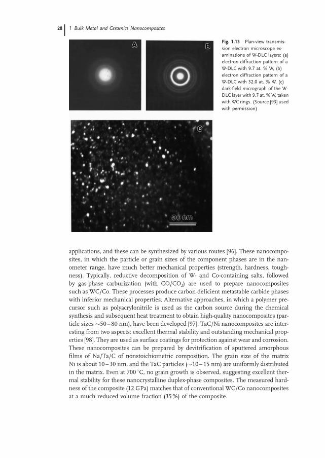
applications, and these can be synthesized by various routes [96]. These nanocompo-sites, in which the particle or grain sizes of the component phases are in the nan-ometer range, have much better mechanical properties (strength, hardness, tough-ness). Typically, reductive decomposition of W- and Co-containing salts, followedby gas-phase carburization (with CO/CO2) are used to prepare nanocompositessuch as WC/Co. These processes produce carbon-deficient metastable carbide phaseswith inferior mechanical properties. Alternative approaches, in which a polymer pre-cursor such as polyacrylonitrile is used as the carbon source during the chemicalsynthesis and subsequent heat treatment to obtain high-quality nanocomposites (par-ticle sizes 50–80 nm), have been developed [97]. TaC/Ni nanocomposites are inter-esting from two aspects: excellent thermal stability and outstanding mechanical prop-erties [98]. They are used as surface coatings for protection against wear and corrosion.These nanocomposites can be prepared by devitrification of sputtered amorphousfilms of Na/Ta/C of nonstoichiometric composition. The grain size of the matrixNi is about 10–30 nm, and the TaC particles (10–15 nm) are uniformly distributedin the matrix. Even at 700 8C, no grain growth is observed, suggesting excellent ther-mal stability for these nanocrystalline duplex-phase composites. The measured hard-ness of the composite (12 GPa) matches that of conventional WC/Co nanocompositesat a much reduced volume fraction (35%) of the composite.
Fig. 1.13 Plan-view transmis-
sion electron microscope ex-
aminations of W-DLC layers: (a)
electron diffraction pattern of a
W-DLC with 9.7 at. % W, (b)
electron diffraction pattern of a
W-DLC with 32.0 at. % W, (c)
dark-field micrograph of the W-
DLC layer with 9.7 at. %W, taken
with WC rings. (Source [93] used
with permission)
1 Bulk Metal and Ceramics Nanocomposites28

Chemical and physical vapor deposition (CVD and PVD, respectively), and laserablation have been used to prepare a variety of superhard nanocomposites made ofnitrides, borides, and carbides. In these systems, the hardness of the nanocompositesignificantly exceeds that given by the rule of mixtures in bulk. For example, the hard-ness of nanocrystalline MnN/a-Si3N4 (M = Ti, W, V, etc.) nanocomposites with theoptimum content of Si3N4 (close to the percolation threshold) reaches 50 GPa,although that of the individual nitrides does not exceed 21 GPa. For a binary solidsolution, such as TiN1-xCx, the hardness increases monotonically with increasing xfrom that of TiN to the that of TiC, following the rule of mixtures. Recently, super-hardness has been achieved in coatings consisting of a hard transition-metal nitrideand a soft metal that does not form thermodynamically stable nitrides, such as nano-crystalline MnN-M’ (M = Ti, Cr, Zr, M’ = Cu, Ni) [99]. However, these systems have lowthermal stability and their hardness decreases upon annealing to 400 8C.The generic concept for the design of novel superhard nanocomposites that are stable
up to high temperatures (1000 8C, which is very important in industrial applications)is based on thermodynamically driven segregation in binary (and ternary) systems.These systems display immiscibility and undergo spinodal decomposition even atsuch temperatures. In these systems, any small local fluctuation in the compositionof themixed phase decreases the free energy of the system, thus leading to spontaneoussegregation and, as a result, a nanocomposite that remains stable against grain orparticle coarsening develops. For many hard coatings (e.g., PVD deposited films,in which the compressive stress is typically 4 to 6 GPa or even greater than 10GPa), the measured enhancement of the apparent hardness and elastic modulus isdue to high biaxial compressive stress. It is important to perform annealing experi-ments in such systems to verify what the real, ‘intrinsic’ hardness of the film is. Theobserved high resistance of superhard nanocomposites to crack formation has beenstudied in terms of conventional fracturemechanics scaled down to dimensions of 1–2nm. An analysis of indentation curves measured on superhard nanocomposites interms of Hertzian elastic response shows that they are indeed strong materials.The stress concentration factor based on nanoscale flaws is low, and therefore, thestress needed to propagate such a small nanocrack is very high. The propagationof such nanocracks in 3D nanocomposites involves much deflection and branchingof the plane of the cracks, which hinder growth of the nanocracks. However, the self-organization of these systems, due to thermodynamically driven spinodal segregation,results in a very low concentration of intrinsic flaws. Thus, the remarkably high re-sistance of these nanocomposites to crack formation can be understood in terms of ahigh threshold for the initiation of larger microcracks, which may lead to their cata-strophic growth.Carbon–carbon nanocomposites: Carbon–carbon composites have received much
attention due to their tremendous potential for applications in the aerospace, automo-bile, and energy industries. This material’s attractive properties include low specificweight, low thermal expansion, high thermal shock resistance, and high strength overlarge temperature ranges. They are usually made with carbon fiber reinforcement,with the matrix being disordered or partially graphitized carbon infiltrated from var-ious resins, pitches, and gaseous (hydrocarbon) precursors. The main limitation of
1.6 Nanocomposites for Hard Coatings 2929

Fig. 1.14 Comparison of the tensile
strength (a), modulus (b), and electrical
resistivity (c) of composite carbon fibers
with 1 and 5 wt. % nanotube loadings with
the corresponding values in unmodified
isotropic pitch fibers. Each data point
represents an average value for strength,
modulus, or resistivity obtained from 12
composite fibers. Standard deviations of
experimental values are strength, 15%;
modulus, 15%; and resistivity, 20%.
(Source [100] used with permission)
1 Bulk Metal and Ceramics Nanocomposites30

these composites is their susceptibility to oxidation, but surface modification or coat-ing of the fibers or addition of appropriate ceramic refractory fillers that shield againstoxygen attack at high temperatures alleviates this problem. The advent of several novelforms of nanocarbons has led to attempts to create nanocomposites with nanocarbon(e.g., nanotubes) components. In a recent experiment, single-walled carbon nanotubes(5% by weight) were uniformly dispersed in an isotropic petroleum pitch matrix tomake nanotube-based carbon nanocomposite fibers (Figure 1.14), with better electri-cal and mechanical properties than isotropic pitch-based carbon fibers [100]. The ten-sile strength increased nearly 100%, and the electrical conductivity increased four-fold. The advent of the new carbon nanostructures suggests that novel carbon–carboncomposites can be prepared with properties far superior to those of conventional car-bon–carbon-fiber-based composites. The challenges lie in achieving proper disper-sion of these nanostructures and tailoring the interfacial strength between the nano-carbons and the matrix.
1.7
Carbon Nanotube-Based Nanocomposites
The mechanical behavior of carbon nanotubes is exciting, since nanotubes are seen asthe ultimate carbon fiber ever made [101]. The most important application of nano-tubes, based on their mechanical properties, will be as reinforcements in compositematerials. Chapter 2 includes a detailed discussion of nanotube-based polymer com-posites; here, we briefly discuss some developments regarding ceramic/metal-matrix-based nanotube composites. The nanotube reinforcements promise to increase thefracture toughness of the composites by absorbing energy through their highly flex-ible elastic behavior during deformation, which will be especially important for nano-tube-based ceramic matrix composites. Possible applications are in lightweight armoror conductive durable ceramic coatings. An increase in fracture toughness on theorder of 10% has been seen in nanotube/nanocrystalline SiC ceramic composite fab-ricated by a hot-pressing method at 2273 K (25 MPa in Ar for 1 h) [102].Nanoscale ceramic powders with carbon nanotubes provide another opportunity for
creating dense ceramic-matrix composites with enhanced mechanical properties. Thestrength and fracture toughness of hot-pressed a-alumina is typically much greaterthan that of conventional grain-size polycrystalline alumina. Addition of carbon nano-tubes to the alumina results in lightweight composites with even greater strength andfracture toughness (Figure 1.15). The mechanical properties of such composites de-pend strongly on the processing method and surface treatment of the carbon nano-tubes. Sintered alumina has high strength, hardness, and fracture toughness. An ex-citing possibility, as well as a processing challenge, is incorporating carbon nanotubesinto an alumina-matrix composite to improve these properties. Alumina (c-phase)matrix composites with 5–20 vol. % MWNT (multiwalled nanotubes) have been fab-ricated [103]. The c-phase alumina powder was transformed to a-alumina (with meanparticles sizes close to 60 nm) during sintering at 1300 8C. The MWNT were lightlyoxidized at 640 8C in air, which removed the disordered carbonaceous material and
1.7 Carbon Nanotube-Based Nanocomposites 3131

Fig. 1.15 (a) Fracture tough-
ness of multiwalled nanotube
(MWNT)/alumina nanocompo-
site compared with that of sin-
tered nanophase alumina. The
inset in (a) shows an indent and
resulting cracks. The micro-
structure of the nanocomposite
is shown in (b). (c) Diametral
strengths of alumina-matrix na-
notube composites hot-pressed
in Ar at 1300 8C and 60MPa for 1
h and containing various
amounts of MWNT. (Source
[103])
1 Bulk Metal and Ceramics Nanocomposites32

made it easier to disperse the nanotubes. The alumina- MWNT mixtures were dis-persed in organic solvents via ultrasound, dried, and then sintered by hot pressingin a graphite die at 1300 8C and a pressure of 60 Mpa. The structures of theMWNT remained the same before and after processing, without any visible degrada-tion. The density of the sintered composites was > 97% of the theoretical density.The diametral strengths of alumina-MWNT composites with different MWNT con-
tents indicate great improvements in fracture toughness with addition of nanotubes.The bulk alumina made from nanoparticles had a strength of 654 MPa, compared totypical strengths of 200–350MPa for sintered bulk alumina, and was even comparableto strengths reported for single-crystal alumina (sapphire) of 350–1000MPa. With theaddition of purified, well-dispersed nanotubes, the strength first increased at 5 and 10vol. % MWNT and then decreased for higher vol. percents of MWNT. The fracturetoughness of bulk alumina and alumina/MWNT composites shows that, for 5 vol.% MWNT composites, the toughness increased by about 25% to about 5.1 MPapm. The toughness values were higher than those reported for single-crystal alumina
(sapphire) and polycrystalline alumina. The hardness of the composite depends onhow well the nanotubes are dispersed in the matrix and how the nanotube surfaceis modified (with functional groups via oxidation) to produce anchors to the ma-trix; for the best value, the Vickers hardness is 20.4 GPa compared to 18.4 GPa forbulk alumina. From the general trends in the results of a few scattered reports inthe literature, the strength and fracture toughness of bulk structures hot-pressedfrom nanophase ceramic powders is much higher than the typical strength and tough-ness of conventional polycrystalline ceramics. The addition of small amounts of na-notubes to nanophase ceramics to form dense nanocomposite improves the diametralstrength and fracture toughness. However, the real improvements occur when thenanotubes are purified and well dispersed in the matrix, so that large aggregatesdo not create macrodefects in the structures, leading to easy fracture and lowerstrength. Vacuum hot pressing also removes entrapped gases in the composite pow-der mixture, preventing formation of residual stresses and reduction of strength.These processing improvements show the great promise of nanophase alumina/MWNT composites for light-weight, high-strength, high-toughness materials andin applications such as impact-resistant body armor.It is widely perceived that carbon nanotubes will allow the construction of compo-
sites with extraordinary properties. Metal-matrix composites, as discussed before, are anew range of advanced materials and normally, the liquid-phase fabrication method isan efficient process because of its simple processing. If carbon nanotubes can remainstable within some suitable high-strength metal matrix, outstanding nanocompositesmay be obtained. The rapid solidification technique allows the extension of alloyinglevels and more refined microstructures, which can lead to enhanced mechanical andphysical properties. In addition, rapid solidification processing may help carbon na-notubes to survive the process because of the controllable melting step, which is themost important issue to be solved in fabricating nanotube-reinforced composites. Ra-pid solidification processing has achieved the successful synthesis of nanotube/Fe80P20 metallic glass nanocomposites [104]. Their properties show that the additionof nanotubes greatly enhances the thermal stability of the glass matrix and increases
1.7 Carbon Nanotube-Based Nanocomposites 3333

the low-temperature electrical resistivity by 70% (Figure 1.16; Table 1.2). The activa-tion energy of crystallization for the nanotube composite is higher than those of boththe Fe80P20 metallic glass and the metallic glass containing 2% carbon. The onsettemperature of crystallization for the nanotube composite is almost 100 K higherthan for the original glass, according to magnetothermal analysis (MTA).
Fig. 1.16 Magnetic susceptibility vs. temperature for various amorphous al-
loys in nonisothermal heat treatments. The temperatures at the end of the first
transition are indicated. The first peak in the plots corresponds to the first
crystallization process. The onset temperature of crystallization for amorphous
Fe/P/2% CNTs is about 100 K higher than that for amorphous Fe/P alloy at the
same heating rate. (Source [105] used with permission)
Tab. 1.2 The onset temperatures at a heating rate of 5 K min-1
and activation energy of crystallization for various amorphous metallic
glass nanocomposite materials containing carbon (C) and Carbon
Nanotubes (CNTs) [105].
Materials Activation energy (kJ mol-1) Onset T (MTA, K)
Fe/P 354.0 0 630
Fe/P/2C 460.9 29.8 709
Fe/P/2CNTs 574.1 35.4 729
1 Bulk Metal and Ceramics Nanocomposites34

1.8
Functional Low-Dimensional Nanocomposites
Recent years have seen a drive towards creating heterogeneous nanostructures, whichcould serve as multifunctional materials and essentially satisfy the definition of func-tional nanocomposites. These stand out from the bulk nanocomposites that are themain subject of this book, but will have important applications as nanoscale sen-sors, electronic and optical nanodevices, nanoprobes, nanoelectromechanical sys-tems, unique reinforcements, and drug-delivery media. These are particularly inter-esting for layered material systems in which atomic layers of different material com-positions (e.g., graphite, dichalcogenides, clays, etc.) can be assembled into differentgeometries on the nanoscale. Some excellent examples, which are described below, areendohedral fullerenes (metal/carbon systems), filled carbon nanotubes, boron/car-bon/nitrogen nanostructures, and nanosize coaxial cables from a wide range oflayered materials.What are the various synthetic strategies for creating such composite nanoscale
structures? One simple, elegant idea is to use infiltration of nanoporous struc-tures, commonly used in bulk composites for creating heterogeneous materials. Atthe nanoscale, this problem is not trivial, especially if the process occurs throughthe infiltration of a liquid or molten phase in which the viscosity of the infiltratingphase is high. A very useful example of such a nanocomposite structure is nanotubesand nanowires built into porous alumina templates. The alumina template can beprepared by anodization of Al metal in acidic solvents, and it is possible to createtemplates with straight, random pores that have diameters of 20–50 nm and are sev-eral micrometers long, running through the thickness of the alumina template [106].Once the templates with pores are prepared, they can be filled (via electrochemicaldeposition) with nanowires (such as Au, Co, etc.; Figure 1.17) by changing the elec-trochemical conditions and introducing metal-containing solvents into the electrolyte[107]. The structure of the metal wires can be tailored (amorphous or crystalline) bychanging the electrochemical deposition conditions. The distinct difference betweennanowires created by other techniques and by template-based synthesis is that thelatter technique offers the possibility of creating well-separated individual nanowireswith adjustable diameters. Structures such as carbon nanotubes can also be depositedin the pores defined by such templates, by infiltration of gaseous hydrocarbon precur-sors (e.g., acetylene, benzene) and subsequent annealing [108]. Electrochemical tech-niques for materials processing (from highly anisotropic wires inside porous tem-plates to particle-dispersed thin-film nanocomposites) provide a powerful alternativetechnique to vapor phase deposition and solid state reaction for the synthesis of na-nomaterials and nanocomposites [109]. Their main advantage is control of the processso as to modulate dimensions and compositions. Their disadvantages are mainly poorcrystallinity (being a low-temperature deposition process) and contamination with im-purities from the electrochemical baths.
1.8 Functional Low-Dimensional Nanocomposites 3535

1.8.1
Encapsulated Composite Nanosystems
Here, we describe the creation and characterization of composite carbon/metal-basednanostructures (systems consisting of combinations of a layered material and a solidphase, which have been studied by several groups in recent years). These are uniquenanocomposite systems with promise for many interesting applications.Graphite-encapsulated metal/ceramic structures are interesting systems, and the
generation of metal/carbon nanosystems requires knowledge of the interactions ofmetal atoms and the graphite lattice. The experimental study of the behavior of indi-vidual metal atoms in a graphitic environment is difficult and has been successful inonly a few cases. In 1993, Ruoff et al. [110] performed carbon-arc discharge experi-ments using C anodes filled with metals and metal carbides and obtained carbon na-notubes and polyhedral carbon nanoparticles that contained both encapsulated metalsand metal carbides. Polyhedral graphitic particles generally contain a hollow core,which is given shape by the outer faceting of the particle, and metal nanoparticlescan easily fill these cores during formation (Figure 1.18). Metal surfaces are expectedto act as nucleation sites for graphitic carbon to surround. The expected tendency ofpreexisting graphitic filaments is to wrap around metallic nanocrystallites and close by
Fig. 1.17 Nanowires grown in alumina templates. Top schematic shows how pores in a
straight-pore anodic alumina template are filled with metal by electrodeposition. Scanning
electron micrograph of Co nanowire-filled template is shown in lower image; an individual
nanowire removed from the template is shown (right). (Courtesy Prof. Mamoun Mu-
hammed, The Royal Institute of Technology Stockholm, Sweden)
1 Bulk Metal and Ceramics Nanocomposites36

saturating all carbon dangling bonds. The properties of encapsulated metal crystalshave been the subject of many experimental studies [111]. Graphite-coated ferromag-netic metal crystals should show a reduced magnetic coupling that depends on thethickness of the graphite shell [112], with potential applications in magnetic recordingmedia. Guerret-Piecourt et al. [113] sought general principles relating to the nature andstructure of the fillingmaterials, for efficient filling of nanotubes made via the electric-arc method (Figure 1.19). Several metals and/or their compounds have been encap-sulated in carbon cages and studied; e.g., Ti, Cr, Fe, Co, Ni, Cu, Zn, Mo, Pd, Sn, Ta, W,Gd, Dy, and Yb. In later experiments, the authors also managed to fill hollow carbonnanostructures with semiconducting structures such as Se, S, Sb, and Ge by similarprocesses [114]. S, present as impurity in the carbon, was later reported to play a majorrole in the effective formation of the filled carbon nanotube/nanoparticle structures.The above technique has made it possible to encapsulate a large number of carbidesnanocystallites [115, 116] (LaC2, YC2, CeC2, Gd2C3, TiC, V4C3, ZrC, TaC, MoC, NbC,HfC). With pure metals such as Fe, Ni, or Co, which strongly interact with carbon,encapsulating nanowires inside nanotubes is challenging. However, experiments have
Fig. 1.18 (a) Schematic of an endohedral fullerene. Structural model of a La atom in C82
fullerene (b) Encapsulated nanoparticle of lanthanum carbide inside a carbon polyhedral
particle (approximately 50 nm in diameter) produced in an arc discharge with a composite
carbon/La electrode. (c) Encapsulated nanoparticles of metals (Fe, Co, Au) in spherical
graphitic layers (carbon onions). These structures were produced by electron irradiation of
carbon soot containing the metal species
1.8 Functional Low-Dimensional Nanocomposites 3737

shown that onion-like nanoparticles of metal-containing carbon clusters can be pro-duced relatively easily with the arc method. Here, the metal or metal carbide encap-sulate is protected by the C layer coating, which effectively insulates the magneticmetal particles from oxidization upon exposure to the environment and retains itsmagnetic properties. It is noteworthy that high melting point refractory metal carbidessuch as TaC, NbC, and MoC, which exhibit superconducting transitions at low tem-peratures, have been inserted into nanotubes and graphitic nanoparticles [117]. Bulkmagnetic susceptibility measurements of encapsulated TaC, MoC, and NbC revealeddiamagnetic responses and superconducting transitions between 10 K and 14 K, re-spectively. The structure and state of these encapsulated nanostructures affects theirphysical properties; for example, a shrinkage in the lattice parameters for the (fcc) MoCencapsulated structure appears to decrease the Tc by 3.8 K.Magnetic alloy (e.g., FeCo) nanoparticles encapsulated in carbon layers can also be
made in radio frequency (RF) torch reactors, and acetylene was used to generate a largenumber of carbon-coated particles [118]. The carbon lamination provides several func-tions for these nanoparticles that have low magnetocrystalline anisotropy and largesaturation magnetization (making them valuable as soft magnetic materials). Thesefunctions include oxidation protection, prevention of coarsening and particle coales-cence during growth, shielding interparticle magnetic interactions, and even reducingeddy current losses in high frequency environments. This technique can readily pro-duce particle sizes anywhere from 5 to 50 nm. Other techniques, such as the tungstenarc, blown arc, or electric arc generation, can be used to create encapsulated nanos-tructures of similar dimensions.The first experiments on filling of nanotubes date to 1993, where the filling was
done via capillary forces, which pushed molten metals and compounds into the cav-ities of nanotubes during oxidative opening of their tips (Figure 1.20) [119]. Since then,the most efficient filling of hollow nanostructures to create heterogeneous nanoma-terial systems has been achieved by chemical treatment. Tsang et al. [120] filled larger
Fig. 1.19 (a) High-resolution transmission electron micrograph of a Mn metal-filled
carbon nanotube made by electric arc discharge with electrodes of carbon filled with Mn
(b) Encapsulated nanotubes with Fe carbides, formed during a chemical vapor deposition
process involving hydrocarbon and metalorganic precursors
1 Bulk Metal and Ceramics Nanocomposites38

multi-walled carbon nanotubes oxidatively by opening the ends in nitric acid and thenfilling with solutions containingmetal oxides (e.g., oxides of Ni, Co, Fe, U,Mo, Sn, Nd,Sm, Eu, La, Ce, Pr, Y, Zr, Cd) using capillary force. They were then dried to formencapsulated solid materials inside the nanotube cavities. Several other material sys-tems such as Pd, Ag, Au, AuCl, proteins, and enzymes have been introduced intonanotubes with this method. Recently it was reported that single-walled nanotubes(SWNTs) can be opened selectively and filled by wet-chemistry techniques [121]. Treat-ment with concentrated HCl leads to the selective opening of SWNTs at their tips, andforeign materials may be drawn in, in a similar fashion as MWNTs; the much smaller(1 nm) cavities in SWNT make the filling more challenging. Usually, the nanowiresformed inside the nanotubes are single crystals. Alternative strategies to fill nanotubecavities with materials have been explored. For example, exposing SWNT nanotubesfilled with AgCl/AgBr to light or an electron beam can reduce the encapsulated com-pounds, resulting in extremely small Ag nanowires [122]. Similarly, constrained che-mical reactions within narrow channels can be used to create and characterize nano-wire structures of many materials. These promise to be ideal structures for studying1D properties (electrical, thermal, optical) in materials for applications such as quan-tum wires and magnetic storage arrays. Characterization of these structures is oftenchallenging, but recent progress in highly spatially resolved microscopy and spectro-scopy techniques have enabled researchers to carefully study the structure–propertyrelationships in confined nanocomposite wires. SWNTs containing fullerenes in theirinner hollow are another unique form of nanocomposite structure with interestingelectronic properties. C60 insertion into SWNT could occur during their formationin the arc or laser process. Very recently, researchers have managed to introduceC60 inside SWNTs in high yield (Figure 1.21) by thermally annealing C60 powders
Fig. 1.20 Top: (a) High-resolu-
tion transmission electron mi-
crographofaKIcrystal ina1.4-nm
diameter SWNT, (b) its structural
representation. Encapsulation of
halidesandothermaterialswithin
SWNTs enables the study of 1D
crystal structures formed on the
smallest scale possible. Bottom:
(c, d) Schematic of a filledMWNT
and a corresponding transmis-
sion electron micrograph of Pb
oxide nanowire-filled nanotube,
formed by capillary filling of the
molten material inside nanotube
cavities. In(d)thehorizontal lines
indicate graphite planes which
have a separation of 0.34 nm.
(Source, top image and sche-
matic [233] used with permis-
sion)
1.8 Functional Low-Dimensional Nanocomposites 3939

over SWNTs above 600 8C under vacuum [123]. This class of hybrid materials mayform the basis of functional devices for applications in electronics, biomedicine,and microelectromechanical systems. Similarly, endohedral fullerenes [124] (or full-erenes containing single or multiple metal atoms, which in their own right can beconsidered novel nanocomposite systems; e.g., La2@C80, Gd@C82, etc.) have beenintroduced into SWNTs through the vapor phase. These structures are breakingnew ground because creation of nanocomposite structures with discrete atomic spe-cies in their cores are resulting in the discovery of novel properties of 1D nanoscalematerials.Recent theoretical studies suggest that the presence of a metal nanowire inside a
nanotube greatly alters the mechanical properties of the nanotube, for example, sup-pressing tube-buckling instability. Increasing tube diameter increases the bendingstrength; however, in contrast to hollow tubes, there is no decrease in the maximumdeflection before buckling. Analysis of the principal bending vibrational mode shows alowering of the frequency, associated with increased tube inertia. Remarkably, metal-filled tubes exhibit strong damping, whereas unfilled single-walled and multi-walledtubes show no damping of oscillations (Figure 1.22). Simulations of multi-walled na-notubes revealed the lack of damping behavior; the dissipation of the mechanical en-ergy is intrinsically associated with tube filling by a dissimilar material [125]. Thesestudies demonstrated the benefits of filling tubes with solids for modifying the bend-ing strength and flexibility, suggesting implications for nanotube-based elements inmicromechanical devices or nanoprobes. Experimental studies on these unique 1Dnanocomposite systems are eagerly awaited, since a variety of them have alreadybeen fabricated.Condensed-phase electrolytic processing provides an alternative way to fabricate
nanotubes with or without encapsulated metals. The technique involves passage ofan electric current through graphite electrodes immersed in molten mixtures of ionicsalts (e.g., LiCl, SnCl2) under inert gas atmospheres [126]. The graphite crucible anode
Fig. 1.21 (a) Transmission
electron micrograph of a
La2@C80@SWNT assembly.
Each C80 molecule appears as a
dark circle, and the SWNT
(1.4 nm diameter) itself appears
as two parallel lines. (b) Effect of
inserted Gd metallofullerenes
(GdMFs) on the topography and
band structure of a single-walled
nanotube (SWNT). The illustra-
tion of a (11,9) GdMF-SWNT.
Schematic representation of es-
timated modulation of conduc-
tion (Ec) and valence (Ev) band
edges is also shown. (Source:
top image [234], bottom part
[235] used with permission)
1 Bulk Metal and Ceramics Nanocomposites40

contains the electrolyte salt, which is heated by an external furnace. When the saltmixture melts, the cathode (graphite rod) is immersed in the electrolyte. During elec-trolysis, the graphite electrode interacts with the molten electrolyte, forming nanos-tructures. If pure LiCl is used as the electrolyte, the carbonaceous material formedconsists of tangled carbon nanotubes, some of which contain the carbide of thesalt (i.e., LiC). Adding small amounts of low-melting metals such as Sn, Pb, andBi to the electrolyte forms nanowires of the respective metals. The formation of car-bide nanowires is based on the reduction of metal ions on the graphite cathode surfaceand intercalation of the Li between the graphite layers, followed by the formation ofLi2C2. Carbon then precipitates in the form of nanotubes. When Sn, Pb, and Bi areadded to the electrolyte, the cations derived from these metals are discharged at theelectrode surfaces by the electrons provided by oxidation of the carbide. This ultimatelyforms metallic nanowires surrounded by graphitic sheets in the nanotube form. Thistechnique has also generated carbon-encapsulated Sn/Pb nanowires [127].Pyrolysis of hydrocarbons over metal catalysts at elevated temperatures also pro-
duces filamentous structures containing metal and carbon [128]. If the catalyst con-centrations are high (>10–20%), encapsulation of the metal catalysts can producenanowire composites. Pyrolysis of organic compounds or other carbon sourcessuch as C60 in the presence of transition metal species (e.g., metallorganics such
Fig. 1.22 Damping in pure vs.
metal-filled nanotubes, simula-
tion results. Top: bending of
filled nanotubes; filling makes
the nanotubes stiffer to bending
and buckling. Oscillatory fre-
quency (fo) of vibration, as a
function of tube diameter for
filled and hollow tubes as func-
tion of tube diameter. The filled
nanotube composite structures
show high damping during vi-
brations. (Source [125])
1.8 Functional Low-Dimensional Nanocomposites 4141

as ferrocene) leads to nanotubes containing these metals or their alloys [129]. Metalnanowires over carbon structures can also be prepared via substitution. Recent worksuggests that suspending SWNTs and exposing them to metal vapor can be used tofabricate nanowires of Pt, Au, Ti, etc. Hollow nanotubes of the metal are formedaround nanotube templates [130]. Composite nanotube-based nanocomposites con-sisting of nanotubes and other materials can also be created by coating nanotube tem-plates by capillary effects. Nanoscale skins of layered oxides such as V2O5 can be uni-formly coated onto nanotube surfaces [131] (Figure 1.23). It is also possible to createcomposite nanowire systems by CVD techniques, in which individual layers of lami-nated materials such as MoS2 andWS2 are coated onto multi-walled carbon nanotubes[132]. The electronic properties of these coated tubes are dominated by their outermostshells (oxides or sulfides, which are generally semiconducting or insulating). How-ever, the inner tube structure (carbon nanotubes) may dominate the mechanical prop-erties. In this way, it will be possible to tailor both the mechanical and electronic prop-erties of these 1D systems. Physical property characterization of these nanocompositesystems is challenging, but much excitement exists about uncovering a rich range ofproperties inherent to these nanoscale multiphase systems.Multiple-phase nanowires, constituting different structures along the wire length,
may also become important in future nanotechnology. The advantage here will be theability to form controlled junctions, which could have semiconducting properties(metal–semiconductor junctions), novel deformation behavior (whereby toughnessmay be increased when they are used as reinforcements), photoluminescence (if
Fig. 1.23 Scanning electron micrograph showing
the fibrous structure of carbon nanotube/V2O5
nanocomposite. The individual nanotubes (seen as
tiny filaments) are finely coated with subnanometer
layers of the oxide, uniformly on the surface,
modifying the nanotube surface properties. The
structure was made by mixing nanotubes and oxide
powder and annealing.
Fig. 1.24 High resolution transmission electron micro-
graph of a heterojunction formed between an Fe nanowire
and a multiwalled carbon nanotube. The structure was
formed in the vapor phase during pyrolysis of hydrocarbon
and ferrocene. Similar structures can also be made by step-
wise electrodeposition inside alumina nanoporous mem-
branes.
1 Bulk Metal and Ceramics Nanocomposites42

phases are semiconducting with distinct n- or p- character), or thermoelectric-junctionproperties. Carbon nanotube–metal junctions have been made by using excess cat-alyst (Fe) in the chemical vapor deposition process or by electrochemical deposition inporous alumina templates (Figure 1.24) [133, 134], but the properties of thesemultiple-phase nanowires have not been evaluated. Controlled solid-state reactions have beenused to form heteronanowires of single-walled carbon nanotubes and nanorods ofsilicon carbide and transition-metal carbides (TiC) [135]. The reactions are carriedout via contact annealing with a metal (or Si) solid surface and nanostructuressuch as nanotubes. The structures created are some of the smallest heterojunctionsthat have ever been made and will play a large role in the fabrication of future hybridnanodevices. Similarly, techniques such as laser ablation have been used to form coax-ial cables containing heterocompositional layers. For example, high resolution trans-mission electron microscopy and spatially resolved electron energy loss spectroscopyhave characterized wires that consist of b-silicon carbide sheathed inside amorphoussilicon oxide surrounded by graphitic shells made of C or h-BN [136] (Figure 1.25).These coaxial nanocables of semiconductor-insulator-metal/semiconductor structurescould find applications in nanoscale electronics. The formation of such multiple-layernanocable structures is challenging and has to be controlled through the self-assemblyof various elemental and molecular species in the vapor phase during relatively shortgrowth times, and the directed assembly of such complex structures is one of the mostcrucial steps in the creation of useful low-dimensional functional nanocompositestructures.Recent work has also demonstrated that semiconductor nanowires can be control-
lably grown in cross-bar array architectures, and, if the crossing nanowires can bedoped into n- or p- type, then light emission can result at the crossing junctionswhen a voltage is applied across the wires. High-temperature laser-assisted deposition
Fig. 1.25 Transmission electron micrograph of
nanocable structure (SiC/SiO2/BN/C) showing a
crystalline core and an amorphous layer. Inset: the
selected area diffraction pattern indicates that the
crystalline core is b-phase SiC with the <110> axis
parallel to the electron beam. Bottom: profiles of B
and C across half a nanocable from EELS mea-
surements, showing a phase separation of graphite
and BN layers. (Source [136] used with permission)
1.8 Functional Low-Dimensional Nanocomposites 4343

has been used to grow single-crystal indium phosphide (InP) nanowires using catalyticgold particles [137], either in p-doped or n-doped form. Superlattice nanowires can alsobe made with alternating blocks of different semiconducting materials (e.g., Si andSiGe) on a single wire [138]. A hybrid pulsed-laser ablation/chemical vapor depositionmethod can be used to custom-create various heterostructures on individual nano-wires. These structures systematically contain junctions and interfaces between themultiple blocks present in the same wire, enabling them to be useful in miniaturizedtransistors, LEDs, and lasers.
1.8.2
Applications of Nanocomposite Wires
Of several applications proposed for composite nanowire structures, only one is dis-cussed here. Magnetic recording exploits the hysteresis behavior of ferromagneticmaterials: the residual magnetization of a tape or magnetic disc is a record of themaximum field intensity the material experienced with respect to the magnitudeand direction of the applied field. For long-term storage, usable magnetic materialsshould have a reasonably high coercivity, because external magnetic fields shouldnot alter the magnetization. However, the coercive force should not be too large ifthe medium is to be reusable, since the magnetic fields used during recording shouldbe capable of remagnetizing the material for new data recording. Recently, featuresizes on magnetic disks made using complicated e-beam lithography protocolshave shrunk to the sub-100 nm range [139]. Ferromagnetic Fe nanowires could pro-vide an ideal system for recording, but the tendency to oxidize is strong in nanoscalemetallic systems. The encapsulation of Fe nanowires within carbon nanotubes willassure that the metal is maintained in the reduced state, due to the protective C coat-ing. These encapsulated nanowires exhibit magnetic coercivities larger than thoseassociated with pure Ni and Co nanowires [140]. The coercive field decreases linearlywith increasing temperature, revealing the presence of anisotropy. The small size,anisotropy, and the single (isolated) domain nature of the encapsulated Fe crystalsappear to be responsible for this enhanced coercivity. The magnetic properties of en-capsulated Fe nanowires do not degrade with time, because they are sealed within thegraphitic tubes. These nanowire arrays may have significant potential inmagnetic datastorage device applications (e.g., quantized magnetic disks) due to their size and ani-sotropic behavior, with the possibility of drastically increasing the attainable recordingdensity. Film structures of this kind, based on single-domain elements, exhibit thebest available storage densities (e.g., 65 Gb in-2) [141]. The type of magnetic nanocom-posite particles should also find applications in the fabrication of fine-particle magnetsfor use in magnetic inks and as toners in xerography.
1 Bulk Metal and Ceramics Nanocomposites44

1.8.3
Applications of Nanocomposite Particles
Several strategies are being pursued for creating nanoparticles containing multipleshell structures (for multifunctionality), with each shell composed of different materi-als. Template-based approaches are effective in this situation, for which an inner re-movable template particle (silica, polymer beads) can be used to coat shells of othermaterials (e.g., a metal) via multi-step colloidal or vapor-phase assembly and can laterbe easily removed to create empty shells. These could even be filled with differentmaterials to produce multiple-shell composites [142]. Creating uniform coatings onparticle templates by colloidal self-assembly is based on the concept of self-assembledorganic molecular species. The two ends of the molecules to be joined have specificfunctional groups (e.g.. thiols, amines, carboxylic groups) that can be targeted for spe-cific interactions with the template and the clusters that are used to make the coatings.Uniform, dense packing of the molecules around the templates leads to close packing
Fig. 1.26 Fabrication of multilayer nanoparticle
structures by colloidal synthesis. Top: micrograph of
silica spheres being continually coated with gold
nanoparticles until a uniform coating is produced.
The process of attachment of gold particles (shown
in the schematic below) occurs via connectors of
self-assembled monolayers of bifunctional organic
molecules (e.g., mercaptopropyltrimethoxysilane).
Multiple-layer structures can be fabricated by col-
loidal assembly techniques. (Courtesy Prof. Ma-
moun Muhammed)
1.8 Functional Low-Dimensional Nanocomposites 4545

of the clusters that form a porous but space-filled shell around the template (Figure1.26). Noninteracting metal-coated magnetic particles (SiO2/Au, Fe3O4/Au, NiO/Co,etc.) or coated semiconducting particles (PbS/CdS) are examples of such compositeparticle structures. These structures can have applications in magnetic recording, asmultilayered catalyst materials, or in drug delivery. In such applications of drug de-livery systems [143], for which a biocompatible outer layer and a drug-containing innercore are necessary, the multilayered particle approach will be crucial. As an alternativeto colloidal templating, structures such as PbS-coated CdS nanocomposite particles (afew nanometers in diameter) may be synthesized by ion displacement in inverse mi-croemulsions and could be useful in nonlinear optical applications. The observed largerefractive nonlinearity in these nanocomposite particles may be attributed to the op-tical Stark effect and to strong interfacial and internanoparticle interactions.
1.9
Inorganic Nanocomposites for Optical Applications
Nonlinear optical effects, such as nonlinear optical absorption and second- and third-order optical nonlinearities, can be used to make optical limiters, optical modulators,etc. Although many organic materials have high optical absorption and nonlinearity,their thermal and optical stabilities are poor. Often, it helps to create hybrids or com-posites (organic/inorganic, inorganic/inorganic) that have acceptable optical proper-ties and stability. Quantum-confined nanoparticles have been extensively used in thefabrication of such composites because of their novel optical and electronic properties.The organic-matrix nanocomposites for optical applications are described in chapter 2,which briefly discusses some of the organic materials that contain dispersed nanopar-ticles in various hosts.Recent advances in controlling the fabrication and dispersion of semiconductor
nanoparticles in polymer and ceramic matrices have suggested possible uses forsuch nanocomposites in optical applications. A good example of an optically func-tional ceramic nanocomposite is GaAs nanocrystals embedded in SiO2 matrix. Theinterest in the novel optical properties of semiconductor nanocrystals [144] has re-sulted in strategies to package them as nanocomposites. A variety of techniques,such as colloidal synthesis, self-assembly, and electrochemistry, can be used to pro-duce the semiconductor nanoparticles; however, ion coimplantation (Ga+, As+) is anefficient way of creating well-dispersed nanocomposite materials (e.g., GaAs/SiO2)[145]. Typically, the ions are implanted at fluxes of 1016 cm-2 into 100 nm silica filmson Si substrates and annealed at appropriate temperatures to create nanocrystals ofGaAs (several nanometers in size) in the matrix (Figure 1.27). Photoluminescencestudies show an efficient, broad luminescence band in the visible and near-infraredspectral regions due to quantum confinement in GaAs nanocrystals and defect statesin SiO2.Nanoparticles in matrices have interesting photoluminescence properties, due to
the effects of quantum confinement on their optical properties. Indirect band semi-conductors such as Si and Ge have very poor luminescence efficiency (hence, efficient
1 Bulk Metal and Ceramics Nanocomposites46

light emitters cannot be fabricated directly from them), because the band center tran-sition is optically forbidden. But, by making the particle sizes smaller than the excitonBohr radius (4.9 nm for Si, 24.3 nm for Ge), the resulting confinement produces anincrease in oscillator strength, shifting the luminescence to higher energies; this al-lows tailoring novel optical materials, which are otherwise impossible. To take fulladvantage of the particle size effect, the particles must be separated, and the best pos-sible way of accomplishing this is to disperse the particles in a matrix. Understandingandminimizing the interaction of the hostmatrix and the particles that create interfacestates are crucial to many of the optical applications. Embedding nanoparticles in dif-ferent matrices and studying the optical properties provides a way to decipher interfaceeffects. Ge quantum dots have been studied in various hosts, and one way to minimizehost interaction is to embed them in oxygen-free environments, such as AlN; AlN/Gemultilayer structures deposited by pulsed-laser deposition show a blue-shifted photo-luminescence peak [146]. Similarly, indium oxide (InO) nanoparticles dispersed (bysolvent-phase impregnation) within the pores of mesoporous silica (prepared by sol–gel technique) show multiple photoluminescence peaks related to the size and struc-ture of the particles [147]. Amorphous InO particles (<6 nm) show a photolumines-cence peak that is down-shifted compared to slightly larger crystalline particles. Forlarger aggregates of InO particles, no photoluminescence is observed. Si nanoparticlesthemselves are interesting from the point of view of photoluminescence, and porousSi, which contains small particle domains, has been studied in great detail. The pro-blem with porous Si is the structural nonuniformity, lack of reproducibility in emis-sion and aging, and environmental degradation problems. Incorporating light-emit-ting Si structures in a matrix that is chemically inert and has a wide band gap suitablefor quantum confinement can overcome this problem. Nanocomposites of Si nano-particles (5 nm) embedded in polycrystalline diamond matrix have been prepared
Fig. 1.27 Transmission electron micrograph, left,
GaAs nanocrystals embedded inside SiO2 glass
matrix. Sequential ion implantation followed by
thermal annealing was used to form GaAs nano-
crystals in SiO2 films. Right, efficient, broad
photoluminescence band observed in the red and
near infrared spectral regions. The efficient lumi-
nescence is attributed to both quantum confine-
ment states in GaAs nanocrystals and defects in
SiO2. (Source [145] used with permission)
1.9 Inorganic Nanocomposites for Optical Applications 4747

and studied. The room temperature photoluminescence behavior of such materials inthe 1.6–2.5 eV range shows a strong increase in emission efficiency from the Si na-nostructures. The studies conducted on this nanocomposite reveal that selecting thesize of the embedded Si particlesmakes it possible to tune the luminescence frequencyin the yellow–green spectral region.Nanocomposites of nanosized metal particles in transparent dielectrics can also be
applied as nonlinear optical materials in photonic devices. These materials are char-acterized by large third-order optical nonlinearity (v3) and fast response times, whichare important for device applications such as optical computing, real time holography,and phase conjugators. To incorporate metal nanoparticles into dielectrics, severaltechniques such as ion implantation, sol–gel techniques, and sputtering can be em-ployed. It is even possible to prepare graded layers of metal nanoparticle distributions(with different particle sizes and interparticle separations) by implantation, and thesestructures can be carefully tailored to produce interacting and noninteracting nano-particle layers that produce different optical response in the plasma resonance fre-quencies. Several of these composite systems have been studied, for example, Au/SiO2, Ag/SiO2, Au/Al2O3, Au/TiO2 with metal concentrations varying from 15%–60%, for nonlinearity and plasma resonance frequency shifts. High values of suscept-ibilities (v3 6 10-7 esu, compared to low values of 10-12–10-11 esu for glass) havebeen reported for composites containing an optimized fraction of the metal compo-nent [148, 149]. Groups II–VI semiconducting nanocrystals (e.g., CdS) prepared inglass hosts have been studied in great detail, because of their large optical nonlinearresponse and small carrier lifetimes. Enhancement of carrier recombination rates isobserved in nanocrystals with large surface-to-volume ratios, and the enhancementresults from increases in the density of surface states and fast surface recombinationand capture due to multiphoton emission. Surface recombination in nanocrystals em-bedded in glass matrices exhibits thermally activated nonradiative recombination,which is enhanced at reduced particle size. The semiconductor/glass interfaces inthe composites may give rise to deep traps responsible for photoactive phenomena.In recent years, nanoparticles have been used to make transparent nanocomposite
structures having high refractive indices. Polymers containing inorganic particles in arange of 1–100 nm (nanocomposites) are interesting in this regard. In contrast tocomposites having particles in the micron size range, nanocomposites do not scatterlight and are interesting for optical applications. Preparation of nanocomposites withrefractive indices over the entire range of <1 to >3, which is by far the lowest andhighest ever achieved for a polymer composite, has been possible. Transparent poly-meric materials can be coated with surface layers (100 nm thick) of UV-absorbingnanocomposites to inhibit degradation of the polymer by UV light [150]. High-refrac-tive-index transparent materials are mainly used for improving the optical couplingefficiencies in photonic devices. The refractive indices of polymers vary between1.3 and 1.7, those for inorganic semiconductors vary between 2 and 5, and forhigh bandgap semiconductors this value is <3. The technological challenge in creat-ing near-transparent high-refractive-index organic/inorganic nanocomposites lies inthe creation of nanoparticles in the size range 20–40 nm, to produce high-refrac-tive-index nanoparticles with low absorption coefficients in the visible range. Exam-
1 Bulk Metal and Ceramics Nanocomposites48

ples of such composites are PbS, InP, GaP, Ge, and Si particles in a gelatin matrix. Theparticle sizes, as well as the loading fraction of the particles, affect the refractive indexand absorption coefficient. Very small particles show reduced refractive index. Buttypically there is a critical size above which the value of refractive index reachesthe bulk value (for PbS this is 25 nm). Hence, to obtain predictable values of refrac-tive index, it is important to have good dispersion of particles. The particles useful forcreating these nanocomposites can be produced through a variety of techniques, ran-ging from mechanical attrition [151] (followed by centrifugation to obtain near-uni-form Si particles) to colloidal processing. Nanocomposites can then be prepared bymixing and spin coating (or casting) aqueous solutions of gelatin with suspensionof nanoparticles in appropriate organic solvents.
1.10
Inorganic Nanocomposites for Electrical Applications
The incorporation of particles of a nonpiezoelectric phase into a piezo material isunlikely to improve properties such as the strain per unit field or the charge perunit force, but the dielectric loss of the nanocomposite material under high alternat-ing electric fields is an interesting issue. High-drive electrical applications are oftenrestricted by reduced efficiency, due to heating caused by the large dielectric loss athigh fields. A clear distinction has been shown between weak and strong field behaviorin materials such as BaTiO3. Above a critical field level, the dielectric constant anddielectric loss increase dramatically, due to hysteretic domain wall motion and theresultant reorientation by spontaneous polarization. It is possible that incorporatingnanosized particles (SiC of small volume percentages, 2.5%) into an electroceramicmatrix (BaTiO3) may hinder domain wall motion sufficiently to reduce dielectric lossesat high fields [152]. Accordingly, the microstructure requires the particles to be situ-ated intragranularly. This concept is similar to that used in the development of hardferromagnetic materials, for which heat treatment is used to produce a fine dispersionof particles within the microstructure, which increases the resistance to domain wallmotion. In addition to the possible effect of the particles on piezoelectric properties,additional issues that require examination include the influence of any secondaryphases produced by solid-state reactions between the matrix and nanoparticles; ina BaTiO3/SiC system, heat treatment and hot pressing can form new phases suchas Ba2TiSi2O8. When such reaction phases are present in the composite, the permit-tivity of the system is lowered. Addition of silicon carbide leads to a change in themicrostructure of the material and a decrease in grain size. This outcome hasbeen reported in structural systems, which show corresponding improvements inmechanical properties. In addition, the fracture mode was transformed from transgra-nular for monolithic BaTiO3 to intergranular for the nanocomposite. Many studieshave been undertaken to fabricate piezoelectric particle-dispersed ceramic nanocom-posites from other materials: Pb(Zr, Ti)O3 nanocomposites have been prepared fromhigh-purity PZT powder and small amounts of oxides (Al2O3, MgO, etc.) [153]. Smalladditions of a second phase improve the mechanical properties, such as hardness and
1.10 Inorganic Nanocomposites for Electrical Applications 4949

fracture toughness, of the PZT. The nanocomposite’s reduced grain size during pro-cessing with the second phase is responsible for the improved mechanical properties.The piezoelectric properties of these composites remain essentially unchanged,although for the MgO composites, the electromechanical coupling factor (which isimportant for actuator applications) becomes larger.Nanocomposites can also be useful for such applications as electrical contact ma-
terials, particularly to replace the toxic Ag/CdO contacts being used now. The reactivemilling process has been used for manufacturing Ag/SnO2 nanocomposites. A high-energy ball mill controls the reaction to obtain nanosized SnO2 particles in an Agmatrix [154]. Then this powder is hot pressed into electrical contacts with superiorerosion resistance and good thermal and electrical conductivity. Such cermet-like na-nocomposites (in different configurations) have applications in other areas, like sen-sors. Many reports have appeared on gas-sensing technologies based on the measure-ment of changes in the electrical resistances ofmetal oxides (such as SnO2, TiO2) as theenvironment is changed. The sensitivity and selectivity of these metal oxide sensorscan be affected by deposition of discontinuous metal films on their surface. Metalssuch as Pd, Pt, etc. have been used as surface activators. Similarly, incorporating metalclusters into bulk oxides to form nanocomposites also makes it possible to tailor theeffective bulk electrical response of sensor materials. This incorporation allows therange of resistivity changes caused by changes in the carrier concentration at the sur-face or bulk of the metal oxide sensor material to be altered.Although ceramic/metal composites are exciting mostly due to improved mechan-
ical properties, the temperature-dependent electrical behavior of metal in ceramic na-nocomposites is quite interesting [155]. As examples, Ag and Pb particles have beenprepared in silica gels by electrochemical methods. DC electrical characterization ofthese materials shows surprising changes from semiconducting to metallic behavioras a function of temperature and depending on particle size. The electron conductionmechanism in these nanocomposites is complicated but, in general, occurs via twoconductionmechanisms: electron tunneling betweenmetal particles andmetallic con-duction due to the presence of metal percolated paths. The particle size and micro-structure of the composite can be changed to adjust these properties [156]. The variableconductivity of these composites can be used in applications, such as electromagneticinduction shielding.
Percolation Effects and Transport Phenomena in Composite Systems
To understand nanocomposites in terms of conduction processes, we need a basicunderstanding of the bulk materials as well as of the composite filler. This is wherecertain issues arise. When dealing with organic or inorganic insulators and semicon-ductors, we may rely on a form of charge transport through the medium in terms ofvariable range-hopping conductivity when we add fillers to the system [157]. However,the conductivity is determined by the dominant charge carrier, because the carrier’smobility in hopping from one site to the next is the dominating feature of the con-duction mechanism. A detailed study of hopping and its effect on conductivity hasbeen summarized earlier [158, 159].
1 Bulk Metal and Ceramics Nanocomposites50

For metal filler systems in insulating matrices, the dominating feature is the type offiller, with particular regard for its size and shape [160]. Changing the electricaltransport properties of these insulators with nanosize fillers is necessary, becausewe want to retain the innate properties that make the insulators useful. We alsowant to induce electronic properties that allow us to make quantitative determinationswithout altering the chemical and/or physical nature of the dominant medium (in-sulator). For the simple percolative effect, we must look at the insulating/metallicmix. In general, for bulk transport properties, the conductivity follows a power lawbehavior:
r ¼ r0ðp pcÞt ðfor t ¼ 2Þ ð1Þ
where r denotes the conductivity and p represents the mass fraction [161]. In the past,this behavior has been shown to agree with 3D behavior, by Monte-Carlo simulationsfor thick films [162].We do not deal with this behavior in detail here, except to note thatthe study of superconductivity in percolating films is relevant for the interpretation ofcritical temperature and heat capacity data [163]. A more detailed application of per-colation theory deals with the effect of varying the number of interconnections presentin a random system [164]. Fourier et al. [165] proposed a model in bulk materials,based on the Fermi–Dirac distribution, that describes the critical insulator-to-conduc-tor transition:
logðrcÞ ¼ logðrncÞ þlogðrf Þ logðrncÞ1þ exp½bðp pcÞ
ð2Þ
where rc is the composite conductivity, rf is the filler conductivity, rnc is the nanocry-stalline conductivity, p is the mass fraction, and b is an empirical parameter that leadsto the change in conductivity at the percolation threshold pc.On a macro scale, we look at transport properties in terms of 3D processes. The
dimensionality of the charge responds to its environment in the x, y, and z direc-tions, as well as to the field that affects it. The simple phrase ‘the path of least resis-tance’ is very true for 3D transport. For years, many organic and inorganic materialswere examined for their conduction dimensionality on the nanoscale.In examining composites for their electrical (and electronic) properties, considera-
tion of the volume or mass fraction addition (where we add a metallic component toour insulator) is crucial. However, where this volume addition occurs, the structuralphenomena have a large bearing on the composite’s transport properties. Alterna-tively, the metal particles can be distributed randomly, but their proximity (pathlength) and size can be varied, depending on the technique for adding them.Some clusters will aggregate and therefore nucleate to form larger grain sizes, butother deposition techniques result in islands of metallic clusters. This heterogenityhas a dramatic effect on the conduction process as well as on the dimensionalityof the conduction pathway. Variable ranges for the critical mass fraction of addedfiller (5%–50%) required to reach the percolative threshold have been reported.Why should we care about these values and how are they important? The reason
1.10 Inorganic Nanocomposites for Electrical Applications 5151

is both complex and simple. To influence transport phenomena, both the shape andsize of the filler are crucial. In addition, the manner of deposition and the resultingpathway and mean distance between islands of particles or colloids also directly influ-ence the dimensionality of the charge carriers. We should be aware of certain effects ofvarious fillers. The electrical conductivity of very thin metal films can be much lowerthan in a bulk material. Closer examination of the thin films reveals a discontinuousstructure, where the metal appears as clusters or islands. Detailed examinations havebeen made of the transition of materials frommetallic ballistic transport to insulating,indicating that it is percolative in effect.As mentioned above, in recent years, the size-dependent properties of nanocrystal-
line solids have attracted much attention. By gaining an in-depth knowledge of thesematerials, we can start to use nanocrystalline fillers as components in emerging com-plex composites. Small changes in the physical size of a simple nanocrystalline ma-terial can lead to large changes in its physical properties [166]. In general, to under-stand such fillers, we must examine many complexities before expanding the inves-tigations into macro- or even nanoscale composites. Work in this field is still inade-quate for a complete understanding of percolation effects and dimensionality whennanofillers are used in composites (Figure 1.28) [167]. However, recent studies ofcarbon nanotubes as a filler in a conjugated polymer have led to some interestingresults. Carbon nanotubes were used as fillers in thin-film nanocomposites, and al-tered conductivity was measured. What makes this effect interesting is that a reason-ably well characterized material (the carbon nanotube) was used as a filler in a semi-conducting polymer – one whose low conductivity despite conjugation falls in theinsulating range [168]. The effect at percolation was to change the conductivity ofthe composite by 10 orders of magnitude.
Fig. 1.28 Filler fraction depen-
dence of the conductivity of
particle/polymer matrix compo-
sites, demonstrating the perco-
lation transition. Insets are
schematic microstructures re-
flecting the extent of particle
clustering, at and above the
transition. (Source [167] used
with permission)
1 Bulk Metal and Ceramics Nanocomposites52

1.11
Nanoporous Structures and Membranes: Other Nanocomposites
Nanoporous materials are materials with pores that have dimensions in the nanoscale.In many ways, these materials can be considered nanocomposites, because they haveone phase (empty space) that is either randomly dispersed or ordered within a solidmatrix. We have already discussed examples of some of these structures, such as hol-low carbon nanotubes with straight hollow channels or porous alumina templatesmade by electrolytic methods. Examples of random pore distribution are zeolites, me-soporous silica, and porous silicon, all of which have important applications. In thissection, we discuss in a little more detail the importance of a few select structures inthe realm of nanocomposites. An exhaustive treatise of porous materials and mem-branes is beyond the scope of this book but has been dealt with elsewhere [169].The transformation of a chemically homogeneous material into a porous structure
by some form of chemical reaction controlling pore size is challenging, because che-mical homogeneity and selectivity during such processes do not appear to go hand inhand. However, several strategies can be used (Figure 1.29). Examples include zeolites(pore diameter 0.3–0.4 nm), Al foils converted to alumina having straight pores(diameter 7–250 nm) via an electrochemical self-organization, compact polymericmembranes and also mica plates and glassy metals treated by irradiation or particle(e.g., ion) beams that also develop straight pores (‘chemical drilling’), porous carbonstructures generated by carbonization of appropriate polymeric precursors and sub-sequently subjected to an activation reaction (diameter 0.3–4 nm), and cyclodextrinpolymers [170] (diameter 0.8 nm).The pore sizes in porous structures and membranes range from 0.3 nm to 10 lm.
Pore dimensions below 0.3–0.4 nm may also be considered, but these are nearly thedimensions of ordered or disordered interstices in solids. However, the upper limit of10 lm covers the pores of most membranes. Pore size uniformity (and distribution) isobviously important for applications such as separations on any size scale [171]. Inaddition, the physical and chemical character of the pore surfaces can play a signifi-cant role at smaller pore sizes, especially when gases or vapors are to be separated. Ingeneral, the fabrication of a defect-free porous membrane addresses two problems:one is the creation of pores of the desired local geometry (size, void fraction, andpore coordination number); the other is the achievement of mechanical robustnesswhile repeating the local arrangement over macroscopic distances.Polymeric membranes useful at lower temperature (20–100 8C) and for large-scale
routine applications are an important class of porous materials [172]. Ceramic mem-branes, compared with their polymeric counterparts, are usually more fragile, moreexpensive, and harder to fabricate. On the other hand, ceramic membranes tend towithstand harsher separation conditions (e.g., high temperatures, solvents, and cor-rosive or fouling-favoring environments) and can often be cleaned easily. Carbonmembranes are based on appropriate polymeric or pitch precursors, and they are in-termediate (in character and properties) between polymeric and ceramic membranes[173]. The properties of carbonmembranes are closer to the properties of their ceramiccounterparts: high temperature and chemical stability (except in oxidative environ-
1.11 Nanoporous Structures and Membranes: Other Nanocomposites 5353

ments at temperatures>350–400 8C). Current interest in carbon membranes focusesmostly on those appropriate for gas separations; at least for air separation, these mem-branes exhibit a combination of permeability and selectivity superior to those knownso far for polymeric materials. Examples of applications include separation of CO2
from CH4 in landfill gas, production of oxygen-enriched air, and separation of propy-lene from propane. As a consequence of some of the routes for their preparation and/or their final structure, BN and SiC membranes constitute a bridge between carbonand generic ceramic membranes. Because BN is superior to C in terms of oxidativeresistance, developing BN versions of C membranes is potentially interesting. In ana-logy to the fabrication of porous carbon structures from pitch and other precursors,appropriate organic precursors can be found for BN fibers. Deposition of a precursororganosilicon polymer or oligomer [174] (e.g., polycarbosilane) on porous ceramicsubstrates, followed by pyrolysis, can be used to fabricate silicon carbide or Si-O-Ccontaining ceramic top layers of composite membranes. Pores from <1 nm to meso-pores can be generated, depending on the precursor and the processing. In very recentyears, self-assembled single-walled carbon nanotube-based arrays have been proposedformembranes (Figure 1.30). Themembrane action is based on quantized transport ofwater through nanotubes [175] (<1 nm pore size), mimicking water transport in phy-siological structures through tubules of similar dimensions.
Fig. 1.29 2D schematics of a selection of 3D bicontinuous structures com-
monly encountered in nanoporous materials. Except for structure (e), the void
part in indicated by black. (a) Fully ordered pore network, as in zeolites (pore size
0.4–1 nm). (b) Generic nanoporousmaterial with an imprecisely tailored porous
network. (c) Structure generated by compression/mild sintering of solid, nearly
round nanoparticles. Pores down to a few nanometers are achievable. (d)
Structure typically generated by spinodal decomposition (a Corning silica-based
product with 4 nm pores) (e) Nanoporous carbon with a reference nanodo-
mained graphitic structure. Black lines represent graphitic planes and slit-
shaped pores correspond to missing graphitic material. (f) Nanoporous ma-
terial with tubular pores in a parallel semiordered arrangement, anodic alumina
(with a minimum pore size in the 10-nm range), and various mesoporous
zeolites (pore size in the range of several nanometers). (Courtesy Dr. Kon-
stantinos Beltsios, Institute of Physical Chemistry, NCSR, Demokritos, Greece)
1 Bulk Metal and Ceramics Nanocomposites54

Several forms of well-defined nanostructured carbons (Figure 1.31) exist, and theseforms have important practical applications, such as development of electronic, cat-alytic, and hydrogen storage systems. These materials can be synthesized by thermalchlorination of various carbides. It has so far been possible to synthesize nanoporouscarbon, nanoparticles with multi-walled, band-like lamellar graphitic carbon, and tur-bostratic carbon. The nanoporous amorphous carbon consists of very high-surface-area carbon with a tunable, very narrow, pore size distribution and is suitable in ap-plications such as supercapacitors and specific adsorbents. Template-based (e.g.,quartz, silicates) synthesis techniques can also be used to prepare such materials.Structures such as mesoporous aluminum silicate or nanoporous silica have well-or-dered arrays of open structures randomly connected by pores (pore size<3.5 nm). Thepores can be filled with organic solvents, heated, then pyrolyzed at high temperature;finally, the template is etched off to produce nanoporous carbons [176].Semiconductor and metal porous membranes have specialized applications [177].
The most important example of metal membranes is hydrogen-separating palladium-based membranes [178], which work on the basis of selective diffusion of gaseousspecies through the metal lattice. Composite membranes also exist, in which oneor more top or buried layers are added to a bulk membrane material. At least oneof the layers plays an active role in separation or provides defect healing. Compositematerials, consisting of a matrix material (most often a polymer) and a dispersion of a
Fig. 1.30 Above: schematic of a possible multiple layer membrane consisting
of self-assembled nanotubes (along the arrows), packed together densely.
Between the membrane layers is a water-salt mixture. Simulation suggests that
osmotic pressure can drive selective transport of species across the mem-
branes, as shown by molecules moving through the nanotubes. Such porous
architectures can find use in many applications ranging from bioseparations to
drug delivery. (Courtesy Prof. Shekhar Garde, Department of Chemical Engi-
neering, Rensseloer Polytechnic Institute, Troy, New York, USA)
1.11 Nanoporous Structures and Membranes: Other Nanocomposites 5555

standard nanoporous material (such as zeolites or microporous carbon), can also beuseful in catalysis and separation applications.Straight-pore alumina membranes (which were briefly described above, in the sec-
tion on preparation of templates for the growth of nanowires and nanotubes) are pre-pared by anodic oxidation of thin aluminum foils, in the electrolysis of a solution ofoxalic, phosphoric, chromic, or sulfuric acid [179]. The electrolyte is chosen amongthose having some capacity for dissolving alumina. As electrolysis progresses, self-organization occurs; the aluminum oxide formed in the anode undergoes spatial re-distribution, resulting in a honeycomb-like structure, with straight pores distributed ina nearly hexagonal arrangement. Pore sizes in the 10–250 nm range, porosities on theorder of 0.2–0.3, and film thickness in the 10–100 lm range are usually obtained. Forseparation applications requiring small pores, it is preferable to develop asymmetricversions of anodic alumina membranes. In addition to asymmetry achievable by de-positions, changing the conditions during growth, especially through voltage changes,makes asymmetry possible. In addition to the anodic porous alumina structures cre-ated, novel approaches being tested include, for example, the use of a master pattern(made of, e.g., SiC) with nanosize features to imprint well-defined surface textures thatguide the formation of nearly defect-free pore channels with high aspect ratio over awide area [180]. Long-range ordered channel arrays with dimensions on the order ofmillimeters and a channel density of 1010 cm-2 can be obtained, with aspect ratios ofover 150 for individual channels.Although the limited thickness achievable by the aluminum anodization approach
makes the membranes produced unlikely candidates for extensive use as gas-separa-tion membranes, a substantial amount of research has been dedicated to generatingmodel asymmetric ceramic structures with additional functional layers deposited forspecific functions; oriented microcrystals of porous phosphate structures and zeolite-like solids (which have tailorable pore sizes of 2–20 nm) can be grown on the surfaceof straight-pore alumina membranes to provide added functionality in separation ap-
Fig. 1.31 Atomic-level sche-
matic of nanoporous carbon
structure with loaded metal
particles. High surface area of
porous carbon materials are
ideal for holding dispersed metal
catalyst particles for use in het-
erogeneous catalysis. (Source:
[236] used with permission)
1 Bulk Metal and Ceramics Nanocomposites56

plications [181, 182]. Straight-pore alumina membranes have been used as templatesfor generating a porous metal membrane by electroless plating [183]. Dissolution canremove the original and intermediate templates.Polymeric nanoporous materials and nanocomposite materials have improved the
technology of polymeric membranes drastically. In a complete reversal of roles fororganic and ceramic matter in the building of organized gas- or vapor-selective ma-terials, it has been possible to infiltrate the channels of zeolite-like materials with di-mensionally constrained active organic (and metal-containing organic) phases. Thearchitecture of the inorganic zeolite can be used to build other porous structures,including porous carbons. For example, a zeolite structure exposed to propylenegas at a high temperature, after carbonization and acid washing, yields a micropor-ous/nanoporous carbon material [184].
1.12
Nanocomposites for Magnetic Applications
1.12.1
Particle-Dispersed Magnetic Nanocomposites
Magnetic nanocomposites in which magnetic species are dispersed within nonmag-netic or magnetic matrices are practically useful. Magnetic recording, giant-magnetoresistance, and magnetic refrigeration are some important areas in which magneticnanocomposites have relevance. Nanocomposite magnets with both particle/matrixsystems being magnetic have received much attention, because they may havehigh remanence (associated with exchange coupling at interfaces separating hardand soft magnetic phases) and large energy product, (BH)max, relative to conventionalmagnetic materials [185]. The remanence enhancement can be as high as 0.8 Ms, thesaturationmagnetization, compared to the isotropic value of 0.5Ms.Many reports haveappeared on the enhanced magnetic properties of nanocomposite magnets made ofhard magnetic phases such as Nd2Fe14B and Sm2Fe17N3 within soft magnetic matrices(e.g., a–Fe) [186]. The effect of the strength of intergrain exchange interaction is im-portant in these materials and influences properties of nanocomposite magnets suchas coercivity and maximum energy product [187]. Decreasing the grain size of thematerial and reducing the intergrain exchange interaction can increase the maximumenergy product to as high as 200 kJ m-3 [188]. In general, the coercivity also increases(and peaks at some value) with a decrease of the exchange constant compared to theintragrain exchange interaction. Nanosize magnetic particles typically have grain sizessmaller than the critical single domain particle size. Also typically in magnetic nano-composite films, the coercivity increases with grain size if the grains are isolated (nointeraction), but when the grains start contacting and exchange interaction kicks in,the coercivity falls rapidly with grain size. The coercivity is highest at percolation,where the grains just start touching each other. In a very recent study, exchange-coupled nanocomposites were fabricated by nanoparticle self-assembly. Here, both
1.12 Nanocomposites for Magnetic Applications 5757

FePt and Fe3O4 particles were incorporated as nanometer-scale building blocks intobinary assemblies, which were subsequently annealed to obtain FePt/Fe3Pt nanocom-posites, in which FePt is a magnetically hard phase and Fe3Pt a soft phase. An opti-mum exchange coupling, and therefore an optimum energy product, is obtained byindependently tuning the size and composition of the individual building blocks [189].The improvements in magnetic properties in nanocomposites can be explained as
follows. A nanocomposite magnet can be considered as hard and soft magnetic grainsconnected by magnetically interacting springs. The intergrain interaction has a ten-dency to align the magnetization in each grain in the same direction. When a mag-netic field is applied in the opposite direction, reversal of magnetization occurs only inthe soft grain (until a critical field value is reached). The magnetization in these grainsis reversed when the field is removed, resulting in high values of reversible suscept-ibility. However, for high applied fields, which reverse the magnetization even in thehard grains, the magnetization in the soft grains does not reverse upon removal of thefield. This effect is most notable inmagnets (Nd/Fe/B) having grain sizes smaller than50 nm. The strength of interaction between the grains is crucial in determining theproperties of the nanocomposite magnets; in addition, the magnetic properties alsodepend on the grain size, the fraction of soft and hard phases present, and the shape ofthe grains.Different synthesis routes can be used to produce magnetic composites. Melt spin-
ning/splat cooling of alloys accompanied by heat treatments such as fast annealinghave been used to prepare alloy ribbons of nanocrystalline and nanocomposite mag-nets (e.g., containing Nd2Fe14B, Fe3B, and a-Fe). The most successful technique hasbeen mechanical alloying of two-phase mixtures (e.g., a-Fe/Sm2Fe17N3), which typi-cally results in two-phase mixtures consisting of a nanocrystalline soft magnetic ma-trix and an amorphous hard magnetic phase. Annealing and crystallization at highertemperatures lead to nanocomposite magnets that show superior magnetic behavior.The evolution of the microstructure and grain morphology during mechanical millingand subsequent heat treatments affects the magnetic properties and has to be con-trolled precisely. Cosputtering from multiple targets is another method capable offabricating uniform nanocomposite structures. Uniform thin-film nanocrystalline co-balt grains (10–20 nm) surrounded by graphitic layers have been prepared by thistechnique followed by post-annealing treatments [190–192]. The Co/C system is im-miscible, with a negative interdiffusion coefficient, and because the carbides in thissystem are metastable, they decompose into the elemental forms. Hence, uniformfilms of segregated magnetic and encapsulant layers can be fabricated for controllingthe magnetic interaction between the different Co grains present in the films. Suchfilms may prove useful for high-density magnetic recording, because carbon providesgood isolation, so as to reduce the intergrain exchange interaction. The thickness of thefilm deposited also needs to be controlled for preparing optimal recording media, andthis thickness should be comparable to the grain size (10–15 nm) within the filmsfor best performance.
1 Bulk Metal and Ceramics Nanocomposites58

1.12.2
Magnetic Multilayer Nanocomposites
The increase in storage density of hard disk drives and the parallel decline in cost permegabyte (MB) of storage is happening rapidly [193]. Along with disk performance andprice, sputter equipment is evolving in both design and efficiency. Current standardprocessing modules involve heating, dc or RF sputter deposition, and cooling. Furtherimprovements and required modifications of these modules, as well as new proces-sing steps such as substrate cleaning, multilayer deposition, and plasma chemicalvapor deposition of carbon are necessary in the future. Magnetic nanocompositesare the end result of many of those improvements.
1.12.2.1 Microstructure and Thermal Stability of Layered Magnetic Nanocomposites
Granular solids consist of small metal granules embedded in an immiscible medium,which may be insulating or, less frequently, metallic [194]. Like other artificially struc-tured solids, granular solids have intricate structure on the nanometer scale and extradegrees of freedom within which the physical properties can be manipulated toachieve tailored materials for applications and for explorations of physical phenom-ena. The relevant extra degree of freedom for granular solids is the granule size.In magnetic granular solids, all such granules are single domains exhibiting ‘hard’magnetic properties. On the other hand, for samples with large metal volume frac-tions, the metal granules form an infinite network, exhibiting metallic conductivityand ‘soft’ magnetic properties, because the conducting paths and magnetic closurestructure are readily facilitated. For most common metals (e.g., Fe, Au, Co, Cu),the ultrafine solid granules can be made as small as 10 to 100 nanometers. This isthe size range in which finite-size effects, single-domain magnetic properties, andother phenomena are observed. Work on this type of nanostructured film beganwith the pioneering studies of Abeles et al. [195]. These films have attracted consider-able attention in recent years because of theoretical suggestions dealing with theirphysical properties and also because of practical applications, among which theuse of ferromagnetic nanocomposites as data recording media stands out. For thisapplication, superior magnetic performance can be tailored by manipulating thesize and volume fraction of the particles. Other advantages also derive from the struc-ture of the film, in that the insulating portion of the film provides chemical and me-chanical protection to the metal particles.A variety of deposition methods can be used to produce granular, layered magnetic
solids. Of these, sputtering is the most versatile. Sputtering is most often applied via asingle homogenous target, or by cosputtering. Sequential deposition is also applicableif layer formation can be avoided. Generally, because the nanostructures of granularmetal solids are strongly influenced by the processing conditions, deposition para-meters such as deposition rate, sputtering pressure, and substrate temperaturemust be tightly controlled. Multilayer thin films with an under layer and a cover layer(total film thicknesses are usually in the range of several micrometers) have beenprepared with multiple-gun dc and RF sputtering systems. The multilayers were de-
1.12 Nanocomposites for Magnetic Applications 5959
posited onto glass or silicon substrates. Flowing high-purity gas (Ar, N2, etc.) was usedin sputtering. The sputtering parameters, including gas pressure, the power rates ofthe sputtering guns, and the target-to-substrate distance, were chosen to produce filmswith maximum coercivity. Heat treating the as-deposited films in a furnace or rapidthermal annealing yielded nanocomposite films with random nanostructure. Gener-ally, high coercivity is obtained only after heat treatment.As an example, cobalt nitride films, CoN, in pure form and also as a nanocomposite
in a boron nitride or silicon nitride matrix were generated by reactive sputtering ofcobalt metal, cobalt boride, or cobalt silicide as targets, respectively, in nitrogen plas-ma [196]. Cobalt nitride decomposes into the elements when heated under vacuum at500 8C. The nanostructure of the composites was preserved in the heat treatment, thuscreating a fine dispersion (<10 nm) of cobalt particles in a ceramic matrix. The mag-netic properties of the nanocomposites were studied in detail; the precursor cobaltnitride is paramagnetic but the cobalt dispersions, having dimensions smaller thansingle magnetic domain size, show characteristics typical of systems such as super-paramagnetism and, at temperatures lower than the blocking temperature, markedhysteresis. The coercive fields at 5 K for the BN and Si3N4 nanocomposites are3250 and 850 Oe, respectively.The problem of long-term stability of written bits in magnetic data storage devices
places a fundamental limit on the possible increase in area density for conventionalmagnetic recording. Because decreased magnetic grain size is required for the im-proved media signal-to-noise ratio that is needed to support higher area densities,thermal energy becomes significant relative to the switching energy, and the playbacksignal amplitude decays over time. Thermal stability will ultimately limit the maxi-mum area density achievable with conventional longitudinal recording. The key as-pects of the media microstructure contributing to thermal stability are the grainsize and grain size distribution, alloy composition, alloy segregation, lattice defects,and strain. Random nucleation processes occurring during media deposition creategrain size distributions. Continued increases in area density will require tighter grainsize distributions and improved microstructural control of very thin magnetic layers[197].Controlling the media grain size and tightening the grain size distribution are prob-
ably the most difficult, yet most important, aspects of media processing. Due to theexponential dependence of the decay on KlV/kT, (KlV is the product of the uniaxialanisotropy energy density and the switching volume), small changes in V determinethe difference between stable and unstable bits, with the smallest grains in the dis-tribution decaying first. Thermal decay experiments have shown that the data cannotbe well explained without taking the contribution of the grain size distribution intoaccount. Slow lateral grain growth rates or high nucleation rates favor smaller averagegrain sizes. Materials or growth conditions that limit surface mobility reduce the grainsize. Because a minimum number of atoms are needed to form a critical nucleus, anarrower grain size distribution is expected as the grain size approaches the size of thecritical nucleus. To significantly improve the grain size distribution, one needs a reg-ular array of nucleation sites or a new type of media in which the magnetic grains donot grow together to form a fully dense film. Although research on so-called self-as-
1 Bulk Metal and Ceramics Nanocomposites60

sembled quantum dot arrays for media is ongoing, these approaches are still far frombeing implemented for production media.
1.12.2.2 Media Materials
Area densities in longitudinal magnetic recording have reached 36 Gbits in-2 in labora-tory demonstrations [198] and 10 Gbits in-2 inmedia designs already in use (12 4 nmgrains) [199]. Roadmaps toward 40–100 Gbits in-2 have been proposed [200]. At suchdensities, tight control of the media microstructure, especially grain size, grain sizedispersion, and chemical isolation to break exchange are necessary, in order to keepthe media noise within acceptable bounds [201]. Continued grain size scaling to dia-meters considerably below 11–12 nm should be possible, allowing for densities wellbeyond the currently perceived 40–100 Gbits in-2 limit. This prospect has been thedriving force behind industrial and academic research in the area of thin-film hardmagnet materials, which promise minimal thermally stable grain sizes down to2–3 nm and a more than 10-fold potential density gain. However, for extremelyhigh density recording media, typically defined as >100 Gbits in-2, the critical valuesof relevant magnetic properties will be stringent for achieving low media noise: coer-civities of 4 kOe and weak exchange coupling in grains <10 nm are estimates.High-Kl (uniaxial magnetocrystalline anisotropy) materials are attractive for ultra-
high-density magnetic recording applications (e.g., audio tapes, video cassettes, mag-netic memory devices) because they allow smaller, thermally stable media grains (Fig-ure 1.32). Particle-dispersed recording systems are also possible targets for futuremagneto-optical data storage. For the particulates, high magnetization is crucial, be-cause it determines the strength of the field to be detected during read/write. Metalssuch as Fe and Co have high magnetization, but one drawback is that they oxidizeeasily when particle sizes are small. Alloys have advantages in this regard and encap-sulation in a medium (matrix) can solve several problems associated with chemicalstability of the particulates. The search for higher magnetic recording densities pur-
Fig. 1.32 Schematic of multilayer microstructures
of typical nanocomposites used in magnetic re-
cording media. The area bound by the thick jagged
lines corresponds to the transition between bits
(dimension of each bit80 400 nm). Within each
bit, the grains of the magnetic layer, CoCrPt, have
uniaxial anisotropy due to the random orientation
of magnetic moments. The total magnetic moment
is the vector sum of all magnetic orientations
(shown by arrows M). The orientation of the Cr
layers can induce magnetization in the plane of the
film by their epitaxial relationship. The thickness of
the films correspond to 20 nm for the CoCrPt layer
and 40 nm for the Cr layer. (Courtesy Prof. M.
Shima, Department of Materials Science & Engi-
neering, Rensselaer Polytechnik Institute, Troy, New
York 12180, USA.)
1.12 Nanocomposites for Magnetic Applications 6161

sues particle sizes that are<10 nm. With such small particle sizes, high magnetocrys-talline anisotropy is needed to avoid thermal and field fluctuations that can destroy themagnetization in recorded locations. When particle sizes become that small, in manymaterial systems the magnetization can become inherently unstable, due to effectssuch as superparamagnetism. Intrinsic magnetic properties of several potential alter-native media alloys can be found in reference [202]. Recent studies have emphasizedrare earth intermetallic compounds with high magnetic anisotropy and small grainsizes in the search for the best magnetic properties for high-density recording media.Nanocomposites, e.g., metal/carbon, metal/oxide, or immiscible metal/metal mix-
tures, are prospective routes toward generating <10-nm granular structures, neededfor ultrahigh density recording. Much work has been reported on nanocrystalline rare-earth transition-metal films, most prominently Co5Sm- and Co17Sm2-based films.High-density recording studies have been reported on CoSm/Cr structures with coer-civities in the 2000–4000 Oe range. Another example is nanocrystalline high coerciv-ity CoPr/Cr films, for which coercivities of about 8000 Oe and grain sizes of 10 nmhave been obtained.Face-centered tetragonal (fct) structures of near-equiatomic composition, CoPt and
FePt, have been studied extensively. Both compositions result in large coercivities,close to the theoretical maximum obtained for 12–15-nm-thick epitaxial Fe/Pt(001) films with perpendicular orientation grown on MgO substrates. ‘Nanometer-size’ CoPt particles (100–300 nm) obtained by dc-magnetron sputtered, and post-an-nealed CoPt films exhibited coercivities of about 30–37 kOe. Annealed nanocompo-site CoPt/C films may be tailored for magnetic recording media applications. Some ofthe common problems with hard magnet nanomaterials are unfavorably high proces-sing temperatures during annealing or growth, which may adversely affect graingrowth. As a consequence, the noise performance is compromised, as was recentlyfound in perpendicular recording studies of polycrystalline ordered Fe/Pt (001)thin films. Codeposited nanophase materials, e.g., CoPt/Ag and CoPt/C, may allevi-ate some of these problems. CoPt alloys undergo phase transition from fcc to the moreanisotropic face-centered tetragonal (fct) phase at higher temperature (835 8C), whichmakes this material magnetically hard. RFmagnetron sputtering from targets contain-ing CoPt alloys and Ag can be used to prepare nanocomposite (CoPt/Ag), and post-annealing treatment embeds the hardmagnetic phase. Large coercivities, which can betailored over the whole range by changing the processing route and hence the micro-structure, were achieved for these multilayer films of CoPt fct phases in a fcc Ag ma-trix, with average grain sizes in the range of 7–100 nm [203]. Different matrix materi-als (other than Ag) can also be used, serving as the isolation material between the hardmagnetic grains, for example, silica and carbon. Carbon should be an ideal isolationmaterial, because it does not react with Co or Pt to form carbides. CoPt/C nanocom-posite films have been prepared that show the high coercivity and chemical stabilityrequired for high density recording media. Exciting new developments in high densityrecording media may further derive from chemical synthesis routes, self-assembly ofmagnetic nanoparticles, and template-based growth of magnetic nanowire arrays;these options are currently being explored for generating monodisperse, ordered na-noparticle arrays.
1 Bulk Metal and Ceramics Nanocomposites62

In addition to the common applications outlined above, magnetic nanocompositematerials also have applications in ferrofluids, imaging, and separation technologiesand as magnetic carriers for drug delivery. The challenge here is to make the magneticnanocomposite particles (e.g., silica-coated iron oxide) resistant to agglomeration andchemical attack. The magnetic particles are often coated with protective and functionalmaterials such as silica, which can be done effectively and easily by sol–gel synthesisor liquid phase coating processes (Figure 1.33). The silica coating provides protectionagainst chemical attack and also provides a shell that can be modified chemically tomake functional nanocomposites [204]. The sol–gel process (performed in organicsolvent via hydrolysis of tetraethoxysilane) is good for making thin inorganic filmswith tailored porosity; however, because the coating is porous, chemical protectionis not necessarily achieved. Supersaturated monosilicic acid can be used to achievehomogeneous thick coatings on particles. Often, a combination of the two processesis used to obtain uniform coatings of silica on magnetic particles. The key in thistechnology is to provide a protective coating without any reduction inmagnetic proper-ties such as saturation magnetization (important for magnetic carrier technology) andto provide an outer surface for additional easy modification. Thin silica films alsoensure the stability of the magnetic nanocomposites against aggregation and metal(Fe) release to the environment, which may contaminate the systems during use. Iso-tropic ferrofluid dispersion can be obtained for these silica-coated magnetic particles(due to electrostatic repulsion and strong hydration forces between the outer silicasurfaces) in the absence of a magnetic field, and the dispersion can be easily switched
Fig. 1.33 Schematic and micrograph showing the fabrication of core shell
structures. Several possible routes can be used to make such structures, for
example, vapor phase coating or multi-step precipitation via nanoemulsion
processing. The micrograph shows cobalt (core)-nickel oxide shell magnetic
nanocomposite particles in the 20 nm size range. Such structures could find
applications in magnetic xerography and as ferrofluids. (Micrograph courtesy
Prof. Mamoun Muhammed)
1.12 Nanocomposites for Magnetic Applications 6363

to an anisotropic structure in external magnetic fields. These nanocomposites haveapplications as stable ferrofluids and in magnetic carrier applications. Magnetic par-ticles embedded in polymer matrices (e.g., iron oxides inside a conductive polyanilinematrix) have also been synthesized for the fabrication of conductive, superparamag-netic plastic films [205]. Deposition of conductive polymer chains and magnetic na-noparticles in a layer-by-layer fashion may lead to new properties such as giant mag-netoresistance (GMR) and novel organic-based nanostructured GMR materials.
1.13
Nanocomposite Structures having Miscellaneous Properties
Photoelectrochemical properties are inherent to semiconducting nanostructures. Elec-trochemical deposition from baths loaded with colloidal nanoparticles of the semicon-ductor (e.g., Ni films incorporating TiO2, CdS, etc.) can produce metal films contain-ing photoactive semiconducting particles. Much larger photocurrents are producedfrom these nanocomposite electrodes compared to conventional semiconductor elec-trodes and contiguous nanocrystalline semiconductor electrodes [206]. Separating thesemiconductor nanostructures within a matrix in a nanocomposite system and creat-ing intimate contacts between the particles and the molecular redox media can im-prove quantum yields in the photoexcitation processes. Controlling the local environ-ments of the semiconductor species in the nanocomposite can modulate electrontransfer and carrier mobility at the electrodes. Such photoelectrodes provide aninteresting context for studying charge transfer processes at semiconductor–molecu-lar contacts. As noted here, electrochemical deposition to fabricate nanocomposites is apowerful synthetic approach that has been used in several other instances to createnanocomposites with enhanced properties. One example is the formation of Ni/Al2O3 films [207], where 50 nm Al2O3 particles are uniformly distributed in a Nimatrix. The only requirement for this synthesis process is a stable inclusion phase(ceramic or semiconductor) and its well-dispersed suspension in the electrochemicalsolution. The Ni/Al2O3 nanocomposite shows enhanced mechanical properties due toreinforcement of the ductile metal matrix by the hard ceramic nanoparticles (disper-sion hardening). These can be used as coatings that retain most of the properties of themetal.Applications of TiO2 colloids and thin films extend from photovoltaics to catalytic
devices and sensors. Nanocrystalline TiO2 and ordered structures have been synthe-sized by the sol–gel method. Processing conditions can be controlled to produce var-ious interesting (isotropic to anisotropic) morphologies and structures in the micro-structure of the films that can be deposited. Rod-like or truncated pyramidal morphol-ogies are formed at the anatase phase as the temperature is varied during processing[208]. Controlling the base used in the colloidal synthesis can make aligned rod-likestructures self-organize into regular arrays. The ordering occurs due to surface chargesand forces that can be altered by controlling the basicity and the dielectric constant ofthe colloidal medium. Thin-film optoelectronic devices with semiconductor and metalnanoparticles are hot candidates for research these days [209]. Alternating layers of
1 Bulk Metal and Ceramics Nanocomposites64
TiO2 thin films and modified nanoparticles (semiconductor–metal layers) have beenprepared for nonlinear optical applications [210]. Layer-by-layer assembly and surfacesol–gel processing are used to fabricate these nanocomposites. Surface-stabilized(with organic monolayers such as thiols) gold nanoparticles (4–5 nm) can, in addi-tion, be assembled into layers forming close-packed monoparticulate layers; multi-layer films of TiO2/Au can be prepared this way. The surface hydroxyl groups presenton the Au particles act as an active component in the surface sol–gel process [211],which can be used to makemetal oxide thin films with nanometer-scale control of filmthickness.The optical properties of small semiconductor particles are interesting, showing
quantum confinement effects and shifts in their absorption spectra. Also, dielec-tric/nanocrystalline semiconductor interfaces enhance carrier recombination to pico-seconds, with the possibility of ultrafast optical applications. Applications of semicon-ductor polymer nanocomposites in optics are discussed briefly in the next chapter.Similarly, metal/semiconductor hybrid nanoparticles produce novel effects such asenhanced optical nonlinearity [212] and shifted plasmon resonances for the metalparticles [213]. Such hybrid nanocomposite particles (CdS/Ag) have been preparedin glass matrices by a modified melt–quench process [214]. The hybrid CdS-coatedAg nanoparticles exhibit red-shifted plasmon resonance absorption spectra, which canbe tuned by the heat treatment that controls the particle size and other interfacialeffects (Figure 1.34). Arrays of nanometer-sized CdSe clusters have been fabricatedinside the pores of porous silicon matrices. The purpose here is to increase photolu-minescence by enhancing the light-emitting centers by chemical infiltration [215](using first an aqueous Cd(COO)2 solution, resulting in the formation of CdO, andsubsequently selenidation by passage of H2Se). The nanosize semiconducting clus-ters (3–5 nm) provide the high-density light-emitting centers in this nanocompositeon top of the intense photoluminescence spectra in the visible range from the poroussilicon. Electrochemically depositing metal (Au) within pores of optically transparentnanoporous alumina templates can be used to prepare interesting optical nanocom-posites. The plasmon resonance absorption band of the metal nanoparticles as a func-tion of particle size and aspect ratio (nanoparticle vs. nanowires in the channels of thealumina) was studied in such composites [216]. As the particle size decreased, the kmax
(wavelength of maximum absorption intensity) approached theoretical values andreached a quasi-static lower limit for particles of 16 nm, irrespective of the aspectratio.Functional nanocomposites in which nanoparticles are deposited inside appropriate
substrates can be used as sensors that react by changing optical properties in responseto gas exposure. CdO-doped SiO2 nanocomposites have been prepared by RF cosput-tering, and show gas-sensing capabilities [217]. This nanocomposite showed a changein optical transmittance during exposure to nitrogen oxide gas. For such nanocompo-sites to function, the embedded nanoparticles should change optical transmittanceupon exposure to gases, the matrix should have porosity for the gas molecules to dif-fuse and interact with the particles, and the matrix should be transparent to allowdetection of the changing optical signals.
1.13 Nanocomposite Structures having Miscellaneous Properties 6565

Many nanocomposite systems derive their usefulness from the fact that value-addedfunctions can be advantageous, in addition to the primary function of the nanostruc-tured phase. For example, we already discussed the dispersion-induced tougheningand strengthening of ceramic nanocomposites (Al2O3/SiC, Si3N4/SiC, etc.), and, ifthe dispersoid phase acquire add new functions, such as piezoelectricity and ferroe-lectricity, then new applications can result. Conventional powder metallurgy techni-ques (milling, mixing, and hot pressing) can be used to prepare barium titanate-dis-persed MgO nanocomposites [218]. The criteria for the formation of well-dispersednanocomposites are that the dispersoids do not react with the matrix phase duringsintering. In these perovskite-dispersed composites, the mechanical propertieswere not degraded, but new piezoelectric properties were added, enabling possibleapplications as sensors. Such materials have sensing ability for crack propagationby using electromotive forces or by introducing internal strains via electrical im-pulses, resulting in increased fracture toughness. The introduction of piezo- and fer-ro-electricity into structural ceramic nanocomposites will create new materials thatexhibit ‘intelligent’ functions [219]. For transition-metal dispersed-oxide ceramic com-posites, ferromagnetism is also compatible with its excellent mechanical properties. Inaddition, good magnetic response to applied stress was found in these ceramic/fer-
Fig. 1.34 Optical (luminescence) property of CdS-coated Ag particles embedded in a
glass matrix nanocomposite. Plot shows the plasmon peak position as a function of the
ratio of the CdS shell volume to the total particle volume in the nanocomposite particle.
Semiconductor/metal hybrid nanoparticle composites were prepared in a glass host by a
modified melt/quench process and examined with respect to their optical properties. The
coated hybrid nanoparticles exhibit surface plasmon resonance absorption spectra that are
red-shifted relative to that of a dispersion of homogeneous Ag nanoparticles in the same
host. (Source [214] used with permission)
1 Bulk Metal and Ceramics Nanocomposites66

romagnetic-metal nanocomposites, showing the possibility of remote sensing of frac-ture or deformation of ceramic materials.Nanocomposites can also be effective as catalytically active membranes (e.g., cata-
lytic converters in automobiles), in which a catalytically active phase is uniformly dis-tributed in a matrix of high porosity. The operating conditions for such materials arequite demanding, because they are used over a wide range of temperatures and che-mical environments. Nanostructured c-Al2O3 catalyst supports with a dispersed cer-ium oxide phase and supporting noble-metal nanoparticle (Pt, Pd, etc.) heterogeneouscatalysts are commonly used in automotive exhaust streams. The ceria phase serves asan oxygen-storage component, to buffer sudden changes in the fuel/air ratio; it alsostabilizes the alumina structure and the noble metal particle dispersion. Calcination ofsol–gels (prepared from Al and Ce chlorides and nitrides), followed by microwave orautoclave heating, have been used to prepare such nanocomposites [220]. The micro-wave-generated powder contains nanocrystalline ceria and alumina phases, suitablefor catalytic applications. Note that, in nanocomposite structures, microstructure evo-lution and the final dispersion structure and its relation to the matrix decide the func-tionality of the composite. For example, if the final product in the above alumina/ceriacomposite is autoclaved instead of microwaved, a coarse microstructure that has nocatalytic ability results. Silica/copper oxide nanocomposites have been prepared by asol–gel process (controlled hydrolysis/polymerization of sodiummetasilicate and cop-per nitrate via a microemulsion technique with anionic surfactants) and show promisein catalytic applications [221]. These nanocomposites have specific surface areas ran-ging from 200 to 400m2 g-1 and are mesoporous, with pore sizes in the range 3–6 nm.Nanocomposites are also being considered for use as photocatalysts to decomposeenvironmental pollutants and harmful microorganisms. As an example of such ma-terials, transparent nanocomposite anatase films have been deposited at low tempera-tures on various substrates by a sol–gel method [222]. For the substrate, materialssuch as porous SiO2 work well because, for such applications, a high surface area,transparency to light (including UV), and durability for the photocatalytic activityare required.Low-dimensional catalytic nanocomposites can also be envisioned. For example,
molybdenum carbide has been considered as a substitute catalyst for metals likeRu in several heterogeneous catalysis systems. Sonochemically prepared nanocompo-sites of molybdenum oxide and carbide dispersed as discontinuous surface coatingson microspheres of silica are being considered as nanocomposite catalysts and fit theprofile of the optimal catalyst material, considering that the composites retain thenanoscale dimensions of the active phases, provide effective interaction betweenthe catalyst and the solid support, and have a uniform distribution of the active phaseon the support surface [223]. The formation of strong interfacial Si-O-Mo bonds isobserved in this material. The use of sonochemical activation is yet another approachto breaking down and dispersing precursor materials into nanocrystalline forms andsimultaneously activating surfaces onto which the dispersed phase can be uniformlycoated.Oxidation-resistant coating systems have been developed, based on nanocomposite
technology, for applications such as resistive heating elements for industrial melting.
1.13 Nanocomposite Structures having Miscellaneous Properties 6767

Materials such as Mo, which has several excellent electromechanothermal properties,are used for such applications, but suffer from severe oxidation problems. MoSi2 is asubstitute material for such applications, due to its excellent resistance to oxidation athigh temperatures. The high temperature strength of this material is a problem, andincorporation of SiC into the MoSi2 matrix provides a compromise. The best solutionis to put MoSi2/SiC coatings onto Mo substrates, by techniques such as RFmagnetronsputtering of composite targets [224]. As deposited films, they are usually amorphousbut can be converted into nanocrystalline form by annealing under vacuum at>1000 8C. The high interdiffusion of Si and C in these films can be minimized ifthe sputtered films are made in a nitrogen atmosphere. Pyrolysis of MoSi2 particlescoated with polycarbosilane and subsequent hot-pressing can also be used to preparebulk MoSi2/SiC nanocomposite materials for high-temperature applications [225].Uniform dispersions of SiC particles are obtained in the MoSi2 matrix after densifica-tion. The room-temperature and high-temperature flexural strengths of this nanocom-posite are several times those of unreinforced matrix.DLC-based nanocomposites possess very interesting properties and hence can be
targeted for several applications (a high-profile application being the DLC coatingon the Gillette Mach 3 razor blade). Amorphous diamond-like/quartz-like (C:H/Si:O) composites and metals containing such materials constitute a class of DLC-based nanocomposites with unique bulk and surface properties. These nanocompo-site materials have excellent diffusion barrier properties, high wear resistance, and lowcoefficient of friction, in addition to good adhesion to most substrates, variable elec-trical resistivity, thermal shock resistance, and controllable optical properties. Films ofdiamond-like nanocomposites can be deposited by plasma-assisted vapor deposition oforganosilane precursors and involves C- and Si-containing free radicals and, option-ally, transition-metal atoms [226]. These nanocomposites can find applications in tri-bology, especially in magnetic recording read/write heads. DLC/SiO2 nanocompositeshave been prepared with better optical clarity as thin films [227]. The films of thenanocomposite (Figure 1.35) were deposited at room temperature by RF plasma,from tetraethoxysilane (TEOS) as the precursor. The advantage of this precursor isthat it serves as the source for both the DLC and the SiO2 during a simultaneousdeposition process. By introducing O2 into the plasma, the surface of the depositedfilm can be made more hydrophilic, changing its wetting characteristics.
Fig. 1.35 Beer–Lambert plot of normalized ab-
sorbance of DLS/SiO2 nanocomposites as a func-
tion of volume fraction of DLC. With increasing RF
power the normalized absorbance increases line-
arly with the volume fraction of DLC in the nano-
composite thin films. The slope is the optical ab-
sorption, and the value obtained for the nano-
composite is similar to typical polar absorptions
found for organic compounds. (Source [227] used
with permission)
1 Bulk Metal and Ceramics Nanocomposites68

1.14
Concluding Remarks on Metal/Ceramic Nanocomposites
This chapter includes examples of how ceramic and metal-based nanocompositematerials can be useful in several applications and how they can be superior toconventional composites and to the separate, independent constituent phases.Thischapter in no way provides an exhaustive list, and the field is still evolving,providing new directions for applications of nanocomposites. Some of the synthesistechniques were discussed, as were challenges involved in fabricating nanocompositeswith optimized properties. Synthesis parameters, which determine the micro-structure, greatly affect the final properties of the nanocomposite, particularlywith respect to tailoring the interface between the constituent phases. In the nextchapter we discuss another important class of nanocomposites based on polymermatrices.
Acknowledgements
I greatly appreciate the help of Dr. Bing Qing Wei in putting together parts of thischapter and several of the figures. I also thank Dr. Seamus Curran and Dr. RobertVajtai for their help in preparing this chapter. I thank the National Science Founda-tion (in particular the Nanoscale Science and Engineering Center at RPI) for fundingsupport.
References
1 M. Jose-Yacaman, L. Rendon, J. Arenas, M.C. Serra Puche, Science, 273, 223 (1996).
2 K. Niihara , Metal Powder Report, 54(3), 37(1999).
3 Y. H. Choa, A. Nakahira, K. Niihara, J.Mater. Sci., 35, 3143 (2000).
4 K. Niihara, Y. K. Jeong, T. Sekino, Y.-H.Choa, Ceram. Trans., Adv. Ceram. MatrixComposites IV, Am. Ceram. Soc., We-sterville, OH, USA, 96, 185 (1999),
5 J.-F. Yang, T. Sekino, Y.-H. Choa, K. Nii-hara, T. Ohji, J. Am. Ceram. Soc., 84, 406(2001).
6 M. Yoshimura, T. Ohji, M. Sando, K. Nii-hara , Mater. Res. Innovations, 1, 16 (1997).
7 T. Nakayama, T.A. Yamamoto, Y.H. Choa,K. Niihara, Ceram. Trans., 108, 257 (2000).
8 T. Nakayama, Y. Choa, T. Sekino, K. Nii-hara , J. Ceram. Soc. Jpn, 108, 781 (2000).
9 H. J. Hwang, S. Ueda, K. Niihara, Ceram.Trans., 44, 399 (1994).
10 R. Riedel, H. J. Kleebe, H. Schonfelder, F.Aldinger, Nature, 374, 526 (1995).
11 H. K. D. H. Bhadeshia, Proc. R. Microsc.Soc., London, 35(2), 95 (2000).
12 L. Takacs, Mater. Lett., 13, 119 (1992).13 M. Pardavi-Horvath, L. Takacs, ScriptaMet.
Mater., 33, 1731 (1995).14 L. Takacs, Nanostruct. Mater., 2, 241
(1993).15 L. Takacs, in Nanophase and Nanocomposite
Materials, eds.S. Komarnemi, J. C. Parker,G. J. Thomas, MRS Symp. Proc., 286, 413(1993).
16 K. Niihara, A. Nakahira, T. Sekino, MRSSymp. Proc., 286, 405 (1993).
17 D. Osso, O. Tillement, G. Le Caer, A.Mocellin, J. Mater. Sci., 33, 3109 (1998).
18 M. Pardavi-Horvath, L. Takacs, IEEE Trans.Magn., 28, 3186 (1992).
19 L. Takacs, M. Pardavi-Horvath, in Nano-phases and Nanocrystalline Structures, eds. R.
1.14 Concluding Remarks on Metal/Ceramic Nanocomposites 6969

D. Shull, J. M. Sanchez, The Minerals,Metals & Materials Society, Warrendale,PA, USA, 1994, p. 135.
20 M. Pardavi-Horvath, L. Takacs, J. Appl.Phys., 73, 6958 (1993).
21 J. S. C. Jang, C. C. Koch, J. Mater. Res., 5,498 (1990).
22 G. Picaluga (ed), Sol–Gel Preparation andCharacterization of Metal–Silica andMetalOxide–Silica Nanocomposites, Trans TechPublications, Zurich, Switzerland (2001).
23 J. D. Wright, N.A.J.M. Sommerdijk, Sol–Gel Materials: Chemistry and Applications,Taylor & Francis, New York, NY, USA(2001).
24 L. W. Hrubesh, J. F. Poco, J. Non-Cryst.Solids, 188, 46 (1995).
25 A. J. Hunt, M. R. Ayers, W. Q. Cao, J. Non-Cryst. Solids, 185 227 (1995).
26 N. Wang, Z. K. Tang, G. D. Li, J. S. Chen,Nature, 408, 51 (2000).
27 X. Y. Song, W. Q. Cao, M. R. Ayers, A. J.Hunt, J. Mater. Res., 10, 251 (1995).
28 W. Q. Cao, A. J. Hunt, Appl. Phys. Lett., 64,2376 (1994).
29 M. R. Ayers, X. Y. Song, A. J. Hunt, J.Mater. Sci., 31, 6251 (1996).
30 M. R. Ayers, A. J. Hunt, J. Non-Cryst. So-lids, 225, 343 (1998).
31 H. Jiang, M. Lau, V.L. Tellkamp, E.J. La-vernia, Synthesis of nanostructured coa-tings by high velocity oxygen-fuel thermalspraying, Chapter 3 in Handbook of Nano-structured Materials and Nanotechnology, ed.H.S. Nalwa, Academic Press, San Diego,CA, USA, 2000.
32 E. Petrovicova, L. S. Schadler Int. J. Mater.Rev., In press.
33 M.L. Luton, C.S. Jayanth, M.M. Disko, S.Matras, J. Vallone, in Materials ResearchSociety Symposium Proceedings, L.D.McCandlish et al., eds, Pittsburgh PA,1989, p. 79.
34 B. Huang, J. Vallone, M.J. Luton, Nano-struct. Mater., 5, 631 (1995).
35 J. He, M. Ice, S. Dallek, E. J. Lavernia,Metall. Mater. Trans. A, 31, 541 (2000).
36 B. Huang, R.J. Perez, E.J. Lavernia, Mater.Sci. Eng., A 255, 124 (1998).
37 J. He, M. Ice, E. J. Lavernia, Metall. Mater.Trans. A, 31, 555 (2000).
38 J. He, M. Ice, J. M. Schoenung, D. H. Shin,E. J. Lavernia, J. Therm. Spray Technol., 10,293 (2001).
39 M.L. Lau, E.J. Lavernia, Mater. Sci. Eng., A,272, 222 (1999).
40 T.R. Malow, C.C. Koch, in Synthesis andprocessing of Nanocrystalline powder, D.LBourrell, ed., The Minerals, Metals & Ma-terials Society,Warrendale, PA, USA, 1996,p. 33.
41 M.L. Luton, C.S. Jayanth, M.M. Disko, S.Matras, J. Vallone, in Multicomponent Ul-trafine Microstructures (L.D. McCandlish etal., eds) MRS Symp. Proc., Pittsburgh PA,USA, 1989, p. 79.
42 B. Fultz, L.B. Hong, Z.Q. Gao, C. Bansal, inSynthesis and Processing of NanocrystallinePowder, D.L Bourrell, ed., The Minerals,Metals & Materials Society, Warrendale,PA, USA, 1996, p. 233.
43 G.J. Fan, W.N. Gao, M.X. Quan, Z.Q. Hu,Mater. Lett., 23, 33 (1995).
44 D.A. Stewart, P.H. Shipway, D.G.McCartney, Wear, 225–229, 789 (1999).
45 Y. Zhu, K. Yukimura, C. Ding, P. Zhang,Thin Solid Films, 388, 277 (2001).
46 E.H. Jordan, M. Gell, Y.H. Sohn, D. Go-berman, L. Shaw, S. Jiang, M. Wang, T.D.Xiao, Y. Wang, P. Strutt., Mater. Sci. Eng.,A, 301, 80 (2001).
47 R.S. Lima, A. Kucuk, C.C. Berndt, Surf.Coat. Technol., 135, 166 (2001).
48 S.C. Tjong, Z.Y. Ma, Mater. Sci. Engin., 29,49 (2000).
49 W.O. Soboyejo, R.J. Lederich, S.M.L. Sa-stry, in High Performance Composites for the1990s, S.K. Das, C.P. Ballard, F. Marikar,eds.), The Minerals, Metals & MaterialsSociety, Warrendale, PA, USA, 1991, p.127.
50 X.C. Tong,H.S. Fang,Metall. Mater. Trans.A, 29, 893 (1998).
51 K. Lu, Mater. Sci. Eng., 16, 161 (1996).52 Y. Yoshizawa, S. Oguma, K. Yamauchi, J.
Appl. Phys., 64, 6044 (1988).53 J. Eckert, A. Reger-Leonhard, B. Weiss, M.
Heimaier, Mat. Sci. Eng., A, 301, 1 (2001).54 A.W. Weimer, R. K. Bordia, Composites B,
30, 647 (1999).55 M. Herrmann, C. Schuber, A. Rendtel, H.
Hubner, J. Am. Ceram. Soc., 81, 1095(1998).
1 Bulk Metal and Ceramics Nanocomposites70

56 Y. Wang, M. Sasaki, T. Goto, T. Hirai, J.Mate. Sci., 25, 4607 (1990).
57 A. A. Voevodin, S. V. Prasad, J. S. Zabinski,J. Appl. Phys, 82, 855 (1997).
58 K. Niihara, J. Ceram. Soc. Jpn., 99, 945(1991).
59 X. H. Jin, L. Gao L. H. Gui, J. K. Guo J.Mater. Res., 17, 1024 (2002).
60 A. Sawaguchi, K. Toda, K. Niihara, J. Ce-ram. Soc. Jpn., 99, 510 (1991).
61 Y. Xu, A. Zangvil, A. Kerber, J. Eur. Ceram.Soc., 17, 921 (1997).
62 J. Dusza, M. Steen, Int. Mater. Rev., 44, 165(1999).
63 M. Sternitzke, B. Derby, R. J. Brook, J. Am.Ceram. Soc., 81, 41 (1998).
64 Y. Sakka, D. D. Bidinger, I. A. Aksay, J. Am.Ceram. Soc., 78, 479 (1995).
65 H.J. Choi, K.S. Cho, J.G. Lee, J. Am. Ce-ram. Soc., 80, 2681 (1997).
66 K. Niihara, K. Izaki, A. Nakahira, J. Mater.Sci. Lett., 9, 598 (1990).
67 J. Dusza, P. Sajgalik, M. Steen, Key Eng.Mate., 175, 311 (1999).
68 P. Descamps, D. O’Sullivan, M. Poorte-man, J. C. Descamps, A. Leriche, F.Cambier, J. Eur. Ceram. Soc., 19, 2475(1999).
69 T. Ohji, Y.-K. Jeong, Y.-H. Choa, K. Niihara,J. Am. Ceram. Soc., 81, 1453 (1998).
70 J. Perez-Riguero, J. Y. Pastor, J. Llorca, M.Elices, P. Miranzo, J. S. Moya, Acta Mater.,46, 5399 (1998).
71 M. R. Scanlon, R. C. Cammarata, J. Appl.Phys., 76, 3387 (1994).
72 B. Abeles, P. Sheng, M. D. Coutts, Y. Arie,Adv. Phys., 24, 407 (1975).
73 W.M. C. Yang, T. Tsakalakos, J. E. Hilliard,J. Appl. Phys., 48, 876 (1977).
74 R. C. Cammarata, K. Sieradzki, Phys. Rev.Lett., 62, 2005 (1989).
75 J. S. Koehler, Phys. Rev. B, 2, 547 (1970).76 M. Yu et al., Appl. Phys. Lett., 75, 3992
(1999).77 Y. J. Liu, H. J. Kim, Y. Egashira, H. Kimura,
H. Komiyama, J. Am. Ceram. Soc., 79,1335 (1996).
78 R. Hauert, J. Patscheider, Adv. Eng. Mater.,2, 247 (2000).
79 W. D. Sproul, Science, 273, 889 (1996).80 C. Subramanian, K. N. Strafford, Wear,
165, 85 (1993).
81 U. Helmersson, S. Todorova, S. A. Barnett,J. Sundgren, L. C. Markert, J. E. Greene, J.Appl. Phys., 62, 481 (1987).
82 M. Shinn, L. Hultman, S. A. Barnett, J.Mater. Res., 7, 901 (1992).
83 X. Chu, S. A. Barnett, J. Appl. Phys., 77,4403 (1995).
84 I. Wadsworth, I. J. Smith, L. A. Donahue,W. D. Munz, Surf. Coat. Technol., 94/95,315 (1997).
85 H. Holleck, V. Schier, Surf. Coat. Technol.,76/77, 328 (1995).
86 M. Shinn, S. A. Barnett, Appl. Phys. Lett.,64, 61 (1994).
87 S. Veprek, S. Reiprich, L. Shizhi, Appl.Phys. Lett., 66, 2640 (1995).
88 A. A. Voevodin, J. S. Zabinski, J. Mater.Sci., 33, 319 (1998).
89 A. A. Voevodin, M. A. Capano, A. J. Safriet,M. S. Donely, J. S. Zabinski, Appl. Phys.Lett., 69, 188 (1996).
90 S. Zabinski, A. A. Voevodin, J. Vac. Sci.Technol., A, 16, 1890 (1998).
91 J. E. Sundgren, B., O. Johansson, S. E.Karlsson, Thin Solid Films, 105, 353(1983).
92 H. Dimigen, C. P. Klages, Surf. Coat.Technol., 49, 543 (1991).
93 W. J. Meng, B. A. Gillispie, J. Appl. Phys.,84, 4314 (1998).
94 R. Gampp, P. Gantenbein, Y. Kuster, P.Reimann, R. Steiner, P. Oelhafen, S. Bru-nold, U. Frei, A. Gombert, R. Joerger, W.Graf, M. Kohl, Optical Materials Technologyfor Energy Efficiency and Solar Cell Conver-sion, SPIE Proc. Series, vol. 2255, 92 (1994).
95 R. Gilmore, M. A. Baker, P. N. Gibson, W.Giassler, Surf. Coat. Technol., 105, 45(1998).
96 L. E. McCandlish, B. H. Kear, B. K. Kim,Mater. Sci. Tech., 6, 953 (1990).
97 Y. T. Zhu, A. Manthiram, J. Am. Ceram.Soc., 77, 2777 (1994).
98 J. R. Wilde, A. L. Greer, Mater. Sci. Eng., A,304, 932 (2001).
99 H.J. Choi, K.S. Cho, J.G. Lee, J. Am. Ce-ram. Soc., 80, 2681 (1997).
100 R. Andrews, D. Jacques, A. M. Rao, T.Rantell, F. Derbyshire, Y. Chen, J. Chen, R.C. Haddon, Appl. Phys. Lett., 75, 1329(1999).
101 P. M. Ajayan, Chem. Rev., 99, 1787 (1999).
1.14 Concluding Remarks on Metal/Ceramic Nanocomposites 7171

102 R. Z. Ma, J. Wu, B. Q. Wei, J. Liang, D. H.Wu, J. Mater. Sci., 33, 5243 (1998).
103 S. Chang, R. H. Doremus, P. M. Ajayan, R.W. Siegel, Ceram. Eng. Sci. Proc., 21, 653(2000).
104 Y.B. Li, B.Q. Wei, C.L. Xu, J. Liang, D.H.Wu, J. Mater. Sci., 34, 5281 (1999).
105 B.Q. Wei, Y. Li, Ph. Kohler-Redlich, R.L€uuck, S. Xie, J. Appl. Phys., In press.
106 H. Masuda, M. Satoh, Jpn. J. Appl. Phys.,35, 126 (1996).
107 X. Y. Zhang, L. D. Zhang, G. W. Meng, F.Philipp, Chem. Mater., 13, 2511 (2001).
108 G. L. Che, B. B. Lakshmi, E. R. Fischer, C.R. Martin, Nature, 393, 346 (1998).
109 P. C. Searson, R. C. Cammarata, C. L.Chien, J. Electron. Mater., 24, 955 (1995).
110 R. S. Ruo, D. C. Lorents, B. C. Chan, R.Malhotra, S. Subramoney, Science, 259,346 (1993).
111 S. A. Majetich, J. O. Artman, M. E.McHenry, N. T. Nuhfer, S. W. Staley, Phys.Rev. B, 48, 16845 (1993).
112 T. Hayashi, S. Hirono, M. Tomita, S.Umemura, Nature, 381, 772 (1996).
113 C. Guerret-Piecourt, Y. Le Bouar, A. Loi-seau, H. Pascard, Nature, 372, 761 (1994).
114 A. Loiseau, H. Pascard, Chem. Phys. Lett.,256, 246 (1996).
115 S. Subramoney, Adv. Mater., 10, 1157(1998).
116 Y. Saito and T. Yoshikawa, J. Cryst. Growth,134, 154 (1993).
117 M. Tomita, Y. Saito, T. Hayashi, Jpn. J.Appl. Phys., 32, L280 (1993).
118 J. H. J. Scott, A. A. Majetich, Z. Turgut, M.E. McHenry, M. Boulos, MRS Symp. Proc.,457, 219 (1997).
119 P. M. Ajayan, S. Iijima, Nature, 361, 333(1993).
120 S. C. Tsang, Y. K. Chen, P. J. F. Harris, M.L. H. Green, Nature, 372, 159 (1994).
121 R. R. Meyer, J. Sloan, R. E. Dunin-Bor-kowski, A. I. Kirkland, M. C. Novotny, S. R.Bailey, J. L. Hutchison, M. L. H. Green,Science, 289, 1324 (2000).
122 J. Sloan, D. M. Wright, H. G. Woo, S.Bailey, G. Brown, A. P. E. York, K. S. Co-leman, J. L. Hutchison, M. L. H. Green,Chem. Commun., 8, 699 (1999).
123 B. W. Smith, M. Monthioux, D. E. Luzzi,Nature, 396, 323 (1998).
124 J. Lee, H. Kim, S.-J. Kahng, G. Kim, Y.-W.Son, J. Ihm, H. Kato, Z. W. Wang, T.Okazaki, H. Shinohara, Y. Kuk, Nature,415, 1005 (2002).
125 D. Danailov, P. Keblinski, P. M. Ajayan, J.Nanosci. Nanotechn., In press.
126 W. K. Hsu, H. Terrones, M. Terrones, N.Grobert, A. I. Kirkland, J. P. Hare, K.Prassides, P. D. Townsend, H.W. Kroto, D.R. M. Walton, Chem. Phys. Lett., 284, 177(1998).
127 W. K. Hsu, S. Trasobares, H. Terrones, M.Terrones, N. Grobert, Y. Q. Zhu,W. Z. Li, J.P. Hare, R. Escudero, H.W. Kroto, D. R. M.Walton, Chem. Mater., 11, 1747 (1999).
128 M. S. Dresselhaus, G. Dresselhaus, K.Sugihara, I. L. Spain, H. A. Goldberg,Graphite Fibers and Filaments, vol. 3,Springer, Berlin, Germany (1988).
129 C. N. R. Rao, R. Sen, B. C. Satishkumar, A.Govindaraj, J. Chem. Soc. Chem. Com-mun., 15, 1525 (1998).
130 Y. Zhang, H. J. Dai, Appl. Phys. Lett., 77,3015 (2000).
131 P. M. Ajayan, O. Stephan, P. Redlich, C.Colliex, Nature, 375, 564 (1995).
132 W. K. Hsu, Y. Q. Zhu, H. W. Kroto, D. R.M. Walton, R. Kamalakaran, M. Terrones,Appl. Phys. Lett., 77, 4130 (2000).
133 M. Terrones, P. M. Ajayan, Unpublished.134 J. Luo, L. Zhang, Y. Zhang, J. Zhu, Adv.
Mater., 14, 1414 (2002).135 Y. Zhang, T. Ichihashi, E. Landree, F. Ni-
hey, S. Iijima, Science, 285, 1719 (1999).136 Y. Zhang, K. Suenaga, C. Colliex, S. Iijima,
Science, 281, 973 (1998).137 Lieber Group, Nature, 409, 66, (2001).138 Y. Wu, R. Fan, P. Yang, Nanoletters, 2, 83
(2002).139 S. Y. Chou, M. S. Wei, P. R.Krauss, P. B.
Fischer, J. Appl Phys., 76, 6673 (1994).140 T. M. Whitney, J. S. Jiang, P. C. Searson, C.
L. Chien, Science, 261, 1316 (1993).141 S. Y. Chou, Proc. IEEE, 85, 652 (1997).142 D. K. Kim, M. Mikhaylova, M. Toprak, Y.
Zhang, M. Muhammed, NanoparticulateMaterials; MRS Proc., 704 (2001).
143 D. K. Kim, Yu Zhang, M. Muhammed, W.Voit, K. V. Rao, J. Kehr, B. Bjelke, ScriptaMater., 44, 1713, (2001).
144 T. Ogawa, Y. Kanemitsu, Optical Propertiesof Low-Dimensional Materials, WorldScientific, Singapore (1995).
1 Bulk Metal and Ceramics Nanocomposites72

145 Y. Kanemitsu, H. Tanaka, S. Mimura, S.Okamoto, T. Kushida, K. S. Min, H. A.Atwater, MRS Symp. Proc., 536, 223(1999).
146 K. M. Hassan, A. K. Sharma, J. Narayan, J.F. Muth, C. W. Teng, R. M. Kolbas, Appl.Phys. Lett., 75, 1222 (1999).
147 H. Zhou, W. Cai, L. Zhang, Appl. Phys.Lett., 75, 495 (1999).
148 H. B. Liao, R. F. Xiao, H. Wang, K. S.Wong, G. K. L. Wong, Appl. Phys. Lett., 72,1817 (1998).
149 Z. Li, H.Wang, H. Li, X. Wang, Appl. Phys.Lett., 72, 1823 (1998).
150 T. Kyprianidou-Leodidou, W. Caseri, U. W.Suter, J. Phys. Chem., 98, 8992 (1994).
151 F. Papadimitrakopoulos, P. Wisniecki, D.E. Bhagwagar, Chem. Mater., 9, 2928(1997).
152 S. R. Panteny, R.Stevens, C. R.Bowen,Ferroelectrics 2000 UK (Editors N. McN.Alford & E. Yeatman), ISBN 1-86125-135-1,P75.
153 K. Tajima, H. J. Hwang, M. Sando, K.Niihara, J. Eur. Ceram. Soc., 19, 1179(1999).
154 D. Hoppe, D. Ernst, H. Weiß, Proc. Eur.Conf.: Junior – Euromat ’96, Lausanne,Switzerland, 26–30 August (1996), S. 18f.
155 S. Banerjee, D. Chakravorty, J. Appl. Phys.,85, 3623 (1999).
156 M. D. Jaeger, R. E. Soltis, J. A. Thomas, J.Hangas, A. E. Chen, E. M. Logothetis, MRSSymp. Proc., 549, 173 (1999).
157 A. Miller, E. Abrahams, Phys. Rev. B, 120,745 (1960).
158 A. Aldea, M. Dulea, Phys. Rev. Lett., 60,1672 (1988).
159 M. E. J. Newman, R. B. Stinchcombe, Phys.Rev. B, 43, 1183 (1991).
160 X.H.Yan, J.W.Ding, Q.B.Yang, Eur. Phys.J., B, 20, 157 (2001).
161 B. Abeles, Adv. Phys., 24, 407 (1975).162 G. Deutscher, A. Kapitulnik, M. Rappaport,
Percolation Structures and Processes, AdamHilger, Bristol, UK (1983), Chapter 10.
163 G. Deutscher, O. Entin-Wohlman, S.Fishman, Y. Shapira, Phys. Rev. B, 21, 5041(1980).
164 R. Zallen, Physics of Amorphous Solids, Wi-ley, New York, NY, USA (1983) Chapter 4.
165 H. Baessler, N. Herrmann, N. Riehl, G.Vaubel, J. Phys. Chem. Solids, 30, 1579(1969).
166 H.Gleiter, Prog.Mater. Sci., 33, 223 (1989).167 I. J. Youngs, J. Phys. D: Appl. Phys., 35,
3127 (2002).168 J.N. Coleman, S. Curran, A.B. Dalton, A.P.
Davey, B.M. McCarthy, W. Blau, R.C.Barklie, Phys Rev B, 58, 7492 (1998).
169 K. Beltsios, T. Steriotis, K. Stephanopoulos,N. Kanellopoulos, in Handbook of PorousSolids, ed. F. Schueth, K. Sing, J.Weitkamp,Wiley, New York, NY, USA, p. 2281 (2002).
170 E. Wilson, Chem. Eng. News, 77(5), 32(1999).
171 K. Keizer, A.J. Burggraaf, J. Membr. Sci.,66, 259 (1992).
172 R.W. Baker, Membrane Technology andApplications, McGraw-Hill, New York, NY,USA, (1999).
173 S. Sircar, M. B. Rao, in Recent Advances inGas Separation by Microporous Membranes,ed. N. Kanellopoulos, Membrane Scienceand Technology Series, vol. 6, Elsevier,Amsterdam, Netherlands, p. 473 (2000).
174 K. Kusakabe, Z.Y. Li, H. Maeda, S. Mo-rooka, J. Membr. Sci., 103, 175 (1995).
175 Shekhar Garde, personal communication.176 website: http://www.etis.net/balpyo/envi/
envilz.pdf177 B. Hamilton, Semicond. Sci. Technol., 10,
1187 (1995).178 J.B. Hunter, US Patent 2, 773, 561 (1956).179 J.P. O’Sullivan, G.C. Woods, Proc. R. Soc.,
London, A, 317, 511 (1970).180 H. Masuda, H. Yamada, M. Satoh, H.
Asoh,M. Nakao, T. Tamamura, Appl. Phys.Lett., 71, 2772 (1997).
181 C.N. Wu, K.J. Chao, T-G. Tsai Y.-H. Chiou,H.-C. Shih, Adv. Mater., 8, 1008 (1996).
182 P. Behrens, Adv. Mater., 5, 127 (1993).183 H. Masuda, K. Nishio, N. Baba, Thin Solid
Films, 223, 1 (1993).184 T. Kyotani, T. Nagai, S. Inoue, A. Tomita,
Chem. Mater., 9, 609 (1997).185 R. Skomski, J. M. D. Coey, Phys. Rev. B, 48,
15812 (1993).186 K. O’Donnel, C. Kuhrt, J. M. D. Coey, J.
Appl. Phys., 76, 7068 (1994).187 H. Fukunaga, J. Kuma, Y. Kanai, IEEE
Trans. Magn., 35, 3235 (1999).
1.14 Concluding Remarks on Metal/Ceramic Nanocomposites 7373

188 P. G. McCormick, W. F. Miao, A. A. I.Smith, J. Ding, R. Street, J. Appl. Phys., 83,6256 (1998).
189 H. Zeng, J. Li, J. P. Liu, Z. L. Wang, S. Sun,Nature, 420, 395 (2002).
190 T. Hayashi, S. Hirono, M. Tomita, S.Umemura, Nature, 38, 772 (1996).
191 M. Yu, Y. Liu, D. J. Sellmyer, J. Appl. Phys.,85, 4319 (1999).
192 M. Yu, Y. Liu, A. Moser, D. Weller, D. J.Sellmyer, Appl. Phys. Lett., 75, 3992 (1999).
193 B. Cord, J. Scherer, IEEE Trans. Magn., 36,67 (2000).
194 C.L. Chien, J. Appl. Phys., 69, 5267 (1991).195 B. Abeles, P. Shoeing, M. D. Coutts, Y.
Arie, Adv. Phys., 24, 407 (1975).196 L. Maya, M. Paranthaman, J.R. Thompson,
T. Thundat, R. J. Stevenson, J. Appl. Phys.,79, 7905 (1996).
197 M. F. Doerner, K. Tang, T. Arnoldussen, H.Zeng, M. F. Toney, D. Weller, IEEE Trans.Magn., 36, 43 (2000).
198 “Seagate announced 23.8 Gbits/in2, Read-Rite 26.5 and 36 Gbits/in2, and IBM 35.3Gbits/in2 demos in recent press releases,”Data Storage Magazine, p. 8, July 1999.
199 J. Li, M. Mirzamaani, X. Bian, M. Doerner,S. Duan, K. Tang, M. Toney, T. Arnol-dussen, M. Madison, J. Appl. Phys., 85,4286 (1999).
200 H. N. Bertram, H. Zhou, R. Gustafson,IEEE Trans. Magn., 34, 1845 (1998).
201 M. F. Doerner, K. Tang, T. Arnoldussen, H.Zeng, M. F. Toney, D. Weller, IEEE Trans.Magn., 36, (2000).
202 D. Weller, A. Moser, L. Folks, M. E. Best,W. Lee, M. F. Toney, M. Schwickert, J.-U.Thiele, M. F. Doerner, IEEE Trans. Magn.,36, 10 (2000).
203 S. Stavroyiannis, I. Panagiotopoulos, D.Niarchos, J. A. Christodoulides, Y. Zhang,G. C. Hadjipanayis, Appl. Phys. Lett., 73,3453 (1998).
204 Q. Liu, Z. Xu, J. A. Finch, R. Egerton,Chem. Mater., 10, 3936 (1998).
205 B. Z. Tang, Chemtech, page 9, November1999.
206 N. R. de Tacconi, J. Carmona, K. Rajesh-war, J. Phys. Chem. B, 101, 10151 (1997).
207 R. R. Oberle, M. R. Scanlon, R. C. Cam-marata, P. C. Searson, Appl. Phys. Lett., 66,19 (1995).
208 S. D. Burnside, V. Shklover, C. Barbe, P.Comte, F. Arendse, K. Brooks, M. Gratzel,Chem. Mater., 10, 2419 (1998).
209 G. Schmid, Chem. Rev., 92, 1709 (1992).210 H. Yonezawa, T. Matsune, T. Kunitake,
Chem. Mater., 11, 33 (1999).211 I. Ichinose, H. Senzu, H. Kunitake, Chem.
Mater., 9, 1296 (1997).212 J. W. Haus, N. Kalyaniwalla, R. Inguava, C.
W. Bowden, J. Appl. Phys., 65, 1420 (1989).213 A. P. Alivisatos, Science, 271, 932 (1996).214 M. J. Ko, Adv. Mater. Opt. Electron., 8, 173
(1998).215 A. I. Belogorokov, L. I. Belogorokhova, A.
Perez-Rodriguez, J. R. Morante, S. Gavri-lov, Appl. Phys. Lett., 73, 2766 (1998).
216 G. L. Hornyak, C. J. Patrissi, C. R.Martin, J.Phys. Chem., 101, 1548 (1997).
217 K. Yasumoto, N. Koshizaki, J. Mater. Sci.Lett., 16, 215 (1997).
218 T. Nagai, H. J. Hwang, M. Yasuoka, M.Sando, K. Niihara, J. Am. Ceram. Soc., 81,425 (1998).
219 T. Takagi, Bull. Ceram. Soc. Jpn., 28, 539(1993).
220 B. Djuricac, S. Pickering, D. McGarry, P.Tambuyser, P. Thomas, J. Mater. Sci., 34,1911 (1999).
221 K. Zhang, C. H. Chew, G. Q. Xu, J. Wang,L. M. Gan, Langmuir, 15, 3056 (1999).
222 A. Matsuda, Y. Kotani, T. Kogure, M. Tat-sumisago, T. Minami, J. Am. Ceram. Soc.,83, 229 (2000).
223 N. A. Dhas, A. Gedanken, Chem. Mater., 9,3144 (1997).
224 D. J. Aldrich, K. M. Jones, S. Govindarajan,J. J. Moore, T. R. Ohno, J. Am. Ceram. Soc.,81, 1471 (1998).
225 J. I. Lee, N. L. Hecht, T. Mah, J. Am. Ceram.Soc., 81, 421 (1998).
226 F. Ruiz, W. D. Sun, F. H. Pollak, C. Ven-katraman, Appl. Phys. Lett., 73, 1802(1998).
227 J. J. Senkavitch, D. E. Leber, M. J. Tutor, N.A. Heiks, G. A. Ten Eyck, D.W. Scherrer II,J. Vac. Sci. Technol., B, 17, 2129 (1999).
228 http://www.sanken.osaka-u.ac.jp/labs/sc-m/about_resE.html
229 http://aldix.mpi-stuttgart.mpg.de/E_head.html
230 http://www.msm.cam.ac.uk/phase-trans/2000/RMS.pdf
1 Bulk Metal and Ceramics Nanocomposites74

231 http://eande.lbl.gov/ECS/aerogels/sapho-to.htm
232 http://eande.lbl.gov/ECS/aerogels/sapho-to.htm
233 http://www.chem.ox.ac.uk/researchguide/jsloan.html
234 http://www.seas.upenn.edu/luzzi/re-search.html
235 J. Lee, H. Kim, S.-J. Kahng, G. Kim, Y.-W.Son, J. Ihm, H. Kato, Z. W. Wang, T.Okazaki, H. Shinohara & Young Kuk, Na-ture, 415, 1005 (2002).
236 http://www.che.udel.edu/strano/structu-re.html
1.14 Concluding Remarks on Metal/Ceramic Nanocomposites 7575

2
Polymer-based and Polymer-filled Nanocomposites
Linda S. Schadler
2.1
Introduction
Polymer composites are important commercial materials with applications that in-clude filled elastomers for damping, electrical insulators, thermal conductors, andhigh-performance composites for use in aircraft. Materials with synergistic propertiesare chosen to create composites with tailored properties; for example, high-modulusbut brittle carbon fibers are added to low-modulus polymers to create a stiff, light-weight composite with some degree of toughness. In recent years, however, wehave reached the limits of optimizing composite properties of traditional micro-meter-scale composite fillers, because the properties achieved usually involve compro-mises. Stiffness is traded for toughness, or toughness is obtained at the cost of opticalclarity. In addition, macroscopic defects due to regions of high or low volume fractionof filler often lead to breakdown or failure.Recently, a large window of opportunity has opened to overcome the limitations of
traditional micrometer-scale polymer composites – nanoscale filled polymer compo-sites – in which the filler is<100 nm in at least one dimension (Figure 2.1). Althoughsome nanofilled composites (carbon black [1] and fumed silica [2, 3] filled polymers)have been used for more than a century, research and development of nanofilled poly-
Fiber Filler
< 100nm
< 100nm
~1nmThree-dimensional Filler
Plate-like Filler
Fig. 2.1 Schematic of nanoscale
fillers
Nanocomposite Science and Technology. Edited by P.M. Ajayan, L.S. Schadler, P.V. BraunCopyright ª 2003 WILEY-VCH Verlag GmbH & Co. KGaA, WeinheimISBN: 3-527-30359-6
7777

mers has greatly increased in recent years, for several reasons. First, unprecedentedcombinations of properties have been observed in some polymer nanocomposites [4].For example, the inclusion of equi-axed nanoparticles in thermoplastics, and particu-larly in semicrystalline thermoplastics, increases the yield stress, the tensile strength,and Young’s modulus [5] compared to pure polymer. A volume fraction of only 0.04mica-type silicates (MTS) in epoxy increases the modulus below the glass transitiontemperature by 58% and the modulus in the rubbery region by 450% [6]. In addition[7], the permeability of water in poly(e-caprolactone) decreases by an order of magni-tude with the addition of 4.8% silicate by volume. Yano et al. [8] showed a 50%decrease in the permeability of polyimides at a 2% loading of MTS. Many of thesenanocomposites are optically transparent and/or optically active.A second reason for the large increase in research and development efforts was the
‘discovery’ of carbon nanotubes in the early 1990s [9]. Although more careful reviewhas shown that nanotubes have been observed since the 1960s [10], it was only in themid-1990s that they were made in the quantities required for property evaluation ofcomposites. The properties of these carbon nanotubes, particularly strength and elec-trical properties, are significantly different from those of graphite and offer excitingpossibilities for new composite materials.Third, significant development in the chemical processing of nanoparticles and in
the in situ processing of nanocomposites has led to unprecedented control over themorphology of such composites. It has also created an almost unlimited ability tocontrol the interface between the matrix and the filler.Thus, this is an exciting time to study nanocomposites, because of the unique com-
binations of properties that are achievable and because of the high potential for suc-cessful commercial development. Although the technical community has made ad-vances in the processing of nanocomposites, we are just beginning to assemblethe interdisciplinary teams required to understand, tailor, and optimize properties.We have at our fingertips, however, the ability to change the size, shape, volume frac-tion, interface, and degree of dispersion or aggregation. Thus, the opportunities maywell become limitless when theory and experiment have assembled enough informa-tion to guide further development.A relevant question addressed throughout this chapter is: What is unique to nano-
fillers compared to micrometer-scale traditional fillers, and how do the compositescompare to their macroscopic counterparts? The most obvious difference is the smallsize of the fillers. For example, very small nanoparticles do not scatter light signifi-cantly, and thus it is possible to make composites with altered electrical or mechanicalproperties that retain their optical clarity. In addition, the small size means that theparticles do not create large stress concentrations and thus do not compromise theductility of the polymer. A similar concept applies for electrical breakdown strength.The small size of nanofillers can also lead to unique properties of the particles them-
selves. For example, single-walled nanotubes are essentially molecules, free from de-fects, and have a modulus as high as 1 TPa and strengths that may be as high as 500GPa. Single-crystal particles that are optically active, but are unmanageable on themacro scale can be combined in a polymer to achieve the optical gain of the materialand the ease of processing afforded by the polymer.
2 Polymer-based and Polymer-filled Nanocomposites78

In addition to the effect of size on particle properties, the small size of the fillersleads to an exceptionally large interfacial area in the composites. Figure 2.2a shows thesurface area per unit volume as a function of particle size for spherical particles that areideally dispersed. The increase in surface area below 100 nm is dramatic. The interfacecontrols the degree of interaction between the filler and the polymer and thus controlsthe properties. Therefore, the greatest challenge in developing polymer nanocompo-sites may be learning to control the interface. Thus, it seems relevant to define theinterfacial region and discuss its properties.As defined in traditional composites, the interfacial region is the region beginning at
the point in the fiber at which the properties differ from those of the bulk filler andending at the point in the matrix at which the properties become equal to those of thebulkmatrix [11]. It can be a region of altered chemistry, altered polymer chainmobility,altered degree of cure, and altered crystallinity. Interface size has been reported to beas small as 2 nm and as large as about 50 nm. Figure 2.2b shows interparticle spacingas a function of particle size for an ideally dispersed nanoparticle composite: at lowvolume fractions the entire matrix is essentially part of the interfacial region. For ex-ample, for 15-nm particles at a filler loading of 10 vol %, the interparticle spacing is
Fig. 2.2 (a) Surface area per unit volume vs. particle size for spherical particles
that are ideally dispersed, and (b) interparticle distance for spherical particles
that are ideally dispersed (Thanks to B.J. Ash for preparation of this figure)
2.1 Introduction 7979

only 10 nm. Even if the interfacial region is only a few nanometers, very quickly theentire polymer matrix has a different behavior than the bulk. If the interfacial region ismore extended, then the polymer matrix behavior can be altered at much smallerloadings. Therefore, by controlling the degree of interaction between the polymerand the nanofiller, the properties of the entire matrix can be controlled.To implement the novel properties of nanocomposites, processing methods that
lead to controlled particle size distribution, dispersion, and interfacial interactionsare critical. Processing technologies for nanocomposites are different from thosefor composites with micrometer-scale fillers, and new developments in nanocompo-site processing are among the reasons for their recent success.This chapter highlights what we feel are important concepts for understanding and
developing polymer nanocomposites. We start with a description of nanotube or na-nofiber fillers, plate-like fillers, and equi-axed fillers. We then introduce the interfacialregion and attempt to give a broad understanding of how to control it, without delvingtoo deeply into the chemistry involved. This is followed by a section on the processingof composites. Finally, we describe some of the properties that have been achieved innanofilled polymer composites.
2.2
Nanoscale Fillers
Nanoscale fillers come in many shapes and sizes. For ease of discussion, we havegrouped nanofillers into three categories (Figure 2.1). Fiber or tube fillers have a dia-meter <100 nm and an aspect ratio of at least 100. The aspect ratios can be as high as106 (carbon nanotubes). Plate-like nanofillers (Figure 2.1) are layered materials typi-cally with a thickness on the order of 1 nm, but with an aspect ratio in the other twodimensions of at least 25. Three dimensional (3D) nanofillers are relatively equi-axedparticles <100 nm in their largest dimension. This is a convenient way to discusspolymer nanocomposites, because the processing methods used and the propertiesachieved depend strongly on the geometry of the fillers.
2.2.1
Nanofiber or Nanotube Fillers
2.2.1.1 Carbon Nanotubes
Micrometer-size carbon tubes, which are similar in structure (but not in dimensions)to the recently discovered multi-walled carbon nanotubes, were first found in 1960 byRoger Bacon [12]. These nanosized, near-perfect whiskers (termed nanotubes) werefirst noticed and fully characterized in 1991 by Sumio Iijima [9] of NEC Corporation inJapan. He was investigating the surface of carbon electrodes used in an electric arc-discharge apparatus that had been used to make fullerenes. Several exciting develop-ments have taken place in this field since then, and several books document recentprogress [13].
2 Polymer-based and Polymer-filled Nanocomposites80

The first nanotubes observed were multi-walled nanotubes (MWNT). MWNTs con-sist of two or more concentric cylindrical shells of graphene sheets coaxially arrangedaround a central hollow core with interlayer separation as in graphite (0.34 nm) [14]. Incontrast, single-shell or single-walled nanotubes [15, 16] (SWNT) are made of singlegraphene (one layer of graphite) cylinders and have a very narrow size distribution (1–2 nm). Often many (tens) single-shell nanotubes pack into larger ropes. Figure 2.3shows electron micrographs of SWNT and MWNT. Both types of nanotubes havethe physical characteristics of solids and are microcrystals, although their diametersare close to molecular dimensions. In nanotubes, the hexagonal symmetry of the car-bon atoms in planar graphene sheets is distorted, because the lattice is curved andmust match along the edges (with dangling bonds) to make perfect cylinders. Thisleads to a helical arrangement of carbon atoms in the nanotube shells. Dependingon the helicity and dimensions of the tubes, the electronic structure changes consid-erably [17, 18]. Hence, although graphite is a semi-metal, carbon nanotubes can beeither metallic or semiconducting. Nanotubes are closed by fullerene-like end capsthat contain topological defects (pentagons in a hexagonal lattice). The electronic char-acter of the ends of these tubes differs from the cylindrical parts of the tubes and ismore metallic, due to the presence of defects in these regions [19].The discovery of nanotubes has complemented the excitement and activities asso-
ciated with fullerenes [20]. Although fullerenes have fascinating physical properties,their relevance in the nanocomposite field is limited, so we shall restrict our discussionof carbon nanostructures to nanotubes.
Fig. 2.3 (a) HRTEM image showing the SWNT in bundles, (b) HRTEM images of a
MWNTalong its length and at the end, (c) schematic showing two examples of the helicity
that occurs, zigzag and armchair
2.2 Nanoscale Fillers 8181

The properties of carbon nanotubes are unique compared to other graphite fibers.Their structure remains distinctly different from that of traditional carbon fibers [21],which have been used industrially for several decades (e.g., as reinforcements in tennisrackets, airplane body parts, and batteries). Nanotubes represent the ideal, most per-fect, ordered carbon fiber, the structure of which is entirely known at the atomic level.Table 2.1 shows measured and theoretical properties of both SWNT and MWNT. Anice review of the mechanics of nanotubes was recently published [22]. The mechan-ical properties reported in Table 2.1 were determined directly on nanotubes by usingvarious methods of loading with an AFM. Salvetat et al. [23] were able to place SWNTropes across a silicon bridge and bend them using an AFM tip. They found that themodulus decreased dramatically as the size of the bundle increased (Figure 2.4). Wal-ters et al. [24] did a similar study and measured the complete stress–strain curve. Themodulus of an SWNT rope, which, at this point for composites, is the relevant form ofSWNT, was low at small strains and increased at higher strains. As further support ofthis, Wood et al. [25] found similar results with a more indirect measurement of thestress–strain curve. Because individual SWNTs are theorized to have a modulus ashigh as 1 TPa, this low modulus of larger ropes at low strains implies that slippageoccurs between the individual nanotubes within the rope. The mechanics of this arenot clear, but may be similar to that of rope mechanics [26]. If so, individual strandscan slip until they are tightly packed, and then there is large friction between them;only then is the modulus of the individual fibers evident. When SWNT ropes werepulled directly by two AFM tips [27], a realistic modulus for the individual tubeswithin the bundle was achieved only if the SWNT in contact with the tips were
Tab. 2.1 Theoretical and experimentally measured properties of
carbon nanotubes.
Property Nanotubes Graphite
Lattice structure (Cylindrical) hexagonal lattice helicity
Nanotubes: ropes, tubes arranged in
triangular lattice with lattice parameters of
a = 1.7 nm, tube– tube distance = 0.315
Planar hexagonal, plane-to-
plane distance c = 0.335
Specific gravity 0.8–1.8 g cc-1 (theoretical) 2.26 g cc-1
Elastic modulus 1 TPa for SWNT
0.3–1 TPa for MWNT
1 Tpa (in-plane)
Strength 50–500 GPa for SWNT, 10–60 GPa for MWNT
Resistivity 5–50 micro-ohm-cm 50 (in-plane)
Thermal conductivity 3000 W m-1K-1 (theoretical) 3000 W m-1K-1 (in-plane)
6 W m-1K-1 (c axis)
Thermal expansion Negligible (theoretical) –1 10-6 K-1 (in-plane)
29 10-6 K-1 (c axis)
Oxidation in air >700 8C 450–650 8C
2 Polymer-based and Polymer-filled Nanocomposites82

counted as the cross sectional area. If the whole rope was used to determine the crosssectional area, themodulus wasmuch lower. The important implication of this findingis that the modulus of SWNT can be realized only when the SWNT are isolated from
Fig. 2.4 A plot of modulus vs.
SWNT rope diameter showing
the decrease in the modulus of
SWNT ropes as a function of
rope diameter. This highlights
the poor load transfer between
the SWNT within the rope and
the need for separating SWNT
from the ropes for use in com-
posites. Reprinted with permis-
sion from [23] copyright 1999,
American Phyiscal Society
Fig. 2.5 Stress vs. strain curves for MWNT. The variation in the curves is
partially a function of the difference in MWNT diameter. Reprinted with per-
mission from [28]
2.2 Nanoscale Fillers 8383

the bundles and/or the bundles are small enough that matrix is in contact with eachone.The most direct measurement of the mechanical properties of MWNT was con-
ducted by Yu et al. [28] using two AFM tips (Figure 2.5). They found a range of mod-ulus and strength. The range inmodulusmay again be due to difficulty in determiningthe cross sectional area. Failure occurred via a sword-and-sheath mechanism (tele-scoping) first observed by Wagner et al. [29] (Figure 2.6), implying that only the out-ermost nanotube is carrying the load and the rest are slipping inside. Therefore, asmaller cross sectional area may be required for appropriate calculations of the mod-ulus. Thus, the variability in the number of layers in an MWNT probably accounts forthe broad scatter in the modulus (Table 2.1). The important implication of this incomposites, however, is that MWNT do not have the high modulus that is achievablewith isolated SWNT. MWNT do have reversible deformation in compression, whichmay prove useful. Bower et al. [30] showed that MWNTs buckle under a compressivestrain of about 4.7% and that this buckling is reversible under very large strains, prob-ably due to the ability of the nanotubes to slide within each other.The fracture and deformation behavior of nanotubes is intriguing. Simulations have
shown that highly deformed nanotubes switch reversibly into different morphologicalpatterns with an abrupt release of energy. Nanotubes become flattened, twisted, andbuckled as they deform [31]. They sustain large strains (40%) in tension without show-ing signs of fracture. These changes in deformation modes, such as buckling, havebeen recorded by TEM. The flexibility is related to the in-plane flexibility of the planargraphene sheet and the ability of the carbon atoms to rehybridize, with the degree ofsp2–sp3 rehybridization depending on the strain. Such nanotube flexibility under me-chanical loading is important for their potential application as nanoprobes and in na-
Fig. 2.6 Transmission electron
micrographs showing the tele-
scopic failure that can occur in
MWNT. Reprinted with permis-
sion from [29] copyright 1998,
American Institute of Physics
2 Polymer-based and Polymer-filled Nanocomposites84

nocomposites. This behavior also offers an advantage against breakdown that couldoccur during composite processing.In addition to the deformation mechanics described, new modes of plastic behavior
have been predicted in nanotubes at higher temperatures (relevant to nanotube/cera-mic composites, for example). Pairs of a 5–7 pair defect, called a Stone–Wales defectin sp2 carbon systems, are created at high strains in the nanotube lattice and becomemobile. Such mobility leads to a step-wise size reduction (localized necking) of thenanotube. It also introduces changes in helicity in the region where the defectshave moved (similar to a change in lattice orientation where a dislocation passesthrough a crystal) [32].High-temperature fracture of individual nanotubes under tensile loading has been
studied by molecular dynamics simulation. Elastic stretching elongates the hexagonsuntil, at high strain, some bonds are broken. The local defect is then redistributed overthe entire surface by bond saturation and surface reconstructions. The final result ofthis process is that instead of fracturing, the nanotube lattice unravels into a linearchain of carbenes (carbon atoms linked by double bonds into a chain) [31]. Such be-havior is unusual in crystals. It could play a role in increasing the toughness of na-notube-filled ceramic composites during high-temperature loading by increasing theenergy absorbed during deformation.The electrical properties of nanotubes are also unique. Calculations have predicted
that all thearmchair tubes (Figure2.3c) aremetallic,whereaszigzagandhelical tubesareeithermetallic or semiconducting [33]. The electronic conduction process in nanotubesis unique because the electrons are confined in the radial direction in the singular planeof the graphene sheet. Conduction in the armchair (metallic) tubes occurs throughgapless modes, because the valence and conduction bands always cross each otherat the Fermi energy [34]. In most helical tubes that contain a large number of atomsin the unit cell, the 1D band structure shows an opening of the gap at the Fermi energy,lending it semiconducting properties. This unique electronic behavior occurs only insmall nanotubes. As the diameter of the tubes increases, the band gap (which variesinversely as the tube diameter) tends toward zero, yielding a zero-gap semiconductorthat is equivalent to theplanargraphenesheet [35]. InanMWNT, theelectronic structureof the smallest inner tubes is overshadowed by the outer, larger, planar, graphene-liketubes. Experiments in which the band structure obtained from individual MWNTresembles that of graphite substantiate this phenomenon. In a later section, discussionof the electrical conduction and optical properties of nanotube-filled polymer compo-sites demonstrates the electronic importance of nanotube properties.
2.2.1.2 Nanotube Processing
The best methods to date for producing ideal nanotubes are based on the electric-arcand laser-ablation processes [36]. The material prepared by these techniques has to bepurified by tedious chemical separation methods. Not one of these techniques is sui-table for producing the quantities needed for industrial applications (e.g., in compo-sites). In addition, this barrier has hindered research and development. In recentyears, work has focused on developing chemical vapor deposition techniques using
2.2 Nanoscale Fillers 8585
catalyst particles and hydrocarbon precursors to grow nanotubes [37]. In the past, suchtechniques were used to produce large quantities of hollow nanofibers of carbon. Thedrawback of catalytic CVD-based nanotube production is the inferior quality of thestructures, which contain gross defects (twists, tilt boundaries, etc.), particularly be-cause the structures are created at much lower temperatures (600–1000 8C) comparedto the arc or laser process (2000 8C).However, recently a major breakthrough has resulted in the efficient production of
single-walled nanotubes by what is called a HiPCO process [38]. The technique, devel-oped at Rice University, has become the main source for commercially available high-purity SWNT in gram quantities. The technique uses the high-pressure (several atmo-spheres) disproportionation of CO gas in the presence of iron carbonyl catalyst vapor[39]. The plan proposed by the Rice group is to produce nanotubes in pound quantitiesby the year 2005 at a reasonable price (a few dollars per gram). Nanotubes obtained bythis method are greater than 80% pure by weight, and the 20% impurity consistsprincipally of iron particles from the catalyst. These particles should not havemuch effect on the mechanical properties of nanotubes when used as filler but couldcertainly have effects on their electrical, magnetic, and optical properties.In his first experimental report, Iijima [9] showed MWNT sticking to the ends of
graphite electrodes that were used in the production of fullerenes. Fullerenes areformed in the vapor phase from the evaporation of graphite electrodes. MWNT areformed on the cathode surfaces used in such soot generation. A year after the discov-ery of MWNT, it was found that, if conditions are right, the evaporated carbon can bemade to condense continuously on the cathode surface as a cigar-shaped deposit. Thisbuilds up into a boule a few centimeters long, made of a graphite shell packed withnanotubes and other forms of closed graphite nanoparticles [40]. The technique issimilar to what Roger Bacon used almost 30 years ago to generate large (micrometersize) arc-grown carbon whiskers, although he used very different conditions in hisexperiment. The method is similar to the Kratschmer–Huffman method of generat-ing fullerenes [41]. To generate MWNT, a dc arc is normally used (with a modestvoltage of 20 V and currents of <100 amp) in an inert atmosphere of 500 torr he-lium. Surprisingly, such perfect structures as nanotubes self-assemble in the plasmacreated in the interelectrode region, where the temperature is close to 3500 8C. Thetime scale for formation of these nanostructures is extremely short; a MWNT 5 nm indiameter and 1000 lm long grows in about 10-4 s [42].The inside of the deposit formed in the electric arc-discharge contains a highly por-
ous network of randomly oriented MWNT structures that are organized on a macro-scopic scale into pencil-like columns aligned in the axial direction of the deposit.Although MWNT grown by the electric-arc method has so far been the most perfectin terms of structure and properties, the technique suffers from drawbacks. Being abatch process limits the amount of material that can be produced, and the material inthe deposit contains substantial amounts of nanoparticles that have polyhedral shapesand are low in aspect ratio. Several parallel attempts to make nanotubes through cat-alytic vapor deposition have overcome some of the problems of the arc process. Ingeneral, catalytic metal particles are exposed to a medium containing gaseous hydro-carbon species. Nanofibrils (twisted hollow fibers) are formed [43]. One good example
2 Polymer-based and Polymer-filled Nanocomposites86

is the Hyperion fibers that have been in commercial use for some time [44]. Control-ling the size of the catalyst seed has enabled achieving uniformity in the size of thefibers. The process can be scaled to produce large amounts of material. In some cases,when the catalysts are prefabricated into patterned arrays, well-aligned nanotube as-semblies are produced (Figure 2.7) [45]. Similarly, template-based approaches are alsoin use: the aligned pores of a nanoporous membrane (such as electrodeposited porousalumina) are filled with carbon species through vapor deposition and later graphitizedto produce nanotubes. The templatemembrane is removed to obtain aligned nanotubearrays [46, 47].Single-walled nanotubes are made with a combination of catalyst and dense carbon
vapor. Both are simultaneously introduced into an inert atmosphere by an electric arc[48] or through laser ablation [49]. In the former, the setup is similar to that used forMWNT synthesis, but a hole is drilled in the anode and packed with a mixture of themetal catalyst and graphite powder. Several metals and combinations of metals havebeen used to obtain good yield of nanotubes. The best so far consists of a mixture of Niand Y with graphite in a 15:5:80 weight ratio. When the electric arc is struck with sucha modified electrode, spectacular growth occurs in the reaction vessel, which becomesdecorated with a network of webs that contain SWNT. Upon closer look, the webscontain ropes of nanotubes that consist of tens of SWNT (Figure 2.8). The maximumdensity of nanotubes is seen in the product that grows around the cathode like a collar,which consists of>50%wt. nanotubes. The rest of the carbon soot contains fullerenes,partially graphitized carbon (glassy carbon), amorphous carbon, and finely distributedcatalyst particles. In the laser-ablation technique, a metal (Ni-Co) containing a smallpercentage (<1% wt.) of graphite target placed in an oven is ablated with a strong laserpulse under an inert atmosphere. A felt of nanotube material is generated and is col-lected onto a water-cooled target by forced gas flow. Using two coordinated laser pulsesbreaks down the carbon formation better, producing a very high yield of nanotubes,with >90% of the collected material being SWNT.
Fig. 2.7 Scanning electron mi-
crographs showing MWNT
grown by catalytic vapor depo-
sition onto catalysts prefabrica-
ted into patterned arrays resul-
ting in well aligned nanotube
assemblies
2.2 Nanoscale Fillers 8787

2.2.1.3 Purity
Nanotubes consisting of large impurity fractions are not useful for either laboratorystudies or composite manufacture. For example, MWNT processed by the arc-dis-charge method have a significant volume fraction of other carbonaceous materials.In addition, they may contain a high content of scrolled layers instead of nano-tubes. Figure 2.9a shows typical material as produced. Because the extra carbonaceousmaterial and catalyst can play a significant role in determining the composite’s proper-ties, they must be removed. In addition, we still need better control in manipulating(slicing, joining, and making larger structures from nanotube building units) nano-tubes, especially through generalized approaches such as chemistry.Nanotubes are insoluble, and hence all the purification procedures must use filtra-
tion-based techniques. As a result, the nanotube products can never be as pure as, forexample, fullerenes. All purification procedures follow certain essential steps: preli-minary filtration to get rid of large graphite particles, dissolution to remove fullerenes(in organic solvents) and catalyst particles (in concentrated acids), microfiltration, set-tling, and chromatography to separate MWNT and nanoparticles or SWNT from theamorphous carbon impurities [50]. Nanotubes must be kept separated when in sus-pension and are typically dispersed with a surfactant (e.g., sodium dodecyl sulfate)prior to the last stage of separation. Some reports claim that SWNT samples with
Fig. 2.8 Scanning electron micrograph showing SWNT grown by a catalyzed arc-discharge method
(a) (b) (c)
Fig. 2.9 Scanning electron Micrographs showing the purity of MWNT (a) as received MWNTproduced by
arc-discharge, (b) purified MWNT, (c) MWNT grown by CVD
2 Polymer-based and Polymer-filled Nanocomposites88

>99% purity can be made by repeating some of these steps [51]. Recent efforts [52] touse size-exclusion chromatography have yielded good separation between nanotubesand nanoparticles. Curran et al. [53] achieved a 20% yield by using toluene. Oxidationof any remaining carbonaceous material in a 600 8C oven [54] can follow. Figure 2.9bshows the purity that can be obtained with this method, but the yield is very low [55].Other oxidation methods, such as plasma or acid oxidation, work but damage thenanotubes [56]. Processing MWNT by chemical vapor deposition or pyrolysis [57]is an alternative, which yields MWNT contaminated with catalyst but with littleelse in the way of impurities. A higher concentration of defects may result (Figure2.9c). MWNT processed by laser-deposition techniques, including the nanofibers pro-duced by Hyperion [58], have a significant number of defects relative to pure MWNTbut are produced purely. The effect of such defects on the mechanical properties isunclear, but they lead to early oxidation and probably reduce both the strength and theconductivity.It is now possible to cut nanotubes (SWNT) into smaller segments by extended
sonication in concentrated acid mixtures [59]. The resulting pieces of broken nano-tubes (open pipes that are typically a few hundred nanometers long) form a colloidalsuspension in solvents and can be deposited onto substrates or further manipulated insolution and functionalized at the ends. Such segments can perhaps be joined withappropriate chemical bridges to construct long nanotube chains resembling polymers.A whole gamut of possible chemistry based on nanotubes is just beginning to unfold.In the future, it may be possible to dissolve such functionalized nanotubes in organicsolvents and later separate them to produce high-purity samples.Because size and helicity are two important parameters that affect nanotube proper-
ties, selection on the basis of both these factors is important. This is mostly relevant toSWNT, because the MWNT shows average properties that tend to be semi-metalliconly. Fortunately, the size distribution produced during the high-yield synthesis ofSWNT is quite narrow, with an overwhelming majority of the nanotubes having dia-meters close to 1.4 nm. The nanotube diameter can be tuned in the range between 1.2and 5 nm by altering the temperature (from 700 8C to 1200 8C) under which they areformed. It is fortuitous that, when SWNT are formed in high yield, a majority of thetubes have armchair (or close to armchair) arrangement, and this arrangement is in-dependent of the conditions used in synthesis. This size and helicity have a strongbearing on the possible usability of nanotubes, especially in electronics.
2.2.1.4 Other Nanotubes
Other types of nanotubes require mention, and these could have some role in thefabrication of novel nanocomposite materials. The closest in structure and mechan-ical properties to carbon nanotubes are hexagonal boron/nitrogen nanotubes, whichcan be produced by arc-discharge, laser ablation, and CVD processes and can be fab-ricated intomultiwalled and single-walled structures. Themodulus and strength of BNnanotubes are very similar to those of their carbon counterparts [60]. The advantages ofusing themwould be better oxidation resistance and their electrically insulating nature(for certain dielectric applications). The lattice of carbon nanotubes can be doped (to
2.2 Nanoscale Fillers 8989

certain levels) with boron and nitrogen, providing a broad range of possible BCN na-notube structures [61]. Boron has an exceptionally interesting effect: insertion of boroninto carbon nanotubes during growth allows selection of their helicity (zigzag nano-tubes are stabilized) [62]. The average length of nanotubes is also much higher if boronis added during growth, because boron acts as a surfactant near the growing ends,making it difficult for the structure to close. Nitrogen also can be inserted into thecarbon nanotube lattice, but this insertion produces corrugated nanotube structures[63]. The presence of unsaturated nitrogen atoms in the lattice of nanotubes makesthem more easily dispersed in solutions, and such nanotubes make good interfaceswith certain polymers. Thus, doping nanotubes improves their surface reactivity. Thiscould ultimately aid in the design of strong nanotube matrix (particularly polymer)interfaces, which is necessary in high-strength composites. These modified nanotubelattices also lead to modified electrical and optical properties and hence novel proper-ties for composites in which they are embedded.Most layered materials can be fabricated into nanotubes. Examples other than those
noted above are nanotubes made of dichalcogenides (MoS2, WS2, etc.) [64], nanotubesof several oxides (V2O5, MoO3, etc.) [65], and organic nanotubes [66]. These materials(including the BCN types) are not currently available in bulk quantities, and hence verylittle data is available on the mechanical and electrical properties of composites thatcontain these nanostructures. However, research is moving quickly in synthesizingseveral such nanotubular structures, which could ultimately find novel applicationsin multifunctional nanocomposites.
2.2.2
Plate-like Nanofillers
Themost common 2D fillers are layered silicates. Themost well known layered silicateis mica. Mica is made up of large sheets of silicate (on the order of centimeters ormore) with relatively strong bonds between the layers. Smectic clays or phyllosili-cates, on the other hand, have relatively weak bonding between the layers, and thelayers are small flakes. Each layer consists of two sheets of silica tetrahedra (cornershared) with an edge-shared octahedral sheet of either alumina (aluminosilicates)or magnesia (magnesium silicates) [67]. Due to isomorphic substitution of aluminainto the silicate layers (Al3+ for Si4+) or magnesium for aluminum (Mg2+ for Al3+), eachunit cell has a negative charge between 0.5 and 1.3. The layers are held together with alayer of charge-compensating cations such as Li+, Na+, K+, and Ca+. These charge-com-pensating cations provide a route to the rich intercalation chemistry and surface mod-ification required to disperse clays at the nanoscale into polymers. The cation-ex-change capacity (CEC) defines the number of exchangeable interlayer cations andis usually described as mEq/100 g. Values range from 60–120 for smectic clays. Atypical structure is shown in Figure 2.10 [68]. As they occur in nature or syntheti-cally, the layers are 20–200 nm in diameter laterally and come in aggregates knownas tactoids, which can be 1 nm or more thick. Examples of smectic clays includemontmorillonite (CEC 76.4–119mEq/100 g), which is an aluminosilicate; sapo-
2 Polymer-based and Polymer-filled Nanocomposites90

nite, a synthetic material that closely resembles montmorillonite; hectrite, which is amagnesium silicate (CEC 55mEq/100 g), and its synthetic equivalent Laponite.Montmorillonite tends to have sheets that are up to 200 nm wide, and Laponite sheetsare 25–30 nm wide.For these layered silicates to be useful as nanocomposites, the layers must be se-
parated. Silicate clays are inherently hydrophilic, but polymers tend to be hydropho-bic. This presents an interesting challenge in terms of being able to disperse the si-licate layers in a polymer. Fukushima and Inagaki [69] demonstrated that an exchangereaction could be used to replace the inorganic exchange ions in the galleries betweenthe layers with alkylammonium surfactants (dioctadecyldimethylammonium). Thisopens the galleries enough and makes them hydrophobic enough that a Nylon mono-mer could be intercalated between the layers, resulting in a clay/Nylon nanocomposite.Figure 2.11 [70] shows the increase in interlayer spacing, measured by x-ray diffrac-tion, as a decrease in the peak position for montmorillonite swelled with alkylammo-nium surfactants of various lengths. The intercalation also modifies the polarity of thelayers by lowering the interfacial free energy of the silicate [67]. The number of oniumions that can pack into the galleries depends on the charge density of the clay and thecation-exchange capacity. This, as well as the length of the surfactant chain, deter-mines the distance between the layers. At lower charge densities, the surfactant packsin monolayers and, as the charge density increases, bilayers and trilayers can form(Figure 2.12) [4]. At very high CECs (120mEq/100 g) and long surfactants (>15 car-bons), the packing can be ordered in a paraffin-type structure. The positively chargedheads of the onium ions prefer to pack close to the clay layer, and the organic ends tendto fill the middle. Further processing of the layered silicates to form polymer compo-sites is discussed in the processing section below.In general, the properties of the clay layers are unknown, and estimates are made
based on composite properties of similar materials in bulk. The properties are notunusual. For these fillers, it is the aspect ratio that is the most significant. Their
Silicate Layer0.96 nm
OSi
Al, Mg, FeOH
Exchangeable Cations(Li+, Na+, K+, Ca+)
Gallery,Interlayer
δδδδ -
δδδδ +
Tetrahedral layer
Tetrahedral layer
Octahedral layer
Fig. 2.10 Schematic of the crystal structure of 2:1 layered silicates (smectites). Van der Waals in-
terlayer or gallery containing charge-compensating cations (M+) separates covalently bonded oxide
layers, 0.96 nm thick, formed by fusing two silica tetrahedral sheets with an edge-shared octahedral
sheet of alumina or magnesia. Reprinted with permission from [68]
2.2 Nanoscale Fillers 9191

high aspect ratio theoretically makes them efficient for carrying loads. Such clay layersare almost impermeable to gases and water through the layer thickness and thus pro-vide an excellent barrier to gas and water in composites.Layered silicic acids provide an alternative to smectic clays. The intercalation chem-
istry is similar to that of smectic clays, and they can be obtained with high purity andwith structural properties that compliment those of clays [71]. Examples of layeredsilicic acids include kanemite (NaHSi2O5), makatite (Na2Si4)9 · nH2O), octosilicate(Na2Si8O17 · nH2O), magadiite (Na2Si13O29 · nH20), and kenyaite (Na2Si20O41 ·nH2O). The thickness of the layers varies from 0.5 nm for makatite to 1.77 nm forkenyaite [72]. The general structure of layered silicic acids involves layers of SiO4 tetra-hedra with an abundant hydroxyl siloxane surface. Interlayer alkali ions can be ex-
Fig. 2.11 X-ray diffraction patterns of n-mont-
morillonite as the length of the alkylammonium
chain length increases. Reprinted with permission
from [70]
Fig. 2.12 Schematic of the
orientation of alkylammonium
ions in the galleries of layered
silicates with different layer
charge densities. Reprinted with
permission from [4]
2 Polymer-based and Polymer-filled Nanocomposites92

changed with the resulting active hydroxyl sites, leading to enhanced bonding with theintercalates.Layered double hydroxides (LDH), for example, Mg6Al2(OH)16CO3 · 4H2O, have a
positive (instead of negative) charge on theMg(OH)2 layers. They are produced synthe-tically [73] and provide an opportunity for intercalation with organic anions. They havebeen used successfully to make nanocomposites [74, 75].Transition-metal dichalcogenides are layered materials that can be intercalated with
lithium. After intercalation, MoS2 and WS2 can be placed in distilled water and exfo-liation occurs [76, 77]. Titanium and tantalum dichalcogenides have also been used tomake nanocomposites [78, 79]. Essentially any layered material, including graphite[80], with appropriate chemistry can be expanded, creating the potential for intercala-tion of a polymer.
2.2.3
Equi-axed Nanoparticle Fillers
Production of nanoparticles with controlled size and degree of aggregation is the goalof many research efforts. The primary driver for this interest is the effect of particlesize on their properties. For example, the optical absorption spectrum of Au changeswith the size of the Au particles. The electroluminescence of semiconducting nano-particles is also size-dependent. One of the advantages of using nanoparticles in acomposite structure is that the particle size and distribution can be stabilized. Materi-als that cannot be grown easily as single crystals can be used at the nanoscale anddispersed in a polymer to take advantage of the single-crystal properties. In addi-tion, the particles can lend properties to the polymers that they cannot achieve aloneor with traditional fillers. For example, nanoparticle-filled polymers can lead to anincrease in modulus and strength, but also maintain the polymer’s ductility. Thisis because the nanoparticles are such small defects relative to their micrometer-sizedcounterparts.Nanoparticles have been available for more than a century. Carbon black made by
pyrolysis is available in a range of surface areas and degrees of aggregation. Silicamadeby a variety of methods, including the wet chemical process developed by Stober [81],the commercial LudoxØ process [82], as well as flame processes, have been available foryears. Although recent developments have been made [83], these are well-establishedprocesses. These nanoparticles have found significant applications in the rubber in-dustry, in catalysis, chemical mechanical polishing, water treatment, and other appli-cations. In recent years, significant progress in the diversity of processes for makingnanoparticles has led to a more diverse set of nanoparticles and better control of par-ticle size, morphology, and surface properties. Recent developments in in-situ proces-sing of nanoparticles within a polymer matrix are discussed in the composite proces-sing section 2.4.3. In this section, we focus on the preparation of discrete particles thatare subsequently incorporated into a polymer matrix.Aerosol methods usually result in the formation of nanoparticles by condensation
from a gas phase [references in 84–87]. One example of a highly successful commer-
2.2 Nanoscale Fillers 9393

cial aerosol processes is flame hydrolysis. Here, a vapor precursor (such as silicontetrachloride to make silica) is burned in a hydrogen/oxygen fuel mixture to producethe metal oxide. Titania, alumina, and zirconium oxide can all be produced this way.For silica, particle sizes range from 7 to 27 nm, and the surface areas range from 100 to380m2 g-1. The specific surface area and agglomerate structure can be controlled byadjusting the temperature and time of reaction. At higher temperatures, particle coa-lescence is fast, and low-surface-area materials result. At lower temperatures, coales-cence is slow relative to the collision rate, and fractal agglomerates result [88]. Figure2.13a shows a typical silica agglomerate.Pyrolysis is another aerosol method and is commonly used to make carbon black, an
amorphous form of carbon. The particles have a size range of 20–300 nmwith surfaceareas of 20–500m2 g-1.In a third method, called gas condensation [89, 90], a metal vapor is formed in either
an oxygen atmosphere or an inert gas. In an oxygen atmosphere, the metal reacts withthe oxygen to formmetal oxides, which are collected by cooling the gas and condensingthe nanoparticles. A large range of metal oxides can be processed this way, includingTiO2, Al2O3, CuO, CeO2, ZnO, ZrO2, Fe2O3, and Y2O3 [91]. In an inert atmosphere,metal nanoparticles result. Advantages of this method are that the particle size dis-tribution is narrow, the particles are crystalline, and the surfaces are clean. Figure2.13b shows typical metal oxide particles that result from this process. They tendto be isolated, crystalline, and spherical. In the past dozen years or so, great progresshas been made in understanding the processes by which such nanoparticles are madeand the fundamental relationships between their sizes and structures and their specialproperties [92–95]. In the late 1990s these processes were improved and ton quantitiesof gas-condensed metal-oxide nanoparticles have been produced.Laser ablation processes are another form of gas condensation. Here, targets (metal,
metal oxide, or semiconductor) are ablated with a laser (often a pulsed laser). An inertor reactive gas is supplied to cool, condense, and sometimes react with the targetmaterial. By varying the pulse frequency, gas flow rate, and total pressure, the sizeof the particles and particle aggregates can be controlled. For example, increasing
Fig. 2.13 Micrographs showing (a) typical silica nanoparticle agglomerates and (b) titania
made via gas condensation. (Thanks to T. Li for these micrographs)
2 Polymer-based and Polymer-filled Nanocomposites94

the gas flow rate decreases the primary particle size, but increasing the laser fluenceand total gas pressure produces larger primary particles. Significant quantities of na-noparticles can be produced this way. Many types of materials can be processed, in-cluding SiO2, MgO, Fe3O4, Mg2SiO4, CaTiO3, MgAl2O4 [96], Al2O3 [96–98], TiO2 [97],Fe2O3 [97], and many others [99, 100].Other methods for creating a vapor that condenses into nanoparticles include plas-
ma and chemical vapor condensation, spray pyrolysis, electrospray, and plasma spray[101]. These processes can form a wide range of nanoparticles. One interesting varia-tion on the aerosol process developed recently combines sol–gel processing with theaerosol process. Hydrolysis and condensation of TEOS is carried out in a laminar flowchamber at temperatures ranging from room temperature to 100 8C [102]. The advan-tage of this low-temperature process is that a large specific area (400m2 g-1) can beproduced because of the low coalescence rate relative to the collision rate. In addi-tion, the agglomerates tend to be linear instead of highly branched.A host of wet-chemistry methods exist in which one or two precursors are placed in
an appropriate solution and nanoparticles form. These can be stabilized with an emul-sion, surfactant, or a macromolecule that surrounds and protects the nanoparticlesfrom agglomeration. Metal [103], metal-oxide [104], semiconducting [105–107], super-conducting, andmagnetic particles [108] have all beenmade this way. Using ZnO as anexample, zinc acetate [(CH3COO)2Zn · 2H2O] can be reacted with NaOH [109] in thepresence of poly(vinylpyrrolidone) to create very stable ZnO particles with an averagediameter of 4 nm [110].Metal nanoparticles can also be made by sonication chemistry [111]. This process
takes advantage of the formation, growth, and implosive collapse of bubbles within aliquid to create localized spots with temperatures as high as 5000 K and pressures ashigh as 1800 atm. Under appropriate sonication conditions, precursors such asFe(CO)5 and Co(CO)3(NO) form nanoparticles. If sonication is done in the presenceof an alkane, the particles can be separated, but sonication can also be done in thepresence of a polymeric ligand to make stable colloids or in the presence of an inor-ganic support.Metal oxides an also be formed by taking advantage of hydrodynamic cavitation
[112]. Here, hydrodynamic cavitation is produced by using a high-pressure fluid sys-tem in the presence of a sol–gel solution. The local high temperatures and pressuresdue to collapse of bubbles result in the creation of nanoparticles. The pressure and theexposure time can be adjusted to control the particle size.This section has clearly left out many details of nanoparticle processing, and many
significant contributions have not been referenced. We introduce only the basics ofnanoparticle processing here, because this topic is so broad and our focus is on na-nocomposites.
2.2 Nanoscale Fillers 9595

2.3
Inorganic Filler–Polymer Interfaces
As mentioned in the Introduction, nanocomposites have at least an order of magni-tude more interfacial area than traditional composites. This increase in interfacial arearesults in a 3D interfacial region within the polymer matrix that can have propertiessignificantly different from those of the bulk polymer. The local chemistry, degree ofcure, chain mobility, chain conformation, and degree of chain ordering or crystallinitycan all vary continuously from the filler/matrix boundary to some point in the polymerbulk. To understand the significant effects nanoscale fillers have on polymer behavior,this interfacial region must be understood. The paragraphs below outline some of theliterature describing the behavior of polymers near a surface.Consider first a pure thermoplastic polymer film interacting with either air or a very
flat inorganic surface. We know that surface/polymer interactions greatly influencethe glass transition temperature (mobility, relaxation spectra) of thin polymerfilms. For example, the presence of a free surface, as observed in free-standing ultra-thin films, reduces the glass transition temperature [113–116] (Figure 2.14), but anattractive surface increases the glass transition temperature [117, 118]. The mechan-ism causing these changes in Tg is currently under discussion in the literature. Mo-lecular dynamics simulations [119] show that the decrease in Tg for free-standing thinfilms is caused by a decrease in the density, which in turn increases the mobility of thepolymer chains. Monte Carlo simulations show that the presence of a neutral surfacecan increase the density and decrease the mobility of the polymer chains [120],although experimental data suggest that the surface must be attracting before Tg in-creases.
Fig. 2.14 The glass transition temperature as a function of film thickness for
low and high molecular weight polystyrene free-standing films. Reprinted with
permission from [113]
2 Polymer-based and Polymer-filled Nanocomposites96

Composites, however, do not contain ideal 2D interfaces. In fact, the highly curvedsurfaces and the size scale close to that of a typical radius of gyration for a polymerchain make it difficult to apply 2D observations and measurement techniques directlyto nanocomposites. Based on some early nanocomposite work on polymers filled withcarbon black, one description of the interfacial region in nanofilled polymers is abound polymer layer (where ‘bound’ implies a region of immobile polymer) with adistinct interface between the bound and unbound regions. The evidence for thisis an insoluble fraction of polymer that results from the addition of nanoparticles[121]. In addition, the properties of the nanofilled polymers often scale with a para-meter somewhat larger than the average particle diameter [122]. The argument hasbeen that the stronger the polymer–particle interaction, the larger the bound polymerfraction, up to 2–9 nm thick [123].The discrete bound polymer layer could result in a second glass transition tempera-
ture, according to some researchers [124]. Research on thin film, however, does notpoint to a discrete layer of affected material but to a far-field effect. Figure 2.14 [113,118] shows the effect of film thickness on the glass transition temperature for free-standing polystyrene films of various molecular weights. The higher the molecularweight, the greater the film thickness at which the decrease in Tg begins. This sug-gests that somemultiple of the radius of gyration may be a relevant parameter. Studieson diffusion using SIMS show that the effect can be up to 10 times the radius ofgyration [125]. In addition, the thinner the film, the lower the Tg becomes. This in-dicates that the effect of the surface is a continuous function within the polymer. Inaddition, recent results [126] have shown that the nonlinear viscoelastic behavior ofnanofilled polymer melts is strongly dependent on the surface treatment of the fillerparticles. The results suggest that the filler surface has a far-field influence on thechain motions. However, these effects are only apparent when finite shear–strainmagnitudes are used to probe the behavior. Small-strain studies on the same compo-sites in the vicinity of the glass transition temperature show that, although the glasstransition temperature is increased by filler addition, the curves of normalized lossmodulus vs. frequency superpose perfectly. These studies suggest that the distribu-tion of relaxation times is shifted but otherwise unaltered. Taken together, these re-sults indicate that the bound polymer layer is essentially a monolayer and that the far-field influence is due to entanglement trapping.Further clarification reassures us that a discrete bound layer and a more diffuse
region are not contradictory. First, a bound polymer layer, as originally defined, is sim-ply the amount of polymer that is ‘stuck’ to a particle surface; the term was not in-tended to completely describe the mobility within that region or the effect of that re-gion on the surrounding polymer. Thus, let us define a bound polymer layer as anypolymer that is bonded to the particle surface. This sometimes occurs in nanocom-posites, but not always. Let us define the interfacial region as the region of polymersurrounding the nanoparticle and having altered chain conformation and/or mobilitydue to the presence of the filler. Clearly, polymer chains strongly bound to the surfaceresult in a different interfacial region than chains either repelled by the surface orweakly interacting. The magnitude of the effect this interfacial region has on the prop-erties of a composite depends on the property being measured. For example, the effect
2.3 Inorganic Filler–Polymer Interfaces 9797
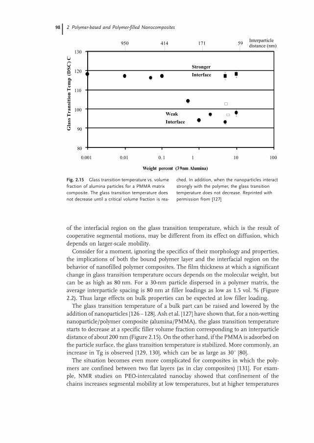
of the interfacial region on the glass transition temperature, which is the result ofcooperative segmental motions, may be different from its effect on diffusion, whichdepends on larger-scale mobility.Consider for a moment, ignoring the specifics of their morphology and properties,
the implications of both the bound polymer layer and the interfacial region on thebehavior of nanofilled polymer composites. The film thickness at which a significantchange in glass transition temperature occurs depends on the molecular weight, butcan be as high as 80 nm. For a 30-nm particle dispersed in a polymer matrix, theaverage interparticle spacing is 80 nm at filler loadings as low as 1.5 vol. % (Figure2.2). Thus large effects on bulk properties can be expected at low filler loading.The glass transition temperature of a bulk part can be raised and lowered by the
addition of nanoparticles [126–128]. Ash et al. [127] have shown that, for a non-wettingnanoparticle/polymer composite (alumina/PMMA), the glass transition temperaturestarts to decrease at a specific filler volume fraction corresponding to an interparticledistance of about 200 nm (Figure 2.15). On the other hand, if the PMMA is adsorbed onthe particle surface, the glass transition temperature is stabilized. More commonly, anincrease in Tg is observed [129, 130], which can be as large as 308 [80].The situation becomes even more complicated for composites in which the poly-
mers are confined between two flat layers (as in clay composites) [131]. For exam-ple, NMR studies on PEO-intercalated nanoclay showed that confinement of thechains increases segmental mobility at low temperatures, but at higher temperatures
80
90
100
110
120
130
0.001 0.01 0. 1 1 10 100
Weight percent (39 nm Alumina)
Gla
ss T
ra
nsi
tio
n T
em
p (
DS
C)
C
Weak
Interface
Stronger
Interface
950 414 171 59Interparticledistance (nm)
Fig. 2.15 Glass transition temperature vs. volume
fraction of alumina particles for a PMMA matrix
composite. The glass transition temperature does
not decrease until a critical volume fraction is rea-
ched. In addition, when the nanoparticles interact
strongly with the polymer, the glass transition
temperature does not decrease. Reprinted with
permission from [127]
2 Polymer-based and Polymer-filled Nanocomposites98

a less mobile fraction is revealed. This suggests a broadening in the relaxation spectra.In addition, the glass transition temperature is suppressed. In thin films this is attrib-uted to a highly immobilized polymer layer. Krishnamoorti [131], armed with theknowledge that the rate of polymer intercalation into the clay layers can be as fastas the diffusion rate in the bulk, suggested that this phenomenon is due only to non-cooperative motion. This is clearly an area in need of further study and is discussedmore below.In addition to changes in the mobility of a polymer chain, the average chain con-
formation can be altered and/or the type and degree of crystallinity can change. Dhi-nojwala and coworkers recently reported measurements on a polystyrene (PS)/sap-phire interface [132, 133], which revealed a nearly perpendicular orientation of thephenyl rings to the PS/sapphire interface. It is unclear how these conformationschange in the presence of a nanostructured surface, particularly one with a high ra-dius of curvature. Recent modeling, however, suggests that studies on flat surfacesmay be relevant [134]; however, it is unclear how the many techniques used to studybehavior on flat surfaces could be modified to measure this. Studies have focused onthe effect of structural details of surfaces on protein structure and have found that thedensity of alkane chains on an alkylated surface directly affects the amount of proteinadsorbed [135]. Other studies [136–138] showed that vitronectin (a mediator of osteo-blast adhesion) remained folded onmonolithic alumina withmicrometer-sized grains,but showed enhanced adsorption as well as conformational changes when it was ad-sorbed on nanograined alumina. Vitronectin interactions with nanoceramics werecorrelated with significantly enhanced osteoblast adhesion. The change in polymerchain conformation, in contrast to that of proteins, is likely to be much more local,but could still affect bulk properties.Crystallinity is also sensitive to surface interactions. This is seen dramatically in
graphite fiber/polypropylene composites in which a transcrystalline layer developsperpendicular to the fiber [139]. Nanofillers can also change the degree of crystalli-nity, change the rate of crystallization, and/or suppress the formation of the thermo-dynamic crystal phase and stabilize the metastable phase [140, 141]. In silica-filledNylon 11 that was thermally sprayed, the crystallinity increased due to the presenceof the nanoparticles [142]. In montmorillonite/HDPE nanocomposites, the polymercrystals decreased in size and the crystallization rate decreased [143], whereas in poly-amide (Nylon 6) composites the metastable hexagonal phase formed instead of thetypical monoclinic phase [144]. Another example in Nylon 6 occurs under high pres-sure: by annealing montmorillonite/ Nylon 6 at high pressures, a higher-temperaturemonoclinic phase forms (a), and the orthorhombic (c) phase is suppressed [145].Finally, changes in the chemistry can occur in the interfacial region. A dramatic
example of this is the preferential adsorption of a curing agent onto the nanofiller.When this occurs, the region surrounding the nanoparticle consists of a ‘layer’ ofstoichiometrically crosslinked thermoset with excess curing agent, surrounded by a‘layer’ of depleted curing agent and thus less-than-stoichiometric crosslinking. Thisphenomenon has been observed in fiber-filled polymers [146] and is presumed toexist in nanoscale titania-filled epoxy [147]. More subtle changes could also occur,such as preferential adsorption of low-Mw material to the surface.
2.3 Inorganic Filler–Polymer Interfaces 9999

In summary, the interfacial region is complex, and when the interfacial area is verylarge, the whole polymer matrix may essentially be interfacial region. This presentsone of the essential challenges in polymer nanocomposites: to develop technology tocontrol the interface, to describe the interface mathematically, and to be able to predictproperties taking into account the interfacial region. Traditional composite theory,although very far advanced in describing properties that are relatively independentof the interface, is still in its infancy in taking into account the role of the interfacialregion. Significant progress has been made in understanding the interaction of poly-mers with flat surfaces, but the interaction of polymers with highly curved surfacesand at scales similar to that of the radius of gyration is not well understood. The na-nocomposites community has their work cut out for them.
2.4
Processing of Polymer Nanocomposites
One of the key limitations in the commercialization of nanocomposites is processing.Early attempts at clay-filled polymers required processing that was not commerciallyfeasible, but this situation has changed. Similarly, processing of other nanocompositesis becoming easier and more commercially viable as our understanding improves. Aprimary difficulty is proper dispersion of the fillers. Without proper dispersion anddistribution of the fillers, the high surface area is compromised and the aggregates canact as defects, which limit properties. To facilitate discussion, we will define the state ofaggregation in those nanocomposites. Distribution of a nanofiller describes the homo-geneity throughout the sample, and the dispersion describes the level of agglomera-tion. Figure 2.16 schematically illustrates good distribution but poor dispersion (a),poor distribution and poor dispersion (b), poor distribution but good dispersion(c), and good distribution and good dispersion (d). The state of aggregation is furtherdefined in layered silicate/polymer nanocomposites later in this chapter.
2.4.1
Nanotube/Polymer Composites
The processing of nanotube/polymer composites is still in its infancy. Although na-notubes have been incorporated into composites commercially, the literature describ-ing the processes is limited. Significant issues remain to be solved about purification,dispersion, and bulk processing.The ability to disperse SWNT and MWNT into a polymer may be the most critical
processing parameter for controlling properties. Nanotubes that are in clumps or areagglomerated with other carbonaceous materials create defect sites that will initiatefailure. In addition, they limit the efficiency with which the nanotubes carry load.This limitation has been illustrated explicitly in both polymer and ceramicmatrix com-posites [148, 149]. CVD-grown MWNT, which are easily dispersed and less agglom-erated, increased the modulus and strength of polystyrene without compromising the
2 Polymer-based and Polymer-filled Nanocomposites100

strain-to-failure factor significantly. Other work on arc-discharge-grown MWNT,which were not fully purified and not as well dispersed, did not show the increasein toughness observed for well-dispersed MWNT. Similarly, the toughness ofMWNT/alumina composites with excellent dispersion increased significantly com-pared to composites with somewhat worse dispersion.Dispersion has been achieved primarily by sonication of nanotubes in a solvent. The
most focused efforts have been on the dispersion of SWNT. Chemical modification ofthe surface with the aid of surfactants [150], by functionalization of the end-caps withlong aliphatic amines [151], or by functionalization of the sidewalls with fluorine [152]or alkanes [153] has resulted in stable suspensions of nanotubes. None of these meth-ods is ideal for composite processing. The use of surfactant results in an impurity inthe composite. Functionalizing the ends limits further chemical modifications forcontrolling bonding with the matrix, and modification of the sidewalls can affectthe mechanical properties [154]. As an alternative, the best solvents for direct disper-sion of SWNT were identified as NMP, DMF, hexamethylphosphoramide, cyclopen-tane, tetramethylene sulfoxide, and e-caprolactone [154]. These solvents are all strongLewis bases without hydrogen donors, although not all solvents with these character-istics were good solvents for SWNT.After dispersion, drying the dispersion on a glass slide and placing resin directly
onto a thin film of nanotubes [29, 155, 156] can produce small-scale composites. Mix-
(a)
(b)
(c)
(d)
Fig. 2.16 A schematic illustrating the difference between dispersion and distri-
bution and giving examples of good and poor for each
2.4 Processing of Polymer Nanocomposites 101101

ing both the nanotubes and the polymer in the presence of a solvent [25, 30, 157, 158],often with the help of a surfactant [159], can also produce composites. Figure 2.17ashows the wetting and the dispersion of SWNT dispersed in ethanol and then mixedwith an epoxy resin [157]. Figure 2.17b [148] shows the dispersion achieved with CVD-grown MWNT, dispersed in toluene with dissolved polystyrene and casting films.Excellent dispersion was achieved. Nanotubes have also been dispersed directlyinto liquid urethane acrylate polymer [160], methylmethacrylate monomer [161],and epoxy resin [162], followed by curing or polymerization. Damage to the nanotubesis a tradeoff that must be considered.
Fig. 2.17a Transmission electron micrograph of aligned
singlewall carbon nanotube ropes bridging an elliptical hole
in a polymer film. Reprinted with permission from [157]
Fig. 2.17b Treansmission elec-
tron micrograph of MWNT-PS
film in which the nanotubes are
homogeneously distributed in
the polystyrene matrix at a
1 lm length scale. The inset is
the MWNT weight fraction as a
function of length scale, which
was determined by measuring
the weight fraction of nanotubes
at areas in the image. The error
bars represent the standard de-
viation of the experimental data,
which reflects the homogeneity
of the distribution. Reprinted
with permission from [148]
2 Polymer-based and Polymer-filled Nanocomposites102

Nanofibers have been successfully melt-mixed with polyphenylene ether/polyamidematrices in a twin screw extruder. This process has led to a commercial product inconductive thermoplastics for electrostatic painting without the loss of mechanicalproperties [163].An interesting composite processed from nanotubes is a macroscopic fiber that is a
mixture of nanotubes and a traditional material used for carbon fibers, such as pitch orPAN. This was achieved with a pitch-basedmatrix and led to interesting improvementsin properties, because the pitch fibers were not subjected to the typical high tempera-ture processing [164].
2.4.2
Layered Filler–Polymer Composite Processing
Scientists have known for about 40 years that polymers interact strongly with mon-tmorillonite and that the clay surface can act as an initiator for polymerization [165,166]. Patents for clay/Nylon 6 composites were not issued until the 1980s, at whichpoint the clay/polymer nanocomposites were commercialized [167]. The improvementthat led to commercialization was the appropriate dispersion of the clays at the nan-ometer scale.The first step in achieving nanoscale dispersion of clays in polymers is to open the
galleries and to match the polarity of the polymer or monomer so that it will intercalatebetween the layers. This is done by exchanging an organic cation for an inorganiccation (Figure 2.18). The larger organic cations swell the layers and increase the hy-drophobic properties of the clay [168] (Figure 2.18), resulting in an organically mod-ified clay. The organically modified clay can then be intercalated with polymer by sev-eral routes. Solution processing involves dispersion of both the organically modifiedclay and the polymer in a common solution. Variations on this process include emul-sion or suspension polymerization [169, 170]. Highly polar polymers such as Nylon[171] and polyimides [8] are more easily intercalated than nonpolar polymers such aspolypropylene, because polar polymers have a higher affinity for the polar clay gal-leries. In situ polymerization intercalates monomer directly into the organically mod-ified clay galleries, and the monomer can either adsorb onto the layer surface [172] orbe anchored by free radical techniques [173]. Melt intercalation involves mixing theclay and a polymer melt, with or without shear. The success of melt intercalation issurprising, given that the gallery spacing is only about 2 nm and the radius of gyrationof the polymer is significantly larger than this. Even more surprising is that the speedof melt intercalation is faster than that of self diffusion of polymers and scales with theinverse of the molecular weight [174]. Coarse-grained molecular dynamics studiespredict a rate twice that of self-diffusion, with the rate scaling inversely with the mo-lecular weight. The results of molecular dynamics and experimental studies agree thatthe stronger the clay/polymer interaction, the slower the intercalation rate [175]. Inaddition, layer flexibility seems to control the mechanism of intercalation [176], per-haps due to a recently proposed mechanism called the ‘kink’ model of melt intercala-tion [177], in which sufficient shear force causes a kink to form in the clay sheet (a form
2.4 Processing of Polymer Nanocomposites 103103

of compression failure) (Figure 2.19). Polymer can then penetrate the new space be-tween the layers. This kink can propagate along the layer, and more polymer can inter-calate. This mechanism can explain both the fast intercalation rate (which is enhancedby the space created by kinking) and the dependence on layer flexibility. Layers with alower modulus should kink more easily. A rigorous test of this model is still required.Models have also been developed to test the tendency for chains to melt-intercalate inthe absence of shear [178, 179]. These studies showed that there is an optimal inter-layer separation (slightly larger than the pseudobilayer for intercalation of polystyrene)and an optimal chemical interaction (the greater the hydrophilicity of the polymer, theshorter the organic modifier should be). This minimizes unfavorable interactions be-tween the polymer and the aliphatic chain. Polar polymers are also more likely tointercalate.As the layer spacing increases, the process can be monitored by x-ray diffraction
(XRD). Intense peaks between 38 and 98 indicate an intercalated composite, but ifthe peaks are extremely broad or disappear completely, this indicates complete exfo-liation. Figure 2.20 [180] shows the XRD pattern of organically modified montmor-illonite (d), an intercalated montmorillonite (c), and two exfoliated montmorillonitenanocomposites (a, b).
Inorganic cation / organic cationexchange
Na+
+
+ + +
+ + +
+ + +
Clay
Organically modified clay
+ + +
+ + +
+ + +
Monomer,
oligomer intercalation
+ + +
+ + +
+ + +
Intercalated nanocomposite
Polymer melt or solution
intercalation
Polymerization
Fig. 2.18 Schematic of the basic steps in processing clay-filled polymers
2 Polymer-based and Polymer-filled Nanocomposites104

Once the clays have been intercalated with polymer, the nanocomposites can beprocessed by traditional melt-processing methods. This final processing of the com-posite is important in determining the final properties. Mixing facilitates nanoscaledispersion and can lead to clay and/or polymer chain alignment. The degree of shearduring molding determines, not only the degree of clay layer alignment, but also thedegree of crystallite alignment. For example, extruded Nylon sheet with a draw ratio of4:1 had a higher modulus than a sheet processed by injection molding [181]. This maybe due to a higher degree of platelet and crystallite alignment and is a commonphenomenon in the drawing of Nylon. In some cases, the crystallinity increases
Fig. 2.19 Schematic of the kink model of melt intercalation. Ag denotes the
agglomerated (immiscible) portion of the clay, and Int. denotes the intercalate
state. Redrawn from Fig. 1(a) of [177]
Fig. 2.20 X-ray diffraction data showing the dif-
fraction patterns that result from (a), (b) exfoliated
clays, (c) intercalated clays, (d) organically modified
clays. Reprinted with permission from [180]
2.4 Processing of Polymer Nanocomposites 105105

(36%–38%, compared to 31% for unfilled Nylon) and remains constant with fillercontent [140]. Other studies, however, have shown decreases in crystallinity [182]. In-creasing the pressure during processing to 0.1–0.6 GPa favors the a phase [145]. Theclay platelets also enhance alignment of the Nylon 6 chains and the crystallites [140],though the extent is governed by the degree of shear and can vary across the thicknessof an injection-molded part [183]. Understanding and optimizing the mixing and tak-ing advantage of interesting rheology and other phenomenon such as strain hardeningand rheopexy is in its infancy, and significant fundamental work still needs to be done[184].The resulting nanocomposites can have several structures (Figure 2.21). The struc-
ture of an intercalated nanocomposite is a tactoid with expanded interlayer spacing,but the clay galleries have a fixed interlayer spacing. Exfoliated nanocomposites areformed when the individual clay layers break off the tactoid and are either randomlydispersed in the polymer (a disordered nanocomposite) or left in an ordered array.The following sections give some details on processing clay/polymer nanocompo-
sites. The discussion is organized by matrix type.
A. Conventional Composite with Tactoids
B. Intercalated Nanocomposite
C. Ordered ExfoliatedNanocomposite
D. Disordered ExfoliatedNanocomposite
Fig. 2.21 Schematic of the microstructures that can develop in clay-filled polymer composites:
(a) a conventional composite with tactoids, (b) an intercalated nanocomposite, (c) an ordered
exfoliated nanocomposites, (d) a disordered exfoliated nanocomposite
2 Polymer-based and Polymer-filled Nanocomposites106

2.4.2.1 Polyamide Matrices
Nylon-6/Nylon-12/clay hybrid composites were the first exfoliated smectic clay com-posites made [187]. Montmorillonite, with a CEC of 119mEq/100 g, was intercalatedwith 12-aminolauric acid, which increased the intergallery spacing from 1.0 to 1.7 nm.This ‘12-montmorillonite’ was then mixed with e-caprolactam, which increased theintergallery spacing even further, to 4.0 nm, indicating that the e-caprolactam hadintercalated into the galleries. Heating to 250 8C led to polymerization, forming aclay/Nylon-6 nanocomposite. Further research [185] determined that e-caprolactamcould intercalate directly into the galleries of montmorillonite in a hydrochloricacid solution and, upon intercalation, becomes oriented vertically in the galleries.The modified montmorillonite then mixed easily with additional molten e-caprolac-tam and 6-aminocaproic acid, yielding a Nylon-6 homopolymer/clay nanocompo-site. The montmorillonite was completely exfoliated. Recently [186], montmorillo-nite/Nylon 6 nanocomposites were processed by melt intercalation. Although the de-gree of exfoliation was not as high as in nanocomposites produced by the above meth-ods, at weight fractions less than 0.1 the composites were primarily exfoliated.
2.4.2.2 Polyimide Matrices
The preparation of polyimide matrix clay nanocomposites involves several steps [8,187] (Figure 2.22). By intercalating montmorillonite with the ammonium salt of do-decylamine, it becomes soluble in dimethylacetamide (DMAC). DMAC is also a sol-vent for 4,4’-diaminodiphenylether and pyrometllitic dianhydride, the precursors forpolyamic acid and, as such, polyimides. After intercalation of the ammonium salt of
Fig. 2.22 Schematic of the synthesis of polyimide-clay hybrid film. Reprinted
with permission from [187]
2.4 Processing of Polymer Nanocomposites 107107

dodecylamine, x-ray studies [188] showed that hectrite (CEC = 55mEq/100 g) has onemonolayer of organic material between the layers, whereas saponite, montmorillonite,and synthetic mica (all with CEC > 100mEq/100 g) have two. After composite forma-tion, however, only the montmorillonite and the synthetic mica have exfoliated com-pletely, but the hectrite and saponite remain in a somewhat aggregated state. Lan et al.[189] found aggregates of montmorillonite after using a similar procedure. More re-cently, P-phylenediamine in an HCl solution was also found to form organic-modifiedmontmorillonite that dissolves in DMAC [190]. This same study showed that the pre-sence of a small amount of nanoscale organoclay can decrease the imidization tem-perature by 50 8C (from 300 8C to 250 8C), and at 250 8C the imidization time decreasedby 15 min. The activation energy decreased by 20%. Clearly, the organoclay surface isacting as a catalyst.
2.4.2.3 Polypropylene and Polyethylene Matrices
Nonpolar polymers are very difficult to intercalate into smectic clays, because the claysare strongly polar. This challenge has been met [191, 192] by first intercalating stear-ylamine into montmorillonite and synthetic mica. Melt-mixing the organoclays withmaleic anhydride-modified polypropylene oligomers results in PP-MA intercalation.The modified organoclay is then melt-mixed with a polypropylene matrix. There is abalance between creating a polar oligomer with enoughmaleic anhydride to intercalatewell, but nonpolar enough to mix with the polypropylene. Unfortunately, the oligomerlimits the extent of property improvement achieved to date. Polyethylene has also beensuccessfully melt-mixed with modified montmorillonite and saponite after ion ex-change with dioctadecyldimethylammonium bromide. The degree of dispersion isnot excellent, and the layers are certainly not exfoliated; yet, significant modificationof both the crystal structure and properties has been observed [143].
2.4.2.4 Liquid-Crystal Matrices
Smectic clay/liquid crystalline nanocomposites exhibit interesting optical properties[193, 194]. Upon initial formation, the composites are opaque, but when an electricfield is applied they became transparent. To process these composites, montmorillo-nite was intercalated with lauryl ammonium or 4-(4’-cyanobiphenyl-4-oxy) butyl am-monium (CBAM), or 4-cyano-(4’-biphenyloxy) undecyl ammonium cation and solu-tion-mixed with a nematic crystal matrix such as 4-pentyl-4’-cyanobiphenyl (5CB)and nematic TFALC (a mixture of low-molar-mass liquid crystals).
2.4.2.5 Polymethylmethacrylate/Polystyrene Matrices
The processing of clay/PMMA or clay/PS composites was first done by directly inter-calating themonomer into the clay, followed by polymerization [195]. Thismethod wasnot successful in exfoliating the clays. At issue again is the compatibility between theclay and the monomer. One solution for PMMA has been to use appropriate ammo-nium salts [196, 197], which may be reactive [198]. Another solution is to use a como-nomer as a compatibilizer [199]. A similar solution was found for polystyrene by using
2 Polymer-based and Polymer-filled Nanocomposites108

the reactive cationic surfactant vinylbenzyldimethyldodecylammonium as the interca-lant [200]. Exfoliated graphite/polystyrene composites have been made by similar pro-cessing methods [80]. Recently, a commercially viable process was developed [180] forpolystyrene in which montmorillonite intercalated with octadecyl trimethyl ammo-nium chloride was melt-mixed with a styrene methylvinyloxazoline copolymer.This process resulted in complete exfoliation, which could not be achieved withpure polystyrene [201]. The hypothesis is that the hybridization is due to strong hydro-gen bonding between the oxazoline groups and oxygen groups in the silicate clays.
2.4.2.6 Epoxy and Polyurethane Matrices
Epoxy is a widely used thermoset, with applications ranging from household glues tohigh-performance composites. To improve performance, increasing the Tg of epoxyand improving its properties above the Tg are desirable. Adding clays and layeredsilicic acids to epoxy [6, 71, 202–204] can greatly improve its mechanical perfor-mance, particularly at temperatures above Tg. The processing has been studied indetail [71, 205]. In the smectic clay/epoxy composites, the length of the intercalatedorganic amine determines the ease of exfoliation, and only clays with primary andsecondary onium ions form exfoliated nanocomposites [71, 206]. After intercalationof the organic amines, the epoxy resin or a combination of resin and curing agent canbe intercalated into the smectic clays or layered silicic acids. If enough resin and curingagent are intercalated and the curing process is controlled, exfoliated nanocompositesresult. Figure 2.23 shows a diagram of the process [207]. The acidic onium ions cat-alyze the intragallery polymerization or curing of the resin. If this reaction occursmorerapidly than extragallery curing, then the clay exfoliates. Otherwise, an intercalatednanocomposite results. Therefore, careful control of temperature and time is required[71], or the ratio of resin to curing agent must be significantly less than the stoichio-metric ratio [205] in order to achieve exfoliation. An approach similar to that used forepoxy composites was used to make intercalated montmorillonite/polyurethane com-posites [208].
Fig. 2.23 Proposed pathway for formation of an
epoxy-exfoliated magadiite nanocomposite: (A) In-
itial organomagadiite with a paraffin-like gallery
structure of onium ions and neutral amine. (B)
Reorientation of the alkylammonium ions into a
lipid-like bilayer structure to accommodate the
cointercalation of epoxide and curing agent. (C)
Rapid intragallery formation of a polymer gel and
expansion of the gallery height beyond a lipid-like
layer. (D) Silicate nanolayers are completely exfo-
liated in a fully crosslinked epoxy polymer network.
Reprinted with permission from [207]
2.4 Processing of Polymer Nanocomposites 109109

2.4.2.7 Polyelectrolyte Matrices
Polyelectrolytes can be used in electrochemical devices such as solid-state batteries,electrochromic devices, and sensors [209]. The addition of layered silicates to polyelec-trolytes increases the conductivity, improves the mechanical stability, and improvesthe interfacial stability with electrode materials. Polyelectrolytes are characterizedby a large number of ionizable groups and thus are highly polar. This makes themexcellent candidates for intercalation into smectic clays. Polyvinylpyridines are of par-ticular interest because of the variety of processing methods available [210]. Interca-lated nanocomposites can be formed easily from the water-soluble hydrobromide saltof the 1,2 or 1,6 polyelectrolyte (1,2 or 2,6 polyvinylpyridinium cations). However, onlya single layer of polymer intercalates, and exfoliation does not occur. A slower, butultimately more effective process, uses neutral poly-4-vinylpyridine and results inan exfoliated composite. A second method involves intercalation of 4-vinylpyridiniumsalts, followed by polymerization.Poly(ethylene oxide) (PEO) matrix composites have also been processed both by
intercalating PEO in solution into organically modified smectic clays [209] and bymelt- mixing clay with PEO and PEO/PMMA mixtures [211,212]. In neither casedoes an exfoliated composite result. Aranda and Ruiz-Hitzky [209] dissolved PEOin acrylonitrile and found that the structure of the PEO changed when the interlayercation was changed. Use of Na+ montmorillonite or NH4
+ montmorillonite resulted ineither a helical PEO or a bilayer zigzag PEO structure in the galleries. The PEO ar-rangement was reversible with exchange of the interlayer cations.
2.4.2.8 Rubber Matrices
Several applications of rubbers might benefit from inclusion of exfoliated clays. Theirgreatly reduced permeability [213] would be useful for the inner liners of tires andinner tubes [214]. In addition, modification of the glass transition temperatureand/or the loss modulus might be useful in a variety of damping applications. Mon-tmorillonite has been ion-exchanged with a protonated form of butadiene and acry-lonitrile copolymer. This was subsequently mixed with nitrile butadiene rubber inthe presence of crosslinking agents and resulted in highly dispersed nanocompo-sites. Nanocomposites have also been prepared from dioctadecyldimethyl ammo-nium-exchanged montmorillonite in poly(styrene-b-butadiene) matrices [215].Silicone rubbers have also been successfully intercalated into smectic clays. Burn-
side and Giannelis [216] intercalated Na+ montmorillonite with dimethylditallow am-monium bromide and then sonicated in a silanol-terminated poly(dimethylsiloxane)(Mw = 18,000) with a tetraethyl orthosilicate and tin 2-ethylhexanoate crosslinkingagent. Hexadecyltrimethylammonium bromide has also been used successfully asthe intercalating agent [217]. Recently, a latex method was developed in which unmo-dified clays were mixed with a rubber latex, leading to improved properties over solu-tion intercalation [218].
2 Polymer-based and Polymer-filled Nanocomposites110

2.4.2.9 Others
Clay/polymer nanocomposites that include poly(e-caprolactone) have been made viain-situ polymerization [7]. Composites that include poly(p-pheylenevinylene) havebeen made via intercalation of poly(xylylenedimethylsulfonium bromide) and subse-quent elimination of the dimethylsulfide and HBR [219]. Those including cyclic poly-carbonate [220] or polyethyleneterephthalate have been made via monomer intercala-tion and subsequent polymerization [221]; and those including polyaniline via in-situpolymerization of aniline monomer [222].
2.4.3
Nanoparticle/Polymer Composite Processing
There are three general ways of dispersing nanofillers in polymers. The first is directmixing of the polymer and the nanoparticles either as discrete phases or in solution.The second is in-situ polymerization in the presence of the nanoparticles, and the thirdis both in-situ formation of the nanoparticles and in-situ polymerization. The latter canresult in composites called hybrid nanocomposites because of the intimate mixing ofthe two phases.
2.4.3.1 Direct Mixing
Direct mixing takes advantage of well established polymer processing techniques. Forexample, polypropylene and nanoscale silica have beenmixed successfully in a two-rollmill [5], but samples with more than 20 wt. % filler could not be drawn. This is typicaland is a limitation of this kind of processing method. Nanoscale silica/PP compositeshave been processed in a twin-screw extruder, but the dispersion was successful onlyafter modification of the silica interface to make it compatible with the matrix [223]. ABrabender high-shearmixer has been successfully used tomix nanoscale alumina withPET, LDPE [224]. Thermal spraying has also been successful in processing nanopar-ticle-filled Nylon [142]. When these traditional melt-mixing or elastomeric mixingmethods are feasible, they are the fastest method for introducing new products tomarket, because the composites can be produced by traditional methods. This hasbeen successful in many cases, but for some polymers, the viscosity increases rapidlywith the addition of significant volume fractions of nanofiller, which in turn can limitthe viability of this processing method.In addition to viscosity effects, nanoparticles can either enhance or inhibit polymer
degradation. One method for measuring degradation is to place the polymer in a high-shear mixer and measure the torque as a function of time and temperature. As thematerial crosslinks, the torque begins to increase (at a constant speed), and when chainscission begins, the torque decreases. This leads to a peak in the torque, whose posi-tion is often used as a measure of the degradation time. A recent study on ZnO/LDPEcomposites showed that, for nanoparticle/matrix mixtures, the time at the peak in-creased by a factor of almost 2 [224]; however, micrometer-size particles decreasedthe degradation time. In other instances, the catalytic nature of the nanoparticlesgreatly decreases the degradation time [225]. Whether degradation is inhibited or en-
2.4 Processing of Polymer Nanocomposites 111111

hanced depends on the particle surface activity and the increased interfacial area (par-ticle size).
2.4.3.2 Solution Mixing
Some of the limitations of melt-mixing can be overcome if both the polymer and thenanoparticles are dissolved or dispersed in solution. This allows modification of theparticle surface without drying, which reduces particle agglomeration [226]. The na-noparticle/polymer solution can then be cast into a solid, or the nanoparticle/polymercan be isolated from solution by solvent evaporation or precipitation. Further proces-sing can be done by conventional techniques.
2.4.3.3 In-Situ Polymerization
Another method is in-situ polymerization. Here, nanoscale particles are dispersed inthe monomer or monomer solution, and the resulting mixture is polymerized by stan-dard polymerization methods. One fortunate aspect of this method is the potential tograft the polymer onto the particle surface. Many different types of nanocompositeshave been processed by in-situ polymerization. A few examples are silica/Nylon6 [227,228], silica/poly 2-hydroxyethylmethacrylate [229], alumina/polymethylmethacrylate[230], titania/PMMA [231], and CaCO3/PMMA [232]. The key to in-situ polymeriza-tion is appropriate dispersion of the filler in the monomer. This often requires mod-ification of the particle surface because, although dispersion is easier in a liquid thanin a viscous melt, the settling process is also more rapid.
2.4.3.4 In-Situ Particle Processing – Ceramic/Polymer Composites
An interesting method for producing nanoparticle-filled polymers is in-situ sol–gelprocessing of the particles inside the polymer. The process has been used successfullyto produce polymer nanocomposites with silica [233] and titania [234] in a range ofmatrices [235]. The overall reaction for silica from tetrethylorthosilicate (TEOS) isshown below.
Si(OC2H5)4 + excess H2O ! SiO2 + 4C2H5OH
The composites can be formed in one of several ways. In the first method, a copolymerof the matrix polymer and silica precursor are mixed, and the sol–gel reaction is al-lowed to progress. Figure 2.24 shows an example of the process for silica/polystyrenecomposites [233]. During drying, the polymer blocks phase-separate and the silicaregions coalesce. A second approach mixes a silica precursor such as TEOS [236]with a polymer such as polyvinylacetate [237], polyetherimide [238], or polymethylme-thacrylate [239]. For example, a recent paper on the processing of TiO2/poly(styrenemaleic anhydride) resulted in excellent dispersion of TiO2 in PSMA [234]. Direct addi-tion of TiO2 to a PSMA solution resulted in serious aggregation. Therefore, PSMAwasdissolved in THF, and then tetrabutyl titanate was added under the appropriate condi-tions. Because the uncondensed TiOH and maleic anhydride could react, the polymer
2 Polymer-based and Polymer-filled Nanocomposites112

coated the titania particles as they formed and prevented agglomeration. A combina-tion of these first two methods has been used for silica/polydimethylsiloxane (PDMS)composites in a two step process. First, an unfilled PDMS network was formed, withTEOS as the end-linking agent. The network was then swelled with TEOS and the sol–gel reaction was catalyzed [240]. Significant work on determining the parameters affec-ting particle size has been accomplished with this method [241].Finally, the polymer and ceramic can be polymerized simultaneously, and compo-
site materials ranging from a few percent to 100% inorganic phase can be formed[242]. For example, silica/polyacrylate nanocomposites were formed with the simul-taneous polymerization of HEMA (2-hydroxyethyl methacrylate) and tetraethoxysilane(TEOS) [229]. This resulted in a continuous interpenetrating network of silica andpolyacrylate. There is a rich chemistry here that has been reviewed elsewhere onthe processing of materials that range from glasses to polymers [243, 244] in whichthere is little if any phase separation between the organic and inorganic. We focus hereon systems with discrete, isolated phases.An interesting variation on in-situ formation of nanoparticles and polymerization is
CVD deposition of nanocomposite films [245]. Here, the chemical precursors aremod-ified separately and are mixed only just before deposition. Dichloro-p-xylylene wasused as a precursor for poly(dichloro-p-xylyene), and diacetoxydi-tert-butoxysilanewas used a precursor for silica. The resulting microstructure has discrete polymerand silica phases. This method is promising for the creation of interlayers with alow dielectric constant.Barium titanate/polymer nanocomposites have also been prepared in situ by mixing
a titanium alkoxide with a polymer and then casting and drying films. The films arethen reacted with an aqueous solution containing barium, resulting in nanoscale bar-ium titanate particles within a polymermatrix [246, 247]. Making the precursor and thepolymer compatible improves the degree of dispersion, and using compounds thattend to form micelles can introduce controlled heterogeneity [246].Nanosized calcium phosphate particles have been processed by an in-situ deposition
technique in the presence of polyethylene oxide (PEO) or PEO/PVAc mixtures [248].
Fig. 2.24 Example of in-situ synthesis of silica particles in polystyrene. Reprinted with permission from
[233]
2.4 Processing of Polymer Nanocomposites 113113

In this method, a polymer-calcium chloride complex is blended with trisodium phos-phate. As the phosphate and chloride ions diffuse through the polymer, a gel-likeprecipitate forms. This can be separated; the size and morphology can be varied bychanging the polymer and/or the polymer concentration.
2.4.3.5 In-Situ Particle Processing – Metal/Polymer Nanocomposites
Metal/polymer nanocomposites have also been processed via in-situ formation of me-tal particles from suitable metal precursors. The reaction occurs in the presence of aprotective polymer, which limits the size of the particles. Figure 2.25 [249] shows areduction scheme that uses a gold precursor and polypyrrole. Once a stable suspen-sion of metal particles is prepared in the presence of a polymer, the composite can becast, or additional monomers, of the same or a different polymer type, can be added toform a nanocomposite.Mayer [250] wrote an excellent review paper on the processing of metal/polymer
nanocomposites via in-situ methods in 1998. She reviewed the parameters that affectparticle size, stability, and morphology. Several primary parameters controlled theparticle size, including the choice of metal precursor and the metal/polymer interac-tion. For example, if PdCl2 is compared with (NH4)2PdCl4, the former tends to formhalogen-bridged complexes and thus tends to form agglomerates of nanoparticles, butthe latter does not. The interaction of the metal precursor with the polymer is alsoimportant. If the polymer has a stronger interaction with the precursor, then the par-ticle size tends to be reduced [251], because the metal precursors are prevented fromphase separating. In general, becausemost polymers are hydrophobic, precursors witha more hydrophobic character result in stronger interactions and thus smaller particlesize. Complicating this situation is the ability of the polymer to form a stable suspen-sion in solution. The rate of reduction affects the particle size, with faster reductionmethods resulting in smaller particles [252, 253].Another method giving more specific control over particle size and morphology is
the use of either micelles formed from amphiphilic block copolymers (ABC) [254] orcrosslinked/gelledmatrices. For example, through the use of crosslinking and gelation
Fig. 2.25 Schematic of reaction leading to in-situ gold particles in a polymer. Reprinted with permission
from [249]
2 Polymer-based and Polymer-filled Nanocomposites114
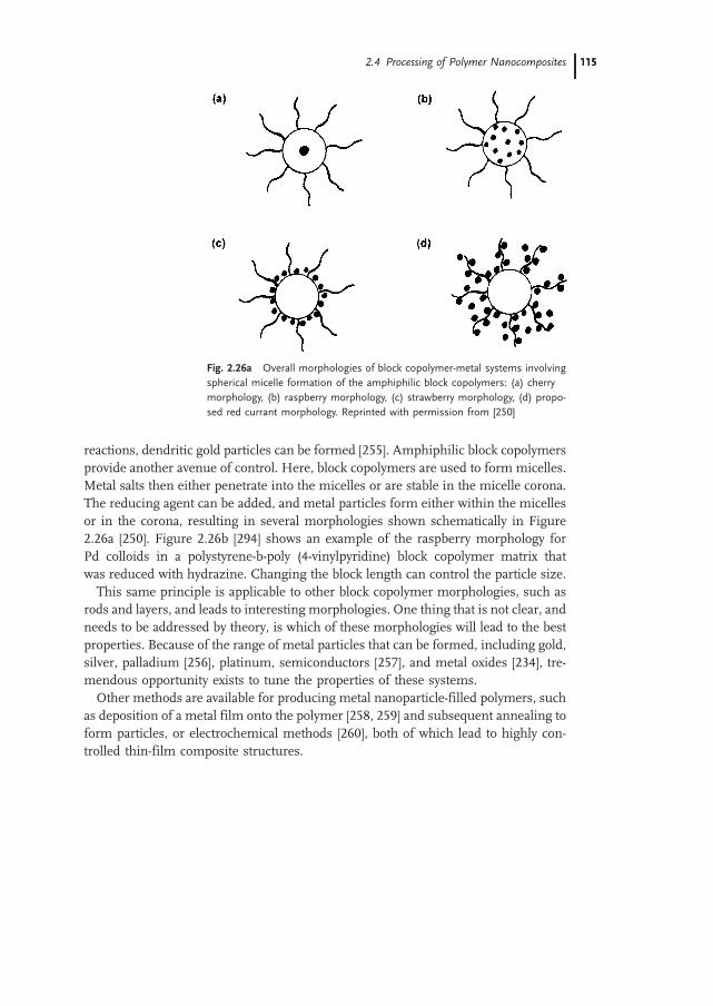
reactions, dendritic gold particles can be formed [255]. Amphiphilic block copolymersprovide another avenue of control. Here, block copolymers are used to form micelles.Metal salts then either penetrate into the micelles or are stable in the micelle corona.The reducing agent can be added, and metal particles form either within the micellesor in the corona, resulting in several morphologies shown schematically in Figure2.26a [250]. Figure 2.26b [294] shows an example of the raspberry morphology forPd colloids in a polystyrene-b-poly (4-vinylpyridine) block copolymer matrix thatwas reduced with hydrazine. Changing the block length can control the particle size.This same principle is applicable to other block copolymer morphologies, such as
rods and layers, and leads to interesting morphologies. One thing that is not clear, andneeds to be addressed by theory, is which of these morphologies will lead to the bestproperties. Because of the range of metal particles that can be formed, including gold,silver, palladium [256], platinum, semiconductors [257], and metal oxides [234], tre-mendous opportunity exists to tune the properties of these systems.Other methods are available for producing metal nanoparticle-filled polymers, such
as deposition of a metal film onto the polymer [258, 259] and subsequent annealing toform particles, or electrochemical methods [260], both of which lead to highly con-trolled thin-film composite structures.
Fig. 2.26a Overall morphologies of block copolymer-metal systems involving
spherical micelle formation of the amphiphilic block copolymers: (a) cherry
morphology, (b) raspberry morphology, (c) strawberry morphology, (d) propo-
sed red currant morphology. Reprinted with permission from [250]
2.4 Processing of Polymer Nanocomposites 115115

Fig. 2.26b Electron micrographs of Pd colloids synthesized in Ps-bP4VP block copolymers via reduction
with hydrazine. Reprinted with permission from [253]
2 Polymer-based and Polymer-filled Nanocomposites116

2.4.4
Modification of Interfaces
Literature on the modification of interfaces of traditional composite fillers is extensive.Many of the methods, however, are not directly applicable to nanocomposites for sev-eral reasons. Carbon and glass fibers are usually coated as long fibers on a spool, whichis not practical for nanofibers. In addition, methods that require drying the particlesare not appropriate for metal oxide and metal nanoparticles, because during drying(even at only 100 8C), they may agglomerate significantly. Freeze-drying methodsare more appropriate. Although describing the relevant chemical processes is impor-tant for understanding nanofiller interfacemodification, this section focuses primarilyon the results of modification, instead of on the detailed chemistry.
2.4.4.1 Modification of Nanotubes
Several reasons exist for modifying nanotubes. The first is to render them more dis-persible in solution, thus providing a route toward further functionalization or use inapplications. The second is to improve the interaction of the nanotubes with polymermatrices. Modifying the surface activity of MWNT has focused primarily on dopingthem with other elements. Doping MWNT with boron has resulted in changes in theelectronic states [261, 262] and formation of a p-type semiconductor. In addition, bor-on substitution, as well as other electron-rich substitutions, may very well lead to out-of-plane bonding configurations that increase the reactivity of the surface with a poly-mermatrix. Nitrogen doping of MWNT creates an n-type semiconductor and leads to abamboo-like structure having ordered regions connected via disordered regions [263].The nitrogen creates nitrogen-rich cavities in the otherwise graphitic nanotube. Pre-liminary work has shown that nitrogen doping changes the interface enough to im-prove the dispersion of nanotubes and results in enough bonding with epoxy matricesto increase the glass transition temperature by 208 as well as in increased modulus andstrength [264]. In addition, acid treatments and subsequent chemical reactions canlead to attachment of epoxy groups or even particles to MWNT [265, 266].SWNT are assembled as ropes or bundles. To maximize their interaction in a poly-
mer matrix, they need to be chemically modified and separated from the bundles. Oneway to increase the chemical activity is to use an SWNT with a smaller radius of cur-vature [267]. A second method is to add functional groups to the ends of SWNT. Car-boxylic groups have been linked to SWNT ends, and then the SWNT have been teth-ered to nanoparticles via thiol linkages [268–270]. SWNT have been placed in solventthrough the addition of octadecylamine groups on the ends and a small amount ofdichlorocarbenes on the sidewalls [271]. The first successful method for adding func-tional groups to the sidewalls involved fluorination at elevated temperatures. The tubescould then be solvated in alcohols and reacted with other species, particularly strongnucleophiles such as alkylithium reagents [272]. A simpler route based on a processused on other carbon species [273, 274] was developed, in which an aryl diazonium saltwas reduced electrochemically, resulting in a free radical that can attach to the carbonsurface of small diameter tubes [271] (Figure 2.27).
2.4 Processing of Polymer Nanocomposites 117117

The most exciting development in terms of composites, however, is the dissolutionof full-length SWNT that have been separated from the bundles [275]. Given the issuesof slipping of nanotubes within a bundle discussed earlier, their use in compositesrequires separation from the bundles. The process involves, first, partially breakingup the SWNT bundles in an acidic solution. Carboxylic acid groups are then addedto the ends of the tubes. Finally, the SWNT are placed in an octadecylammonium(ODA) melt for several days. This results in exfoliated nanotubes. This important re-sult should eventually lead to SWNT/polymer composites with the SWNT separated inthe polymer, which will provide an avenue for taking advantage of the extraordinaryproperties of SWNT.The development of methods to attach polymers to nanotubes has progressed sig-
nificantly. First, separation of the nanotubes from their aggregates is required. Thisseparation can be achieved by dispersion in the appropriate solvents with or withoutthe aid of a surfactant [276] and/or by choosing an appropriate synthesis method. Apolymer chain can then be attached to a bonding site by sonication [277], plasma ac-tivation [278], chemical etching of the tube ends [279], or chemical adsorption [280].These advances should lead in the near future to some very interesting copolymerswith SWNT as one block in the polymer and a rich interfacial chemistry. Some evi-dence suggests that polymers can be patterned by the nanotube surface, providing amethod for templating polymer structures near the surface [281]. It is not clear yetwhat role this interface control will have in terms of properties of composites, butto develop technology that fully exploits the properties of nanotubes in composites,control over the interface is required.
2.4.4.2 Modification of Equi-axed Nanoparticles
A recent review by Frank Caruso [282] provides extensive background on the modi-fication of nanoparticle surfaces. He cites two primary methods for modifying an in-organic nanoparticle surface with organic molecules. The first requires connecting ashort-chain molecule such as a siloxane onto the surface through grafting or stronghydrogen bonding. The second involves application of a coating by polymerizing apolymer onto the nanoparticle. In addition, inorganic coatings can be applied.
2.4.4.3 Small-Molecule Attachment
Both metal and metal-oxide nanoparticles are readily modified with small molecules.They tend to have hydroxyl groups on the surface, although the number of hydroxylgroups and the strength of the metal-OH bond varies. The most common method
Fig. 2.27 Electrochemical re-
duction of an aryl diazonium salt
to yield, giving a reactive radical
that covalently attaches to a
carbon surface. Reprinted with
permission from [271]
2 Polymer-based and Polymer-filled Nanocomposites118

takes advantage of a long history of modifying metal-oxide glass fiber or filler surfaces.The hydroxyl group on the nanoparticle surface reacts with a silane coupling agent.The relative ease of the reaction depends on the nature of the nanoparticle surface(basicity vs. acidity). The silane coupling agent can have a large variety of functional-ities attached to the silanol to modify the surface. The chains can be long or short,hydrophilic or hydrophobic, and linear or bulky. This provides tremendous flexibilityin choosing a coupling agent. Changing the coupling agent can lead to control over thestrength of the interaction between the filler and the matrix, from covalent bonding torepulsion. The change in bonding leads to increases or decreases in both glass transi-tion temperature and the modulus, but large effects occur only for particles much lessthan 100 nm [128].Of course, reacting with molecules other than silanes is also common. Nanoscale
titania has been coupled with chelating agents such as lauryl sulfate [283] and withcarotenoids (natural pigments) containing a terminal carboxylate group that reactswith OH groups on the surface [284].One creative study underway provides a method for placing one, two, or several
active functional groups on the surface of nanoparticles, followed by passivation ofthe rest of the particle. This will result in controlled aggregation of the particlesinto dimers, chains, or branched chains [285] (Figure 2.28).
2.4.4.4 Polymer Coatings
Historically, polymer coatings have provided control over the compatibility of the poly-mer with thematrix and the strength of the interaction. The coating can be grafted ontothe surface of the particle or just highly adsorbed. After the particles are coated theycan be dispersed easily in a matrix of similar chemistry to make low-volume-fractioncomposites. The exciting news is that controlling interfacial interactions has movedwell beyond single-component coatings. The possibility for assembling coated nano-particles directly into useful structures, the core-shell approach, has driven significantdevelopment in multicomponent organic and inorganic coatings. The possibilities ofthis approach seem almost endless. We currently know how to graft or strongly adsorb
A
BC
Organic or
Inorganic Coating
Block Copolymer
Coating
A*
*A
Coating with
Active SitesControlled Aggregation and Functionalization
Fig. 2.28 Schematic summarizing many of the possibilities for modifying equi-axed nanoparticles
2.4 Processing of Polymer Nanocomposites 119119

several types of polymers onto a surface. In addition, we know how to polymerizepolymers with very monodisperse molecular weight and we know how to make block(di and tri) copolymers [286]. Progress has also been made in placing inorganic coat-ings onto particles. This provides flexibility in our ability to engineer the surface of theparticles being placed in composites. No longer will the coating be only for controllingthe extent of the interaction, for it may contain several layers. The role of the first layermay be to bond with the surface. The second layer may provide electrical, mechanical,or optical functionality, and the third layer may make the particle compatible with thematrix and help in controlling the properties. The final layer may have some reactivesites that could be used to bond particles together and lead to controlled aggregation ofthe nanoparticles (Figure 2.28).In principle, polymer coatings can be produced on organic and inorganic particles by
a variety of polymerization methods. Monomer adsorption and subsequent polymer-ization, heterocoagulation–polymerization [287], and emulsion polymerization [288]have been demonstrated on micrometer-scale filler surfaces [287], although not allhave been applied to nanoparticles. Monomer adsorption has been used successfullyin several studies, and initiation has occurred both chemically [289] and via irradiation[290]. One recently reported method can be used to place nanoparticles (in this casefumed silica) into a monomer such as styrene or methylmethacrylate. The mixture is
Fig. 2.29a Synthetic scheme for structurally well defined polymer-na-
noparticle hybrids. Reprinted with permission from [292]
Fig. 2.29b Proposed approach
to formation of 3-D polymer
nanocomposite material. Stage
A: synthesis of the core-shell
latex particles with hard func-
tionalized cores and soft inert
shells. Stage B: assembly of latex
particles in a 3-D close-packed
structure. Stage C: heat treat-
ment of the 3-D compact struc-
ture, which leads to flow of soft
shells and formation of a nano-
composite polymers. Reprinted
with permission from [294]
2 Polymer-based and Polymer-filled Nanocomposites120

then irradiated [290]. Themonomer penetrates the silica aggregates, and after grafting,the surfaces are more hydrophobic and blend more easily with polymers such as poly-propylene. This treatment leads to more uniform distribution of the particles andgreatly enhanced composite ductility. In some cases, the polymer is not directlygrafted onto but interacts strongly with the surface via hydrogen bonding. For exam-ple, carboxylic acids are strongly adsorbed to alumina. If the acid contains a polymer-izable group, then after adsorption, a polymer can be grown from the molecule at-tached to the surface. This has been shown for maleic acid adsorbed onto a surfaceand was used to attach AIBN-initiated 1-octadecene polymers to the surface [291].Another method that leads eventually to a composite with an ordered array of na-
noparticles involves grafting an initiator onto the surface of the nanoparticles and thenpolymerizing a grafted polymer onto the surface [292]. If living radical polymerizationis used, then the particles can be processed into a composite without additional matrix,to make high-volume-fraction composites with particles in an ordered array. Figure2.29a shows this for silica particles with grafted polystyrene packed into an orderedmatrix [292]. This process lends itself nicely to block copolymer coatings and eventriblock copolymers. Another method that can lead to multilayer structures is theuse of self-assembled polymer layers in a ‘layer-by-layer colloid templating strategy’[293]. Here, charged polymers are adsorbed onto charged particles, resulting in acoated particle with surface charge. A second charged polymer can then be exposedto the previously charged particles. When this polymer is adsorbed, the surface chargeof the particle is reversed, and the particles have a bilayer coating. This method can berepeated and enables careful control of the coating thickness and functionality.A similar core–shell approach has been used to coat a low-Tg polymer onto a high-
Tg latex particle. The coated polymer particles were then taken out of solution andannealed to create an ordered array of polymer in polymer [294] (Figure 2.29b).The concept applies to coated nanoparticles other than latex as well.
2.4.4.5 Inorganic Coatings
Inorganic coatings have also been applied to submicrometer particles via either pre-cipitation of the inorganic coating onto the particles or deposition via a sol–gel typeprocess. With these methods, silica [295], yttria [296], titania [297], titanium nitride[298], and zirconia [299] have all been applied to support particles, usually other metaloxides. The advantage of such coatings is that the nanoparticles (both organic andinorganic) can be coated with inorganics for further functionalization. For exam-ple, conducting coatings can be applied, and the optical properties can be tuned.Sonochemistry can also be used to apply inorganic coatings in much the same way
as described above for the processing of nanoparticles. For example, ZnS coatings (1–5 nm) on colloidal silica have been prepared in this way [300].
2.4 Processing of Polymer Nanocomposites 121121

2.5
Properties of Composites
2.5.1
Mechanical Properties
One of the primary reasons for adding fillers to polymers is to improve their mechan-ical performance. For example, the addition of high-modulus fillers increases themod-ulus and the strength of a polymer. In traditional composites, unfortunately, this oftencomes at the cost of a substantial reduction in ductility, and sometimes in impactstrength, because of stress concentrations caused by the fillers. Well-dispersed nano-fillers, on the other hand, can improve themodulus and strength andmaintain or evenimprove ductility because their small size does not create large stress concentrations.In addition, the large interfacial area of nanocomposites provides an opportunity foraltering the matrix properties in unique ways. This section highlights the potentialeffect of nanofillers on the modulus, failure stress/strain, toughness, glass transi-tion, and wear behavior of polymers.
2.5.1.1 Modulus and the Load-Carrying Capability of Nanofillers
In traditional composites, the modulus can be predicted, within bounds, and the me-chanism that leads to a change in modulus is load transfer. For example, if a high-modulus filler is added to a lower-modulus polymer, then load transfers from thematrix to the filler, leading to an increase in modulus. One important question fornanocomposites is how load is transferred from the matrix to the filler. This is a com-plicated question, because in some nanocomposites the polymer chain and filler arealmost the same size, and in others, the fillers are atomically smooth, with few func-tional groups to which the polymer can bond. The importance of load transfer is easilyillustrated with the shear lag discussion commonly applied to graphite fiber/polymercomposites. Figure 2.30a shows a stress–strain curve for a typical high-modulus fiber,a thermoplastic matrix, and the resulting composite. At a given applied compositestrain, the fiber carries more load than the matrix; therefore stress must be transferredfrom the matrix to the fiber. Figure 2.30b shows the stress-transfer behavior on themicromechanical level. At the fiber end (or at a fiber break) the fiber does not carrystress. Stress is transferred via a shear stress at the filler/matrix interface, and the rateof load transfer depends on the shear stress. This highlights the role of the interface incontrolling the modulus of filled polymers. For example, the higher the interfacialshear stress and the shorter the load transfer length, the more efficient the filler isin carrying load and the higher the composite modulus. In addition, the higherthe aspect ratio of the filler, the longer the length that carries the maximum load,and the higher the composite modulus.To fully understand the modulus of nanocomposites, a second mechanism in addi-
tion to load transfer must be considered. For example, the filler can constrain themobility of the polymer chains as well as their relaxation spectra [120], which canchange the glass transition temperature [120, 121] and modulus of the matrix. Nano-
2 Polymer-based and Polymer-filled Nanocomposites122

fillers can also change the degree or type of crystallinity in a polymer, which alsochanges the modulus [140, 141]. These two mechanisms of reinforcement are ad-dressed for each geometry of nanofiller below.
Nanotubes
Consider nanotube-filled polymer composites. The modulus of nanotubes may besignificantly higher than that of any graphite fiber, and therefore, they have the po-tential to yield higher composite moduli at the same filler volume fraction than agraphite fiber composite. In addition, because of their small size, if properly dis-persed, nanotubes may not decrease the strain-to-failure. But, how is load transferredto a nanotube? Qian et al. [148] and Yu et al. [28] have shown, as first described byWagner [29], that MWNTs fail via a sword-and-sheath mechanism (see section2.2.1). This implies that, even if load is transferred to the outermost nanotube in aMWNT, the inner tubes slide within the concentric cylinder and do not carrymuch load. This situation limits the efficiency of MWNT/polymer composites, be-cause only a small portion of the volume fraction of the MWNT carries load. Evidencefor this was shown for MWNT/polystyrene composites, in which the effective mod-ulus of the MWNT in the composite was only 500 GPa [148] but the measured mod-ulus of the MWNT is close to 1TPa. Therefore, to minimize the number of layers notcarrying load, 2–3 layers are preferable.For SWNT composites, the SWNT are in a bundle and, as was suggested earlier,
individual SWNTs may slip within the bundle. Work by Yu et al. [27] showed that,if only the nanotubes on the outer edge of a SWNT in a bundle are used to calculatethemodulus, it is close to the predicted 1 TPa. However, if the whole area of the bundleis used, the calculated modulus is considerably lower. This suggests that, until theSWNT are isolated from the bundles or the bundles are crosslinked, the modulusof composites made from these materials will be limited. Fortunately, progress isbeing made in obtaining significant volume fractions of exfoliated nanotubes [279].A final issue of relevance is the waviness of the nanotubes. If they are not straight
when placed in the composite, then, as recently reported [301], the modulus of thecomposite is significantly decreased.
Stre
ssStrain
Fiber
Polymer
Composite Stre
ss
Matrix
Fiber
(a) (b)
Fig. 2.30 Schematics of (a) stress vs. strain curve for a typical high modulus
fiber, a thermosetting polymer, and the resulting composite, (b) transfer of
strain from the matrix to the fiber near the fiber end
2.5 Properties of Composites 123123

Clays
Plate-like fillers can also increase the modulus of a polymer significantly. A compar-ison of the upper bound modulus prediction (assuming incompressibility) shows thatthe modulus for well-aligned platelets can be three times that for well-aligned fibers[302]. In addition, there is direct evidence that nanoclay carries load; for example, asthe aspect ratio of the clay layers increases, the modulus increases. Some indirectevidence [303] also shows that the stiffness of the clay layers affects the modulus(e.g., a stiffer filler leads to a higher composite modulus). Neither of these observa-tions is surprising if the clay platelets are carrying load. Other studies, however, sug-gest that the modulus increase is not entirely due to the load-carrying ability of theplatelets, but is caused by the volume of polymer constrained by the platelets [174].This suggests that, to optimize the increase in modulus, the degree of dispersionmust be optimized to maximize the degree of matrix/filler interaction. Work onPP nanocomposites [304], in which adding maleic anhydride (MA) to the matrix chan-ged the degree of filler dispersion, supports this suggestion. Despite the plasticizingeffect of MA, the modulus improved, due to enhanced dispersion of the clay. Addi-tional evidence [305] (Figure 2.31) relates the interlayer spacing to the modulus. Lanand Pinnavaia [202] found that, as the degree of exfoliation increased by changing thelength of the alkylammonium intercalating chain, the modulus and strength im-proved. As the polymer intercalates and swells, the layers and the area of interactionbetween the polymer and the filler increase, and the modulus increases significantly.
Fig. 2.31 Relationship between storage modulus and interlayer spacing during
the melt intercalation process. Reprinted with permission from [305]
2 Polymer-based and Polymer-filled Nanocomposites124

The specific role of the clay/polymer interface in controlling the modulus is alsobecoming clearer. An interesting study on the modulus of clay/Nylon 6 compositesexamined the modulus as a function of the ionic strength (as measured via 15N-NMRchemical shifts) of the clay [182] (Figure 2.32). Another study determined the types ofmatrix/filler interactions responsible for modulus changes [306] (Figure 2.33). Usingshort-chain alkylammonium ionsminimized the type-B interactions, allowingmore ofthe polymer (epoxy) to interact directly with the clay surface (type-A interactions). Di-rect interaction of the matrix with the clay basal planes led to a larger increase in themodulus. It is not clear if the modulus increase caused by the type of interaction and/or the ionic strength is due to an increase in the interfacial shear stress (the load-bear-ing efficiency of the clays), the ability of the clay to constrain the polymer, or increasesin the degree of crystallinity. These effects are all related, and the exact mechanism isstill an open question.
Fig. 2.32 Relationship between strength of poly-
mer/filler interaction as measured by 15N-NMR
shift and the tensile modulus at 120 8Cof clay/nylon
hybrids. Reprinted with permission from [182]
Fig. 2.33 Schematic of the types of interfacial interactions occurring in po-
lymer-organoclay nanocomposites including direct binding (adsorption) of the
polymer to the basal siloxane oxygens (type A), “dissolving” of the onium ion
chains in the polymer matrix (type B), and polymer binding to hydroxylated
edge sites (type C). Reprinted with permission from [206]
2.5 Properties of Composites 125125

Further evidence that the polymer/clay interaction plays a significant role in con-trolling mechanical behavior is that the improvement in properties tends to be higherabove the glass transition temperature than below it [307]. Figure 2.34 shows thisexplicitly for montmorillonite/modified PP matrix composites. Below Tg, the modu-lus increases by a factor of 2, and above Tg it increases by a factor of 2.5. This behavioris also seen for epoxy matrices. When a brittle epoxy with a Tg well above room tem-perature was reinforced with organically modified montmorillonite (OMMT), the in-crease inmodulus at room temperature was modest. In contrast, when an epoxy with aTg below room temperature was used as the matrix, the modulus (and strength) im-proved by a factor of 10 at 15wt. % of filler [202]. A strong clay/polymer interactionaffords more opportunity for immobilization above Tg than below Tg. In addition, ifthe surface area for interaction decreases, the modulus decreases. This result was alsoobserved in OMMT/polyimide composites. The modulus increased by 1.4 over that ofunfilled polyimide, but at higher volume fractions it started to decrease, presumablydue to aggregation of the filler [308].
Equi-axed nanoparticles
The size scale for equi-axed nanoparticle/polymer composites ranges from hybridnanocomposites, in which the matrix and filler are so intimately mixed that theyare no longer truly distinct, to discrete particles in a continuous matrix. We focushere on discrete fillers more than approximately 5 nm in diameter. The matrix sig-nificantly influences changes that occur in modulus and strength. For example, in
Fig. 2.34 Relative dynamic
storage modulus of polypropy-
lene clay hybrids as a function of
temperature at filler loadings of
2–5 wt. percent. Reprinted with
permission from [304]
2 Polymer-based and Polymer-filled Nanocomposites126

alumina/PMMA composites, the modulus decreased for very weak particle/polymerinteractions [127]. In silica/polystyrene composites in which the particle was grafted toa polymer chain, however, the modulus increased [129]. In addition to the reinforcingeffect that the particles can contribute, the increase or decrease in modulus is alsorelated to the effect of the particles on the polymer’s mobility. Changes in the Tgare strong evidence that polymer mobility is significantly altered. Tg increases forstrong polymer/filler interactions and decreases for weak interactions [129]. Giventhe sensitivity of the polymer modulus to the temperature relative to Tg, changesin Tg can lead directly to changes in modulus. A third mechanism, namely localizedyielding near the particles, may also decrease the modulus at very low and seeminglymacroscopic elastic strains.
2.5.1.2 Failure Stress and Strain – Toughness
The addition of rigid micrometer-scale fillers to a polymer often increases its strength,but decreases the toughness. This tradeoff is a significant technical problem for com-mercial applications of filled polymers. The reason for the decrease in ductility isstraightforward: the fillers or agglomerates act as stress concentrators, and the defectsinitiated at the filler quickly become larger than the critical crack size that causes fail-ure.Well-dispersed nanoparticles are much smaller than the critical crack size for poly-
mers and need not initiate failure. Thus, they provide an avenue for simultaneouslytoughening and strengthening polymers. Proper dispersion is critical for achievingthis. For example, Hasegawa et al. [307] studied the dispersion of clays in polypropy-lene. When they achieved exfoliation, the strain-to-failure ratio remained high(>200%) at loadings as high as 3%, but even a small amount of aggregation decreasedthe strain-to-failure ratio to 5%–8%. Another example is polyimide matrices, inwhich the exfoliation is not complete and the strain-to-failure ratio decreases by72% with just 1% of OMMT [308]. Further addition of OMMT causes further aggre-gation and a precipitous drop in the strain-to-failure ratio. Many authors report anoptimum volume percent of filler and claim that the decrease in strain-to-failure ratioabove the optimum is due to agglomeration [147].Although the small size of nanoparticles, based on the explanation above, should not
decrease the strain-to-failure, it also should not cause the observed increases in thestrain-to-failure [127]. Clearly, there is a second mechanism operating. The lack ofdiscussion on toughening polymers with rigid particles means we must turn tothe literature on rubber toughening of polymers to obtain hints about the second me-chanism. An excellent review on rubber toughening [309] provides the backgroundrequired for this discussion. First, the toughness of a material can be defined asthe energy to cause failure. This is related to the deformation in the material, butalso to the volume of material undergoing deformation. Even brittle amorphous poly-mers such as polystyrene and polymethylmethacrylate have the potential for largedeformation, but the volume of material undergoing deformation is small. Materialmust first strain-soften after yielding and eventually strain-harden. If the material doesnot strain-soften, then defects in the material lead to stress concentrations that cause
2.5 Properties of Composites 127127

catastrophic brittle failure. If strain softening occurs prior to strain hardening, then thestrain-hardened region draws a larger volume of material into the deformation zoneand a large strain-to-failure results. If strain softening occurs, but not strain hardening,the initially strain-softened material propagates the crack. Figure 2.35 [309] illustratesall three scenarios with Considere’s construction.Plastic deformation and strain hardening can occur via two different mechanisms:
crazing and shear yielding. Crazing is the result of dilatational strains that cause anincrease in volume and subsequent drawing of the material between the voids (fibrils).Thus, strain softening occurs due to dilatational strains in front of a craze tip and at thecraze/matrix boundary, and strain hardening occurs, which allows drawing and strainhardening of the material in the craze. In principle, this allows the crazes to thickenand the volume of deformedmaterial to increase significantly. Unfortunately, in manybrittle amorphous polymers, failure initiates at the craze/bulk polymer interface andthe volume of deformed material is small.
Fig. 2.35 Schematic of Consi-
dere’s construction. True stress
is plotted against extension ra-
tio, and tangents are drawn
through the origin. The first
tangent defines the strain at
which the tensile load reaches a
maximum (the engineering yield
stress, ry). The second tangent
marks the point at which strain
hardenening stabilizes the neck
(the natural draw ratio kd). Fai-lure at point A between the two
tangents gives a low extension to
break (curve a). Failure beyond
the second tangent gives curve
b. Reprinted with permission
from [309]
2 Polymer-based and Polymer-filled Nanocomposites128

Shear yielding also results in strain softening and strain hardening and can result instable neck formation and significant toughness. Due to the large change in shape thatshear stress causes, a triaxial stress state forms in the center of the sample, which canlead to void formation and crack growth.In rubber particles having a shear modulus <0.1 that of the matrix, the yield stress
decreases due to the stress concentration caused by the soft rubber (which is essen-tially a void in terms of stiffness). If the particle does not cavitate, then the only effect ofthe addition is to delocalize the stress and allow a significant volume of material toyield and to limit craze formation. This effect leads to modest improvements in strain-to-failure and toughness and may occur at a critical interparticle spacing [310]. If, onthe other hand, the rubber particle cavitates, then the stress state in the matrix betweenparticles is biaxial or uniaxial and can lead to significant drawing (strain hardening) ofthe matrix. By this mechanism, large volumes of matrix are drawn into the deforma-
Fig. 2.36 (a) True stress–true strain curves at room temperature for PP-based
materials. (b) Corresponding volume strain versus elongation for the PP-based
materials. Reprinted with permission from [311]
2.5 Properties of Composites 129129

tion zone and toughening occurs. In addition, the rubber particles strain-harden andthereby strengthen the most highly deformed regions, allowing a large volume ofmaterial to participate in the deformation process.How does this apply to nanoparticle-filled polymers? First of all, if the particle/poly-
mer interaction is weak, then the nanoparticles can essentially act as voids, whichinitiate yield and allow for shear bands to form and then thicken. Evidence of thismechanism is provided by several studies. Video extensometry was used to monitorthe volume strain as well as the true stress-vs.-strain behavior of clay-filled PP andnylon 6 [311]. The results are fascinating. The typical failure mechanism for nylonis shear banding, but the addition of well-dispersed montmorillonite encouraged ca-vitation. This added another mechanism of deformation and increased the volume ofmaterial involved in deformation. Figure 2.36 shows a graph of the volumetric strain,as well as a scanning electronmicrograph of the fibrillation. Interestingly, this resultoccurred only for weak polymer/clay interactions or for strong interfacial interactionsat temperatures above Tg. In addition, crystalline alumina-filled PMMA [127] withweak particle/polymer interactions exhibited an order of magnitude increase in thestrain-to-failure. Evidence for cavitation was seen via fractography (Figure 2.37).Another example in which nanoparticle inclusions lead to significant improvements
in strain-to-failure and/or toughness is rubber matrices. Here, even if the interactionbetween the particle and polymer is strong, the soft material around the particle caneasily lead to interface failure. In rubbery epoxy, the strain-to-failure is maintained forexfoliated nanocomposites [202] and can be improved by using magadiite to reinforcerelatively ductile epoxy [207]. The addition of OMMT to polyurethane improved thestrain-to-failure by a factor of two [208]. This may be due to a plasticizing effect of
Fig. 2.37 Field-emission electron micrograph showing cavitation surrounding
weakly bound 39 nm alumina particles in PMMA. (Thanks to B. Ash for this
micrograph)
2 Polymer-based and Polymer-filled Nanocomposites130

the alkylammonium ions, but did not result in a decrease in strength or modulus.Figure 2.38 shows the stress–strain curve for a representative sample. Other inves-tigators have found similar results [312], which can be maximized when the intercalat-ing agent acts as a crosslinking agent.
2.5.1.3 Glass Transition and Relaxation Behavior
As discussed in section 2.1, the interfacial region is extremely large in nanocompo-sites. The interaction of the polymer with the nanoparticles gives significant oppor-tunity for changing the polymer mobility and relaxation dynamics. For example, poly-styrene chains intercalated between the layers of a smectic clay have more mobilitylocally than in the bulk polymer [313]. This greater mobility may be due to an orderingthat occurs between the layers, which creates low- and high-density regions, thus pro-viding the opportunity for mobility in the low-density regions [314]. If, however, thepolymer is tethered to the clay, the relaxation spectra broaden to include slower relaxa-tion times, suggesting that the clay can reduce the mobility locally. Recent work onsilica/polyvinylacetate nanocomposites indicates that, for equi-axed particles, the over-all effect of the filler is to create a weak network structure that contains both physicalentanglements in the matrix phase and ‘trapped’ entanglements arising from tempor-ary bonds to the filler particles. This suggests a greater far-field effect of altering chaindynamics than simply a local immobilization of the polymer chain [318]. Anotherexample of altered mobility was found for gold particles dispersed in poly(tert-butyla-crylate). For particle sizes <10 nm, the viscosity of the low molecular weight polymerat 30 vol. % filler increased by a factor of 4 [315]. The authors claim this result is due tobridging of the polymer chains between the particles. The bridges have relatively longlifetimes and decrease segmental motion at the interface compared to the bulk.Although the specific mechanics of chain dynamics discussed above are not yet
completely understood, it is very clear that the rheology/glass transition temperatureof a polymer can be controlled by changing the polymer mobility with nanocomposite
Fig. 2.38 Stress–strain curves
for (a) a pristine polyurethane
elastomer, and (b) a polyur-
ethane-clay nanocomposite at a
strain rate of 1.0 in/min. Re-
printed with permission from
[208]
2.5 Properties of Composites 131131

interfaces. For example, the glass transition temperature can be eliminated for claynanocomposites with intercalated polymer chains. This indicates a limited abilityfor cooperative chain motion when the polymers are confined between the layers[131]. If the clays are exfoliated, and thus the polymer is not confined betweenlayers, the Tg does not change significantly.Without the help of confinement, the Tg can be increased if the polymer is tightly
bound to the nanofiller. Increases of 108 have been observed for clay-filled Nylon,PMMA, and PS [196], as well as for polyimide composites [308]. The behavior isnot limited to clays. A Tg increase of almost 308 was observed for exfoliated gra-phite/polystyrene composites [80], as was a 208 increase for nitrogen-doped carbonnanotube/epoxy composites [264]. The Tg also changes in nanoscale equi-axed parti-cle-filled composites. The addition of CaCO3 to PMMA resulted in a 358 increase Tg at6 wt. % filler when the composites were prepared via an in-situ process [232]. Smallerincreases were observed for silica/PMMA [128] nanocomposites.The Tg can decrease if the interaction between the filler and the matrix is weak, as
has been observed with silica [128] and alumina-filled PMMA [316]. This decrease inTg was recently given more attention in nanoalumina/PMMA composites, where itwas found that the Tg did not decrease until a critical volume fraction wasreached. Furthermore, changing the particle surface and making it compatiblewith the matrix eliminated the Tg depression.The explanation for the increase or decrease in Tg in the thermoplastics may be
related to the thin film results discussed in section 2.3.Of course, chain dynamics affect much more than the glass transition temperature.
Recent studies have attempted to understand the role of filler/polymer interaction, tobegin to understand the role of nanofillers in controlling damping, melt rheology, andother dynamic processes [131, 317, 318].
2.5.1.4 Abrasion and Wear Resistance
Although it is well known that the abrasion resistance of filled polymers depends onparticle size, the incorporation of nanoscale fillers has led to unexpected results. Forfiller particles that are larger than the abrasive particles, most of the filler particles arestable and increase the abrasion resistance of the composite. As the filler size is de-creased to a size similar to that of the abrading particles, filler particles are removed,and the abrasion resistance is compromised. This does not happen on the nanoscale,however. For example, the addition of nanoscale CaCO3 to PMMA resulted in a sig-nificant decrease (factor of 2) in material loss due to abrasion at only 3 wt. % of filler[232]. In addition, nanoparticles can simultaneously improve wear resistance and de-crease the coefficient of friction. With larger-scale fillers, increased wear resistance isaccompanied by an increased coefficient of friction, which has been observed for si-lica/Nylon [319] as well as for polyetheretherketone matrix composites filled withZrO2, SiC, SiO2, and Si3N4 [320–323] and for sheet silicates in polyimide [324].The coefficient of friction measured as dry sliding against steel decreased monotoni-cally with increasing weight percent of fillers. The authors attributed this finding to animproved and tenacious transfer film that was generated on the counterface, an areathat needs further exploration.
2 Polymer-based and Polymer-filled Nanocomposites132

2.5.2
Permeability
The reduced gas and liquid permeability of nanofilled polymers makes them attractivemembrane materials. The large change in permeability of liquid or gas through acomposite material can be explained from simple predictions [325, 326]. Given aplate-like material with an aspect ratio of L/W dispersed parallel in a matrix, Nielsoncalculated the tortuosity factor s as
s = 1 + (L/2W)Vf (1)
where Vf is the volume fraction of plate-like filler. The relative permeability coefficientPc/Pp, where Pc and Pp are the permeability coefficients of the composite and polymermatrix, respectively, is given by
Pc/Pp = 1 / (1 + (L/2W)Vf) (2)
A slightly more rigorous analysis for a random in-plane arrangement of plates yields
Pc/Pp = 1 / (1 + l(L/W)2(Vf2/(1 – Vf) (3)
where l depends on the distribution of the plate-like material. In either case, the hig-her the aspect ratio of the filler, the larger is the decrease in permeability. Yano et al.[188] compared Eq. 2 to data on clay-filled polyimide (Figure 2.39) and found a good fit.The large reductions in permeability (Figure 2.39) occur at only 2 wt. % for exfoliatedcomposites (Figure 2.40) [8]. The barrier, however, is sensitive to the degree of disper-sion and the alignment of the plates. Significant reductions in permeability were alsoreported for exfoliated clay/PET [327], Nylon [328], and polycaprolactone [7] compo-sites. The reduction is linear with the wt. % of filler for polycaprolactone [7], but forpolyimide [8] (Figure 2.40), the decrease in permeability with wt. % of filler is nonli-near.
Fig. 2.39 Effect of clay layer size on relative per-
meability compared with the prediction from Eq.
4.2.2. for clay/polyimide nanocomposites. Reprin-
ted with permission from [188]
2.5 Properties of Composites 133133

Several nanocomposites are being produced commercially for barrier applications[327]. They include a vermiculite clay/PET composite with oxygen permeation valuesof 1 cc m-2 d-2, produced by ICI Corporation, which is significantly less than that ofpure PET. Ube Industries produces a Nylon/clay hybrid whose permeability is lessthan that of Nylon by a factor of 2 at 2 wt. % filler.Apparently, significant improvements in barrier properties are also achievable with
nonplate-like nanoparticles [329]. NanoMaterial Inc. reports that a PVA/EVOHmatrixcomposite with 7 nm silica and titania nanoparticles exhibits a gas permeability of 1 ccm-2 d-1 atm-1 and moisture permeability of less than 1 g m-2 d-1. Although this isachieved at very high loadings, the material is melt processable.The absorption of water into composites is significant. For example, one of the lim-
itations of Nylon is the reduction in mechanical properties that accompanies the ab-sorption of water. The addition of exfoliated montmorillonite increases the resistanceto water permeation after 30 min from 2% to 1% at 5 wt. % of filler [330]. The me-chanism of the reduction is attributed to the constrained region of the Nylon. If theconstrained region is taken into account, the diffusion coefficient follows a rule ofmixtures. Figure 2.41 shows the change in diffusion coefficient of water in Nylonin response to clay content.
Fig. 2.40 Effect of montmorillonite content on
relative permeability coefficient of water vapor in
polyimide nanocomposites. Reprinted with per-
mission from [8]
Fig. 2.41 Dependence of diffusion coefficient of
water on clay content for montmorillonite with a
layer width of 100 nm, and saponite with a layer
width of 50 nm. Reprinted with permission from
[330]
2 Polymer-based and Polymer-filled Nanocomposites134

2.5.3
Dimensional Stability
Dimensional stability is critical in many applications. For example, if the layers of amicroelectronic chip have different thermal or environmental dimensional stabilities,then residual stresses can develop that cause premature failure. Poor dimensionalstability can also cause warping or other changes in shape that affect the functionof a material.Nanocomposites provide methods for improving both thermal and environmental
dimensional stability. The first mechanism by which nanofillers can affect the coeffi-cient of thermal expansion (CTE) of a polymer is also observed in traditional fillers.The composite CTE changes according to the volume average of the two CTEs. Fortraditional fillers, at low volume fractions of filler, this change in CTE is almost linear.Figure 2.42 shows the CTE for polyimide filled with exfoliated montmorillonite [8]. Incontrast to traditional fillers, the dependence is nonlinear. This leads to the secondmechanism effecting CTE – the interfacial region. It may be that the nonlinear effectis due to the increase in volume of polymer that is behaving similar to a thin film andhas a lower CTE than the bulkmatrix. Observations that, in thin films that interact witha substrate, the CTE decreases as the film thickness decreases below 10 nm [118] sup-port this possibility.Nonlinear dimensional changes are also observed for nanofilled rubbers that swell
in the presence of a liquid. This is a well-known phenomenon [331] and is again due tothe interfacial region around the particles, as discussed in section 2.3. The effect of thislayer increases as the strength of the particle/polymer interaction increases [332]. Thebehavior is also observed in recently developed nanofilled rubbers. In comparisons ofthe behavior of montmorillonite/PDMS composites with other conventional alumino-silicates or carbon black [216], the relative swelling of the montmorillonite/PDMScomposites was about half that of both unfilled PDMS and carbon black/PDMS.Mean-while, kaolinite increased the swelling. The authors argued that the decrease in swel-ling is due to a bound polymer layer and that the large surface area and very strongpolymer/filler interaction enhance swelling resistance. Reduced swelling was ob-served recently in nanoparticle titania/epoxy composites [147].
Fig. 2.42 Effect of montmorillonite content on
thermal expansion coefficient of polyimide clay
hybrids at (a) 150 8C, (b) 200 8C, (c) 250 8C, (d)295 8C. Reprinted with permission from [8]
2.5 Properties of Composites 135135

A recent paper described the addition of OMMT to the type of PMMA used in dentalwork [333]. Here, PMMA is added to MMA monomer, and the resulting mixture ispolymerized under ultraviolet light. The shrinkage occurs largely during polymeriza-tion, which causes internal stresses and reduces the lifetime of the filling. The additionof OMMT to the PMMA/MMAmixture, however, reduces shrinkage considerably andthus lowers the stresses that form. This may provide an excellent method for increas-ing longevity.
2.5.4
Thermal Stability and Flammability
The first indications that nanoclays could increase the thermal stability of polymerswas demonstrated in 1965 for montmorillonite/PMMA composites. The degradationtemperature (defined as 50% mass loss) increased about 50 8C for a composite withonly 10 wt. % PMMA (90 wt. % filler) [334]. More recently, the degradation tempera-ture of PDMS was found to increase about 140 8C with 10 wt. % montmorillonite for adelaminated nanocomposite [216]. A 50 8C increase was found for intercalated clay/PEcomposites [143]. The dispersion of the clays is critical to increasing the degradationtemperature. Delaminated composites have significantly higher degradation tempera-tures than intercalated nanocomposites or traditional clay composites [335]. Somespeculate that this increase in stability is due to the improved barrier properties ofthe composites. If oxygen cannot penetrate, then it cannot cause oxidation of the resin[216]. In addition, the inorganic phase can act as a radical sink to prevent polymer
Fig. 2.43 Comparison of the heat release rate (HRR) plot for Nylon-6, Nylon-6
silicate-nanocomposite (mass fraction 5 percent) at 35 kW/m2 heat flux, sho-
wing a 63 percent reduction in HRR for the nanocomposite. Reprinted with
permission from [338]
2 Polymer-based and Polymer-filled Nanocomposites136
chains from decomposing. The improved thermal stability of some composites may belimited by the lower thermal stability of alkylammonium ions. For example, in inter-calated clay/polystyrene composites, the intercalating agent decomposes at about250 8C. Bonding the intercalating ion to the polystyrene matrix noticeably improvedthe thermal stability. Polyimide [308] and polymethylmethacrylate [333] also becomemore thermally stable with the addition of OMMT.In addition to thermal stability, the flammability properties of many clay/polymer
nanocomposites are also improved [336, 337, 338]. Figure 2.43 shows typical plot of theheat release rate (HRR) vs. time for Nylon-6 and a clay/Nylon-6 nanocomposite withonly a few wt. % of filler. The HRR increases at a lower temperature for the nanocom-posite, but levels off quickly. Clay nanocomposites commonly show a 60% reductionin peak HRR relative to unfilled polymer (Table 2.2). In addition, the mass loss rate isthe same for the twomaterials until a char forms, and then the nanocomposite exhibitsa significantly lower mass loss rate. Observation of the char suggests that the layeredsilicate collapses during combustion and forms a uniform layered structure (interlayerspacing about 1.3 nm). The layers act to reinforce the char and reduce the permeabilityof the char, reducing the rate of volatile product release. The structure of the char wasfairly uniform for several different matrices and independent of the initial microstruc-ture of the composite (intercalated or delaminated).Combining traditional flame retardants with intercalated or exfoliated clays can re-
sult in further improvements in flame retardance [339, 340]. An additional advantage
Tab 2.2 Cone calorimeter data. Heat flux: 35 kW/m2, Hc: heat of
combustion, peak heat release rate, mass loss rate, and specific
extinction area (SEA) data are reproducible to within 10%. The
carbon monoxide and heat of combustion data are reproducible to
within 15%. Reprinted with permission from [338].
Sample
(structure)Residue
yield
(%) 0.5
Peak HRR
(D %)
(kW/m2)
Mean
HRR (D %)
(kW/m2)
Mean Hc
(MJ/kg)
Mean
SEA
(m2/kg)
Mean
CO yield
(kg/kg)
Nylon-6 1 1010 603 27 197 0.01
Nylon-6 silicate-nanocomposite
2 % delaminated3 686 (32 %) 390 (35 %) 27 271 0.01
Nylon-6 silicate-nanocomposite
5 % delaminated6 378 (63 %) 304 (50 %) 27 296 0.02
Nylon-12 0 1710 846 40 387 0.02
Nylon-12 silicate-nanocomposite
2 % delaminated2 1060 (38 %) 719 (15 %) 40 435 0.02
PS 0 1120 703 29 1460 0.09
PS silicate-mix 3 % immiscible 3 1080 715 29 1840 0.09
PS silicate-nanocomposite
3 % intercalated4 567 (48 %) 444 (38 %) 27 1730 0.08
PS w/DBDPO/Sb2O3 30 % 3 491 (56 %) 318 (54 %) 11 2580 0.14
PP 0 1525 536 39 704 0.02
PP silicate-nanocomposite
2 % intercalated5 450 (70 %) 322 (40 %) 44 1028 0.02
2.5 Properties of Composites 137137

of nanoclay composites relative to traditional flame retardants is the improvement inother properties, such as the heat distortion temperature and the bending modulus.The flammability resistance of clay-filled polymers indicates that their ablation re-
sistance might also be excellent. As a material is heated during ablation, the surface ofthe material reacts and forms a tough char. If the char is not reinforced, it fails and isremoved from the surface, exposing more material [341]. Traditional composites re-quire a significant weight fraction of filler (more than 30 wt. %) to achieve significantablation resistance. On the other hand, 2–5 wt. % nanoclay-filled Nylon 6 exposed to amock solid rocket motor firing rig formed a layer of char on the surface that was toughand significantly retarded further erosion [341]. In addition, oxygen plasma forms apassivation layer on Nylon 6/layered silicate nanocomposites, which significantly re-tards further erosion of the composite surface [342]. This behavior is not a strongfunction of the organic molecules used to modify the clay or the strength of theclay/polymer interaction [342], but is a function of the degree of exfoliation [341].
2.5.5
Electrical and Optical Properties
The electrical and optical properties of nanofilled polymers are exciting areas of re-search. This is particularly true because of the possibility of creating compositeswith unique combinations of functionalities, such as electrically conducting compo-sites with good wear properties that are optically clear. Such properties can resultbecause nanoparticles, with diameters distinctly below the Rayleigh scattering lim-it, still display their solid-state physical properties when embedded in transparent ma-trices.Optical composites have been defined as composites consisting of optically active
nanoparticles embedded in a transparent host material, often a polymer [343]. Opticalcomposites take advantage of the optical properties ofmaterials that are hard to grow insingle-crystal form or that require protection from the environment and give them theease of processing afforded many polymers. In addition, sometimes the material mustbe used at the nanoscale to achieve specific optical properties, and the matrix is usedjust to hold the particles together and provide processability. For example, high-gradeoptical composites, with properties otherwise obtainable only in optical glasses, be-come accessible through the use of polymer molding techniques.The following sections briefly review some of the literature in this area.
2.5.5.1 Resistivity, Permittivity, and Breakdown Strength
Electrical properties are expected to be different when the fillers get to the nanoscalefor several reasons. First, quantum effects begin to become important, because theelectrical properties of nanoparticles can change compared to the bulk. Second, asthe particle size decreases, the interparticle spacing decreases for the same volumefraction. Therefore, percolation can occur at lower volume fractions. For example,the high aspect ratio of carbon nanotubes or exfoliated graphite leads to percolationat a lower volume fraction and thus increases in electrical conductivity of polymers at a
2 Polymer-based and Polymer-filled Nanocomposites138

lower volume fraction than in nonexfoliated graphite [80]. This can be understoodfrom geometric considerations. Figure 2.44 [344] shows an example of this behaviorfor ZnO-filled low-density polyethylene. In addition, the rate of resistivity decrease islower than in micrometer-scale fillers. This is probably due to the large interfacial areaand high interfacial resistance.The permittivity of polymers can also be increased with the addition of many metal
oxide fillers, on both the micro- and nanoscale. The use of micrometer-scale fillers forthis application, however, results in a significant decrease in breakdown strength duethe field concentration created by the particles. One of the significant advantages ofusing nanoscale fillers instead of micrometer-scale fillers may be a reduction in theloss in breakdown strength. The breakdown strength decreases for micrometer-scalefillers because of the field concentration the particles create. Nanoscale fillers do notlead to as large a reduction in breakdown strength. Preliminary results using ZnO/low-density polyethylene composites show that at 50 wt. % of filler, the breakdownstrength of the nanofilled LDPE is about 10% higher than that of LDPE filled withsubmicrometer ZnO [344]. In addition, fundamental to controlling the breakdownstrength of insulating polymers is the cohesive energy density [345] and the free vo-lume or mobility of the polymer [346].Nanotubes can also be used to change the resistivity. Recently, such a behavior was
demonstrated in a conjugated luminescent polymer, poly(m-phenylenevinylene-co-2,5-dioctoxy-p-phenylenevinylene) (PPV), filled with MWNT and SWNT. Nanotube/PPV composites have shown large increases in electrical conductivity compared tothe pristine polymer, of nearly 8 orders of magnitude, with little loss in photolumi-
0 10 20 30 40 50
1E9
1E11
1E13
1E15
1E17
1E19
1E21
1E2310 kV/cm
Resis
tiv
ity
(Ω
·cm
)
ZnO Content (Vol. %)
PE / ZnO nanoparticles (49nm)
PE / ZnO micron particles (300nm) PE / ZnO nanoparticles (24nm)
Fig. 2.44 Resistivity vs. volume fraction for nanoscale andmicrometer scale ZnO filler
in low density polyethylene. (Thanks to J. Hong for this figure)
2.5 Properties of Composites 139139

nescence/electroluminescence yield. In addition, the composite is far more robustthan the pure polymer with respect to mechanical strength and photo-bleaching prop-erties (breakdown of polymer structure due to thermal buildup). Preliminary studiesindicate that the host polymer interacts weakly with the embedded nanotubes but thatthe nanotubes act as nanometric heat sinks. Recent experimentation with compositesof conjugated polymers such as PPV and nanotubes, show a promising new phenom-enon. Apparently, the polymer chains wrap around nanotubes suspended in dilutesolutions of the polymer. Microscopy suggests that coiled polymer chains can interactstrongly with nanotubes and assemble on the nanotubes, leading to the creation ofunique interfaces affecting the electronic and optical properties of the polymer [347].An interesting example of how nanocomposites may affect electronics is the devel-
opment of photo-patternable hybrid inorganic–organic polymers with negative resistbehavior. They are composed of inorganic oxidic structures that are cross-linked orsubstituted by organic groups. They are synthesized from organosilane precursorsreacted by sol–gel processing in combination with organic cross-linking of mono-mers. The processing is often integrated with micro-patterning technologies to fabri-cate dielectric and passivation layers in microelectronic systems and devices as well ascladding for optical applications [348].
2.5.5.2 Optical Clarity
A limitation in the development of optical composites or transparent nanocompositeswith improved mechanical or electrical performance is minimizing light scatteringdue to the presence of the particles. The scattering power for light propagationthrough a collection of scattering particles can be predicted by Rayleigh scattering:
Pscat – 24 p4 Po q ( (n’ – n)/n2) (V2/k4)
Where Po is the incident power, q is the concentration of particles, n’ is the refractiveindex of the particles, n is the refractive index of the matrix, V is the volume of a singleparticle, and k is the wavelength of light. Therefore, to minimize scattering, the par-ticlesmust be as small as possible with an index of refraction as close as possible to thatof the matrix material. This equation assumes, however, that the particles are muchsmaller than the wavelength of light, and if this is not true, Rayleigh–Debye calcula-tions are required [349].Relatively good optical clarity has been obtained in many nanocomposites, particu-
larly at low volume fractions. Studies on PMMAmodified with n-dodecylmethacrylateduring polymerization were shown to maintain optical clarity up to 10 wt. % of ben-tonite [199]. In addition, when exfoliation was achieved in polyimide matrix compo-sites, the 2 wt. % hybrid was relatively transparent [8] compared to nonexfoliated clay.A comparison between smectic clays and magadiite (a layered silicic acid) shows thatmagadiite results inmuch better optical clarity than smectic clay, probably due to indexof refraction matching [203]. Optically clear nanofilled polyurethanes have also beenprepared [208]. The addition of UV-absorbing nanoparticles have been used to create aclear coating on polymers to prevent degradation Figure 2.45 shows a quantitative
2 Polymer-based and Polymer-filled Nanocomposites140

example of the transmission achieved in nanoscale alumina/gelatin nanocompositesas a function of wavelength [350].
2.5.5.3 Refractive Index Control
Preparation of clear nanocomposites with refractive indices over the entire range of<1to>3.9 is possible, and these values are by far the lowest and highest ever achieved forany polymer system. An excellent example of the use of nanoparticles to obtain a spe-cific index of refraction was presented by Zimmerman et al. [351]. They found that theindex of refraction scaled closely with the volume fraction of lead sulfide nanoparticlesin a gelatin matrix. Indices of refraction as high as 3.9 were obtained [352]. The addi-tion of nanoscale iron sulfide to polyethylene increased the index of refraction to be-tween 2.5 and 2.8 [353].
2.5.5.4 Light-Emitting Devices
After the discovery of electroluminescence from conjugated polymer materials (suchas PPV), polymer-based light emitting diodes (LEDs) have attracted much attention.The practical advantages for polymer-based LEDs are low cost, low operating voltage,ease of fabrication, and flexibility. Organic light emitting diodes (OLEDs), however,suffer from low quantum efficiency and low environmental stability (against oxida-tion, etc.).Functionalization of nanotubes and doping of chemically modified nanotubes in
low concentration into photoactive polymers such as PPV can affect the hole-transportmechanism and hence the optical emission of the polymer. Small loadings of nano-tubes are used in these polymer systems to tune the color of emitted light from organicLEDs. Although there have been some initial attempts at quantification of nanotube/conducting polymer interactions, little has been done to understand how excitonic
0
20
40
60
80
100
300 400 500 600 700 800 900
Wavelength (nm)
Tota
l T
ransm
itta
nce
(%
)
Series3
Series4
Series5
Series6
Unfilled Gelatin
Micron alumina Filled Gelatin
Refined Nanoscale Alumina Filled Gelatin
As Received Nanoscale Alumina Filled Gelatin
Fig. 2.45 Optical transmittance vs. wavelength for a nanoscale alumina-filled
gelatin at 17 wt. percent filler. (Thanks to G. Irvin, Q. Chen for this figure [350])
2.5 Properties of Composites 141141

transport in a polymer might be modified by the presence of a high-aspect 1D metalsuch as a carbon nanotube. Recently, Ago et al. [354] proposed ‘hole collecting’ proper-ties of multi-wall carbon nanotubes from a conjugated polymer at the composite inter-facial region. Such hole collecting properties seem to be common in some conjugatedpolymers. Specifically, SWNTs in a polymer matrix trap holes injected from the anodein OLEDs [355].The addition of layered silicates may combat the low quantum efficiency and poor
stability to oxygen and moisture of OLEDs [356]. Devices made from organically mod-ified clay and (poly[2-methoxy-5-(2’-ethyl-hexyloxy)-1,4-pheneylenevinylene]) (MEH-PEV) posses an external quantum efficiency 100 times that of the pure polymer(0.38% photons/electron) [357]. The composite also shows increased photolumines-cence efficiency, due to increased excitation within the two-phase composite.The addition of equi-axed nanoparticles to electroluminescent polymers also in-
creases current densities, radiances, and power efficiencies. When nanoscale titaniaand silica were added to MEH-PPV, the current density and light output increased byan order of magnitude at low driving voltages [358]. Lifetime was sacrificed slightly.The explanation for the improvement at low voltages was that the nanoparticles createda high surface area contact with the cathode and thus improved charge injection intothe polymer. The improvement at high voltages may be due to the thin regions ofMEH-PPV that exist between the nanoparticles. This creates regions of higher currentdensity and thus higher light output. Nanoparticles can also lead to changes in thecolor of emitters. For example, CdSe/polymer nanocomposites emit blue light [359].
2.5.5.5 Other Optical Activity
The dispersion of metal particles into liquids or polymers leads to interesting absorp-tion spectra that can be controlled by changing the metal used, the particle size, degreeof dispersion, and the polydispersity of the particle size [360]. This has provided animpetus to look for new applications of nanocomposites in areas such as optoelectro-nic devices, nonlinear optical devices, and color filters. In these applications, the metalparticle and/or the polymer matrix can be active optical components.If theparticle is theoptically functioning component, then theoptical properties of the
compositematerial canbe tunedbyadjusting theparticle sizeand theaverage separationbetween particles. The polymer in these situations plays the role of stabilizing thenanoparticles. It is often possible to create ordered arrays (2D or 3D) of nanoparticlesin the polymermatrix. This involves size-selective deposition of nanoparticles, aswell assurface modification of the particles to prevent agglomeration during processing. Anexample of a transparent, mechanically stable nanocomposite film is a continuousperiodic array of self-assembled thiol-passivated Ag nanocrystals in a polystyrene ma-trix. The film is formed at an air–water interface by the Langmuir–Blodgett technique.The spatial distribution of particles in the film is altered by changing the thickness of thefilm. The films so produced have applications in optical filters [361].The addition of relatively monodisperse silver particles to polyethylene, followed by
drawing them into films has led to anisotropic absorption of light and a color thatdepends on the polarization of incident light [362]. In addition, annealing the com-
2 Polymer-based and Polymer-filled Nanocomposites142

posite led to further changes in color, giving and added dimension of control. Thesilver particles formed pearl-necklace type strings upon drawing, which gave riseto anisotropy. The films were easy to process, strong, and flexible.Interesting nonlinear optical activity has also been obtained with nanoparticle-filled
polymers. For example, by using Cr:forsterite (Cr:Mg2SiO) in a polymer with amatched index of refraction, relative optical amplification was achieved [343]. Unfor-tunately, large particles, cracks in the films, and poor coupling to the electronics lim-ited the gain obtained. The authors suggested that cubic materials with isotropic op-tical properties might be most appropriate for such applications.The optical limiting behavior of polymer nanocomposites has been investigated, a
good example being nanotube filled polymer composites [363]. Polymerization of
Fig. 2.46 Typical change in transmittance of clay-filled nematic liquid crystals
(cell gap 12 lm) due to various fields: (a) electric field and shearing liquid at liquid
crystalline temperature (about 25 8C), (b) thermal change. Reprinted with per-
mission from [193]
2.5 Properties of Composites 143143

phenylacetylene in the presence of short nanotubes yields a solvated product of tubuleswrapped with poly(phenylacetylene). The optical limiting properties of this compositeare excellent and far better than those of the pristine polymer and of polymer filled withother carbon structures. These composites also fare well in photovoltaic applications,suggesting that such nanocomposites could find an array of potential applications inoptics-related and laser-based technologies [363].Liquid crystalline materials have an interesting optical behavior that changes with
electric field and with temperature. The addition of intercalated smectic clay to ne-matic liquid crystals added a memory effect to their behavior [193, 194]. Upon imposi-tion of an electric field, the initially opaque composite became transparent. When theelectric field was removed, the composite remained transparent (with a slight decreasein transparency). When heated so as to return to the initial state, the composite insteadwent into a new state (Memory State II) with light transmittance between that of theinitial state and the first memory state (Figure 2.46).
2.6
Summary
The primary purpose of this chapter was to introduce common types of fillers used innanocomposites, to emphasize the role of the interfacial region, to provide a basic levelof understanding of how nanocomposites are currently processed, and to excite thereader about the multifunctional and as yet incompletely explored properties of nano-filled polymers.Today, our ability to control the structures and properties of nanocomposites is
limited only by our current understanding of how tomanipulate these nanoscale struc-tures. This area of research will clearly lead to fruitful commercial applications, withsignificant economic effect, driven by materials with new combinations of properties.
Acknowledgements
Sincere thanks go to the funding agencies that gave me the opportunity to enter thisfield, including the National Science Foundation, the Office of Naval Research, theArmy Natick facility, Eastman Kodak Inc., General Electric, ABB, and Albany Inter-national. In addition, sincere thanks to several people for helpful discussions and re-views as well as for contribution of figures: Benjamin J. Ash, Elena Petrovicova, San-ford S. Sternstein, Brian C. Benicewicz, Richard W. Siegel, Keith Nelson, Jung IlHong, Tao Li, and Quan Chen. In addition, I would like to thank several editors, in-cluding Kathy Westbrook, Thomas Feist, Margaret Schadler, and Harvey Schadler.
2 Polymer-based and Polymer-filled Nanocomposites144

References
1 A.M. Bueche, J. Polym. Sci., 25, 139 (1957).2 B. Kuriakose, S. K. De, S. S. Bhagawan, R.Sivaramkrishnan, S. K. Athithan, J. Appl.Polym. Sci., 32, 5509 (1986).
3 M. Sumita, T. Shizuma, K. Miyasaka, K. J.Shikawa, Macromol. Sci., Phys., B22, 601(1983).
4 P. C. LeBaron, A. Wang, T. J. Pinnavaia,Appl. Clay Sci., 15, 11 (1999).
5 M. Sumita, Y. Tsukumo, K. Miyasaka, K.Ishikawa, J. Mater. Sci., 18, 1758 (1983).
6 P. B. Messersmith, E. P. Giannelis, Chem.Mater., 6, 1719 (1994).
7 P. B. Messersmith, E. P. Giannelis, J. Po-lym. Sci., Part A: Polym. Chem., 33, 1047(1995).
8 K. Yano, A. Usuki, A. Okada, T. Kuraychi,O. Kamigaito, J. Polym. Sci., Part A: PolymChem., 31, 2493 (1993).
9 S. Iijima, Nature, 354, 56 (1991).10 D. T. Colbert, R. E. Smalley, Past, Present,
and Future of Fullerene Nanotubes: Bucky-tubes, Proc. Int. Fullerenes Workshop, To-kyo Japan, February 20–21, 2001, Kluwer,Dordrecht, Netherlands.
11 L. T. Drzal, M. J. Rich, M. F. Koenig, J.Adhes., 16, 133 (1983).
12 R. Bacon, J. Appl. Phys., 31, 283 (1960).13 T. W. Ebbesen, Carbon Nanotubes: Prepa-
ration and Properties, CRC Press: Boca Ra-ton, FL, USA, 1997; M. S. Dresselhaus, G.Dresselhaus, P. C. Eklund, Science of Ful-lerenes and Carbon Nanotubes; AcademicPress: New York, NY, USA, 1996.
14 P. M. Ajayan, T. W. Ebbesen, Rep. Prog.Phys., 60, 1025 (1997).
15 S. Iijima, T. Ichihashi, Nature, 363, 605(1993).
16 D. S. Bethune, C. H. Kiang, M. S. de Vires,G. Gorman, R. Savoy, J. Vazquez, R. Be-yers, Nature, 363, 605 (1993).
17 J. W. Mintmire, B. I. Dunlap, C. T. Carter,Phys. Rev. Lett., 68, 631 (1992).
18 N.Hamada, S. Sawada, A. Oshiyama, Phys.Rev. Lett., 68, 1579 (1992).
19 D. L. Carroll, P. Redlich, P. M. Ajayan, J.-C.Charlier, X. Blase, A. De Vita, R. Car,Phys. Rev. Lett., 78, 2811 (1997).
20 H. W. Kroto, J. R. Heath, S. C. O’Brien, S.C. Curl, R. E. Smalley, Nature, 318, 162(1985).
21 M. S. Dresselhaus, G. Dresselhaus, K.Sugihara, I. L. Spain, H. A. Goldberg,Graphite Fibers and Filaments, Springer-Verlag, New York, NY, USA, 1988.
22 D. Qian, G. J. Wanger, W. K. Liu, Appl.Mech. Rev., 55, 495 (2002).
23 J.-P. Salvetat, G. A. D. Briggs, J.-M. Bonard,R. R. Bacsa, A. J. Kulik, T. Stockli, N. A.Burnham, L. Forro, Phys. Rev. Lett., 82, 944(1999).
24 D. A. Walter, L. M. Ericson, M. J. Casavant,J. Liu, D. T. Colbert, K. A. Smith, R. E.Smalley, Appl. Phys. Lett., 74, 3803 (1999).
25 J. R. Wood, M. D. Frogley, E. R. Meurs, A.D. Prins, T. Peijs, D. J. Dunstant, H. D.Wagner, J. Phys. Chem., 103, 10388 (1999).
26 C. M. Leech, Int. J. Mechan. Sci., 44, 621(2002).
27 M.-F. Yu, B. S. Files, A. Sivaram, R. S.Rodney, Phys. Rev. Lett., 84, 5552 (2000).
28 M.-F. Yu, O. Lourie, M. J. Dyer, K. Moloni,T. F. Kelly, R. S. Ruoff, Science, 287, 637(2000).
29 H. D. Wagner, O. Lourie, Y. Feldman, R.Tenne, Appl. Phys. Lett., 72, 188 (1998).
30 C. Bower, R. Rosen, L. Jin, J. Han, O. Zhou,Appl. Phys. Lett., 74, 3317 (1999).
31 B. I. Yakabson, C. J. Brabec, J. Bernholc, J.Comput.-Aided Mater. Des., 3, 173 (1996).
32 B. I. Yakabson, Appl. Phys. Lett., 72, 918(1998).
33 P. M. Ajayan, T. W. Ebbesen, Rep. Prog.Phys., 60, 1025 (1997).
34 J. W. G. Wildoer, L. C. Venema, A. G.Rinzler, R. E. Smalley, C. Dekker, Nature,391, 59 (1998).
35 M. S. Dresselhaus, G. Dresselhaus, P. C.Eklund, Science of Fullerenes and CarbonNanotubes; Academic Press, New York, NY,USA, 1996.
36 T. W. Ebbesen, Carbon Nanotubes: Prepa-ration and Properties, CRC Press, Boca Ra-ton, FL, USA, 1997.
37 R. Andrews, D. Jacques, A. M. Rao, F.Derbyshire, D. X. Qian, E. C. Dickey, J.Chen, Chem. Phys. Lett., 303, 467 (1999).
38 M. J. Bronikowski, P. A. Willis, D. T.Colbert, K. A. Smith, R. E. Smalley, J. Vac.Sci. Technol., 19, 1800 (2001).
39 P. Nikolaev, M. J. Bronikowski, R. K.Bradley, F. Rohmund, D. T. Colbert, A.
2.6 Summary 145145

Smith, R. E. Smalley, Chem. Phys. Lett.313, 91 (1999).
40 T. W. Ebbesen, P. M. Ajayan, Nature, 358,220 (1992).
41 W. Kr€aatschmer, L. D. Lamb, K. Fostiro-poulos, D. R. Huffman, Nature, 347, 354(1990).
42 E. G. Gamaly, T. W. Ebbesen, Phys. Rev. B,52, 2083 (1995).
43 C. N. R. Rao, R. Sen, B. C. Satishkumar, A.Govindaraj, Chem. Commun., 15, 1525(1998).
44 C. Niu, E. K. Sichel, R. Hoch, D.Moy, D. H.Tennet, Appl. Phys. Lett. 7, 1480 (1997).
45 Z. J. Zhang, B. Q. Wei, G. Ramanath, P. M.Ajayan, Appl. Phys. Lett., 77, 3764 (2000).
46 W. Z. Li, S. S. Xie, L. X. Qian, B. H. Chang,B. S. Zou, W. Y. Zhou, R. A. Zhao, G.Wang, Science, 274, 1701 (1996).
47 G. Che, B. B. Lakshmi, E. R. Fisher, C. R.Martin, Nature, 393, 346 (1998).
48 C. Journet, W. K. Maser, P. Bernier, A.Loiseau, M. Lamy de la Chappelle, S. Le-frant, P. Deniard, R. Lee, J. E. Fischer,Nature, 388, 756 (1997).
49 A. Thess, R. Lee, P. Nikolaev, H. Dai, P.Petit, J. Robert, C. Xu, Y. H. Lee, S. G. Kim,A. G. Rinzler, D. T. Colbert, G. E. Scuseria,D. Tomanek, J. E. Fischer, R. E. Smalley,Science, 273, 483 (1996).
50 H. Ago, T. Kugler, F. Cacialli, W. R. Sa-laneck, M. S. P. Shaffer, A. H. Windler, R.H. Friend, J. Phys. Chem. B, 103, 8116(1999).
51 K. Tohji, H. Takahashi, Y. Shinoda, N.Shimizu, B. Jeyadevan, I. Matsuoka, Y.Saito, A. Kasuya, S. Ito, Y. Nishina, J. Phys.Chem. B, 101, 1974 (1997).
52 G. S. Duesberg, M. Burghard, J. Muster, G.Phillip, S. Roth, Chem. Commun. 3, 435(1998).
53 S. Curran, A. P. Davey, J. Coleman, A.Dalton, B. McCarthy, S. Maier, A. Drury, D.Gray, M. Brennan, K. Ryder, M. Lamy de laChapelle, C. Journet, P. Bernier, H. J.Byrne, D. Carrol, P. M. Ajayan, S. Lefrant,W. Blau, Synth. Met., 103, 2559 (1999).
54 A. Eitan, personal communication.55 T. W. Ebbesen, P. M. Ajayan, H. Hiura, K.
Tanigaki, K., Nature, 367, 519 (1993).56 S. C. Tsang, P. J. F. Harris, M. L. H. Green,
Nature, 362, 520 (1993).
57 M. Terrones, N. Grobert, J. Olivares, J. P.Zhang, H. Terrones, K. Kordatos, W. K.Hsu, J. P. Hare, P. D. Townshend, K.Prassides, A. K. Cheetham, H. W. Kroto,Nature, 388, 52 (1997).
58 C. Niu, E. K. Sichel, R. Hoch, D. Moy, H.Tennet, Appl. Phys. Lett. 7, 1480 (1997).
59 J. Liu, A. G. Rinzler, H. Dai, J. H. Hafner,R. K. Bradley, P. J. Boul, A. Lu, T. Iverson,K. Shelimov, C. B. Huffman, F. Rodriguez-Macias, Y. Shon, T. R. Lee, D. T. Colbert, R.E. Smalley, Science, 280, 1253 (1998).
60 R. Tenne, A. K. Zettl, pp. 81–109 inCarbonNanotubes: Synthesis, Structure, Propertiesand Applications, ed M. S. Dresselhaus, G.Dresselhaus, P. Avouris, Springer, NewYork, NY, USA, 2000.
61 O. Stephan, P. M. Ajayan, C. Colliex, P.Redlich, J. M. Lambert, P. Bernier, P. Lefin,Science, 266, 1683 (1994).
62 X. Blase, J.-C. Charlier, A. de Vita, R. Car, P.Redlich, M. Terrones, W. K. Hsu, H. Ter-rones, D. L. Carroll, P. M. Ajayan, Phys.Rev.Lett., 83, 5078 (1999).
63 M. Terrones, H. Terrones, N. Grobert, W.K. Hsu, Y. Q. Zhu, H. W. Kroto, D. R. M.Walton, P. Kohler-Redlich, M. R€uuhle, J. P.Zhang, A. K. Cheetham, Appl. Phys. Lett.,75, 3932 (1999).
64 R. Tenne, Adv. Mater., 7, 965 (1995).65 P. M. Ajayan, O. Stephan, P. Redlich, C.
Colliex, Nature, 375, 564 (1995).66 G. John, M. Masuda, T. Shimizu, Adv.
Mater., 13 (10), 715 (2001).67 R. A. Vaia, E. P. Giannelis, MRS Bull., 26,
394 (2001).68 R. E. Grim, Clay Mineralogy, 2nd edit., p.
362, McGraw Hill, New York, NY, USA,1968.
69 Y. Fukushima, S. Inagaki, J. InclusionPhenom., 5, 473 (1987).
70 A.Okada, A. Usuki, T. Kurauchi, O. Ka-migaito, Chapter 6 in Hybrid Organic–In-organic Composites, ed. J. E. Marck, C. Y.-C.Lee, P. A. Bianconi, ACS Symp. series 585.
71 Z.Wang, T. J. Pinnavaia, Chem.Mater., 10,1820 (1998).
72 W. Schwieger, D. Heidemann, K. H. Bergk,Rev. Chim. Miner., 12, 639 (1985).
73 W. T. Riechle, J. Catal., 94, 547 (1985).74 P. B. Messersmith, S. I. Stupp, J. Mater.
Res., 7, 2599 (1992).
2 Polymer-based and Polymer-filled Nanocomposites146

75 C. O. Oriakhi, I. V. Farr, M. Lerner, J.Mater. Chem., 6, 103 (1996).
76 D. Yang, P. Westreich, R. F. Frindt, Na-nostruct. Mater., 12, 467 (1999).
77 V. Sanchez, E. Benaventa, M. AngelicaSanta Ana, G. Gonzalez, Chem Mater., 11,2296 (1999).
78 F. R. Gamble, J. H. Osiecki, M. Cais, R.Pisharody, F. J. DiSalvo, T. H. Geballe,Science, 174, 4939 (1971).
79 L. Hernan, P. Lavela, J. Morales, L. San-chez, J. L. Tirado, J. Mater. Chem. 6, 861(1996).
80 P. Xiao, M. Xiao, K. Gong, Polymer, 42,4813 (2001).
81 W. Stober, A. Fink, E. Bohn, J. ColloidInterface Sci., 26, 62 (1968).
82 Dupont Commercial Process, E.I. du Pontde Nemours, Wilmington, DE, USA.
83 P. A. Buining, L. M. Liz-Marzan, A. P.Philipse, J. Colloid and Interface Sci., 179,318 (1996).
84 M. K. Wu, R. S. Winderler, C. K. R. Steiner,T. Bors, S. K. Friedlander, Aerosol Sci.Technol., 19, 527 (1993).
85 S. K. Friedlander, Smoke, Dust and Haze:Fundamentals of Aerosol Behavior, WileyInterscience, New York, NY, USA. (1977).
86 J. C. M. Marinjnessen, S. Pratsinis, Syn-thesis and Measurement of Ultrafine Particles:Proceedings of the International Workshop onthe Synthesis and Measurement of UltrafineParticles, Delft University Press, Delft,Netherlands (1993).
87 Proc. Joint NSF–NIST Conf. Nanopartic-les, May 12–13, 1997, Arlington, VA, USA.
88 S. K. Friedlander, “Synthesis of nanopar-ticles and their agglomerates,” in R&DStatus and Trends, ed. R. W. Siegel, E. Hu,M. C. Roco, Kluwer, Dordrecht, Nether-lands (1998).
89 K. Kimoto, Y. Kamiya, M. Nonoyama, R.Uyeda, Jpn. J. Appl. Phys. 2, 702 (1963).
90 C. G. Granqvist, R. A. Buhrman, J. Appl.Phys., 47, 2200 (1976).
91 Nanophase Technologies Corp., http://www.nanophase.com/
92 H.Gleiter, Prog.Mater. Sci., 33, 223 (1989).93 R. P. Andres, R. A. Averback, W. L. Brown,
L. E. Brus, W. A. Goddard III, A. Kaldor, S.G. Louie, M. Moskovits, P. S. Peercy, S. J.Riley, R. W. Siegel, F. Spaepen, Y. Wang, J.Mater. Res. 4, 704 (1989).
94 R. W. Siegel, Mater. Sci. Technol., 15, 583(1991).
95 R. W. Siegel, in Encyclopedia of AppliedPhysics, vol 11, ed. G. L. Trigg, VCH,Weinheim, Germany, pp. 173–200 (1994).
96 M. Kato, Jpn. J. Appl. Phys., part 1, 15, 757(1976).
97 K. Ogawa, T. Vogt, M. Ullman, S. Johnson,S. K. Friedlander, J. Appl. Phys., 87, 63(2000).
98 G. P. Johnston, R. Muenchausen, D. M.Smith, W. Fahrenholtz, J. Am. Ceram.Soc., 75, 3293 (1992).
99 T. Sasaki, S. Terauchi, N. Koshizaki, H.Umehara, Appl. Surf. Sci., 127, 398 (1998).
100 R. Whitlock, G. Frick, J. Mater. Res., 9,2868 (1994).
101 E. H. Hu, D. T. Shaw, “Synthesis and As-sembly,” in WTEC Panel Report on Nano-structure Science and Technology: R&D Statusand Trends in Nanoparticles, NanostructuredMaterials, and Nanodevices, ed. R. W. Siegel,E. Hu, M. C. Roco (1998).
102 J. Hyeon-Lee, G. Beaucage, S. E. Pratsinis,Chem. Mater., 9, 2400 (1997).
103 M. Kishida, T. Fujita, K. Umakoshi, H.Ishiyama, H. Nagata, K. Wakabayashi,Chem. Commun., 763 (1995).
104 F. Grohn, B. J. Bauer, Y. A. Akpalu, C. L.Jackson, E. J. Amis, Macromolecules, 33,6042 (2000).
105 M. Benaissa, K. E. Gonsalves, S. P. Ran-garajan, Appl. Phys. Lett., 71, 3685 (1997).
106 M. P. Pileni, L. Motte, C. Petit, Chem.Mater., 4, 338 (1992).
107 M.Olshavsky, H. R. Allcock, Chem.Mater.,9, 1367 (1997).
108 V. Pillai, P. Kumar, J. J. Hou, P. Ayyub, D.O. Shah, Adv. Colloid Interface Sci., 55, 231(1995).
109 L. Spahnhel, M. A. Anderson, J. Am.Chem. Soc., 113, 2826 (1991).
110 L. Guo, S. Yang, C. Yang, P. Yu, J. Wang,W. Ge, G. K. L. Wong, Appl. Phys. Lett., 76,2901 (2000).
111 K. S. Suslick, T. Hyeon, M. Fang, Chem.Mater., 8, 2172 (1996).
112 J. E. Sunstrom IV, W. R. Moser, B. Mar-shik-Guerts, Chem. Mater., 8, 2061 (1996).
113 J. Mattsson, J. A. Forrest, L. B€oorjesson,Phys. Rev. E, 62, 5187 (2000).
114 J. L. Keddie, R. A. L. Jones, R. A. Covy,Europhys. Lett., 27, 59 (1994).
2.6 Summary 147147

115 G. Reiter, Europhys. Lett., 23, 579 (1993).116 K J. A. Forrest, K. Dalnoki-Veress., J. R.
Stevens, J. R. Ducher, Phys. Rev. Lett., 77,2002 (1996).
117 J. L. Keddie, R. A. L. Jones, R. A. Cory,Faraday Discuss. Chem. Soc. 98, 219(1994).
118 J. H. van Zanten, W. E. Wallace, W.-L. Wu,Phys. Rev. E., 53 R2053 (1996).
119 K. F. Mansfield, D. N. Theodorou, Macro-molecules, 24, 6283, (1991).
120 J. Baschnagel, K. Binder, MRS Symp. Proc.,543, 157 (1999).
121 K. Kendall, F. R. Sherliker, Br. Polym. J.,12, 85 (1980).
122 M. Y. Boluk, H. P. Schreiber, Polym.Compos., 7(5), 295 (1986).
123 W. Hergeth, U. Steinau, H. Bittrich, G.Simon, K. Schmutlzer, Polymer, 30, 254(1989).
124 G. Tsagaropoulos, A. Eisenberg, Macro-molecules, 28, 6067 (1995).
125 X. Zheng, M. H. Rafailovich, J. Sokolov, Y.Strzhemechny, S. A. Schwarz, B. B. Sauer,M. Rubinstein, Phys. Rev. Lett., 79, 241(1997).
126 J. Zhu, S. S. Sternstein, MRS Symp. Proc.,661, KK4.3.1 (2001).
127 B. J. Ash, J. Stone, D. F. Rogers, L. S.Schadler, R. W. Siegel, B. C. Benicewicz, T.Apple, MRS Symp. Proc., 661, KK2.10.1(2001).
128 C. Becker, H. Krug, H. Schmidt, MRSSymp. Proc., 435, 237 (1996).
129 C. Becker, P. Mueller, H. Schmidt, SPIE,3469, 88 (1998).
130 G. Carotenuto, L. Nicolais, X. Kuang, Z.Zhu, Appl. Comp. Mater., 2, 385 (1995).
131 R. Krishnamoorti, R. A. Vaia, E. P. Gian-nelis, Chem. Mater., 8, 1728 (1996).
132 K. Gautam, A. Dhinojwala, Macro mole-cules, vol. 34, 1137 (2001).
133 K. Gautam, A. D. Schwab, A. Dhinojwala,D. Zhang, S. M. Dougal, M. S. Yeganeh,Phys. Rev. Lett., 85, 3854 (2000).
134 M. Vacatello, Macromolecules, 34, 1946(2001).
135 P. Harder, M. Grunze, R. Dahint, G. M.Whitesides, P. E. Laibinis, J. Phys. Chem.B., 102, 426 (1998).
136 T. J. Webster, C. Ergun, R. H. Doremus, R.W. Siegel, R. Bizios, Biomaterials, 21, 1803(2000).
137 T. J. Webster, C. Ergun, R. H. Doremus, R.W. Siegel, R. Bizios, J. Biomed.Mater. Res.,51, 475 (2000).
138 T. J.Webster, L. S. Schadler, R.W. Siegel, R.Bizios, Tissue Eng., vol. 7, 299–301 (2001).
139 E. Assouline, S. Pohl, R. Fulchiron, J.-F.Gerard, A. Lustiger, H. D. Wagner, G.Marom, Polymer, 41, 7843 (2000).
140 Y. Kojima, A. Usuki, M. Kawasumi, A.Okada, T. Kurauchi, O. Kamigaito, K. Kaji,J. Polym. Sci., Part B: Polym. Phys., 32, 625(1994).
141 C. Saujanya, S. Radhakrishnan, Polymer,42, 6723 (2001).
142 E. Petrovicova, R. Knight, L. S. Schadler, T.Twardowski, J. Appl. Polym. Sci., 77, 1684(2000).
143 F.-D. Kuchta, P. J. Lemstra, A. Kellar, L. F.Batenburg, H. R. Fischer, MRS Symp.Proc., 576, 363 (1999).
144 Y. Kojima, A. Usuki, M. Kawasumi, A.Okada, Y. Fukushima, T. Kurauchi, O.Kamigaito, J. Mater. Res. 8, 1185 (1993).
145 Y. Kojima, T. Matsuoka, H. Takahashi, T.Kurauchi, J. Appl. Polym. Sci. 51, 683(1994).
146 J. L. Kardos, Trans. NY Acad. Sci., 35, 136(1973).
147 C. B. Ng, B. J. Ash, L. S. Schadler, R. W.Siegel, Polym. Composites, 10, 101 (2001).
148 D. Qian, E. C. Dicky, R. Andrews, T.Rantell, Appl. Phys. Lett., 76, 2868 (2000).
149 R. W. Siegel, S. K. Chang, B. J. Ash, J.Stone, P. M. Ajayan, R. W. Doremus, L. S.Schadler, Scripta Materialia, 44, 2061(2001).
150 J. Liu, A. G. Rinzler, H. J. Dai, J. H. Hafner,R. K. Bradley, P. J. Boul, A. Lu, T. Iverson,K. Shelimov, C. B. Huffman, F. Rodriquez-Macias, Y. S. Shon, T. R. Lee, D. T. Colbert,R. E. Smalley, Science, 280, 1253 (1998).
151 J. Chen, M. A. Hamon, H. Hu, Y. Chen, A.M. Rao, P. C. Eklund, R. C. Haddon, Sci-ence, 282, 95 (1998).
152 E. T. Mickelson, I. W. Chiang, J. L. Zim-merman, P. J. Boul, J. Lozano, J. Liu, R. E.Smalley, R. H. Hauge, J. L. Margrave, J.Phys. Chem. B., 103, 4318 (1999).
153 P. J. Boul, J. Liu, E. T. Mickelson, C. B.Huffman, L. M. Ericson, I. W. Chiang, K.A. Smith, D. T. Colbert, R. H. Hauge, J. L.Margrave, R. E. Smalley, Chem. Phys. Lett.,310, 367 (1999).
2 Polymer-based and Polymer-filled Nanocomposites148

154 K. D. Ausman, R. Piner, O. Lourie, R. S.Ruoff, M. Korobov, J. Phys. Chem. B., 104,8911 (2000).
155 O. Lourie, D. M. Cox, H. D. Wanger, Phys.Rev. Lett., 81, 1638 (1998).
156 O. Lourie, H. D. Wagner, Comp. Sci.Technol., 59, 975 (1999).
157 O. Lourie, H. D. Wagner, J. Mater. Res., 13,2418 (1998).
158 O. Lourie, H. D. Wagner, Appl. Phys. Lett.,72(24), 1 (1998).
159 X. Gong, J. Liu, S. Baskaran, R. D. Voise, J.S. Young, Chem. Mater., 12, 1049 (2000).
160 Q. Zhao, J. R. Wood, H. D. Wagner, J.Polym. Sci., Part B: Polym. Phys., 39, 1492(2001).
161 Z. Jia, Z. Wang, C. Xu, J. Liang, B. Wei, D.Wu, S. Zhu, Mater. Sci. Eng., A271, 395(1999).
162 L. S. Schadler, S. C. Giannaris, P. M.Ajayan, Appl. Phys. Lett., 73(26), 3842(1998).
163 J. Scobbo, D. Grimes, T. Lemmen, V.Umamaheswaren, “Conductive thermo-plastic resin for electrostatically paintedapplications,” Proc. 1998 SAE Int. Cong. &Exposition (1998).
164 R. Andrews, D. Jacques, A. M. Rao, T.Rantell, F. Derbyshire, Appl. Phys. Lett.,75(9), 1329 (1999).
165 US Patent 2,951,087 (1960).166 H. Z. Friedlander, Polym. Prepr., 4, 301
(1963).167 US Patent 4,739007 (19 Apr 1988).168 A. Okada, A. Usuki, T. Kurauchi, O. Ka-
migaito, Chapter 6 in Hybrid Organic–In-organic Composites, ed. J. E. Marck, C. Y.-C.Lee, P. A. Bianconi, ACS Symp. series 585.
169 D. C. Lee, L.W. Jan, J. Appl. Polym. Sci., 61,1117 (1996).
170 S. Bandyopadhyay, A. Hsieh, E. P. Gian-nelis, in Polymer Nanocomposites, ed. R. A.Vaia, R. Krishnamoorti, American Che-mical Society, Washington, DC, USA(2001).
171 A. Okada, M. Kawasumi, A. Usuki, K.Yoshitsugu, T. Kurauchi, O. Kamigaito,MRS Symp. Proc., 171, 45 (1990).
172 M. G. Kanatzidis, L. M. Tonge, R. J. Marks,M. O. Marcy, C. R. Kannewurf, J. Am.Chem. Soc., 109, 3797 (1987).
173 M.W.Weiner, H. Chen, E. P. Giannelis, D.Y. Sogan, J. Am. Chem. Soc., 121, 1615(1999).
174 E. Manias, H. Chen, R. Krishnamoorti, J.Genzer, E. J. Kramer, E. P. Giannelis,Macromolecules, 33, 7955 (2000).
175 J. Y. Lee, A. R. C. Baljon, R. F. Loring, A. Z.Panagiotopoulos, J. Chem. Phys., 102,10321 (1998); J. Y. Lee, A. R. C. Baljon, R. F.Loring, J. Chem. Phys., 111, 9068 and 9754(1999).
176 R. Bharadwaj, B. F. Farmer, R. A. Vaia, J.Chem. Phys., in press.
177 V. V. Ginzburg, O. V. Gendelman, L. I.Manevitch, Phys. Rev. Lett., 86, 5073(2001).
178 R. A. Vaia, E. P. Giannelis, Macromolecu-les, 30, 8000 (1997).
179 R. A. Vaia, E. P. Giannelis, Macromolecu-les, 30, 7990 (1997).
180 N. Hasegawa, H. Okamoto, M. Kawasumi,A. Usuki, J. Appl. Poly. Sci., 74, 3359(1999).
181 J. S. Shelly, P. T. Mather, K. L. DeVries,Polymer, 42, 5849 (2001).
182 A. Usuki, A. Koiwai, Y. Kojima, M. Kawa-sumi, A. Okada, T. Kurauchi, O. Kamigaito,J. Appl. Polym. Sci., 55, 119 (1995).
183 Y. Kojima, A. Usuki, M. Kawasumi, A.Okada, T. Kurauchi, O. Kamigaito, K. Kaji,J. Polym. Sci., Part B: Polym. Phys., 33,1039 (1995).
184 M. Okamoto, P. H. Nam, P. Maiti, T. Ko-taka, N. Hasegawa, A. Usuki, Nano Lett., 1,295 (2001).
185 Y. Kojima, A. Usuki, M. Kawasumi, A.Okada, T. Kurauchi, O. Kamigaito, J. Po-lym. Sci., Part A: Polym. Chem., 31, 983(1993).
186 L. Liu, A. Qi, X. Zhu, J. Appl. Poly. Sci., 71,1133 (1999).
187 K. Yano, A. Usuki, A. Okada, T. Kuraychi,O. Kamigaito, Polym. Prepr. (Am. Chem.Soc., Div. Polym. Chem.), 32, 65 (1991).
188 K. Yano, A. Usuki, A. Okada, J. Polym. Sci.,Part A: Polym. Chem., 35, 2289 (1997).
189 T. Lan, P. D. Kaviratna, T. J. Pinnavaia,Chem. Mater., 6, 573 (1994).
190 H.-L. Tyan, Y.-C. Liu, K.-H. Wei, Polymer,40, 4877 (1999).
191 M. Kawasumi, N. Hasegawa, M. Kato, A.Usuki, A. Okada, Macromolecules, 30,6333 (1997).
2.6 Summary 149149

192 M. Kato, A. Usuki, A. Okada, J. Appl. Po-lym. Sci., 66, 1781 (1997).
193 M.Kawasumi, A. Usuki, A. Okada, T. Ku-rauchi, Mol. Cryst. Liq. Cryst., 281, 91(1996).
194 M. Kawasumi, N. Hasegawa, A. Usuki, A.Okada, T. Kurauchi, MRS Symp., 425, 311(1996).
195 D. C. Lee, J. W. Lee, J. Appl. Polym. Sci., 61,1117 (1996).
196 M. Okamoto, S. Morita, H. Taguchi, Y.H.Kim, T. Kotaka, H. Tateyama, Polymer, 41,3887 (2000).
197 G. Chen, X. Chen, S. Lin, W. Ye, J. Mater.Sci. Lett., 18, 1761 (1999).
198 X. Fu, S. Qutubuddin, J. Mater. Lett., 42, 12(2000).
199 F. Dietsche, Y. Thomann, R. Thomann, R.Mulhaupt, J. Appl. Polym. Sci., 75, 396(2000).
200 X. Fu, S. Qutubuddin, Mater. Lett., 42, 12(2000).
201 R. Vaia, H. Ishii, E. Giannelis, Chem.Mater., 5, 1694 (1993).
202 T. Lan , T. J. Pinnavaia, Chem. Mater., 6,2216 (1994).
203 Z. Wang, T. Lan, T. J. Pinnavaia, Chem.Mater., 8, 2200 (1996).
204 J. Massam, T. J. Pinnavaia, MRS Symp.Proc., 20, 223 (1998).
205 I. J. Chin, T. Thurn-Albrecht, H.-C. Kim, T.P. Russell, J. Wang, Polymer, 42, 5947(2001).
206 T. Lan, P. D. Kaviratna, T. J. Pinnavaia,Chem. Mater., 7, 2144 (1995).
207 Z.Wang, T. J. Pinnavaia, Chem.Mater., 10,1820 (1998).
208 Z.Wang, T. J. Pinnavaia, Chem.Mater., 10,3769 (1998).
209 P. Aranda, E. Ruiz-Hitzky, App. Clay Sci.,15, 119 (1999).
210 K. G. Fournaris, M. A. Krakassides, D.Petridis, K. Yiannakopoulou, Chem. Ma-ter., 11, 2372 (1999).
211 W. Chen, Q. Xu, .Z. Yuan, J. Mater. Sci.Lett., 18, 711 (1999).
212 R. A Vaia, S. Vasudevan, W. Krawwiec, L.G. Scanlon, E. P. Giannelis, Adv. Mater., 7,154 (1995).
213 Y. Kojima, K. Fukumori, A. Usuki, T. Ku-rauchi, J. Mater. Sci. Lett., 12, 889 (1993).
214 E. N. Kresge, D. J. Lohse, US Patent5,576,372 (1996).
215 M. Laus, O. Francescangeli, F. Sandrolini,J. Mater. Res., 12, 3134 (1997).
216 S. D. Burnside, E. P. Giannelis, Chem.Mater., 7, 1597 (1995).
217 S. Wang, C. Long, X. Wang, Q. Li, Z. Qi, J.Appl. Poly. Sci., 69, 1557 (1998).
218 Y. Wang, L. Zhang, C. Tan, D. Yu, J. Appl.Polym. Sci., 78, 1879 (2000).
219 C. O. Oriakhi, X. Zhang, M. M. Lerner,Appl. Clay Sci., 15, 109 (1999).
220 X. Huang, S. Lewis, W. J. Brittain, R. A.Vaia, Macromolecules, 33, 2000 (2000).
221 Y. Ke, C. Long, Z. Qi, J. Appl. Poly. Sci., 71,1139 (1999).
222 Q. Wu, Z. Xue, Z. Qi, F. Wang, Polymer,41, 2029 (2000).
223 M. Z. Rong, M. Q. Zhang, Y. X. Zheng, H.M. Zeng, K. Friedrich, Polymer, 42, 3301(2001).
224 J. I. Hong, K. S. Cho, C. I. Chung, L. S.Schadler, R. W. Siegel, J. Mater. Res., 17(5),940 (2002).
225 L. S. Schadler, personal communication.226 G. Carotenuto, Y.-S. Her, E. Matijevic, Ind.
Eng. Chem. Res., 35, 2929 (1996).227 F. Yang, Y. Ou, Z. Yu, J. Appl. Poly. Sci., 69,
355 (1998).228 Y. Ou, F. Yang, Z.-Z. Yu, J. Polym. Sci., Part
B: Polym. Phys., 36, 789 (1998).229 P.Hajji, L. David, J. F. Gerard, H. Kaddami,
J. P. Pascault, G. Vigier, MRS Symp. Proc.,576, 357 (1999).
230 B. J. Ash, L. S. Schadler, R. W. Siegel,Polym. Prepr., 42, 52 (2001).
231 Y. Zhang, G. Zhou. L. Li, Y. Zhang, Chin. J.Mater. Res., 12 (1998).
232 M. Avella, M. E. Errico, E. Martuscelli,Nano Lett., 1, 213 (2001).
233 G.-H. Hsiue, W.-J. Kuo, Y.-P. Huang, R.-J.Jen, Polymer, 41, 2813 (2000).
234 S. Wang, M. Wang, Y. Lei, L. Zhang, J.Mater. Sci. Lett., 18, 2009 (1999).
235 P. Judeinstein, C. Sanchez, J. Mater. Chem,6, 511 (1996).
236 K. A.Mauritz, P. R. Start, Polym. Prepr., 40,2, 717 (1999).
237 C. J. T. Landry, B. K. Coltrain,M. R. Landry,J. J. Fitzgerald, V. K. Long, Macromolecu-les, 26, 3702 (1993).
238 S. P. Nunes, K. V. Peinemann, K. Ohl-rogge, A. Alpers, M. Keller, A. T. N. Pires, J.Membr. Sci., 157, 219 (1999).
2 Polymer-based and Polymer-filled Nanocomposites150

239 K. F. Silveira, I. V. Yoshida, S. P. Nunes,Polymer, 36, 1452 (1995).
240 D. W. McCarthy, J. E. Mark, D. W.Schaeffer, J. Polym. Sci., Part B: Polym.Phys., 36, 1167 (1998).
241 J. M. Breiner, J. E. Mark, G. Beaucage, J.Polym. Sci., Part B: Polym. Phys., 37, 1421(1999).
242 Y.Wei, D. Yang, L. Tang,M. K. Hutchins, J.Mater. Res., 8, 1143 (1993).
243 B. M. Novak, Adv. Mater., 5, 422 (1993).244 P. Gomez-Romero, Adv. Mater., 13, 163
(2001).245 J. J. Senkevich, S. B. Desu, Chem. Mater.,
11, 1814 (1999).246 D. E. Collins, E. B. Slamovich, Chem.
Mater., 11, 2319 (1999).247 J. W. Burdon, P. Calvert, MRS Symp., 218,
203 (1991).248 C. Saujanya, P. S. Ashamol, S. Radha-
krishnan, Polymer, 42, 2255 (2000).249 S. T. Selvan, T. Hayakawa, M. Nogami, M.
Moller, J. Phys. Chem. B., 103, 7441 (1999).250 A. B. R. Mayer, Mater. Sci. Eng. C,. 6, 155
(1998).251 A. Roescher, M. Moller, PMSE Prep., 72,
283 (1995).252 M.Antonietti, E.Wenz, L.M. Bronstein,M.
Seregina, Adv. Mater., 7, 1000 (1995).253 M. Seregina, L. M. Bronstein, O. A. Pla-
tonova, D. M. Chernyshov, P. M. Valetsky,E. Wenz, M. Antonietti, Chem. Mater., 9,923 (1997).
254 M. Antonietti, C. Goltner, Angew. Chem.Int. Ed. Engl., 36, 910 (1997).
255 M. Antonietti, F. Grohn, J. Hartmann, L.Bronstein, Angew. Chem., 109, 2170(1997).
256 A. B. R. Mayer, J. E. Mark, R. E. Morris,Polym. J., 30, 197 (1998).
257 E. Wenz, M. Antonietti, H. Weller, unpu-blished
258 U. Kriebig, M. Vollmer,Optical Properties ofMetal Clusters, Springer-Verlag, Berlin,Germany, 1995.
259 V. M. Rudoy, I. V. Yaminskii, O. V.Dement’eva, V. A. Ogarev, Colloid J., 61,800 (1999).
260 J. A. Becker, R. Schafer, R. Festag, W.Ruland, J. H. Wendorff, J. Pebler, S. A.Qaiser, W. Helbig, M. T. Reetz, J. Chem.Phys., 103, 2520 (1995).
261 D. L. Carroll, Phys. Rev. Lett., 81, 2332(1998).
262 X. Blase, Phys. Rev. Lett., 83, 5078 (1999)263 R. Czerw, M. Terrones, J.-C. Charlier, X.
Blase, B. Foley, R. Kamalakran, N. Grobert,H. Terrones, D. Tekleab, P. M. Ajayan, W.Blau, W. Ruhle, D. L. Carroll, Nanolett.(2001).
264 A. Eitan, L. S. Schadler, J. Hansen, P. M.Ajayan, R. W. Siegel, M. Terrones, R. An-drews, Proc. Japan–US Conf. CompositesMater., San Jose, CA, USA, September,2002
265 A. Eitan, K. Jiang, R. Andrews, L. S.Schadler, submitted Chem. Mater. (2002).
266 K. Jiang, A. Eitan, L. S. Schadler, P. M.Ajayan, R. W. Siegel, N. Grobert, M.Mayne, M. Reyes-Reyes, H. Terrones, M.Terrones, submitted Nano Lett. (2002)
267 J. Chen. M. A. Hamon, H. Hu, Y. Chen, A.M. Rao, P. R. Eklund, R. C. Haddon, Sci-ence, 282, 95 (1998).
268 C. N. R Rao, A. Govindaraj, B. C. Satish-kumar, Chem. Commun., 1525 (1996).
269 S. S. Wong, E. Joselvich, A. T. Woolley, C.L. Cheung, C. M. Lieber, Nature, 394, 52(1998).
270 J. Liu, A. G. Rinzler, H. Dai, J. Hafner, R. K.Bradley, P. Boul, A. Lu, T. Iverson, K.Shelimov, C. B. Huffman, F. Rodriquez-Macias, Y.-S. Shon, T. R. Lee, D. T. Colbert,R. E. Smalley, Science, 280, 1253 (1998).
271 J. L. Bahr, J. Yang, D. V. Kosynkin, M. J.Bronikowski, R. E. Smalley, J. M. Tour, J.Am. Chem. Soc., 123, 6536 (2001).
272 E. T. Mickelson, I. W. Chiang, J. L. Zim-merman, P. J. Boul, J. Lozano, J. Liu, R. E.Smalley, R. H. Hauge, J. L. Margrave, J.Phys. Chem. B, 103, 4318 (1999).
273 P. Allongue, M. Delamar, B. Desbat, O.Fagebaume, R. Hitmi, J. Pinson, J.-M.Salvetat, J. Am. Chem. Soc., 119, 201(1997).
274 B. Ortiz, C. Saby., G. Y. Chamgagne, D.Belanger, J. Electroanal. Chem., 455, 75(1998).
275 J. Chen, A. M. Rao, S. Lyuksyutov, M. E.Itkis, M. A. Hamon, H. Hu, R. W. Cohn, P.C. Eklund, D. T. Colbert, R. E. Smalley, R.C. Haddon, J. Phys. Chem. B, 105, 2525(2001).
276 J.-M. Bonnard, T. Stora, J.-P. Salvetat, F.Maier, T. Stockli, C. Duschl, L. Forro, W. A.
2.6 Summary 151151

De Herr, A. Chatelain, Adv. Mater., 9, 827(1997).
277 A. Koshio, M. Yudaska, M. Zhang, S. Iiji-ma, Nanolett. (2001).
278 Q. Chen, L. Dia,M. Gao, S. Huang, A.Mau,J. Phys. Chem. B., 105, 618 (2001).
279 J. Chen, M. A. Hamon, H. Hu, Y. Chen, A.M. Rao, P. C. Eklund, R. C. Haddon, Sci-ence, 282, 95 (1998).
280 R. J. Chen, Y. Zhang, D. Wang, H. Dai, J.Am. Chem. Soc., 123, 3838 (2001).
281 R. Czerw, Z. Guo, P. M. Ajayan, Y.-P. Sun,D. L. Carroll, Nano Lett. (2001).
282 F. Caruso, Adv. Mater., 13, 11 (2001).283 O. Makarova, T. Rajh, M. C. Thurnauer, A.
Martin, P. A. Kemme, D. Cropek, Environ.Sci. Technol., 34, 4797 (2000).
284 T. Konovalova, L. D. Kispert, V. V. Kono-valov, J. Phys. Chem. B, 103 4672 (1999).
285 Paul Braun, personal communication286 J. Wang, S. Kara, T. E. Long, T. C. Ward, J.
Polym. Sci., Part A: Polym. Chem., 38,3742 (2000).
287 C.H.M. Hofman-Caris, New. J. Chem., 18,1087 (1994).
288 L. Quaroni, G. Chumanov, J. Am. Chem.Soc., 121, 10642 (1999).
289 N. Tsubokawa, A. Kogure, K. Maruyama, Y.Sone, M. Shimomura, Polym. J., 22, 827(1990).
290 M. Z. Rong, M. Q. Zhang, Y. X. Zheng, H.M. Zeng, R. Walter, K. Friedrich, Polymer,42, 167 (2001).
291 Y. Mao, B. M. Fung, Chem. Mater., 10, 509(1998).
292 T. VonWerne, T. E. Patten, J. Am. Chem.Soc., 121, 7409 (1999).
293 F. Caruso, Chem. Eur. J., 6, 413 (2000).294 O. Kalinina, E. Kumacheva, Macromole-
cules, 32, 4122 (1999).295 M. Ohmori, E. Matijevic, J. Colloid Inter-
face Sci., 150, 594 (1992).296 H. Giesche, E. Matijevic, J. Mater. Res., 9,
436 (1994).297 A. Hanprasopwattana, S. Srinivasan, A. G.
Sault, A. K. Datye, Langmuir, 12, 3173(1996).
298 R. Partch, Y. Xie, S. T. Oyama, E. Matijevic,J. Mater. Res., 8, 2014 (1993).
299 R. C. Stephenson, R. E. Partch, Proc.Mater.Res. Soc., 458, 435 (1996).
300 N.A. Dhas, A. Zaban, A. Gedanken, Chem.Mater., 11, 806 (1999).
301 C. Brinson, personal communication.302 R. M. Christensen, Mechanics of Composite
Materials, reprinted by Krieger, Malabar,FL, USA (1991), orig. pub. Wiley, NewYork, NY, USA (1979).
303 A.Oya, Y. Kurokawa, H. Yasuda, J. Mater.Sci., 35, 1045 (2000).
304 N. Hasegawa, H. Okamoto, M. Kato, A.Usuki, J. Appl. Polym. Sci., 78, 1918 (2000).
305 Y. T. Lim, O. O. Park, Macromol. RapidCommun., 21, 231 (2000).
306 H. Shi, T. Lan, T. J. Pinnavaia, Chem.Mater., 8, 1584 (1996).
307 N. Hasegawa, M. Kawasumi, M. Kato, A.Usuki, A. Okada, J. Appl. Polym. Sci., 67,87 (1998).
308 T. Agag, T. Koga, T. Takeichi, Polymer, 42,3399 (2001).
309 C. B. Bucknall, “Deformation mechanismsin rubber-toughened polymers” in PolymerBlends, Vol. 2: Performance, ed D. R. Paul, C.B. Bucknall. Wiley, New York, NY, USA(2000).
310 S. Wu, Polymer, 26, 1855 (1985).311 J. M. Gloagun, J. M. Lefebvre, Polymer, 42,
5841 (2001).312 T.-K. Chen, Y.-I. Tien, K. Wei, Polymer, 41,
1345 (2000).313 D. B. Zax, D.-K. Yang, R. A. Santos, H.
Hegemann, E. P. Giannelis, E. Manias, J.Chem. Phys., 112, 2945 (2000).
314 E. Hackett, E. Manias, E. P. Giannelis,Chem. Mater., 12, 2161 (2000); M. R. Ny-den, J. Gilman, Comp. Theor. Polym. Sci.,7, 191 (1997).
315 D. Cole, K. R. Shull, P. Baldo, L. Rehn,Macromolecules, 32, 771 (1999).
316 B. J. Ash, L. S. Schadler, R. W. Siegel,Mater. Lett., 53, 83–87 (2002).
317 R. Krishnamoorti, E. P. Giannelis, Macro-molecules, 30, 4097 (1997).
318 S. S. Sternstein, A.-J. Zhu, Macromolecu-les, 35, 7262 (2002).
319 E. Petrovicova, R. Knight, L. S. Schadler, T.Twardowski, J. Appl. Polym. Sci., 78, 2272(2000).
320 Q. Wang, J. Xu, S. Weichang, Q. Xue,Wear, 209, 316 (1997).
321 Q. Wang, J. Xu, S. Weichang, TribologyInt., 30, 193 (1997).
322 Q. Wang, Q. Xue, H. Liu, S. Weichang, J.Xu, Wear, 198, 216 (1996).
2 Polymer-based and Polymer-filled Nanocomposites152

323 Q. Wang, J. Xu, S. Weichang, L. Weimin,Wear, 196, 82 (1996).
324 D. E. George, J. S. Bloom, T. P. Feist, USPatent 5,789,523 (1996).
325 L. Nielsen, J. Macromol. Sci. Chem., A1,929 (1967).
326 E. L. Cussler, S. E. Hughes, W. J. Ward III,R. Aris, J. Membr. Sci., 38, 161 (1988).
327 Modern Plastics, February, 1998.328 Y. Kojimoto, A. Usuki, M. Kawasumi, A.
Okada, T. Kurauchi, O. Kamigaito, J. Appl.Poly. Sci., vol. 49, 1259-1264 (1993).
329 Modern Plastics, February, 1999.330 Y. Kojima, A. Usuki, M. Kawasumi, A.
Okada, T. Kurauchi, O. Kamigaito, J. Appl.Polym. Sci., 49, 1259 (1993).
331 G. Kraus, Reinforcement of Elastomers, In-terscience, New York, NY, USA (1965).
332 S. S. Sternstein, J. Macromol. Sci., Phys.,B6/1, 243 (1972).
333 N. Salahuddin, M. Shehata, Polymer, 42,8379 (2001).
334 A. Blumstein, J. Polym. Sci., Part A: Polym.Chem., 3, 2665 (1965).
335 J. Lee, E. Giannelis, Polym. Prepr., 38, 688(1997).
336 J. Gilman, T. Kashiwagi, J. Lichtenhan,SAMPE J., 33, 40 (1997).
337 J. Gilman, T. Kashiwagi, J. E. T. Brown, S.Lomakin, “Flammability studies of poly-mer layered silicate nanocomposites”,Proc. 43rd Int. SAMPE Symp., 1053 (1998).
338 J. Gilman, Appl. Clay Sci., 15, 31 (1999).339 S. Bourbigot, M. Le Bras, F. Dabrowski,
“Intumescence and polymer blending: anapproach for flame retardancy?” Proc.Annu. Conf. Fire Res., NISTIR 6242, 43(1998).
340 H. Inoue, T. Hosokawa, Japanese Patent JP10 81,510 (98 81,510) (1998).
341 R. A. Vaia, G. Price, P. N. Ruth, H. T.Nguyen, J. Lichtenhan, Appl. Clay Sci., 15,67 (1999).
342 H. Fong, R. A. Vaia, J. H. Sanders, D.Lincoln, P. J. John, A. J. Vreugdenhil, J.Bultman, C. A. Cerbus, H. G. Jeon, Polym.Prepr., 42, 354 (2001).
343 D. Barber, C. R. Pollock, L. L. Beecroft, C.K. Ober, Opt. Lett., 22, 1247 (1997).
344 J. I. Hong, L. S. Schadler, E. Martensson,personal communication.
345 H. Sabuni, J.K. Nelson, J. Mater. Sci., 11,1574 (1976).
346 S. M. H. Sabuni, J. K. Nelson, J. Mater. Sci.,14, 2791 (1979).
347 J. Coleman, A. Dalton, S. Curran, A. Rubio,A. Davey, A. Drury, B. McCarthy, B. Lahr,P. Ajayan, S. Roth, R. Barklie,W. Blau. Adv.Mater., 12, 213 (2000).
348 C. Brinker, E. Giannelis, R. Laine, C,Sanchez (ed), Hybrid Materials, Proc. MRSSymp. Proc. Series, 519 (1999).
349 M. Kerker, The Scattering of Light, Acade-mic, New York, NY, USA (1969), p. 414.
350 T. Li, Q. Chen, L. S. Schadler, R. W. Siegel,J. Mendel, G. C. Irvin, Polym. Composites,in press.
351 L. Zimmerman, M. Weibel, W. Caseri, U.Suter, J. Mater. Res., 8, 1742 (1993).
352 T. Kyprianidou-Leodidou, W. Caseri, U. W.Suter, J. Phys. Chem., 98, 8992 (1994).
353 T. Kyprianidou-Leodidou, H.-J. Althaus, Y.Wyser, D. Vetter, M. Buchler, W. Caseri, U.W. Suter, J. Mater. Res., 12, 2198 (1997).
354 H. Ago, M. S. P. Shaffer, D. S. Ginger, A.H. Windle, R. H. Friend, Phys. Rev. B, 61,2286 (2000).
355 H. S. Woo, R. Czerw, S. Webster, D. L.Carroll, J. Ballato, A. E. Strevens, D.O’Brien, W. J. Blau, Appl. Phys. Lett., 77,1393 (2000).
356 C. O. Oriahkhi, X. Zhang, M. M. Lerner,Appl. Clay Sci., 15, 109 (1999).
357 T.-W. Lee, O. O. Park, J. Yoon, J.-J. Kim,Adv. Mater., 13, 211 (2001).
358 S. A. Carter, J. C. Scott, P. J. Brock, Appl.Phys. Lett., 71, 1145 (1997).
359 B. A. Dabbousi, M. G. Bawendi, O. Onit-duka, M. F. Rubner, Appl. Phys. Lett., 66,1316 (1996).
360 F. Zimmerman, A. Wokaun, Mol. Phys.,73, 959 (1991).
361 M. Lin, D. G. Ast, Adv. Mater., 13, 719,2001.
362 Y. Dirix, C. Bastiaansen, W. Caseri, P.Smith, J. Mater. Sci., 34 3859 (1999).
363 B. Z. Tang, H. Xu, Macromolecules, 32,2569 (1999).
2.6 Summary 153153

3
Natural Nanobiocomposites, Biomimetic Nanocomposites,
and Biologically Inspired Nanocomposites
Paul V. Braun
3.1
Introduction
Self-organization and directed assembly of biological macromolecules and inorganicmaterials plays an important role in the creation of the nanostructured and nanocom-positematerials so commonly found in biology. Over the past 10 years, materials scien-tists and chemists have made considerable efforts to create synthetic analogs of bio-logical materials by attempting to mimic biology and, importantly, to learn the designrules of biological systems. Considerable efforts have also been made to use what hasbeen learned from biology to create new materials with properties not found in bio-logical systems. All this effort has been made because natural materials unquestion-ably have exquisite properties not found in synthetic materials. And additionally, bio-logical systems can produce these exquisite materials at or near room temperature inaqueous environments, whereas most synthetic schemes that produce materials ofteninferior to natural biomaterials require elevated temperature and pressure and harshchemicals.Biological nanocomposite materials can be entirely inorganic, entirely organic, or a
mixture of inorganic and organic materials. Even where the final material may beentirely one class of material, multiple classes of materials may have been involvedin the synthetic process, which may or may not remain in the final structure. Agood example of a biological nanocomposite in which the organic material doesnot remain in the final product is the enamel of the mature human tooth, whichis 95% by weight hydroxyapatite. During tooth formation, enamel consists of a com-posite of proteins (primarily amelogenin and enamelin) and hydroxyapatite; however,the proteins are removed as the tooth develops. The presence of the proteins, and theself-assembled structures they formwith other biological macromolecules, do howeverhelp generate the mineral cross-ply structure of the enamel, which plays a large part inits observed toughness. The best known example of an inorganic/organic structuralcomposite for which both phases remain in the final product is the aragonitic nacreouslayer of the abalone shell, which is exceptionally strong because of its organic/inor-ganic layered nanocomposite structure, in which crystalline ceramic layers are sepa-
Nanocomposite Science and Technology. Edited by P.M. Ajayan, L.S. Schadler, P.V. BraunCopyright ª 2003 WILEY-VCH Verlag GmbH Co. KGaA, WeinheimISBN: 3-527-30359-6
155155

rated by highly elastic organic layers. However, there is much more to the exceptionalproperties of the abalone shell than simply its layered structure, as many researchersare discovering. Synthetic efforts have been made for about 10 years to create such astructure in the laboratory, and although some synthetic structures resemble the aba-lone shell, to date their properties have been inferior. Thus the practical value of thesynthetic structures is limited. With the many exciting scientific discoveries that havebeen made, there is great potential for new materials in the not too distant future.Many more examples of attempts to copy biology have not been as successful in
generating engineering materials as one would have hoped. In hindsight, this isnot surprising. Biological materials generally form over a period of days to years,use a limited set of elements, and are designed to be used within a limited tempera-ture range. Practical engineering materials must be made rapidly (hours or minutes)and generally must operate over a wide range of temperature and other environmentalconditions. The disconnect between the needs of engineering materials and of biolo-gical materials has led many scientists to conclude that, rather than attempting todirectly copy biology, a much better philosophy is to learn from biology and usethis knowledge to create synthetic materials. This may or may not involve the useof some biological molecules, but no attempt is made to ‘copy’ specific biological pro-cesses.This chapter covers natural nanobiocomposites, biomimetic nanocomposites, and
biologically inspired synthetic nanocomposites. Natural nanobiocomposites are ex-actly what the name implies, that is, natural composite materials with structure onthe nanoscale; biomimetic nanocomposites are synthetic nanocomposite materialsformed through processes that mimic biology as closely as possible; and biologicallyinspired nanocomposites are composite materials with nanoscale order createdthrough processes that are inspired by a biological process or a biological material,but without attempting to mimic, or directly copy, the mechanism of formation ofthe biological material. There are many areas I do not attempt to cover, includingmixtures of two or more materials in which the materials form a homogeneous mix-ture (and thus are not composites) or in which the organic molecule is simply dis-persed in an organic host, such as organic molecules in a sol–gel matrix. I alsoonly minimally cover the widely publicized work on mesoporous silica and relatedmaterials, because several very good reviews on this subject already exist [1–5].The formation of solids containing defined nanometer-scale structures and features
is a challenging goal of great interest in the synthesis of novel materials. Significantefforts have been made to generate nanostructured materials by techniques rangingfrom scanningmicroscopy to molecular self assembly [6–14]. Through careful controlof molecular architecture, self-assembly can yield many different nanostructured or-ganics. The potential for creating new materials by mineralizing, polymerizing, orotherwise replicating these organized structures is very interesting. For example,mineral growth within and on lipid aggregates has resulted in unusual morpholo-gies, including mineralized tubules and disks [15, 16]. Another approach to control-ling mineral growth through self-assembly involves the coassembly of molecular spe-cies and mineral-phase precursors into mesoporous structures. This methodology hasbeen successful in the now widely studied formation of mesoporous oxides [17–23].
3 Natural Nanobiocomposites, Biomimetic Nanocomposites, and Biologically Inspired Nanocomposites156

3.2
Natural Nanocomposite Materials
In biology, examples abound of structures with nanoscale dimensions, and virtually allthe functionality provided by these materials is a direct consequence of the nanoscaledimensions of the structure. A few examples of nanoscale materials in biology are lipidcellularmembranes, ion channels, proteins, DNA, actin, spider silk, and so forth. In allthese structures, the characteristic dimension, at least in 1D, and often in 3D, is on theorder of a few nanometers. Although a materials scientist does not typically considersuch materials to be composites, in truth, the properties of many biological materialsare driven by structure on the nanoscale and, in the sense that the larger material iscomposed of discrete nanoscale building blocks, most of these biological materials canbe considered nanocomposite materials. In their active form, that is, when folded,proteins are composed of domains with varying hydrophilic and hydrophilicity, aswell as domains with such structural features as alpha helixes, beta sheets, andturns. The assembly of proteins into these complex structures containing nan-ometer-sized domains of varying chemical properties gives proteins, as well asmany other biomolecules, their intriguing properties. Because these chemically di-verse regions can exhibit acidic, basic, hydrogen-bonding, hydrophilic, or hydropho-bic behavior, they can interact in exceedingly diverse ways with precursors for mineralcompounds and the final mineral product. The inorganic/organic composite materialsformed by these exceedingly complex biomolecular structures are the primary focus ofthe rest of this section.However, before discussing inorganic/organic nanocomposites, a short discussion
of at least one completely organic nanocomposite with outstanding properties, namelyspider silk, is in order. Dragline spider silk, which makes up the spokes of a spiderweb, is five times tougher than steel by weight and can stretch 30%–40% withoutbreaking. However, to be fair to steel, I should point out that, although the work-to-failure is greater for silk than steel, the elastic modulus of silk is significantlyless than that of steel. For applications in which flexibility and toughness are the pri-mary need, a synthetic route to creating a material with properties equivalent to spidersilk would be exceedingly valuable. The strong core of spider silk is composed primar-ily of two protein components that self-assemble into crystalline and amorphous re-gions. The crystalline regions consist of alternating alanine-rich crystalline formingblocks, which impart hardness [24–26], and glycine-rich amorphous blocks, whichare believed to provide elasticity [27]. This nanocomposite structure of organic nano-crystals in an amorphous organic matrix generates the exceptional properties of spidersilk. Spiders cannot be kept in close quarters and harvested, because they eat oneanother; thus the only route to creating quantities of spider silk sufficient for applica-tion will be synthetic.Knowledge of the molecular structure of spider silk is not sufficient for creating a
synthetic material with its properties. Inside the spider, the silk precursor exists as alyotropic liquid crystal that is approximately 50% silk. As the silk is excreted, the pro-tein molecules that make up silk fold and are aligned as they approach and then passthrough the spinneret, forming a complex insoluble nanostructured fiber. In fact, not
3.2 Natural Nanocomposite Materials 157157

only is the spider silk made up of crystalline and amorphous regions, but the crystal-line regions are in turn composed of both highly oriented crystals and less oriented,but still crystalline, regions [28, 29]. These poorly oriented crystalline regions mayserve to mechanically couple the highly oriented crystalline structure with the amor-phous domains. This three-phase morphology presumably has properties exceedingthose of a similar two-phase system because of better coupling between the phases,due to the smaller mismatch in mechanical properties at the interface between thevarious domains.Recently, a synthetic spider silk-like material with properties approaching those of
natural spider silk has been created. Because of their high complexity, the silk precur-sors could not be created by conventional organic synthesis and thus were created byexpressing two of the dragline silk genes in mammalian cells [30]. The resulting so-luble recombinant dragline silk proteins were wet-spun into fibers of diameters ran-ging from 10 to 40 micrometers. After a postspinning draw, fibers with mechanicalproperties approaching those of natural spider silk were obtained. The fibers werehighly birefringent, indicating a high degree of chain orientation, but it is not yetknown if the internal nanostructure of the fibers was similar to that of natural spidersilk.Work is now ongoing to build up a herd of transgenic goats that express spider silkproteins and excrete them in their milk, which should result in the production ofsufficient silk protein for manufacturing.Much like the nanostructure of natural silk, which self-organizes in the biological
organism, natural organic/inorganic nanocomposites are also formed through self-assembly. The two extremes of the mechanism for formation of natural nanocompo-sites are when the organicmatrix forms first, followed bymineralization, and when theorganic and inorganic materials coassemble into the nanostructured composite. Theredo not appear to be any examples in which the inorganic structure forms first, followedby organic structure formation.Most biological composites appear to form through thefirst route; a process whereby an organic structure first forms, followed by the biolo-gically directed nucleation and growth of a mineral phase. However, it is also clear thatthe organic matrix restructures and reorganizes continuously as the mineral deposits,which resembles the secondmechanism.With bothmechanisms, the organicmaterialis generally composed of an amazing diversity of macromolecules, including proteinsand other biopolymers. Considerable effort has beenmade to understand the mechan-ism of formation of these composite materials, a process that requires an understand-ing of both the structure and function of the organic matrix and the interactions be-tween the organic matrix and the inorganic precursors and product.The simplest examples of biological nanocomposites are those in which the mineral
phase is simply deposited onto or within an organic structure. The next level of com-plexity is shown by examples in which the structure of the mineral phase is clearlydetermined by the organic matrix. The greatest complexity is where the mineral isintimately associated with the organic phase to create a structure with propertiesthat are superior to those of either the mineral or organic phase. In the first and sec-ond examples, the organic phase forms first, but in the third, the organic and inorganicphases almost certainly coassemble into the final structure.
3 Natural Nanobiocomposites, Biomimetic Nanocomposites, and Biologically Inspired Nanocomposites158
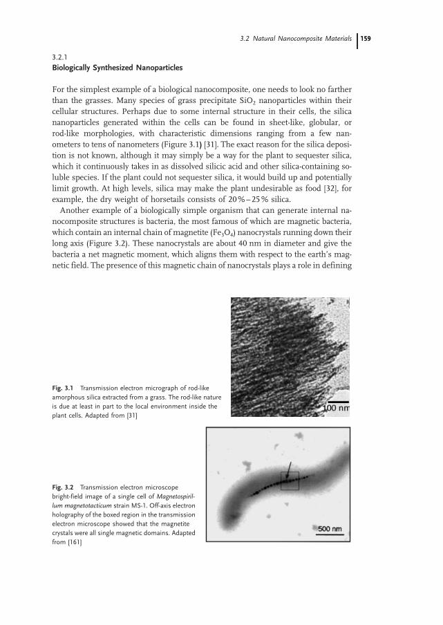
3.2.1
Biologically Synthesized Nanoparticles
For the simplest example of a biological nanocomposite, one needs to look no fartherthan the grasses. Many species of grass precipitate SiO2 nanoparticles within theircellular structures. Perhaps due to some internal structure in their cells, the silicananoparticles generated within the cells can be found in sheet-like, globular, orrod-like morphologies, with characteristic dimensions ranging from a few nan-ometers to tens of nanometers (Figure 3.1) [31]. The exact reason for the silica deposi-tion is not known, although it may simply be a way for the plant to sequester silica,which it continuously takes in as dissolved silicic acid and other silica-containing so-luble species. If the plant could not sequester silica, it would build up and potentiallylimit growth. At high levels, silica may make the plant undesirable as food [32], forexample, the dry weight of horsetails consists of 20%–25% silica.Another example of a biologically simple organism that can generate internal na-
nocomposite structures is bacteria, the most famous of which are magnetic bacteria,which contain an internal chain of magnetite (Fe3O4) nanocrystals running down theirlong axis (Figure 3.2). These nanocrystals are about 40 nm in diameter and give thebacteria a net magnetic moment, which aligns them with respect to the earth’s mag-netic field. The presence of this magnetic chain of nanocrystals plays a role in defining
Fig. 3.1 Transmission electron micrograph of rod-like
amorphous silica extracted from a grass. The rod-like nature
is due at least in part to the local environment inside the
plant cells. Adapted from [31]
Fig. 3.2 Transmission electron microscope
bright-field image of a single cell of Magnetospiril-
lum magnetotacticum strain MS-1. Off-axis electron
holography of the boxed region in the transmission
electron microscope showed that the magnetite
crystals were all single magnetic domains. Adapted
from [161]
3.2 Natural Nanocomposite Materials 159159
the direction of locomotion. Because an individual bacterium, on average, points in aspecific direction, as it moves it continuously explores fresh territory. In contrast, themovement of a bacterium lacking a directing force follows a randomwalk, resulting ina substantially lower probability for movement into fresh territory. Besides the Fe3O4-containing bacteria, other bacteria deposit chains of nanoparticles of the magneticmineral greigite (Fe3S4) within themselves. This mineral chain appears to serve thesame function as the Fe3O4 chain in the previous bacteria.
3.2.2
Biologically Synthesized Nanostructures
Biological organisms commonly synthesize nanostructured and nanocomposite ma-terials of much greater complexity than nanoparticles. These structures can come inmany forms, ranging from needles and plates to complex 3D nanostructures, and canexhibit many unique and interesting mechanical, chemical, and optical properties.Although simplifying all biological nanostructure formation routes into a single me-chanism is not possible, several general synthetic tenets tend to hold true. The first isthat the biological structure forms first, and then the inorganic phase begins to form.Although truly cooperative assembly is possible, it is much more common that theorganic matrix forms first, regulating the growth of the inorganic material. We shouldkeep in mind, however, that the organic matrix is plastic and can deform or reshape inresponse to the growing inorganic material.Besides forming nanoparticles, bacteria can form more complex nanostructures.
Bacteria in general are responsible for a vast amount of mineral deposition and infact can contribute greatly to mineral deposits on the bottoms of lakes and other aqua-tic environments. Mineral formation in the vicinity of bacteria is generally driven by abiologically induced change in the pH or ionic strength around individual bacteria.This change in the local environment reduces the solubility of certain mineral com-pounds, leading to precipitation of minerals. Generally, this results in an unfeaturedmineral, so is not of interest here. However, in specific cases, the structure of theprecipitated mineral is highly regulated by proteins on the surface of the bacteria,resulting in the formation of complex nanostructures. Specifically, some bacteriahave on their exterior a layer of proteins called an S-layer. As these bacteria re-spire, the local pH and ionic strength change, driving, for example, the mineralizationof gypsum (CaSO4). Rather than being deposited as an unfeatured solid on the exteriorof the bacteria, the growing gypsum is templated by the organic S-layer into a complexnanostructured form that very closely replicates the structure of the protein S-layer(Figure 3.3) [33, 34]. The exact mechanism of the mineral templating is notknown, but clearly preferred sites must exist on the S-layer for heterogeneous nuclea-tion of mineral, or a regular structure would not form. As these mineral nuclei grow,they impinge on one another, forming a thin, periodically structured film of gypsum.One reason for the complexity of this structure is that the resulting pores in the in-organic layer may allow the bacterium to exchange nutrients with its surroundingseven after the mineral phase forms. If the gypsum had formed as a dense solidfilm, it would rapidly stop the bacterium’s respiration, thus killing it.
3 Natural Nanobiocomposites, Biomimetic Nanocomposites, and Biologically Inspired Nanocomposites160

Although this specific S-layer templated structure as yet has no known applications,inorganic nanostructures of these length scales are of great interest for many high-technology applications. Patterning on these length scales is exceedingly difficult,so if bacteria could be genetically engineered to express proteins that result in S-layershaving technologically significant nanostructures, there would be the potential to bio-mineralize materials for advanced applications. In fact, initial strides have been madein this regard and are covered later in this chapter.Higher organisms also generate inorganic/organic composite structures. An excel-
lent example is the sea urchin. The sea urchin spine is a single crystal essentiallycomposed of calcite, containing only about 0.02% glycoproteins trapped within thecrystal lattice of the spine [35]. However, this very small amount of organic matterleads to the extraordinarily high toughness and unique fracture properties of thespine. The spine is much tougher than a synthetic equivalent composed of polycrystal-line or single-crystalline calcite. Most surprising is the fracture mode of the spine.Rather than fracturing along a specific crystallographic direction, as occurs formost single crystals, it fractures with conchoidal cleavage, that is, with a smoothrounded fracture surface, similar to that observed for glassy materials (Figure 3.4).The fact that it is a single crystal but does not fracture along any specific crystallo-graphic direction is quite unlike almost all other crystalline ceramic materials. Themechanism for the toughening is still unknown but is clearly due at least in partto the nanoscale dispersion of protein molecules in the crystal lattice.
Fig. 3.3 Transmission electron micrograph of (left) bacterial S-layer, which
serves as a protein template for the formation of (right) a thin film of me-
sostructured gypsum. Adapted from [33]
Fig. 3.4 Scanning electron micrograph of the fracture
surface of a single-crystal spine from a sea urchin, demon-
strating conchoidal cleavage. Adapted from [35]
3.2 Natural Nanocomposite Materials 161161

Another sea creature that creates an organic/inorganic composite that is vital to thecreature’s survival is the abalone, as already mentioned. The nacreous (mother-of-pearl) layer of the abalone shell consists of alternating layers of 500-nm-thick arago-nite platelets and 30-nm-thick sheets of an organic matrix (Figure 3.5). The matrixforms first, then the mineral plates develop between the layers. The matrix defines thethickness of the crystals, and certainly also adds to the strength of the composite struc-ture by forcing fractures to dissipate their energy as they travel a tortuous path throughthis elastic structure. The matrix also controls the crystallographic orientation of themineral plates, which must also be important for strength. The resulting compositestructure has a fracture toughness that is about 3000 times greater than that of inor-ganic aragonite [32]. Along with defining the size and shape of the aragonite plates, theorganic matrix also likely serves to define their crystallographic orientation. The me-chanism for formation of nacreous aragonite is not entirely clear, although it is knownthat the organicmatrix forms first into a hollow layered structure, and then the voids inthis structure are mineralized.Another excellent example of a biological nanocomposite with complex structure
and function is bone. Bone must perform multiple functions. It must have highstrength, yet low weight; it must support remodeling in response to applied stres-ses, yet not deform under applied stress; it must contain pores to allow oxygenand nutrients to reach the cells within the bone, yet these same pores cannot leadto fractures; finally, it must act as a reservoir for minerals, but not allow itself to de-mineralize and thus weaken. Bone exists in several forms; lamellar bone provides thestructural properties of long bones in mammals and other species and is the subject ofthe following discussion, adapted from [36, 37] (Figure 3.6). The basic structure ofbone is a mineralized collagen fibril consisting of on average 65% mineral, the re-mainder being organic material and water. The collagen phase of bone is composedof individual fibrils about 80–100 nm in diameter. These fibrils are in turn composed
Fig. 3.5 Scanning electron micrograph of a fracture surface of the nacre of the
red abalone, showing a side view of the aragonite tablets. Adapted from [162]
3 Natural Nanobiocomposites, Biomimetic Nanocomposites, and Biologically Inspired Nanocomposites162

of assemblies of a triple helix of polypeptide chains with an average diameter of 1.5 nmand length around 300 nm. The internal arrangement of this triple helix structure inthe collagen fibril is not random: the helix aligns with its long axis parallel to the longaxis of the bone and has additional fine structure. The mineral phase of the bone,
Fig. 3.6 The 7 hierarchical levels of organization of the bone family of ma-
terials, according to Weiner [37]. Level 1: Transmission electron micrographs of
individual mineral crystals from human bone (left side) and an unmineralized,
unstained collagen fibril from turkey tendon embedded in vitreous ice (right
side). Level 2: Transmission electron micrograph of a mineralized collagen fibril
from turkey tendon. Level 3: Transmission electron micrograph of a thin section
of mineralized turkey tendon composed of multiple fibrils. Level 4: Four fibril
packing motifs found in the bone. Level 5: Scanning electron micrograph of a
single osteon from human bone. Level 6: Light micrograph of a fractured
section through a 5500 year old fossilized human femur. Level 7: Whole bovine
bone (scale: 10 cm). Adapted from [37]
3.2 Natural Nanocomposite Materials 163163

carbonated apatite (Ca5(PO4,CO3)3(OH)), forms as 50-nm-long, 25-nm-wide plateletsthat are on average 1.5–4 nm thick (Figure 3.7). These platelets lie within the collagenfibrils, with only a small number of polypeptide chains between each platelet. The longaxis of the platelets is generally parallel to the outer surface of the bone, most likely tomaximize the compressive strength of the bone.The mineral structure forms in bone after the collagen fibrils form. However, as the
mineral forms, the collagen structure may reorganize to some extent. Thermodyna-mically, the carbonated apatite platelets should coarsen into larger single crystals overtime (Ostwald ripening), but clearly this is prevented by the collagen matrix. Thus,although the collagen matrix reorganizes to some extent, it clearly cannot be comple-tely pushed out of the way by the growing mineral. This level of control by biology overstructural development during mineralization currently exceeds that found in syn-thetic materials. Additionally, after a bone is broken, new structures form which gen-erate material that is as strong as the original bone; yet, the mineralization processstops when the healing process is complete. Bone thus is an excellent example ofa self-healing biological nanocomposite in which an organic host phase is formed,followed by highly regulated mineralization processes. The mechanism for this pro-cess is not entirely clear, but substantial strides in understanding it are being made.Clearly, biological systems can create a tremendous diversity of inorganic materials;
however, biological systems are also very limited in terms ofmaterial selection. Metals,as well as many polymers, semiconductors, and ceramics cannot be synthesized bybiological processes, because the precursors are not available in the natural environ-ment, the materials or precursors are toxic, and/or the product is not stable in the
Fig. 3.7 Transmission electron micrograph of a fractured piece of mineralized
bone from a 50-year-old human male femur. (a) Many mineral crystals are
oriented edge-on and are parallel to the long direction of the collagen fibrils. (b)
Higher magnification view of the bone fragment at the location in (a) marked
with an arrowhead. Here, crystals are oriented face-on. The flat, plate-like nature
of the mineral crystals in bone can be observed in these figures. Adapted from
[163]
3 Natural Nanobiocomposites, Biomimetic Nanocomposites, and Biologically Inspired Nanocomposites164

presence of water and/or oxygen. Because of this, there is serious interest in usingelements of biological systems to create synthetic nanocomposites from materialsnot found in biology, thus achieving the best of both the biological and syntheticworlds.
3.3
Biologically Derived Synthetic Nanocomposites
Because of the limited variety of materials available by purely biological routes, there isgreat interest in utilizing the sophistication offered by biological systems in concertwith synthetic procedures to create materials with otherwise unobtainable nanostruc-tures and thus, potentially, unique properties. Biology offers a unique selection ofbuilding blocks that would be difficult or impossible to synthesize in the labora-tory. These include proteins, DNA, RNA, and small but highly functional molecules.
3.3.1
Protein-Based Nanostructure Formation
As already mentioned, protein S-layers on the surface of bacteria create complex na-nostructures. The protein S-layer present on the surface of some bacteria has now alsobeen used to create entirely synthetic nanostructures. The diversity of S-layer struc-tures, coupled with the potential for chemical functionalization, make them ideal start-ing points for nanostructure synthesis. To review, S-layers are 2D protein crystals thathave oblique, square, or hexagonal lattice symmetry with lattice constants between 3and 30 nm. Interesting for potential nanostructure formation, and to enable bacterialrespiration, S-layers almost universally contain pores of identical size and identicalsurface chemistry – properties that make S-layers useful for nanostructure and na-nocomposite fabrication. In an early example [38, 39], an S-layer was used to templatea periodic structure into a thin metal film. Specifically, a 1-nm-thick metal (Ta/W) filmcontaining 15-nm holes periodically arranged in a triangular lattice with a lattice con-stant of 22 nm was created by S-layer templating. This was accomplished by first de-positing a suspension of S-layer fragments onto an amorphous carbon support film.After S-layer deposition, a 1.2-nm thick film of Ta/Wwas evaporated onto the S-layer atan angle of 408 from the normal of the substrate surface. When examined in the trans-mission electronmicroscope (TEM), the resulting film shows contrast indicating somethickness variation in the metal, but the contrast is not significant. To improve thecontrast and to open up holes in the metal film, the film was argon-ion-milled fora short time. The result was a metal film that contained a periodic array of holeswith the same symmetry as in the S-layer template [38, 39]. This work was donemore than 15 years ago, yet creating such a nanostructure today would still be a chal-lenge, even with a modern e-beam lithography system.Much more recently [13], an S-layer was used to create nanostructured semiconduc-
tor films. The S-layer in this study had an oblique 2D lattice (space group p1; a = 9.8
3.3 Biologically Derived Synthetic Nanocomposites 165165

nm, b = 7.5 nm, h = 808). Depending on the mechanism of S-layer deposition, either itsnegatively charged inner face or its charge-neutral outer face was exposed to a 10mMCdCl2 solution. After drying, the cadmium-ion-doped S-layer was exposed to H2S gas,resulting in formation of a nanocrystalline film of the semiconductor CdS on the S-layer. In the TEM, the CdS film exhibited a superlattice structure that was a direct copyof the structure of the S-layer [13]. The S-layer may have survived the entire process,and thus the actual mineral structure formed may be a nanocomposite of CdS andprotein. It is still unclear what applications might be found for such materials,although robust metal or semiconductor nanoporous structures may find applicationas filter membranes, sensors, and optoelectronic devices.Another protein assembly that has been used to form nanocomposite materials is
ferritin (Figure 3.8). In its native form, ferritin consists of a supramolecular arrange-ment of proteins around an iron oxide core. The iron oxide core can be selectivelydissolved without damaging the structure of the protein shell, yielding a hollowball of protein about 10 nm in diameter. The demineralized protein (apoferritin)can be refilled with iron oxide, demonstrating that its structure was not greatly af-fected by the demineralization process. Interestingly, apoferritin can also be filledwith other mineral nanoparticles. In one example [32], the iron oxide core of ferritinwas converted to FeS by treating the ferritin withH2S. Nanoparticles ofMnOOH, UO3,Fe3O4, and CdS can also be formed inside apoferritin through the appropriate chemi-
Fig. 3.8 Transmission electron
micrographs of magnetite
(Fe3O4)- and maghemite (c-Fe2O3)-filled ferritins. (a) 260 Fe
atoms/molecule, unstained;
only the discrete electron-dense
inorganic cores can be seen. (b)
260 Fe atoms/molecule, after
staining with uranyl acetate,
showing encapsulation of inor-
ganic cores by intact protein
shell (white halo around each
particle). (c) 530 Fe atoms/mo-
lecule, unstained. (d) 1000 Fe
atoms/molecule, unstained. (e)
2040 Fe atoms/molecule, un-
stained. (f) 3150 Fe atoms/mo-
lecule, unstained. Scale bars in
all figures = 50 nm. Adapted
from [164]
3 Natural Nanobiocomposites, Biomimetic Nanocomposites, and Biologically Inspired Nanocomposites166

cal treatment. Because the protein shell is not disrupted by the mineralization process,the final product is truly a nanocomposite of protein and inorganic material. See [32]for an extended discussion of the use of apoferritin as a template for synthesizingnanocomposite materials.
3.3.2
DNA-Templated Nanostructure Formation
DNA offers great potential as a building block for nanocomposite materials. It can betethered to a wide range of substrates, can direct assembly with specificities that greatlyexceed that of any synthetic molecule, is relatively robust, can be synthesized in re-latively large quantities, and can be functionalized with tags such as fluorescent mo-lecules to enable rapid detection of binding events.The use of DNA to assemble and create nanostructures and nanocomposite materi-
als is only in its infancy, but even the preliminary work done so far indicates the greatpotential of DNA-based assembly techniques. A few of the approaches that have beenstudied to date include the mineralization of DNA, the use of DNA to assemble na-noparticles, and the use of DNA to assemble much larger colloidal particles. Thesethree approaches are outlined in this chapter; however, the number of possibilitiesis vast, and significant work on DNA-mediated assembly of nanostructures is cur-rently being done.The possibility of using plasmid DNA as a template for mineralization was first
explored in 1996 [40]. In this work, single strands of a 3455-basepair circular plasmidDNA were mineralized with CdS nanoparticles, by mixing the plasmid and cadmiumperchlorate in solution, followed by spin coating this solution onto a polylysine-coatedglass slide. The DNA/cadmium perchlorate-coated glass slide was then exposed toH2S, converting the cadmium perchlorate to CdS, which preferentially mineralizedthe DNA. This procedure results in ring-like structures consisting of DNA embeddedwithin a 5–10-nm-thick CdS strand that can be directly observed in the TEM (Figure3.9). The diameter of the ring formed by the CdS-encrusted DNA is directly related tothe diameter of the DNA plasmid, and the thickness of the CdS/DNA compositestrand is about 10 nm. This represents the first example of DNA templating of semi-
Fig. 3.9 Transmission electron micrograph of a
nanostructure obtained by mineralization of a cir-
cular plasmid DNA with CdS nanoparticles. The
ring diameter closely matches the predicted dia-
meter of the plasmid DNA. Adapted from [40]
3.3 Biologically Derived Synthetic Nanocomposites 167167

conductors but, given the vast array of structures that can be formed from DNA,should not be the last.Another example of DNA-based nanostructure development can be seen in the work
on DNA-based nanoparticle assembly. Several approaches have been explored, withthe majority based on the Watson–Crick base-pairing of DNA strands attached tovarious nanoparticles. The first approach involved the functionalization of gold nano-particles with multiple strands of thiol-terminated type-A or -C DNA in separate reac-tions [41] (where ‘type’ is used as a label for different nucleotide sequences). The thiolterminal group is important, because it enables covalent attachment of the DNA strandto the gold nanoparticles. Importantly, the A and C strands were designed so that theywould not hybridize. The result, after mixing the solutions of each kind of DNA-func-tionalized nanoparticles, is a simple mixture of DNA-functionalized gold of type A andDNA-functionalized gold of type C. Then a single strand of DNA with one end com-plimentary to the type-A DNA and the other end complimentary to the type-C DNAwas added. We label this strand B-D. Upon hybridization of the B-D strand with bothnanoparticles of type A and nanoparticles of type C, a DNA-linked aggregate of na-noparticles was formed. Aggregate formation is thermally reversible by increasingthe temperature above the melting point of the DNA, at which point the strands de-hybridize. The assembly could be monitored by UV/visible spectroscopy, because theUV/visible absorption of gold nanoparticles changes greatly when they are close to-gether, due to changes in the surface plasmon.The formation of controlled aggregates, although interesting, is really a starting
point for the creation of much more complex structure through a marriage of biolo-gical macromolecules and synthetic materials. In addition to placing multiple DNAmolecules on a nanoparticle, it is possible to place a single or a finite number ofDNA molecules on a nanoparticle. However, this requires a significant degree of syn-thetic effort, because one usually starts with a population of nanoparticles with variousnumbers of attached DNA molecules. Through careful separation, nanoparticles withexactly one or exactly two single-stranded DNA molecules on their surface can berecovered. These DNA-functionalized particles can then be assembled in highly con-trolled fashions through DNA hybridization reactions, by adding single-stranded DNAthat is complimentary to the single-stranded DNA on the nanoparticles (Figure 3.10).This is similar to the approach used tomake DNA-linked aggregates; however, becauseeach nanoparticle contains only one DNA strand, not multiple strands, the result afterhybridization is not the formation of an aggregated structure, but rather, individualdimers of gold nanoparticles. Trimers of gold nanoparticles were also created by asimilar approach, except that nanoparticles with one strand of DNA of three differentsequences was mixed with a strand of DNA complimentary to all three of the DNAstrands on the surface of the nanoparticles [42, 43].Recently, it was demonstrated that DNA can assemble much larger colloidal parti-
cles into 3D assemblies of controlled shape. The basic approach is very similar to theassembly of nanoparticles; however, here the results after hybridization are assembliesof colloidal particles with defined connectivity [44].The overall power of DNA-based assembly of nanostructures is based on several
powerful aspects of DNA hybridization. First, hybridization is reversible with tempera-
3 Natural Nanobiocomposites, Biomimetic Nanocomposites, and Biologically Inspired Nanocomposites168

ture; thus it is possible to anneal structures that at least partially eliminate kinetic trapsthat may be present in the assembly process. For example, if during nanostructureassembly, a particle does not hybridize in the correct location, the structure can begently heated, releasing the particle, and then the particle can be retrapped by coolingbelow the melting point of the DNA. Second, DNA hybridization is very specific. Un-like most organic linking chemistries, which cannot distinguish small changes inmolecular structure, DNA can be designed to hybridize only to its exact complimen-tary strand. Thus it may be possible to combine many DNA-functionalized nanopar-ticles into very specific arrays by hybridizing to a long strand of DNA that is encoded soas to react with each DNA functionalized nanoparticle at only a very specific location.
3.3.3
Protein Assembly
To achieve a level of complexity similar to what can be obtained by DNA-based assem-bly, one can engineer or select biological organisms that recognize and bind with highspecificity to specific minerals, semiconductors, and metals. In the first example [45],Escherichia coli containing genetic sequences specific for recognizing and binding ironoxide but not other metal surfaces was identified and multiplied. Bacteria that would
Fig. 3.10 DNA allows for precise manipulation of
the order and spatial arrangement of nanoparticles.
The large and small nanoparticles can be designed
to hybridize or react with a single site on the DNA
backbone. See examples A, B, and C on the left and
the resulting nanostructures on the right. Adapted
from [43]
3.3 Biologically Derived Synthetic Nanocomposites 169169

specifically adhere to iron oxide were identified via serial enrichment from a popula-tion of bacteria. The experimental procedure was as follows: A population of geneti-cally diverse E. coli was exposed to iron oxide particles. The bacteria that bound to theiron oxide were collected, and the remainder were discarded. After repeating this pro-cedure for several generations, bacteria with high degrees of specificity for iron oxidewere obtained. The reason only some of the bacteria bind iron oxide is that E. coli, likemany other bacteria, express proteins on their outer surface whose sequences are afunction of the unique genetic makeup of the bacteria. By starting with a library of107 E. coli that express surface proteins of slightly different sequences, the probabil-ity that at least one of the E. coli has a highly specific protein is reasonable. Throughenrichment, it is possible to extract and multiply just those bacteria that bind to thesurface of interest.It is also possible to select for protein sequences that attach to specific metal sur-
faces, and presumably also to metal nanoparticles. Through such biological experi-ments, a library of 107 different polypeptides 14 or 28 amino acids long was cre-ated. Then, the polypeptides that adhere to the metal surface were isolated, and theirsequences were determined [46]. This approach is exceedingly powerful because of thevast number of different molecular sequences that can be studied in parallel in a singleexperiment.From a technological standpoint, it is interesting to consider the possibility of re-
cognizing semiconductor surfaces and semiconductor nanoparticles with this proce-dure. If an appropriate genetic sequence can be identified, it would be possible toassemble nanoparticles via biological organisms that are designed to present the ap-propriate biological macromolecules on their surface. Phage display enables the simul-taneous testing of many peptide sequences for specificity to a given surface. A phagelibrary containing 109 polypeptide sequences was exposed to a surface, and all thephages that did not bind to the surface were washed away. The phages that stuckwere then removed from the surface by lowering the pH and were amplified by in-fecting E. coli bacteria with them. This process was repeated until only phages thatstuck strongly to the surface were present. The DNA of these phages was then se-quenced to determine the specific peptide sequence(s) that bind with such high affi-nities to the specific surface of interest [47].A phage that identifies and binds to a surface of a specific material also binds
strongly to nanoparticles of this material. The result of mixing a nanoparticle-bindingphage with nanoparticles is ‘decoration’ of the phage with nanoparticles, which occursonly at the end of the phage that contains the specific binding polypeptide, and no-where else on the phage [48]. Depending on the experimental conditions and phagedesign, it may even be possible to bind single nanoparticles to an individual phage or toassemble the nanoparticles into defined structures, although in the present state of theart, multiple nanoparticle are bound in a fairly random fashion to each phage.
3 Natural Nanobiocomposites, Biomimetic Nanocomposites, and Biologically Inspired Nanocomposites170
3.4
Biologically Inspired Nanocomposites
The properties of biocomposites and synthetic pathways for their formation have in-spired wide ranging research. However, early on it was recognized that it is not alwaysnecessary or even desirable to use biologically derived materials for many applicationsand that it may be possible simply to use biology as an inspiration for totally syntheticnanocomposite systems. It is interesting to consider biological systems as an inspira-tion for nanocomposite materials, because biological systems exhibit many character-istics that would be attractive in synthetic materials, but it is also clear that direct mi-micking of biology will be limited to a specific small subset of materials and to specificnanostructures. However, many lessons can be learned from biology on how to formcomplicated nanostructures and on the potential properties of these synthetic nanos-tructured materials, should one be successful in synthesizing them. Of course, justbecause a synthetic material resembles a natural process and the process of formingthat material resembles a natural synthesis does not always mean that the scientistsand engineers who performed the work were inspired by biology. Often it is not statedwhether biology was an inspiration for the work, and thus some care must be takenbefore assuming that, just because something appears biologically inspired, it is bio-logically inspired. In this chapter, I do not attempt to make this distinction and bynecessity assume that, if the work has a biological analog, then it can be considered‘biologically inspired’, although certainly in some cases this assumption may bewrong. In this chapter I take the liberty to lump such work under the heading of‘Biologically Inspired Nanocomposites’.Much can be learned from biological systems to further the development of syn-
thetic approaches to the formation of complex inorganic structures. Each of the routesto nanostructure formation that is discussed in this section – liquid crystal templating,colloidal particle templating, block copolymer templating, and surfactant-inorganicself-assembly (mesoporous silica being the most famous of this approach to nanos-tructure formation) – invokes many of the tenets of biologically directed mineralgrowth. As already discussed, biological systems rely on self assembly and mineraliza-tion in the synthesis of hard inorganic structures such as shells, teeth, and bone [11],and their approaches to materials fabrication can provide guidance and direction tosynthetic systems. Often, the term ‘biomimetic’ has been applied to any approachusing self assembly in the synthesis of nanocomposite materials. As mentionedabove, biological systems do indeed use self-assembling molecules, and high levelsof molecular organization are a very important part of an organism’s inorganic struc-ture development. However, it would be naive to expect to simulate this process in thelaboratory except on the most basic level. Biological processes are extremely dynamic,involving huge numbers of very specific proteins and other molecules being generatedand transported to very specific locations, with temporal control. The best syntheticsystems are indeed very simple approximations of living systems and generally aremuch too simple to be considered to be truly mimicking biology. Although the syn-thetic systems are only simple approximations of life, still much can be learned byattempting to mimic living systems [8], even if biomimetic is perhaps not the best
3.4 Biologically Inspired Nanocomposites 171171

term. For example, many attempts centered around the synthesis of mineral phases ina self-organized matrix have indeed mimicked the mineralization processes of manybiological systems. Examples of matrix-mediated biological mineralization processesinclude the reliance of bacteria, plants, shells, and even mammals on organicallymediated growth of mineral phases to eliminate byproducts (bacteria and plants)[31, 33, 34], create exoskeletons (shells) [49], and grow teeth (mammals) [35]. If duringthe synthetic process, organic molecules are incorporated into the mineral phase, theresulting material may resemble the spicule of a sea urchin, which contains much lessthan 1% protein intercalated into the crystal lattice [35].Despite the low degree of sophistication of synthetic systems, they do have very
distinct advantages over biologically based schemes. Biological systems operatewith only a limited subset of elements and compounds, but synthetic systems canbe designed to use a wider range of elements and compounds, many of which wouldbe toxic to most living organisms. Biological systems form and operate near roomtemperature in the presence of water and oxygen (for the most part), but syntheticsystems can be formed and operate under a wide range of temperature and condi-tions. Finally, biological materials generally take days to years to form, but syntheticsystems may be formed rapidly. For biology, systems that form slowly in response toexternal stimuli have significant advantages, for example, bone remodels to meet thedemands of applied loads. However, in general, the long time scales required for for-mation of biological nanocomposites limit the application of direct biological synthesisof engineering materials to a few very specific cases.Through self-assembly of organic molecules, biological systems have succeeded in
synthesizing a wide range of composite and inorganic nanostructures. Biological sys-tems contain large quantities of lipids, or soap-like molecules, which self-assemble(along with many other biological macromolecules, including proteins) to form theexternal membranes of cells, as well as smaller vesicles within the cell. These mem-branes serve to protect the interior contents, as well as to provide synthetic microreac-tors for biological processes. The concept of performing syntheses in self-assembledmicroreactors is in this sense biologically inspired, has been exploited by many re-searchers to create nanoparticles and composite nanostructures, and is the topic ofthis section.The simplest examples of nanomaterials are zero-dimensional materials, known as
‘nanoparticles’. The study of small semiconductor particles in general is of significantinterest, because the electronic and optical properties of semiconductor nanoparticleschange drastically as the characteristic dimension of a particle is reduced to the na-noscale regime, largely due to the quantum confinement of electrons within the par-ticle, although surface-area effects may also play a role (Figures 3.11, 3.12) [50–52].The most popular nanoparticles for basic studies have been II–VI semiconductorparticles, because of their scientifically interesting and technologically important prop-erties. In this context, synthetic methodologies for the formation of metal sulfide andselenide quantum dots and their assembly into higher-order structures have beenwidely studied [53–57]. For nanostructuring to dominate the properties of metal sul-fides and other semiconductors, it is generally necessary for the characteristic dimen-sion of the nanoparticle to be <10 nm [58]. Semiconducting nanoparticles are gener-
3 Natural Nanobiocomposites, Biomimetic Nanocomposites, and Biologically Inspired Nanocomposites172

ally synthesized through one of three routes. The first, grinding of large chunks israrely done for nanoparticle preparation, because the grinding process is poorly regu-lated, generally generating a very polydisperse population of particles, and grindingintroduces too many contaminates for most applications. The other two methods,gas-phase and solution-phase synthesis, are much more common. Gas-phase synth-esis is essentially a vaporization and condensation process – a crucible containing thedesired semiconductor (or other material) is heated until it starts to sublime, and thenan inert carrier gas is flowed over the material. The carrier gas then heads into a coolregion where the gaseous semiconductor atoms or molecules condense into nanopar-ticles and are collected [59]. Although this method is fairly versatile, it operates onlyunder conditions of high temperature and vacuum and generally produces solid sphe-rical particles.Solution-based synthetic routes for nanoparticle formation have ranged from simple
precipitation reactions to much more complex self-assembly-based routes. In general,simple precipitation results in agglomerates of nanoparticles, and the size distributiongenerally varies widely. These problems led to research into synthetic procedures thatwould result in nanoparticles that are stable against aggregation and have narrow sizedistributions. A primary route to preventing both these problems is to use self-assem-bly-based techniques, which inmany respects resemble nanostructure development inbiological systems, including biomineralization, cell membrane development, andother biological structure formation. Solution-phase synthesis of semiconductors isoften preferred over other techniques, because it is generally mild (even being carriedout at room temperature and pressures) and can be used to create reasonable volumesof materials. Solution-phase synthesis has been widely used to grow semiconductor
Fig. 3.11 Theoretical calcula-
tion of band-gap energy as a
function of particle diameter for
several different semiconduc-
tors. Adapted from [58]
3.4 Biologically Inspired Nanocomposites 173173

quantum dots, yielding particles with low polydispersities and novel optical properties[50, 51, 56, 57, 60]. Solution-based chemical syntheses are very attractive because theyallow for direct control over the actual concentrations of the chemical precursors. De-pending on actual conditions, it is even possible to cap the surface of the particles withorganic molecules, which allows for further solution-based processing [53, 55].The more conventional route to creating nanostructured materials is of course
through top-down lithographic methods. Some examples of top-down techniquesfor generating very small features are extreme UV (k << 200 nm) lithography [61,62], electron beam writing [63], focused ion-beam lithography [64], x-ray-lithography[65], scanning probe lithography [66], and microcontact printing [67]. In general, allthese techniques can form structures on the scale of tens to hundreds of nanometers,although generally only on very flat substrates, and they can be quite slow and oftenvery expensive. The self-assembly-based route to nanostructure formation has the sig-nificant advantage that it is not limited to feature generation on flat surfaces, and it canbemassively parallel. Of course, the general problemwith self-assembly is that it is notpossible to highly regulate the exact spatial position of the nanostructure, and thus weare still many years away from creating highly functional self-assembled electroniccircuits.In the micellar routes to nanoparticle formation, micelles are self-assembled from
surfactant molecules and a solvent that contains at least one of the precursors for theinorganic nanoparticles in solution. The result is a solution that contains vast numbersof discrete nanoreactors which individually contain only a finite number of precursorspecies for the inorganic phase.When these ions are converted tomineral, generally byreduction or oxidation, the result can be one nanoparticle per micelle. The polydisper-sity in nanoparticle diameter is thus directly related to the polydispersity in the initialmicelle size. If it were possible to create a suspension of monodisperse micelles, itwould be a straightforward process to create nanoparticles with a very narrow size
Fig. 3.12 Cd3P2 quantum dots. Particle size increases in the direction of the
arrows. The white particles are about 1.5 nm, and the black particles are larger
than 5 nm. Adapted from [50]
3 Natural Nanobiocomposites, Biomimetic Nanocomposites, and Biologically Inspired Nanocomposites174

distribution. Taking a lesson from biology, this might be possible through the use ofcomplex macromolecules that organize into particles of only a specific size. A verygood biological example of a potential nanoreactor with a tight size distribution isa virus particle. It may be possible to use virus particles to synthesize nanoparticleswith tight size distributions if a way to load the interior of the virus particles withprecursors for nanoparticles can be developed.Most of the early nanoparticle synthesis routes produced solid semiconductor par-
ticles with morphologies never far from spherical. The creation of nanoparticles withcomplexmorphologies ismost interesting, because even such sophisticated patterningtechniques as e-beam lithography are limited to 10-nm features, which are often toolarge to result in the desired quantum confinement and other properties [63]. Nano-particles having certain complex morphologies cannot be created through e-beam pat-terning or other top-down processing routes. The possibility of generating complicated
Fig. 3.13 Transmission electron micrograph of nanocrystalline CdS structure
grown under an arachidic acid monolayer at room temperature. Scale bar = 200
nm. Adapted from [165]
3.4 Biologically Inspired Nanocomposites 175175

morphologies was examined in studies of CdS synthesized under Langmuir mono-layers, in which dendritic structures were generated (Figure 3.13) [68]. Subse-quently, a range of strategies have resulted in rod-like and even complex nanoparticleswith complex morphologies that are based on self-assembly regulating the growth ofsemiconductor particles.As examples of self-assembly processes which create nanoparticles with complex
shapes, Alivisatos and coworkers [69, 70] demonstrated the formation of CdSe nanor-ods with aspect ratios of 30:1, as well as arrow-, teardrop-, tetrapod-, and branchedtetrapod-shaped nanocrystals of CdSe (Figure 3.14). These highly shaped nanoparti-cles result from using a mixture of hexylphosphonic acid and trioctylphosphine oxideas passivating agents in the synthesis. Apparently, it is possible to block the growth ofspecific crystallographic faces while encouraging the growth of other faces. Thus, par-ticles that have one crystallographic direction as their long axis, and their short axis asanother crystallographic direction can be formed. The advantage of high aspect ratioparticles over normal, spherical particles has not yet been proven, but the electronic orphysical properties of the particles might be impacted by the change in shape. Inaddition, the particles might be able to self-assemble into higher-order structures be-cause of their high aspect ratios; for example, they may form liquid crystalline phases,much like molecules with high aspect ratios [69, 70].Semiconductor nanostructures may also have potential nonquantum confinement-
based properties not found in the bulk equivalent. Besides quantum confinement, oneway to greatly modify the properties of nanostructured semiconductors may be todesign synthetic methodologies that result in dispersion of organic molecules withinthe inorganic phase at the molecular level. These composite materials could exhibitnovel properties significantly enhanced over those of either the inorganic or organicphase alone, as has actually been observed in a wide range of materials. Compositematerials that are tougher [71–73], have increased thermal stability [74], are electro-nically more sophisticated [75,76], or have enhanced chemical selectivity [77] thaneither of the constituent parts have been created. Even without the incorporationof organic material, periodically nanostructured semiconductors have great potentialin solid-state science and technology, for example because of their potential for bothelectronic and catalytic activity. For example, a periodically nanostructured semicon-
Fig. 3.14 Examples of CdSe nanoparticles with complex shape and form that
can be created by solution synthesis from a mixture of surface passivating
agents. Adapted from [70]
3 Natural Nanobiocomposites, Biomimetic Nanocomposites, and Biologically Inspired Nanocomposites176

ductormight behave as an array of antidots (amaterial with a regular array of scatteringcenters spaced closer than the mean free path of electrons traveling through them) [78,79]. A nanostructural material is necessary because, if the mean free path of the elec-trons is shorter than the spacing between the scattering centers, the antidot lattice doesnot operate. At high magnetic fields (>2 Tesla), quantum steps in the conductivity as afunction of electric field may be observed if the lattice spacing of the antidots is on theorder of the cyclotron diameter of the electrons. In contrast to forming a solid of quan-tum dots, the formation of an antidot lattice requires the semiconducting structures tobe continuous, with a periodic array of nanocavities.Early on, the greatest emphasis was on creating nanoparticles with narrow size dis-
tributions, not on creating superlattice structures. However, through careful control ofsize distribution and chemical functionality, CdSe nanocrystals, and now many othernanocrystals, have been observed to order into superlattice structures [55]. These struc-tures may present properties beyond simple quantum effects. The individual crystal-lites in this system do not form a continuous mineral structure, but are actually se-parated by thin layers of organic molecules, which are composed of the self-assem-bling molecules used in the synthesis to regulate the diameter and polydispersityof the particles. During synthesis, the organic self-assembles into a shell aroundthe nanoparticles, imparting organic solubility to the nanoparticles, which enablesthem to be processed similar to organic compounds. Because of the high degreeof regularity in size and shape, these organically coated nanoparticles assembleinto a crystal of nanoparticles with long range periodicity, much in the way that or-ganic molecules and atoms can crystallize.The next level of complexity in nanostructure formation is the creation of nanos-
tructures with complex, predefined morphologies. Here, the biological concepts ofself-assembly and nanostructure formation become most applicable. For example,in biology, it is common to have complex predefined structures on the nanometerscale, yet this length scale is exceedingly difficult to regulate in synthetic materials.However, if the power of self-assembly is coupled with the materials synthesis stra-tegies known today, there is great potential for the formation of complex compositenanostructures.Liquid-crystal templating of inorganic nanostructures, an approach in which the
periodic structure of liquid crystals is imparted to a mineral phase, is one suchroute. Liquid crystals present an ideal matrix for the creation of nanoscale compositematerials, because the characteristic 1–10 nm length scales most often expressed inliquid crystals are similar to the size scale of interest for semiconductor nanostruc-tures. Furthermore, the periodic structure in liquid crystals can be quite long-range, and thus the periodic nanostructure also has the potential for long-range or-der, which is of exceptional interest for many applications. A very important goalof several research groups is in fact the creation of long-range nanoperiodic orderin materials such as semiconductors through liquid-crystal templating.Semiconductors with long-range periodic composite structures could come in sev-
eral forms, for example as a particle containing a periodic array of embedded second-phase material, as a thin film with a periodic topography, or as a periodically porousmaterial. Highly porous, periodically nanostructured semiconductor particles could be
3.4 Biologically Inspired Nanocomposites 177177

quite interesting for solution-based chemistry. For example, the photochemical natureof their semiconducting phase and zeolite-like pore structure could make them highlyapplicable for photochemical degradation of toxic compounds or for performingshape-selective chemistry, that is, chemistry that operates only on molecules of spe-cific shape and size. Thin filmsmay be evenmore technologically important, given thewide range of potential uses for both supported and freestanding thin films. The abilityto predefine a nanoperiodic array of features in semiconductor thin filmsmay open upmany applications, including electronic devices, sensors, and filter membranes.Three-dimensional semiconductor structures may have unique optical or electronicproperties, depending on the characteristic length scale of the structure. As the lengthapproaches hundreds of nanometers, the materials may even exhibit photonic band-gap effects. Because direct top-down patterning of <10-nm-long nanostructures isdifficult or impossible, and the patterning of 3D nanostructures of almost any lengthscale is difficult, templating of nanostructures through self-assembly processes hassignificant promise. Essentially, self-assembly-based templating can take place ineither 2 or 3D, and the templating agent may or may not be removed, as desired.Here, we discuss several templating methodologies with potential for nanocompositeformation, the properties of such templatedmaterials, and their potential applications.
3.4.1
Lyotropic Liquid-Crystal Templating
Lyotropic liquid-crystal templating is an approach for nanostructure and nanocompo-site formation that utilizes the self-assembled structure of a liquid crystal to regulatethe structure of a growing inorganic material. When processed correctly, the structureof the inorganic phase directly replicates the structure of the liquid crystal; thus theliquid crystal is a ‘template’ for the inorganic. The most important aspect of liquid-crystal templating of inorganic material is the lyotropic liquid crystal; thus, we shouldto review some of the basics of lyotropic liquid crystals. Lyotropic liquid crystals arecomposed of at least two covalently linked components, one of which is usually anamphiphile, which is a molecule that has two or more physically distinct compo-nents, and the other a solvent. Typically, one of the components making up the am-phiphile is hydrophobic, and the other component is hydrophilic, as in common soaps,although this is not the necessary distinction. The dual solvent properties of an am-phiphile lead to the interesting self-assembly of these molecules in solution by meansthat include surface segregation, formation of micelles [80,81] and vesicles [82,83], aswell as the formation of a wide range of LC structures [84,85].Most amphiphilic molecules contain two or occasionally three segments, of which at
least one is water soluble. Clearly, if half a molecule dissolves in a solvent and the otherhalf does not, interesting self-assembled structures may result. Within the generalclass of amphiphilic molecules are four distinct subclasses: cationic, anionic, zwitter-ionic, and nonionic. Cationic, anionic, and zwitterionic amphiphiles all contain a for-mally charged polar moiety, typically called the head group, and a nonpolar moiety,typically termed the tail. As the names imply, cationic amphiphiles contain a cationic
3 Natural Nanobiocomposites, Biomimetic Nanocomposites, and Biologically Inspired Nanocomposites178

head group, such as a quaternary ammonium salt, and anionic amphiphiles, an an-ionic head group such as a sulfonate salt. Zwitterionic amphiphiles contain a headgroup having both positive and negative charge, for example trimethylammoniumphosphonate. Nonionic amphiphiles do not contain charged functional groups, butinstead contain polar segments such as oligo(ethylene oxide) or oligo(vinyl alco-hol). Examples of anionic and nonionic amphiphiles, sodium octanoate and oli-go(ethylene oxide) oleyl ether, respectively, are shown below.
Amphiphiles exhibit very rich, complex phase behavior as a function of solvent con-centration. In the dilute amphiphile limit, structures such as micelles form, and in theconcentrated amphiphile limit (even solvent free), some amphiphiles show liquid crys-talline or crystalline phases. Between these endpoints, a wide range of phases andstructures can form. A typical nonionic amphiphile, oligoethylene oxide (10) oleylether [(EO) 10 oleyl], forms micelles, micellar rods, and hexagonal, cubic, and lamellarliquid crystals as the amphiphile:water ratio increases. This rich self assembling be-havior occurs because the polar segment is readily solubilized by water, and the non-polar tail is not. For a single molecule in solution, other than curling up on its self(which is entropically very unfavorable), there is no physical way to reduce the unfa-vorable interactions, but if multiple molecules are allowed to associate, or self-assem-ble, the unfavorable interactions can be reduced. Determination of the structure of thisminimum-energy aggregate is beyond the scope of this book, but essentially one cancalculate the free energies of each possible phase for a particular concentration andtemperature and then select the lowest-energy phase [86].The three most common phases observed in mixtures of water and amphiphile are
hexagonal, lamellar and cubic. Correctly stated, the cubic phase encompasses a widerange of potential phases, all exhibiting cubic symmetry but with differing degrees ofcontinuity in the hydrophilic or hydrophobic phases. Similar to the structures ob-served for block copolymers [87], the structures observed in lyotropic liquid crystalscan be rationalized as a function of the volume fraction of the various components.Figure 3.15 shows representative phase diagrams for two nonionic amphiphiles: thefirst liquid crystalline phase observed as the amphiphile concentration is increased isthe hexagonal phase, which is in essence the hexagonal close packing of rod-like mi-celles (Figure 3.16). These rod-like micelles develop in solution as the concentration ofthe amphiphile increases, but below a critical concentration do not pack closely. As theconcentration of amphiphile is increased further, the spacing between the rod centersdecreases, and eventually a critical point is reached where a bicontinuous cubic phaseis formed (Figure 3.17). Finally, at high enough concentration of amphiphile, a lamel-
3.4 Biologically Inspired Nanocomposites 179179

lar phase forms (Figure 3.18). In some systems, especially those composed of nonionictriblock amphiphiles, a close-packed cubic phase is observed, usually at lower concen-trations of amphiphile than the hexagonal phase (Figure 3.19) [88, 89].Rather then relying on coassembly, which is the process by which nanostructures
develop in many mesoporous oxide systems, many biological processes utilize theorder present in a preformed structure to form nanostructured inorganics. Substan-tial efforts have been made to utilize the order present in an organic mesophase to
Fig. 3.15 Phase diagrams for nonionic amphiphile/water systems. (a) C12E6 (C12 repre-
sents the number of carbons in the tail, and E6 represents the number of ethylene oxide
groups in the head), (b) N-Methyl-N-dodecanoylglucamine. Adapted from [84]
3 Natural Nanobiocomposites, Biomimetic Nanocomposites, and Biologically Inspired Nanocomposites180

directly template the growth of an inorganic phase; liquid crystal templating has beenone of the most successful of these approaches. Early efforts in this area resulted onlyin oblong or cubic crystallites or microporous reticulated structures [90–92]. Morerecently, through liquid-crystal templating, the successful synthesis of periodicallynanostructured semiconductors that copied directly the symmetry and dimensionalityof the precursor liquid crystal was demonstrated [11, 93–96]. Liquid-crystal templatingappears to be a general route to the synthesis of semiconductor nanostructures. Thegeneral concept of liquid-crystal templating is to first form a liquid crystal that containsat least one of the precursors of the mineral phase, and then to induce a mineral phaseto precipitate in only one chemical region of the liquid crystal by applying an outside
Fig. 3.16 Schematic illustra-
tion of the hexagonal phase. The
polar head group of the surfac-
tant points out into the water
phase, and the hydrophobic tail
inserts into the center of the rod-
like micelles. Adapted from [166]
Fig. 3.17 Schematic illustration of a bicontinuous
phase. The light gray region in the center of each
circle indicates the hydrophobic segments, and the
dark gray, the hydrophilic segments
3.4 Biologically Inspired Nanocomposites 181181
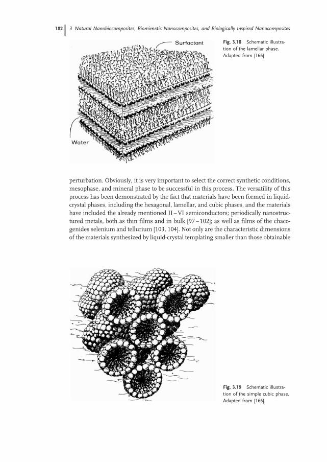
perturbation. Obviously, it is very important to select the correct synthetic conditions,mesophase, and mineral phase to be successful in this process. The versatility of thisprocess has been demonstrated by the fact that materials have been formed in liquid-crystal phases, including the hexagonal, lamellar, and cubic phases, and the materialshave included the already mentioned II–VI semiconductors; periodically nanostruc-tured metals, both as thin films and in bulk [97–102]; as well as films of the chaco-genides selenium and tellurium [103, 104]. Not only are the characteristic dimensionsof the materials synthesized by liquid-crystal templating smaller than those obtainable
Fig. 3.18 Schematic illustra-
tion of the lamellar phase.
Adapted from [166]
Fig. 3.19 Schematic illustra-
tion of the simple cubic phase.
Adapted from [166].
3 Natural Nanobiocomposites, Biomimetic Nanocomposites, and Biologically Inspired Nanocomposites182

by lithographic techniques, but they are often attainable through bulk synthesis, whichis obviously not possible via lithography.The direct templating of materials in the preordered environment of a nonionic
amphiphilic mesophase generates semiconductor/organic superlattices containingboth the symmetry and the long-range order of the precursor liquid crystal. In thetemplated growth of II–VI semiconductors, the semiconductor is grown in awater-containing liquid crystal by reaction of H2S or H2Se with a dissolved saltsuch as Cd(NO3)2. Both the chemical nature and the structure of the amphiphileare important for direct templating. For example, the order obtained in the nanostruc-tured systems was even observed to be dependent on the counterion for the metal [95].One advantage of direct templating with liquid crystals as a route to nanostructure
formation, as was already discussed, is that there are a large number of amphiphilicliquid crystals, with lattice constants ranging from a few nanometers to tens of nan-ometers, and which include lamellar, hexagonal, cubic, and bicontinuous phases [84,105, 106]. Potentially, many of these systems can be mineralized, generating materialswith an array of novel structures and properties.Specifically, II–VI semiconductors have been directly templated by hexagonal liquid
crystals based on (EO) 10 oleyl [11, 93, 95], and a lamellar liquid crystal formed fromoligo(vinyl alcohol) (23) oleyl ester [93]. As expected, the hexagonal liquid crystal
Fig. 3.20 The structure on the left in the transmission electron micrograph (bottom) is
nanostructured CdS viewed with the hexagonally packed cylindrical templated pores
parallel to the electron beam; the one on the right has the cylindrical structures per-
pendicular to the electron beam. Top: model of the nanostructure as a hexagonal ar-
rangement of cylindrical pores of low electron density, corresponding to organic material
in a solid matrix of semiconductor. The left and right schematic representations corre-
spond to the adjacent micrographs; the central view shows the cylindrical assemblies in an
intermediate state of rotation
3.4 Biologically Inspired Nanocomposites 183183

yielded product with a hexagonal nanostructure, and the lamellar liquid crystal yieldeda lamellar structure. (EO) 10 oleyl can also form a lamellar liquid crystal, which also wassuccessful in templating a lamellar CdS product. Other lyotropic phases, such as avariety of bicontinuous and cubic liquid crystals [84, 105, 107], may also yield inter-esting mineral nanostructures. In this regard, CdS has been grown in a body-centeredcubic phase by using a triblock copolymer of poly(oxyethylene)-poly(oxypropylene)-poly(oxyethylene) [(EO) 106 (PO) 70 (EO) 106] as the amphiphile. When mixed withwater, the PO segment is only weakly solvated, but the EO is highly solvated.Thus, when this molecule is hydrated it forms micelles which pack closely, forminga cubic phase [106]. The result of precipitation in this cubic phase was the formation ofhollow nanospheres of CdS, which are covered later in this chapter.It is remarkable that a soft organic liquid crystal can directly template a hard covalent
mineral phase. As a specific example, a hexagonal mesophase consisting of 50 vol. %aqueous 0.1 M Cd(OAc)2 and 50 vol. % (EO) 10 oleyl templated an inorganic/organicnanocomposite of CdS and amphiphile when exposed to H2S gas (Figure 3.20) [93].The composite material contained an internal nanostructure that replicated the sym-metry and dimensions of the liquid crystal in which it was grown. Interestingly, CdSand ZnS exhibited a superlattice morphology when formed in a liquid crystal fromtheir respective nitrate salts and H2S, but Ag2S, CuS, HgS, and PbS did not (Figure3.21). CdSe is also nanostructured by this method (Figure 3.22). An additional virtue ofthe (EO) 10 oleyl system is that, when combined with H2O, it forms a hexagonal me-sophase at 25 8C over the range of 35 to 65 vol. % amphiphile and a lamellar me-
Fig. 3.21 Transmission electron micrographs of mineralized structures grown in hexagonal mesophases
from their respective nitrate salt and H2S (bar = 50 nm, except for PbS where the bar is 250 nm)
3 Natural Nanobiocomposites, Biomimetic Nanocomposites, and Biologically Inspired Nanocomposites184
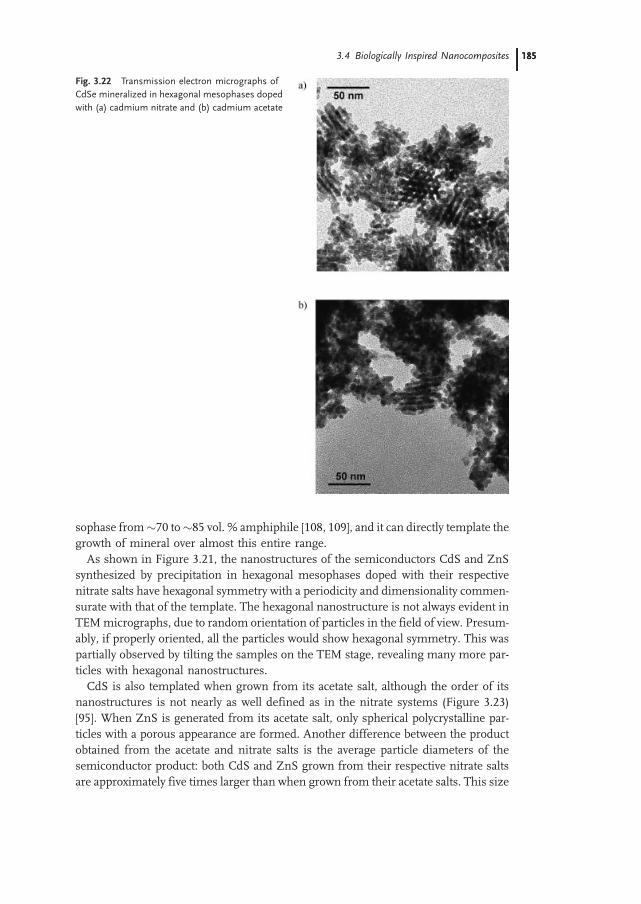
sophase from70 to85 vol. % amphiphile [108, 109], and it can directly template thegrowth of mineral over almost this entire range.As shown in Figure 3.21, the nanostructures of the semiconductors CdS and ZnS
synthesized by precipitation in hexagonal mesophases doped with their respectivenitrate salts have hexagonal symmetry with a periodicity and dimensionality commen-surate with that of the template. The hexagonal nanostructure is not always evident inTEMmicrographs, due to random orientation of particles in the field of view. Presum-ably, if properly oriented, all the particles would show hexagonal symmetry. This waspartially observed by tilting the samples on the TEM stage, revealing many more par-ticles with hexagonal nanostructures.CdS is also templated when grown from its acetate salt, although the order of its
nanostructures is not nearly as well defined as in the nitrate systems (Figure 3.23)[95]. When ZnS is generated from its acetate salt, only spherical polycrystalline par-ticles with a porous appearance are formed. Another difference between the productobtained from the acetate and nitrate salts is the average particle diameters of thesemiconductor product: both CdS and ZnS grown from their respective nitrate saltsare approximately five times larger than when grown from their acetate salts. This size
Fig. 3.22 Transmission electron micrographs of
CdSe mineralized in hexagonal mesophases doped
with (a) cadmium nitrate and (b) cadmium acetate
3.4 Biologically Inspired Nanocomposites 185185

difference can be clearly observed in low magnification electron micrographs. As con-trols, CdS was also grown in aqueous environments from both the nitrate and acetateprecursors, and as expected, no nanostructure was generated. The counterion of themetal did not affect the templating of the other mineral systems studied: Ag2S, CuS,HgS, and PbS were not generated with a superlattice morphology when grown in ahexagonal mesophase, irrespective of whether the acetate or nitrate salts were used.The reason may be that the byproduct of the synthesis from the nitrate salt is nitricacid, whereas the byproduct of the synthesis from the acetate salt is acetic acid. Nitricacid is a much stronger acid, and apparently enables the mineral phase to reformaround the template during growth so as to remove any structural defects.As already mentioned, in addition to the hexagonal mesophase, a lamellar meso-
phase of (EO) 10 oleyl also can template a precipitated mineral (Figure 3.24). The la-
Fig. 3.23 Transmission electron micrographs of CdS grown in identical hexagonal mesophases except for
precursor salt. Note the significantly improved order when cadmium nitrate is used as the precursor over the
order obtained with cadmium acetate
Fig. 3.24 Schematic representation of the lamellar organic template and transmission
electron micrograph of the resulting product after mineralization. The dark bands are CdS
that mineralized in the hydrophilic region of the template liquid crystal; mineral growth is
prohibited in the hydrophobic regions
3 Natural Nanobiocomposites, Biomimetic Nanocomposites, and Biologically Inspired Nanocomposites186

mellar periodicity in the resulting CdS is 7 nm, which agrees very well with theperiodicity of the lamellar template. The lamellar morphology can be confirmed bycareful tilting of particles within the TEM. If a particle is tilted about an axis perpen-dicular to the stripes, no change is observed in the pattern. However, if it is tilted on anaxis parallel to the stripes (and perpendicular to the electron beam), the pattern quicklydisappears. These observations constitute strong evidence for a lamellar morphologywithin the particles and agree closely with results obtained from lamellar nanocom-posites formed in a poly(vinyl alcohol)-based liquid crystal [94]. As shown in Figure3.24, themineralized product consists of disk-like particles with a long axis in the planeof the layers that is 1.5 times the maximum width perpendicular to the layers. Veryinterestingly, particles having lamellar morphology do not disperse, even with re-peated ultrasonication, perhaps due to mineral or organic bridging between theCdS layers. Presumably, CdS nucleates within a hydrophilic layer of the mesophaseand grows rapidly in the plane, but concurrently an occasional finger forms perpen-dicular to this layer, piercing the hydrophobic region. This finger then nucleates an-other layer of CdS, resulting in a mineral bridge between layers. Another possibility istethering of organic molecules in the mineral phase, tying the layers together. Ofcourse, growth in the plane of the layers is faster than growth perpendicular to thelayers, generating the disk-like habit observed. Not surprisingly, since it seems to en-hance the templating effect, lamellar-nanostructured CdS was seen only when thenitrate salt was used, while the acetate salt afforded only small particles.The layered structure formed by templating with a lamellar liquid crystal is in fact
reminiscent of the layered abalone shell structure; however, in the templated materialthe characteristic dimension is just a few nanometers, not hundreds of nanometers tomicrometers. It still remains to be seen if the properties of the layered material aresignificantly improved over those of the solid equivalent, but if the abalone shell is anyguide, advanced mechanical properties are a possibility.As described, mineral growth in the hexagonal and lamellar phases yields interest-
ing, controlled nanostructures. Mineral growth in the cubic phase formed from (EO)
106 (PO) 70 (EO) 106 was also done, using cadmium acetate andH2S as precursors [110].Although the mechanism is not entirely understood, the result was hollow spheres20–200 nm in diameter (Figure 3.25), which can be observed by both TEM andSEM. When the sample is tilted in the stage, the shape and observed structure donot change, as expected for a hollow sphere (Figure 3.26). If the particles had beencorpuscular in shape, their appearance would change as a function of sample tilt.The strongest evidence for their hollow nature is the dark edges of the spheres ob-served in TEM micrographs. If each sphere were solid, TEM would show greater scat-tering from the center than the edges, making the center appear darker. In the SEM,the spheres also scatter the most electrons from their edges and appear somewhattransparent in their centers, providing further proof of their hollow nature (Figure3.25). Unlike materials produced by direct templating in hexagonal and lamellar li-quid crystals, the hollow spheres are not of a size commensurate with the structureof the liquid crystal, but are rather 1–10 times the size of the characteristic dimensionof the liquid crystal in which they were formed.
3.4 Biologically Inspired Nanocomposites 187187

Because the characteristic dimension (diameter) for hollow CdS spheres obtainedfrom the Cd(CH3CO2)2-doped cubic phase is 20–200 nm, (1–10 times the diameter ofthe micelles making up the cubic phase), it does not appear that the mineral nanos-tructure is directly templated by the liquid crystal. In addition, this nanostructure isentirely absent from the CdS when the cubic phase is doped with Cd(NO3)2 as theprecursor salt. This result is important when taken in the context of previous resultsin which the use of the nitrate salt led to a nanostructure with enhanced order [95]. Inessence, the nitrate salt allowed the growing mineral to access a thermodynamicallylower-energy morphology, which was a nanostructure commensurate with the struc-ture of the liquid crystalline matrix. The inability of the nitrate salt to ‘sharpen’ theorder in the cubic system is not surprising, because, as observed in previous stu-dies, the nitrate salt only improves the registry between the nanostructure and theliquid crystal and does not result in a new nanostructure. In the cubic system, thespheres are not a copy of the liquid crystal, so there is no registry to improve. Themineralization of the cubic phase must lead to local rearrangements of the liquidcrystal, leading to the hollow-sphere morphology observed; however, the detailed me-chanism is still not understood.
Fig. 3.25 Scanning electron micrograph of hollow
spheres of CdS mineralized within a cubic meso-
phase
Fig. 3.26 Transmission electron microscope tilt
series of hollow CdS spheres grown in an acetate-
doped cubic phase. The tilt axis was diagonal run-
ning from upper left to lower right of each micro-
graph. (a) –458, (b) 08, (c) 458
3 Natural Nanobiocomposites, Biomimetic Nanocomposites, and Biologically Inspired Nanocomposites188

A potentially significant difference between the cubic phase and the other phasesstudied (hexagonal and lamellar) is the connectivity of the hydrophilic and hydropho-bic portions of the liquid crystal. In the lamellar and hexagonal phases, both theseregions are continuous in at least one direction. In the cubic phase, however, the hy-drophobic regions are confined to discrete micelles. This confinement may cause adifference in templating ability relative to the other phases. For all templatingphases, as the mineral nucleates and grows, it is necessary to expel some moleculesfrom the volume occupied by themineral. For both the lamellar and hexagonal phases,a molecule can diffuse away from the growing mineral without ever exposing its hy-drophobic (oleyl) or hydrophilic (EO) segments to domains of the opposite nature. Incontrast, in the cubic phase, when a molecule is forced away from the growingmineralit must leave its micelle and expose its hydrophobic (PO) segment to the polar sur-roundings (EO + H2O), a high-energy situation. As already stated, the nitrate salt al-lows the mineral phase to access a lower-energy configuration, which in the lamellarand hexagonal systems results in a high degree of fidelity between the template and thesemiconductor nanostructure. That a hollow-spheremorphology is not observed in thecubic system when the nitrate salt is used is not surprising, given that the hollowmorphology is not directly templated by the liquid crystal and that formation ofthe spheres requires the mesophase to go through a high-energy intermediatestate. The full reason for the spherical morphology when Cd(CH3CO2)2 is used asthe semiconductor precursor must be due to a subtle kinetic balance that is notyet understood. At the very least, the energy difference between the lamellar, hexago-nal, and cubic systems is rather small, and thus the fact that templating is successful inthe first two systems but unsuccessful in the last indicates that some fairly specificinteractions are necessary for direct templating. This is similar to the action ofmany biological systems, in which very specific interactions between proteins andother macromolecules and growing inorganic phases are exceedingly important forstructural development.In addition to simple one-component systems, it is interesting to consider the result
of templating binary mixtures of the precursor salts within a liquid crystal. In onesystem, a hexagonal mesophase containing 0.05 M Cd(NO3)2 and 0.05 M Zn(NO3)2was mineralized. The resulting semiconductor (CdxZn1-xS; x 0.5) product’s nanos-
Fig. 3.27 Transmission electron micrograph of the product
obtained from precipitation in a hexagonal mesophase
doped with 0.05 M Cd(NO3)2 and 0.05 M Zn(NO3)2. The
templated product is a solid solution of CdS and ZnS
3.4 Biologically Inspired Nanocomposites 189189

tructure exactly matched that of the template (Figure 3.27). In a system of 0.05 MPb(NO3)2 and 0.05 M Zn(NO3)2, the result was a very different nanostructure, whichconsisted of a single-crystal core of PbS surrounded by a shell of nanostructured ZnS(Figure 3.28). From this it appears that, when mixed metal products are synthesized,there is a direct correspondence between the behavior of the constituent solids and themixed solid. CdxZn1-xS was nanostructured (as were CdS and ZnS, Figure 3.21), butprecipitation from Pb2+ and Zn2+ ions resulted in a single crystal of PbS surrounded bynanostructured polycrystalline ZnS, corresponding with the result seen for PbS andZnS when grown discretely (Figure 3.21). The formation of mixed metal precipitatesgives an insight into the growth processes and also opens the possibility of engineeringa property. The system of CdxZn1-xS offers the possibility of band-gap engineering,although, due to the somewhat lower solubility of CdS than ZnS in water, the particlesmay be cadmium-rich in their center and zinc-rich on their exterior. The differingsolubilities of PbS and ZnS in water play a very important role in the structure ofthe particles formed from this mixed system. PbS has a much lower solubilitythan ZnS and, as a result, upon exposure of the doped mesophase to H2S, single-crys-tal PbS cubes nucleate and grow. Then, after most of the Pb2+ ions are locally ex-hausted, ZnS heterogeneously nucleates on the PbS particles. As expected, becauseZnS is templated by liquid crystals, the shell of ZnS around the PbS single crystalcontains a periodic superlattice structure.Direct templating of an inorganic by an organic liquid crystal may depend on many
factors, the most important of which is probably the thermodynamic stability of themesophase throughout the mineral growth process. The mesophase must be stable tothe addition of mineral precursors, and the mineral precipitation process must notdisrupt the order of the liquid crystal. In studying direct templating, researchershave observed that the textures observed by polarized optical microscopy are thesame for the pure mesophase and for a mesophase that contains the precursorsalt, indicating that the doping did not lead to radical disruption of the order inthe mesophase. Nuclear magnetic resonance (NMR) can also be utilized to verifythe structure of liquid crystalline mesophases. To verify that the characteristic mole-
Fig. 3.28 Transmission electron micrograph of a
composite product of PbS and ZnS grown in a
hexagonal mesophase doped with 0.05 M
Pb(NO3)2 and 0.05 M Zn(NO3)2. The single crystal
cube at the core of the particle is PbS, and the shell
is a periodically nanostructured solid consisting of
ZnS
3 Natural Nanobiocomposites, Biomimetic Nanocomposites, and Biologically Inspired Nanocomposites190

cular order of the mesophase was not disrupted by ion doping, broadline 2H NMRspectra were obtained from both cadmium ion-doped and undoped mesophases[96]. For both mesophases, the same quadrupole splitting was observed (Figure3.29). If ionic doping had perturbed the structure of the mesophase, the splittingwould have decreased [111, 112]. As additional proof of molecular order in the me-sophase, x-ray diffractograms were collected to characterize both the mesophase’slong period and symmetry. For systems containing 35%, 40%, 50%, and 60% am-phiphile, the 100, 110, and 200 reflections are clearly observed, indicating that theliquid crystalline structure is hexagonal (Figure 3.30). A mesophase containing78% amphiphile forms a lamellar liquid crystal, as indicated by the presence of100 and 200 reflections and the absence of a 110 reflection (Figure 3.31). As ex-pected, a strong correlation was found between the phase diagrams as determinedby optical analyses and the x-ray data. Similar experiments have been performed
Fig. 3.29 Quadrupole splitting for a hexagonal mesophase (a) doped with 0.1
M cadmium acetate and (b) undoped. The splitting indicated by an arrow is the
same for both samples
3.4 Biologically Inspired Nanocomposites 191191
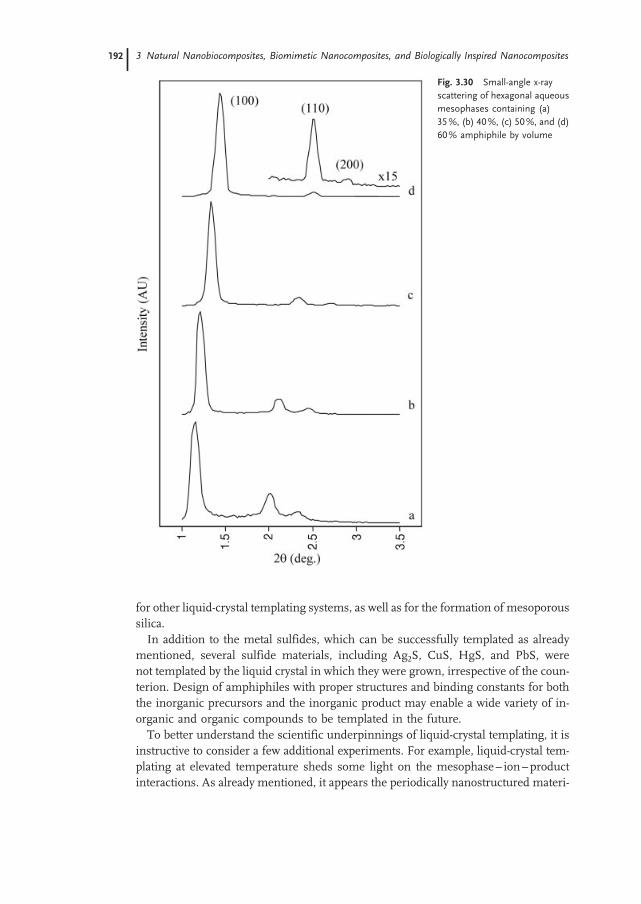
for other liquid-crystal templating systems, as well as for the formation of mesoporoussilica.In addition to the metal sulfides, which can be successfully templated as already
mentioned, several sulfide materials, including Ag2S, CuS, HgS, and PbS, werenot templated by the liquid crystal in which they were grown, irrespective of the coun-terion. Design of amphiphiles with proper structures and binding constants for boththe inorganic precursors and the inorganic product may enable a wide variety of in-organic and organic compounds to be templated in the future.To better understand the scientific underpinnings of liquid-crystal templating, it is
instructive to consider a few additional experiments. For example, liquid-crystal tem-plating at elevated temperature sheds some light on the mesophase– ion–productinteractions. As already mentioned, it appears the periodically nanostructured materi-
Fig. 3.30 Small-angle x-ray
scattering of hexagonal aqueous
mesophases containing (a)
35%, (b) 40%, (c) 50%, and (d)
60% amphiphile by volume
3 Natural Nanobiocomposites, Biomimetic Nanocomposites, and Biologically Inspired Nanocomposites192

als are thermodynamically stable with respect to their solid equivalent. This impliesthat there is a critical energy balance between the energy gained by reducing the sur-face area of the mineral phase and the energy lost due to disruption of the mesophasestructure. To study this further, CdS was precipitated in mesophases at both 35 8C and50 8C. These temperatures are both below the isotropization temperature of the dopedmesophases, so the reactions were carried out in a self-assembled medium. The CdSproduced from the reaction at 35 8C did express the order of the mesophase, albeitpoorly when compared with the order obtained at room temperature (22 8C). Precipi-tation at 50 8C resulted in mineral with no periodic order, clearly indicating that theenergetic difference between periodically nanostructured and disordered product issmall and that it only takes a small perturbation to result in nonnanostructured pro-duct.As additional evidence for the direct templating mechanism, samples composed of
35%, 40%, 50%, and 60% by weight (EO) 10 oleyl were mineralized with CdS. Byvarying the amphiphile content of the mesophase, the spacing between the cylindricalaggregates of amphiphilic molecules making up the hexagonal mesophase was varied.Assuming that CdS is directly templated by the liquid crystal in which it is grown, thehexagonal symmetry and associated length scale should be nearly identical to thatfound in the precursor hexagonal mesophase, which is what indeed happened.The result (Figure 3.32), demonstrating that the superlattice dimension in the preci-pitate can be varied by changing the lattice constant of the mesophase, is very strongevidence for direct templating. If the nanostructure present in the templated inorganicphase had been the result of a cooperative self-assembly process, much as occurs for
Fig. 3.31 Small-angle x-ray scattering of a lamellar mesophase containing
78% amphiphile and 22% water by volume
3.4 Biologically Inspired Nanocomposites 193193

most mesoporous silica systems, the result would have been that the periodicity of thenanostructure would not have changed with varying water content.
3.4.2
Liquid-Crystal Templating of Thin Films
The templating of thin films by self-organized organic structures should find signifi-cant application in both technology and scientific study. Thin-film templating is struc-turally related to the bulk templating of inorganic materials, which generally results inperiodically structured particles; however, because the result is a periodically struc-tured thin film, the potential for application is clearer. Templating with organic struc-tures is especially intriguing because of the potential to create features much smallerthan those feasible by almost any top-down technique, because it utilizes the nanoscalemolecular order inherent in self-assembled organic structures to define the structureof the resulting thin film. A few key points must hold true for successful thin-filmtemplating by liquid crystals. First, clearly, for templating to be successful, the self-assembled matrix must be compatible with the substrate. Then, via some process,the inorganic material must be deposited or grown on the substrate. Realistically,only chemical and electrochemical routes for materials deposition can meet these
Fig. 3.32 Center-to-center spacing in a cylindrical assembly of amphiphilic
molecules of hexagonal mesophases as determined by x-ray diffraction (*), and
center-to-center pore spacing in templated CdS as measured by transmission
electron microscopy (^). Both are plotted as a function of the water content in
the mesophase
3 Natural Nanobiocomposites, Biomimetic Nanocomposites, and Biologically Inspired Nanocomposites194

requirements. Other conventional methods of thin-film deposition require high va-cuum, which is incompatible with lyotropic liquid crystals and furthermore cannotoperate through a thick overlying layer of liquid crystal.The synthetic routes for liquid-crystal templating of thin films are relatively straight-
forward. To date, most studies have used electrochemical techniques to drive the ma-terial deposition. First, a precursor containing lyotropic liquid crystal is interfaced withthe substrate. Then, under an applied potential, material is electrochemically depos-ited at the liquid-crystal/substrate interface. Nanostructured materials that have beencreated through this process include a variety of metals, selenium, and tellurium [97,99–104, 113]. It may also be possible to electrodeposit other interesting materialsincluding semiconductors; however, no publications have yet appeared demonstrat-ing success.Throughout, it is quite interesting that all the successful templating experiments
have relied on liquid crystals formed of nonionic amphiphiles. However, in biol-ogy, most preformed matrices are formed via ionic macromolecules. In part, thisis likely because biology makes use of very specific interactions to create mineral struc-tures, but synthetic systems do not have this degree of sophistication. Thus, the factthat nonionic amphiphiles are much more stable to varying concentrations of solublesalts is actually an advantage. Ionic amphiphiles (as well as biomolecules) are affectedmuch more strongly by salts, because a single salt ion can bind to one or more of thepolar amphiphile headgroups, greatly reducing their polarity. This was indeed ob-served for several of the anionic amphiphiles studied, and most likely was the reasonthat ionic systems were not successful in templating the growth of a mineral phase. Inbiology, where the molecular structures are designed to interact specifically with onesalt under very specific conditions, the strong interaction of ionic groups with dis-solved species is an advantage. However, for generalized synthetic systems, thismay not be an advantage.
3.4.3
Block-Copolymer Templating
Block copolymers are a widely studied class of materials that organize into both 2D and3D structures at slightly longer length scales than observed for liquid crystals. Similarphase behavior is observed, with systems transitioning between lamellar, hexagonaland cubic phases as the relative volume fraction of the two blocks changes [87]. Muchmore complex morphologies can form in triblock systems. The characteristic periodi-city in block copolymer systems ranges from 5 nm to hundreds of nanometers andprimarily depends on the molecular weight of the block copolymer. As expected, as themolecular weight of the block copolymer increases, the characteristic length scale in-creases. It was realized that if there was a way to impart this nanoscale order into asubstrate, one might have a powerful technique for patterning materials with a per-iodic array of nanometer-sized structures. Unlike lyotropic liquid crystals, block copo-lymers are generally solvent-free and can be taken to elevated temperatures and undervacuum without destabilizing the self-assembled structure; thus high-vacuum mate-
3.4 Biologically Inspired Nanocomposites 195195
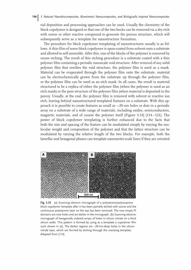
rial deposition and processing approaches can be used. Usually the chemistry of theblock copolymer is designed so that one of the two bocks can be removed via a dry etchwith ozone or other reactive compound to generate the porous structure, which willsubsequently serve as a template for nanostructure formation.The procedure for block copolymer templating of nanostructures usually is as fol-
lows. A thin film of some block copolymer is spun-coated from solvent onto a substrateand allowed to self-assemble. After this, one of the blocks of the polymer is removed byozone etching. The result of this etching procedure is a substrate coated with a thinpolymer film containing a periodic nanoscale void structure. After removal of any solidpolymer film that overlies the void structure, the polymer film is used as a mask.Material can be evaporated through the polymer film onto the substrate, materialcan be electrochemically grown from the substrate up through the polymer film,or the polymer film can be used as an etch mask. In all cases, the result is materialstructured to be a replica of either the polymer film (when the polymer is used as anetch mask) or the pore structure of the polymer film (whenmaterial is deposited in thepores). Usually, at the end, the polymer film is removed with solvent or reactive ionetch, leaving behind nanostructured templated features on a substrate. With this ap-proach it is possible to create features as small as 20 nm holes or dots in a periodicarray on a substrate of a wide range of materials, including oxides, semiconductors,magnetic materials, and of course the polymer itself (Figure 3.33) [114–121]. Thepower of block copolymer templating is further enhanced due to the facts thatboth the size and spacing of the feature can be modulated simply by varying the mo-lecular weight and composition of the polymer and that the lattice structure can bemodulated by varying the relative length of the two blocks. For example, both thelamellar and hexagonal phases can template nanometer-scale lines if they are oriented
Fig. 3.33 (a) Scanning electron micrograph of a polystyrene/polyisoprene
block copolymer template after it has been partially etched with ozone and the
continuous polystyrene layer on the top has been removed. The now empty PI
domains are now holes and are darker in the micrograph. (b) Scanning electron
micrograph of hexagonally ordered arrays of holes in silicon nitride on a thick
silicon wafer. This pattern is formed by using as a template a copolymer film
such shown in (a). The darker regions are ~20-nm-deep holes in the silicon
nitride layer, which are formed by etching through the overlying template.
Adapted from [114]
3 Natural Nanobiocomposites, Biomimetic Nanocomposites, and Biologically Inspired Nanocomposites196
properly on the substrate. I should point out that the periodic arrays of dots have at-tracted the greatest attention for applications such as magnetic storage media.
3.4.4
Colloidal Templating
In any discussion of biologically inspired nanocomposite materials, one must includerecent developments on colloidal crystal templating of photonic materials. The basicpremise behind this approach is to use the 3D periodic structure of synthetic opals todirect the structure of a second phase material. This approach is not biologically in-spired, but should more accurately be described as ‘naturally inspired’, because opals,although natural, are geological, not biological, in origin. Furthermore, although thelower limit to the characteristic length scale of thematerial generated is 10–20 nm, thecharacteristic dimension is often relatively large, on the order of 500 nm. This is in factintentional, since most of the applications for these materials are optical, and thus thecharacteristic length should not be much smaller than the wavelength of the light thatone desires to modulate. Commonly, however, much smaller features are embeddedwithin the templated structure, and these features may be as small as a few nan-ometers. Because of the clear natural inspiration for the colloidal templating of ma-terials and the relationship of the templating process to many biological processes, Icover this approach in this chapter.The interest in microperiodic 3D structures has grown tremendously due to the
exciting potential of such materials, particularly in the area of photonics [122].Such 3D structures, often termed photonic crystals, are the extension of the well-known dielectric stack into three dimensions. Although the colors that occur inopals, which stem from diffraction of white light by planes of highly ordered submic-rometer silica spheres, are our inspiration; for practical application, synthetic ap-proaches are needed to create materials and structures with the necessary refractiveindex and periodicity to meet the requirements for most optical applications, whichopals simply do not have.A particularly interesting class of optical structures are the so-called photonic band-
gapmaterials. For example, a microperiodicmaterial consisting of low-refractive-indexspheres arranged in a face-centered-cubic array in a matrix with a high index of re-fraction, and having a lattice constant on the order of the wavelength of light (visibleor infrared), could be such a photonic band-gap material [123]. Similar to how a di-electric stack has a stop-band for light in a given frequency range, this material wouldnot allow light in a given frequency range to travel through it in any direction. In es-sence, it would be an omnidirectional, perfectly lossless, mirror.The synthesis of these structures however is exceedingly difficult. Layer-by-layer
fabrication of photonic crystals using state-of-the-art VLSI tools, e.g., deep UV photo-lithography, chemical vapor deposition (CVD), chemical-mechanical polishing, hasbeen demonstrated [3], but formidable processing difficulties limit the formationof large area and truly 3D structures.When appropriately formed, self-assembled colloidal crystals are natural candidates
for the construction of photonic crystals. Good crystal quality is achieved only with
3.4 Biologically Inspired Nanocomposites 197197
colloids that have very low size polydispersity (<5%), which currently limits the choiceof materials to SiO2 or polymers, both of which have a fairly low index of refractionaround 1.5, which is much smaller than that required for most optical applications.This has led researchers to take a two-stage templating approach. In a first step thedesired microperiodic structure is assembled by using colloids. In a second step thisstructure is used as a template to build a complementary structure with a materialhaving a higher index of refraction [124].Colloidal crystal templating is a very promising approach for production of high-
resolution, micrometer-scale, 3D periodic photonic crystals, but as conventionally ap-plied to the fabrication of photonic band gap structures it has serious optical limita-tions, unless materials with the necessary optical properties can be used. Typically, themost important point is to infill with a material with a sufficiently high refractive indexto generate an optically interesting material. A range of approaches have been sug-gested to maximize the index contrast, including sol–gel [125–127], chemical vapordeposition [128–131], imbibing of nanoparticles [132–134], reduction of GeO2 to Ge[135], electroless [136] and electrochemical deposition [137], and melt imbibing [138].In addition, polymers have been used to infill colloidal crystals, and in one report, thecolloidal particles were less than 100 nm in diameter, which, although perhaps notinteresting from an optical standpoint, may have potential for separation membranesand confined chemical reactor spaces [139]. Although they are not the focus of thefollowing discussion, the colloidal templates used in these attempts are commonlypolycrystalline and can contain unacceptably high numbers of defects; thus, substan-tial effort has also gone into creating colloidal crystals with low defect densities. Each ofthese infilling techniques has various advantages and disadvantages, which are dis-cussed below. In general, they all consist of approaches to infill the interstitial spaceof the colloidal template, after which the colloidal template is generally removed.The sol–gel infilling of colloidal crystal templates is intriguing to consider as a route
to 3D porous materials [125–127], although it is somewhat limited in application forphotonic materials for several reasons. First, the refractive index of most materials thatcan be formed via sol–gel is < 2 (with the exception of TiO2, which can have a re-fractive index of 2.5), second, there is considerable reduction in volume duringthe conversion of the sol to solid material, and third, the refractive index of mostsol–gel-derived material is substantially less than that of a single crystal of thesame material. The net effect is that most sol–gel-derived macroporous materialshave relatively low refractive index contrast, and their long-range order is somewhatdisrupted due to the uneven contraction of thematrix. However, if one is not interestedin photonic materials, but rather is attempting to make a ceramic macroporous ma-terial, sol–gel infilling of colloidal crystals may be a very good route. The contraction ofthe matrix may in fact be an advantage, in that it may be possible to make structureswith pore diameters on the order of 50% of the diameter of the template. Because it isdifficult to make colloidal crystal templates from spheres smaller than a few hundrednanometers, this may be valuable for creating nanoperiodic structures.Another pathway to macroporous materials is to fill the interstitial space of a col-
loidal crystal with nanoparticles, followed by removal of the colloidal template. Thishas some advantages over sol–gel infilling, in that the contraction of the structure
3 Natural Nanobiocomposites, Biomimetic Nanocomposites, and Biologically Inspired Nanocomposites198

upon removal of the template from a nanoparticle filled colloidal crystal is significantlyless than that seen upon removal of the template from a sol-gel filled system, and amuch larger subset of materials can be prepared as nanoparticles, including semicon-ductors, metals, and ceramics. The first example of semiconductor nanoparticle in-filling of colloidal template used II–VI semiconductor nanoparticles [132]; sincethen, Er-doped TiO2 nanoparticles, for example, have been filled into a colloidal tem-plate, followed by removal of the template to generate a macroporous solid (Figure3.34) [140].The use of CVD as a pathway to filling colloidal crystals at first may seem counter-
intuitive. After all, CVD generally is most efficient at coating planar surfaces, and itwould seem almost impossible to fill structures with deep pores, such as the interstitialspace of a 3D colloidal crystal. However, significant strides have been made in the pastfew years, and now virtually complete infilling of colloidal structures with both Si andGe via CVD has been demonstrated [128–131]. After dissolution of the colloidal tem-plate, the result is an inverse structure with the necessary refractive index and struc-tural conditions to exhibit a complete photonic band gap.Electrodeposition-based infilling is intriguing for several reasons and has the poten-
tial to be general with respect to both characteristic lattice constant and material (Fig-ure 3.35). The potential for high-refractive-index materials, large area structures, andthe complete infilling of thick 3D colloidal templates, as well as the low cost of elec-trodeposition have led to interest in this area. To date, three different classes of ma-terials that have been electrodeposited into self-assembled colloidal crystals, namelysemiconductors, polymers, and metals.Semiconductors are interesting candidates for photonic crystals, primarily because
of their high refractive indices and generally robust nature. For example, CdS has arefractive index of 2.5, and materials such as GaP, Si, and Ge have indices of 3.4, 3.5,and 4.0, respectively. However, routes to creating periodic macroporous structures
Fig. 3.34 Left, transmission electron micrographs
of 3% erbium-doped hydrothermally synthesized
titania nanoparticles. Right, scanning electron mi-
crographs of macroporous titania structure formed
by imbibing these nanoparticles into a colloidal
template formed from 466 nm polystyrene colloidal
particles. The colloidal template was removed by
calcination at 300 8C for one hour in air
3.4 Biologically Inspired Nanocomposites 199199

Fig. 3.35 Generalized procedure for creating 3D
periodic macroporous materials by colloidal tem-
plating and electrodeposition. Monodisperse col-
loids sediment onto a conducting substrate, self-
assembling into a crystal. The sample may be dried
and sintered before electrolyte is added. A coun-
terelectrode allows electrodeposition of the desired
material (semiconductor, polymer, metal) into the
interstitial spaces. In a final step the electrolyte and
the templating colloid are removed. For polymeric
colloids this can be done by treatment at elevated
temperature or by dissolution with a solvent. For
silica colloids, aqueous HF is effective for dissol-
ving the template
3 Natural Nanobiocomposites, Biomimetic Nanocomposites, and Biologically Inspired Nanocomposites200

Fig. 3.36 Schematic representation of the ex-
perimental setup for potentiostatic deposition of
CdSe through the interstitial space of a colloidal
crystal
Fig. 3.37 Scanning electron micrographs of po-
tentiostatically deposited CdSe (a) and galvanos-
tatically deposited CdS (b, c) after removal of the
polystyrene colloidal template. In the overdeposited
system (b), the overlying solid CdS film can be
clearly seen on the right. The apparent lack of
periodic pore structure in the underdeposited
system is not due to disorder in the colloid, but
occurs because the nodular surface of the semi-
conductor cuts through multiple lattice planes of
the template
3.4 Biologically Inspired Nanocomposites 201201

from such materials are limited because of their very high melting points and lowsolubility in common solvents.To date, the II–VI semiconductors CdS and CdSe [137, 141], and ZnO [142], have
been electrochemically grown through colloidal templates, resulting, after dissolutionof the template, in macroporous semiconductor films. For all systems, a conductingoxide film on glass was used as the substrate. Macroporous CdS films were generatedby galvanostatic deposition through the interstitial spaces of a colloidal crystal formedfrom 1 lm SiO2 spheres, and CdS and CdSe macroporous films were generated bypotentiostatic deposition through a colloidal template generated from 466 nmpolystyr-ene spheres (Figure 3.36). After electrodeposition, the SiO2 and polystyrene colloidaltemplates were removed with aqueous HF and toluene, respectively. Because of thehigh rigidity of the semiconductor network, contraction upon removal of the templatewas limited to a few percent at most. The fine and gross morphologies of the electro-deposited semiconductors are shown in Figure 3.37.Macroporous ZnO films were formed by potentiostatic deposition through a colloi-
dal crystal formed from 368 nm polystyrene spheres, and the spheres were removedwith toluene. Careful control of the electrodeposition conditions was necessary: ifelectrodeposition was done at a potential less negative than –1.0 V vs. Ag/AgCl, largecrystalline grains of ZnO formed, which disrupted the structure of the colloidal tem-plate. Using a deposition potential more negative than –1.0 V suppressed the forma-tion of large-grain ZnO, and the colloidal template was not disrupted.All the electrodeposited semiconductor films are reported to be opalescent; however,
detailed optical spectroscopy has yet to be performed. Real progress in optically inter-esting materials may await the electrochemical deposition of materials such as GaP,Ge, and Si, which, because they have refractive indices >3, may result in materialswith 3D photonic band gaps. Routes to the electrodeposition of such materialshave been demonstrated [143], but problems, such as hydrogen gas evolution andgenerally harsh conditions, need to be solved before success in these areas is likely.Electrodeposition of conducting polymers (electropolymerization) through self-as-
sembled colloidal crystals, followed by removal of the colloidal template, is a promisingroute to achieving active macroporous materials. Several significant advancementsover the past few years have begun to demonstrate the potential of conducting poly-mer-basedmicroperiodic photonic structures. Inherently, because of the low refractiveindex of polymeric materials, it is quite unlikely that a 3D photonic band-gap materialwill result from a polymer-based photonic crystal; however, conducting polymers haveadvantageous properties as compared to conventional polymers or inorganic materi-als: their optical properties can be electrochemically modulated, fine control over prop-erties can be obtained through organic chemistry, and they are often mechanicallyflexible.Electrochemical growth of conducting polymers is a fairly well developed field, and
many procedures for growing solid films have been published [144]. There are, how-ever, only a few reports on the growth of porous conducting polymer films. Fibers ofpolypyrrole, poly(3-methylthiophene), and polyaniline were formed in the early 1990sby electrodeposition from the appropriate monomer solution through a porous mem-brane [145]. The first example of electrochemical deposition of a conducting polymer
3 Natural Nanobiocomposites, Biomimetic Nanocomposites, and Biologically Inspired Nanocomposites202

around a colloidal template was in 1992, when polypyrrole was grown around latexparticles [146]. However, no attempt was made to remove the colloidal particles,and the optical properties of the resulting films were not measured. Only in thepast few years have researchers been exploring the possibility of the templated growthof conducting polymers for photonic applications.To date, three reports on colloidal templating of conducting polymers have ap-
peared, all of which followed the general procedure of (1) colloidal crystal formationon a conducting substrate, (2) electrochemical deposition from solution, and (3) dis-solution of the colloidal template with an appropriate solvent. In the first example,polypyrrole was grown potentiostatically from a solution of pyrrole in acetonitrilethrough a colloidal crystal composed of SiO2 spheres with a mean diameter of238 nm assembled on F-doped SnO2-coated glass, followed by removal of the colloidaltemplate with aqueous HF [147]. Macroporous polypyrrole, polyaniline, and poly-bithiophene films have been potentiostatically polymerized through a colloidal crystalassembled from 500 nm and 750 nm polystyrene spheres, on a substrate of gold-coated glass. The polystyrene template was then removed with toluene [148]. Inthe most recent example, polypyrrole and polythiophene macroporous films were po-tentiostatically grown through colloidal crystals assembled from 150 nm and 925 nmpolystyrene spheres, respectively, on glass coated with indium tin oxide; the polystyr-ene was removed with tetrahydrofuran [149]. A preliminary optical characterization[149] showed a weak dip in transmittance that appeared to be correlated with the per-iodic structure.One significant issue is the contraction of the period structure upon removal of
solvent for electrodeposited macroporous polymers. This was most clearly observedin polystyrene-templated systems, in which significant contraction, ranging from13% to 40%, was observed for the macroporous polypyrrole and polyaniline. How-ever, very little contraction was observed in polystyrene-templated macroporous poly-bithiophene or when SiO2 spheres were used as the template. For example,poly(ethylenedioxythiophene) was templated by silica colloidal particles (Figure3.38). The primary difference is that organic solvents are used to remove the polystyr-ene spheres and an aqueous HF solution is used to remove the SiO2 spheres. Thissuggests that the organic solvent softens the electrodeposited polymer, allowing itto contract; however, there may be other systems similar to polybithiophene, in whichcontraction of the macroporous matrix does not occur. This is less of a problem formacroporous metals and semiconductors.Metallic macroporous ordered replicas of colloidal assemblies are of potential inter-
est for a wide range of applications including filtration, separation, and catalysis. Inaddition, they might have interesting electrical, magnetic, or optical properties. Thetools and techniques for electrochemically plating metals have been well establishedfor thin films and even bulk materials. It is thus fairly straightforward to develop re-cipes to backfill the interstitial space of a colloidal self-assembled crystal with almostany metal.From a photonic standpoint, the properties of bulk metals are very poor, although of
course templated structures may have many other applications. The imaginary com-ponents of the dielectric constants of bulk metals are large, hence they readily absorb
3.4 Biologically Inspired Nanocomposites 203203

light. When the metallic structures become small enough, however, strong opticalresonances associated with plasmon frequencies of the conduction electron in themetals can lead to qualitatively new phenomena. A well-known example of this isthe red color of a nanosized dispersion of gold colloid. A more recent manifestationof unexpected behavior is the anomalously high light transmission through smallholes (<200 nm) in thin metallic films [150].Theoretical calculations [151–153] on ordered 3Darrays ofmetallo-dielectric spheres
show that these are promising for the construction ofmaterials with full photonic band-gap in the visible part of the optical spectrum. The advantage of metallo-dielectricstructures over purely dielectric structures is that it should be easier to achieve afull band-gap in the visible. A full band-gap in the visible is exceedingly difficult, ifnot impossible, to create with purely dielectric structures, because very few dielectricmaterialshaveanindexofrefraction>3andverylowabsorptioninthevisible.Thishasledto the development of synthesis routes to producemetallo-dielectric colloidal core-shellparticleswith sizes in the submicrometer range [154, 155] andmetallic shell thicknessesor cores that are small enough to show resonance effects.Vos et al. [156] made gold replicas of colloidal crystals made of silica (radius 113 nm)
and polystyrene (radius 322 nm). Prior to electrodeposition of the gold, the silicaspheres were sintered by heat treatment at 600 8C. After electrodeposition of thegold, the silica template was removed by etching with aqueous HF, and the polystyr-ene spheres were removed by combustion at 450 8C (Figure 3.39). There are no dimen-sional changes between the dried, sintered colloid and the final replica, although somecracking is observed during the original drying and sintering process, indicating thatthe electrochemically formed gold is dense and structurally robust. This is a definiteimprovement over other methods of infilling macroporous structures with high-di-electric materials, e.g., liquid-phase or sol–gel chemistry [126, 127], and infiltration
Fig. 3.38 Scanning electron micrograph of poly(ethylenedioxythiophene)
electrodeposited around a colloidal crystal template, after dissolution of the
template
3 Natural Nanobiocomposites, Biomimetic Nanocomposites, and Biologically Inspired Nanocomposites204
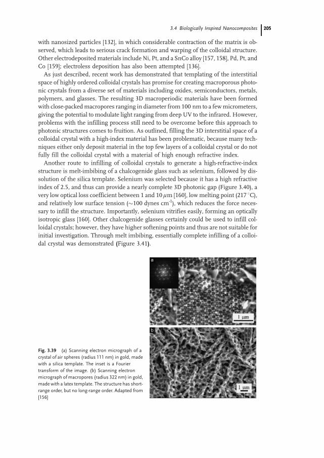
with nanosized particles [132], in which considerable contraction of the matrix is ob-served, which leads to serious crack formation and warping of the colloidal structure.Other electrodepositedmaterials include Ni, Pt, and a SnCo alloy [157, 158], Pd, Pt, andCo [159]; electroless deposition has also been attempted [136].As just described, recent work has demonstrated that templating of the interstitial
space of highly ordered colloidal crystals has promise for creating macroporous photo-nic crystals from a diverse set of materials including oxides, semiconductors, metals,polymers, and glasses. The resulting 3D macroperiodic materials have been formedwith close-packedmacropores ranging in diameter from 100 nm to a fewmicrometers,giving the potential to modulate light ranging from deep UV to the infrared. However,problems with the infilling process still need to be overcome before this approach tophotonic structures comes to fruition. As outlined, filling the 3D interstitial space of acolloidal crystal with a high-index material has been problematic, because many tech-niques either only deposit material in the top few layers of a colloidal crystal or do notfully fill the colloidal crystal with a material of high enough refractive index.Another route to infilling of colloidal crystals to generate a high-refractive-index
structure is melt-imbibing of a chalcogenide glass such as selenium, followed by dis-solution of the silica template. Selenium was selected because it has a high refractiveindex of 2.5, and thus can provide a nearly complete 3D photonic gap (Figure 3.40), avery low optical loss coefficient between 1 and 10 lm [160], low melting point (217 8C),and relatively low surface tension (100 dynes cm-1), which reduces the force neces-sary to infill the structure. Importantly, selenium vitrifies easily, forming an opticallyisotropic glass [160]. Other chalcogenide glasses certainly could be used to infill col-loidal crystals; however, they have higher softening points and thus are not suitable forinitial investigation. Through melt imbibing, essentially complete infilling of a colloi-dal crystal was demonstrated (Figure 3.41).
Fig. 3.39 (a) Scanning electron micrograph of a
crystal of air spheres (radius 111 nm) in gold, made
with a silica template. The inset is a Fourier
transform of the image. (b) Scanning electron
micrograph of macropores (radius 322 nm) in gold,
made with a latex template. The structure has short-
range order, but no long-range order. Adapted from
[156]
3.4 Biologically Inspired Nanocomposites 205205
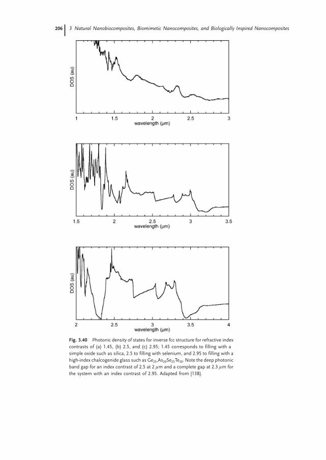
Fig. 3.40 Photonic density of states for inverse fcc structure for refractive index
contrasts of (a) 1.45, (b) 2.5, and (c) 2.95; 1.45 corresponds to filling with a
simple oxide such as silica, 2.5 to filling with selenium, and 2.95 to filling with a
high-index chalcogenide glass such as Ge25,As20Se25Te30. Note the deep photonic
band gap for an index contrast of 2.5 at 2 lm and a complete gap at 2.3 lm for
the system with an index contrast of 2.95. Adapted from [138].
3 Natural Nanobiocomposites, Biomimetic Nanocomposites, and Biologically Inspired Nanocomposites206

Infilling was accomplished by imbibing molten selenium under high pressure intothe colloidal crystal, followed by quenching to vitrify the selenium. Subsequently, thecolloidal crystal template was removed withHF, resulting in amacroporous selenium/air structure with a high contrast in refractive index.
3.5
Summary
The confluence of nanoscience, biotechnology, and materials chemistry offers greatpotential for discovery and fabrication of advanced composite materials. Greatamounts of information still need to be gleaned from the study of biological sys-tems, but we have now reached a point where the current body of knowledge on
Fig. 3.41 Scanning electron micrographs of a
selenium photonic crystal cut and polished to ex-
pose specific crystallographic faces. (a) Polished
(001) facet, which is perpendicular to the settling
direction. The contact points between the spheres
on adjacent layers are clearly visible as pores, but
within the (001) plane the voids do not appear to be
interconnected. This pore morphology is the result
of a 2% mismatch between the sphere diameter
and the template size. (b) (110) face, proof that the
selenium photonic crystal is indeed fcc. Again, the
voids are generally not interconnected within the
(001) plane, but are interconnected between (001)
planes. (c) Low-magnification scanning electron
micrograph of the (110) face, presenting a cross
section of the entire thickness of the selenium
photonic crystal. The sample was mounted in epoxy
prior to polishing, which is seen below the photonic
crystal; solid selenium is present above the
photonic crystal. Importantly, the structure is highly
ordered throughout the entire crystal, including the
top layer. Because of an ~1.58misorientation of the
polished sample with respect to the (110) face, the
size of the pores appears to change from left to
right across the sample. Adapted from [138]
3.5 Summary 207207
how biological systems can create highly functional nanocomposites is starting to en-able the creation of advanced materials. For example, natural systems widely exploitself-assembly to create a great diversity of interesting and highly functional materials,and today we are beginning to also create synthetic systems by similar processes. Wemust always remember that biological organisms work with a limited subset of ma-terials and take up to years to create nanocomposite structures, so, rather than attempt-ing to create materials by direct mimicking of biology, it will likely be much moreproductive to create materials by exploiting the design rules expressed by biologicalsystems and applying them to synthetic systems. The dividends for research into bio-logically inspired nanocompositematerials are great, andmuch progress is expected inthe near future.
References
1 Corma A: From microporous to mesopo-rous molecular sieve materials and theiruse in catalysis. Chem. Rev. 1997,97:2373–2419.
2 Brinker CJ: Oriented inorganic films. Curr.Opin. Colloid Interface Sci. 1998, 3:166–173.
3 Soten I, Ozin GA: New directions in self-assembly: materials synthesis over ‘all’length scales. Curr. Opin. Colloid InterfaceSci. 1999, 4:325–337.
4 Antonietti M: Surfactants for novel tem-plating applications. Curr. Opin. ColloidInterface Sci. 2001, 6:244–248.
5 Sayari A,Hamoudi S: Periodicmesoporoussilica-based organic: inorganic nanocom-posite materials. Chem. Mater. 2001,13:3151–3168.
6 Stroscio JA, Eigler DM: Science 1991,254:1319–1326.
7 Whitesides GM, Mathias JP, Seto CT:Molecular self-assembly and nanochemi-stry: a chemical strategy for the synthesis ofnanostructures. Science 1991, 254:1312–1319.
8 Mann S, Ozin GA: Synthesis of inorganicmaterials with complex form. Nature 1996,382:313–318.
9 Nanostructures: Special Issue: Nanostruc-tured Materials. Chem. Mater. 1996,8:1569–1882.
10 Stupp SI, LeBonheur V, Walker K, Li LS,Huggins KE, Keser M, Amstutz A: Su-pramolecular Materials: Self-organizednanostructures. Science 1997, 276:384–389.
11 Stupp SI, Braun PV: Molecular manipula-tion of microstructures: biomaterials, ce-ramics, and semiconductors. Science 1997,277:1242–1248.
12 Liu J, Kim AY, Wang LQ, Palmer BJ, ChenYL, Bruinsma P, Bunker BC, Exarhos GJ,Graff GL, Rieke PC, et al.: Self-assembly inthe synthesis of ceramic materials andcomposites. Adv. Colloid Interface Sci.1996, 69:131.
13 Shenton W, Pum D, Sleytr UB, Mann S:Synthesis of cadmium sulfide superlatticesusing self-assembled bacterial S-layers.Nature 1997, 389:585–587.
14 Neeraj, Rao CNR: Metal chalcogenide-or-ganic nanostructured composites fromself-assembled organic amine templates. J.Mater. Chem. 1998, 8:279–280.
15 Schnur JM: Lipid Tubules: A paradigm formolecularly engineered structures. Science1993, 262:1669–1676.
16 Archibald DD, Mann S: Template mine-ralization of self-assembled anisotropic li-pid microstructures. Nature 1993, 364:430.
17 Kresge CT, Leonowicz ME, Roth WJ, Var-tuli JC, Beck JS: Ordered mesoporpousmolecular sieves synthesized by a liquid-crystal template mechanism. Nature 1992,359:710–712.
18 Beck JS, Vartuli JC, Kennedy GJ, KresgeCT, Roth WJ, Schramm SE: Chem. Mater.1994, 6:1816–1821.
19 Monnier A, Schuth F, Huo Q, Kumar D,Margolese D, Maxwell RS, Stucky GD,Krishnamurty M, Petroff P, Firouzi A, etal.: Cooperative formation of inorganic-or-
3 Natural Nanobiocomposites, Biomimetic Nanocomposites, and Biologically Inspired Nanocomposites208

ganic interfaces in the synthesis of silicatemesostructures. Science 1993, 261:1299–1303.
20 Huo Q, Margolese DI, Ciesla U, Feng P,Gier TE, Sieger P, Leon R, Petroff PM,Schuth F, Stucky GD: Generalized syn-thesis of periodic surfactant/inorganiccomposite materials. Nature 1994,368:317–321.
21 Firouzi A, Kumar D, Bull LM, Besier T,Sieger P, Huo Q, Walker SA, ZasadzinskiJA, Glinka C, Nicol J, et al.: Cooperativeorganization of inorganic-surfactant andbiomimetic assemblies. Science 1995,267:1138–1143.
22 Attard GS, Glyde JC, Goltner CR: Nature1995, 378:366–368.
23 Beck JS, Vartuli JC: Curr. Opin. Solid StateMater. Sci. 1996, 1:76.
24 Hinman MB, Jones JA, Lewis RV: TrendsBiotechnol. 2000, 18:374.
25 Hayashi CY, Shipley NH, Lewis RV: Int. J.Biol. Macromol. 1999, 24:271.
26 Gosline JM, Guerette PA, Ortlepp CS, Sa-vage KN: J. Exp. Biol. 1999, 202:3294.
27 Hayashi CY, Lewis RV: Science 2000, 387.28 Thiel BL, Viney C, Jelinski LW: b sheets
and spider silk. Science 1996, 273:1477–1480.
29 Simmons AH, Michal CA, Jelinski LW:Molecular orientation and two-componentnature of the crystalline fraction of spiderdragline silk. Science 1996, 271:84–87.
30 Lazaris A, Arcidiacono S, Huang Y, Zhou J-F, Duguay F, Chretien N,Welsh EA, SoaresJW, Karatzas CN: Spider silk fibers spunfrom soluble recombinant silk produced inmammalian cells. Science 2002, 295:472–476.
31 Harrison CC: Evidence for intramineralmacromolecules containing protein fromplant silicas. Phytochem. 1996, 41:37–41.
32 Mann S: Biomineralization: Principles andConcepts in Bioinorganic Materials Che-mistry. Oxford: Oxford University Press;2002.
33 Schultze-Lam S, Harauz G, Beveridge TJ:Participation of a cyanobacterial S layer infine-grain mineral formation. J. Bacteriol.1992, 174:7971–7981.
34 Schultze-Lam S, Fortin D, Davis BS, Be-veridge TJ: Mineralization of bacterialsurfaces. Chem. Geol. 1996, 132:171–181.
35 Weiner S, Addadi L: Design strategies inmineralized biological materials. J. Mater.Chem. 1997, 7:689–702.
36 Weiner S, Traub W, Wagner HD: Lamellarbone: structure– function relations. J.Struct. Biol. 1999, 126:241–255.
37 Weiner S, Wagner HD: The material bone:structure mechanical function relations.Annu. Rev. Mater. Sci. 1998, 28:271–298.
38 Douglas K, Clark NA, Rothschild KJ: Na-nometer molecular lithography. Appl.Phys. Lett. 1986, 48:676–678.
39 Douglas K, Clark NA, Rothschild KJ: Bio-molecular/solid-state nanoheterostructu-res. Appl. Phys. Lett. 1990, 56:692–694.
40 Coffer JL, Bigham SR, Li X, Pinizzotto RF,Rho YG, Pirtle RM, Pirtle IL: Dictation ofthe shape of mesoscale semiconductornanoparticle assemblies by plasmid DNA.Appl. Phys. Lett. 1996, 69:3851–3853.
41 Mirkin CA, Letsinger RL, Mucic RC,Storhoff JJ: A DNA-based method for ra-tionally assembling nanoparticles intomacroscopic materials. Nature 1996,382:607–609.
42 Alivisatos AP, Johnsson KP, Peng XG,Wilson TE, Loweth CJ, Jr, Bruchez MP,Schultz PG: Organization of ‘nanocrystalmolecules’ using DNA. Nature 1996,382:609–611.
43 Alivisatos AP, Schultz PG, Peng XG, Lo-weth CJ, Caldwell WB: DNA-based as-sembly of gold nanocrystals. Angew.Chem., Int. Ed. Engl. 1999, 38:1808–1812.
44 Soto CM, Srinivasan A, Ratna BR: Con-trolled assembly of mesoscale structuresusing DNA as molecular bridges. J. Am.Chem. Soc. 2002, 124:8508–8509.
45 Brown S: Engineered iron oxide-adhesionmutants of the Escherichia coli phage-lambda receptor. Proc. Natl. Acad. Sci.U.S.A. 1992, 89:8651–8655.
46 Brown S: Metal recognition by repeatingpolypeptides. Nat. Biotechnol. 1997,15:269–272.
47 Whaley SR, English DS, Hu EL, BarbaraPF, Belcher AM: Selection of peptides withsemiconductor binding specificity for di-rected nanocrystal assembly. Nature 2000,405:665–668.
48 Lee SW, Mao CB, Flynn CE, Belcher AM:Ordering of quantum dots using geneti-
3.5 Summary 209209

cally engineered viruses. Science 2002,296:892–895.
49 Addadi L, Weiner S: Control and designprinciples in biological mineralization.Angew. Chem., Int. Ed. Engl. 1992,31:153–169.
50 Weller H: Colloidal semiconductor Q-par-ticles: chemistry in the transition regionbetween solid state and molecules. Angew.Chem., Int. Ed. Engl. 1993, 32:41–53.
51 Weller H: Quantized semiconductor par-ticles: a novel state of matter for materialsscience. Adv. Mater. 1993, 5:88–95.
52 Weller H: Optical properties of quantizedsemiconductor particles. Philos. Trans. R.Soc. London, Ser. A 1996, 354:757–766.
53 Murray CB, Norris DJ, Bawendi MG: J.Am. Chem. Soc. 1993, 115:8706.
54 Dabbousi BO, Murray CB, Rubner MF,Bawendi MG: Langmuir–Blodgett mani-pulation of size-selected cdse nanocrystal-lites. Chem. Mater. 1994, 6:216–219.
55 Murray CB, Kagan CR, Bawendi MG: Self-organization of CdSe nanocrystallites intothree-dimensional quantum dot superlat-tices. Science 1995, 270:1335–1338.
56 Alivisatos AP: Semiconductor nanocry-stals. MRS Bull. 1995, 20:23–32.
57 Peng X, Wilson TE, Alivisatos AP, SchultzPG: Synthesis and isolation of a homodi-mer of cadmium selenide nanocrystals.Angew. Chem., Int. Ed. Engl. 1997,36:145–147.
58 Brus LE: Electron–electron and electron–hole interactions in small semiconductorcrystallites: the size dependence of the lo-west excited electronic state. J. Chem. Phys.1994, 80:4403–4409.
59 Siegel RW: Creating nanophase materials.Sci. Am. 1996, 275(December):74–79.
60 Fendler JH, Meldrum FC: The colloidchemical approach to nanostructured ma-terials. Adv. Mater. 1995, 7:607–632.
61 Geppert L: Semiconductor lithography forthe next millennium, IEEE Spectrum 1996,33: 33–38.
62 Levenson MD: Solid State Technol. 1995(Sept) 81.
63 Chang THP, Thomson MGR, Yu ML,Kratschmer E, Kim HS, Lee KY, RishtonSA, Zolgharnain S: Microelectron. Eng.1996, 32:113.
64 Matsui S, Ochiai Y: Nanotechnology 1996,7:247.
65 Smith HI, Schattenburg ML, Hector SD,Ferrera J, Moon EE, Yang IY, Bukhardt M:Microelectron. Eng. 1996, 32:143.
66 Marrian CRK, Snow ES: Microelectron.Eng. 1996, 32:173.
67 Zhao X-M, Xia Y, Whitesides GM: J. Mater.Chem 1997, 7:1069.
68 Fendler JH: Membrane-Mimetic Approachto Advanced Materials. Berlin: Springer-Verlag; 1994.
69 Peng XG, Manna L, Yang WD, Wickham J,Scher E, Kadavanich A, Alivisatos AP:Shape control of CdSe nanocrystals. Nature2000, 404:59–61.
70 Manna L, Scher EC, Alivisatos AP: Syn-thesis of soluble and processable rod-, ar-row-, teardrop-, and tetrapod-shaped CdSenanocrystals. J. Am. Chem. Soc. 2000,122:12700–12706.
71 Berman A, Addadi L, Weiner S: Nature1988, 331:546–548.
72 Berman A, Addadi L, Kvick A, LeiserowitzL, Nelson M, Weiner S: Science 1990,250:664–667.
73 Berman A, Hanson J, Leiserowitz L,Koetzle TF, Weiner S, Addadi L: Science1993, 259:776–779.
74 Messersmith PB, Stupp SI: High-tempe-rature chemical and microstructuraltransformations of a nanocomposite orga-noceramic. Chem. Mater. 1995, 7:454–460.
75 Mitzi DB, Feild CA, Harrison WTA, GuloyAM: Conducting tin halides with a layeredorganic-based perovskite structure. Nature1994, 369:467–469.
76 Mitzi DB, Wang S, Feild CA, Chess CA,Guloy AM: Conducting layered organic-inorganic halides containing <110>-oriented perovskite sheets. Science 1995,267:1473–1476.
77 Feng X, Fryxell GE,WangQ-L, KimAY, LiuJ, Kemner KM: Functionalized monolayerson ordered mesoporous supports. Science1997, 276:923–926.
78 Weiss D, Roukes ML, Mensching A,Grambow P, Klitzing Kv, Weimann G:Electron pinball and commensurate orbitsin a periodic array of scatters. Phys. Rev.Lett. 1991, 66:2790–2793.
3 Natural Nanobiocomposites, Biomimetic Nanocomposites, and Biologically Inspired Nanocomposites210

79 Hansen W, Kotthaus JP, Merkt U: Elec-trons in Laterally Periodic Nanostructures,vol. 35. Ed. Hansen W, Kotthaus JP, MerktU. San Diego:Academic Press; 1992:279–380.
80 Schechter RS, Bourrel M (Ed): Microe-mulsions and Related Systems: Formation,Solvency, and Physical Properties. NewYork: Marcel Dekker; 1988.
81 Tanford C: J. Phys. Chem. 1974, 78:2469.82 Rosoff M (Ed): Vesicles. New York: Marcel
Dekker; 1996.83 Ringsdorf H, Schlarb B, Venzmer J: An-
gew. Chem., Int. Ed. Engl. 1988, 27:114–158.
84 Laughlin RG: The Aqueous Phase Behaviorof Surfactants. San Diego: Academic Press;1994.
85 Degiorgio V, Corti M (Ed): Physics ofAmphiphiles: Micelles, Vesicles and Mi-croemulsions. Amsterdam: Elsevier Sci-ence Pub. Co.; 1985.
86 Israelachvili J: Thermodynamic and geo-metrical aspects of amphiphile aggregationinto micelles, vesicles, and bilayers, and theinteractions between them. In Physics ofAmphiphiles: Micelles, Vesicles and Mi-croemulsions. Ed. Degiorgio V, Corti M;1985:24.
87 Bates FS: Polymer–polymer phase beha-vior. Science 1991, 251:898–905.
88 Wennerstrom H: J. Colloid Interface Sci.1979, 68:589–590.
89 Tiddy G: Phys. Rep. 1980, 57:1.90 Fribreg SE, Wang J: J. Dispersion Sci.
Technol. 1991, 12:387–402.91 Walsh D, Hopwood JD, Mann S: Crystal
tectonics: constructruction of reticulatedcalcium phosphate frameworks in bicon-tinuous reverse microemulsions. Science1994, 264:1576–1578.
92 Yang JP, Qadri SB, Ratna BR: Structuraland morphological characterization of pbsnanocrystallites synthesized in the bicon-tinuous cubic phase of a lipid. J. Phys.Chem. 1996, 100:17255–17259.
93 Braun PV, Osenar P, Stupp SI: Semicon-ducting superlattices templated by mole-cular assemblies. Nature 1996, 380:325–328.
94 Osenar P, Braun PV, Stupp SI: Adv. Mater.1996, 8:1022.
95 Tohver V, Braun PV, Pralle MU, Stupp SI:Counterion effects in liquid crystal tem-plating of nanostructured CdS. Chem.Mater. 1997, 9:1495–1499.
96 Braun PV, Osenar P, Tohver V, KennedySB, Stupp SI: Nanostructure templating ininorganic solids with organic lyotropic li-quid crystals. J. Am. Chem. Soc. 1999,121:7302–7309.
97 Attard GS, Bartlett PN, Coleman NRB,Elliott JM, Owen JR,Wang JH:Mesoporousplatinum films from lyotropic liquid cry-stalline phases. Science 1997, 278:838–840.
98 Attard GS, EdgarM, Goltner CG: Inorganicnanostructures from lyotropic liquid crystalphases. Acta Materialia 1998, 46:751–758.
99 Elliott JM, Birkin PR, Bartlett PN, AttardGS: Platinum microelectrodes with uniquehigh surface areas. Langmuir 1999,15:7411–7415.
100 Attard GS, Leclerc SAA, Maniguet S,Russell AE, Nandhakumar I, Bartlett PN:Mesoporous Pt/Ru alloy from the hexago-nal lyotropic liquid crystalline phase of anonionic surfactant. Chem. Mater. 2001,13:1444.
101 Attard GS, Leclerc SAA, Maniguet S,Russell AE, Nandhakumar I, Gollas BR,Bartlett PN: Liquid crystal phase templatedmesoporous platinum alloy. MicroporousMesoporous Mater. 2001, 44:159–163.
102 Nelson PA, Elliott JM, Attard GS, Owen JR:Mesoporous nickel/nickel oxide: a na-noarchitectured electrode. Chem. Mater.2002, 14:524–529.
103 Nandhakumar I, Elliott JM, Attard GS:Electrodeposition of nanostructured me-soporous selenium films (H-I-eSe). Chem.Mater. 2001, 13:3840.
104 Gabriel T, Nandhakumar IS, Attard GS:Electrochemical synthesis of nanostructu-red tellurium films. Electrochem. Com-mun. 2002, 4:610–612.
105 Schick MJ: Nonionic Surfactants, PhysicalChemistry. New York: Marcel Dekker;1987.
106 Wanka G, HoffmannH, Ulbricht W: Phasediagrams and aggregation behavior ofpoly(oxyethylene)-poly(oxypropylene)-poly(oxyethylene) triblock copolymers inaqueous solutions. Macromolecules 1994,27:4145–4159.
3.5 Summary 211211

107 Fontell K: Cubic phases in surfactant andsurfactant-like lipid systems. Colloid Po-lym. Sci. 1990, 268:264–285.
108 Lo I, Florence AT, Treguier J-P, Seiller M,Puisieux F: The influence of surfactantHLB and the nature of the oil phase on thephase diagrams of nonionic surfactant-oil-water systems. J. Colloid Interface Sci.1977, 59:319–327.
109 Treguier JP, Seiller M, Puisieux F, Orec-chioni AM, Florence AT: Effect of a hy-drophilic surfactant and temperature onwater-surfactant-oil diagrams. In FirstExpo. Cong. Int. Technol. Pharm. 1977:Assoc. Pharm.; 1977:75–87.
110 Braun PV, Stupp SI: CdS mineralization ofhexagonal, lamellar, and cubic lyotropicliquid crystals. Mater. Res. Bull. 1999,34:463–469.
111 Blackburn JC, Kilpatrick PK: Using deute-rium NMR line shapes to analyze lyotropicliquid crystalline phase transitions. Lang-muir 1992, 8:1679–1687.
112 Schnepp W, Disch S, Schmidt C: 2H NMRstudy on the lyomesophases of the systemhexaethylene glycol dodecyl methyl ether/water: temperature dependence of qua-drupole splittings. Liq. Cryst. 1993,14:843–852.
113 Attard GS, Goltner CG, Corker JM, HenkeS, Templer RH: Liquid-crystal templatesfor nanostructured metals. Angew. Chem.,Int. Ed. Engl. 1997, 36:1315–1317.
114 Park M, Harrison C, Chaikin PM, RegisterRA, Adamson DH: Block copolymer li-thography: periodic arrays of 1011 holesin one square centimeter. Science 1997,276:1401–1404.
115 Park M, Chaikin PM, Register RA,Adamson DH: Large area dense nanoscalepatterning of arbitrary surfaces. Appl. Phys.Lett. 2001, 79:257–259.
116 Li RR, Dapkus PD, Thompson ME, JeongWG,Harrison C, Chaikin PM, Register RA,Adamson DH: Dense arrays of orderedGaAs nanostructures by selective areagrowth on substrates patterned by blockcopolymer lithography. Appl. Phys. Lett.2000, 76:1689–1691.
117 Thurn-Albrecht T, Schotter J, Kastle CA,Emley N, Shibauchi T, Krusin-Elbaum L,Guarini K, Black CT, Tuominen MT,Russell TP: Ultrahigh-density nanowire
arrays grown in self-assembled diblockcopolymer templates. Science 2000,290:2126–2129.
118 Kim HC, Jia XQ, Stafford CM, Kim DH,McCarthy TJ, Tuominen M, Hawker CJ,Russell TP: A route to nanoscopic SiO2posts via block copolymer templates. Adv.Mater. 2001, 13:795.
119 Lin ZQ, Kim DH, Wu XD, Boosahda L,Stone D, LaRose L, Russell TP: A rapidroute to arrays of nanostructures in thinfilms. Adv. Mater. 2002, 14:1373–1376.
120 Bal M, Ursache A, Touminen MT, Gold-bach JT, Russell TP: Nanofabrication ofintegratedmagnetoelectronic devices usingpatterned self-assembled copolymer tem-plates. Appl. Phys. Lett. 2002, 81:3479–3481.
121 Shin K, Leach KA, Goldbach JT, Kim DH,Jho JY, Tuominen M, Hawker CJ, RussellTP: A simple route to metal nanodots andnanoporous metal films. Nano Lett. 2002,2:933–936.
122 Joannopoulos JD, Meade RD, Winn JN:Photonic Crystals: Molding the Flow ofLight. Princeton: Princeton UniversityPress; 1995.
123 Busch K, John S: Photonic band gap for-mation in certain self-organizing systems.Phys. Rev. E 1998, 58:3896–3908.
124 Velev OD, Kaler EW: Structured porousmaterials via colloidal crystal templating:from inorganic oxides to metals. Adv.Mater. 2000, 12:531–534.
125 Velev OD, Jede TA, Lobo RF, Lenhoff AM:Porous silica via colloidal crystallization.Nature 1997, 389:447–448.
126 Holland BT, Blanford CF, Stein A: Syn-thesis ofmacroporousminerals with highlyordered three-dimensional arrays of sphe-rical voids. Science 1998, 281:538–540.
127 Wijnhoven JEGJ, Vos WL: Preparation ofphotonic crystals made of air spheres intitania. Science 1998, 281:802–804.
128 Zakhidov AA, Baughman RH, Iqbal Z, CuiCX, Khayrullin I, Dantas SO, Marti I,Ralchenko VG: Carbon structures withthree-dimensional periodicity at opticalwavelengths. Science 1998, 282:897–901.
129 Mguez H, Blanco A, Meseguer F, Lopez C,Yates HM, Pemble ME, Fornes V, MifsudA: Brag diffraction from indium phosphide
3 Natural Nanobiocomposites, Biomimetic Nanocomposites, and Biologically Inspired Nanocomposites212

infilled fcc silica colloidal crystals. Phys.Rev. B 1999, 59:1563–1566.
130 Blanco A, Chomski E, Grabtchak S, IbisateM, John S, Leonard SW, Lopez C, Mese-guer F, Miguez H, Mondia JP, et al.: Large-scale synthesis of a silicon photonic crystalwith a complete three-dimensional band-gap near 1.5 micrometers. Nature 2000,405:437–440.
131 Vlasov YA, Bo XZ, Sturm JC, Norris DJ:On-chip natural assembly of silicon pho-tonic bandgap crystals. Nature 2001,414:289–293.
132 Vlasov YA, Yao N, Norris DJ: Synthesis ofphotonic crystals for optical wavelengthsfrom semiconductor quantum dots. Adv.Mater. 1999, 11:165–169.
133 Subramania G, Constant K, Biswas R, Si-galas MM, Ho K-M: Optical photonic cry-stals fabricated from colloidal systems.Appl. Phys. Lett 1999, 74:3933–3935.
134 Subramanian G, Manoharan VN, ThorneJD, Pine DJ: Ordered macroporous mate-rials by colloidal assembly: a possible routeto photonic bandgap materials. Adv. Mater.1999, 11:1261–1265.
135 Mguez H, Meseguer F, Lopez C, HolgadoM, Andreasen G, Mifsud A, Fornes V:GermaniumFCC structure from a colloidalcrystal template. Langmuir 2000, 16:4405–4408.
136 Jiang P, Cizeron J, Bertone JF, Colvin VL:Preparation of macroporous metal filmsfrom colloidal crystals. J. Am. Chem. Soc.1999, 121:7957–7958.
137 Braun PV, Wiltzius P: Electrochemicallygrown photonic crystals. Nature 1999,402:603–604.
138 Braun PV, Zehner RW, White CA, WeldonMK, Kloc C, Patel SS, Wiltzius P: Epitaxialgrowth of high dielectric contrast three-dimensional photonic crystals. Adv. Mater.2001, 13:721–724.
139 Johnson SA, Ollivier PJ, Mallouk TE: Or-dered mesoporous polymers of tunablepore size from colloidal silica templates.Science 1999, 283:963–965.
140 Jeon S, Braun PV: Hydrothermal synthesisof Er-doped luminescent TiO2 nanopartic-les, Chem. Mater. 2003, 15: 1256–1263.
141 Braun PV, Wiltzius P: Electrochemical fa-brication of 3-D microperiodic porousmaterials. Adv. Mater. 2001, 13:482–485.
142 Sumida T, Wada Y, Kitamura T, YanagidaS: Macroporous ZnO films electrochemi-cally prepared by templating of opal films.Chem. Lett 2001, 1:38–39.
143 Pandey RK, Sahu SN, Chandra S: Hand-book of Semiconductor Electrodeposition.New York: Marcel Dekker; 1996.
144 Gurunathan K, Vadivel MA, Marimuthu R,Mulik UP, Amalnerkar DP: Electrochemi-cally synthesised conducting polymericmaterials for applications towards techno-logy in electronics, optoelectronics andenergy storage devices. Mater. Chem. Phys.1999, 61:173–191.
145 Martin CR: Nanomaterials: a membranebased synthetic approach. Science 1994,266:1961–1966.
146 Koopal CGJ, Feiters MC, Nolte RJM, De-ruiter B, Schasfoort RBM: Third generationamperometric biosensor for glucose-poly-pyrrole deposted within a matrix of uni-form latex particles as mediator. Bioelec-trochem. Bioenerg. 1992, 29:159–175.
147 Sumida T, Wada Y, Kitamura T, YanagidaS: Electrochemical preparation of macro-porous polypyrrole films with regular ar-rays of interconnected spherical voids.Chem. Commun. 2000:1613–1614.
148 Bartlett PN, Birkin PR, Ghanem MA, TohCS: Electrochemical syntheses of highlyorderedmacroporous conducting polymersgrown around self-assembled colloidaltemplates. 2001; J. Mater. Chem. 2001,11:849–853.
149 Cassagneau T, Caruso F: Semiconductingpolymer inverse opals prepared by elec-tropolymerization. Adv. Mater. 2002,14:34–38.
150 Ebbesen TW, Lezec HJ, Ghaemi HF, ThioT, Wolff PA: Extraordinary optical trans-mission through sub-wavelength hole ar-rays. Nature 1998, 391:667–669.
151 Moroz A: Three-dimensional completephotonic-band-gap structures in the visible.Phys. Rev. Lett. 1999, 83:5274–5277.
152 Moroz A: Photonic crystals of coated me-tallic spheres. Europhys. Lett. 2000,50:466–472.
153 Zhang WY, Lei XY, Wang ZL, Zheng DG,Tam WY, Chan CT, Sheng P: Robustphotonic band gap from tunable scatterers.Phys. Rev. Lett. 2000, 84:2853–2856.
3.5 Summary 213213
154 Oldenburg SJ, Averitt RD, Westcott SL,Halas NJ: Nanoengineering of optical re-sonances. Chem. Phys. Lett. 1998,288:243–247.
155 Graf C, van Blaaderen A: Metallodielectriccolloidal core-shell particles for photonicapplications. Langmuir 2002, 18:524–534.
156 Wijnhoven J, Zevenhuizen SJM, HendriksMA, Vanmaekelbergh D, Kelly JJ, Vos WL:Electrochemical assembly of ordered ma-cropores in gold. Adv. Mater. 2000,12:888–890.
157 Xu L, Zhou WL, Frommen C, BaughmanRH, Zakhidov AA, Malkinski L, Wang JQ,Wiley JB: Electrodeposited nickel and goldnanoscale meshes with potentially inter-esting photonic properties. Chem. Com-mun. 2000:997–998.
158 Luo Q, Liu Z, Li L, Xie S, Kong J, Zhao D:Creating highly ordered metal, alloy, andsemiconductor macrostructures by elec-trodeposition, ion spraying, and laserspraying. Adv. Mater. 2001, 13:286–289.
159 Bartlett PN, Birkin PR, Ghanem MA:Electrochemical deposition of macropo-rous platinum, palladium and cobalt filmsusing polystyrene latex sphere templates.Chem. Commun. 2000:1671–1672.
160 Kokorina VF: Glasses for Infrared Optics.Boca Raton, FL: CRC Press; 1996.
161 Dunin-Borkowski RE, McCartney MR,Frankel RB, Bazylinski DA, Posfai M, Bu-seck PR: Magnetic microstructure of ma-gnetotactic bacteria by electron holography.Science 1998, 282:1868–1870.
162 Zaremba CM,Morse DE,Mann S, HansmaPK, Stucky GD: Aragonite–hydroxyapatiteconversion in gastropod (abalone) nacre.Chem. Mater. 1998, 10:3813–3824.
163 Ziv V, Sabanay I, Arad T, Traub W, WeinerS: Transitional structures in lamellar bone.Microsc. Res. Technique 1996, 33:203–213.
164 Wong KKW, Douglas T, Gider S, Aw-schalom DD, Mann S: Biomimetic syn-thesis and characterization of magneticproteins (magnetoferritin). Chem. Mater.1998, 10:279–285.
165 Yang J, Meldrum FC, Fendler JH: Epitaxialgrowth of size-quantized cadmium sulfidecrystals under arachidic acid monolayers. J.Phys. Chem. 1995, 99:5500–5504.
166 Rosevear, FB: Liquid Crystals: the meso-morphic phases of surfactant compositi-ons. J. Soc. Cosmetic Chemists 1968, 19:581–594.
3 Natural Nanobiocomposites, Biomimetic Nanocomposites, and Biologically Inspired Nanocomposites214

4
Modeling of Nanocomposites
Catalin Picu and Pawel Keblinski
4.1
Introduction – The Need For Modeling
Polymer- as well as ceramic-based composites filled with nanofillers are a novel class ofmaterials. These systems are compositionally similar to conventional composites. Inboth nanocomposites and regular composites (referred to here as microcomposites),the matrix is the same. For example, polymer forming a matrix may be essentially anythermoplastic or thermosetting polymer. The feature that distinguishes the two classesof composites is the size and nature of the filler. Nanocomposites are filled with na-noparticles or with carbon nanotubes. The characteristic dimensions of the filler are<100 nm and often in the range of 100 nm. The fillers may be spheroid, such asceramic nanoparticles or carbon black; plate-like, such as layered silicates; or fiber-like, such as nanotubes.Nanocomposite materials exhibit properties that are significantly different from
those of the corresponding microcomposite. Examples are discussed at length inother chapters of this book. Polymers filled with nanoparticles have significantly en-hanced stiffness and strength compared to similar materials filled with regular micro-meter-size ceramic particles. Most importantly, a gain in these properties does notcompromise ductility, as typically occurs with conventional materials. In other sys-tems a significant ductility enhancement was measured with no decrease in strength[1, 2]. Also, ceramic nanocomposites exhibit increased fracture toughness. Other ex-amples involve fluids such as water or glycol which, when filled with metal nanopar-ticles, exhibit thermal conductivity enhancement [3] that cannot be explained by clas-sical approaches valid for standard composites [4]. This clearly indicates that, whereasa body of knowledge derived from standard continuum-level modeling approachesprovides a good description of microcomposites, it is inadequate in its currentform to describe properties and behaviors of nanocomposites.The development of these new materials, and particularly an understanding of their
properties, is still in its infancy. Consequently, to date, proofs of concept have beenrepeatedly and consistently made, but material optimization is still an elusive goal. Forexample, good filler dispersion has been demonstrated to be critical for achieving
Nanocomposite Science and Technology. Edited by P.M. Ajayan, L.S. Schadler, P.V. BraunCopyright ª 2003 WILEY-VCH Verlag GmbH Co. KGaA, WeinheimISBN: 3-527-30359-6
215215

properties superior to those of microcomposites, but it is still unclear how other para-meters such as filler distribution and filler surface functionalization influence theoverall properties. Optimization of these materials will be possible only when the phy-sics controlling the enhanced properties is properly understood, and when the proces-sing routes leading to the desired nano- and microstructures are established. The cur-rent approach to investigating these issues is experimental and based on trial anderror. Hence, modeling the material response would provide valuable informationon the underlying physics and the desired structure–property linkages. Further-more, once the desired structure is established, modeling has the capability to assistthe development of material processing.
4.2
Current Conceptual Frameworks
The properties of the matrix, the distribution and properties of the filler, and the nat-ure of their interface control the behavior of a typical microcomposite. The interfaceplays an important role in controlling several microcomposite properties such as itsthermal conductivity, load-carrying capacity, toughness, and transport properties.However, for a characteristic filler particle sizes on the micrometer scale and lar-ger, the main parameter controlling the macroscopic properties is still the filler vo-lume fraction. In these materials, the interface may be viewed in the standard way,as a 2D surface separating the constituents. By contrast, when the matrix is filledwith nanosized particles, a significant fraction of the material is either at the interfaceor within its immediate vicinity. For ceramic composites, one can argue that the inter-face width is still small relative to the filler size or the filler-to-filler distance; thusextension or modification of standard composite theory or modeling approachesmay be sufficient. For polymer nanocomposites, the modification of the matrixmay extend over several radii of gyration from the particle surface. In turn, this situa-tion results in novel macroscopic properties that are dictated qualitatively, as a trend,and quantitatively, by the behavior of the confined polymer that forms the modifiedmatrix.Several attempts have been made to provide a conceptual framework for justifying
the observed enhanced properties of polymer nanocomposites. One such theory, al-luded to above, the ‘bonded polymer layer’ [5], is based on the observation that, at thesame volume fraction, the total interfacial area in a nanocomposite is much larger thanin a microcomposite. The total volume of ‘bonded polymer’ (confined polymer next tothe filler wall) is conjectured to represent a large fraction of the volume of the nano-composite, and therefore, the properties of this confined material determine themacroscopic properties of the system. However, the available experimental resultson the existence of a bonded polymer layer are contradictory [6, 7]. It is also unclearhow thick the layer surrounding each particle is and, most importantly, what the prop-erties of the polymer in the interfacial region are.More recently, the ‘double network’ theory was proposed. This idea is based on the
observation that the reduction in particle size entails a similar reduction in the inter-
4 Modeling of Nanocomposites216

particle spacing and that special macroscopic properties are obtained when the averagedistance between particles becomes comparable to the bulk radius of gyration of thepolymer chains. These events create conditions for a chain to connect two or moreparticles, hence forming a network that provides additional strength by increasingthe number of effective entanglements in the system [8]. The intuitive appeal ofthis theory is high, but quantitative predictions that may be compared with experimen-tal results require a thorough understanding of the structure of chains confined be-tween spherical fillers.
4.3
Multiscale Modeling
Considering the multiple time and length scales characterizing nanocomposites, andpolymer nanocomposites in particular, a comprehensive approach to modeling thesesystems requires multiscale modeling. Whereas multiscale modeling across all lengthscales, from electronic level to bulk-matter sizes, and all time scales is a future chal-lenge, the various components of composites have however undergone extensive in-dependent study. The dynamics of polymers, which control the mechanical and di-electric responses of these materials, have been studied for many years. Much litera-ture exists on both molecular and continuum aspects of this problem. Several classicalmodels of stress production and chain dynamics dominate current thinking. Follow-ing an idea introduced by Guth and Mark [9], the chains are regarded as entropicsprings in tension. This concept is rooted in the observation that, as the material de-forms, the chains are stretched and their entropy decreases. The change in entropyentails a free energy variation, leading to a retractive force. The force required tostretch the chain proves proportional to the change in the end-to-end distance, whichsuggests that the chain may be compared with a linear spring. The force is alwaysretractive, and in vacuum, the chain should collapse into itself. The corollary isthat all chains are in tension. Furthermore, the force is proportional to the absolutetemperature, which is the signature of its entropic nature. The energetic component ofthe free energy is usually neglected in this theory. This view gained support from earlyexperimental observations that established unequivocally that the nature of stress inrubbers is indeed entropic.Two main models describe chain dynamics, and hence stress and dielectric relaxa-
tion. The Rouse model represents the dynamics of chains shorter than the averagedistance between entanglements, but long enough to behave as entropic springs[10]. This model is in agreement with the entropic spring description of a chain.The principal interactions accounted for are those along the chain, and the surround-ingmedium is represented in a homogenized way, bymeans of a frictional force actingon the representative chain. Chains longer than the entanglement length exhibitslower dynamics, which is described by the reptation model [11]. In this model,the effect of nonbonded interactions between monomers not directly connected bybackbone covalent bonds is conjectured to lead to constraints that force the chain
4.3 Multiscale Modeling 217217

to diffuse primarily along its contour. Several other representations have been pro-posed [12–14].A rich literature exists on the development of continuum constitutive models of
polymer behavior. These models are mostly phenomenological and are developedbased on macroscopic mechanical testing of both neat and filled polymeric materi-als. Several excellent treatises exist on this topic; [15] is a general overview.Polymer interfaces and, in particular, the polymer chain behavior close to flat inter-
faces, have been studied by simulations and have a long history of theoretical treat-ment. The study of the conformations and dynamics of linear polymeric chains in thevicinity of flat walls or free surfaces [16–29] is motivated by the many applications inwhich the behavior of confined chains is important. Such applications include, but arenot limited to, coatings, flow of molecular solutions in capillaries, and their interactionwith filters and membranes.In nanocomposites, the chain–filler interactions control to a large extent the matrix
and macroscopic properties. Therefore, understanding chain conformations and dy-namics of the confined chains next to filler surfaces is crucial. The physical picture thatemerges from the cited studies is summarized below.The conformations of a macromolecule located close to an impenetrable interface
are restricted. They are determined by the configurational entropy of the chain, by theenergetic interactions between polymers (cohesive interactions in bulk), by the natureand strength of the interaction between polymers and the confining wall, and by globalsystem parameters such as temperature and density. When the chain approaches thewall, the configurational entropy decreases due to the reduced number of accessiblechain configurations. This generates an entropic driving force that retracts the chainfrom the interface, with the force increasing linearly with temperature. This effectgenerates a low-density polymer layer in the immediate vicinity of the interface[30–32]. The variation in density has a significant effect on chain mobility as wellas on the diffusion of small molecules. The retraction is balanced by packing inthe bulk polymer. An attractive energetic interaction between polymers and thewall also promotes chain adsorption. The interplay of these forces determines theactual configuration.Another entropic force promotes movement of chain-end monomers to the inter-
face [21, 32]. This force is due to the fact that the reduction in the number of accessiblechain configurations induced by confinement is less dramatic if the chain comes incontact with the wall with only one of its ends. Hence, chains having their center ofmass within two radii of gyration of the wall adjust so as to replace chain-inner-mono-mer contacts with chain-end contacts.In the immediate vicinity of a flat impenetrable wall, the polymer chains are pre-
ferentially aligned on multiple scales in a direction parallel to the interface. This leadsto changes in the glass transition temperature and to a broader relaxation spectrum.The degree of alignment depends on the details of the energetic interaction with thewall. It is generally considered that a chain may adopt a ‘docking’ type configuration athigh temperatures and relatively weak attractive interactions and may completely ad-sorb if the attraction is strong [33]. Chain collapse in the interface leads to pronouncedalignment on the bond and larger scales.
4 Modeling of Nanocomposites218

These details are important for understanding the physics of polymer-filler interac-tions in systems filled with layered silicates, in which interfaces are mostly planar [34].Another issue in these composites regards the dynamics of polymer intercalation be-tween silicate layers. In polymers filled with nanoparticles and nanotubes, the inter-face is curved, and it is necessary to ask to what extent the curvature modifies thephysical picture described above. This issue was studied [35, 36], resulting in the con-clusion that, for realistic curvatures, the polymer structure next to a wall is close to thatnext to a flat surface in the presence of similar energetic interactions. Interestingly,these models showed that, even in the presence of strong hydrogen bonding of poly-mers to the curved wall, the shape and size of polymer coils having their center of massclose to the wall remains essentially similar to that in the bulk. However, the ellipsoidalcoils undergo a ‘docking transition’, rotating with their long semiaxis in the directiontangential to the curved wall.The connection between the physics on the atomic and molecular scales and the
meso and macroscopic material behavior requires the development of continuummodels. These models must incorporate the smaller-scale physics. Steps along thisline have been taken for neat polymer and are reviewed in [37]. In nanocompo-sites, additional difficulty resides in the fact that the mesoscale continuum modelneeds to describe deformation on the scale of the inter-filler spacing. Because thefillers have dimensions comparable to those of the polymeric chains, and becausethe fields vary on the same scale, the homogeneity assumption for the representativevolume element is no longer mandated. Under these conditions of high structural andfield gradients, nonlocal constitutive laws are required. The development of such lawsthat incorporate molecular and atomistic information is an emerging field.On a larger scale, nanoparticles tend to cluster before and during processing of the
composite. Currently, it is generally accepted that good dispersion is required forenhanced macroscopic properties. Obtaining the appropriate dispersion in practiceis largely a matter of experimental ability. Modeling may be used in this connectionto elucidate two issues. On the one hand it is necessary to understand the lower limitof dispersion required for imposed macroscopic properties, and on the other,process modeling that would guide the routes for achieving the desired dispersionis highly desirable. Developing these types of models requires reliable constitutiveequations.On the scale of filler agglomerates and larger, the material may be described in the
continuum sense by using the methodologies developed for classical microcompo-sites. Homogenization theory and asymptotic expansion techniques are useful toolsin this endeavor. The standard homogenization theory leads to poor approximations oflocal fields in the presence of high-gradient regions. In fact, the use of this technique ispossible only within the assumption of homogeneous fields over the representativevolume considered. In practice, the adequacy (or lack of it) of the homogenizationtheory can be assessed on the basis of the uniform validity of the double-scale asymp-totic expansion [38].These techniques may be used to study the effect of filler distribution. Good dis-
persion of fillers, but nonuniform distribution, improved wear properties and scratchresistance of the composite. Most properties depend on filler distribution, and mate-
4.3 Multiscale Modeling 219219

rial optimization would require the development of models that may provide the grossbehavior while accounting for nonuniform distributions of fillers.
4.4
Multiphysics Aspects
One of the principal advantages of polymer nanocomposites is multifunctionality.Through multifunctionality, the material exhibits enhanced properties with regardto several physical phenomena. The composite may be transparent to the visible spec-trum and opaque to ultraviolet while being wear- and scratch-resistant; it may simul-taneously provide good strength and diffusion barrier properties. All models predict-ing the macrosopic behavior should capture the relevant multiple physical processeswith respect to which the material is being optimized.Various physical phenomena are intimately coupled at the atomic and molecular
scales and, as such, are captured by discrete models. In continuum representa-tions, the physics is traditionally decoupled. Nanocomposite models should overcomethis limitation. Hence, when going from discrete to continuum models, one has toensure that discretely represented processes can be described by conventional partialdifferential equations, that the constitutive law selected for the ‘smallest-scale conti-nuum’ is able to represent the (mean) ‘fields’, and that the time scale cutoff, which isassociated with this transition, does not alter the essential physics studied. Accuratemodeling of discrete-continuum transition hinges on an affirmative answer to all thesequestions.Multiphysics coupling in the continuum sense may be performed either by adding
additional terms in the continuum balance equations (‘equation coupling’) or by re-quiring the phenomenological coefficients entering the constitutive laws to depend onthe fields to be coupled (‘constitutive law coupling’). The coupling of fields (stress/strain, temperature, solute/reactants concentration) occurs through diverse phenom-ena, some of which are shown in the interaction matrix of Table 4.1. The interactionmatrix is ‘nonsymmetric’, with cell (i, j) representing the phenomenon induced by the
Tab. 4.1 Coupling of physical phenomena in continuum models.
Deformation
(displacements)
Deformation-induced
heat production
Strain-controlled
diffusion
Strain-controlled
chemical activity
Thermal expansion Heat transfer
(temperature)
Temperature-
controlled diffusion
Temperature-controlled
chemical activity
Clustering,
precipitation
(eigenstrains)
Diffusant
concentration-
controlled heat transfer
Diffusion
(diffusant
concentration)
Transport of reactants
Reaction products
accommodation
(eigenstrains)
Heat production during
chemical reactions
Transport of reaction
products
Chemical reactions
4 Modeling of Nanocomposites220
process corresponding to field i and which influences field j. For instance, cell (1, 2)represents heating due to deformation, and cell (2, 1) corresponds to thermal expan-sion and thermal stresses. A fully coupled continuum analysis would consider all pro-cesses shown in the matrix, but an uncoupled approach would only consider the di-agonal entries. As mentioned, the coupling of various physical processes in the math-ematical model can be carried out either by considering additional terms in the fieldequations or by allowing the constitutive law to depend on the interacting field. Anexample from the first category is the effect of the temperature gradient on the stressfield, which can be captured by adding a thermal stress term to equilibrium equations.A less familiar example within the same class of problems is the effect of diffusion(clustering of diffusants) and chemical reactions (reaction products) on the stress field,which can be accounted for by the eigenstrain formulation [39]. An example from thesecond category is the influence of temperature upon diffusion, which can be capturedby simply considering the diffusion coefficients to be temperature dependent.
4.5
Validation
Development of faithful predictive multiscale models of nanocomposites will require asystematic validation effort. The multiscale multiphysics models must be calibratedand validated at multiple scales against experiments that resolve the finer scales.For polymer nanocomposites, the experimental data obtained by nuclear magneticresonance (NMR), dielectric spectroscopy (DS) and quantitative dynamic mechanicalanalysis (QDMA) can be used to verify the ability of the developedmodels to predict theconformation and kinetics of polymer chains. NMR measurements probe segmentalmotions of the main chain and side chain movement over a frequency domain fromseveral Hz to several MHz. Longer-time and larger-scale dynamic effects, which can bemodeled by coarse-grained discrete and continuum approaches, would be validatedagainst DS and QDMA measurements. By these techniques, short- and long-timerelaxation modes are probed by mechanical or electric excitations.The challenge to the experimental work will be to perform measurements on well
characterized systems, such as those with well defined particle size and shape distri-bution and particle dispersion. Ideally, one would like to control and vary individualparameters so as to asses their roles. Some successes in this area involve the ability tochange surface chemistry, thus controlling the strength of the particle-matrix interac-tions. However, in experiment, it is often very difficult or even impossible to controlvarious parameters and characteristics independently of one another. The hope is thatthe combined experimental–modeling effort will allow the acquisition of better anddeeper understanding of the structure–property–processing relationships in thequest for guided design of nanocomposites with desired, optimized properties.
4.5 Validation 221221

References
1 C. B. Ng, B. J. Ash, L. S. Schadler, R. W.Siegel, Adv. Polym. Composites, 10, 101–111 (2001).
2 K. Yano, A. Usuki, A. Okada, T. Kurauchi, O.Kamigaito, Synthesis and properties of po-lyimide–clay hybrid, J. Polym. Sci., Part A:Polym. Chem. 31, 2493–2498 (1993).
3 S. Lee, S.U.-S. Choi, S. Li, J.A. Eastman,Measuring thermal conductivity of fluidscontaining oxides nanoparticles, Trans.ASME J. Heat Transfer, Heat Transfer, 121,280–289 (1999).
4 R. L. Hamilton, O. K. Crosser, Thermalconductivity of heterogenous two-compo-nent systems, Ind. Eng. Chem. Fundam., 1,187–191 (1962).
5 P.H.T. Vollenberg, D. Heikens, Polymer 30,1656 (1989).
6 P.H.T. Vollenberg, J.W. deHaan, L.J.M. vande Ven, D. Heikens, Polymer 30, 1663(1989).
7 A.J. Zhu, S.S Sternstein, S.S., MRS Symp.Proc., 661, KK4.3.1–4.3.7 (2001).
8 W.F. Reichert, D. Goritz, E.J. Duschl, Poly-mer 34, 1216 (1993).
9 E. Guth, H. Mark, Monatsh. Chem. 65, 93(1934).
10 P.E. Rouse, J. Chem. Phys. 21, 1272 (1953).11 M. Doi, S.F. Edwards, The Theory of Poly-
mer Dynamics, Clarendon, Oxford, 1986.12 M.F. Herman, B. Panajotova, K.T.J. Lorenz,
J. Chem. Phys., 105, 1153 (1996).13 R.C. Picu, G. Loriot, J.H. Weiner, J. Chem.
Phys., 108, 4984 (1998).14 R.C. Picu, Atomic level stress in polymeric
systems: a review of principal results, InRecent Research Developments in Macro-molecules, Ed. S.G. Pandalai, Research Si-gnpost, 2003.
15 L. E. Nielsen, R. F. Landel, MechanicalProperties of Polymers and Composites,Marcel Dekker, New York, 1994.
16 M. Stamm, Adv. Poly. Sci. 100,357 (1992).17 B.J. Factor, T.P. Russel, M.F. Toney, Ma-
cromolecules 26, 2847 (1993).18 J.A. Forrest, K. Dalkoni-Veress, J.R. Stevens,
J.R. Dutcher Phys. Rev. Lett. 77, 2002 (1996).
19 S. Sen, J.M. Cohen, J.D. McCoy, J.G. Curro,J. Chem. Phys. 101, 9010 (1994).
20 D.N. Theodorou, Macromolecules 21,1391(1988).
21 P.G. de Gennes, Adv. Colloid Interface Sci.27, 189 (1987).
22 J.M.H.M. Scheutjens, G.J. Fleer, J. Phys.Chem. 83, 1619 (1979).
23 M.H.M. Scheutjens, G.J. Fleer, Macromo-lecules 18,1882 (1985).
24 Y.Zhan, W.L. Mattice, Macromolecules 27,7056 (1994).
25 K.F. Mansfield, D.N. Theodorou, Macro-molecules 24, 6283 (1991).
26 S.K. Kumar, M. Vacatello, D.Y. Yoon, Ma-cromolecules 23, 2189 (1990).
27 A.J. Yethiraj, Chem. Phys. 101, 2489 (1994).28 E. Eisenriegler, K. Kremer, K. Binder, J.
Chem. Phys. 77, 6296 (1982).29 I.A. Bitanis, G. ten Brinke, J. Chem. Phys.
99, 3100 (1993).30 J.H. Jang, W.L. Mattice, Polymer 40, 4685
(1999).31 J. Baschnagel, K. Binder, Macromolecules
28, 6808 (1995).32 P. Cifra, E. Nies, F.E. Karasz, Macromole-
cules 27, 1166 (1994).33 A. Bellemans, J. Orban, J. Chem. Phys. 75,
2454 (1981).34 E. Manias, H. Chen, R. Krishnamoorti, J.
Genzer, E.J. Kramer, E.P. Ginnelis, Macro-molecules 33, 7955, 2000.
35 M.S. Ozmusul, R.C. Picu, Polymer 43, 4657(2002).
36 R.C. Picu,M.S. Ozmusul, M.S., submitted toMacromolecules, 2002.
37 R.B. Bird, C.F. Curtis, R.C. Armstrong O.Hassager, Dynamics of Polymeric Liquids:Kinetic Theory, Wiley-Interscience, NewYork, 1987.
38 J.Fish, P.Nayak, M.H.Holmes, Comp.Mech.14, 323–338 (1994).
39 J. Fish, Q. Yu, K.L. Shek, Int. J. Numer.Methods Eng. 45(11), 1657–1679 (1999).
4 Modeling of Nanocomposites222

Index
aabalone shell 155, 162abrasion 132absorption spectra 66actin 157active membranes 67additives 20aerogels 8aerosol method 93agglomeration– biocomposites 173– magnetic nanocomposites 64– modeling 219– polymer nanocomposites 100 ff, 117aggregates, DNA-linked 168AgS 186alanine 157alcohol soaking 8aliphatic amines 101alkylammonium 91, 124AlN 47alumina– hard coatings 24– metal nanocomposites 4, 7 f– nanoporous membranes 56– polymer-filled nanocomposites 94– templates 35alumina-filled PMMA 130alumina-gelatin nanocomposites 141aluminosilicates 90 ffamino acids 169ammonium salts 107, 179amorphous structures 7amphiphilic block copolymers (ABC) 114amphiphilic molecules 178apatite 164applications 44 ff, 57 ffaragonitic nacreous layer 155asymtotic expansion techniques 219
bbacteria 159ball milling 6BaTiO3 49bilayers 91binary systems 29biocomposites/biometric nanocomposites155–214
block copolymer templating 171, 195 fBohr exciton 47bonded polymers 216bone 162borides 29boron-cabon-nitrogen nanostructures 35boron nitride nanotubes 89bound polymer layer 97breakdown 77, 138brittle failure 19buckling 40, 84bulk ceramic nanocomposites 18 ffbulk metal nanocomposites 1–76
ce-caprolactam 107carbenes 85carbides 29carbon 55carbon black– modeling 215– polymer-filled nanocomposites 77, 93, 135carbon-carbon nanocomposites 29carbon composites 10carbon fibers 117carbon nanotubes 31 ff, 78 ffcarbonated apatite 164carboxylic acid groups 118casting 14catalytic nanocomposites 68cation exchange capacity (CEC) 90 ff
Nanocomposite Science and Technology. Edited by P.M. Ajayan, L.S. Schadler, P.V. BraunCopyright ª 2003 WILEY-VCH Verlag GmbH Co. KGaA, WeinheimISBN: 3-527-30359-6
223223

cavitation processes 95CdS 167 f, 176 ff, 185 ffCdSe 201ceramic metal composites 5ceramic nanocomposites 176ceramic polymer composites 112chain dynamics 217chain mobility 79 ff, 96chalcogenides 182, 205chemical activity, coupling 220chemical attack 64chemical drilling 53chemical etching 118chemical vapor deposition (CVD)– biocomposites 197– hard coatings 29– polymer-filled nanocomposites 85chlorinated precursors 26clay/nylon composites 103clays 90 ff, 124clusters– metal nanocomposites 4– modeling 220– nanocomposite particles 45coarse grain molecules 103coatings 5, 24 fcobalt-containing salts 28cobalt nitride films 60coercitivity– magnetic nanocomposites 63– metal nanocomposites 6 f– nanowires 44– particle-dispersed nanocomposites 58coherency strain 25collagen fibrils 163colloidal consolidation sintering 20colloidal systems, inorganic 46colloidal templating 171, 197color, gold colloids 204composite systems, inorganic 50 ffcondensation 173condensed phase electrolytic processing 40conducting polymers 202conduction band 85conductivity– inorganic nanocomposites 51 f– polymer-filled nanocomposites 82Considere’s construction 128constitutive law coupling 220continuum models 218 ffcooling– metal nanocomposites 12– particle-dispersed nanocomposites 58coprecipitation methods 4
CoPt 63cosputtering 60coupling, continuum model 220coupling agents 119Cr2/NiCr composites 13crack tip bridging 22cracking 19, 67– biocomposites 204– hard coatings 27– polymer filled nanocomposites 127 ffcreep resistance 3, 22cromium forsterite 143crystallinity, polymer-filled nanocomposites79 ff, 96 ff, 106
cubic phases, amphiphiles 179CuS 186
ddangling bonds– encapsulated composite nanosystems 37– polymer-filled nanocomposites 81decomposition– hard coatings 28– metal nanocomposites 9– spinodal 29defects 81, 84deformation– coupling 220– encapsulated composite nanosystems 42– polymer-filled nanocomposites 84see also: plastic deformation
degradation– inorganic nanocomposites 47– nanoparticle/polymer composites 111– polymer filled nanocomposites 136delamination 136densities 8dendritic gold particles 115deposition techniques 23 fdiamond-like carbon 19, 24dichalcogenides 90die casting 18diffusion, strain-controlled 220dimensional stability 135dimethylacetamine (DMAC) 107direct mixing 111direct templating 183, 190discrete models 220dislocations, hard coatings 27dispersions 4, 101displacement reactions 6DNA 157, 165 ffdocking transitions 219dodecylamine ammonium salts 108
Index224

doping 117, 199double network theory 216drilling 53dry etching 196drying– polymer composites 117– supercritical 8ductility– metal matrix nanocomposites 17– modeling 215– polymer filled nanocomposites 122
eelastic moduli– polymer-filled nanocomposites 82– thin film nanocomposites 23electric arc processes 85, 88 felectrical applications 49 ffelectrical properties 85, 138 ffelectrochemical growth 202electrodeposition-based infilling 199enamel 155encapsulated compositenanosystems 36 ff
end-cap functionalization 101endohedral fullerenes 35entropic springs in tension model 217epoxy resins– nanofillers 125– polymer nanocomposites 102, 109equation coupling 220equi-axed fillers, polymeric 80 f, 93 ff, 118, 126erbium-doped titania 199Escherichia coli 169etching 118ethanol 102exciton Bohr radius 47exfoliated clays 133 f, 137 f, 140exfoliated nanocomposites 106, 109
ffailure 77, 84, 122, 127Fe80P20 metallic glass nanocomposites 34feedstock variables, metal nanocomposites 12FePt 63FermiDirac distribution 51Fermi energy 85ferritin 166ferrocene 42ferroelectric materials 4fibers– fillers 77, 80 ff– metal matrix nanocomposites 3, 14filled carbon nanotubes 35
fillers– inorganic nanocomposites 50 ff– modeling 216– polymer 77153flame process 93forsterite 143fracture– bulk ceramic nanocomposites 22– metal nanocomposites 3 f– polymer-filled nanocomposites 84freeze drying 117friction coefficient 132fullerenes– endohedryl 35, 39– polymer-filled nanocomposites 81 ff, 86 fffumed silica 77functional groups 45functional low-dimensionalnanocomposites 35 ff
functionalization 141
ggallium arsenide 46gas condensation 94gas phase synthesis 173gas pressure sintering 20gelatin matrix 141gelation chemistry 8giant magnetoresistance (GMR) 64glass fibers 117glass-transition temperature 96 ff, 121,131 f
glycine 157gold particles, dendritic 115gold replicas 204grain boundaries– metal nanocomposites 3– sliding 21grain growth rates 61grain sizes 17granular films 23 fgranular solids 59graphite– fiber nanofillers 122– pyrolytic 18graphite-encapsulated metal/ceramicstructures 36
graphite-polystyrene matrices 109greigite 160grinding 173group IIVI semiconductors, biocomposites172 f, 182 f, 199
gypsum, biocomposites 160gyration radius 97, 218
Index 225225

hhard coatings 24 fhardness– bulk ceramic nanocomposites 22– carbon nanotube-based composites 33– metal matrix nanocomposites 4, 17heat production 220heat release rate (HRR) 136hectrite– clay layers 133– polymer nanocomposites 91, 108Hertzian elastic response 29heterocoagulationpolymerization 120hexagonal phases, amphiphiles 179HgS 186high-energy ball milling 6high-temperature laser assisted deposition 43high-temperature properties 3high-velocity oxy fuel process (HVOF) 12homogenization theory 219hot pressing 20hybrid nanocomposites 46, 111hybridization 169hydrazine 116hydrocarbons– encapsulated composite nanosystems 41– hard coatings 31– low-dimensional nanocomposites 35– polymer-filled nanocomposites 86hydrodynamic cavitation 95hydrolysis 95hydroxyapatite 155hydroxyl groups 118hydroxyl siloxane 92Hyperion fibers 87
iin-situ polymerization 112indium oxide 47indium phosphide 44infilling methods 198 ff, 207inorganic coatings 121 finorganic filler-polymer interfaces 96 ffinorganic nanocomposites– electrical applications 49 ff– optical applications 46 ffinter/intragranular designs, metalnanocomposites 3
intercalation– nanofillers 124– polymer nanocomposites 103 finterfaces– inorganicpolymers 96 ff– polymer-filled nanocomposites 78 ff, 117
– polystyrenesapphire 99interlayer spacing 124intrinsic magnetic properties 62ion channels 157ion coimplantation 46ion-conducting materials 4iron nanowires, encapsulation 44iron oxide core 166 ffiron powders 7
jjet variables 12
kkanemite 92kenyate 92kink model 104KratschmerHuffmann method 86
llamellar phases, amphiphiles 179LangmuirBlodgett technique 142Langmuir monolayers 174laponite 91laser ablation– hard coatings 29– polymer-filled nanocomposites 85 f, 95 flattice defects 81lattice mismatch 25layer-by-layer fabrication 197layered double hydroxides (LDH) 93layered fillers 103 fflayered silicates 90 ff, 219layers 59Lewis bases 102light-emitting devices 141 flipid cellular membranes 157liquid crystal matrices 108liquid crystal templating 171, 177 f, 194 fflithographic methods 174load carrying capability 122, 127loadings 10low-dimensional nanocomposites 35 fflow-friction coatings 27Ludox process 93luminescence 48, 66lyotropic liquid crystal templating 178
mmachinability 3magadiite 92, 140magnesia 4magnesium silicates 91magnetic alloys 38
Index226

magnetic applications 57 ffmagnetic bacteria 159magnetic properties 17magnetite 159Magnetospirillum magnetotactium 159magnetothermal analysis (MTA) 34magnetron sputtering 27makatite 92maleic anhydide 124matrices 107 ffmechanical alloying– metal matrix nanocomposites 4 ff, 14– particle-dispersed nanocomposites 58mechanical properties– bulk ceramic nanocomposites 18, 22– metal nanocomposites 3 f– polymer filled nanocomposites 122 ffmedia manufacturing 59 ffmelt processing 105melt spinning 58membranes, lipid 157mesoporous oxides 156metal matrix nanocomposites (MMCs) 14 ffmetal nanocomposites 1–76metal nanoporous membranes 56metal-polymer composites processing 114metal-semiconductor junctions 42metallic glass nanocomposites 34mica 133mica type silicates (MTS) 78micellar routes 174micelles 114microcracks 27see also: cracking
microstructures 59milling 6mineralization 158 ffmixing 111 ffmobility 96modeling nanocomposites 215–222moduli 122monolayers 91monomer adsorption 120monosilicic acid 64montmorillonite– clay layers 133– organically-modified 126, 130– polymer-filled nanocomposites 90 ff, 103,107
montmorillonite/HDPE nanocomposites 99MoS2 24MoSi2 68mullite, SiC/zirconia toughened 19multilayer films 23 f
multilayer nanocomposites 59 ffmultiphase nanowires 42multiscale modeling 217 ffmultiwalled nanotubes (MWNT)– alumina 32– polymer 81 ff, 123
nanobiocomposites 155–214nanocermets 7nanocomposites applications 44 ff, 57 ffnanocracks 27see also: cracking
nanofibrils 86nanofillers 122– polymeric 80 fnanoparticle polymer composites 111 ffnanoporous structures 53 ffnanotube carbon composites 31 ffnanotubes– modeling 215– polymer composites 117, 122– processing 85 ff, 100nanowires 35natural nanobiocomposites 155–214nitrides 29nucleation– encapsulated compositenanosystems 36
– magnetic nanocomposites 60Nylon 91–107, 125–136
ooctadecylamine groups 117 ffoleyl ester 183 ffoligo(ethylene oxide) 179oligo(vinyl alcohol) 179oligomers 54optical applications 46 ffoptical properties 66, 138 fforganic matrices 158organic nanotubes 90organo transition metal complexes 10organosilanes 10organosilicon polymers 54Ostwald ripening 164oxalic acid 56oxidation resistant coating 68
ppairing, biocomposites 168palladium colloids 116particle dispersed magneticnanocomposites 57 f
Index 227227

particulate-reinforced metal matrixnanocomposites 14 ff
PbS 186PDMS 135percolation effects– bulk ceramic nanocomposites 22– inorganic nanocomposites 50 ffpermeability 78, 133permittivity 138perovskite dispersed composites 67phages 170phase diagrams– amphiphiles 179 f– Si/B//C/N 5phosphoric acid 56photoelectrochemical properties 65photoluminescence– encapsulated compositenanosystems 42
– inorganic nanocomposites 46– silica aerogels 10photonic bandgap materials 197phyllosilicates 90physical properties 122 ffphysical vapor deposition (PVC) 26, 29piezoelectric materials 4pitches 31plasma activation 118plasma-assisted chemical vapor deposition(PACVD) 26
plasma resonance frequency 48plasma spraying 12plastic deformation– bulk ceramic nanocomposites 21– hard coatings 27– metal nanocomposites 7– polymer filled nanocomposites 128platelets 3platelike fillers 77 ff, 90 ff, 124poly(ethylene oxide) (PEO) 110polyacetonitrile 28polyamide matrices 107polyaniline 203polycaprolactone 78, 134polyelectrolyte matrices 110polyetheretherketone matrix 132polyethylene– matrices 108– zirconia-filled 139polyhydromethylsilazane pyrolysis 5polyimides 78, 103, 132–137– matrices 107polyisoprene 196polylysine 167
polymer-based/fillednanocomposites 77–153
polymer coatings 119 fpolymer films 196polymer precursors– hard coatings 28– processing 20polymeric membranes, nanoporous 53polymethylacrylate 127, 137polymethylacrylate/polystyrene matrices 108polymethylphenylsilazane pyrolysis 20polypeptide chains 163, 170polypropylene 103, 108polypyrrole 203polystyrene 123, 127, 203– biocomposites 203– films 97 ffpolystyrene-polyisoprene block copolymertemplates 196
polyurethane matrices 109pore sizes 53, 56powder metallurgy 4, 14precursors– biocomposites 156 ff, 174, 187 ff– bulk ceramic nanocomposites 19 ff– hard coatings 26, 31– metal nanocomposites 8 ff, 114– nanoporous membranes 54– polymer-filled nanocomposites 86, 95processing polymer nanocomposites 100protein assemblies 169 ffprotein layers 160pulsed-laser deposition– bulk ceramic nanocomposites 19– hard coatings 27purity 88 ffpyrolysis– polyhydromethylsilazane 5– polymethylphenylsiliazane 20pyrolytic graphite 18PZT powder 49
qquadrupole splitting 191quantum confinement– biocomposites 174– optical applications 46 f– semiconductors 66quantum dots– biocomposites 174– magnetic nanocomposites 61
rrapid solidification process (RSP)
Index228

– carbon nanotube-based nanocomposites 33– metal matrix nanocomposites 15Rayleigh scattering 138, 140reaction sintering 20reactive magnetron sputtering 27refractive indices– biocomposites 205– inorganic nanocomposites 48rehybridization 84reinforcement 14 ffrelaxation spectra– dielectric 217– polymer-filled nanocomposites 96, 131 fresins 31resistivity 82, 138resorcinol fomaldehyde monomers 8rf magnetron sputtering 60, 63rf plasma deposition 69rheocasting 14rheopexy 106RNA 165 fRouse model 217rubber matrices 110
sS layers 160, 165 ffsaponite 133sapphire-polystyrene interface 99saturation magnetization 7sea urchin 161segregation 29selenium chalcogenides 182, 205self-assembled quantum dot arrays 61self-assembly routes 173self-propagating combustive reactions 6self reinforced silicon nitrides 18semiconductors– biocomposites 172 f, 182 f, 199– nanoporous membranes 56shear modulus 25silane coupling 119silica– biocomposites 159, 171– coatings 64– fumed 77– matrix 46– metal nanocomposites 8– modeling 219– polymer-filled nanocomposites 93silica aerogel composites 10silica-Nylon 132silica-polyvinylacetate nanocomposites 131silicates 90 ffsilicon, nanoporous membranes 56
silicon-boron-carbon-nitrogen system 5silicon carbide 4silicon carbide-zirconia-toughed mullite 19silicon composites 10silicon nitrides– metal nanocomposites 4– self-reinforced 18silicone rubber matrices 110silver-polystyrene matrix 142single-walled nanotubes (SWNT) 39, 78–87,123
sintering 4, 20small molecule attachment 118smectic clays 90 ff, 140sodium octanante 179sol-gel methods– biocomposites 198– inorganic coatings 121– metal nanocomposites 4, 8 ff– polymer-filled nanocomposites 95solution mixing 112solution phase synthesis 4, 173sonication 95, 118spider silk 157spinning 58spinodal decomposition 29splat cooling 58spraying– metal matrix nanocomposites 14– metal nanocomposites 11 ff– nanoparticle/polymer composites 111sputtering 60squeeze casting 14stability 135StoneWales defect 85straight pore alumina 56strain-controlled diffusion 220strain hardening 106strain-to-failure ratio 123, 130strength– metal nanocomposites 3, 17– polymer-filled nanocomposites 82strengthening 22stress production model 217stress-strain curves 122, 127strong field behavior 49subgrains 7substrate variables 12sulfuric acid 56supercritical drying 8superlattices 183superparamagnetic fraction 7superparamagnetism 62superplasticity 3
Index 229229

surface area 79surfactants 50– amphiphiles 181– biocomposites 171, 181 f– polymer nanocomposites 101swelling 135synthesized nanoparticles, biologically 159 fsynthetic mica clay layers 133
tTa/W films 160tactoids 90 f, 106telescopic failure 84tellurium chalcogenides 182templates– alumina 35– biocomposites 161197tensile strength 78ternary systems, hard coatings 29tetraethylorthosilicate (TEOS) 69, 95, 112TGA analysis 5thermal expansion coefficient 135thermal shock resistance 3thermal spraying 11 ff, 111thermal stability– magnetic nanocomposites 59– polymer filled nanocomposites 136thermoelectric junctions 43thermoplastic polymers 78, 96, 215thin films 23 f– liquid crystal templating 194 ffthiol 142, 168Ti/B alloys 15Ti/Si alloys 15TiC 24TiC/Al 16TiC/TiCN 19TiN 24titania– biocomposites 199– colloids 65– epoxy composites 135– polymer-filled nanocomposites 94toluene– biocomposites 203– polymer-filled nanocomposites 89torch variables 12tortuosity factor 133
toughness– metal matrix nanocomposites 17– polymer filled nanocomposites 122, 127transfer mechanisms 122transition metal composites– encapsulated 41– silica aerogels 10transition metal dichalcogenides 93transparent dielectrics 48transport phenomena 50 fftribological applications 19tribological properties 25trilayers 91tube fillers, polymeric 80 fftwisted fibers 86
vvalence band 85validation 221vapor phase infiltration 9vaporization 173Vickers hardness 33void formation 129volume fractions 138
wWatsonCrick pairing 168WC/C, hard coatings 24WC/Co coatings 13, 28WC/TiC/Co coatings 28weak field behavior 49wear properties– polymer filled nanocomposites 122, 132 f– thin film nanocomposites 23whiskers– metal nanocomposites 3, 14– polymer-filled nanocomposites 80
yyield stress 78Young modulus 78
zzeolites– metal nanocomposites 10 f– nanoporous membranes 53zirconia 94, 139ZnS 185 ff
Index230