Embed Size (px)
Citation preview

software&PP www.pnp-software.com
EODiSP ProjectConcept and Requirements Definition Ref: PP-TN-EOP-0001Date: 10 August 2005Issue 1.3Page 1
EODiSP Project
CONCEPT DEFINITION PHASE AND
USER REQUIREMENTS
Prepared by P&P Software GmbH with ETH-Zurich
for ESA-Estec under Contract 18833/05/NL/AR
Written By: I. Birrer (P&P Software GmbH)
M. Egli (ETH-Zurich)
A. Mathur (ETH-Zurich / IIT Guwahati)
A. Pasetti (P&P Software GmbH)
W. Schaufelberger (ETH-Zurich)
Date: 10 August 2005
Issue: 1.2
Reference: PP-TN-EOP-0001
Copyright 2005 P&P Software GmbH – All Rights Reserved

software&PP www.pnp-software.com
EODiSP ProjectConcept and Requirements Definition Ref: PP-TN-EOP-0001Date: 10 August 2005Issue 1.3Page 2
Copyright 2005 P&P Software GmbH – All Rights Reserved

software&PP www.pnp-software.com
EODiSP ProjectConcept and Requirements Definition Ref: PP-TN-EOP-0001Date: 10 August 2005Issue 1.3Page 3
Table of Contents1GLOSSARY AND ACRONYMS....................................................................................................62REFERENCES.................................................................................................................................83INTRODUCTION............................................................................................................................9
3.1General Approach......................................................................................................................93.2Target Technical Problems......................................................................................................103.3Reference Simulations..............................................................................................................103.4Overview of Main Technical Issue..........................................................................................113.5Deliverable Software Items......................................................................................................133.6Requirements and Goals..........................................................................................................14
4SIMULATION PACKAGES.........................................................................................................154.1Simulation Package Types.......................................................................................................154.2Simulation Package Interactions..............................................................................................16
5THE EODiSP AND THE SMP2 STANDARD.............................................................................185.1Overview..................................................................................................................................185.2The SMP2 Standard and Reflection.........................................................................................195.3The SMP2 Standard and CORBA-Like Middlewares.............................................................215.4The SMP2 Standard and CORBA...........................................................................................225.5The SMP2 Standard and Java..................................................................................................235.6A Partial Java Mapping for the SMP2 Standard.....................................................................245.7The SMP2 Reference Simulation ............................................................................................24
6THE FRAMEWORK PROBLEM.................................................................................................266.1EODiSP Framework – General Concept.................................................................................266.2EODiSP Framework – Predefined Components......................................................................286.3Structure of an EODiSP Application.......................................................................................286.4The EODiSP Simulation Environment.....................................................................................29
6.4.1Experiment and Simulation run........................................................................................296.4.2Step by Step Execution.....................................................................................................306.4.3Model Stop and Restart....................................................................................................316.4.4Logging Services...............................................................................................................316.4.5Predefined Models.............................................................................................................32
6.5HLA-Based Implementation....................................................................................................326.6HLA Overview.........................................................................................................................336.7HLA Services...........................................................................................................................346.8Implementation Issues..............................................................................................................41
6.8.1HLA State Machines Implementation...............................................................................426.8.2Simulation Representation with EMF...............................................................................43
7THE DISTRIBUTION PROBLEM...............................................................................................447.1Target Distribution Environment.............................................................................................447.2High-Level Distribution Requirements....................................................................................447.3Candidate Concepts.................................................................................................................457.4Types of Transports.................................................................................................................467.5JXTA Overview.......................................................................................................................467.6Network Configuration Options...............................................................................................487.7Local and Remote Configuration.............................................................................................48
Copyright 2005 P&P Software GmbH – All Rights Reserved

software&PP www.pnp-software.com
EODiSP ProjectConcept and Requirements Definition Ref: PP-TN-EOP-0001Date: 10 August 2005Issue 1.3Page 4
7.8JXTA data rates.......................................................................................................................497.8.1Test environment...............................................................................................................497.8.2Performance Tests............................................................................................................497.8.3Test Result Expectations..................................................................................................507.8.4Test Results (TCP connections.........................................................................................507.8.5Test interpretation.............................................................................................................51
8THE WRAPPER PROBLEM .......................................................................................................528.1Overall Approach.....................................................................................................................528.2Predefined Wrapper Types......................................................................................................54
8.2.1COM Object Wrapping....................................................................................................558.2.2SMP2 Model Wrapping ...................................................................................................568.2.3Fortran Code Wrappers....................................................................................................568.2.4C and C++ Code Wrappers..............................................................................................578.2.5Standalone Executables Wrapping...................................................................................57
8.3Prototyping Activities..............................................................................................................578.3.1First Prototype – Simple Model Wrapping ......................................................................588.3.2Second Prototype – ESA Excel Model Wrapping.............................................................598.3.3Third Prototype – Java-Com Bridge.................................................................................60
9EODiSP IMPLEMENTATION AND OPERATIONAL ASPECTS.............................................629.1Computational and Memory Requirements..............................................................................629.2Target Operating System.........................................................................................................629.3Licensing Requirements...........................................................................................................639.4Operational Interface – General Concept.................................................................................639.5The Simulation Manager Application......................................................................................65
9.5.1Simulation Experiment Configuration..............................................................................669.5.2Simulation Experiment Execution.....................................................................................70
9.6The Model Manager Application.............................................................................................709.6.1The Model Manager Configuration..................................................................................719.6.2Model Manager Execution................................................................................................72
9.7The Support Applications........................................................................................................739.7.1Support Application Configuration...................................................................................749.7.2Support Application Execution.........................................................................................75
9.8EODiSP Configuration Files Summary...................................................................................759.9Configuration Files Use Scenario............................................................................................78
10EODiSP Use Scenario .................................................................................................................8010.1Model Manager Application Prototype..................................................................................8010.2Simulation Manager Application Prototype...........................................................................8210.3Typical EODiSP Use Scenario..............................................................................................84
11EODiSP Error Handling...............................................................................................................8611.1Network Errors......................................................................................................................86
11.1.1Connection Error.............................................................................................................8611.1.2Message Transfer Error..................................................................................................87
12THE HLA REFERENCE SIMULATION...................................................................................8812.1HLA prototype simulation.....................................................................................................88
12.1.1HLA implementation.......................................................................................................8812.1.2Middleware Implementation............................................................................................8912.1.3Message exchange...........................................................................................................90
13APPENDIX A: COMMENTS TO SMP2 STANDARD.............................................................92
Copyright 2005 P&P Software GmbH – All Rights Reserved

software&PP www.pnp-software.com
EODiSP ProjectConcept and Requirements Definition Ref: PP-TN-EOP-0001Date: 10 August 2005Issue 1.3Page 5
Copyright 2005 P&P Software GmbH – All Rights Reserved

software&PP www.pnp-software.com
EODiSP ProjectConcept and Requirements Definition Ref: PP-TN-EOP-0001Date: 10 August 2005Issue 1.3Page 6
1 GLOSSARY AND ACRONYMS
The table defines the most important technical terms and abbreviations used in the proposal.
Term Short Definition
Abstract Interface A definition of the signature and semantics of a set of related operations without any implementation details.
AOCS The Attitude and Orbit Control Subsystem of satellites.
Application Instantiation The process whereby a component-based application is constructed by configuring and linking individual components.
Component A unit of binary reuse that exposes one or more interfaces and that is seen by its clients only in terms of these interfaces.
Component-Based Framework
A software framework that has components as its building blocks.
Computational Node A computational resource that has memory and processing capabilities.
CORBA A widely used middleware infrastructure.
Design Pattern A description of an abstract design solution for a common
DSL Domain Specific Language (a language that is created to describe applications or components in a very narrow domain).
DTD Document Type Definition. It defines the legal building blocks of an XML document. It defines the document structure with a list of legal elements. Its purpose is similar to the one of an XML Schema, although it is not as feature rich and the syntax is different.
EO Earth Observation
EODiSP Earth Observation Distributed Simulation Environment (the environment to be developed in this study).
EODiSP Framework The software framework provided by the EODiSP.
EODiSP Middleware The middleware selected for the EODiSP.
Federate An application that may be or is currently coupled with other software applications under a Federation Object Model Document Data (FDD) and a runtime infrastructure (RTI).
Federation A named set of federate applications and a common Federation Object Model (FOM) that are used as a whole to achieve some specific objective.
Federation Execution The actual operation, over time, of a set of joined federates that are interconnected by a runtime infrastructure (RTI).
Federation Object Model (FOM)
A specification defining the information exchanged at runtime to achieve a given set of federation objectives. This includes object classes, object class attributes, interaction classes, interaction parameters, and other relevant information.
Framework Domain The set of functionalities whose implementation is supported by the framework.
Framework Instantiation The process whereby a framework is adapted to the needs of a specific application within its domain.
Generative Programming A software engineering paradigm that promotes the automatic generation of an implementation from a set of specifications.
HLA High Level Architecture. A standard to provide a common architecture for distributed modeling and simulation. Available as IEEE standard 1516.
ISP Internet Service Provider.
JNI Java Native Interface, a mechanism for interfacing Java code with non-Java code.
JVM Java Virtual Machine.
JXTA A network infrastructure aimed at peer to peer (P2P) networks. The core is a set of specifications for which a Java and a C implementation is available.
Copyright 2005 P&P Software GmbH – All Rights Reserved

software&PP www.pnp-software.com
EODiSP ProjectConcept and Requirements Definition Ref: PP-TN-EOP-0001Date: 10 August 2005Issue 1.3Page 7
Model Owner The model owner is a person in charge of one or more simulation models. The model owner decides when to make his simulation models available to a simulation and when to terminate their availability. The model owner interacts with the EODiSP through a Model Manager Application.
Object Oriented Framework A framework that uses inheritance and object composition as its chief adaptation mechanisms.
OBS The On-Board Software.
Runtime Infrastructure (RTI) The software that provides common interface services during a High Level Architecture (HLA) federation execution for synchronizing and data exchange.
Simulation Manager Application
A GUI-based environment. Through this environment, a simulation owner can perform the tasks to overall control a simulation. This includes the control of the configuration and tasks like start, stop or hold a simulation experiment.
Simulation Model Application
A GUI-based environment. Through this environment, a model owner can perform the tasks to overall control the models he is in charge of.
Simulation Object Model (SOM)
A specification of the types of information that an individual federate could provide to High Level Architecture (HLA) federations as well as the information that an individual federate can receive from other federates in HLA federations.
Simulation Experiment A set of one or more simulation run executed in sequence with different configurations.
Simulation Owner This is the person who is in overall control of a complete simulation. The simulation owner decides how the simulation models should be configured and when a simulation should start and terminate. The simulation owner interacts with the EODiSP through the Simulation Manager Application.
Simulation Package A piece of software that implements part of the functionalities required for a simulation run and that is delivered as a single unit.
Simulation Run A single end-to-end simulation for one particular configuration of a set of simulation packages.
Software Framework A reusable artifact that captures the commonalities of a set of applications in a specific domain and provides reusable software building blocks to facilitate the instantiation of applications in that domain.
SMP2 Simulation Model Portability, a set of interfaces to support the development of simulation applications.
XML Extensible Markup Language. XML documents consist (mainly) of text and tags, and the tags imply a tree structure upon the document. An XML document is said to be valid if it conforms to an XML Schema or a DTD.
XML Schema The XML Schema language is also refered to as XML Schema Definition (XSD). They provide a means for defining the structure, contents and semantics of XML documents. XML Schemas are written in XML.
XRTI An implementation of the HLA runtime infrastructure (RTI).
Copyright 2005 P&P Software GmbH – All Rights Reserved

software&PP www.pnp-software.com
EODiSP ProjectConcept and Requirements Definition Ref: PP-TN-EOP-0001Date: 10 August 2005Issue 1.3Page 8
2 REFERENCES
[Chsm93] CHSM Website, http://homepage.mac.com/pauljlucas/software/chsm/
[Ecl] Eclipse web site: http://www.eclipse.org/
[Emf] Eclipse Modelling Framework web site: http://www.eclipse.org/emf
[Hla] Web Resources about the HLA from the Defense Modeling and Simulation Office, https://www.dmso.mil/public/transition/hla/
[Hst00] IEEE Standard of the High Level Architecture (HLA). Available at http://standards.ieee.org/
[Jca] JACOB Web Site, http://dandler.com/jacob/
[Jfc] JFreeChart Web Site, http://www.jfree.org/jfreechart/index.php
[Jin] JIntegral Web Site, http://j-integra.intrinsyc.com/
[Jni] Java Native Interfaces Web Site, http://java.sun.com/docs/books/tutorial/native1.1/
[Jxta01] JXTA Web Site, http://www.jxta.org/
[Mos05] Mosaic Web Site, http://www.nlr.nl/public/publications/pdf/f190-03.pdf
[Msdn] Microsoft Developer Network Web Site, http://msdn.microsoft.com/
[Pas01] A. Pasetti (2001) Software Frameworks and Embedded Control Systems. Springer Verlag
[Pro04] A. Pasetti, W. Schaufelberger, EODiSP Proposal, Ref. PP-PR-EOP-0001
[Scm05] SMP 2.0 Component Model, EGOS-SIM-GEN-TN-0101, Issue 1 Revision 1, Feb. 2005
[Smc05] SMP 2.0 C++ Mapping, EGOS-SIM-GEN-TN-0102, issue 1 revision 1, Feb. 2005
[Smf05] SMP Community Portal, http://portal.vega.de/smp
[Smp05] SMP 2.0 Handbook, EGOS-SIM-GEN-TN-0099, Issue 1 Revision 1, Feb. 2004
[Ssa] SIMSAT Web Site, http://www.vega-group.de/de/referenzprojekte/?id=454,831,3,832
[XFe] XFeature Website, http://www.pnp-software.com/XFeature
[XWe] XWeaver Website, http://www.pnp-software.com/XWeaver/
[Xrti03] XRTI Website, http://www.npsnet.org/~npsnet/xrti/
1.2.
Copyright 2005 P&P Software GmbH – All Rights Reserved

software&PP www.pnp-software.com
EODiSP ProjectConcept and Requirements Definition Ref: PP-TN-EOP-0001Date: 10 August 2005Issue 1.3Page 9
3 INTRODUCTION
This document reports the results of the activities performed in WP 200 of the Earth Observation Distributed Simulation Platform (EODiSP) project.
The objective of the EODiSP project is to develop a generic platform to support the development of distributed simulation environment that integrate reusable simulation packages.
Within the EODiSP project, the objective of WP 200 is:
• to define the concept for the EODiSP,
• to perform such prototyping activities as are required to validate the proposed concept, and
• to define the user requirements for the EODiSP
This document describes the proposed concept, the prototyping activities that support it, and the user requirements that were derived from them.
3.1 General Approach
The main task in a concept definition study is the identification of the main technical problems expected in the project and the definition of baseline solutions for them. Two basic approaches (see figure 3.1-1) are possible in respect of the definition of the baseline technical solutions.
Survey of Technical Literature
Identification of Candidate Solutions
Trade-Off against Project Requirements
Selection of Baseline Solution
First Approach to Concept Definition Phase:
Engineering Judgement
Definition of Candidate Solution
Rapid Prototyping of Selected Solution
Adequate for Project Needs?
Second Approach to Concept Definition Phase:
If yes, adoptas project baseline
If not, modifycandidate solution
Fig. 3.1-1: lternative Approaches to Concept Definition Phase
In the first approach, an initial analysis is made to identify the candidate technical solutions on the basis of a survey of the technical literature. Selection criteria are then defined and a trade-off analysis is performed to select the most appropriate solution. The trade-off analysis is done using data reported in the technical literature. The outcome of the trade-off analysis determines the baseline technical solutions and is the basis for the work to be done in the remainder of the project.
The second approach is instead based on iterative rapid prototyping. An initial choice of a baseline technical solutions is made based on engineering judgment. A prototype is then built implementing this technical solution. The prototype is evaluated with respect to the overall project goals.
Copyright 2005 P&P Software GmbH – All Rights Reserved

software&PP www.pnp-software.com
EODiSP ProjectConcept and Requirements Definition Ref: PP-TN-EOP-0001Date: 10 August 2005Issue 1.3Page 10
Shortcomings are identified and are used to define a new baseline technical solution. A second prototype is built (or, more likely, the first prototype is modified to bring it in line with the new baseline solution). This process is repeated until a solution is found that is judged adequate for the project. This solution becomes the baseline for the remainder of the project.
The first approach aims at finding the best possible baseline solution based on theoretical considerations. The second approach aims at finding a baseline solution that is good enough for the project based on practical prototyping activities.
In the EODiSP project, the second approach is used. Two iterations were made in order to arrive at a project baseline.
In the first iteration, the SMP2 standard had been taken as the basis upon which to build the EODiSP. The reasons that led to the rejection of this candidate solutions are described in section 5.
The solutions considered in the second iterations and were eventually adopted as project baseline are described in chapter 6 to chapter 8.
3.2 Target Technical Problems
The concept definition phase addresses three main technical problems:
• Framework Problem: the definition of a set of standard interfaces and reusable components for integrating a set of reusable simulation packages.
• Distribution Problem: the definition of an approach for implementing the EODiSP framework over a distributed network of computers.
• Wrapper Problem: the definition of an approach for developing and, ideally, automatically generating wrappers for third party simulation packages to be integrated in the EODiSP.
In the concept definition phase, baseline technical solutions are defined for each of the above problems. Of the three above problems, the first and second one are regarded as the most challenging from a technological point of view. Prototyping activities have accordingly been focused on them.
3.3 Reference Simulations
The rapid prototyping approach selected for the concept definition phase (see section 3.1) is applied to the development of three so-called reference simulations. The reference simulations are intended to be instances of simplified EODiSP simulations. They consist of a simulation environment controlling a set of simplified simulation packages.
The viability of the baseline technical solutions proposed in the concept definition phase is verified on the reference simulations.
Three reference simulations have been developed in the concept definition phase:
• The SMP2 Reference Simulation was used in the first part of the project to investigate the feasibility of using the SMP2 as a basis upon which to build the EODiSP (see section 5). It was later abandoned and it has only limited relevance to the remainder of the project.
Copyright 2005 P&P Software GmbH – All Rights Reserved

software&PP www.pnp-software.com
EODiSP ProjectConcept and Requirements Definition Ref: PP-TN-EOP-0001Date: 10 August 2005Issue 1.3Page 11
• The HLA Reference Simulation is used to investigate the framework and distribution problems (see sections 6 and 7). It consists of a partial implementation of the HLA standard that can be run in both a local and distributed configuration.
• The XRTI Reference Simulation is used to investigate the wrapper problem (see section 8). It is built on top of the XRTI infrastructure (a public domain non-distributed implementation of the HLA).
The SMP2 Reference Simulation is described in greater detail in section 5.7. The HLA Reference Simulation is the most important of the three reference simulations and is described in section 12. The XRTI Reference Simulation is described in greater detail in section 8.3.
In addition to the reference simulation, some limited prototyping work was done on the user interface for the EODiSP environment. This resulted in the development of “empty GUIs” that just show the expected structure and look & feel of the GUI but do not have any functionality attached to them. These prototypes are presented in section 10.
3.4 Overview of Main Technical Issue
In general, the prototyping work done in the concept definition phase is aimed at ensuring that the candidate technical solutions proposed for the project and the requirement baseline derived from them are realistic and achievable within the project resources. In practice, the prototyping work has concentrated on investigating a set of key technical issues that are regarded as playing a crucial role in the development of the EODiSP.
The technical issues and the solutions that are proposed for them are described in detail in the remainder of this document but, for purposes of reference, the table below lists them in summary form. The technical issues are presented as questions for which answer are provided on the basis of the prototyping activities carried out during the concept definition phase.
It is noted that a high confidence in the availability of solutions for the technical issues listed in the table exists in all cases with the possible exception of the integration of an SMP2 environment in the EODiSP infrastructure. This issue has not yet been sufficiently investigated due to the unavailability of a C++ implementation of an SMP2 environment. There is no reason to believe that this problem cannot be solved but no prototyping has been done on it.
Technical Issue Approach and Solution
Can the SMP2 serve as a basis for the EODiSP Framework?
No. This was demonstrated by mapping the SMP2 to Java and building a simple SMP2 environment. It was found that the SMP2 cannot support distributed simulations. See section 5.
Can the HLA serve as a basis for the EODiSP Framework.
Yes. A simple HLA simulation was built and was run first in local mode and then in distributed mode. See section 6.
Can a complete HLA infrastructure be built in the EODiSP project?
No. The HLA standard is too wide. However, a subset of the standard that is required to cover the needs of EO projects has been identified (see section 6.7) and is within the scope of the project.
What kind of distribution infrastructure can be used?
The JXTA infrastructure. Its suitability was demonstrated by using it to distribute the first reference simulation prototype.
Copyright 2005 P&P Software GmbH – All Rights Reserved

software&PP www.pnp-software.com
EODiSP ProjectConcept and Requirements Definition Ref: PP-TN-EOP-0001Date: 10 August 2005Issue 1.3Page 12
Technical Issue Approach and Solution
See section 7.5.
Can firewalls be by-passed? Yes. This was demonstrated through experiments done on the first reference simulation prototype. See section 10.1.2.
What kind of data rates can be achieved among distributed models?
Data rates cannot be guaranteed because they depend on the underlying performance of the distribution network. However measurements on the overhead introduced by the proposed EODiSP infrastructure indicated that its impact is minimal (less than 10%). See section 7.7 for further explanation.
Can excel models be wrapped for inclusion in the EODiSP?
Yes. This was demonstrated in the first reference prototype. Additionally, a new integration strategy based on use of COM has been tested. See section 8.5.
Can SMP2 models be wrapped for inclusion in the EODiSP?
No. SMP2 models will not be integrated in the EODiSP directly. However, an SMP2 environment including the target SMP2 models can be included in the EODiSP framework.
Can a SMP2 environment be wrapped for inclusion in the EODiSP?
Probably. Practical demonstration however requires development of a partial SMP2 environment. This goes beyond the scope of a prototyping phase. ESA will provide a C++ implementation of the SMP2 environment for this purpose.
Can Matlab code be wrapped for inclusion in the EODiSP?
Probably. Wrapping will be done using the Mosaic tool to be provided by ESA. See section 8.5.
Can Matlab models be wrapped for inclusion in the EODiSP?
Probably. Matlab applications can be wrapped as COM objects and a Java-to-COM bridge developed in the prototyping phase can be used to integrate any COM-compatible simulation model. See section 8.5.
Can Fortran models be wrapped for inclusion in the EODiSP?
Probably. This assessment is based on an analysis of Fortran models provided by ESA.
Can standard data processing packages be wrapped for inclusion in the EODiSP?
Yes. This was demonstrated on the SMP2-based prototype which incorporated JFreeChart [Jfc] as simulation model to perform display of simulation data. See section 5.7.
Can model wrappers be generated automatically?
Partially. Work done on the second reference prototype demonstrates that there is one part of the HLA-specific part of a wrapper that can be generated automatically using XSL technology. Additionally, further automatic generation may be possible for some selected types of ESA models. See section 8.
Can automatic code generation be used to improve the quality of the EODiSP infrastructure?
Yes. In the development of the first reference prototype, public domain tools were used that can generate the code implementing a state machine (the HLA implementation is formulated in terms of state machines). This technology is baselined for use in the remainder of the project (see section 6.9).
What kind of implementation Java technology. All prototypes developed in the concept
Copyright 2005 P&P Software GmbH – All Rights Reserved

software&PP www.pnp-software.com
EODiSP ProjectConcept and Requirements Definition Ref: PP-TN-EOP-0001Date: 10 August 2005Issue 1.3Page 13
Technical Issue Approach and Solution
technology will be used for the EODiSP?
definition phase are in Java and Java has been used for both the framework and distribution infrastructure.
3.5 Deliverable Software Items
The software developed during the prototyping phase is delivered together with this technical note. The table below lists the software items that implement the prototypes developed during the concept definition phase. The first column gives the file name containing the software item. The second column gives a brief description of the software item.
Note that no documentation is provided for this prototyping software beyond that which is included in the source code which should however be sufficient to allow an informed person to repeat the results discussed in this technical note.
Name Description
smp2_java_mapping.zip Java mapping for the SMP2 standard.
smp2_java_impl.zip The SMP2 Reference Simulation used to assess the SMP2 as a candidate for the EODiSP Framework (see section 5).
eodisp_core.zip The HLA Reference Simulation. This package consists of the following parts:
• Implementation of the set of HLA services needed to run the prototype.
• Implementation of the network infrastructure using JXTA.
• Partial implementation of the state machines defined by the HLA using the 'Concurrent Hierarchical State Machine' software.
• Code for OMT to ecore transformation.
• Test code
eodisp_rendezvous.zip A standalone rendezvous server used by the JXTA for the EODiSP middleware.
eodisp_wrappers.zip Prototype implementation for the wrappers developed for the third reference simulation (including their XSL-based code generators)
eodisp_gui.zip Prototype implementation of the EODiSP GUIs for the Model Manager Application (see section 10.1) and for the Simulation Manager Application (see section 10.2)
Note that the software in the eodisp_core package represents the basis upon which the EODiSP will be built. Note also that the software in the eodisp_rendezvous package complements the software in the eodisp_core package. In terms of the figure 7.5-1, the former package implements the software running on the application nodes whereas the latter implements the software running on the relay node which is needed when the communicating nodes are separated by a firewall that blocks both TCP and HTTP traffic.
Copyright 2005 P&P Software GmbH – All Rights Reserved

software&PP www.pnp-software.com
EODiSP ProjectConcept and Requirements Definition Ref: PP-TN-EOP-0001Date: 10 August 2005Issue 1.3Page 14
3.6 Requirements and Goals
This document defines the user requirements for the EODiSP.
Their formulation is embedded in the general discussion in this document. Requirements are formulated at the point in the document where the discussion justifying them is presented. They are stated in boxes with the following format:
Ref. Requirement or Goal Verification
Rx-y <Formulation of the requirement> T or A
The first column contains an identifier of the requirement or goal. The identifier is formed by the letter 'R' followed by the number 'x' of the section where the conclusion is formulated, and by a sequential number 'y' that identifies the conclusions within a certain section. Thus, for instance, requirement R4.2-3 is the third requirement formulated in section 4.2. The second column in the table gives a concise statement of the requirement. The third column gives the verification method for the requirement. Two options are possible: ether “T” (verification by testing) or “A” (verification by analysis).
In addition to requirements, this document also formulates “goals”. Goals define targets that are regarded as desirable from a technical point of view but whose achievement cannot be guaranteed because of remaining technical uncertainties. Goals are describes by boxes similar to those used for requirement by have a reference identifier of the form “Gx-y.
The requirements stated in this document may be seen as a refinement of the high-level requirements stated in the EODiSP proposal [Pro04].
Copyright 2005 P&P Software GmbH – All Rights Reserved

software&PP www.pnp-software.com
EODiSP ProjectConcept and Requirements Definition Ref: PP-TN-EOP-0001Date: 10 August 2005Issue 1.3Page 15
4 SIMULATION PACKAGES
The EODISP is intended to serve as a platform for integrating and running existing simulation packages supporting the end-to-end system-level simulation of earth observation missions.
In the context of the EODiSP project, a simulation package is a piece of software that:
• is provided as either source code or object code,
• implements all or part of the functionalities required for an end-to-end simulation, and
• is delivered as a single unit.
A complete simulation is built by assembling and connecting together a set of simulation packages with complementary functionalities.
4.1 Simulation Package Types
The types of simulation packages anticipated for the EODiSP have been identified by ESA and consist of those that are most likely to recur in end-to-end earth observation simulations. They are listed in table 4.1-1. The design of the EODiSP will be optimized to handle the type of simulation packages listed in the table.
Table 4.1-1: Types of Simulation Packages Baselined for EODiSP
Package Description
Matlab-Generated Code Simulation package generated by the autocoding facility of the Matlab tool box. It consists of a set of C subroutines that implement a model defined within the Matlab environment.
Matlab Simulation A running Matlab simulation.
SMP2 Simulation package consisting of an SMP2 simulation environment. The simulation environment may include one or more SMP2 compliant models.
Excel Spreadsheet Simulation package consisting of a Microsoft Excel file containing one or more spreadsheets to encapsulate databases holding simulation parameters or simple static input-output relationships.
Source Code Simulation package consisting of a self-contained simulation program available as source code in C, C++ or Fortran.
Executable Code Simulation package consisting of a self-contained simulation program available as an executable for one of the following platforms: Windows, Linux or Unix.
Data Processing Package Predefined software package (commercial packages, public domain package, etc) to perform standard data processing functions (data visualization, data logging, data analysis, etc).
The Matlab-generated packages will be integrated in the EODiSP through the Mosaic tool [Mos05]. Mosaic is a commercial product under development at NLR (National Aerospace Laboratory)1. It
1Although Mosaic is not provided as open or free software, it was developed under an ESA contract and is available free of charge for ESA projects.
Copyright 2005 P&P Software GmbH – All Rights Reserved

software&PP www.pnp-software.com
EODiSP ProjectConcept and Requirements Definition Ref: PP-TN-EOP-0001Date: 10 August 2005Issue 1.3Page 16
allows the code generated from a Matlab model to be wrapped as an SMP2 model. The adoption of Mosaic therefore implies that the category of Matlab-generated packages is subsumed under the category of SMP2 environment packages. No further discussion of Matlab-generated packages is therefore made in this document.
Note the difference between the Matlab-generated package and the Matlab simulation. The former is a piece of code generated by the Matlab autocoding facility to implement a simulation model created using the Matlab design facility. The latter is instead a running Matlab application that runs a simulation implementing a Matlab model. Such a simulation can be wrapped as a COM object and can therefore be controlled by an application external to Matlab.
In practice, the Matlab simulation and the excel spreadsheet will be treated in a similar way. Both can be wrapped as COM objects and the COM wrapping is the most natural way to integrate them with the EODiSP infrastructure.
Note also that, according to table 4.1-1, SMP2 models are not directly treated as EODiSP simulation packages. It is only an SMP2 environment that can be treated as a simulation package by the EODiSP. The reasons for this choice is that SMP2 models imply a degree of interaction with their environment that goes beyond what is allowed by the EODiSP. The EODiSP basically assumes that models only exchange data with each other but cannot directly access each other's operations.
R4.1-1 The design of the EODiSP shall be optimized to handle the category of third party simulation packages listed in table 4.1-1.
T
R4.1-2 Matlab-generated simulation packages shall be handled through the SMP2 environment wrapping as provided by the Mosaic tool.
T
R4.1-3 Matlab simulations and Excel spreadsheet shall be handled through a COM bridge. A
4.2 Simulation Package Interactions
The EODiSP provides an infrastructure through which third-party simulation packages of the kind defined in table 4.1-1 can interact with each other and with the simulation infrastructure. The development of the EODiSP requires some assumptions to be made about the nature of these interactions. In this project, four kinds of interactions are baselined. They are listed in table 4.2-1.
Table 4.2-1: Types of Simulation Package Interactions Baselined for EODiSP
Interaction Description
Triggering A simulation package exposes an entry point (a parameterless operation with no return value) that must be called at some predefined times. The calling schedule is defined either statically or dynamically by the simulation package itself.
Data Input A simulation package can have some input data. These data are either sent by the simulation infrastructure or another simulation package. Alternatively, the simulation package can ask the simulation infrastructure for availability of its input data. Which of either way is used shall be configured.
Data Output A simulation package can have some output data. These data are sent to the simulation infrastructure or other simulation packages whenever data has changed or the simulation package is being
Copyright 2005 P&P Software GmbH – All Rights Reserved

software&PP www.pnp-software.com
EODiSP ProjectConcept and Requirements Definition Ref: PP-TN-EOP-0001Date: 10 August 2005Issue 1.3Page 17
Interaction Description
asked to send its data.
Simulation Service A simulation package accesses some general information (simulation status, message logging, etc) by calling standard services defined by the EODiSP.
Essentially, the model behind table 4.2-1 is a data flow model where simulation packages act as data consumers and data producers that feed data to and take data from each other.
It is important to stress that the package interactions envisaged in the table exclude a situation where simulation packages directly call operations upon each other. The simulation packages, in other words, are assumed to be highly decoupled from each other.
R4.2-3 The EODiSP shall be capable of handling the package interactions listed in table 4.2-1.
T
Copyright 2005 P&P Software GmbH – All Rights Reserved
software&PP www.pnp-software.com
EODiSP ProjectConcept and Requirements Definition Ref: PP-TN-EOP-0001Date: 10 August 2005Issue 1.3Page 18
5 THE EODiSP AND THE SMP2 STANDARD
One of the objectives of the EODiSP project is to define a software framework (the EODiSP Framework) to support the instantiation of EODiSP simulations. The SMP2 standard would appear to provide a natural basis upon which to define the framework for the EODiSP. This was indeed the initial project baseline but analysis of the SMP2 standard has shown that the standard is poorly equipped to support distributed and multi-language simulations. The SMP2 standard has therefore been abandoned as the platform upon which the EODiSP is built even if it is retained as a potential component of an EODiSP simulation.
This section presents the reasons that led to the rejection of the SMP2 standard as the basis for the EODiSP.
Additionally, appendix A presents a list of more detailed comments to the SMP2 standard that were identified during the investigation of its suitability for the EODiSP.
5.1 Overview
The SMP2 standard [Smp04] was introduced to promote the reuse of simulation models. It consists of a set of interfaces that define the services that are required to implement a generic simulation. The SMP2 interfaces are defined as a platform-independent model or PIM. The PIM-level interfaces are then mapped to platform-specific constructs to form a platform-specific model (PSM). At the time of writing, a mapping to C++ has been formally defined [Smc05] and a mapping to Java is under preparation in a separate ESA activity.
The essential elements of an SMP2 simulation are the simulation environment, the simulation models, and the simulation services. The simulation environment is a component characterized by interface ISimulator. It acts as a provider of general services to the simulation models and as the coordinator of a simulation. The simulation services are encapsulated in components that are characterized by interface IService. Several types of services are defined by the standard (each one characterized by its own interface that is derived from interface IService) and users can define additional services (by further extending interface IService). Finally, simulation models are components characterized by interface IModel. A simulation model component is intended to encapsulate a user-defined simulation package.
In addition to defining a set of interfaces, the SMP2 standard also implicitly defines the patterns that characterize the interactions between the simulation environment and the simulation models.
The following problems have been identified as precluding the use of the SMP2 as a basis for the EODiSP Framework:
• The way the EODiSP interfaces are organized forces users to rely on reflection-like mechanisms. Such mechanisms are very language-specific and this invalidates the assumption of language-independent upon which the standard is built and makes its use in an environment like the EODiSP that explicitly aims to cover several languages impossible.
• The reliance on reflection-like mechanisms prevents the implementation of the standard upon a distributed platform because distribution infrastructures (e.g. CORBA) are purely object-oriented and do not cover reflection-like services.
Copyright 2005 P&P Software GmbH – All Rights Reserved

software&PP www.pnp-software.com
EODiSP ProjectConcept and Requirements Definition Ref: PP-TN-EOP-0001Date: 10 August 2005Issue 1.3Page 19
• The SMP2 Standard is defined as a set of IDL interfaces. It is however mapped to C++ using a non-standard translation from IDL to C++. This makes use of a CORBA approach to handle distribution and cross-language aspects awkward.
• The SMP2 standard assumes a very tight coupling amongst the models in a simulation and between the models and the simulation environment. This makes its porting to a distributed platform difficult (although, in principle, not impossible).
Each of the above problems is now discussed in the next four subsections.
Subsection 5.6 presents a Java mapping for the SMP2 that was done in the context of the EODiSP project. In view of the decision not to use the SMP2 as the basis for the EODiSP Framework, this mapping is no longer needed for the project. It is however regarded as potentially useful for other purposes and hence worth of mention in this document.
Subsection 5.7 presents the SMP2 Reference Simulation that was built upon the SMP2 standard as an experiment in the feasibility of using the SMP2 as a basis for the EODiSP. This reference simulation is no longer representative of the EODiSP but it remains relevant because it shows how some kinds of simulation packages of interest to ESA can be integrated within a standardized simulation infrastructure.
5.2 The SMP2 Standard and Reflection
In general, reflection is a language mechanism that allows information about a running program to be accessed by the program itself at run-time. The most common usage of reflection is for a program to query the run-time system for information about the static type of a variable.
Reflection can be seen as a programming paradigm. In this sense it is a complement or even an alternative to object orientation. Among mainstream languages, Java offers the most developed reflection services. C++ implements more limited reflection services through the RTTI mechanism.
At one level, the SMP2 standard is intended to be purely object-oriented as it is defined as a set of interfaces. However, the way the interfaces are organized and the patterns that the standard mandates for the interaction between the simulation models and the simulation environment require the use of reflection-like services. This is best understood through two examples.
First, consider the simulation system shown in figure 5.2-1. The green box represents the simulation environment (the component implementing the SMP2 interface ISimulator). The yellow boxes represent simulation models (components implementing the SMP2 interface IModel). Models 1 and 2 are directly connected to the simulation environment. Models 3 and 4 are instead included within model 1 using the SMP2 component containment mechanism.
In principle, there are two basic ways in which the simulation environment can handle interactions with the simulation models. In the first case, the simulation environment only “sees” models 1 and 2 and it is the responsibility of each individual model to recursively propagate service requests from the simulation environment to their contained models. In the situation of the figure, the simulation model directly accesses only models 1 and 2 and model 1 is then responsible for propagating service requests to models 3 and 4.
In the second case, instead, the simulation environment directly accesses all the models. It gains access to contained models by querying their containers. In the situation of the figure, the simulation model gains access to models 3 and 4 by querying model 1 for its contained models.
Copyright 2005 P&P Software GmbH – All Rights Reserved

software&PP www.pnp-software.com
EODiSP ProjectConcept and Requirements Definition Ref: PP-TN-EOP-0001Date: 10 August 2005Issue 1.3Page 20
Simulation Environment
Model 1 Model 2
Model 3 Model 4
Fig. 5.2-1: Example of SMP2 Simulation Configuration
The SMP2 standard mandates the second kind of interaction (see section 3.6.1.1, Table 3-1 'Publishing State' of [Scm05]). However, a truly object-oriented implementation of this second kind of interaction requires that it be possible to query models for their contained sub-models. This functionality is essential to allow the simulation environment to visit the model containment tree and thus to obtain access to all models in a simulation.
From a technical point of view, this requirement implies that interface IModel be derived from interface IComposite (the interface that characterizes a component that holds other components as children components) and that this interface offers a method like getChildren that allows a caller to ask a container for a list of its contained components. This, however, is not the case in the SMP2 standard that does not enforce any relationship between the IModel and IComposite interfaces. In order to visit a containment tree, a caller has to dynamically ascertain the type of a component to check whether the component implements interface IComposite. If this is so, the component is then cast to type IComposite and the IComposite operations are used to retrieve the children of the model.
The dynamic check about whether a simulation model implements the IComposite interface and the dynamic cast to this type can only be done using reflection-like mechanisms.
As a second example of the reliance of the SMP2 standard on reflection-like mechanisms, consider the case of a simulation model that wishes to access the logger service provided by the simulation environment. The logger service is one of the standard services mandated by the SMP2 standard. The logger service is encapsulated in a component that implements interface ILogger.
The simulation model accesses the logger component through method getService exposed by the simulation environment. This method however return an instance of the generic type IService. This instance has to be downcast to type ILogger before it can be used as a logger (interface ILogger is derived from interface IService). The following code snippet (written using C++ syntax) illustrates the procedure:
ILogger* log;Isimulator* sim;. . .IService* serv = sim->getService("SMP_Logger");log = dynamic_cast<ILogger*>serv;. . .
Copyright 2005 P&P Software GmbH – All Rights Reserved

software&PP www.pnp-software.com
EODiSP ProjectConcept and Requirements Definition Ref: PP-TN-EOP-0001Date: 10 August 2005Issue 1.3Page 21
It will be noted that the logger service is accessed “by name”. This is a typical feature of the reflection-based programming paradigm. The simulation model queries the simulation environment for a component with a certain name and then dynamically casts the returned component to the desired type in order to use its services. In an object-oriented approach, instead, the simulation environment would implement a method with a name like getLogger() that returns an instance of type ILogger and there would be no need for a downcast.
In a language like C++, the inquiries about the dynamic type of the component and the dynamic casts are best done using RTTI. In a language like Java, instead, Java reflection can be used. RTTI and Java reflection however are non-object-oriented features that are very language-specific and that are not available in all languages.
Other examples of the reliance of SMP2 on reflection-like mechanisms would be easy to find. Indeed, in the C++ examples in the SMP2 Handbook, dynamic casts are ubiquitous. This indicates how pervasive the use of reflection-like mechanisms is and how fundamental they are to the SMP2 programming model.
Essentially, the SMP2 has broken its promise of being a language-independent interface-based standard by building into its mode of operation an assumption about the availability of (very language-specific) reflection-like mechanisms. This is obviously a serious drawback for the EODiSP project which aims to integrate models that are written in different languages. In particular, mapping of the SMP2 standard to a CORBA platform becomes impossible because CORBA conforms to a pure object-oriented paradigm and it does not support reflection-like mechanisms. This issue is explored in greater detail in the next section.
5.3 The SMP2 Standard and CORBA-Like Middlewares
The use of a CORBA-like middleware is arguably the most natural way to use the SMP2 standard to handle distributed simulations. However, the reliance of the SMP2 standard on reflection makes its porting to such component infrastructures impossible.
An example is again the best way to illustrate the problem. Consider the code snippet used in the previous section:
ILogger* log;ISimulator* sim;. . .IService* serv = sim->getService("SMP_Logger");log = dynamic_cast<ILogger*>serv;. . .
In a non-distributed simulation, the above code will work as expected because the run-time system can dynamically verify that the serv object returned by the call to method getService actually is of type ILogger. Note that method getService, by itself, can only guarantee that serv is of type IService (a super-type of ILogger). The downcast requires the run-time system to access type information which is associated to the serv object and that allows it to ascertain its static type (as opposed to the dynamic type defined by the return value of getService).
Copyright 2005 P&P Software GmbH – All Rights Reserved

software&PP www.pnp-software.com
EODiSP ProjectConcept and Requirements Definition Ref: PP-TN-EOP-0001Date: 10 August 2005Issue 1.3Page 22
Sim Proxy
Comp_A
Sim
Proxy objects for remote objects(created by IDL compiler)
Log Log Proxy
Sim Stub
Log Stub
Stub objects for remote objects(created by IDL compiler)
Node A Node B
Fig. 5.3-1: Example of Distributed Simulation
Consider now the distributed case and assume that the caller of the getService method (component Comp_A, see figure 5.3-1) is located on node A whereas the sim and log components are located remotely on node B. If the distribution is handled using a CORBA-like infrastructure, then the components are described in an IDL and an IDL compiler will automatically create proxy and stub components. In particular, in the case of the example, the IDL compiler will create proxies and stubs for the sim and log components. When component comp_A makes the call to getService, the component that is returned in the node A address space is the log proxy component. This component, however, has been created by the IDL compiler to be of type IService. The component that the proxy represents (component log in node B) may actually be of type ILogger but this is not known in node A and the casting operation will probably result in a run-time error (or, possibly, in a compiler error).
The exact behaviour of the above code running on top of a CORBA-like middleware is of course implementation-dependent. This unpredictability is precisely due to the fact that this type of middleware is not designed to handle the kind of situation required by the SMP2 standard where dynamic casts are used to change the type of components at run-time.
5.4 The SMP2 Standard and CORBA
The problem highlighted in the previous section is rather fundamental and would arise in any attempt to port the SMP2 standard to a CORBA-like middleware. This section discusses a less fundamental problem that is more specific to a porting to CORBA.
Although the SMP2 standard is intended to be language-independent, it seems that most of the simulation models currently existing or under development have been coded in C++ and are implemented in accordance to the SMP2 mapping to C++ defined in [Smc05]. This mapping has been done manually and is different from that which would be obtained by compiling the IDL definition of the SMP2 interfaces to C++ classes.
Consider now a situation where the SMP2 standard is mapped to CORBA. The integration of C++ models would require them to comply with the C++ version of the SMP2 interfaces as it is produced by the IDL compiler. This, however, is different from the C++ interfaces that the models currently implement since they have been designed to comply with the C++ version of the SMP2 interfaces defined by the C++ mapping of the standard.
Copyright 2005 P&P Software GmbH – All Rights Reserved

software&PP www.pnp-software.com
EODiSP ProjectConcept and Requirements Definition Ref: PP-TN-EOP-0001Date: 10 August 2005Issue 1.3Page 23
In practice, integration of existing C++ models into a CORBA-based SMP2 simulation would require the use of wrappers that translate the C++ version of the SMP2 interfaces defined by the C++ mapping of the standard to the C++ version of the SMP2 interfaces obtained by using a standard IDL compiler. This wrapping would not be very heavy or complex because the two C++ versions of the SMP2 interfaces are not very different but it would still introduce an extra layer of processing.
Hence, this problem is not insurmountable but it adds to the difficulty of handling the distributed nature of the EODiSP using CORBA.
5.5 The SMP2 Standard and Java
In the previous sections, it is argued that use of a component middleware is not a realistic option for a distributed and multi-language simulation platform based on the SMP2 standard. One alternative solution is to create a single-language simulation platform that uses language-specific distribution mechanisms. The chief advantage of this solution is that it avoids the problems related to the use of a language-independent middleware. Its chief drawback is that it requires all simulation packages to be implemented in the selected platform language. When this is not the case, the simulation packages must be embedded in a wrapper that gives them an interface in that language.
This solution was considered for the EODiSP project. The selected platform language was Java. This choice was due to the fact that, in addition to being a very widely used and exceptionally well supported language, Java is the only mainstream language to offer native support for distribution.
The first step in exploring this solution was the definition of a Java mapping for the SMP2 standard. This is discussed in the next section.
The second step was the investigation of the feasibility of embedding non-Java simulation models within Java wrappers. In practice, this question arises primarily for the case of C++ models (since the only simulation models available or under development at present are written in C++). The question then becomes: given an SMP2 model implemented in C++ using the standard SMP2 C++ mapping, is it possible to embed it within a wrapper that transforms it into a functionally equivalent Java model that complies with the Java mapping of the SMP2?
The result of the investigations done in the EODiSP project is that such a wrapping, though in principle feasible, is in practice impossibly difficult to do. An example is again the best way to understand why this is so.
Consider a C++ simulation model. This model takes the form of a C++ class that implements the methods defined by the IModel interface. One of these methods is connect(). One typical implementation for this method might include the following code:
SomeModel::connect(ISimulator* sim) {
IService* serv = sim->getService("SMP_Logger");ILogger* log = dynamic_cast<ILogger*>sim->getService("Logger");
. . .
}
A Java wrapper for the C++ model would have to rely on the Java Native Interface (JNI).The JNI however primarily covers calls from the Java code to the native code but has only limited support for calls from the native code back to the Java code. Unfortunately, the SMP2 standard requires
Copyright 2005 P&P Software GmbH – All Rights Reserved

software&PP www.pnp-software.com
EODiSP ProjectConcept and Requirements Definition Ref: PP-TN-EOP-0001Date: 10 August 2005Issue 1.3Page 24
both kinds of calls. In the example above, for instance, the wrapper has to allow the simulation environment (a Java component) to call method connect() on the simulation model (a C++ component) but it must also allow method connect() to call methods on the simulation environment component passed as a method parameter and on the logger component retrieved by calling getService on the simulation environment. This means that the wrapper must create C++ proxies for both the simulation environment component and the logger component.
In fact, since the SMP2 standard does not impose any limitation on how simulation models call each other's methods and the methods of the simulation environment, a Java wrapper for an SMP2 model would in principle have to create a C++ proxy for each and every component in the simulation. This is clearly an impossible task.
In summary, the fact that the SMP2 allows components in a simulation to be tightly coupled with each other through call-backs and does not impose any limitations on which methods they can call on each other, makes the construction of Java wrappers for non-Java models practically impossible. This rules out the use of a Java-based platform for the EODiSP.
5.6 A Partial Java Mapping for the SMP2 Standard
As part of the investigation of a Java-based solution for the EODiSP, a partial Java mapping for the SMP2 was produced. Although this mapping is not baselined for use in the EODiSP, it is mentioned here for completeness and because it is regarded as a sound basis for a porting of the SMP2 standard to Java.
The Java mapping is documented separately, see section 3.5 for details. The high-level requirements informing it are:
• A fully automated chain from the SMP2 standard definition (the IDL model) to the SMP2 Java mapping (the set of Java classes and Java interfaces the constitute the mapping). This is important to guarantee the consistency between the IDL model and the Java classes and interfaces and to ensure that the mapping can be rapidly updated in response to changes in the SMP2 definition.
• Reliance on built-in Java services to represent SMP2 services. This is important to ensure a minimal mapping with as small and as simple a set of Java classes and interfaces as possible.
The SMP2 standard has two main parts: a component model and a component meta-model. In the framework of the EODiSP project, only the component model has been mapped to Java.
5.7 The SMP2 Reference Simulation
The SMP2 Reference Simulation was developed to support the prototyping activities that investigated the feasibility of building the EODiSP on the SMP2 infrastructure (see section 3.3). The simulation implements some parts of the Java Mapping for the SMP2 Standard (see section 5.6). This in particular includes the implementation of the SMP2 simulationenvironment, the SMP2 component model and the SMP2 simulation services. Even though the implementation contains several test cases it can only be seen as a prototype implementation which is not fully featured. The prototype status of the implementation is also reflected in the amount of documentation written, which is only minimal. However, some documentation can be found in Javadoc comments in the Java source code. The following list shows the SMP2 Interfaces which were implemented:
• SMP2 Component Model
Copyright 2005 P&P Software GmbH – All Rights Reserved

software&PP www.pnp-software.com
EODiSP ProjectConcept and Requirements Definition Ref: PP-TN-EOP-0001Date: 10 August 2005Issue 1.3Page 25
- Smp::IAggregate
- Smp::IComponent
- Smp::IComposite
- Smp::IContainer
- Smp::IEventSource
- Smp::IEventSource::AlreadySubscribed
- Smp::IEventSource::NotSubscribed
- Smp::IObject
- Smp::IReference
- Smp::Uuid
• SMP2 Services
- Smp::IService
- Smp::Services::IScheduler
- Smp::Services::ILogger
• SMP2 Simulation Environment
- Smp::ISimulator (partially)
Copyright 2005 P&P Software GmbH – All Rights Reserved

software&PP www.pnp-software.com
EODiSP ProjectConcept and Requirements Definition Ref: PP-TN-EOP-0001Date: 10 August 2005Issue 1.3Page 26
6 THE FRAMEWORK PROBLEM
The Framework problem is one of the technical problems for which baseline solutions should be provided in the concept definition phase (see section 3.2).
The two chief characteristics of the EODiSP are genericity and distribution. The EODiSP is generic in the sense that it must be capable of integrating generic third-party simulation packages. It is distributed in the sense that it must allow an end-to-end simulation to be built by integrating packages that reside on different computational nodes.
The design approach that is selected for the EODiSP is to treat the genericity and the distribution aspects separately as orthogonal features for which design solutions are defined independently from each other.
The framework problem addresses the genericity aspect of the EODiSP. A software framework [Pas01] provides an architectural infrastructure that supports the instantiation of applications within a certain domain. In practice, a software framework consists of:
• A set of interfaces that define the services that must be provided by all the applications in the target domain, and
• A set of components that provide default implementations for some of the services defined by the framework interfaces.
The framework is instantiated for a particular application by providing application-specific implementations for its interfaces and by adapting its components to match the needs of the target application. A software framework is object-oriented if the adaptation of its components is done through class inheritance and object compositions.
This section defines the general concept proposed for the EODiSP Framework in sections 6.1 to 6.5. The EODiSP Framework is implemented as a subset of the HLA standard. An overview of the HLA is given in section 6.6 and section 6.7 defines the subset of the HLA that is baselined for implementation in the EODiSP.
6.1 EODiSP Framework – General Concept
The analysis made in section 5 shows the impossibility of building the EODiSP Framework upon the SMP2 standard. More generally, it also indicates the difficulty of building a distributed and multi-language simulation platform upon a fully-fledged component model.
The concept proposed for the EODiSP Framework is still component-based in the sense that an EODiSP simulation is built as a collection of entities that are characterized by the interfaces they expose and that interact with each other only through these interfaces. However, the component model behind the EODiSP Framework is more restricted than the component model behind the SMP2 standard because it imposes greater limitations on the kind of interactions that the simulation components can have with each other.
The objective is to create a component infrastructure that is only as powerful as is required to support the integration of simulation packages of the kind described in section 4. This is in contrast to the SMP2 standard that aims at supporting any conceivable kind of simulation system.
The EODiSP Framework assumes that a simulation is built by connecting together the following kinds of components:
Copyright 2005 P&P Software GmbH – All Rights Reserved

software&PP www.pnp-software.com
EODiSP ProjectConcept and Requirements Definition Ref: PP-TN-EOP-0001Date: 10 August 2005Issue 1.3Page 27
• One simulation environment,
• One or more simulation models.
The simulation environment acts as the coordinator of a simulator in the sense of being responsible for triggering simulation models and for providing some basic services to them. The simulation models encapsulate the simulation packages.
The framework defines a set of interfaces that characterize the two types components. The components interact with each other by calling the operations defined by their interfaces. These operations are constrained to take only arguments of primitive type and either to return no value or to return values of primitive type. This is in contrast to the interfaces defined by the SMP2 Standard that also include component references among their arguments.
The restriction on the arguments and return types of the component operations implies that the interactions between the components can be seen as exchanges of data messages. For instance, the call of an operation upon a component can be seen as a message sent by the calling component that specifies the name of the called method and the contains the data associated to each argument. The called component may respond with a message relaying the return value of the operation.
The data-based character of the EODiSP Framework is the crucial difference with an SMP2-based approach and the main reason why it now becomes possible to implement the EODiSP upon a distributed architecture and to integrate within it simulation packages written in different languages.
Another important difference between the EODiSP Framework and the SMP2 Standard is that the former does not define any containment mechanism for simulation models. The EODiSP Framework assumes that all simulation models that participate in a simulation do so at the same hierarchical level. It is not possible for a model to contain other models. This again simplifies the EODiSP architecture.
Distributed simulation environment sometimes allow for parallel execution of models. This is not the case of the EODiSP that assumes that simulation models execute in sequence. This assumption greatly simplifies the EODiSP implementation and is in line with the needs of the EO mission simulations targeted by the EODiSP. This type of simulations are typically organized as linear data flow systems where models are linked in a chain, and each model consumes the data produced by the model before it in the chain, and generates data for the next model in the chain. Under such conditions, parallel execution is normally not possible or not beneficial.
The requirement for distribution in EO mission simulations arises less from the need to parallelize computation than from the fact that the models are often highly heterogeneous, they may have been developed for different target platforms, and may only be available in binary form or may be difficult to port to a common platform. Under such circumstances, the only option to run an end-to-end simulation is to distribute it by allowing each model to run on its native platform. The EODiSP is geared towards this situation.
Dynamic reconfiguration is another feature that some simulation environment provide but that will not be offered by the EODiSP (except in a rather limited sense as described in section 6.4.3). This omission is again due to the nature of EO mission simulations. Their configuration is normally well-defined. There may be a need to run the same simulation in different configuration (and this need is covered by the EODiSP – see section 6.4.1) but there is seldom the need to dynamically change the configuration of a running simulation.
R6.1-1 The EODiSP shall provide a component-based software framework (the EODiSP A
Copyright 2005 P&P Software GmbH – All Rights Reserved

software&PP www.pnp-software.com
EODiSP ProjectConcept and Requirements Definition Ref: PP-TN-EOP-0001Date: 10 August 2005Issue 1.3Page 28
Framework) to support the instantiation of simulation applications.
R6.1-2 An application instantiated from the EODiSP Framework shall consist of two kinds of high-level components: one simulation environment component and one or more simulation models.
A
R6.1-3 The EODiSP Framework shall define the interfaces characterizing the two kinds of components identified by requirement R6.1-2 and shall restrict the operations they declare to have arguments of primitive type and return values of primitive type.
A
6.2 EODiSP Framework – Predefined Components
In addition to defining the interfaces characterizing the two kinds of components identified in the previous section, the EODiSP also defines the simulation environment component. This component can be defined at the framework level because it is application-independent (although it will have to be configured for each particular simulation application).
The simulation model components are instead entirely application-specific and therefore cannot be defined at the framework level.
The framework can however provide wrappers for the most common kinds of simulation packages. In particular, it provides wrappers for the simulation packages identified in section 4. The wrappers transform the simulation packages into EODiSP simulation models.
SMP2 compliant models are a special case of simulation package. The EODiSP Framework does not directly interact with these models, instead, it interacts with a SMP2 simulation environment. The SMP2 simulation environment is responsible for handling the included SMP2 models. The EODiSP Framework therefore provides wrappers that transform a SMP2 simulation environment into a single EODiSP simulation model.
R6.2-1 The EODiSP Framework shall provide a configurable simulation environment component.
A
R6.2-2 The EODiSP Framework shall provide pre-defined wrappers for the simulation packages defined in section 4.
A
6.3 Structure of an EODiSP Application
Figure 6.3-1 shows an example of a simulation instantiated from the EODiSP Framework. Three simulation models are present that are connected to the simulation environment.
Items shown in green in the figure are predefined by the EODiSP Framework. Items shown in yellow are instead application-specific.
The three simulation models in the figure represent three typical kinds of models that might appear in an EODiSP simulation. Model 1 is a model that is entirely application-specific. Model 2 is a simulation model that is built by wrapping a simulation package of the kind listed in section 4. The wrapper itself is shown in green because it is predefined by the framework. Model 3 is a simulation model that is built by wrapping a SMP2 simulation environment. In this case, the wrapper is implemented on top of the SMP2 simulation environment.
Note that one advantage of the EODiSP architecture is that the simulation models can directly exchange data with each other without necessarily passing through the simulation environment. This means that models that reside on the same computational node can exchange data in an efficient manner without having to access the (possibly remote) simulation environment. Thus, in the example of the figure, if models 1 and 2 happen to be on the same computational node, their data exchange only involve local data transfers even if the simulation environment is located remotely.
Copyright 2005 P&P Software GmbH – All Rights Reserved

software&PP www.pnp-software.com
EODiSP ProjectConcept and Requirements Definition Ref: PP-TN-EOP-0001Date: 10 August 2005Issue 1.3Page 29
This is of course only applicable if the simulation environment does not need to be involved in the transferral of data.
R6.3-1 The EODiSP Framework shall allow models to directly exchange data without the data passing through the simulation environment.
T
Simulation Environment
Model 1 Model 3
Model 2Data Exchange
Invocation Requests / Sim. Service
Simul.Package
SMP2 Sim. Env.
Data Exchange
Fig. 6.3-1: Restricted SMP2 Simulation Example
6.4 The EODiSP Simulation Environment
The EODiSP Simulation Environment implements the functionalities required to control the exeuction of a simulation. It is provided as a pre-defined and configurable component. This section defines the high-level services that must be supported by this component.
6.4.1 Experiment and Simulation run
In simulation systems, a distinction is often made between a simulation run and a simulation experiment. A simulation experiment is a set of of simulation runs executed in sequence with different configurations. The EODiSP framework will include the means to make this distinction and run simulation experiments.
The HLA standard upon which the EODiSP will be based (see section 6.5) provides the functionality for a simulation run. In this situation, a configuration for a single simulation execution is taken by the EODiSP framework which runs the simulation once with the given configuration. In addition to this, it is possible to provide a set of configurations to the EODiSP framework. This set is called an experiment set and includes one ore more configuration elements. Each configuration element of this experiment set will be taken as the configuration for one simulation run. Whenever a simulation run has finished executing, the next element from the experiment set will be taken as the configuration for the next simulation run. The EODiSP simulation environment executes as many simulation runs as there are configuration elements in the experiement set. The sum of all the simulation runs is called a simulation experiment.
Copyright 2005 P&P Software GmbH – All Rights Reserved

software&PP www.pnp-software.com
EODiSP ProjectConcept and Requirements Definition Ref: PP-TN-EOP-0001Date: 10 August 2005Issue 1.3Page 30
Even if only one simulation run is needed for a simulation execution, this single simulation run will be embedded in a simulation experiment. Therefore, only simulation experiments including one ore more simulation runs will be supported by EODiSP.
Exactly one configuration element will be needed if only one simulation run is executed in a simulation experiment. Even in that case, a configuration set will be provided for the EODiSP framework. This configuration set will include the single configuration element used for the simulation run.
R6.4.1-1 The EODiSP Simulation Environment shall provide the means to execute simulation experiments consisting of one or more simulation runs.
T
6.4.2 Step by Step Execution
It is sometimes desirable to interrupt a simulation execution after a simulation model has finished one simulation step. That could be useful to inspect the results of that step or to control the time at which simulation models execute their activities.
This type of step-by-step execution could be implemented at the level of the simulation models. The HLA architecture (see section 6.6), in particular, provides the means to accomplish this by using its time management services. Those services are especially powerful when running simulation models in parallel and are, as a consequence, complex and time-consuming to implement.
In the case of the EODiSP, there is no requirement to run the simulation models in parallel. Therefore, the above mentioned HLA services would introduce a great overhead which is not desirable. Therefore, the step-by-step execution functionality will be implemented without the complexity of those HLA service directly at the level of the EODiSP simulation environment.
For this reason, the EODiSP will include a step-by-step execution facility to time control the execution of simulation steps of a model. A simulation step in this context means the execution of a single simulation model. The execution of a simulation model itself cannot be interrupted.
This facility makes it possible to hold the simulation execution after a simulation model has finished its execution and to continue the execution at will. The order at which simulation models are executed cannot be changed by this facility. This is implied by the configuration of the simulation experiment.
The step-by-step execution mode can only be chosen for the whole simulation environment. The execution of a single simulation model is not affected by this mode. A user can choose to switch between step-by-step mode and continuous mode at any time during an execution of a simulation.
R6.4.2-1 The EODiSP Simulation Environment shall provide the means to perform a simulation in a step-by-step fashion.
T
R6.4.2-2 The EODiSP Simulation Environment shall allow users to switch from step-by-step to continuous simulation model and from continuous simulation mode to step-by-step mode at any time during a simulation run.
T
R6.4.2-3 The EODiSP Simulation Environment shall allow users to predefine the times (either as simulation time or as clock time) when switches from step-by-step to continuous simulation mode and from continuous to step-by-step simulation model should take place.
T
R6.4.2-4 The EODiSP Simulation Environment shall allow users to advance a simulation running in step-by-step mode by one or more steps at a time.
T
Copyright 2005 P&P Software GmbH – All Rights Reserved

software&PP www.pnp-software.com
EODiSP ProjectConcept and Requirements Definition Ref: PP-TN-EOP-0001Date: 10 August 2005Issue 1.3Page 31
6.4.3 Model Stop and Restart
The EODiSP is not intended to support dynamic reconfiguration of a running simulation. There is however one kind of semi-dynamic reconfiguration that is of interest. This arises when there is a need to stop and re-start a simulation model. This could be useful when it is desired to change some model parameters without necessarily restarting the entire simulation.
This requirement can be accommodated in the EODiSP concept by combining it with the step-by-step functionality described in the previous section. The user who wishes to stop and restart a model should first of all change the simulation model to step-by-step. He should then stop and restart the model and then resume the simulation by changing its mode back to continuous running.
If a model is stopped and restarted, the input data for this model will not be sent again by the simulation environment. Therefore, the model itself is responsible to save its input data in order to use it at later time, if this is necessary.
The EODiSP cannot guarantee that the simulation is in a consistent state after a model has been stopped and restarted. Event though the EODiSP will provide the means that the simulation will not crash when a model has been stopped.
R6.4.3-1 The EODiSP Simulation Environment shall allow users to stop and restart simulation models but only while a simulation is paused in step-by-step mode.
T
6.4.4 Logging Services
It is normally desirable for a simulation to support a centralized logging service where messages recording special events can be logged. The EODiSP Simulation Environment will support such a facility. It will allow logging both of messages generated in the environment itself or forwarded to it by simulation models.
Note that this logging service is not intended to support data logging. This should be provided by dedicated data processing packages (see section 4). The objective is to support logging of messages and program code exceptions.
For convenience, the logging service will provide a default configuration where it logs all incoming and outgoing messages to the simulation environment. It will also provide a set of pre-defined configurations where certain types of events are automatically logged (e.g. Simulation run start and end, transition between step-by-step and continuous running mode, etc).
Logged messages will be time-stamped with both the simulation time (if one is maintained by the simulation) and with the clock time of the computer upon which the simulation environment is running.
R6.4.4-1 The EODISP Framework shall provide a logging service to allow both the simulation environment itself and the simulation models to log messages.
T
R6.4.4-2 Logged messages shall be time-stamped with the simulation time (if one is available for the running simulation) and with the host computer clock time.
T
R6.4.4-3 The EODiSP Simulation Environment shall provide a default configuration for the logging service where all incoming and outgoing messages for the simulation environment are logged.
T
R6.4.4-4 The EODiSP Simulation Environment shall pre-define a set of standard events whose logging can be enabled and disabled by the user.
T
R6.4.4-5 The standard events of R6.4.4-4 shall include the start and stop of a simulation run, and the transitions into and out of a step-by-step mode.
T
Copyright 2005 P&P Software GmbH – All Rights Reserved

software&PP www.pnp-software.com
EODiSP ProjectConcept and Requirements Definition Ref: PP-TN-EOP-0001Date: 10 August 2005Issue 1.3Page 32
6.4.5 Predefined Models
A complete, running simulation is assembled from several simulation packages. During a simulation execution, these packages exchange data. The most common case is that one simulation package generates data during its execution (i.e. the output data of this package) which will be used by another simulation package (i.e. input data of this package).
Sometimes, the data structure (or generally the format of data) a simulation package expects as input data does not conform to the format of the output data of the sending simulation package. In this case, input and output data are not compatible.
To resolve this problem, the output data is usually converted by the sending simulation package to fit the needs of the receiving simulation package. This is the most obvious way to do it. Even though, for some basic kinds of transformation, it would be desirable to have a generic mechanism to make this conversion. This is, of course, only applicable if the conversion is of a basic kind which can be generically implemented. If the transformation is more complex, the first approach of building the conversion into a simulation package is still preferred.
An example of a basic kind of transformation or calibration is for example the rescaling of data by a constant value (e.g. x*100, where x is an input value). This kind of transformation can be generically implemented and can be reused wherever it is necessary.
The EODiSP will provide a mechanism to include such basic conversions into a simulation. ESA has been asked to specify the relevant types of conversions for the EODiSP. Those types, if applicable, will be included in the EODiSP.
The baseline solution to include this conversion mechanism into the EODiSP is to build additional, predefined models which can be included and connected to other simulation packages. In this way, such a predefined model can be configured as the receiving simulation package of the output data. It processes the data it receives and passes them on to the next simulation package, which is the intended receiver of the data. This is a very modular approach which makes it possible to reuse these models wherever needed in a comfortable way.
R6.4.5-1 The EODISP Framework shall provide a set of predefined models implementing simple standard data conversions.
T
6.5 HLA-Based Implementation
The implementation of a concept of the kind outlined in the previous sections requires the definition of the interfaces that characterize the simulation models and the simulation environment and the exact characterization of the behaviour that they expect from each other. The most efficient way of doing this is through the reuse of some existing simulation standard or architecture. A number of such standard or architecture exist but the one that comes closest to the concept proposed for the EODiSP and to the needs of EO missions is the HLA (see [Hst00] and [Hla]).
The HLA is also one of the most widely used simulation standards. Basing the EODiSP on the HLA has the additional advantage that it may allow easy integration of existing models that are already implemented as HLA-compliant models.
The HLA is just a standard (rather than a runnable application). Several high-quality implementation of the HLA standard exist but they are all proprietary in nature and therefore not suitable for the EODiSP which must be built as a free and open software application (see section 9.3). Hence, the use of the HLA in the EODiSP project is only at the level of the standard, not at the level of reusable applications or software components.
Copyright 2005 P&P Software GmbH – All Rights Reserved

software&PP www.pnp-software.com
EODiSP ProjectConcept and Requirements Definition Ref: PP-TN-EOP-0001Date: 10 August 2005Issue 1.3Page 33
The next section gives an overview of the simulation architecture that is mandated by the HLA standard. The HLA standard is very vast and covers functionalities that are not relevant to the EODiSP. Section 6.7 accordingly defines the subset of the standard that will be implemented in the EODiSP.
R6.5-1 The EODISP Framework shall implement a subset of the HLA standard. A
6.6 HLA Overview
HLA is a general purpose architecture for simulation reuse and interoperability. It was approved as an open standard through the Institute of Electrical and Electronic Engineers (IEEE) in September 2000. It is available as standard IEEE 1516 [Hst00].
HLA is an architecture, not software. In order to support operations of a federation execution, software has to be provided. This software is called Runtime Infrastructure (RTI). The RTI provides a set of services used by federates to coordinate their operations and data exchange during a runtime execution. The services itself are defined by the HLA interface specification.
HLA defines upon which parts a simulation environment is built:
• One ore more federates,
• A federation execution and
• A runtime infrastructure.
A federate is a single simulation unit with a well defined interface. A federation execution joins several federates together to one simulation. The Runtime Infrastructure (RTI) is the central server responsible for creation and deletion of federation executions, data transfer management and other services defined by the HLA.
In terms of the general concept outlined in the previous sections, the federates correspond to the simulation models whereas the run-time infrastructure plays the role of the simulation environment. Depending on context, this document will sometimes use the HLA and sometimes the EODiSP terminology. The mapping between the two is summarized in the following table:
EODiSP Term HLA Term Description
Simulation Model Federate Encapsulation of a simulation package.
Simulation Environment Run-Time Infrastructure (RTI)
Provision of general services to control a simulation run.
The EODiSP will provide user interfaces to control both the federate components and the run-time infrastructure. These will be the Simulation Manager for the Runtime Infrastructure (RTI) and the Model Manager for the federates (see section 9.4 for further explanation of these user interfaces).
6.7 HLA Services
The HLA is intended to cover a very wide range of simulation needs. The standard itself is divided into a set of services which are in turn divided into seven groups of functionally related services:
Copyright 2005 P&P Software GmbH – All Rights Reserved
software&PP www.pnp-software.com
EODiSP ProjectConcept and Requirements Definition Ref: PP-TN-EOP-0001Date: 10 August 2005Issue 1.3Page 34
1. Services related to federations: The set of services that support the creation, dynamic control, modification, and deletion of a federation execution.
2. Services related to declaration management: The set of services that allow joined federates to declare their intention to either generate or receive information during a federation execution. A federate might not be interested in all data which is sent during a federation execution. Using these services, it can define which data it is interested in and which data it will provide to the federation.
3. Services related to object management: The set of services that allow joined federates to register, modify and delete object instances, and to send and receive interactions. If a federate creates a new object of a class, it provides this information to the federation. Other (interested) joined federates will be informed about the creation of this object and will discover it. If other federates are interested in attributes of this object instance, they will be informed upon changes to the object instance.
4. Services related to ownership management: The set of services that support the transfer of ownership of instance attributes among joined federates. Usually, a joined federate publishes its attribute instances within the federation execution. After publishing, this federate is considered the owner of the published attribute instances. Using the ownership services, it is possible to assign certain attribute instances to a different federate. This federate will be responsible for those attribute instances thereafter.
5. Services related to time management: The set of services that control the advancement of each joined federate along the federation time axis.
6. Services related to data distribution management: The set of services that allow joined federates to reduce both the transmission and reception of irrelevant data. A federate can use the data management services (see above) to define in which data it is interested. The data distribution management services are used to further refine the data requirements at the level of object instance attributes. For example, a federate can define that it is only interested in the object instance attribute x if the value of x is between 0 and 10.
7. Services related to support: The set of services that allow a joined federate to perform actions such as RTI start-up and shutdown, manipulating regions, setting advisory switches and name-to-handle or handle-to-name transformations.
The services defined in the HLA standard are suitable for any kind of simulation. For the context of an EO performance simulation, only a subset is required and/or useful. Some groups of services can be left out completely while others only need to be implemented in part. As part of the prototyping phase, an analysis of the need of EO missions has been made to identify the relevant HLA services. The results of this analysis are summarized in tables 6.7-1 to 6.7-7.
The following structure is used throughout the tables:
• Column 1 gives the section number in the IEEE 1516.1-2000 Std Document where the service is defined.
• Column 2 gives the name of the service as given in the IEEE 1516.1-2000 Std Document. The dagger (†) indicates that a service has to be provided by the federate ambassador.
• Column 3 indicates the priority for implementation of the service in the EODiSP. Three priority levels are defined:
Copyright 2005 P&P Software GmbH – All Rights Reserved

software&PP www.pnp-software.com
EODiSP ProjectConcept and Requirements Definition Ref: PP-TN-EOP-0001Date: 10 August 2005Issue 1.3Page 35
- 1: The service is essential for supporting the needs of EO simulations and must be provided by the EODiSP implementation of the HLA.
- 2: The service is not essential for the needs of EO simulations but may be useful in some cases. This class of services is regarded as a “nice to have” in the EODiSP implementation of the HLA that will be provided if the project resources permit it.
- 3: The service is irrelevant to EO simulations and will not be provided by the EODiSP implementation of the HLA.
The priority levels given in the tables can be justified as follows.
The federation management services include some services essential for any simulation to run. These are the services to create and delete a federation execution and services which provide functionality for a federate to join or resign from such a federation execution. Other services in this group provide functionality to dynamically stop a federate, save its state and restore and run the federate at a later time with the saved state. This functionality is considered unnecessary for an EO simulation since a running federate will not be interrupted.
The declaration management provides functionality to a federate to define which data it is interested in. This is important for the exchange of data within the federation execution and will therefore be implemented. Some of the services are not essential in a sense that they provide enhancements to the data requirements of a federate.
The object management group define services to delete object instances. This is considered unnecessary for an EO simulation since created objects will endure a whole simulation run. Also to dynamically change the transportation type of an attribute or interaction is considered unnecessary. The transportation type in the EODISP will remain the same during a simulation run.
Ownership management allows to split the responsibility of object instance attributes over several federates. In an EO simulation, a federate will be responsible for all its object instance attributes during a whole simulation run. Splitting the ownership would require more than one federate to be able to perform the same tasks. Since models in an EO simulation will not run distributed (i.e. a single model runs on one federate), splitting the ownership would not be possible. Therefore, all services in this group will not be implemented.
Time management services are not required. A model in an EO simulation offers some tasks it can perform. Whenever the runtime infrastructure asks a model to perform such a task, this model will perform it completely and will return the results without interruption. There will be no need to time-control the execution of a task. Time management services are especially useful when working with federates executing tasks in parallel. This is in contrast to the EODiSP, where all tasks are performed in sequence.
Data distribution management provides functionality to further refine the data requirements of a federate. In an EO simulation, it is expected that, if a federate is interested in certain information of an object, this federate would like to receive any changes made to that object, regardless of the actual value of the information. These services can be seen as a enhancement to the data management services which would have almost no impact on simulations the EODISP supports. Therefore, all services in this group will not be implemented in the EODISP.
In the group of support services, only the name-to-handle and handle-to-name transformations are essential for the EODISP. A handle is an execution-wide unique identifier for a specific object. Handles are used in a distributed environment instead of actual objects. All Advisory Switch
Copyright 2005 P&P Software GmbH – All Rights Reserved

software&PP www.pnp-software.com
EODiSP ProjectConcept and Requirements Definition Ref: PP-TN-EOP-0001Date: 10 August 2005Issue 1.3Page 36
services are enhancements and are related to other services in the HLA. If a switch is enabled, it instructs the runtime infrastructure to inform the joined federates about changes covered by that advisory switch. If a switch is disabled, it instructs the runtime infrastructure to cease informing the joined federates. The relations between the advisory switches and other HLA services are:
• Object Class Relevance Advisory Switch -> Start/Stop Registration For Object Class
• Attribute Relevance Advisory Switch -> Turn Updates On/Off for Object Instance
• Attribute Scope Advisory Switch -> Attributes In/Out of Scope
• Interaction Relevance Advisory Switch -> Turn Interaction On/Off
Because all of the related services mentioned in the above list are at level 2 (desirable but not mandatory), the advisory switches are also assigned to level 2. All other services in the group of support services will not be implemented by EODiSP.
The HLA also defines the so called management object model (MOM). This is a set of services used to monitor all aspects of a running simulation. This monitoring is not required to have a fully functional implementation of HLA. The implementation in the EODiSP framework is therefore omitted.
If the need for such monitoring capabilities arise in a later phase of the project, these services can be implemented in that phase. The required subset of all the services defined in the MOM needs to be selected in that case.
R6.7-1 The EODiSP framework shall implement the HLA services marked as “priority 1” in tables 6.7-1 through 6.7-7.
T
G6.7-1 The EODiSP framework will implement the HLA services marked as “priority 2” in tables 6.7-1 through 6.7-7.
T
Note that requirement R6.7-1 is a blanket requirement that implicitly covers a large number of detailed requirement that are defined in the HLA standard. Its verification will be performed at the level of the individual HLA requirements.
Table 6.7-1: List of services related to federations
Section Service Prio.
4.2 Create Federation Execution 1
4.3 Destroy Federation Execution 1
4.4 Join Federation Execution 1
4.5 Resign Federation Execution 1
4.6 Register Federation Synchronization Point 3
4.7 Confirm Synchronization Point Registration † 3
4.8 Announce Synchronization Point † 3
4.9 Synchronization Point Achieved 3
4.10 Federation Synchronized † 3
4.11 Request Federation Save 3
Copyright 2005 P&P Software GmbH – All Rights Reserved

software&PP www.pnp-software.com
EODiSP ProjectConcept and Requirements Definition Ref: PP-TN-EOP-0001Date: 10 August 2005Issue 1.3Page 37
Section Service Prio.
4.12 Initiate Federate Save † 3
4.13 Federate Save Begun 3
4.14 Federate Save Complete 3
4.15 Federation Saved † 3
4.16 Query Federation Save Status 3
4.17 Federation Save Status Response † 3
4.18 Request Federation Restore 3
4.19 Confirm Federation Restoration Request † 3
4.20 Federation Restore Begun † 3
4.21 Initiate Federate Restore † 3
4.22 Federate Restore Complete 3
4.23 Federation Restored † 3
4.24 Query Federation Restore Status 3
4.25 Federation Restore Status Response † 3
Table 6.7-2: List of services related to declaration management
Section Service Prio.
5.2 Publish Object Class Attributes 1
5.3 Unpublish Object Class Attributes 2
5.4 Publish Interaction Class 1
5.5 Unpublish Interaction Class 2
5.6 Subscribe Object Class Attributes 1
5.7 Unsubscribe Object Class Attributes 1
5.8 Subscribe Interaction Class 1
5.9 Unsubscribe Interaction Class 1
5.10 Start Registration For Object Class † 2
5.11 Stop Registration For Object Class † 2
5.12 Turn Interaction On † 2
5.13 Turn Interaction Off † 2
Table 6.7-3: List of services related to object management
Section Service Prio.
6.2 Reserve Object Instance Name 3
6.3 Object Instance Name Reserved † 3
6.4 Register Object Instance 1
Copyright 2005 P&P Software GmbH – All Rights Reserved

software&PP www.pnp-software.com
EODiSP ProjectConcept and Requirements Definition Ref: PP-TN-EOP-0001Date: 10 August 2005Issue 1.3Page 38
Section Service Prio.
6.5 Discover Object Instance † 1
6.6 Update Attribute Values 1
6.7 Reflect Attribute Value † 1
6.8 Send Interaction 1
6.9 Receive Interaction † 1
6.10 Delete Object Instance 3
6.11 Remove Object Instance † 3
6.12 Local Delete Object Instance 3
6.13 Change Attribute Transportation Type 3
6.14 Change Interaction Transportation Type 3
6.15 Attributes In Scope † 2
6.16 Attributes Out Of Scope † 2
6.17 Request Attribute Value Update 1
6.18 Provide Attribute Value Update † 1
6.19 Turn Updates On For Object Instance † 2
6.20 Turn Updates Off For Object Instance † 2
Table 6.7-4: List of services related to ownership management
Section Service Prio.
7.2 Unconditional Attribute Ownership Divestiture 3
7.3 Negotiated Attribute Ownership Divestiture 3
7.4 Request Attribute Ownership Assumption † 3
7.5 Request Divestiture Confirmation † 3
7.6 Confirm Divestiture 3
7.7 Attribute Ownership Acquisition Notification † 3
7.8 Attribute Ownership Acquisition 3
7.9 Attribute Ownership Acquisition If Available 3
7.10 Attribute Ownership Unavailable † 3
7.11 Request Attribute Ownership Release † 3
7.12 Attribute Ownership Divestiture If Wanted 3
7.13 Cancel Negotiated Attribute Ownership Divestiture 3
7.14 Cancel Attribute Ownership Acquisition 3
7.15 Confirm Attribute Ownership Acquisition Cancellation † 3
7.16 Query Attribute Ownership 3
Copyright 2005 P&P Software GmbH – All Rights Reserved

software&PP www.pnp-software.com
EODiSP ProjectConcept and Requirements Definition Ref: PP-TN-EOP-0001Date: 10 August 2005Issue 1.3Page 39
Section Service Prio.
7.17 Inform Attribute Ownership † 3
7.18 Is Attribute Owned By Federate 3
Table 6.7-5: List of services related to time management
Section Service Prio.
8.2 Enable time regulation 3
8.3 Time Regulation Enabled † 3
8.4 Disable Time Regulation 3
8.5 Enable Time Constrained 3
8.6 Time Constrained Enabled † 3
8.7 Disable Time Constrained 3
8.8 Time Advance Request 3
8.9 Time Advance Request Available 3
8.10 Next Message Request 3
8.11 Next Message Request Available 3
8.12 Flush Queue Request 3
8.13 Time Advance Grant † 3
8.14 Enable Asynchronous Delivery 3
8.15 Disable Asynchronous Delivery 3
8.16 Query GALT 3
8.17 Query Logical Time 3
8.18 Query LITS 3
8.19 Modify Lookahead 3
8.20 Query Lookahead 3
8.21 Retract 3
8.22 Request Retraction † 3
8.23 Change Attribute Order Type 3
8.24 Change Interaction Order Type 3
Table 6.7-6: List of services related to data distribution management
Section Service Prio.
9.2 Create Region 3
9.3 Commit Region Modifications 3
9.4 Delete Region 3
9.5 Register Object Instance With Region 3
Copyright 2005 P&P Software GmbH – All Rights Reserved

software&PP www.pnp-software.com
EODiSP ProjectConcept and Requirements Definition Ref: PP-TN-EOP-0001Date: 10 August 2005Issue 1.3Page 40
Section Service Prio.
9.6 Associate Regions For Updates 3
9.7 Unassociate Regions For Updates 3
9.8 Subscribe Object Class Attributes With Regions 3
9.9 Unsubscribe Object Class Attributes With Regions 3
9.10 Subscribe Interaction Class With Regions 3
9.11 Unsubscribe Interaction Class With Regions 3
9.12 Send Interaction With Regions 3
9.13 Request Attribute Value Update With Regions 3
Table 6.7-7: List of services related to support
Section Service Prio.
10.2 Get Object Class Handle 1
10.3 Get Object Class Name 1
10.4 Get Attribute Handle 1
10.5 Get Attribute Name 1
10.6 Get Interaction Class Handle 1
10.7 Get Interaction Class Name 1
10.8 Get Parameter Handle 1
10.9 Get Parameter Name 1
10.10 Get Object Instance Handle 1
10.11 Get Object Instance Name 1
10.12 Get Dimension Handle 3
10.13 Get Dimension Name 3
10.14 Get Dimension Upper Bound 3
10.15 Get Available Dimensions For Class Attribute 3
10.16 Get Known Object Class Handle 1
10.17 Get Available Dimensions For Interaction Class 3
10.18 Get Transportation Type 2
10.19 Get Transportation Name 2
10.20 Get Order Type 3
10.21 Get order name 3
10.22 Enable Object Class Relevance Advisory Switch 2
10.23 Disable Object Class Relevance Advisory Switch 2
10.24 Enable Attribute Relevance Advisory Switch 2
Copyright 2005 P&P Software GmbH – All Rights Reserved

software&PP www.pnp-software.com
EODiSP ProjectConcept and Requirements Definition Ref: PP-TN-EOP-0001Date: 10 August 2005Issue 1.3Page 41
Section Service Prio.
10.25 Disable Attribute Relevance Advisory Switch 2
10.26 Enable Attribute Scope Advisory Switch 2
10.27 Disable Attribute Scope Advisory Switch 2
10.28 Enable Interaction Relevance Advisory Switch 2
10.29 Disable Interaction Relevance Advisory Switch 2
10.30 Get Dimension Handle Set 3
10.31 Get Range Bounds 3
10.32 Set Range Bounds 3
10.33 Normalize Federate Handle 3
10.34 Normalize Service Group 3
10.35 Initialize RTI 1
10.36 Finalize RTI 1
10.37 Evoke Callback 3
10.38 Evoke Multiple Callbacks 3
10.39 Enable Callbacks 3
10.40 Disable Callbacks 3
6.8 Implementation Issues
The implementation of even a subset of the HLA is a daunting task. During the EODiSP prototyping phase, means where investigated to simplify the implementation activities or at least to enhance the quality of the implementation. The basic approach is to use automatic code generation techniques that allow software design to be done at the level of models which are then automatically and reliably transformed into source code implementing them. The next two sections present two such techniques that were applied to the construction of the HLA prototypes and that are baselined for application to the implementation of the HLA part of the EODiSP.
Note that automatic generation techniques are also baselined for application to the wrapper development problem (see section 8.1).
6.8.1 HLA State Machines Implementation
The HLA standard defines both the interfaces through which the HLA services are to be accessed and the protocol that should be used to access the operations defined by the service interfaces. The protocol is defined through state machines that are associated to the interfaces.
In order to improve the efficiency of implementation of the services and to guarantee a better fidelity of implementation, the feasibility of automating generating an implementation from the state machine model of the services was investigated.
Several candidates supporting code generation for a state machine has been investigated. Since HLA makes use of concurrent and (deep-)history states in their definition, the product has to cope with these definitions. Only one free implementation could be found which is able to provide this
Copyright 2005 P&P Software GmbH – All Rights Reserved

software&PP www.pnp-software.com
EODiSP ProjectConcept and Requirements Definition Ref: PP-TN-EOP-0001Date: 10 August 2005Issue 1.3Page 42
functionality. The product is call Concurrent Hierarchical State Machine (chsm) [Chsm93]. It supports code generation for the C++ and java programming languages from a state machine definition which has to be provided in textual form. The form of this textual representation is a chsm specific language which can be annotated with either C++ or Java fragments. For the EODISP, only the Java part of chsm is used.
The textual representation of a state machines consist of 3 sections:
//declarations: (Java code which can be used in the description section.
//It can also be used to raise events in case of a state change.)
%%
//description:(the actual representation of all states and transitions)
%%
//user code: (Any Java code which can be accessed from other classes.).
This textual representation can be converted to a Java implementation of the given state chart by using the chsmj compiler (the Java compiler included in chsm). The generated Java code can be access from the EODiSP framework by calling methods in the generated class. Usually, these calls result in a transition from one state to another state or, if the transition is not allowed, the state machine remains in the current position.
Furthermore, it is possible to integrate Java code in the declarations section which raises events in case of a state transition. These events can be caught by an object in the EODiSP to monitor the current active states and the transitions made. This makes it possible to integrate the generated Java code in the EODiSP.
Using this technique, the EODiSP can always check the state of a running federate or a running federation execution and ensure that only states are entered which are allowed by the HLA standard.
6.8.2 Simulation Representation with EMF
When the EODiSP Framework is instantiated to support the execution of a specific simulation, the Simulation Environment must construct an internal representation of the models that participate in the simulation, of their mutual interconnections, and of the data they can exchange.
Within an HLA context, this internal representation must be created and maintained by the Runtime Infrastructure (RTI). The HLA defines a meta model (OMT) upon which this internal representation can be defined. An instance of the OMT is called a FOM (Federation Object Model). The RTI must build an internal representation of the FOM. The most direct approach is to define data structures that can hold all the information in a FOM and to initialize them as part of the simulation start up process by reading the content of the FOM (which is stored in an XML document). The alternative approach that was used on the prototype is to use the Eclipse Modelling Framework (EMF, [Emf]) to automatically construct the model.
EMF is a modelling framework built on top of the Eclipse platform [Ecl]. It defines a meta-model, called Ecore, for describing models and it provides runtime support for the models including change notification, persistence support with default XMI serialization, and a very efficient reflective API for manipulating model instances. EMF has become the technology of choice for model-based software design.
In the case of the EODiSP, a model tranformation was defined from FOM models to Ecode models. This involved the definition of a mapping from the FOM modelling elements to Ecore modelling
Copyright 2005 P&P Software GmbH – All Rights Reserved

software&PP www.pnp-software.com
EODiSP ProjectConcept and Requirements Definition Ref: PP-TN-EOP-0001Date: 10 August 2005Issue 1.3Page 43
elements. Once the FOM is translated into an Ecore model, the EMF infrastructure can be used to construct the internal representation of a simulation. The advantage of this approach is that the EMF infrastructure provides several standard services (such as model serialization or attribute change notifications) by default. This implies a considerable saving in coding and testing because these services are required for the RTI and would otherwise have to be implemented manually.
During the prototyping phase, adoption of the approach outlined above was applied to the HLA Reference Simulation (see section 12) and allowed very rapid construction of the data part of the EODiSP Simulation Environment. It is therefore baselined to use the same approach also for the EODiSP development phase.
Copyright 2005 P&P Software GmbH – All Rights Reserved

software&PP www.pnp-software.com
EODiSP ProjectConcept and Requirements Definition Ref: PP-TN-EOP-0001Date: 10 August 2005Issue 1.3Page 44
7 THE DISTRIBUTION PROBLEM
The two chief characteristics of the EODiSP are genericity and distribution. The EODiSP is generic in the sense that it must be capable of integrating generic third-party simulation packages. It is distributed in the sense that it must allow an end-to-end simulation to be built by integrating packages that reside on different computational nodes.
The design approach that is selected for the EODiSP is to treat the genericity and the distribution aspects separately as orthogonal features for which design solutions are defined independently from each other.
The framework problem addresses the genericity aspect of the EODiSP. The distribution problem addresses the distribution aspects of the EODiSP. The framework problem was discussed in section 6. The present section discusses the distribution problem.
7.1 Target Distribution Environment
The chief characteristics of the typical distribution environment of an EODiSP simulation are as follows:
• the simulation packages that make up the simulation must run on different platforms,
• the platforms are connected either over the internet or over a local area network (LAN),
• the platforms may be protected by firewalls that may limit the use of ports other than port 80 (usually used for HTTP connections).
The distribution concept proposed in this section is optimized for a simulation situation with the above characteristics.
7.2 High-Level Distribution Requirements
There are several high level requirements on the distribution concept for the EODiSP. They are derived from the characteristics of the target distribution environment for the EODiSP outlined in the previous section and from the type of end-users anticipated for the EODiSP. The latter is expected to be an application engineer with only limited software skills.
The first high-level requirement is that distribution should be handled through a middleware infrastructure. This has two related advantages:
• it allows to treat the genericity and distribution problems separately, and
• it allows reusable components to be developed for the EODiSP that are independent of the physical architecture of a simulation.
The expression EODiSP Middleware is used in this document to refer to the middleware to be used in the EODiSP.
The second high-level requirement is that the distribution middleware should be light-weight and should not require the use or installation of specialized software. This is important in view of the non-specialist nature of the target users of the EODiSP.
The third high-level requirement is that the physical support for the distribution infrastructure should be the internet. Users in other words should not be required to install dedicated networks.
Copyright 2005 P&P Software GmbH – All Rights Reserved

software&PP www.pnp-software.com
EODiSP ProjectConcept and Requirements Definition Ref: PP-TN-EOP-0001Date: 10 August 2005Issue 1.3Page 45
The fourth high-level requirement is that the distribution middleware should be compatible with ordinary firewall protections. Ideally, it should allow communications between simulation packages to occur entirely through port 80.
No requirements on data rates are defined because these entirely depend on the underlying network connection, however some measurements have been done (see section 7.7) and indicate that expected overheads are acceptably small (of the order of about 10%).
R7.2-1 The EODiSP shall be built upon a distribution middleware (the EODiSP Middleware). A
R7.2-2 The EODiSP Middleware shall be light-weight and shall require minimal or no dedicated software installation on the part of the user.
T
R7.2-3 The EODiSP Middleware shall use the internet as its default transmission infrastructure.
A
R7.2-4 The EODiSP Middleware shall be compatible with ordinary firewall protections. T
G7.2-5 The EODiSP Middleware will not introduce a greater network overhead than 15% compared to a plain Java Socket implementation.
T
R7.2-6 The EODiSP Middleware shall allow a simulation to be run where the simulation models are located on two or more different nodes possibly different from the node where the simulation environment is located.
T
7.3 Candidate Concepts
As discussed in chapter 6, the HLA standard is selected as candidate for the framework problem. Although the structure of the HLA standard makes it possible to build a distributed simulation, it does not define how a distribution layer has to be implemented. The selection and implementation of this layer is completely left to the user of the HLA.
Given this and the requirements from the previous section, a suitable implementation for the distribution layer needs to be selected. JXTA is considered as the best solution available and is therefore selected as a candidate for the EODiSP Middleware.
JXTA serves as a network infrastructure to transfer messages between the simulation environment and the models. As such, the JXTA implementation will be part of the EODiSP implementation and will be used for this purpose. The implementation of the HLA services (as defined in section 6.7) will be on top of the JXTA implementation.
Figure 7.3-1 shows the components used in the EODiSP framework and their structural order. The figure shows conceptually how the HLA specification, its implementation and the middleware are layered.
The left side shows the Runtime Infrastructure (RTI) which is defined by the HLA. Therefore, the specification is shown at the top with its implementation underneath. The RTI uses the EODiSP Middleware to communicate with federates over the network.
The right side shows a remotely running federate. At the top, there is also the HLA specification to which all simulation models must conform.
Copyright 2005 P&P Software GmbH – All Rights Reserved

software&PP www.pnp-software.com
EODiSP ProjectConcept and Requirements Definition Ref: PP-TN-EOP-0001Date: 10 August 2005Issue 1.3Page 46
HLA Specification
RTI Implementation
Middleware (JXTA)
HLA Specification
Simulation Model
Middleware (JXTA)
Message Exchange
Wrapper
Fig 7.3-1 :Structure of EODiSP Framework and Middleware
R7.3-1 The EODiSP Middleware shall be based on the JXTA framework. A
7.4 Types of Transports
In general, the HLA is designed to be independent of the underlying networking infrastructure. However, some of its requirements impose indirect constraints on the networking infrastructure, In particular, the HLA defines two different kinds of transport types. These are:
• HLAreliable: provides reliable delivery of data in the sense that TCP/IP delivers its data reliable.
• HLAbestEffort: makes an effort to deliver data in the sense that UDP provides best-effort delivery.
Furthermore the network infrastructure must be capable of sending a message to multiple peers simultaneously, either reliable or unreliable.
JXTA supports all of this types of connections natively. In the terms of JXTA, different types of transports are implemented as different pipes. A pipe is an abstraction of a network connection between two ore more peers. Whenever a message is sent, the pipe with the favored characteristics is used to send the message.
Hence, it can be concluded that the JXTA provides a suitable networking infrastructure for an HLA-based simulation infrastructure.
7.5 JXTA Overview
JXTA [Jxta01] is a framework originally designed by Sun It. It is aimed at peer to peer (P2P) networks. The core of the framework is a set of protocols which define how peers can find each other and how they interact. The following set protocols are defined:
• Peer Discovery Protocol
• Peer Information Protocol
• Peer Resolver Protocol
• Pipe Binding Protocol
• Endpoint Routing Protocol
• Rendezvous Protocol
Copyright 2005 P&P Software GmbH – All Rights Reserved

software&PP www.pnp-software.com
EODiSP ProjectConcept and Requirements Definition Ref: PP-TN-EOP-0001Date: 10 August 2005Issue 1.3Page 47
There exist a freely available Java and C implementation for these protocols. JXTA overcomes many drawbacks of other network frameworks, most mentionable it supports communication between peers which are located in discrete networks, separated by firewalls. JXTA chooses between several communication protocols such as TCP, UDP or HTTP as needed by the network topology. This makes it possible to use the fastest protocol possible for a given topology dynamically.
Figure 7.5-1 shows a sample network topology with 6 peers and 3 local networks (colored green, blue and red). The local area networks are connected through the Internet. In this example, it is desirable that peer1, peer2 and peer3 communicate using a TCP connection whereas the communication between peer4/5 and peer1/2/3 shall use HTTP as a network protocol.
peer1
peer2 peer3
Rendezvous/ Relay
peer5 peer6
Firewalls blocking all traffic(TCP and HTTP)
Firewall allowing HTTP traffic (port 80)
Internet
LAN 2
LAN 1
LAN 3
Fig 7.5-1 : Sample Network Topology
The communication between peer1, peer2 and peer3 can be directly established using the TCP protocol since the peers reside in the same local network. This is only true, if the local network does not block any connection within the network, which is the normal case.
If both peers reside behind such a blocking part, JXTA uses a rendezvous and relay server to find the remote peer, to establish a connection to it and to exchange messages. A blocking part can be a firewall blocking every incoming connection request. In our sample, such a firewall resides between the green and blue networks, indicating that all communication between these networks are blocked by firewalls.
In order for peers to communicate with each other across a firewall, the following conditions must exist:
• At least one peer in the peer group inside the firewall must be aware of at least one peer outside of the firewall.
• The peer inside and the peer outside the firewall must be aware of each other and must support HTTP.
Copyright 2005 P&P Software GmbH – All Rights Reserved

software&PP www.pnp-software.com
EODiSP ProjectConcept and Requirements Definition Ref: PP-TN-EOP-0001Date: 10 August 2005Issue 1.3Page 48
• The firewall has to allow HTTP data transfers.
All these conditions are true for our example. Consider now the situation where peer1 wants to send a message to peer5. The firewall prevents them from communicating directly. The key is that a third peer is involved that act as a relay. Each computer contacts the relay to collect messages or leave them to be accessed by the other computer.
There exist a variety of other possible network topologies. Important is, that JXTA is able to cope with most of the possible network topologies by introducing the rendezvous and relay technique.
7.6 Network Configuration Options
JXTA is especially powerful in a environment where it is not known how connections between peers can be established. As described in the previous sections, JXTA is capable of finding peers which are located behind a firewall or have dynamically assigned IP addresses.
Another situation which has to be considered is the case where peers are not spread over the Internet but rather reside in a local network. It is desirable that an Internet connection can be omitted in that case. The JXTA framework is capable of handling this situation as well. It uses a broadcast message (IP multicasting) to find other peers in the local network (or even on the local computer). Using this technique, a simulation can be executed without having an Internet connection established, or in the case where everything is installed on one computer, it can be executed without any network connection at all.
As soon as one peer resides outside the local network, a rendezvous peer will be used to find the remote peer. For this to work, an Internet connection will be established.
The following requirement will be added regarding the EODiSP middleware. It is meaningful because it is obvious that a simulation without a network connection cannot be executed if it depends on remotely available models.
R7.6-1 The EODiSP Middleware shall support the execution of a simulation either with or without a network connection.
T
7.7 Local and Remote Configuration
If the network topology of a simulation execution is similar to the one introduced in section 7.4, JXTA is a good approach to overcome limitations of other network frameworks. If the simulation execution consists only of peers which reside in a local network, the drawback of this solution might be the overhead the JXTA framework. In such a situation, it would be possible to have a network implementation based on plain Java Sockets rather than relying on the JXTA framework.
For this reason, the EODISP could introduce a separate network implementation which can be used to run a simulation in a local network. This implementation could be done using Java Sockets. Java Sockets are part of the Java language and are an abstraction layer on top of native Berkley Sockets. They support sending streams over a TCP (reliable) or UDP (unreliable) channel.
Using such a network implementation is only possible within a network where ports are not blocked (i.e. not in an environment where peers are shared over the Internet). It also has an impact on the configuration of the execution environment. The following list summarizes the most notable differences:
Copyright 2005 P&P Software GmbH – All Rights Reserved

software&PP www.pnp-software.com
EODiSP ProjectConcept and Requirements Definition Ref: PP-TN-EOP-0001Date: 10 August 2005Issue 1.3Page 49
• Peer cannot be found automatically. This is important for the configuration of a client peer. It has to know the network address and the port where the server can be reached.
• Peers cannot communicate over firewalls.
The main advantage of this network layer is, that it does not rely on the JXTA framework. It is also not necessary to have an Internet connection in order to run the simulation, a local network connection to other peers is sufficient. Another advantage is, that using Java Socket directly is slightly faster than using JXTA.
The current prototype does not implement this local version of the network layer. Because JXTA addresses the local configuration with a very small overhead compared to Java Sockets, there is at the moment no intention to implement it.
7.8 JXTA data rates
This section describes the results of some measurements that were done on the overheads introduced by the presence of the JXTA infrastructure.
7.8.1 Test environment
Some performance tests have been done with the prototype implementation of the EODISP. It is important to note that these tests have been done using a private server which is connected to the Internet with a cable modem. These types of connections cannot guarantee any network throughoutput. The transfer rate is always on a 'best effort' basis. The test installation is illustrated in Fig 7.7-1. In this test environment, the client operates from within the ETH network and the server operates from within the private network. The network connection from ETH is considered fast enough for any situation (upload and download) for the private network. The (best effort) data rates of the private network are:
• Download rate: 2000 kBit/s
• Upload rate: 400 kBit/s
ServerClient send data
ETH Network Private Network
Internet
receive datasend data
receive data
rate: 2000 kBit/s
rate: 400 kBit/s
Fig 7.7-1 Environment used in the performance tests
7.8.2 Performance Tests
The tests which were performed can be described as follows:
1. The client initializes a connection to the server
2. The server accepts the connection and waits for messages to arrive
Copyright 2005 P&P Software GmbH – All Rights Reserved

software&PP www.pnp-software.com
EODiSP ProjectConcept and Requirements Definition Ref: PP-TN-EOP-0001Date: 10 August 2005Issue 1.3Page 50
3. The client starts its time measurement and immediately sends the data with a specific length.
4. If all data has been arrived at the server, it sends those data back to the client immediately (through a connection to the client which has already been established).
5. The client accepts the data and stops the time measurement if all data are delivered.
6. The client starts from Nr. 1 again until the specified number of loops have been executed.
7.8.3 Test Result Expectations
Since the performed tests sending data forth and back from the client, the limiting bandwidth is the upload rate of the private network (400 kBit/s). Therefore, the expected data rates are little above this data rate. The time variation between execution loops are expected to be large, because the network data rates are not stable in such a condition. They depend greatly on other network traffic.
The expected difference between the calculated data rates of the first test (with Java Sockets) and the second Test (JXTA) is very little. It is expected that JXTA performs well compared to other implementations.
7.8.4 Test Results (TCP connections
The first figure lists the result of the performance test when using an implementation which is based on Java Sockets. The data rate is roughly as it was expected – little above the upload rate of the private network of 400 kBit/s for large messages.
The next figure shows the result of the performance test when using the JXTA framework. The connection abstraction mechanisms from JXTA used in the prototype of the EODISP is message based. Therefore, only one messages up to a specific size can be transferred at a time. If a larger message needs to be transferred, it has to be chunked by the application (i.e. by the EODISP). For the test, it makes no difference if a large message is chunked or if a message below the maximum size is sent several times. The latter has been chosen for this test. The transferred messages are converted as described in section 10.1.4.
Copyright 2005 P&P Software GmbH – All Rights Reserved
Java Sockets (bidirectional)
Size [byte] min[ms] max[ms] avg[ms] Loops Rate[kbit/s]64000 1340 1560 1371.54 200 373.3
500000 9752 17359 11573.11 10 345.63750000 14592 14757 14690.37 5 408.43
1000000 19299 19402 19346.56 5 413.512500000 47937 48863 48194.73 5 414.985000000 95331 96083 95528.91 5 418.72
Size [byte] min[ms] max[ms] avg[ms] Loops Rate[kbit/s]64000 1426 2704 1503.61 200 340.51

software&PP www.pnp-software.com
EODiSP ProjectConcept and Requirements Definition Ref: PP-TN-EOP-0001Date: 10 August 2005Issue 1.3Page 51
Both tests use a TCP network channel to transfer messages. The data rates of JXTA is about 9% below the data rates of the data rates achieved in with Java Sockets for the packet size of 64000 bytes.
The next test is essentially the same test as above with the difference, that it uses HTTP as a transport channel for messages. The results are:
The transfer rate is little below the test with a TCP connection. The overhead of the HTTP transport channel makes only a small difference for this size of messages. Furthermore, the use of HTTP will not be necessary in most cases. It is only necessary if the relay server only supports this protocol.
7.8.5 Test interpretation
The results of the performance tests are meaningful in the sense that they compare throughoutput rates for different configurations and implementations. The absolute data rates are meaningless and depend only on the underlining network connection.
Variations between min- and max data rates are due to the underlying network connection. These values show best and worst cases respectively in the given test environment at a given time. The most important value is the average (avg) value of all measured round trip times.
Furthermore it is notable that HTTP will be used in rare cases. If TCP is supported by the the relay server, peers will use this protocol to transfer messages. Also if a direct connection between peers can be established, TCP will be used as a protocol. For a direct connection, one of the two connecting peers needs to support incoming TCP connections (without a blocking firewall).
Copyright 2005 P&P Software GmbH – All Rights Reserved
Size [byte] min[ms] max[ms] avg[ms] Loops Rate[kbit/s]64000 1433.42 3460.49 1539.48 200 332.58

software&PP www.pnp-software.com
EODiSP ProjectConcept and Requirements Definition Ref: PP-TN-EOP-0001Date: 10 August 2005Issue 1.3Page 52
8 THE WRAPPER PROBLEM
Wrappers are used to integrate the simulation packages within the EODiSP environment. As such they serve two purposes:
• Language Bridges: the EODiSP is Java-based but most simulation packages are expected to be implemented in other languages (notably C/C++ and Fortran). The wrappers are used to allow non-Java packages to be integrated in the EODiSP.
• HLA Bridges: the EODiSP is based on the HLA concept but simulation packages are not necessarily implemented as HLA models. The wrappers are used to transform them into HLA-compliant models.
This section describes the prototyping activities that were performed on the wrapper problem and defines the relevant requirements that were derived for the EODiSP.
8.1 Overall Approach
Wrappers typically have a fixed structure which needs to be customized for each particular implementation. The presence of a customizable fixed structure means that the use of generative programming technique is often an option when developing wrappers.
In the case of EODiSP, the approach that is proposed is outlined in figure 8.1-1. The EODiSP defines an XML-based language (an XML Schema) to describe a wrapper (or a category of wrappers) and it provides an XSL program that can read a specification written using this language and can generate from it the wrapper code.
XML Schema
XML Document
XSL Program
HLA Wrapper
Provided by the EODiSP
Defines an XML-based language Code Generator
Specification of Wrapper
Provided by the SimulationDesigner
Automatically-Generated Wrapper
Fig. 8.1-1: Code Generation Approach for the Wrappers
The adoption of an HLA-based approach (see section 6) means that part at least of the XML Schema required for the generation of the wrapper code is already implicitly defined. The HLA defines an XML Schema for the so-called Simulation Object Models (SOM). The SOMs are XML documents that are associated to each model and that describe the external interface of the model. The SOM document will be one output of the wrapper process. It will be used in the EODiSP to identify a certain model.
Information is however needed to handle the aspects of the models that are specific to its type (i.e. The aspects that are specific to excel models, the aspects that are specific to Fortran models, etc). This additional information can be stored in an additional XML document that is then processed by the code generator. The EODiSP will define the structure of these additional wrapper descriptor
Copyright 2005 P&P Software GmbH – All Rights Reserved

software&PP www.pnp-software.com
EODiSP ProjectConcept and Requirements Definition Ref: PP-TN-EOP-0001Date: 10 August 2005Issue 1.3Page 53
files (through XML Schemas) for the default model types identified in section 4.1. The resulting generation process is sketched in figure 8.1-2
Note that some manual tuning of the wrapper will still be required but this is minimized for models whose external interface can be anticipated during the EODiSP design. In order to clearly identify the interface between the automatically generated code and the code that must be inserted manually, the code generators will be designed to insert markers where manual intervention is required.
Fig. 8.1-2: Code Generation Approach for the Wrappers
In order to facilitate the wrapper generation process, the EODiSP will provide a support application that will offer a simple graphical environment where users can load the XML documents describing the wrappers and run the code generators. This support application is described in section 9.5.
R8.1-1 The EODiSP shall provide the means to automatically generate the structural part of the simulation model wrapper code.
T
R8.1-2 The EODiSP shall provide XSL programs to process an XML-based description of a wrapper and to generate from it the skeleton code implementation for the wrapper.
T
R8.1-3 The wrapper code skeleton generated by the XSL program shall clearly identify the points where additional code must be inserted manually by the simulation designer.
T
R8.1-4 The XSL code generators shall take as their inputs the SOM documents that describe the simulation model and an XML wrapper descriptor file specific to a particular category of simulation models.
T
R8.1-5 The EODiSP shall define XML Schemas for the XML wrapper descriptor files for the simulation model types identified in section 4.1.
T
8.2 Predefined Wrapper Types
Wrappers are by their very nature application-specific and they would normally have to be provided by the simulation developers as part of the customization of the EODiSP for a particular target simulation.
Copyright 2005 P&P Software GmbH – All Rights Reserved
XML Document
XSL Program
Code Generator
SOM Documents (one foreach model)
Automatically Generated Wrappers
XML Document
WrapperConfig Files
Source Code
This file describes the aspects of the model that arespecific to a particular class of models
These generators are provided bythe EODiSP environment and
are run through an EODiSP application
Some manual tailoring of thegenerated code may still be necessary
A SOM describes the externalinterface of a simulation model

software&PP www.pnp-software.com
EODiSP ProjectConcept and Requirements Definition Ref: PP-TN-EOP-0001Date: 10 August 2005Issue 1.3Page 54
The automatic generation approach illustrated in the previous section explains how the wrapping code (or at least a large part of it) can be automatically generated from a description of the software to be wrapped. The code generators (the XSL programs of figures 8.1-1 and 8.1-2) encapsulate the information about how the wrapper is actually implemented. Obviously, the code generator must be targeted to the type of wrapper. Thus, for instance, the generator for a wrapper for an excel model will inevitably be different from the generator for a wrapper for a Fortran model because the external interface of the excel model is different from the external interface of the Fortran program.
Although the EODiSP is intended to be a general-purpose environment, there are some kinds of models that it privileges because they are expected to recur often in EO simulations. The EODiSP will provide pre-defined wrappers for these kinds of simulation packages.
The kinds of simulation packages expected for the EODiSP are defined in section 4.1. There are however some commonalities among them which reduce the range of the wrappers that need to be pre-defined by the EODiSP. In particular, both a Matlab simulation and an excel spreadsheet can be seen as a COM object and the Matlab-generated code can be wrapped as an SMP2 model through the Mosaic application.
In the case of Fortran and C/C++ models, the EODiSP cannot provide a predefined wrapper but it can provide sample wrappers that demonstrate how the language bridge between Java (the implementation language of the EODiSP infrastructure) and the model languages can be implemented.
A special case are standalone executables. Because of the wide variety of possible interactions between the EODiSP infrastructure and the model, the EODiSP cannot provide any predefined wrappers for this type of models. It also cannot provide sample wrappers for every kind of interaction. Nevertheless, the EODiSP can provide sample wrappers for a special type of interaction. That is, when a model interacts with the EODiSP infrastructure through input and output files.
The next four subsections discuss in some greater detail the technical approach proposed for the kind of wrapper to be supported by the EODiSP.
R8.2-1 The EODiSP shall provide the means to wrap a COM object as a simulation model. T
R8.2-2 The EODiSP shall provide the means to wrap an SMP2 environment as an EODiSP simulation model.
T
R8.2-3 The EODiSP shall provide the means to wrap a data processing package to be selected in agreement with ESA as an EODiSP simulation model.
T
R8.2-4 The EODiSP shall provide sample wrappers demonstrating the integrability of Fortran, C and C++ code within the EODiSP infrastructure.
T
R8.2-5 The EODiSP shall provide a sample wrapper demonstrating the integrability of a standalone executable where the executable interacts through input and output files with the environment.
T
8.2.1 COM Object Wrapping
The approach proposed for accessing COM-based simulation models is shown in figure 8.2.1-1. The EODiSP infrastructure (the simulation environment and the JXTA networking infrastructure) is implemented in Java (see section 9.2). Hence the COM wrapper must take the form of a Java-COM bridge. There are a number of implementations of this kind of bridges. Among the public domain ones, the JACOB [Jac] and Eclipse's SWT [Ecl} were tested for the EODiSP. Both were found to offer only partial functionality because they are unable to handle events generated from the COM
Copyright 2005 P&P Software GmbH – All Rights Reserved

software&PP www.pnp-software.com
EODiSP ProjectConcept and Requirements Definition Ref: PP-TN-EOP-0001Date: 10 August 2005Issue 1.3Page 55
object. This functionality only appears to be offered by a commercial product (JIntegra, [Jin]) but use of commercial products is not allowed in the EODiSP (see section 9.3).
The solution proposed in the EODiSP is the development of a dedicated Java-COM bridge. This is an ambitious undertaking that cannot be completed within the prototyping phase. However, in the prototyping phase, a Java-COM bridge with reduced functionalities was built that demonstrates the feasibility of this objective. This bridge is built as shown in figure 8.2.1-1. It consists of two components. A Java component that interfaces to the HLA infrastructure upon which the EODiSP is built and a C++ component that interfaces to the COM object. The connection between the two components is done through the Java Native Interface.
This Java-COM prototype can:
• set properties on COM objects
• read properties of COM objects
• wait for event notifications from COM objects
• call operations on COM objects
It thus fully demonstrates the feasibility of building a wrapper for COM-based simulation models (excel models and running Matlab applications).
JAVA HLAWrapper
HLA Infrastructure
EODiSP COM Wrapper
The COM object representssimulation model
C++ COMWrapper
COMObject
Java Native Interface
Fig. 8.2.1-1: COM Object Wrapping Approach
8.2.2 SMP2 Model Wrapping
The SMP2 model wrapping approach is illustrated in figure 8.2.2-1. The model cannot be directly wrapped. Instead, the EODiSP wraps an SMP2 environment that controls the interaction with the model. The external interface of an SMP2 simulation environment is not defined by the SMP2 standard. Hence the interface between the EODiSP wrapper and the SMP2 environment must be based on a particular SMP2 implementation. The current baseline is the SIMSAT implementation [Ssa]. The relevant version of SIMSAT environment however has just been provided and therefore this interface has not yet been investigated in depth. One interesting possibility is that the SMP2 simulation environment be wrapped as a COM object. This would make it possible to use the Java-COM bridge described in the previous section.
Copyright 2005 P&P Software GmbH – All Rights Reserved
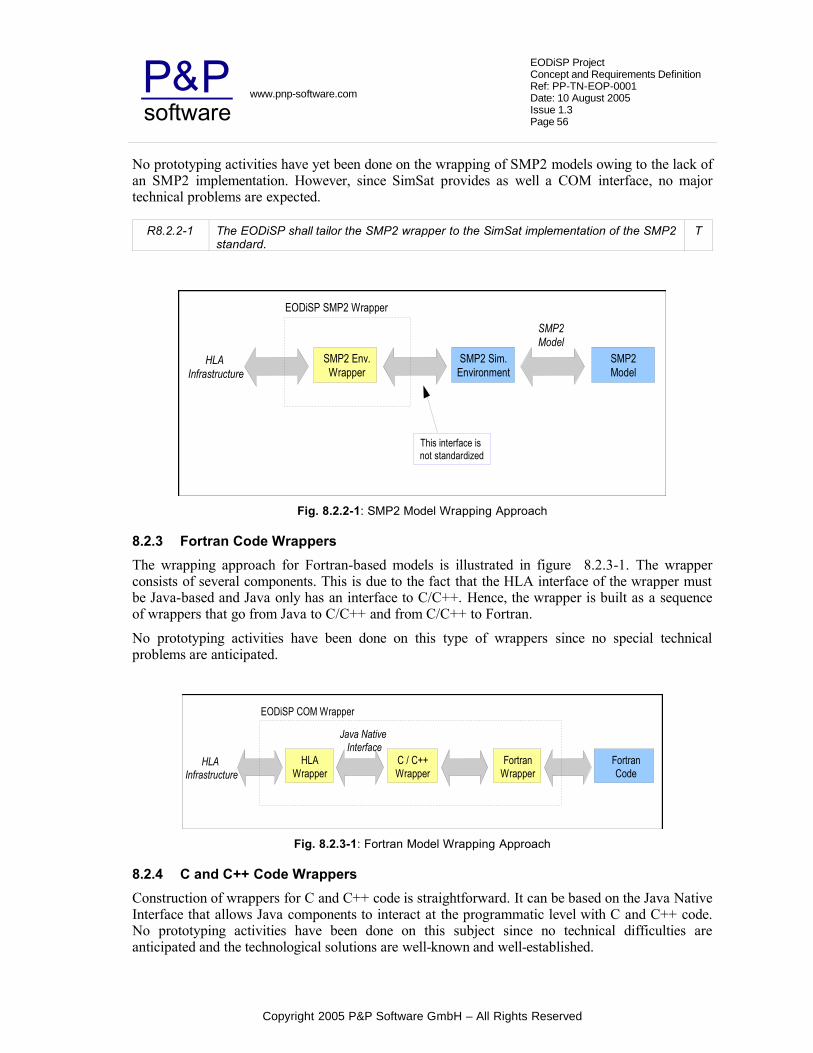
software&PP www.pnp-software.com
EODiSP ProjectConcept and Requirements Definition Ref: PP-TN-EOP-0001Date: 10 August 2005Issue 1.3Page 56
No prototyping activities have yet been done on the wrapping of SMP2 models owing to the lack of an SMP2 implementation. However, since SimSat provides as well a COM interface, no major technical problems are expected.
R8.2.2-1 The EODiSP shall tailor the SMP2 wrapper to the SimSat implementation of the SMP2 standard.
T
SMP2 Env.Wrapper
HLA Infrastructure
EODiSP SMP2 Wrapper
This interface is not standardized
SMP2 Sim.Environment
SMP2Model
SMP2Model
Fig. 8.2.2-1: SMP2 Model Wrapping Approach
8.2.3 Fortran Code Wrappers
The wrapping approach for Fortran-based models is illustrated in figure 8.2.3-1. The wrapper consists of several components. This is due to the fact that the HLA interface of the wrapper must be Java-based and Java only has an interface to C/C++. Hence, the wrapper is built as a sequence of wrappers that go from Java to C/C++ and from C/C++ to Fortran.
No prototyping activities have been done on this type of wrappers since no special technical problems are anticipated.
HLAWrapper
HLA Infrastructure
EODiSP COM Wrapper
C / C++Wrapper
FortranCode
Java Native Interface
FortranWrapper
Fig. 8.2.3-1: Fortran Model Wrapping Approach
8.2.4 C and C++ Code Wrappers
Construction of wrappers for C and C++ code is straightforward. It can be based on the Java Native Interface that allows Java components to interact at the programmatic level with C and C++ code. No prototyping activities have been done on this subject since no technical difficulties are anticipated and the technological solutions are well-known and well-established.
Copyright 2005 P&P Software GmbH – All Rights Reserved

software&PP www.pnp-software.com
EODiSP ProjectConcept and Requirements Definition Ref: PP-TN-EOP-0001Date: 10 August 2005Issue 1.3Page 57
8.2.5 Standalone Executables Wrapping
Construction of wrappers for standalone executables cannot be much facilitated by the EODiSP. The reason is, that the interaction between the model and the EODiSP infrastructure can be almost anything. Therefore, the wrapper code has to be implemented by the person who builds the wrapper.
Figure 8.2.5-1 illustrates the wrapping approach for this type of models. The input/output data outlined in the figure can be anything which supports transferring of input and output data between the standalone executable and the executable wrapper. An example of this can be a database or a file.
Because it is not known what type of facility and what format for the input/output data is used by a certain standalone executable, the wrapper cannot automatically generate any code to access this facility and the data within.
ExecutableWrapper
HLA Infrastructure
EODiSP Executable Wrapper
Input/Outputdata
Not defined.
StandaloneExecutable
Fig. 8.2.5-1: Standalone Executable Model Wrapping Approach
8.3 Prototyping Activities
Although the wrapping problem is regarded as less critical than the framework and distribution problems (see section 3.2), some prototyping activities were also performed in this area to address selected technical issues.
The investigation of the wrapper problem was done in parallel to the investigation of the framework and distribution problems. In order to avoid interference between the two sets of problems, the prototyping activities for the wrapper problem were done on the XRTI. The XRTI (Extensible Run-Time Infrastructure) [Xrti03] is an existing Java-based open source implementation of HLA. The XRTI implements only a subset of the RTI interface defined by HLA. Although this implementation is inadequate to support the needs of the EODiSP, it is mature enough to investigate the wrapper problem.
Three prototypes were built. The first prototype was a complete HLA simulation for a very simple model. This model simply describes the trajectory of a ballistic rocket. The purposes of this first protoype are:
• to gain familiarity with HLA models, and
• to identify the parts of the model wrapper that can be generated automatically.
The first prototype is described in section 8.3.1.
The second prototype aimed at constructing a wrapper for an excel model provided by ESA. In this case, the generation of the wrapper was partly automated. This model is interesting because it is
Copyright 2005 P&P Software GmbH – All Rights Reserved

software&PP www.pnp-software.com
EODiSP ProjectConcept and Requirements Definition Ref: PP-TN-EOP-0001Date: 10 August 2005Issue 1.3Page 58
seen by the EODiSP as a COM object. It is therefore representative of a large class of potential models. The purpose of this second prototype was:
• to demonstrate the XSL-based automatic generation of (part of) a model wrapper, and
• to demonstrate the compatibility of one kind of ESA models with the proposed HLA wrapping approach
The second prototype is described in section 8.3.2.
The work done on the second prototype indicated that there is no available public domain solution to the problem of wrapping a COM object. Existing solutions only have partial functionality. It therefore becamse necessary to investigate the feasibility of developing a Java wrapper for a COM object within the scope of the EODiSP project. The third prototype demonstrates the solution that is proposed to this problem. This prototype again addresses the problem of wrapping an excel model but in this case a simpler excel model is used than was used in the second prototype.
The purpose of the thrid prototype was to demonstrate the feasibility of wrapping COM objects within HLA-compatible Java components. This prototype is discussed in section 8.3.3.
8.3.1 First Prototype – Simple Model Wrapping
This prototype was built around the model of a simple ballistic rocket. Essentially, the case was considered in which there are two rockets that are in flight and and exchange the information about their mass, velocity and position. Each rocket is represented as a federate and they interact through the XRTI. So the federation consists of two rocket federates.
The rocket models are implemented as Java components. Wrappers are required to adapt the components to the interface required by the XRTI. In this first case, the wrappers were written manually. This resulted in a simple but fully working HLA-based simulation.
8.3.2 Second Prototype – ESA Excel Model Wrapping
This prototype was built around an Excel Model provided by ESA. This model consisted of two excel workbooks (Propulstion.xls and MissionAnalysis.xls). Both of these workbooks had some input and output fields and were linked with some common fields. The objective was to generate a wrapper that would combine the two workbooks into the same HLA federate. Additionally, another simple federate called 'Logger' was created. It printed all the data sent to it into a file 'data.txt'. So the Federation consisted of two federates: one federate which wrapped the excel model and another simple 'Logger Federate'.
The following are the main step for the creation of a wrapper:
1) Creation of a Federation Object Model from the given model.
2) Generation of an XML file representing the Federation Object Model.
3) Generation of the wrapper code by parsing the XML file. In this case XSL along with XPath were used for code generation.
Step 1 consists of identifying the object classes participating in the federation, their interactions and their attributes.
The main object classes in this federation are:
Copyright 2005 P&P Software GmbH – All Rights Reserved

software&PP www.pnp-software.com
EODiSP ProjectConcept and Requirements Definition Ref: PP-TN-EOP-0001Date: 10 August 2005Issue 1.3Page 59
1) ExcelModel Class
2) Logger Class
The attributes of the ExcelModel class consisted of all the input and output fields given by the excel models. Since the input fields are neither published nor subscribed by any of the federates, the sharing attribute of these fields is 'neither'. The output fields are published by the 'ExcelModel' federate and are subscribed by the 'Logger' federate so they have their sharing attribute as 'PublishSubscribe'.
The Logger class had no attributes. Both ExcelModel class and the Logger class were shared and publishable.
There is only one interaction class in this federation('KeplerianOrbitOutput') .This class consists of all the output fields which will be sent to the 'Logger' federate as an interaction. It is both shared and published.
In step 2, the Federation Object Model was encoded as an XML file which complies with the DTD of the specific RTI (in this case the XRTI). This XML file is one of the inputs read by the XRTI. It provides all the information the XRTI needs about the federation model.
Finally, in step 3, the XML model is used to generate the wrapper code for the given model. The approach used is the one described in section 8.1. The following items could be generated automatically:
1. For each object class specified in the XML file, a class with the specified attributes is generated.
2. For each generated class, the standard methods getAttribute() and setAttribute() are generated for each of its attributes.
3. A method Calculate() is generated for each class with an empty body. This method acts as a wrapper for the mathematical model and calls the functions from the given model to update the attribute values.
4. A federate with basic functions for connecting to the XRTI, and handles for attributes to be published or subscribed is generated.
5. Object and interaction class handles for the specified object and interaction classes are generated.
Essentially, the only part of the wrapper that cannot be generated automatically is the body of method Calculate. This body has to be implemented manually because it contains the link to the model-specific methods that advance the simulation of the model encapsulated in the excel workbooks.
This prototype was successful in demonstrating that the majority of the wrapper code can be generated automatically but it also highlighted an unexpected problem. The connection from the Java part of the wrapper to the COM object was done using the JACOB API [Jac]. JACOB is a public domain Java-COM bridge. It was found that this bridge was capable of translating property setting operations from Java to COM but it was unable to handle the COM event notification mechanism. Essentially, the Java part of the wrapper becomes unable to react to events that are generated inside the excel models (for instance, it is not possible to react to a change in the value of an excel cell). Several other public-domain implementations of Java-COM bridges were tested but
Copyright 2005 P&P Software GmbH – All Rights Reserved

software&PP www.pnp-software.com
EODiSP ProjectConcept and Requirements Definition Ref: PP-TN-EOP-0001Date: 10 August 2005Issue 1.3Page 60
none was able to handle this problem. Hence, development was started on a dedicated Java-COM bridge. This is the object of the third prototype described in the next section.
8.3.3 Third Prototype – Java-Com Bridge
This prototype focused on the demonstrating an approach to build a Java-COM bridge to help wrap COM-based simulation models. The features needed by the EODiSP to interact with COM objects can be summarized as follows:
• Reading data from a COM Object
• Invoking methods of a COM Object. Not all methods have to be supported.
• Receiving events raised by the COM Object.
The general approach is the one outlined in section 8.2.1. The Java to COM Bridge consists of two main parts: a set of Java classes and a set of C++ classes. The C++ classes are used to access the COM Object. This is the most natural way of accessing a COM object and is well supported. The Java classes are used to interact with the C++ classes from within the Java implementation of the EODiSP.
In order to interact with the C++ classes, JNI (Java Native Interfaces) [Jni] are used. To make this process more generic and convenient to use, some wrapper methods are created. This wrapper method can be called from Java code and will call the appropriate method in the C++ classes. Also supported by the wrapper methods are callback functions to provide the means to call Java methods from within the C++ classes.
The Java and C++ parts of the wrappers run on a dedicated thread and basically wait either for request from the Java side for performing an operation on the COM object, or for a callback from the COM object signalling the arrival of a COM event notification. The COM object runs on its own separate thread.
This prototype uses the Java-COM bridge to access an excel document as a COM object. It demonstrates all three kinds of operations listed above and it in particular demonstrates the ability of the bridge to react to events generated inside the COM object.
Notable for an Excel model are the different elements which can be addressed through a COM object. The following list summarizes them:
• Individual cells
• Address ranges of cells (one or two dimensional)
• Trigger macros.
This list only describes the elements of an Excel model and is not generally supported by a Java COM bridge.
The prototype thus demonstrates the feasibility of building wrappers for COM-based models for the EODiSP.
Copyright 2005 P&P Software GmbH – All Rights Reserved

software&PP www.pnp-software.com
EODiSP ProjectConcept and Requirements Definition Ref: PP-TN-EOP-0001Date: 10 August 2005Issue 1.3Page 61
9 EODiSP IMPLEMENTATION AND OPERATIONAL ASPECTS
Previous sections have investigated the solutions to the main technical issues involved in the development of the EODiSP. The present section consider some implementation and operational aspects and it defines the associated requirements.
9.1 Computational and Memory Requirements
The computational and memory requirements of an EODiSP simulation are expected to be largely determined by the computational and memory requirements of the simulation packages integrated in the simulation. These requirements are outside the control of the developers of the EODiSP.
The requirements of the EODiSP infrastructure will normally be well below those of the models. It is also expected that the requirements of the infrastructure will be well within the level of resources available on any contemporary desktop or workstation.
Hence, there is no need to define specific requirements on the level of computational and memory resources required by the EODiSP.
9.2 Target Operating System
The EODiSP is intended to be portable in the sense that users should be able to run it on different operating systems and hardware platforms. The simplest way to achieve a high level of portability is to build the EODiSP upon the Java platform. This guarantees that the system can be run on any machine where a Java Virtual Machine (JVM) is available. This in practice means that it can be run in any desktop or workstation environment.
Note that the simulation models may be aimed at a specific operating system. Hence, the requirement of portability can only apply to the EODiSP infrastructure, not to an entire EODiSP simulation whose degree of portability depends on the portability of its simulation models.
The choice of the Java platform defines a standardized execution environment for the EODiSP. However, the EODiSP will include a GUI-based part. As discussed below (see section 9.8.2), there may be advantages to building these parts as plug-ins for the Eclipse platform. The question then arises of whether the Eclipse platform itself should be considered as part of the environment upon which the EODiSP runs. The practical implication of such a choice from a user's point of view is that the EODiSP would only run on systems where the Eclipse platform has been installed.
At the time of writing the Eclipse platform is still comparatively rare on user's desktops but it is rapidly gaining in acceptance and it may soon become as ubiquitous as the Java platform. The Eclipse platform itself, on the other hand, is not platform-independent (it is not a pure Java application). Hence, it is possible that there will be some little-used platforms for which it remains unavailable. Since one objective of the EODiSP is to allow integration of simulation models running on as disparate a range of platforms as possible, it would probably be unwise to have a blanket requirement that makes Eclipse an indispensable requirement for the entire EODiSP. A more prudent course of action is to limit the dependency on Eclipse to only the simulation environment part of the EODiSP. This is also the part of the EODiSP that is most likely to require the Eclipse services since it is the part where the most complex GUI-based application will be located (the Simulation Manager Application, see sections 9.5 and 9.8.2).
R9.2-1 The EODiSP shall be built to run on a Java Virtual Machine. T
R9.2-2 The EODiSP shall assume version 1.5 or higher of the Java Virtual Machine. A
Copyright 2005 P&P Software GmbH – All Rights Reserved

software&PP www.pnp-software.com
EODiSP ProjectConcept and Requirements Definition Ref: PP-TN-EOP-0001Date: 10 August 2005Issue 1.3Page 62
R9.2-3 The GUI part of the EODiSP simulation environment may assume the availability of the Eclipse platform on the host computer.
T
R9.2-4 The GUI part of the EODiSP simulation environment shall assume version 3.1 or higher of the Eclipse platform.
A
9.3 Licensing Requirements
The EODiSP is intended to be built as an entirely open and free software platform. This will allow users to inspect its implementation and to customise it as needed. Several free and open software licences have been defined. The one proposed for the EODiSP is the GPL. This is preferred because it ensures that modifications to the EODiSP made by any user become available to the entire EODiSP community. It also helps to avoid a situation where implementations by different communities of users diverge thus giving rise to a situation where maintenance and extensions rapidly become prohibitively expensive.
Obviously, the licensing requirements can only apply to the EODiSP infrastructure since the simulation models may be proprietary.
R9.3-1 The EODiSP shall be provided as a GPL application. A
R9.3-2 Any software that is used either directly or indirectly by the EODiSP shall be compatible with bundling with a GPL application.
A
9.4 Operational Interface – General Concept
This section defines the operational interface of the EODiSP, namely the interface between the EODiSP and its users. The users of the EODiSP are the persons providing the simulation models and the persons setting up and running a simulation.
The main driving factor in defining a concept for the operational interface of the EODiSP is the need to cater for the case of a distributed application where a complete simulation requires applications running on several nodes.
Although the distribution network baselined for the EODiSP (the JXTA, see section 7.5) is a peer-to-peer network, at application level a complete EODiSP simulation is best conceptualized as a client-server architecture where the simulation environment (the “run-time infrastructure” in HLA parlance) acts as the server, and the simulation models (the “federates” in HLA parlance) act as clients which may be located on distributed nodes.
Hence, the operational concept proposed for the EODiSP is based on two applications: the simulation manager and the model manager. The simulation manager can only be instantiated once. It controls the simulation environment (the HLA run-time infrastructure) and acts as the simulation server. The model manager application is instantiated at least once for every distribution node that participates in a simulation. A model manager application controls a set of simulation models (or HLA federates) that reside on the same node. The model managers act as clients to the simulation manager server.
Given this operational concept, two categories of users will participate in an EODiSP simulation. The first type of user is the simulation owner. This is the person who is in overall control of a complete simulation. The simulation owner decides how the simulation models should be configured and when a simulation should start and terminate. The simulation owner interacts with the EODiSP through the simulation manager application.
Copyright 2005 P&P Software GmbH – All Rights Reserved

software&PP www.pnp-software.com
EODiSP ProjectConcept and Requirements Definition Ref: PP-TN-EOP-0001Date: 10 August 2005Issue 1.3Page 63
The second type of user is the model owner. The model owner is a person in charge of one or more simulation models. The model owner decides when to make his simulation models available to a simulation and when to terminate their availability. The model owner interacts with the EODiSP through a model manager application.
Typically, model owners who are prepared to allow their simulation models to be used will start the model manager application on their node. The model manager will then remain in “listening mode” waiting for a simulation manager application to request it to join in a simulation. The model owner can at any time withdraw his models from a simulation by terminating his federate manager application. This mechanism thus ensures that model owners remain in control of their models. This is important in view of the fact that an EODiSP simulation may be made up of a collection of models that belong to different individuals or organizations that may be unwilling to hand over control over them.
A simulation owner operates a simulation through the simulation manager application. He starts an application with the following steps:
• The simulation owner defines the simulation configuration by defining which simulation models participates in a simulation, how they are connected, and how many and which simulation runs should be performed
• The simulation owner activates the simulation,
• The simulation manager application searches for model manager applications that give access to the simulation models required for the simulation and, if it finds it, starts the simulation.
Note that the simulation manager application operates at the level of a simulation experiment, not just of a single simulation run (see section 6.4.1).
Model Mng AModel_A1
Model Owner
Node 1
Model_A2
Model Mng B
Model_B1
Model Mng CModel_C1
Node 2
Model_C2
Simulation Mng
Model Owner
Model Owner
Simulation Owner
Model_A1
Fig. 9.4-1: Simulation Applications
The proposed operational concept is illustrated in figure 9.4-1 for a distributed case. In the case illustrated in the figure, a simulation requires five models. Models A1 and A2 reside on a remote node (node 1 in the figure) and belong to model owner A. Model B1 resides on the same remote node but belongs to a different model owner B. Models C1 and C2 reside on the same node on which the simulation environment resides (node 2 in the figure) and belong to model owner C. In such a configuration, three model manager applications need to be active when the simulation
Copyright 2005 P&P Software GmbH – All Rights Reserved

software&PP www.pnp-software.com
EODiSP ProjectConcept and Requirements Definition Ref: PP-TN-EOP-0001Date: 10 August 2005Issue 1.3Page 64
manager application is started. In the figure, the applications are indicated as green boxes and the simulation models are indicated as yellow boxes.
The simulation and model manager applications are intended to control the operation of an EODiSP simulation. These applications operate at the level of HLA models. The EODiSP however is targeted at simulation packages of the kind defined in section 4. These simulation packages are transformed into HLA federates through the wrapping process defined in section 8.
The HLA does not define how simulation models should be split among model manager applications. The most practical solution is to have one model manager application for each model owner. He can then control all the models he is the owner of through one model manager application. This, however, is just an example of how models can be split. Other ways of splitting them might be more sensible depending on the situation.
As indicated in section 8.1, the wrapper code is partly generated automatically. The code generators are implemented as XSL programs which are provided by the EODiSP. In order to help users in generating this code, a support application is provided the the EODiSP that facilitates the task of running the XSL-based wrapper code generators.
The three kinds of applications provided by the EODiSP – the simulation manager, the model manager, and the support applications – are specified in the next three sections. The specification is done at a high level of abstraction. In particular, all three target applications are GUI-based. However, the exact characteristics of the GUI are not specified. The requirements defined in the next three subsections instead specify the kind of information that the GUI-based applications will manipulate and the type of actions that users must be allowed to perform upon them. The manner in which the information is manipulated and the actions are launched is regarded as an implementation issue and is left open.
It should however be added that, for the two most important applications – the simulation manager and the model manager application – prototypes were developed and are described in sections 10 as part of a general discussion of the typical use scenario of the EODiSP. These prototypes give an idea of the expected “look & feel” of the EODiSP applications.
No prototyping was done for the support application since this application is rather simple and does not present any technical challenges.
R9.4-1 The EODiSP shall provide a Simulation Manager Application to configure and control the execution of a simulation experiment .
T
R9.4-2 The EODiSP shall provide a Model Manager Application to configure and control the participation in simulation experiments of a set of simulation models owned by the same organization and residing on the same distribution node.
T
R9.4-3 The EODiSP shall provide a GUI-based support application to operate the code generators for the simulation model wrappers.
T
9.5 The Simulation Manager Application
The simulation manager application helps the EODiSP simulation owner to perform two tasks. The first task is the configuration of an EODiSP simulation experiment (see section 6.4.1). The second task is the execution of the EODiSP simulation experiment. Each of these two tasks is specified in a dedicated subsection below.
R9.5-1 The Simulation Manager Application shall offer the means to define a configuration for an EODiSP simulation experiment.
T
Copyright 2005 P&P Software GmbH – All Rights Reserved

software&PP www.pnp-software.com
EODiSP ProjectConcept and Requirements Definition Ref: PP-TN-EOP-0001Date: 10 August 2005Issue 1.3Page 65
R9.5-2 The Simulation Manager Application shall offer the means to control the execution of an EODiSP simulation experiment.
T
9.5.1 Simulation Experiment Configuration
A simulation experiment configuration contains the information required to execute a complete simulation experiment consisting of one or more simulation runs performed in sequence.
The simulation manager application offers a GUI-based environment through which users can define a simulation experiment configuration. The configuration information is stored in a set of XML-based documents. The EODiSP defines the XML Schemas to which these documents must conform. The set of configuration files managed by the simulation manager application is defined in table 9.5.1-1. This set does not only specify the configuration files for a simulation experiment but for all tasks which can be performed with the EODiSP simulation manager application.
The first column of table 9.5.1-1 gives the name of the configuration file. The second column gives a brief description of the file's purpose (a more extended description is offered in the text in section 9.5.2). The third column specifies the way in which the file is defined by the simulation manager user. The last column defines the origin of the configuration file.
With reference to the third column of table 9.5.1-1, two definition modes are possible.
With the explicit definition mode, the user must explicitly define the content of the configuration file by directly editing the file as an XML document. The simulation manager application may offer means to support the editing process (e.g. Syntax aware editors, code completion facilities, etc) but the exact extent of this support will be defined as part of the EODiSP implementation. An indication of what can be achieved is provided by the discussion of the application prototype in section 10.2. It is also possible that some parts of the file are generated automatically prior to the configuration.
With the indirect definition mode, the user provides the information required to construct the XML-based configuration document indirectly (e.g. through selection in menus, through entries in text fields activated by wizards, etc). The actual construction of the XML-based document is done automatically by the application.
In all cases, the user has the possibility of loading into the environment an existing configuration file. This allows users to reproduce previous simulation experiments.
With reference to the last column of table 9.5.1-1, two origins for the configuration files are possible. In a first case, the configuration file is defined by the HLA standard and the EODiSP takes it over unchanged (i.e. the EODiSP assumes the same DTD or Schema mandated by the HLA standard). In the second case, instead, the configuration file originates from the EODiSP and is defined internally to the EODiSP.
Table 9.5.1-1: Types of Configuration Files managed by the Simulation Manager Application
File Name Description Def. Mode Origin
SimulationsConfig Stores the configuration tree from an EODiSP simulation manager application (i.e. simulation executions and simulation experiments). This file can be reused to load a complete configuration at a later time.
indirect EODiSP
ExperimentInitConfig Defines the different initialization Explicit EODiSP
Copyright 2005 P&P Software GmbH – All Rights Reserved

software&PP www.pnp-software.com
EODiSP ProjectConcept and Requirements Definition Ref: PP-TN-EOP-0001Date: 10 August 2005Issue 1.3Page 66
File Name Description Def. Mode Origin
parameters for each simulation run defined in a simulation experiment.
FOM Defines object classes, attributes, etc., and the information they exchange at runtime.
indirect HLA
FOMConfig Stores additional informations for a FOM (i.e. interconnections between object and attribute instances).
explicit EODiSP
SOMConfig Stores additional informations for a SOM (i.e. number of instances for every object class and object attribute).
explicit EODiSP
ApplicationSettings Stores general settings configured in the simulation manager application.
indirect EODiSP
SimulationsConfig Configuration FileThis file takes the form of XML and is automatically generated. No user input or changes are required. The purpose of this file is to store the whole configuration tree which has been configured in a simulation manager application. More precisely, this file stores an entry for all currently configured federation executions and simulation experiments. The actual configuration is done in dedicated files within the configuration tree. This file's purpose is mainly to store the order of appearance of all tree entries. Whenever a federation execution is added, removed or reorganized in the simulation manager application, these changes are reflected in this file. The same applies for simulation experiments.
For simulation experiments, this file also holds the order at which simulation runs are executed in a simulation experiment.
Storing this values makes it possible to save the whole configuration and load it at a later time. If this configuration file is read, all information about already configured federation executions and experiments will be available.
It makes it also possible to share the simulation manager configuration with other simulation owners who want to run the same simulation on another node. The EODiSP does not provide any means to accomplish this, but the task will only be to exchange a file and load it into another simulation manager application.
This file does not store application settings because those are dependent on the node on which the application is being run as well as some user preferences.
ExperimentInitConfig Configuration FileA simulation experiment consists of one or more simulation runs. The configuration for a simulation run will be held in the appropriate configuration files for these simulation runs. However, one additional configuration file is needed especially for the simulation experiment. This is because a simulation experiment can have initialization parameters for each simulation run which is included in the experiment. This initialization parameters can be specified in this configuration file.
Copyright 2005 P&P Software GmbH – All Rights Reserved

software&PP www.pnp-software.com
EODiSP ProjectConcept and Requirements Definition Ref: PP-TN-EOP-0001Date: 10 August 2005Issue 1.3Page 67
Section 6.4.1 introduced a so called experiment set including several configuration elements. The ExperimentInitConfig file will reflect such an experiment set. A configuration element will be the initialization parameters which should be used for a simulation run. Initialization parameters can be specified for each model in a simulation run which supports it.
This makes it possible to execute the same simulation run more than once but with different initialization parameters.
Depending on the simulation model in question, initialization parameters can be very different. To cope with this variety, the configuration file holds either primitive values which are sent to the simulation models upon initialization (e.g. an integer value), or a pointer to a file which can be sent. Such a file can include anything the simulation model expects, including binary data.
If the simulation model expects a file, a template file with default values must be attached to it at the time the wrapper is generated. This template file will be transferred to the simulation manager application. A copy of this file will be attached to every occurrence of the simulation model in a simulation experiment. It then can be adjusted or changed to whatever is needed as initialization for each simulation run.
The file takes the form of XML. An XML Schema will formally define the form and content of the file.
FOM Configuration FileThe FOM takes the form of XML and is formally described by a DTD. The formal description is provided by the HLA. The FOM is a specification defining the information exchanged at runtime to achieve a given set of federation objectives. Included in this definitions are object classes, object class attributes, interaction classes, interaction parameters, and other relevant information. The FOM is very similar to a SOM but will be used by the simulation manager application (see section 9.6.2). In this application, it will specify a single federation execution (e.g. 'Solar System (1)'). Each simulation execution will have its own FOM.
The FOM can be generated automatically by using the SOM documents. The relation is as follows: A SOM specifies a single federate and a FOM specifies a federation execution. Since a federation execution consists of one ore more federates, defining the SOM includes a kind of merging all SOM's together into a FOM.
FOMConfig Configuration FileA FOM describes how a simulation execution is assembled concerning object classes and attributes. It does not describe, however, how these classes and attributes are interconnected. This informations will be provided by this configuration file.
A FOMConfig file takes the form of XML and is unique to a single simulation execution. It describes the way how attribute instances of one object class instance are connected to other attribute instances of another object class instance. Possible object instances and their attributes depend on the participating federates and their configuration in a simulation execution. This information will be provided by the SOMConfig files.
Since this file can grow quickly by adding additional federates or specifying more object instances for a certain object class, it is desirable to generate a skeleton for it. This skeleton file will include all possible interconnections. A user then will have to adjust this skeleton file by specifying whether or not to allow a certain interconnection.
Copyright 2005 P&P Software GmbH – All Rights Reserved

software&PP www.pnp-software.com
EODiSP ProjectConcept and Requirements Definition Ref: PP-TN-EOP-0001Date: 10 August 2005Issue 1.3Page 68
As described in section (9.6.2), different facilities can be offered by the application to allow a user to make changes to this configuration file. This, however, does not affect the form or content of this configuration file. It is more a matter of representing data to the user.
SOMConfig Configuration FileThe SOM describes a single federate with its object classes and attributes. It does not, however, include any means to express how many instances of an object class or an attribute shall be included in a simulation execution. The SOMConfig file will provide this information to the EODiSP. This configuration file will therefore be needed in the simulation manager application. A SOMConfig is unique to a single federate included in a simulation execution.
The SOMConfig file takes the form of XML. Other than the FOMConfig, the SOMConfig file will not grow much. It only depends on the number of object classes in a federate. Still, to avoid mistakes during the configuration, it is desirable to have a skeleton file providing the user with a list of all possible object instances he can choose from. The configuration task will be to specify the number of desired instances for each object class.
The SOMConfig will be a source to generate the skeleton file for the FOMConfig because it includes the informations needed to specify the interconnections between object and attribute instances.
As for the FOMConfig, several facilities are possible for the visual representation of the data included in this configuration file.
ApplicationSettings Configuration FileThis is a configuration file almost every application would need. It holds application specific settings. Therefore, this file is unique to a single application. In this case, this file will hold general settings about the simulation manager application.
The content of the file can be adjusted or extended according to the needs of the application. At least, the network and user settings (e.g. language) settings will be included in this file.
The ApplicationSettings file will take the form of XML.
R9.5.1-1 The simulation manager application shall provide a GUI-based environment to define the configuration of a simulation experiment.
T
R9.5.1-2 The configuration of a simulation experiment shall be defined through a set of XML-based documents.
A
R9.5.1-3 The EODiSP shall define the XML Schemas or DTD's to which the configuration documents used in the simulation manager application must conform.
A
R9.5.1-4 The simulation manager application shall support the definition of the configuration files defined in table 9.5.1-1.
T
R9.5.1-5 The simulation manager application shall allow users to load existing configuration files into the environment.
T
9.5.2 Simulation Experiment Execution
The simulation manager application offers a GUI-based environment through which an EODiSP simulation owner can launch and control the execution of a simulation experiment. The specific tasks that can be performed through this environment are listed in table 9.5.2-1.
Copyright 2005 P&P Software GmbH – All Rights Reserved

software&PP www.pnp-software.com
EODiSP ProjectConcept and Requirements Definition Ref: PP-TN-EOP-0001Date: 10 August 2005Issue 1.3Page 69
Table 9.5.2-1: Types of Task in the Simulation Manager Application
Task Description
Experiment Start Start execution of a simulation experiment
Experiment Abort Abort execution of a currently running simulation experiment
Mode Switch Switch between step-by-step and continuous execution mode (see section 6.4.2)
Step Through Step through execution of a simulation experiment (see section 6.4.2)
Enable / Disable Logging
Enable or disable logging (see section 6.4.4)
Define Log Configuration
Define which type of data should be logged (see section 6.4.4)
R9.5.2-1 The simulation manager application shall provide a GUI-based environment through which users can perform the tasks defined in table 9.5.2-1.
T
9.6 The Model Manager Application
The model manager application helps the EODiSP model owner to perform two tasks. The first tasks is to include federates (i.e. SOM files representing a model) into the application. This is the configuration task of this application. The second task is to manage federates to make them available to EODiSP simulation manager applications or to withdraw them from a running federation execution. This task will be referred as the execution task of this application, even though it is also a configuration task. The difference is, that it will have an effect on a running simulation experiment.
If simulation models have been made available to certain simulation manager applications, it needs to run continuously until the model owner decides to quit and therefore withdraw all models from EODiSP network.
R9.6-1 The Model Manager Application shall offer the means to load HLA compliant models and to make the application aware of them.
T
R9.6-2 The Model Manager Application shall offer the means to control the accessibility of HLA compliant models loaded into the application.
T
9.6.1 The Model Manager Configuration
The model manager application offers a GUI-based environment through which users can manage their models. The configuration information is stored in a set of XML-based documents. The EODiSP defines XML Schemas for all of these XML-based documents.
Table 9.6.1-1 lists the configuration files managed by the model manager application. A description of the columns used in the table is given in the section about the simulation manager application (see section 9.5.1).
A more detailed description about form and content of each individual configuration file is given in the text below the table.
Copyright 2005 P&P Software GmbH – All Rights Reserved

software&PP www.pnp-software.com
EODiSP ProjectConcept and Requirements Definition Ref: PP-TN-EOP-0001Date: 10 August 2005Issue 1.3Page 70
Table 9.6.1-1: Types of Configuration Files managed by the Model Manager Application
File Name Description Def. Mode Origin
ModelsConfig Stores the configuration tree of federates which are included in the model manager application and the path to find them.
indirect EODiSP
SOM Stores information about object classes and object class attributes of a single federate.
indirect HLA
SOMSecuritySettings Stores information about the accessibility of a single federate.
indirect EODiSP
ApplicationSettings Stores general settings configured in the model manager application.
indirect EODiSP
ModelsConfig Configuration FileThis file stores the the whole configuration tree of a model manager application. Whenever a federate is added, removed or relocated, these changes are reflected in this file. A model manager application can load this file at a later time to reuse an already made configuration. Because models usually belong to a certain node (i.e. they reside only on one computer), this file is not intended for distribution. The problem would be, that federate can not be found on the remote computer. Even though, if the same models reside on the same path on a remote computer, this file could be reused there to load a configuration. The EODiSP provides no means to accomplish this.
The file itself stores no configurations. It will list entries for every federate which is included in the application. The configuration of these federates will be stored in dedicated files.
The file will take the form of XML. No user inputs or changes are required for this configuration file.
SOM Configuration FileThe SOM configuration file takes the form of XML and is formally described by a DTD. The formal description is provided by the HLA. The SOM is a specification of the types of information that an individual federate could provide to the HLA federations as well as the information that an individual federate can receive from other federates in HLA federations. Therefore, it is used to specify one single federate. The model manager application will use this configuration files to load a federate and to make it available to the EODiSP network.
SOMSecuritySettings Configuration FileThis file controls the (remote-) accessibility of all provided federates by a model manager application. With this control, a certain model (or federate) can be made accessible to only certain simulation manager applications.
The model owner who runs the model manager application does not need to change this file directly. It will be automatically generated and updated upon changes. The model owner just have to specify, for each federate, if and from which simulation manager application a federate shall be accessible. This can be done directly through the graphical user interface.
Copyright 2005 P&P Software GmbH – All Rights Reserved

software&PP www.pnp-software.com
EODiSP ProjectConcept and Requirements Definition Ref: PP-TN-EOP-0001Date: 10 August 2005Issue 1.3Page 71
The identification for the simulation manager applications among which the model owner can choose is a text representing the name of it. The EODiSP will internally identify these applications with a unique number to avoid intersections. This means, that the model owner needs to know the name of the simulation manager applications which can access his simulation models. If two simulation manager applications chose the same name, the model manager application can show more information such as network address or the name of the simulation owner.
The SOMSecurtiySettings file takes the form of XML.
ApplicationSettings Configuration FileThis is a configuration file almost every application would need. It holds application specific settings. Therefore, this file is unique to a single application. In this case, this configuration file holds the general settings made in the model manager application.
The content of the file can be adjusted or extended according to the needs of the application. At least, the network and user settings (e.g. language) settings will be included in this file.
The ApplicationSettings file will take the form of XML.
R9.6.1-1 The model manager application shall provide a GUI-based environment to define the accessibility configuration for HLA compliant models.
T
R9.6.1-2 The configuration of a model manager application shall be defined through a set of XML-based documents.
A
R9.6.1-3 The EODiSP shall define the XML Schemas or DTD's to which the configuration documents used in the model manager application must conform.
A
R9.6.1-4 The model manager application shall support the definition of the configuration files defined in table 9.6.1-1.
T
R9.6.1-5 The model manager application shall allow users to load existing configuration files into the environment.
T
9.6.2 Model Manager Execution
The model manager application offers a GUI-based environment through which a model owner can manage all HLA compliant models currently accessible on the file system. These models may reside on the local or on a remote computer. If the models reside on a remote computer, the model owner has to make sure that these models can be used (accessed and executed) from the local computer. The model manager application or the EODiSP provide no means to accomplish this.
Table 9.6.2-1 shows the tasks which can be performed by a model manger application.
Table 9.6.2-1: Types of Task in the Model Manager Application
Task Description
Load Configuration Load an already existing configuration.
Load Federate Load an HLA compliant federate into the model manager application.
Make Federate Available
Make the federate available to the EODiSP network.
Manage Federate Access
Define which federate should be made accessible by which simulation manager application.
Withdraw Federate Withdraw a federate from a running simulation experiment.
Copyright 2005 P&P Software GmbH – All Rights Reserved

software&PP www.pnp-software.com
EODiSP ProjectConcept and Requirements Definition Ref: PP-TN-EOP-0001Date: 10 August 2005Issue 1.3Page 72
R9.6.2-1 The model manager application shall provide a GUI-based environment through which users can perform the tasks defined in table 9.6.2-1.
T
9.7 The Support Applications
The support applications help a model owner to convert simulation packages to HLA compliant federates. To do so, he first needs to create a new package (or he uses one which is already available). A simulation package can be one of those types identified in section 4.1. The problem is, that such a package does not conform to the HLA standard and cannot be used in such an environment. Since the EODiSP makes use of the HLA standard, it is necessary to convert simulation packages to an HLA compliant federate. Various support applications will be built to assist the model owner to do so.
Making a simulation package HLA compliant involves creating an additional layer on top of the package. This layer will vary, depending on the type of package. The target of this layer is to build an interface (i.e. the wrapper code) through which the simulation package can communicate to the HLA world and vice versa. More detailed information about this topic is given in the discussion about the wrapper problem in chapter 8.
Creating such an interface can be a difficult task, depending on the type of package. It is further not possible to build it fully automatically. A support application will need specific information to automate the process of building necessary code.
In addition to creating the wrapper code, a SOM document needs to be created as well. This document is defined by the HLA and exactly specifies the nature of a single federate. This document will be needed later by the model manager application (see Table 9.7-1).
Another task which is optional because it depends on the simulation model is to create default initialization data for the simulation model. These data are either of primitive types or a file on the local file system. Creating such default data makes it possible to attach them to the model and change them later in the simulation manager application. This is needed to have different initialization data for a simulation experiment where a simulation run should be executed several times.
R9.7-1 A Support Application shall offer the means to assist a model owner in creating wrapper code for supported types of models. The wrapper code shall be HLA compliant.
T
R9.7-2 A Support Application shall offer the means to automatically create a SOM document for the model whose wrapper code is being generated.
R9.7-3 A Support Application shall offer the means to attach default initialization data to a simulation model. These data can be either of primitive types or they can be defined in a file.
9.7.1 Support Application Configuration
A support application offers a GUI-based environment through which the user can create HLA compliant federate. There will be a dedicated support application for each type of simulation package.
The configuration of a support application consists of writing a single document. Since there is a dedicated application for each type of simulation package, the content and form of this document will vary. It will reflect the needs of a support application to automatically generate as much of the wrapper code as possible.
Copyright 2005 P&P Software GmbH – All Rights Reserved

software&PP www.pnp-software.com
EODiSP ProjectConcept and Requirements Definition Ref: PP-TN-EOP-0001Date: 10 August 2005Issue 1.3Page 73
Table 9.7.1-1 gives an overview of the configuration files involved in a support application. A description of the columns used in the table is given in the section about the simulation manager application (see section 9.5.1).
A more detailed description about form and content of each individual configuration file is given in the text below the table.
Table 9.7.1-1: Types of Configuration Files managed or produces by a Support Application.
File Name Description Def. Mode Origin
WrapperConfig Stores information needed by a support application to create appropriate wrapper code. The content of this file varies depending on the type of model.
explicit EODiSP
WrapperConfig Configuration FileThis file will take the form of XML. The content of this file depends on the type of model for which the wrapper code should be generated. As described in the example above, for some types of models a scripts can be provided to aid the user in creating this file. If no script is available, the support application will provide appropriate means to create this configuration file.
R9.7.1-1 A Support Application shall provide a GUI-based environment to support a model owner in creating the wrapper code.
T
R9.7.1-2 The configuration of a Support Application shall be defined through a set of XML-based documents.
A
R9.7.1-3 The EODiSP shall define the XML Schemas or DTD's to which the configuration documents used in a Support Application must conform.
A
R9.7.1-4 A Support Application shall support the definition or creation of the configuration files defined in table 9.7.1-1.
T
R9.7.1-5 A Support Application shall allow users to load existing configuration files into the environment.
T
9.7.2 Support Application Execution
A support application offers a GUI-based environment through which a model owner can create the wrapper code for one of the predefined model types. Table 9.7.2-1 defines the tasks which can be performed through this environment.
Table 9.7.2-1: Types of Task to control a support application
Task Description
Create the Wrapper Code
Runs the code generator which will produce the wrapper code.
Create SOM Document
Creates a SOM Document which is specified by the HLA. This document will be used to identify and specify a certain federate.
Load Configuration Loads an existing WrapperConfig document which will be used to generate the wrapper code.
R9.7.2-1 A Support Application shall provide a GUI-based environment through which users can T
Copyright 2005 P&P Software GmbH – All Rights Reserved

software&PP www.pnp-software.com
EODiSP ProjectConcept and Requirements Definition Ref: PP-TN-EOP-0001Date: 10 August 2005Issue 1.3Page 74
perform the tasks defined in table 9.7.2-1.
9.8 EODiSP Configuration Files Summary
The previous sections introduced the configuration files needed by the EODiSP. This section summarized the configuration for the whole EODiSP framework.
Table 9.8-1 gives an overview of all configuration files which were introduced throughout this chapter. The first column gives the name of the configuration file, the second column gives a short description of its purpose. The third column shows which application makes use of the configuration file. For this column, three options are possible:
• SM: Simulation Manager Application
• MM: Model Manager Application
• SA: Support Application
The fourth column states the origin of the configuration file, that is, by whom the configuration file is defined. Two values are possible:
• EODiSP: The configuration file is defined by the EODiSP framework.
• HLA: The configuration file is defined by the HLA standard. This definitions will be left untouched by the EODiSP.
This overview is meant as an orientation help concerning the configuration of the EODiSP. A more detailed description of the configuration files is given in dedicated section above.
Table 9.8-1: Summary of all Configuration files managed by the EODiSP
File Name Description Used By Origin
SimulationsConfig Stores the configuration tree from an EODiSP simulation manager application (i.e. simulation executions and simulation experiments). This file can be reused to load a complete configuration at a later time.
SM EODiSP
ExperimentInitConfig Defines the different initialization parameters for each simulation run defined in a simulation experiment.
SM EODiSP
FOM Defines object classes, attributes, etc., and the information they exchange at runtime.
SM HLA
FOMConfig Stores additional informations for a FOM (i.e. interconnections between object and attribute instances).
SM EODiSP
SOMConfig Stores additional informations for a SOM (i.e. number of instances for every object class and object attribute).
SM EODiSP
Copyright 2005 P&P Software GmbH – All Rights Reserved

software&PP www.pnp-software.com
EODiSP ProjectConcept and Requirements Definition Ref: PP-TN-EOP-0001Date: 10 August 2005Issue 1.3Page 75
File Name Description Used By Origin
ApplicationSettings Stores general settings configured in the simulation manager application.
SM/MM/SA EODiSP
ModelsConfig Stores the configuration tree of federates which are included in the model manager application and the path to find them.
MM EODiSP
SOM Stores information about object classes and object class attributes of a single federate.
SM/MM HLA
SOMSecuritySettings Stores information about the accessibility of a single federate.
MM EODiSP
WrapperConfig Stores information needed by a support application to create appropriate wrapper code. The content of this file varies depending on the type of model.
SA EODiSP
The next two figures try to visualize the structure of the configuration files use in the simulation and model manager application. This should also help to associate certain configuration files to an application and also to find the location within an application.
Copyright 2005 P&P Software GmbH – All Rights Reserved

software&PP www.pnp-software.com
EODiSP ProjectConcept and Requirements Definition Ref: PP-TN-EOP-0001Date: 10 August 2005Issue 1.3Page 76
EODiSP
ApplicationSettings
Federation Executions
Simulation Experiments
FOM
FOMConfig
Federation Execution 1
Federate 1
SOM
SOMConfig
SimulationsConfig
Simulation Experiment 1
ExperimentInitConfig
Fig 9.8-1 Structure of the configuration files in the simulation manager application
It is not meant that the graphical representation in a GUI-based environment must have the same tree structure as those in the figures. The transformation of this trees to a GUI-based environment is an implementation issue. Although it is likely that it will take the form of a tree structure since it is a common way to represent these kinds of data.
Figure 9.8-1 shows this tree for the simulation manager application. You will find a very similar structure in the GUI-based prototype version of this application (see section 9.8.2).
Figure 9.8-1 shows the same tree for the model manager application.
There is no figure for the support applications since there is only one configuration file and therefore no tree to be shown.
Copyright 2005 P&P Software GmbH – All Rights Reserved

software&PP www.pnp-software.com
EODiSP ProjectConcept and Requirements Definition Ref: PP-TN-EOP-0001Date: 10 August 2005Issue 1.3Page 77
EODiSP
ApplicationSettings
Federate 1
SOM
ModelsConfig
SOMSecuritySettings
Federate 2
SOM
Fig 9.8-2 Structure of the configuration files in the model manager application
9.9 Configuration Files Use Scenario
This section describes a use case where a model manager builds a new model, creates the wrapper code and configuration files, integrates it in the model manager application and makes it available to the EODiSP network. On the other side, a simulation manager integrates this newly created model in the simulation manager application and creates all necessary configuration files for it. This use scenario corresponds to the one given in chapter 10 but with a focus on the configuration files. Whenever the text refers to a graphical user interface, those screenshots given in chapter 9.6 are referenced.
This use scenario will not repeat the previous section. It will only give an overview of the workflow concerning the configuration.
Once a model manager has created a new model (one of the type identified in section 4.1), he will use (if available) helper scripts to build the WrapperConfig file. Using this file and the model, he then will use the appropriate support application to generate the wrapper code to make the model HLA compliant. This support application can also build the SOM. Depending on the type of simulation package, the model owner has to chose from different, dedicated support applications. Additionally, the support application provides the means to attach default initialization data to the simulation model. An example for one type of simulation package is as follows.
Consider the case where a model owner wants to convert an Excel Model to an HLA compliant federate. Technically, Excel models can be regarded as COM objects (see section 8.2.1). Therefore, a wrapper needs to be built to access the COM object. The wrapper on its own could be built automatically, the problem is, that the support application does not know which Excel cells (or cell ranges) are to be taken into account.
To make this information available to the support application, a configuration file must be created prior to generating the code. In the case of this excel example, a Visual Basic script can be provided which helps selecting Excel fields as either input or output fields. This script can automatically build the configuration file needed by the support application. Note that such a script would be only an additional help for the user. The configuration could also be done without it.
To integrate this HLA compliant model into the model manager application, the model manager starts the application and chooses the generated SOM through a file dialog to make it aware of the
Copyright 2005 P&P Software GmbH – All Rights Reserved

software&PP www.pnp-software.com
EODiSP ProjectConcept and Requirements Definition Ref: PP-TN-EOP-0001Date: 10 August 2005Issue 1.3Page 78
model (which is now a federate, in HLA parlance). The model manager can now choose which simulation manager applications will have access to this model, if any. Those options will be written to the SOMSecurtiySettings file.
Additionally to the settings above, the model manager can also make adjustments to the general settings (like network settings, language, etc.) which will be reflected in the ApplicationSettings file for his model manager application. This can be done at any time. No other configuration tasks need to be done by the model manager.
On the other side, the simulation manager wants to integrate the newly created federate from above to his simulation manager application in order to use it in a simulation execution.
To do this, he will first search for available models. If the application finds the model in question, the simulation manager can use it, provided that he has sufficient permissions. The fact that a federate is available will be displayed in the simulation manager application.
To integrate the federate into a simulation execution, the simulation manager can add a federate by selecting it from the list of available federates and dragging and dropping it into the tree folder of the appropriate simulation execution. What happens by this drag and drop operation is, that the SOM file is transferred from the model manager application to the simulation manager application.
The simulation manager additionally has to define the SOMConfig and FOMConfig. First, he changes the SOMConfig file to his needs, giving information about how many object and attribute instances he wishes to create and after that, he will make changes to the FOMConfig files specifying the interconnections between different object class instances and their attributes. For both files, a skeleton will have been created automatically. The simulation manager application will update the FederationExecutionsConfig as needed without any user interaction.
An important note is, that a single federation execution cannot be started independently without creating a simulation experiment. EODiSP supports the means to start an experiment only. This is to make the configuration process more consistent. The simulation owner will always be asked to configure a simulation experiment, whether he wants to run only single federation execution or a sequence of such executions. Therefore, the simulation manager needs to create a new (or choose an already existing) simulation experiment. He then adds the federation executions which shall participate in the experiment in the order he wishes them to start.
If the simulation owner creates a new simulation experiment, he will have to adjust the default initialization parameters for simulation models which support it (i.e. simulation models which have initialization data). The document to change is the ExperimentInitConfig
As with the model manager application, the simulation manager can adjust the general settings for the application at any time he wishes. These changes are reflected in the ApplicationSettings file of the application.
Copyright 2005 P&P Software GmbH – All Rights Reserved

software&PP www.pnp-software.com
EODiSP ProjectConcept and Requirements Definition Ref: PP-TN-EOP-0001Date: 10 August 2005Issue 1.3Page 79
10 EODiSP Use Scenario
The requirements in the previous subsections define the mode of operation of the EODiSP at a high level of abstractions. Definitions of lower-level requirements covering, for instance, the exact layout of the simulation and model manager GUIs or the number and type of commands that they should offer to the user is regarded as counterproductive at this stage for two reasons.
The first reason is that the detailed mode of operation of the simulation and model manager applications should be optimized based on the implementation of the two applications and this implementation will only be defined during the EODiSP development phase.
The second reason is that, once the framework and distribution infrastructures are implemented, the implementation of the simulation and model manager applications is not expected to present any technical problems. Hence, there is no special advantage from investing time in evaluating alternative solutions for these applications during a prototyping phase.
However, in spite of the above and in order to offer a complete overview of the concept proposed for the EODiSP, it was judged useful to present a possible mode of operation of the simulation and model manager applications. This helps to understand the mode of use of the EODiSP as a whole. This section presents such a mode of operation for both applications. It should be stressed that this mode of operation, though compliant with the requirements defined in other parts of this document, is not the only possible solution that satisfies these requirements. It is presented here for information only and to better illustrate the overall EODiSP concept. The actual mode of operation of the simulation and model manager applications will be defined in the course of the EODiSP development.
For both the simulation and model manager applications simple prototypes of their user interface have been built and are available as part of the EODiSP prototype data package deliverable (see section 3.5).
Subsection 10.1 discusses the mode of operation of the model manager application. Subsection 10.2 discusses the mode of operation of the simulation manager application. Subsection 10.3 presents a complete use scenario for the entire EODiSP.
10.1 Model Manager Application Prototype
The model manager application is used by the model owner (the individual or entity owning one more simulation models) to manage his models and to make them available over the internet for inclusion in a simulation.
The model manager application prototype is implemented as a Java GUI application. This choice has the advantage of portability. This is very important since the model manager application must be capable of running on a wide array of different platforms.
Figure 10.1-1 shows a screenshot of the application prototype. On the left panel, a number of hierarchically organized items are listed. The user selects one of these items and, based on his selection, the display in the panel at the top in the right window is modified. In most cases, the content of this panel is simply a configuration panel where the user is asked to specify a number of configuration details. Thus, for instance, if the user selects the “network setting” entry, then a configuration panel appears where the user is asked to specify the network characteristics of the node on which he resides (see figure 10.2-1 for an example from the simulation manager application).
Copyright 2005 P&P Software GmbH – All Rights Reserved

software&PP www.pnp-software.com
EODiSP ProjectConcept and Requirements Definition Ref: PP-TN-EOP-0001Date: 10 August 2005Issue 1.3Page 80
Fig. 10.1-1: Model Manager Application Prototype Screenshot
The main function of the model manager application is to make models available for inclusion in a running simulation. For this purpose, the left-hand panel offers two directories: “simulation models” and “available models”. The first contains all the models that are under the control of the model owner who is running the application. The second one contains all the models that the model owner chooses the make available for a simulation. The user moves models between the two directories by dragging and dropping them.
An important question that arises in this connection is: what exactly is a model? Namely, what is it that is stored in the “simulation models” and “available models” directories. In order to answer this question, it is necessary to consider that, in the proposed EODiSP concept, simulation models exist at two levels (see figure 10.1-2).
The first level is the “native level”. At this level, models exist in their native form. They can be excel files, executable files, C++ classes implementing one or more SMP2 interfaces, etc. Essentially, at the native level, all the type of models identified in section 4.1 will be found. Other types of models are also possible since this level is not standardized.
The second level is the “HLA level”. At this level, models exist in a form ready for inclusion in an HLA simulation. Their form is therefore standardized as specified by the HLA architecture. A model makes the transition from the native to the HLA level through the wrapping process.
It is proposed that the model manager application operate at the HLA level. This is preferable because this level is standardized and therefore it is the only level at which a generic application can work. At the HLA level, a model is described, in accordance with the HLA standard, by its Simulation Object Model or SOM. Hence, the entities that are handled by the model manager application are SOM files (implemented as XML documents).
Copyright 2005 P&P Software GmbH – All Rights Reserved

software&PP www.pnp-software.com
EODiSP ProjectConcept and Requirements Definition Ref: PP-TN-EOP-0001Date: 10 August 2005Issue 1.3Page 81
Note that, as explained in section 9.5, dedicated applications will be provided to support the wrapping process for selected types of native models. It is an open question whether these applications should be somehow incorporated in the model manager application. The current baseline is to keep them separate. This choice is dictated by the wide diversity of native model types which are difficult to manipulate in a uniform manner from a singe application.
Fig. 10.1-3: HLA and Native Level of Simulation Models
Another important function of the model manager application is indicated by the bottom panel in figure 10.1-1. This panel serves as a console where log messages are displayed. The user can select the kind of log messages that are to be displayed and can ask for them to be sent to a log file. The log messages are intended to provide the model owner with an overview of when, by whom and how his model is used. Log messages can for instance alert the model owner as to when his federate is included in a simulation and as to which kind of data it receives and sends out to other federates.
10.2 Simulation Manager Application Prototype
The simulation manager application is used by the simulation manager (the individual or entity responsible for running a simulation) to configure and control execution of a simulation.
Like the model manager application, and for the same reasons of portability, the model manager application prototype is implemented as a Java GUI application.
Figure 10.2-1 shows a screenshot of the application prototype. Its structure is similar to that of the model manager application. One important difference is that there are more menus on the top bar. One important such menu is the 'Configuration' menu which is used to query the model manager applications that are currently available for a list of available models. These available models are then stored under the “available models” directory on the left-hand panel. The user can refresh this list at any time to reflect changes in the availability status of the models.
Once the list of available models has been completed, the user can set up one or more federations. In accordance with the HLA architecture, each federation represents a simulation configuration. Each federation is built by defining the model instances that participate to it and the way they are interconnected. Note that the proposed structure of the application allows a user to simultaneously define and maintain more than one simulation configuration.
Copyright 2005 P&P Software GmbH – All Rights Reserved
Federate
Model_A1
Native Level
Excel Model Model_A1Exec Model Model_A1SMP2 Model Model_A1. . . Simulation Package
HLA LevelWrappingProcess
WrappingProcess
WrappingProcess
WrappingProcess
Federate Federate Federate

software&PP www.pnp-software.com
EODiSP ProjectConcept and Requirements Definition Ref: PP-TN-EOP-0001Date: 10 August 2005Issue 1.3Page 82
Fig. 10.2-1: Simulation Manager Application Prototype Screenshot
Once the federations have been set up, they can be run through the “run” menu. This menu allows the user to start, stop, hold and step through a simulation. In addition, the application will provide a means of visualizing the status of a currently running simulation. That is, it will display the federate which is currently active.
One important issue concerns the facilities to be offered by the application to allow users to define the configuration of a simulation. As discussed in section 9.4, this configuration is encoded as an XML document. The simplest solution is therefore for the user to encode it by directly editing this document. This can be done in the large panel on the right-hand side of the simulation manager application. In order to facilitate the task of the user, the application will implement a syntax-aware XML editor in this panel. This will provide code-completion facilities that will allow users to quickly fill in the XML document. Additionally, the application will offer commands to validate the file thus defined.
Two alternative solutions are possible. The first one is based on the provision of a “drawing form” where users can construct the simulation configuration by positioning icons representing the simulation models on a canvas and linking them graphically through lines representing data paths. The drawing form is best built on top of a graphical framework such as Eclipse's GEF.
The second solution is to construct an ecore model of the simulation configuration and then let users use the facilities offered by the EMF Eclipse plug-in to manipulate and construct a new
Copyright 2005 P&P Software GmbH – All Rights Reserved
software&PP www.pnp-software.com
EODiSP ProjectConcept and Requirements Definition Ref: PP-TN-EOP-0001Date: 10 August 2005Issue 1.3Page 83
configuration. This solution is less user-friendly than the previous one but it is still superior to the base XML editing one baselined above2.
These two solutions are not baselined for use because they both rely on the use of an Eclipse plug-in. This is problematic in the EODiSP context because the Eclipse platform is not platform-independent. Its use would therefore break one of the fundamental requirements of the EODiSP, namely its assumption of platform-independence. These solutions would become possible only if it were accepted to relax the assumption of platform independent by deciding to make the simulation model manager (but not the simulation models or the model manager applications) platform-dependent.
Finally, as in the case of the model manager application, the simulation manager application provides extensive logging facilities and a console-like panel is provided at the bottom of the application GUI.
10.3 Typical EODiSP Use Scenario
A typical use scenario for the EODiSP will involve one simulation manager and one or more simulation model owner. The EODiSP allows these actors to operate independently of each other. Let us then first consider the typical actions that would be performed by a model owner.
A model owner would proceed as follows. He would first collect his models in native form. He would then wrap them to turn them into HLA models. In the wrapping operations he will often be assisted by the support applications provided by the EODiSP (see section 9.5). After the models are available as HLA models, they are ready to be imported in the EODiSP environment. The model owner can do this by starting his model manager application and then importing his models. The model owner will then decide which of these models he wishes to make available.
At this point, the model owner does not have to take any further action. He can monitor the model manager application that will inform him when and if any of his models are used by a simulation and he can see and log the data they receive and generate. He can also and at anytime withdraw a model from a running simulation. This may cause the entire simulation to collapse but the EODiSP is built as a cooperative environment where a simulation runs only as long as all its participants are willing to contribute to it.
On the simulation manager side, the basic steps are as follows. The simulation manager starts the simulation manager application and, after performing general configuration tasks, he will asks the application to search the network for available model. The application builds up a list of all application models that are currently available for inclusion in a simulation. The simulation manager then constructs the federations representing the simulations which he may want to run. Each federation is built by importing the necessary simulation models and by then defining their mutual interconnections. After the federation has been configured (see section 9.7), the simulation manager can start the simulation. He can also hold a running simulation or he can step through the simulation for debugging purposes. Once again it is stressed that continuation of the simulation depends on all participating models remaining continuously available throughout the simulation run.
Another important consideration is the fact, that if multiple simulation manager applications are running at the same time, it is possible that more than one simulation execution would want to use the same federate. The EODiSP framework overcomes this problem by locking a federate which
2P&P Software have extensive experience implementing both kinds of solutions. The first solution is implemented in the XFeature tool [XFe]. The second one is implemented in the XWeaver tool [XWe]. Readers can refer to these tools for an impression of how these solutions would look like to the user.
Copyright 2005 P&P Software GmbH – All Rights Reserved

software&PP www.pnp-software.com
EODiSP ProjectConcept and Requirements Definition Ref: PP-TN-EOP-0001Date: 10 August 2005Issue 1.3Page 84
participates in a running simulation execution. If a federate is locked by a simulation execution, no other simulation execution including the same federate can be started. It must wait to start until the other simulation execution has completely finished.
Note finally that the simulation manager does not really see how the simulation proceed. The simulation manager application will log special events but the display and logging of the values of the simulation variables is not done by this application. This is the task of a simulation model of type “data processing package” (see section 4.1). The simulation manager application is only responsible for controlling the execution of the simulation.
Copyright 2005 P&P Software GmbH – All Rights Reserved

software&PP www.pnp-software.com
EODiSP ProjectConcept and Requirements Definition Ref: PP-TN-EOP-0001Date: 10 August 2005Issue 1.3Page 85
11 EODiSP Error Handling
Especially in a distributed environment such as the EODiSP, several errors can occur during execution of a simulation experiment. The most notable situation is when the network is not available due to a connection error. The EODiSP will introduce some mechanisms to cope with these situations.
11.1 Network Errors
There are mainly two different types of network errors which can occur in the EODiSP when running it in a distributed environment. The first type is a connection error, where at least one node is no longer reachable through the network. The EODiSP will provide mechanisms to discover them and to log them. The second type is a transfer error. This occurs when a message is transferred between a sender and a receiver, but the message cannot be transferred without errors. Because the EODiSP uses standard transport protocols to transfer messages, it cannot provide any special facilities to handle these types of errors.The next subsections will discuss these two types of network errors in more detail.
11.1.1 Connection Error
There are several reasons for network errors which the EODiSP cannot control. Among others, network failures occur if the ISP (Internet Service Provider) has technical problems, the network cable is broken or a model owner has simply withdraw his models from a running simulation experiment.
Since the EODiSP depends on the availability of remote federates and vice versa, such a failure leads to an impossibility to finish a simulation experiment. The EODiSP will introduce some error handling facilities to handle this type of errors. This facility will not be able to recover such errors at any rate, but it will help to react on them.
The proposed solution is to implement a monitoring facility for all applications participating in a simulation experiment. Namely these are the simulation manager and one or more model managers with their federates included. Each of these applications will make use of the monitoring facility provided by EODiSP. For the model manager application, the monitoring facility will not be implemented for every federate, but only for the application itself. It will know if and which of the federates it controls is currently participating in a simulation experiment. The monitoring facility will only be activated if at least one federate is participating. For the simulation manager application, the monitoring facility will be activated as soon as a simulation experiments has been started.
The monitoring facility runs locally on each application. The purpose of it is to check whether remote nodes (the simulation manager or a model managers) are still reachable over the network. This check will be performed periodically at a short interval. As long as all nodes are reachable, the monitoring facility will not report anything to the application. The problem arises whenever one of the participating nodes are no longer reachable.
The behavior in this case depends on whether the application in question is the simulation manager or a model manager. However, if one of the node fails, all other nodes will discover it and behave as explained below.
If the error occurs in the simulation manager, there is no way to tell the participating model managers to finalize the participating federates and make them available for other simulation
Copyright 2005 P&P Software GmbH – All Rights Reserved

software&PP www.pnp-software.com
EODiSP ProjectConcept and Requirements Definition Ref: PP-TN-EOP-0001Date: 10 August 2005Issue 1.3Page 86
experiments. The only thing the simulation manager can do is to finalize (i.e. shut down) the whole simulation. All model manager applications will finalize all participating federates when they discover the failure.
If the error occurs in a model manager, it will finalize all participating federates and reinitialize and unlock them for future use. When the simulation manager discover the error, it will finish the whole simulation execution and terminate everything as if it were finished.
Log messages will be provided to the users of either applications describing the cause of the shutdown and the action which has been taken.
The EODiSP will provide a timeout specifying the time to wait until a network error is regarded as such. During this time, the application will try to reconnect to the EODiSP network. If it can reconnect, no error will occur. This is possible if the network error is just temporarily.
G11.1.1-1 The EODiSP shall provide a facility to monitor the reachability of participating remote nodes in the network.
A
G11.1.1-1 The EODiSP shall provide log messages to the user in case of a network failure. A
11.1.2 Message Transfer Error
Another network error can occur when messages of any kind are transferred between federates or between a federate and the RTI. Generally speaking, it is possible, that a message which is sent over the network does not reach (partly or completely) the intended destination.
As outlined in section 7.4, the HLA introduces two kinds of possible transports. This is either HLAreliable or HLAbestEffort. The former of these transports makes use of the TCP protocol which is designed to reliably send messages. If this transport has been chosen for sending a certain message, it is the responsibility of this protocol to transfer it completely. If a network error occurs during a transfer, TCP will try to resend it until the message is received by the destination.
The only constant error which can occur with a HLAreliable transport is one of those mentioned in the previous section. This case will be handled as described there.
If the latter of the two transports has been chosen (HLAbestEffort) to transfer a certain message, there is no way to check if a message has reached the destination without error. It uses the UDP protocol which has a slightly smaller network overhead than TCP but lacking the support of making transfers reliable.
In the case of HLAbestEffort, the EODiSP framework cannot provide any means of discovering any network errors. It is therefore proposed to use the HLAreliable transport wherever possible.
Copyright 2005 P&P Software GmbH – All Rights Reserved

software&PP www.pnp-software.com
EODiSP ProjectConcept and Requirements Definition Ref: PP-TN-EOP-0001Date: 10 August 2005Issue 1.3Page 87
12 THE HLA REFERENCE SIMULATION
The HLA Reference Simulation is the most important of the three reference simulations developed in the prototyping phase of the EODiSP (see section 3.3). This reference simulation was used to investigate the solutions proposed for the framework and distribution problem. It consists of a partial implementation of the HLA services selected in section 6.7 together with a nearly complete implementation of the JXTA infrastructure to provide networking and middleware services. It is thus representative of the final EODiSP implementation. In fact, it is the intention to build the EODiSP as an extension of the HLA Reference Simulation.
12.1 HLA prototype simulation
The prototype currently available implements basically two parts:
• Implementation of a set of methods defined by the HLA standard.
• Implementation of the EODiSP Middleware using JXTA.
12.1.1 HLA implementation
For the HLA implementation, only a subset of all methods defined by HLA are implemented for the prototype. The selected methods provide a framework capable of creating a federation execution and joining this execution. Furthermore, federates can update their values on the server. Namely, the services provided by the prototype are:
• Create federation execution
• Join Federation Execution
• Get Attribute Handle
• Get Object Class Handle
• Get Object Instance Handle
• Register Object Instance
• Update Attribute Value
In the final version of the EODISP framework, more services from the HLA standard will be implemented (see section 6.8).
HLA uses state charts to describe workflows. In the prototype implementation, Concurrent Hierarchical State Machine (chsm) [Chsm93] is used to convert these state charts to a corresponding java implementation. The resulting code could be integrated and used in the EODISP code (see section 6.9).
Copyright 2005 P&P Software GmbH – All Rights Reserved

software&PP www.pnp-software.com
EODiSP ProjectConcept and Requirements Definition Ref: PP-TN-EOP-0001Date: 10 August 2005Issue 1.3Page 88
The HLA standard specifies that the data from each federate shall be managed by a Runtime Infrastructure (RTI). The structure of this data is only known at runtime. HLA defines a meta model (OMT) upon which such data structures can be defined. An instance of the OMT is called FOM (Federation Object Model). The most important parts of each FOM are the Object Classes, Attributes and Interactions. To be able to properly manage the data provided by a federate, the RTI needs to know this model definition. That means that the RTI needs to have a representation of the model at runtime.
For the prototype of the RTI, EMF [EMF] was used to represent this model. This helped to implement the model representation with as less effort as possible. EMF provides the ecore model which describes classes, attributes, references, containments, etc. EMF also provides instantiating objects for an ecore model and then to observe these objects for changes. The objects can also be serialized to XML.
In the prototype implementation, the FOM is transformed to such an ecore model. Namely object classes are transformed to ecore classes and object class attributes to ecore attributes. This simplifies the implementation of many HLA services. For instance, the HLA service “registerObject” is implemented by simply creating a new instance of the desired ecore class.In general, use of the EMF approach solves several problems which otherwise had to be implemented by hand (e.g. instantiation of dynamically defined models, serialization or model observation).
12.1.2 Middleware Implementation
The prototype consists of the following parts concerning the network infrastructure (i.e. the middleware) of the EODISP:
• Implementing of a network abstraction layer
• Implementing a JXTA server peer infrastructure.
• Implementing JXTA client peer infrastructure.
• Implementing bidirectional message exchange between peers.
• Testing network infrastructure.
The abstraction layer consists of a set of java interfaces and classes. The interfaces define the methods every network implementation has to provide and the classes implement some common network features. The abstraction layer makes it possible to have other network implementations without changing the code of the network calls in the EODiSP framework.
The actual network implementation using the JXTA framework is done in a separate package. Included in this package are classes responsible to initialize and set up the network infrastructure and for sending and receiving messages.
The initialization of the network is done automatically by instantiating either the server or the client. The server must run in its own java virtual machine (jvm) in order to work whereas any number of clients – only limited by the hardware resource - can be instantiated in another jvm.
There is one special peer which needs to be started beside the server and clients; A peer responsible for rendezvous and relay events (see section 7.4). This can be one peer managing all of these events or many peers splitting these tasks. For the prototype, only one peer is used for both tasks.
Copyright 2005 P&P Software GmbH – All Rights Reserved

software&PP www.pnp-software.com
EODiSP ProjectConcept and Requirements Definition Ref: PP-TN-EOP-0001Date: 10 August 2005Issue 1.3Page 89
After initialization of the server and at least one client peer, the network is ready to send messages between those peers. The connection type used in the prototype is reliable. Furthermore, the message exchange is done synchronously. This means, whenever a federate sends a message to the server, that federate will wait until the expected return value has been returned by the server. The return value can be either a return value from a method call or it can be any exception thrown by the server. If no return value is expected by the caller, the code runs without waiting for any message.
Although not supported by the current version of the prototype, the network infrastructure will support sending messages unreliably as defined by the HLA standard (see section 7.4).
The network infrastructure has been tested with a simple 'HelloWorldObjectModel' taken from XRTI. The test code creates a federation execution, instantiates two federates and updates values on these federates. The test code complies to the HLA standard. Therefore, any compliant model which uses only the implemented subset of services should work with the prototype. Furthermore it has been proved by the test that the JXTA framework works in the scenario where direct connections to peers are blocked by a firewall. It has further been proved that the simulation can be run locally with no network connection.
In order to have the provided models from ESA working with the prototype, the wrapper problem has to be solved to make the models compliant with the HLA standard.
12.1.3 Message exchange
One difficult issue concerning the network infrastructure is the exchange of messages between peers. The JXTA framework introduces a concept of exchanging special JXTA messages. Such a message consists of a key/value pair, whereas the key is of type string and the value is of type byte[]. In the EODISP framework, only primitive types are allowed to be exchanged between models. Any of these primitive types have to be converted to a JXTA message in order to send it over a JXTA message channel.
name
type
element 1
element 2
element 3
...
message
name
type
element 1
element 2
element 3
...
message
name
type
element 1
element 2
element 3
...
message
name
value
JXTAmessage
name
value
JXTAmessage
network
boundary
client side server side
Fig 12.1.3-1 Overview of message exchange between peers
This task has been achieved by introducing a new message object. This object can hold any number of message elements. A message element is a key/value pair, whereas the key is a string and the value can be any type. Such a message object is created for every remote function call as well as for
Copyright 2005 P&P Software GmbH – All Rights Reserved

software&PP www.pnp-software.com
EODiSP ProjectConcept and Requirements Definition Ref: PP-TN-EOP-0001Date: 10 August 2005Issue 1.3Page 90
return values and exception. These objects have a name for identification and holds the name of the remote function to call, in case it was created for this purpose.
Whenever such a remote method is called or a return value is sent back to the caller, the newly created message object is converted to a byte[] and stored in a JXTA message. This message in turn can be sent over the network. On the remote side, the JXTA message is first deserialized to a message object from where the values can be retrieved.
This implementation leaves it to the underlying network implementation to convert a message object to anything suitable to send over the network. Whenever a new network implementation is introduced, this conversion can be replaced.
Figure 12.1.3-1 illustrates this exchange of messages.
For the message transport, JXTA has introduced a concept called pipes. A pipe is an abstraction of a network connection between two ore more peers. Whenever a message is sent to another peer, such a pipe is used. The characteristics of a pipe is either given by a XML configuration file or can be adjusted at runtime. It is possible to have multiple pipe (and therefore multiple connections) between two peers with different characteristics.
Copyright 2005 P&P Software GmbH – All Rights Reserved

software&PP www.pnp-software.com
EODiSP ProjectConcept and Requirements Definition Ref: PP-TN-EOP-0001Date: 10 August 2005Issue 1.3Page 91
13 APPENDIX A: COMMENTS TO SMP2 STANDARD
This appendix lists the comments to the SMP2 standard that were identified during the investigation of the suitability of the standard for the EODiSP (see section 5). All of the comments listed below were posted to the SMP2 Forum accessible through the SMP Portal [Smf05]. Readers are referred to the forum for more details and for information on how the SMP designers reacted to them.
• Invalid names for Standard Services
http://portal.vega.de/smp/discussions/smp2/574684093369
The standards services provided by SMP 2.0 (Logger, Scheduler etc.) seems not to correspond with the naming rules defined in the component model. They contain a dot (.) but only brackets and underline are allowed.
• Some comments/questions
http://portal.vega.de/smp/discussions/smp2/0562343929717
During the inital phase of an implementation of SMP 2.0 for Java, several comments/questions arose concerning the SMP 2.0 specification. They are listed below:
1. IDL Compile Errors
We tried to compile the IDL file of the Component Model with two different compilers, 'omniOrb' for C++ and 'idlj' (the compiler delivered with the Java Development Kit). With omniOrb the IDL file was not compilable without errors. With idlj, the IDL was compilable but there were several warnings. The problem are the typedefs for primitive types. E.g: typedef char Char. CORBA IDL does not allow typedefs using the same name as a keyword. A possible solution is to 'escape' the typedefs with an underscore as follows: typedef char _Char. (The underscore will not show in the generated Java/C++ source).
Note that there's a similar problem with the TimeKind enumeration and the name 'component' which is a keyword in CORBA 3.0. In general, we would like to know what is the status of the IDL definition of the SMP. Is the use of IDL intended to be just a matter of convenience or is the SMP2 definition intended to be truly compliant with the IDL? If the latter is the case, then we would expect the IDL definitions of the SMP2 interfaces to be compilable without errors or warnings.
2. Properties in the Component Model
In the Component Model Spec there are several places where a method that begins with “get” is called a property getter method (e.g. Page 26, 3.1.2.1.1 for the method GetParent() ). Is the term “property” used in an informal sense only, or is the concept of property formally supported by the standard (in a manner similar to what is done by the JavaBeans standard)?
3. Services and Models
The handbook states that the names for the containers of the services and (root) models of the simulation environment are defined as "Services" and "Models" (Page 68/69
Copyright 2005 P&P Software GmbH – All Rights Reserved

software&PP www.pnp-software.com
EODiSP ProjectConcept and Requirements Definition Ref: PP-TN-EOP-0001Date: 10 August 2005Issue 1.3Page 92
4.2.2.1/4.2.2.2). We could not find this definition in the component model specification or in one of the other normative documents.
4. AddComponent method
The AddComponent method of the IManagedContainer interface returns the index of the inserted component of the underlying container. This implies that a container is index based and the components are ordered according to the order they were added to the container. How could this order be interesting to a user of the IContainer interface? Could you give an example? We were planning to implement the container as a Map where we don't know about the order the components were added to the container. So we cannot return the index. Is there a chance that the return type is changed to "void" in a future SMP 2 release?
5. Distribution
We are planning to implement a distributed version of the simulation environment. The problem is that the actual C++ mapping seems to prevent us (at some stages) from doing this.
An example of a feature of the current mapping of the SMP2 that is not suitable for a distributed environment, consider the case of the IPublication interface. This interface is declared to be platform-dependent and is not defined at IDL level. It is defined as part of the mapping but its definition uses variable references and therefore it could not be used in a distributed environment. (See also the example of its usage in section 3.3 of the handbook).
6. Typo
On page 53 of the Handbook, the text makes a reference to "new CounterEntryPoint (this, Count)". This is probably wrong: the CounterEntryPoint constructor takes four arguments, not just two.
• UML Diagrams
http://portal.vega.de/smp/discussions/smp2/395500636853
The UML diagrams in the SMP 2 specification are useful, but it would be helpful to have an overview of all the classes of the SMP 2 Component model in one single diagram too (preferably with their relationships). Is it possible to provide this as a download on the SMP 2 website (maybe as an XMI file)?
• IDynamicInvocation / ImanagedModel
http://portal.vega.de/smp/discussions/smp2/14705249383
The methods in IManagedModel provide the functionality to dynamically set field values in a model where the IDynamicInvocation interface provides the functionality of dynamically calling methods on a component. So it seems that these two interfaces are closely related. Both are using reflection mechanisms to access a component/model without knowing their declaration at compile time. Shouldn't this be reflected somehow in the component model?
Copyright 2005 P&P Software GmbH – All Rights Reserved

software&PP www.pnp-software.com
EODiSP ProjectConcept and Requirements Definition Ref: PP-TN-EOP-0001Date: 10 August 2005Issue 1.3Page 93
A possibility would be to rename the IManagedModel interface to something like IDynamicFieldAccess and let it inherit from IComponent and putting them in the same namespace (Management?). Maybe it would even be better to place all interfaces needing reflection mechanisms in a specific namespace. This I think would include the follwing interfaces:
• IDynamicInvocation
• IDynamicFieldAccess
• IRequest
• IDynamicSimulator
• IPublication
Or can anybody explain me why these two interfaces are defined in different places and inherit from other base interfaces?
• Event Names
http://portal.vega.de/smp/discussions/smp2/939923464904
If I understand correctly the method
Int32 GetEventId(String8 eventName);
in the interface IEventManager does basically two things: It registers new event names and returns ids for already registered event names. If this is correct I think it would make the interface easier understandable if this functionality was implemented with two methods:
Int32 GetEventId(String8 eventName);
Int32 RegisterEventName(String8 eventName) raises (EventNameAlreadySubscribed);
This would at least raise an exception if two models use the same event name for different events. As it is now the usage of equal names for two different events is not detected, because the GetEventId will just return the same integer value for the same event name.
• SetMissionTime() documentation typo
http://portal.vega.de/smp/discussions/smp2/863897142445
The documentation of the method 'ITimeKeeper::setMissionTime()' is different in the idl and the PDF documentation (the idl documentation seems to be the correct one)
P.S: It would be nice to have a calculation rule for each time kind similar to the one in the remark of the SetMissionStart() method, which is:
MissionTime = EpochTime - MissionStart. (In the pdf document only).
Copyright 2005 P&P Software GmbH – All Rights Reserved

software&PP www.pnp-software.com
EODiSP ProjectConcept and Requirements Definition Ref: PP-TN-EOP-0001Date: 10 August 2005Issue 1.3Page 94
• DublicatName Exception in AddComponent
http://portal.vega.de/smp/discussions/smp2/447240682036
Entry 1:
Is there a reason why the AddComponent(...) method of the IManagedContainer interface raises a DublicateName Exception but the AddComponent(...) method of the IManagedReference interface does not (it defines the return value -1 for reporting errors, though)?
Entry 2:
I have another remark on this issue. I understand that two components with the same name are allowed in a IManagegedReference, but what if these two components are the same in the sense that their memory location is the same, then I think the method AddComponent should still throw an exception.
In your example this would be two references to the same Rx model in the same ground station.
To implement this, a composite would need a method to get its identification (e.g getId()) which would be composed from its name and all its parent's names. This would identifiy a composite uniquely and the AddComponent could use this method to throw an exception if a component is added with the same identification.
This actually raises the question what would be the difference between IContainer and IReference if the getId() was implemented?
• Managed Interfaces / Multiple Inheritance
http://portal.vega.de/smp/discussions/smp2/50337564194
During the implementation of the SMP 2.0 managed interfaces I realized that some of the interfaces' methods had to be implemented twice. The reason for this is that multiple inheritance is used for the interfaces.
For example if I want to implement the IManagedComponent interface I need to implement all methods defined in the interfaces IComponent and IManagedObject. Consider that interfaces IComponent and IManagedObject are already implemented in the classes ComponentImpl and ManagedObjectImpl the straightforward way to implement the IManagedComponent Interface would be to inherit from these two classes (*Impl). But because multiple class inheritance is not possible in Java (and is not recommended in general) we can only derive from one class, say IComponent, and have to implement the other methods again (IManagedObject). This results in multiple *equal* implementations of the same interface methods, which is error prone and hard to maintain.
A possible solution would be to get rid of most of the managed interfaces and to add the methods they define to the unmanaged interfaces. In my opinion this removes a lot of the complexity of the component model of the SMP 2 but would not add significant
Copyright 2005 P&P Software GmbH – All Rights Reserved

software&PP www.pnp-software.com
EODiSP ProjectConcept and Requirements Definition Ref: PP-TN-EOP-0001Date: 10 August 2005Issue 1.3Page 95
additional work for users who have to implement the interfaces. For example if a class has to implement the method GetName() it is easy to implement SetName() too. The same holds for GetParent()/SetParent(), SetDescription/GetDescription(), GetComponent()/AddComponent() etc.
Looking at the C++ classes delivered in the MDK the same problem occurs. For example the method SetName() is implemented three times in exactly the same way ( in ManagedComponent.cpp, ManagedModel.cpp and in ManagedObject.cpp).
• Component Composition
http://portal.vega.de/smp/discussions/smp2/746460180931
Entry 1:
Some comments to the composition mechanism used in SMP2:
1. Wrong examples in Handbook (of Preview 1.1)
The handbook contains two examples for building a hierarchy of models, both of them seem to be wrong. The first one is on page 88, chapter 6.1.2. There the 'models' instance, which implements IManagedContainer, is used as the parent of the 'power' model. But this is impossible because IContainer does not extend from IComposite and only an instance implementing IComposite can be a parent of a component.
The example in Chapter 6.2.2 uses a container as a parent of a component too.
2. Iterating through a hierarchy of components
I can't determine how to iterate through all components of a hierarchy of components? In my opinion this would only be possible if the IComponent interface had a method 'GetChildren()' and if the IContainer class inherited from IComponent.
3. Management of parent references
Wouldn't it be simpler and less error prone if the parent references to composites were managed by Add and Remove methods of the Composite class?
3. Composite Pattern
Why don't you use the composite design pattern as proposed in the book "Design Patterns" from Erich Gamma et al (Referenced as 'RD-1' in the Handbook)?
4. Aggregation mechanism
The aggregation mechanism doesn't allow to iterate over all referenced components either.
Entry 2:
Copyright 2005 P&P Software GmbH – All Rights Reserved

software&PP www.pnp-software.com
EODiSP ProjectConcept and Requirements Definition Ref: PP-TN-EOP-0001Date: 10 August 2005Issue 1.3Page 96
Let me clarify the problem of traversing a model hierarchy. The problem is not that I have to iterate through the containers first and then through the components. This is ok and I see the point of having several containers for one model.
The problem is that the method 'getContainers()' is not defined in the IModel interface. So the only way I can get the containers is to downcast the instance to IComposite and then use its 'getContainers()' method. But this I can only do with special tricks using runtime type information (e.g. dynamic casts in c++ or the reflection mechanisms in java) to test if a particular instance implements the IComposite interface and then do the downcast. But these are tricks specific to language implementations. It seems to me that a language-independent object oriented design should not rely on these facilities.
For us the problem occurs because we plan to implement a distributed simulation environment working with different languages. This possibly prevents us from using mechanisms like runtime type information.
The same problem actually arises with the IPersist interface. There again you have to use runtime type information to find out if a particular instance implements the IPersist interface and then you can do a downcast.
An alternative solution would be that the traversal of models would be done by the models itself. E.g. a model implementation of the publish method would call it's childrens publish methods.
Copyright 2005 P&P Software GmbH – All Rights Reserved