Embed Size (px)
Citation preview
P. Borovska i dr. Modularna arhitektura usmjerivača za mreže za međupovezivanje velikog kapaciteta
Tehnički vjesnik 22, 5(2015), 1127-1134 1127
ISSN 1330-3651(Print), ISSN 1848-6339 (Online) DOI: 10.17559/TV-20130424113708
MODULAR ROUTER ARCHITECTURE FOR HIGH-PERFORMANCE INTERCONNECTION NETWORKS
Plamenka Borovska, Dragi Kimovski, Atanas Hristov
Original scientific article High performance routers are fundamental building blocks of the system wide interconnection networks for high performance computing systems. Through collective interaction they provide reliable communication between the computing nodes and manage the communicational dataflow. The development process of specialized router architecture has high complexity and it requires many factors to be considered. The architecture of the high-performance routers is highly dependent on the flow control mechanism, as it dictates the way in which the packets are transferred through the network. In this paper novel high-performance "Step-Back-On-Blocking" router architecture has been proposed.
Keywords: flow control mechanism; interconnection network; router architecture
Modularna arhitektura usmjerivača za mreže za međupovezivanje velikog kapaciteta
Izvorni znanstveni članak Usmjerivači (ruteri) velikog kapaciteta su temeljni moduli mreža za široku međupovezanost sustava u računalnim sustavima velikog kapaciteta. Kolektivnom interakcijom oni osiguravaju pouzdanu komunikaciju između računalnih čvorova i upravljaju komunikacijskim protokom podataka. Postupak razvoja specijalizirane arhitekture usmjerivača vrlo je složen i zahtijeva razmatranje mnogih čimbenika. Arhitektura usmjerivača velikog kapaciteta uvelike ovisi o mehanizmu za reguliranje protoka budući da on upravlja načinom na koji se paketi prenose kroz mrežu. U radu se predlaže nova visoko učinkovita arhitektura usmjerivača "Step-Back-On-Blocking".
Ključne riječi: arhitektura usmjerivača (rutera); mehanizam za reguliranje protoka; mreža za međupovezivanje
1 Introduction
High performance routers are fundamental building blocks of the system wide interconnection networks for high performance computing systems. Through collective interaction they manage the communicational dataflow and provide reliable communication between the computing nodes.
In a concurrent high performance computing system, the interconnection network connects hundreds of thousands of compute nodes. As the number of computing nodes increases, the efficient usage of the shared communicational resources can decline dramatically, resulting in parallel performance degradation [1]. To meet the performance requirements, the designers of the interconnection networks should provide innovative router architectures that can provide low network latency and high channel throughput, while maintaining relatively simple scalability of the system.
The architecture of the high performance routers is highly dependent on the flow control mechanism, as it dictates the way in which the communicational resources are allocated. In other words, the control of the internal components of the routers, the allocation of the communicational resources and the neighbour-to-neighbour transfer of the agents are performed by the flow control mechanism.
The development process of novel router architecture has high complexity and it requires many different factors to be considered. Fundamentally, the concurrent high performance routers are composed of registers, crossbar units, function units and control logic that cooperatively implement the routing algorithm and flow control mechanism.
Numerous router architectures have been proposed and implemented in the industry during the years [8, 9,
10]. But those architectures were designed to support only specified flow control mechanisms, which limit their application.
Developing efficient router architecture requires not only to define the basic aspects of the flow control mechanisms, but to understand the current trends in router architectures.
The goal of this paper is to suggest a highly effective router architecture that supports the "Step-Back-on-Blocking" buffered flow control mechanism. The proposed router architecture is based upon the basic Virtual-channel organization. It conglomerates the advantages of the Virtual-channel architecture, while adding support for the "Step-Back-on-Blocking" flow control.
The "Step-Back-on-Blocking" router architecture provides low message latency and achieves high fraction of the channel bandwidth by performing resource allocation via the "Step-Back-on-Blocking" flow control mechanism.
2 Flow control mechanism
Concurrent flow control mechanisms, like Wormhole and Virtual Cut-Through, can achieve relatively high utilization of the network resources. But in some particular network architectures and traffic patterns their effectiveness can drop significantly, resulting in communicational performance degradation and resource deadlock. This performance degradation usually results from ineffective allocation of the networks resources, absence of deadlock avoidance algorithms and poorly designed packet blocking strategy. "Step-Back-on-Blocking" flow control primarily addresses enhancement of the allocation effectiveness, by implementing algorithms for deadlock avoidance and packet retraction
Modular router architecture for high-performance interconnection networks P. Borovska at al.
1128 Technical Gazette 22, 5(2015), 1127-1134
[7, 5]. This flow control mechanism combines the advantages of the Wormhole and Cut Through flow controls, whilst it adds a means for adaptive allocation of the communicational resources. The "Step-Back-on-Blocking" flow control mechanism provides low message latency and achieves high fraction of the maximal channel bandwidth by performing conditional evasion of temporary blocked network resources or traffic hot-spots. "Step-Back-on-Blocking" flow control mechanism implements a function for adaptive retraction of the packet few positions backwards, from where the head flit can find alternative non-blocking paths to the destination.
The packet forwarding process begins with the injection of the head flit from the computing node’s NIC to the input port of the first in-line router, where it is stored in the input buffers. From this moment the head flit starts with the allocation process of the basic communicational resources in order to advance through the network. The forwarding process of the head flit is conducted in three steps.
On the first step the head flit sets the control states that are necessary for the allocation of the communicational resources and for the formation of the virtual channel. The control states are primarily used for designation of the virtual channel. The control state values, which are set up by the head flit, are kept unchanged until the tail flit passes through the router. After the control states have been set up, the head flit sends a query for allocation of output channel and buffer space on the input ports of the next-in-line router. This marks the beginning of the second step. If the result from the resource allocation query is positive, a temporary copy of the flit is being made and it is stored in the input buffers. This copy (or copies) can be used in future in order to execute retraction of the packet.
On the third step the transfer is being made in accordance with the routing information that is stored in the head flit. Meanwhile, the Pointer state is set up to show the output port for the next flits and the counter is reduced by one.
This process is being repeated until the head flit arrives at the destination node. At this point the virtual channel is fully formed. The consecutive flits use the virtual channel as a direct highway to the destination. If some packet starts the forwarding process through a router, the direct passage of all packet flits through that router is guaranteed by the virtual channel. This strategy reduces the network latency, due to the fact that only the head flit has to keep routing information and perform address calculation. All other flits will be guided by the virtual channel’s pointers. The resources that are already allocated to a network packet will be used for undefined time, i.e. until the tail flit passes through the appropriate router and resets the control states.
One of the main features of the "Step-Back-On-Blocking" flow control mechanism is the possibility for packet retraction. This feature is used if the head flit cannot allocate new resources and is unable to advance through the network. As mentioned before, on each step a copy of the head flit and the previously defined body flits is being made. These copies are stored into the input buffers of the routers that have previously forwarded the packet through the route. Using the temporary copies, if
the head flit is unable to allocate new resources, it can be removed from the network and restored few positions backwards. Practically, when blocking occurs, the head of the packet will be retracted few positions back and new paths can be extrapolated from that position. "Step-Back-On-Blocking" flow control mechanism requires pre-defining of the packet restoration point, i.e. how many positions the packet can go backward. This parameter is called retraction depth and it must be defined during the development process of interconnection network. Let’s examine the general case of packet retraction when "Step-Back-On-Blocking" flow control is being used. The pre-defined retraction depth is set to X positions. In order to be able to restore the packet X positions backward the head flit and the next X−1 body flits should be stored in the appropriate routers. The retraction process begins when the head flit is unable to allocate the necessary resources, or when the average time for resource allocation has passed. If this occurs, the router where the original head flit is currently stored sends a signal to all X-1 routers that are involved in the process of retraction. After receiving the signal, all routers from 1 through X−1, will delete the original flits and the copies that are stored in the input buffers. On the next step, using the flit copies, which are stored in the input buffers of the Xth router, the blocked packet will be restored. From this position the packet will be forwarded to the next free output port, from where new paths will be extrapolated.
2.1 Influence of the flow control mechanism over the
router architecture A router is a complex system that implements the
routing algorithm and flow control functions that are required to forward the network agents (flits, packets) end route to their destination in the interconnection network. This means, that implementing a specific flow control mechanism will require specific changes to the hardware organization of the router.
Let’s take "Virtual cut-through" and "Wormhole" flow controls for comparison. Both flow control mechanisms require slightly different router architectures. "Wormhole" needs small input buffers, but more complex control logic for virtual channel formation. On the other hand, "Virtual cut-through" flow control requires large buffer space. These specific aspects of the flow control mechanisms have great influence on the router architectures.
In order to develop a router architecture that supports the "Step-Back-On-Blocking" flow control mechanism, it is necessary to define the most important aspects of the specific flow control.
Basically, the architecture of the "Step-Back-On-Blocking" router requires small input buffers, relatively complex control logic for implementation of packet retraction and "XpressCut" virtual channel formation. Also an additional reverse low latency channels will be required for detection of blocked resources and transmission of notification for retraction.
P. Borovska i dr. Modularna arhitektura usmjerivača za mreže za međupovezivanje velikog kapaciteta
Tehnički vjesnik 22, 5(2015), 1127-1134 1129
2.2 Concurrent trends in router development In the development process it is fundamentally
important not only to define the basic aspects of the flow control mechanisms that have effect on the hardware organization of the router, but to understand the current trends in router architectures.
The concurrent trends in the area of high performance computing systems suggest that the modern interconnection networks are moving towards high-radix router architectures.
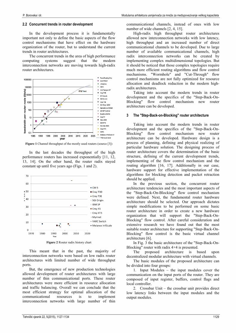
Figure 1 Channel throughput of the mostly used routers (source [3])
In the last decades the throughput of the high
performance routers has increased exponentially [11, 12, 13, 14]. On the other hand, the router radix stayed constant up until five years ago (Figs. 1 and 2).
Figure 2 Router radix history chart
This meant that in the past, the majority of
interconnection networks were based on low radix router architectures with limited number of wide throughput ports.
But, the emergence of new production technologies allowed development of router architectures with large number of thin communicational ports. These router architectures were more efficient in resource allocation and traffic balancing. Overall we can conclude that the most efficient strategy for optimal allocation of the communicational resources is to implement interconnection networks with large number of thin
communicational channels, instead of ones with low number of wide channels [2, 4, 15].
High-radix high throughput router architectures allowed new interconnection networks with low latency, high throughput and an increased number of direct communicational channels to be developed. Due to large number of available communicational channels, high radix interconnection networks can be created by implementing complex multidimensional topologies. But it should be noticed that those complex topologies require much more efficient routing algorithms and flow control mechanisms. "Wormhole" and "Cut-Through" flow control mechanisms are not fully optimized for resource allocation and deadlock reduction in the modern high-radix architectures.
Taking into account the modern trends in router development and the specifics of the "Step-Back-On-Blocking" flow control mechanism new router architecture can be developed.
3 The "Step-Back-on-Blocking" router architecture
Taking into account the modern trends in router
development and the specifics of the "Step-Back-On-Blocking" flow control mechanism new router architecture can be developed. Hardware design is a process of planning, defining and physical realizing of particular hardware solution. The designing process of router architecture covers the determination of the basic structure, defining of the current development trends, implementing of the flow control mechanism and the routing algorithm [16, 17]. Additionally in our case, hardware support for effective implementation of the algorithms for blocking detection and packet retraction should be applied.
In the previous section, the concurrent router architecture tendencies and the most important aspects of the "Step-Back-On-Blocking" flow control mechanism were defined. Next, the fundamental router hardware architecture should be selected. Our approach dictates simple modifications to be performed on some basic router architecture in order to create a new hardware organization that will support the "Step-Back-On-Blocking" flow control. After careful consideration and extensive research we have found out that the most suitable router architecture for supporting "Step-Back-On-Blocking" flow control is the basic virtual channel architecture [6].
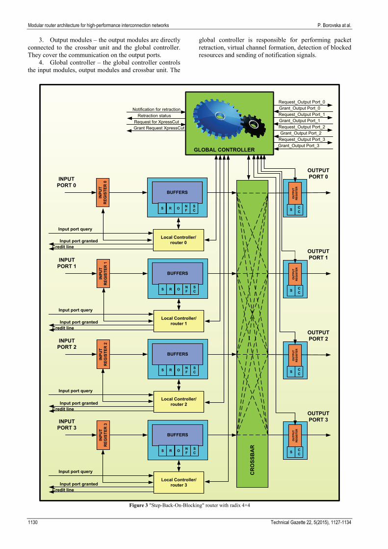
In Fig. 3 the basic architecture of the "Step-Back-On-Blocking" router with radix 4×4 is presented.
The proposed architecture is based upon decentralized modular architecture with virtual channels.
The basic modules of the proposed architecture can be divided into four groups:
1. Input Modules – the input modules cover the communication on the input ports of the router. They are composed of input register, buffers, control flags and local controller.
2. Crossbar Unit – the crossbar unit provides direct low latency links between the input modules and the output modules.
Modular router architecture for high-performance interconnection networks P. Borovska at al.
1130 Technical Gazette 22, 5(2015), 1127-1134
3. Output modules – the output modules are directly connected to the crossbar unit and the global controller. They cover the communication on the output ports.
4. Global controller – the global controller controls the input modules, output modules and crossbar unit. The
global controller is responsible for performing packet retraction, virtual channel formation, detection of blocked resources and sending of notification signals.
Figure 3 "Step-Back-On-Blocking" router with radix 4×4
INPUT PORT 0
Input port query
Input port granted
BUFFERS
Local Controller/router 0
INPU
T R
EGIS
TER
0
OUTPUT PORT 0
S R O NF
SC S C
C
INPUT PORT 1
Input port query
BUFFERS
Local Controller/router 1
INPU
T R
EGIS
TER
1
S R O NF
SC
CR
OSS
BA
R
INPUT PORT 2
Input port query
BUFFERS
Local Controller/router 2
INPU
T R
EGIS
TER
2
S R O NF
SC
OU
TPU
T R
EGIS
TER
INPUT PORT 3
Input port query
BUFFERS
Local Controller/router 3
INPU
T R
EGIS
TER
3
S R O NF
SC
OUTPUT PORT 1
S CC
OU
TPU
T R
EGIS
TER
OUTPUT PORT 2
S CC
OU
TPU
T R
EGIS
TER
OUTPUT PORT 3
S CC
OU
TPU
T R
EGIS
TER
Notification for retraction
Request for XpressCutRetraction status
Grant Request XpressCut
Request_Output Port_3
Request_Output Port_0
Request_Output Port_1
Request_Output Port_2
Grant_Output Port_0
Grant_Output Port_1
Grant_Output Port_2
Grant_Output Port_3GLOBAL CONTROLLER
Credit line
Input port grantedCredit line
Input port grantedCredit line
Input port grantedCredit line
P. Borovska i dr. Modularna arhitektura usmjerivača za mreže za međupovezivanje velikog kapaciteta
Tehnički vjesnik 22, 5(2015), 1127-1134 1131
3.1 Input modules of the "Step-Back-On-Blocking" router
The input modules are covering the communication on the input ports of the router. They are composed of input register, buffers, control flags and local controller.
The input register is used for temporary storing of the receiving flits. Using the input register, the routing information is extracted from the head flit. The routing information is immediately sent to the local and global controllers. Based on this information the global controller allocates the time usage of crossbar unit and the local controller sets the appropriate output pointers of the virtual channel.
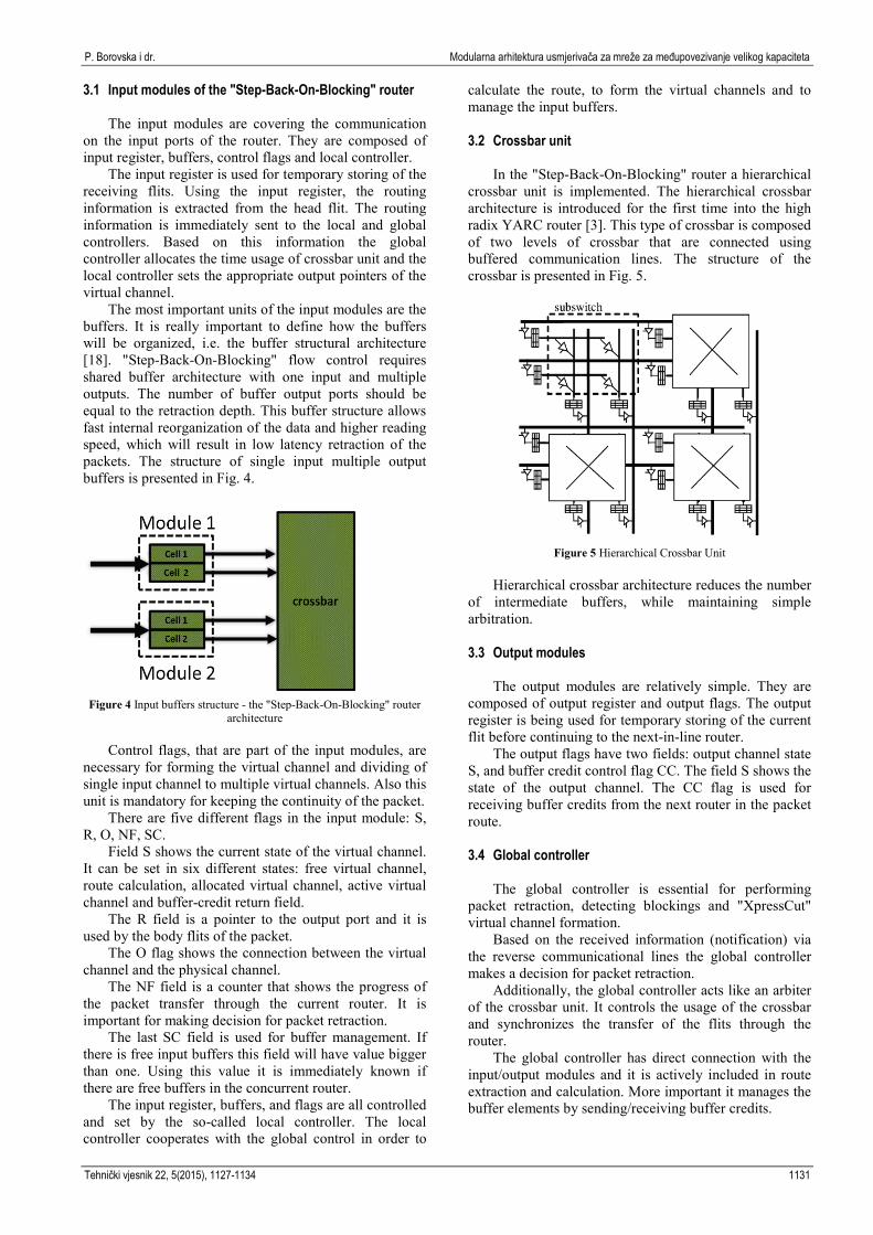
The most important units of the input modules are the buffers. It is really important to define how the buffers will be organized, i.e. the buffer structural architecture [18]. "Step-Back-On-Blocking" flow control requires shared buffer architecture with one input and multiple outputs. The number of buffer output ports should be equal to the retraction depth. This buffer structure allows fast internal reorganization of the data and higher reading speed, which will result in low latency retraction of the packets. The structure of single input multiple output buffers is presented in Fig. 4.
Figure 4 Input buffers structure - the "Step-Back-On-Blocking" router
architecture Control flags, that are part of the input modules, are
necessary for forming the virtual channel and dividing of single input channel to multiple virtual channels. Also this unit is mandatory for keeping the continuity of the packet.
There are five different flags in the input module: S, R, O, NF, SC.
Field S shows the current state of the virtual channel. It can be set in six different states: free virtual channel, route calculation, allocated virtual channel, active virtual channel and buffer-credit return field.
The R field is a pointer to the output port and it is used by the body flits of the packet.
The O flag shows the connection between the virtual channel and the physical channel.
The NF field is a counter that shows the progress of the packet transfer through the current router. It is important for making decision for packet retraction.
The last SC field is used for buffer management. If there is free input buffers this field will have value bigger than one. Using this value it is immediately known if there are free buffers in the concurrent router.
The input register, buffers, and flags are all controlled and set by the so-called local controller. The local controller cooperates with the global control in order to
calculate the route, to form the virtual channels and to manage the input buffers. 3.2 Crossbar unit
In the "Step-Back-On-Blocking" router a hierarchical crossbar unit is implemented. The hierarchical crossbar architecture is introduced for the first time into the high radix YARC router [3]. This type of crossbar is composed of two levels of crossbar that are connected using buffered communication lines. The structure of the crossbar is presented in Fig. 5.
Figure 5 Hierarchical Crossbar Unit
Hierarchical crossbar architecture reduces the number
of intermediate buffers, while maintaining simple arbitration. 3.3 Output modules
The output modules are relatively simple. They are
composed of output register and output flags. The output register is being used for temporary storing of the current flit before continuing to the next-in-line router.
The output flags have two fields: output channel state S, and buffer credit control flag CC. The field S shows the state of the output channel. The CC flag is used for receiving buffer credits from the next router in the packet route. 3.4 Global controller
The global controller is essential for performing packet retraction, detecting blockings and "XpressCut" virtual channel formation.
Based on the received information (notification) via the reverse communicational lines the global controller makes a decision for packet retraction.
Additionally, the global controller acts like an arbiter of the crossbar unit. It controls the usage of the crossbar and synchronizes the transfer of the flits through the router.
The global controller has direct connection with the input/output modules and it is actively included in route extraction and calculation. More important it manages the buffer elements by sending/receiving buffer credits.
Modular router architecture for high-performance interconnection networks P. Borovska at al.
1132 Technical Gazette 22, 5(2015), 1127-1134
4 Experimental performance evaluation
The communication performance evaluation of the proposed router architecture was performed on the basis of numerous simulation experiments conducted in the OMNeT++ discrete event simulation environment.
We have chosen the OMNeT++ simulator, because it offers tools for modelling and simulating wide variety networks and computing architectures. Some of its main advantages are: free to use for academic organizations; offers extensible, component-based simulation framework; provides user friendly Java Eclipse IDE, including TKEV; supports different operating systems like Windows and Linux; known to work with several C++ compilers; supports transparent parallel distributed simulation.
For communicational performance evaluation purposes flexible router simulation model was created. The simulation model is composed of capsulated modules. The router models are written as independent modules, which permits implementation of different flow control mechanisms. The basic components of the router simulation model are listed below: • Local_Input_Module – composed of Input_Reg,
Local_Controller, Flags, Buffers; • Global_Controller – composed of Routing_Logic,
Control_Lines, Crossbar_Arbiter; • Crossbar_Unit; • Local_Output_Module – composed of Output_Reg,
Flags; • Communication_Lines
The efficiency of the "Step-Back-On-Blocking"
router architecture has been verified by estimating the communicational performance of the interconnection networks, where it has been implemented, from a number of different aspects: maximal channel throughput, relation between the network latency and offered load, relation between the network latency and the packet retraction depth, internal router latency. Also a direct comparison between the "Step-back-on-blocking" router en routers supporting "Wormhole" and "Virtual Cut-Through" flow controls has been realized.
The experiments were conducted upon a simulation model of high performance interconnection network with 2D Mesh topology. The size of the network was predetermined at 10.000 computing nodes. The maximal channel throughput was defined at 1 Gbps.
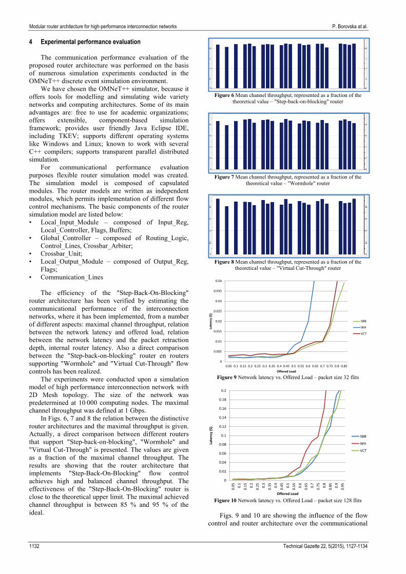
In Figs. 6, 7 and 8 the relation between the distinctive router architectures and the maximal throughput is given. Actually, a direct comparison between different routers that support "Step-back-on-blocking", "Wormhole" and "Virtual Cut-Through" is presented. The values are given as a fraction of the maximal channel throughput. The results are showing that the router architecture that implements "Step-Back-On-Blocking" flow control achieves high and balanced channel throughput. The effectiveness of the "Step-Back-On-Blocking" router is close to the theoretical upper limit. The maximal achieved channel throughput is between 85 % and 95 % of the ideal.
Figure 6 Mean channel throughput, represented as a fraction of the
theoretical value – "Step-back-on-blocking" router
Figure 7 Mean channel throughput, represented as a fraction of the
theoretical value – "Wormhole" router
Figure 8 Mean channel throughput, represented as a fraction of the
theoretical value – "Virtual Cut-Through" router
Figure 9 Network latency vs. Offered Load – packet size 32 flits
Figure 10 Network latency vs. Offered Load – packet size 128 flits
Figs. 9 and 10 are showing the influence of the flow
control and router architecture over the communicational
0
0.005
0.01
0.015
0.02
0.025
0.03
0.035
0.04
0.05 0.1 0.15 0.2 0.25 0.3 0.35 0.4 0.45 0.5 0.55 0.6 0.65 0.7 0.75 0.8 0.85
Late
ncy
(S)
Offered Load
SBB
WH
VCT
0
0.02
0.04
0.06
0.08
0.1
0.12
0.14
0.16
0.18
0.2
0.05 0.
10.
15 0.2
0.25 0.
30.
35 0.4
0.45 0.
50.
55 0.6
0.65 0.
70.
75 0.8
0.85 0.
90.
95
Late
ncy
(S)
Offered Load
SBB
WH
VCT
P. Borovska i dr. Modularna arhitektura usmjerivača za mreže za međupovezivanje velikog kapaciteta
Tehnički vjesnik 22, 5(2015), 1127-1134 1133
performance of an interconnection network. Actually, the figures are exhibiting the relation of the latency to the offered load in interconnection network when packets with size of 32 and 128 flits are applied
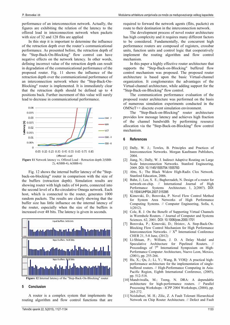
In this step it is important to determine the influence of the retraction depth over the router’s communicational performance. As presented before, the retraction depth of the "Step-Back-On-Blocking" flow control can have negative effects on the network latency. In other words, defining incorrect value of the retraction depth can result in degradation of the communicational performance of the proposed router. Fig. 11 shows the influence of the retraction depth over the communicational performance of an interconnection network where the "Step-Back-On-Blocking" router is implemented. It is immediately clear that the retraction depth should be defined up to 4 positions back. Further increment of this value will surely lead to decrease in communicational performance.
Figure 11 Network latency vs. Offered Load – Retraction depth 2(SBB-2), 4(SBB-4), 6(SBB-6)
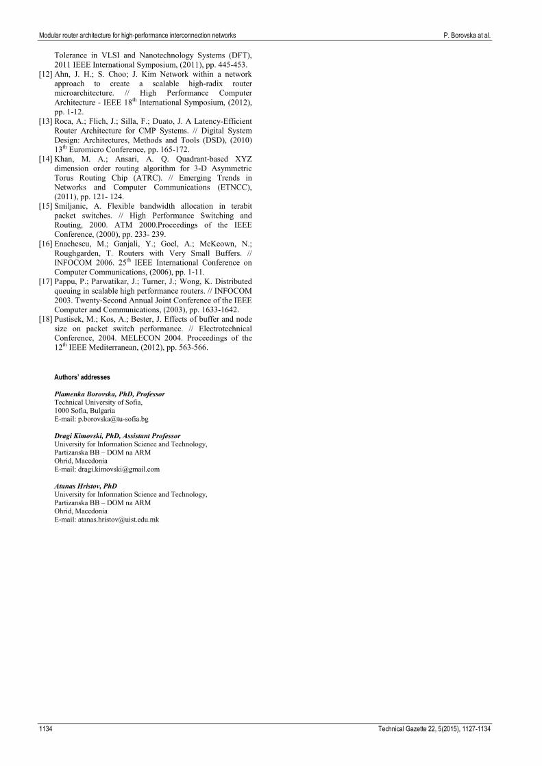
Fig. 12 shows the internal buffer latency of the "Step-
back-on-blocking" router in comparison with the size of the buffers (retraction depth). Simulation results are showing router with high radix of 64 ports, connected into the second level of a Re-circulative Omega network. Each host, which is connected to the router, generates 1000 random packets. The results are clearly showing that the buffer size has little influence on the internal latency of the router, especially when the size of the buffers is increased over 48 bits. The latency is given in seconds.
Figure 12 Internal latency of the "Step-Back-On-Blocking" router
5 Conclusion
A router is a complex system that implements the routing algorithm and flow control functions that are
required to forward the network agents (flits, packets) en route to their destination in the interconnection network.
The development process of novel router architecture has high complexity and it requires many different factors to be considered. Fundamentally, the concurrent high performance routers are composed of registers, crossbar units, function units and control logic that cooperatively implement the routing algorithm and flow control mechanism.
In this paper a highly effective router architecture that supports the "Step-Back-on-Blocking" buffered flow control mechanism was proposed. The proposed router architecture is based upon the basic Virtual-channel organization. It conglomerates the advantages of the Virtual-channel architecture, while adding support for the "Step-Back-on-Blocking" flow control.
The communication performance evaluation of the proposed router architecture was performed on the basis of numerous simulation experiments conducted in the OMNeT++ discrete event simulation environment.
The "Step-Back-on-Blocking" router architecture provides low message latency and achieves high fraction of the channel bandwidth by performing resource allocation via the "Step-Back-on-Blocking" flow control mechanism.
6 References [1] Dally, W. J.; Towles, B. Principles and Practices of
Interconnection Networks. Morgan Kaufmann Publishers, 2004.
[2] Jiang, N.; Dally, W. J. Indirect Adaptive Routing on Large Scale Interconnection Networks. Stanford Engineering, 2009. DOI: 10.1145/1555754.1555783
[3] Abts, S.; The Black Widow High-Radix Clos Network. Stanford Education, 2006.
[4] Bahn, J.; Lee, S. E.; Bagherzadeh, N. Design of a router for network-on-chip. // International Journal of High Performance Systems Architecture. 1, 2(2007). DOI: 10.1504/IJHPSA.2007.015395
[5] Kimovski, D.; Borovska, P. Novel Flow Control Method for System Area Networks of High Performance Computing Systems. // Computer Engineering, Sofia, 6, 1(2012).
[6] Cole, R. J. On the Benefit of Supporting Virtual Channels in Wormhole Routers. // Journal of Computer and Systems Sciences. 62, 2001. DOI: 10.1006/jcss.2000.1701
[7] Borovska, P.; Kimovski, D.; Hristov, A. Step-Back-On-Blocking Flow Control Mechanism for High Performance Interconnection Networks. // Xth International Conference CHER 21, 5-8 June, (2012)
[8] Li-Shiuan, P.; William, J. D. A Delay Model and Speculative Architecture for Pipelined Routers. // Proceedings of 7th International Symposium on High-Performance Computer Architecture, Nuevo Leon, Mexico, (2001), pp. 255-266.
[9] Hu, X.; Qu, J.; Li, Y.; Wang, B. VOIQ: A practical high-performance architecture for the implementation of single-buffered routers. // High-Performance Computing in Asia-Pacific Region, Eighth International Conference, (2005), pp. 512-518.
[10] Mandviwalla, M.; Tzeng, N. DRA: A dependable architecture for high-performance routers. // Parallel Processing Workshops - ICPP 2004 Workshops, (2004), pp. 265-272.
[11] Neishaburi, M. H.; Zilic, Z. A Fault Tolerant Hierarchical Network on Chip Router Architecture. // Defect and Fault
Modular router architecture for high-performance interconnection networks P. Borovska at al.
1134 Technical Gazette 22, 5(2015), 1127-1134
Tolerance in VLSI and Nanotechnology Systems (DFT), 2011 IEEE International Symposium, (2011), pp. 445-453.
[12] Ahn, J. H.; S. Choo; J. Kim Network within a network approach to create a scalable high-radix router microarchitecture. // High Performance Computer Architecture - IEEE 18th International Symposium, (2012), pp. 1-12.
[13] Roca, A.; Flich, J.; Silla, F.; Duato, J. A Latency-Efficient Router Architecture for CMP Systems. // Digital System Design: Architectures, Methods and Tools (DSD), (2010) 13th Euromicro Conference, pp. 165-172.
[14] Khan, M. A.; Ansari, A. Q. Quadrant-based XYZ dimension order routing algorithm for 3-D Asymmetric Torus Routing Chip (ATRC). // Emerging Trends in Networks and Computer Communications (ETNCC), (2011), pp. 121- 124.
[15] Smiljanic, A. Flexible bandwidth allocation in terabit packet switches. // High Performance Switching and Routing, 2000. ATM 2000.Proceedings of the IEEE Conference, (2000), pp. 233- 239.
[16] Enachescu, M.; Ganjali, Y.; Goel, A.; McKeown, N.; Roughgarden, T. Routers with Very Small Buffers. // INFOCOM 2006. 25th IEEE International Conference on Computer Communications, (2006), pp. 1-11.
[17] Pappu, P.; Parwatikar, J.; Turner, J.; Wong, K. Distributed queuing in scalable high performance routers. // INFOCOM 2003. Twenty-Second Annual Joint Conference of the IEEE Computer and Communications, (2003), pp. 1633-1642.
[18] Pustisek, M.; Kos, A.; Bester, J. Effects of buffer and node size on packet switch performance. // Electrotechnical Conference, 2004. MELECON 2004. Proceedings of the 12th IEEE Mediterranean, (2012), pp. 563-566.
Authors’ addresses Plamenka Borovska, PhD, Professor Technical University of Sofia, 1000 Sofia, Bulgaria E-mail: [email protected] Dragi Kimovski, PhD, Assistant Professor University for Information Science and Technology, Partizanska BB – DOM na ARM Ohrid, Macedonia E-mail: [email protected] Atanas Hristov, PhD University for Information Science and Technology, Partizanska BB – DOM na ARM Ohrid, Macedonia E-mail: [email protected]