Embed Size (px)
Citation preview
3930 Enterprise Drive
Janesville, WI 53546
P.O. Box 67
Milton, Wisconsin 53563
Phone 608/314-1620
Fax 608/314-1625
www.janesvilletool.com
12/17
Model P-8151 1 Stage 4—1/2” Bore x 3” Stroke-Double End 601
Repair Kit 4—1/2” Bore Double End—1 Stage 20352
Model P-8302 2 Stage 4—1/2” Bore x 3" Stroke Double End 617
Repair Kit 4—1/2” Bore Double End—2 Stage 617-RK
Model P-8453 3 Stage 4—1/2” Bore x 3" Stroke Double End 619
Repair Kit 4—1/2” Bore Double End—3 Stage 619-RK
3930 Enterprise Drive
Janesville, WI 53546
P.O. Box 67
Milton, Wisconsin 53563
Phone 608/314-1620
Fax 608/314-1625
www.janesvilletool.com
P-8000 SERIES
P-8151
P-8302
P-8453
USER NAME# 4711
SERIAL#_________
Cylinder Information
8
Unpacking and Setup
For shipping purposes, the HMI screen and Banner Opto-Touch® buttons are positioned so that shipping damage is
minimized. Locate the set screws at the mounting brackets and loosen with an Allen wrench. Position the HMI screen
and the Banner Opto-Touch® buttons to the desired position and tighten set screws for the press operation.
Power Cord is located inside the main control box. The receptacle for the power cord is located on the left side of the
press on the main control box.
Mo
del
P-8
151
, P
-83
02,
P-8
45
3
2 7
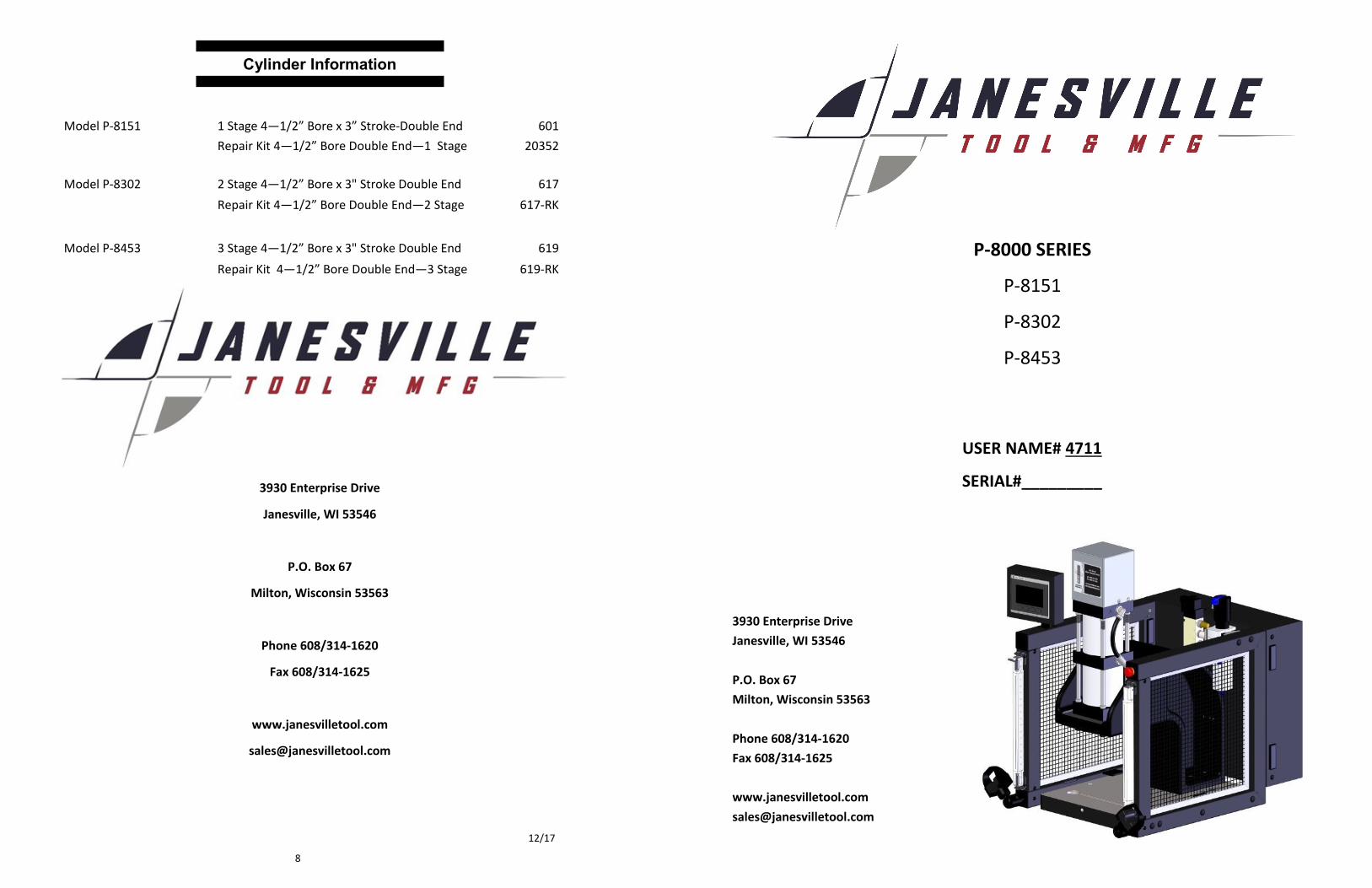
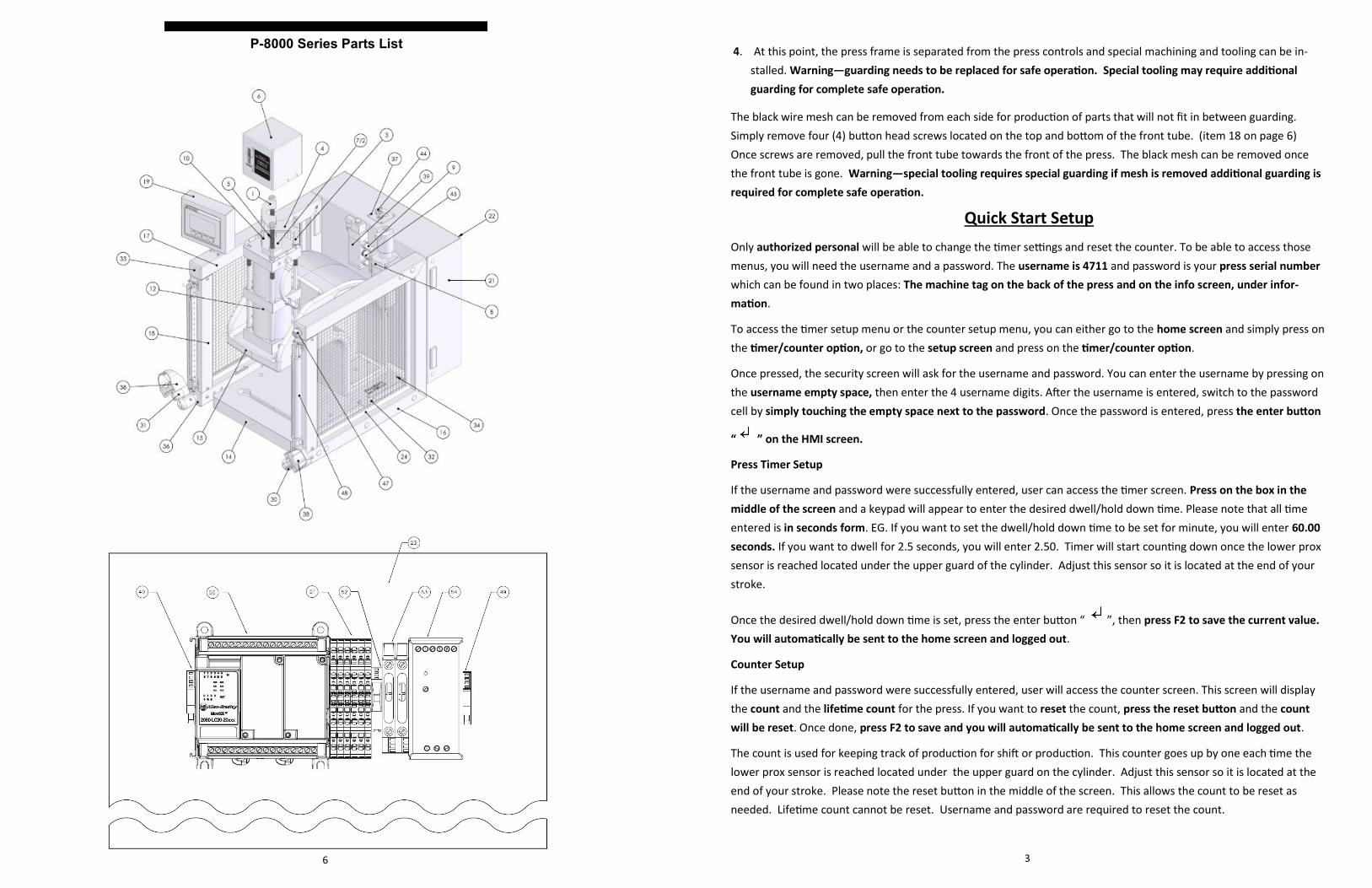
ITEM NO. PART NUMBER DESCRIPTION QTY.
1 1465-85 4 1/2" PROX MOUNT 2
2 3000-07 STOP PLATE FOR 601/U & 617/U 1
3 3000-08 ANTI-ROTATE STUD 1
4 3000-10 ANTI-ROTATE PLATE 1
5 3000-27 THREADED ROD 2
6 3000-35 TOP GUARD 1
7 4000-30 H. D. STOP PLATE MULTI STG. 619/U & 621/U 1
8 544 FILTER REGULATOR 1
9 547 1/2" NPT MUFFLER 2
10 570C PROX SENSOR 2
11 601/U 4 1/2" SINGLE STAGE CYLINDER 1
12 617/U 4 1/2" 2 STAGE CYLINDER 1
13 619/U 4 1/2" 3 STAGE CYLINDER 1
14 8000-07 8000 BASE 1
15 8000-11 8000 FRAME 1
16 8000-15 RIGHT SIDE LEG 1
17 8000-16 LEFT SIDE LEG 1
18 8000-17 FRONT TUBE 2
19 8000-18 SMALL CONTROL BOX 1
20 8000-19 SMALL BACK PANEL 1
21 8000-20 LARGE CONTROL BOX 1
22 8000-21 LARGE BACK PANEL 1
23 8000-22 INNER PANEL 1
24 8000-23 8020 PANEL STIFFENER-17 6
25 8000-24 8020 PANEL STIFFENER-16 2
26 8000-25 AIR KNUCKLE 1
27 8000-26 ASSEMBLY BUSHING 4
28 8000-27 BOTTOM MONITOR MOUNT 1
29 8000-28 TOP MONITOR MOUNT 1
30 8000-29 LOCKING ARM CAP 2
31 8000-30 ARM NUT 2
32 8000-32 8000 MOUNTING BRACKET 2
33 8000-34 SQUARE PLUG 1
34 8000-35 BLACK WIRE MESH 2
35 8000-39 ARM 2
36 8000-40 ARM SUPPORT CAP 2
37 8000-41 QUICK DISCONNECT PLATE 1
38 906 OPTO 24V ASSEMBLY 2
39 908 VALVE 1
40 914 POWER CORD 6' 1
41 915 IEC CONNECTOR 1
42 919 BRASS BARBED ELBOW 1
43 920 ZINC PLATED BARBED HOSE FITTING 1
44 921 MALE PLUG 1
45 927 STAINLESS STEEL PIPE NIPPLE 2.50 LG 1
46 930 LED 24V FLEXIBLE LIGHT 1
47 931 E-STOP-OPTIONAL 1
48 SLV-420H LIGHT CURTAIN-OPTIONAL 1
49 910 END BLOCK 2
50 902 PLC 1
51 911 TERMINAL BLOCK 6
52 904 GROUND TERMINAL BLOCK 1
53 903 FUSE HOLDER 1
54 905 POWER SUPPLY 1
Safety Instructions
DO NOT OPERATE PRESS WITH GUARDS REMOVED.
ALL SAFETY DEVICES MUST BE INSTALLED AND OPERABLE.
ADDITIONAL GUARDING IS REQUIRED FOR SPECIAL TOOLING.
DISCONNECT PRESS when not in use, before servicing, and when changing accessories, such as down stops and tool-
ing.
WEAR SAFETY GLASSES WHILE OPERATING PRESS.
GUARD AGAINST ELECTRIC SHOCK. Do not use in damp locations.
DRESS PROPERLY. Do not wear loose fitting clothing or jewelry that could get caught in moving parts.
KEEP HANDS AWAY. Never reach near moving parts.
DO NOT OPERATE PRESS OVER 80 PSI. Excess pressure may cause damage or injury.
DO NOT OPERATE PRESS OVER LABELED VOLTAGE.
WATCH FOR DAMAGED PARTS. If press is damaged during operation, examine the damaged part carefully to ensure
that it will operate properly. If in doubt, replace the damaged part. Check for alignment of moving parts, binding of
moving parts, mounting and any other conditions that may affect its operation.
KEEP WORK AREA CLEAN. Cluttered areas and benches invite injuries.
STAY ALERT. Watch what you are doing. Use common sense.
FLOW CONTROLS – To alter the ram descent speed on you JT&M Press, adjust the screw marked B located on the
valve at the rear of the press. To alter the ram ascent speed, adjust screw A. (The ram retraction speed has been pre-
set by the factory.) Rotate the screws clockwise to decrease the speed of the ram.
PRESS OPERATION – To operate press, push palm buttons in at the same time. Hold the palm buttons in until the
down stroke is completed.
To Remove Press from Guarding for Special Tooling
1. Remove four (4) button head screws located on the base of the press.
2. Remove the quick disconnect connector located on top of the main control box. Item #54 on parts drawing page 6.
3. Remove the air lines from the cylinder at ports “A” and “B”. These fittings are push to fit fittings and require the
outer ring of the fitting to be pushed in as you pull the black flexible tube away from the fitting.
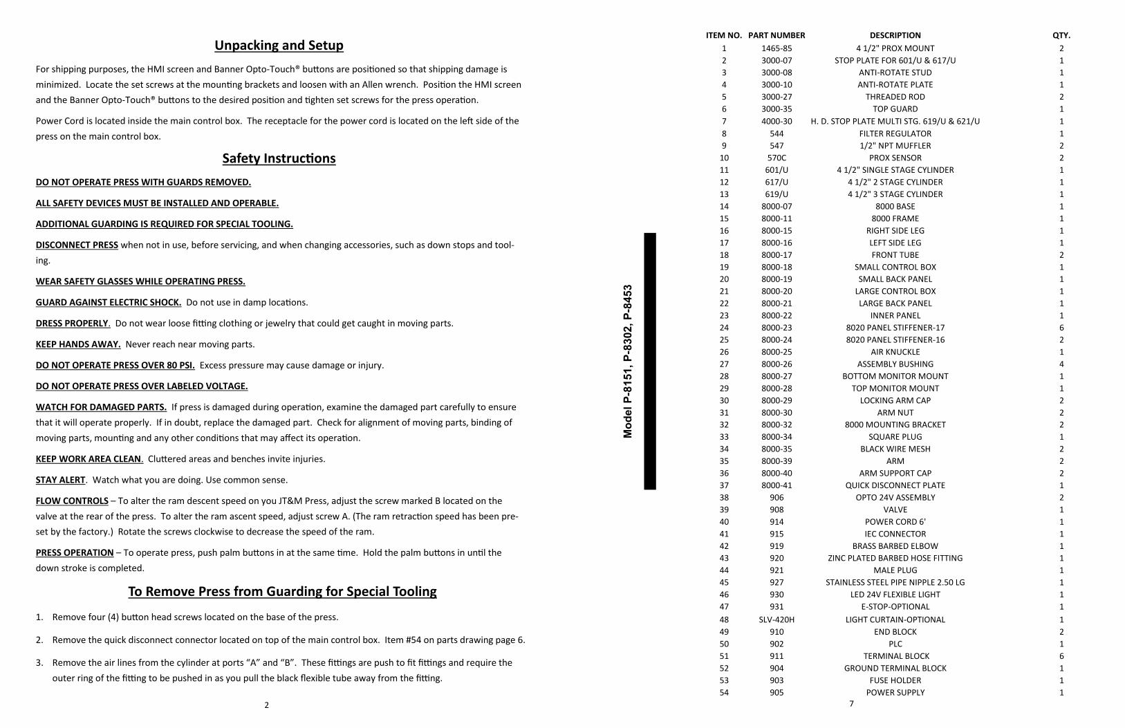
Electrical Schematic
4 5
Pneumatic Schematic
4. At this point, the press frame is separated from the press controls and special machining and tooling can be in-
stalled. Warning—guarding needs to be replaced for safe operation. Special tooling may require additional
guarding for complete safe operation.
The black wire mesh can be removed from each side for production of parts that will not fit in between guarding.
Simply remove four (4) button head screws located on the top and bottom of the front tube. (item 18 on page 6)
Once screws are removed, pull the front tube towards the front of the press. The black mesh can be removed once
the front tube is gone. Warning—special tooling requires special guarding if mesh is removed additional guarding is
required for complete safe operation.
3
Quick Start Setup
Only authorized personal will be able to change the timer settings and reset the counter. To be able to access those
menus, you will need the username and a password. The username is 4711 and password is your press serial number
which can be found in two places: The machine tag on the back of the press and on the info screen, under infor-
mation.
To access the timer setup menu or the counter setup menu, you can either go to the home screen and simply press on
the timer/counter option, or go to the setup screen and press on the timer/counter option.
Once pressed, the security screen will ask for the username and password. You can enter the username by pressing on
the username empty space, then enter the 4 username digits. After the username is entered, switch to the password
cell by simply touching the empty space next to the password. Once the password is entered, press the enter button
“ ” on the HMI screen.
Press Timer Setup
If the username and password were successfully entered, user can access the timer screen. Press on the box in the
middle of the screen and a keypad will appear to enter the desired dwell/hold down time. Please note that all time
entered is in seconds form. EG. If you want to set the dwell/hold down time to be set for minute, you will enter 60.00
seconds. If you want to dwell for 2.5 seconds, you will enter 2.50. Timer will start counting down once the lower prox
sensor is reached located under the upper guard of the cylinder. Adjust this sensor so it is located at the end of your
stroke.
Once the desired dwell/hold down time is set, press the enter button “ ”, then press F2 to save the current value.
You will automatically be sent to the home screen and logged out.
Counter Setup
If the username and password were successfully entered, user will access the counter screen. This screen will display
the count and the lifetime count for the press. If you want to reset the count, press the reset button and the count
will be reset. Once done, press F2 to save and you will automatically be sent to the home screen and logged out.
The count is used for keeping track of production for shift or production. This counter goes up by one each time the
lower prox sensor is reached located under the upper guard on the cylinder. Adjust this sensor so it is located at the
end of your stroke. Please note the reset button in the middle of the screen. This allows the count to be reset as
needed. Lifetime count cannot be reset. Username and password are required to reset the count.
P-8000 Series Parts List
6


![STRATISS - CVE-2018-8453 - Sanitized...LookingGlass STRATISS: Confidential | 2 CVE-2018-8453 Being Sold on Exploit[.]in On December 6, 2018, Russian threat actor X advertised the sale](https://img.dokumen.tips/doc/110x75/5f6498cbf1e0d45aa74d7626/stratiss-cve-2018-8453-sanitized-lookingglass-stratiss-confidential-2.jpg)