Embed Size (px)
Citation preview

I
I
NASA-CR-192017_J
V3_"
f-
p_ _ 5
I
|
|
AEI_OSPACE FIINAL DESIGIN _EFO..R.T
1991-92
|
NASA/USRA Design Project: Extended 1VIission/Lv._--"r .._.over
|FAMU/FSU College of Engineering
Aerospace Design Program
Executive Summary
(NASA-CR-192017) EXTENDED
MISSIQN/LLINAR ROVER, EXECUTIVE
SU_!MARY Final Oesi_n Report, 1991
1992 (Florid_ Agricultural and
Mechanical llniv.) 25 O
G3/37
N93-18162
Unclas
0141645
https://ntrs.nasa.gov/search.jsp?R=19930008973 2018-05-24T07:51:58+00:00Z

|
Ii
|
II
|
Ii
|
|
|
!
!
|
I!
I!
|
t
!
I
Table of Contents
List of Figures
1. IINTRODUCTION
1.1 Project Management and Organization
2. MISSION STATEMENT AND REQUIREMENTS
2.1 Mission Scenarios
3. SYSTEM DESIGN AND INTEGRATION
3.1 Transportability
3.2 Suspension
3.3 Radiation Shielding
3.4 Airlock
3.5 Vehicle Shell
4. AVIONICS
4.1 Workstation
4.2 Input and Output Devices
4.3 Communication
4.4 Link Performances and Antenna Types
4.5 Navigation
4.6 Heads Up Display
4.7 Robotic Arms
4.8 Electronically Scanned Laser Pathfinder
4.9 Moving Map Display Processor for finding LC P_th
5. THERMAL�FLUID
5.1 Environmental Requirements
5.2 Waste Removal and Storage
5.3 Water Supply
5.4 Cryogenic Storage
5.5 Leak Containment
5.6 Airlock Management
5.7 Fire Suppression
6. POWER GENERATION
6.1 Radioisotope Generators
6.2 :Fuel Capsules
6.3 Overall Design
6.3.1 Radiator Design
6.4 Future Considerations
2
2
5
,¢t
8
8
9
9
9
].O
].].
1.].
].].
].2
.1.2
].8
1d
lzl
1A
]5
].5
15
-1.5
.1.7
].7
]7
.18
].8
.1.8
]..o

6.5 Backup Power6.6 Propulsion System
6.6.1 Motor6.6.2 Power Control Methods6.6.3 Tachometers
7. Impact of NASA/USRA on University, Faculty _%5tu.ct__n_
.1.9!.9192.92.922
ii

List of Figures
1.1
2.1
3.1
4.1
5.1
6.1
Class organization
Side view of vehicle
Primary and secondary suspension
Communication network
Water supply and waste removal schematic
Power requirements for lunar rover
2
7
ID
13
16
20
iii

1. IrqTRODUCTION
A key component in ensuring America's status asa leader in the _,:,b_l communit,v is its
active pursuit of Space Exploration. On the twentieth anniversary of Apollo 11 President Bush
challenged our nation to permanently place a man on the moon and event,_ally conduct human
exploration of Mars in the twenty-first century. The name for this challenge is America's Space
Exploration Initiative (SEI) and the students of the FAMU/FSU College of Engineering hope
to make a significant contribution to the SEI with their participation in the NASA/'USRA
Advanced Design Program.
The design project selected to be undertaken by the 1991/92 Aeroseace Design Group
was that of conceptually designing an Extended Mission Rover for use ez the Lunar Surface.
This vehicle would serve the function as a mobile base of sorts, and be able to provide
future astronauts with a mobile "shirt-sleeve" self-sufficient living and working environment.
Some of the proposed missions would be planetary surface exploration, construction and
maintenance, hardware set-up and in-situ resource experimentation. The need for this type
of vehicle has already been declared in the Stafford Group's report on the future of America's
Space Program, entitled "America at the Threshold: America's Space Exploration Initiative".
In the four architectures described within the report, the concept of a pressurized vehicle
occurred multiple times. The approximate time frame that this vehicle would be put into use
is 2010-2030.
il
t
|
Ii
1
|
B
1
1.1 Project Management and Organization
The overall organization of the 199t/92 Senior Aerospace Design class was conducted in
a matrix management fashion. All of the students involved in the project were assigned to
a Design Group and a Management group. By doing this it provided the students with a
true feeling for how projects are organized in the industrial sector. The class consisted of
seven mechanical engineering students and nine electrical engineering st,._dents. Due to the
diverse make-up of the class, students were often involved in interdiscip, linary tasks in the
project. The overall organization of the class can be seen in Fig. 1.1. The upper level of
project management consisted of a NASA/USRA interface along xx-ith a team of three faculty
advisors. The class met twice a week, one day being reserved for guest !ecturers on various
aerospace related topics and the other day being reserved for work on the design project. At
the class level a project manager was selected by the Faculty Board of Advisors through an
interview process held at the end of the Spring 1991 semester. At the o,_set of the Fail 1991
semester a Deputy Project Manager was assigned. The function of the Deputy P.M. was to
assist the P.M. in various organizational and interface duties. Also an Executive Systems
Engineer was appointed at the start of the project. The main function of the Executive
Systems Engineer was to oversee and predict possible integration conflicts between the design
_oups.
PRECEDING P;._Cli- _''_.7,t,- _:.LA, oK NOT F!LMED

iList of Student Participants
Manh Chung: Reference Control, S.D.&:I., MRWG
• Ken Clarke: Report Integration, S.D.&I., MRWG
• Kevin Frankle: Reference Control, S.D.&I.
• Anthony Halecki: Project Manager, S.D.&I'.
• Fariba Kassemkhani: Report Integration, Avionics
• John Kuhlhoff: Report Integration, ThermM/Fluid', MRWG
* Josh Lenzini: Reference Control, Power Generation"
• David Lobdell: Project Control, S.D.&I., MRWG
|
|
1
|
tl
|
!
!
]
!
* Sam Morgan: Visual Display, Fluids
. Robert Nock: Project Control, S.D.&I., MRWG
• Sabash Panigsahi: Visual Display, S.D.&I.
• Cynthia Robbins: Report Integration, S.D.&I.
• Mark Russell: Visual Display, S.D.&I.
* Rowi Shah: Visual Display, Avionics"
• Gail Wallace: Chief Systems Engineer, Project Control'_ ThermalFluid
• Russell Willis: Report Integration', Power Generation, MR\VG
• * - Team leader.
Figure 1.1. Class organization.
3

Ii
Ii
II
IN
IN
il
IN
IN
IN
!
1
I
11
!
!
The management teams organized for this project ,.'ere the following: Project Control.
Report Integration, Visual Display and Reference Control. The duties of the Project Control
team included publication and distribution Bof weekly progress reports and agendas, overall
project scheduling, requisitioning of needed supplies and equipment, ap_d financial bookkeep-
ing. The duties of the Report Integration team included the estabiishment of the format
and outline of the final and midterm reports, mandating the acceptable graphics formats
and layouts to be used in the report, and management and control of the Aerospace Design
Account on the College of Engineering's VAX mainframe. The duties of the Visual Display
team included the selection of the type of model to be displayed at the _qummer USRA con-
ference (multi-media or physical), production of any necessary visual 4_isp.lay aides needed
for the intermediary and final design reviews, and production of any t_e,_essary artwork for
the report. The duties of the Reference Control team included upkeep and management of
the Aerospace Reference Library, procurement of any additional necessary reference material,
and interfacing with industry contacts.
The design teams organized for this project were the following: 53sten) Design and Inte-
gration, Avionics, Power Generation, and Thermal/Fluid. The duties er the System Design
and Integration team included the design of the vehicle shell and supporting structures, se-
lection/design of wheels and suspension system, identification of necess._ry redundant and
emergency subsystems, logistics planning and support, basic maintanePce scheduling, de-
sign/selection of air/man-lock, interior vehicle layout and supporting CAD dra_vings, and
mass and volume budgeting. The duties of the Avionics team included ,Jesign/'selection of
the necessary guidance and navigation systems, communications system.data acquisition and
storage systems, design of necessary workstations and data managemevt, and exterior en-
x-ironment imaging systems. The duties of the Power Generation team included selection
and sizing of the appropriate fuel cell/system for vehicle support and lec,:motion, radiation
shielding, and internal environmental control systems. The duties of _he Thermal/Fluid
Group included design/selection of proper fluid storage devices, critical fluid estimates and
budgeting, pumping systems, hydraulics, fire suppression systems, and design, selection of the
llfe-support and waste management systems.
I
1
I4

2. MISSION STATEMENT AND REQUI..IREMENT$
The purpose of the design for an extended mission rover w,-,dd b "_ tr, pr_,vid ,_ trans-
portation, shelter and working quarters for a crew of four on long d,_,r_ion l,.mar surface
missions. To effectively fulfill this purpose a stand-alone temporary rec_,.,Jrements group was
formed. This group researched the proposed requirements submitted _d .__ugg,_ted._ .... by the
entire design class at a preliminary round-table meeting. By researchin, exisiing technolo-
gies and forecasts of available future technologies, the _V_ssion Requiremevts Working Group
reformulated the proposed requirements and restrictions into a collaber__tion of viable ex-
pectations. The preliminary mission requirements, as defined by the _[Jssi,_m Requirements
Working Group, (MRWG) are as follows:
• Mission Distance: 1000 km round trip
° Mission Duration: 28 Earth Days (1 Lunar Day)
• Support Crew and Cargo (Oxygen, food, water, climate)
• Maximum Crew Size: 4
• Self-sufficient environment
• Maintain interior environment during egress
° Transport various experimental apparatus
° Possess robotic data sample/data collection capability
• Collect/analyze/store data
° Communication capability with base and earth
° Provide shielding from environmental elements
• Internal navigational support
° Unmanned capability
• Possess path-clearing abilities
• Travel over rough terrain (45 ° head-on, 20 ° traverse)
Provide redundant systems
ORIGINAL P_C_z7 I_OF POOR QO._,L[,,'rv

Easily maintained
_i'rhe list of requirements formulated by the MI:{WG were deemed acceptable and realisiic
_ _the entire Aerospace Design Class, and were used as the basis upoa which te begin the
_la_ptuM design of the vehicle. Further justification for the acceptance ef the crew size and
__..----i_t_l traverse distance was found in the Pressurized Manned Rover !_.e,_l,_,.irements for long
vehicles. By keeping the expected traverse distance under 3000 km for a time period
proximately one month the size of the fuel cell tankage was kept smM1 enough so that
not become detrimental to the accomplishment of the stated missien objectives. The
of reformulation of the requirements was left open, with the stipul._,tion of the approvM
project manger and chief systems engineer.
-2.1 Mission Scenarios
multi-purpose nature of the vehicle design makes it flexible eae,_,.gh for use in many
applications. One such application would be that of extensive surface exp oration Although
the lunar surface can be mapped with an orbiting satellite imaging _v_tom_.., the resolution
of detail available from existing systems leaves something to be desired. By being able to
venture great distances from the base, the vehicle allows firsthand observ.ati.en and assessment
of the terrain _'ithin a 500 km radius of the base. Extensive geologice_l exeerimentation of sites
located a great distance from the base could also be accomplished by , .tilJ.z_tion of the vehicle.
Lengthy analysis and assessment of possible valuable mineral depesits __e,,1O be conducted
while the astronauts were habitating the vehicle. Also, set-up of s,_tcb se_.sitive hardware as
space radio telescopes could be done at a great enough distance from _he permanent base%
lander site so as not to cause interference from vibrations caused by the lender's engines.
The capability of the vehicle to allow the realization of such scenaries _s fbe aforementioned
justifies the need for its design mad eventual production. A side view ef_he vehicle can be
seen in Fig. 2.1.
OF POC'.R Q,9,-L! :_,_i

,5,
Figure 2.1. Side view of vehicle.
7
_J _,k _I__OF POOR _ ....._

3. SYSTEM DESIGN AND I1NTEGRATIOI'V
mrtability
design of the EMR was based upon the forecast of future technologies consistent with
Lded within available references. Rough calculations were also carried out to ensure
with these predictions. Rather than trying to carry out det_iied calculations
portation system, the approach was to ensure that the mass _Jqd size of the EMIR
exceed the limitations predicted by the available references.
the report released by Boeing Defense and Space Group. :\.dv._nced Civil Space
in Huntsville, Alabama a launch vehicle and lander system w.as {bund that would
accomodate the EMR. The estimated payload delivered to the lun_.r surface was 45rot.
was based on the concept of delivering a fully integrated habit.at _e the lunar surface.
would fit into Boeing's LTV tandem stage expendable mode ,1sing the Direct, Lunar
___Orbit Rendezvous (LOR) high-thrust profile. The launch vehicle proposed, b3 Boeing ,,as in
._'T_tlle range of 100-400rot _-ith a payload shroud of 10m diameter by ?0m Ien_fh. The suggested
_:_:_.':_<_y to carry the cargo would be to hang it on the underside of the Lander. If the payload is
_i>)i{.t9_ be underslung on the lander, some deployment or assembly may be needed on orbit if the
....Z._._.:_):: diameter limit of the launch vehicle is less than 10m. The reason for ?,rop, esing the idea of
_:-an underslung cargo is the inherent ease of unloading once the vehicle ta__s reached the lunar
" -tace.
_ 8.2
g:-It*
Suspension
The rough terrain of the Lunar surface represents great difl:iculties rot the locomotion
system of a ground based vehicle. Mobility requirements for a lunar b__se4 vehicle are very
diverse. Mission requirements vary greatly and the environment of locomoti'.-u may be literally
anywhere on the moon. To best meet these diverse needs, all practical mot:iljtv concepts were
examined. The different types of mobility concepts examined were: Tr.acked vehicles, walkers.and wheels,
Wheels will be the preferred mobility, option for many. missions. \\t_1_. _. _.... m_o__h_m_.aIlv
efficient, they can be designed into lightweight systems, and can be b,,}l_ _-i_b excellent
reliability. One problem with wheels in terrestrial ali-terrain appIicati,-,_ is that the, tend
to have a small footprint. In the reduced gravity field of the mo,:_, t_-,-i,g _ l__rge ground
contact area is not required.
The ELV will make use of six cone-shaped carbon graphite wheels _-_i_ _ s,.,i*able Nameter
of 72 inches and a thickness of 0.5 inches. The tread xridth will be 20 i-<!_es which _xqlt _ve
maximum traction which will help prevent slippage on the lunar surface. Tt_is -,vheot _x-ill _xo
an estimated minimum ground clearance of 38 inches. The overal] '::ei._>' r,,r _i:: c,_ne wheels
will be approximately 624 kg.
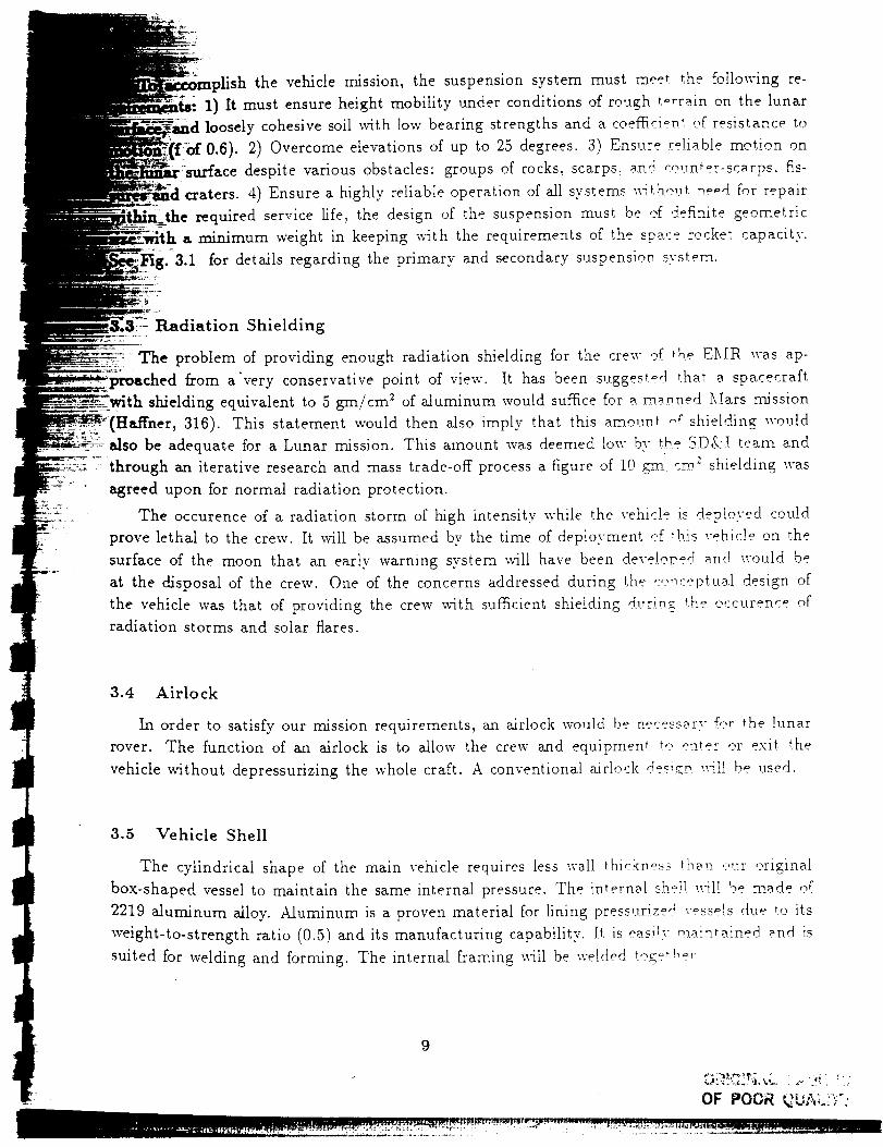
sh the vehicle mission, the suspensionsystem must meet the following re-1) It must ensureheight mobility under conditions of rough terrain on the lunarlooselycohesivesoil with low bearing strengthsand a coefficient ef resistanceto0.6). 2) Overcomeelevationsof up to 25 degrees.3) Ensure reliable motion on
surface despite various obstacles: groups of rocks_scarps, .andceunter-scarps, fis-craters. 4) Ensure a highly reliable operation of all systems\\-itho,.,t needfor repair
required service life, the designof the suspensionmust be ef definite geometrica.minimum weight in keepingwith the requirementsof the sp__.c_rocket capacity.
3.1 for details regarding the primary and secondarysuspensionsystem.
Radiation Shielding
The problem of providing enough radiation shielding for the crew 9f _he E_[R was ap-proached from a'very conservativepoint of view. It has been suggeste4th_at__spacecraft
shieldingequivalent to 5 gm/cm_ of aluminum would sufficefor __,ma.nnedMars mission(FIaffner, 316). This statement would then also imply that this amount ef shielding wouldalso be adequatefor a Lunar mission. This amount wasdeemedlow by _b.eSD&-! team andthrough an iterative researchand masstrade-off processa figure of 10 cm: shielding wasagreedupon for normal radiation protection.
The occurenceof a radiation storm of high intensity while the vehicle is deployed couldprove lethal to the crew. It will be assumedby the time of deployment ef th.is_ehicle on thesurface of the moon that an early warning system will have been develep,e4 and would beat the disposal of the crew. One of the concernsaddressedduring the c,:,r_ceptualdesign ofthe vehicle was that of providing the crew with sufficient shielding durin_gthe occurenceofradiation storms and solar flares.
3.4 Airlock
In order to satisfy our mission requirements,an airlock would be necessaryfor the lunarrover. The function of an airlock is to allow the crew and equipment te enter er exit thevehiclewithout depressurizingthe whole craft. A conventionalairlod< de_i_n_-ill be used.
3.5 Vehicle Shell
The cylindrical shape of the main vehicle requires less wall thickness than e,.tr originalbox-shapedvesselto maintain the sameinternal pressure.The internal sh'_!!xvilI be made of2219aluminum alloy. Aluminum is a proven material for lining pressurizedvesselsdue to itsweight-to-strength ratio (0.5) and its manufacturing capability. It is easily ,--aintained and issuited for welding and forming. The internal framing will be welded teget!,o,.
9

_-t. •
[.
Figure 3.1.
°
I °to
IllIII1111
Z_
FO0 CI_
Z>E3FUZ
3>
-_(
/
g
tP
C-?f-n
V-
IP
21>
zt::JO-UoFU
7< ZC_
-<
b
z
q
Primary and secondary suspension.
10

7
4. AVIONICS
tirimary purpose of the avionics system is to successfully int,,_to,,o_ , a comprehen-
general aviation avionics functions into a more complex ,,_w*_vn_...... architecture t,_
needs by improving the safety and dependability of the vehiclo system operations
g the required a.stronaunts training/experience by over ex_,!oiting advanced
in computers, displays, and overall system design. The overall purpose will be to
_ _stem at an affordable price. The system will be comprised of ._x-ion_ics "vehicle Con-
Arms/Video, Navigation, Communications and Data Transfer/Acquisition to
critical information, improved functional capability, shared electronic displays with-
g important considerations about overall system cost. reliability, producibility, and
maintainability of the entire avionics system. The mass of the te_at avionics system
100 kg -+- 5kg, and the volume of the avionics system is 4.5 m 3 which includes the
a,_onlcs display of 0.5 m a, communication system of 1 m a and workstation, ef 3 m 3. The total
requirement of the avionics system is approximately 600 watts.
Workstation......... The concept for a workstation is envisioned as a modular, reconfigvrable, expandable.
: :_general purpose, human engineered workstation for use by scientists, tech.v.,,-!egists, design and
.system engineers and space and ground operators. The workstation e_.compasses concepts
of machine independence, modularity, standardized interfaces, expert s.vs_e_ technology, and
human machine interaction techniques.
4.2 Input and Output Devices
The primary input device of the workstation is the keyboard which will be attached to
the workstation or will be remote, so astronauts can enter data directly i.- memory without
coming near the workstation. There will be other devices available %r inc'ut such as touch
sensitive screen, optical character reader or light pen. There will be a ctj¢ite[ mouse, or track
ball to enhance the capabilities of the workstation.
4.3 Communication
Regarding communication requirements, the vehicle should bo ab!o ._,, ,:ornmunicate t,:
the base and receive from the base. According to our mission req,.,ire_vo_, tt_o _',_hicle will
have the range of about 1000 km. The vehicle should remain visible to the t:_se. F,:,r .distances
greater than several kilometers, a tower antenna would be needed at tiv" t,,_:_e, tho vehicle. ,:,rboth.
One or more lunar orbiting satellites would also allow communicati,:n between a vehicle
and the base. Use of one low lunar orbit satellite would limit communic.__tie,_ periods to those
11OF PO0_ ;'_' :;" ' _"

the satellite is visible to both the base and the vehicle. Ce.ntinuous communi-
require that several low lunar orbit satellites be spaced appropriately in lunar
4.1 for details.
Performances and Antenna Types
'formance analysis deals with sizing communication system p_ewer and antennas
received signals are strong enough that the data to be se_t can be extra.cted from
are enormous numbers of antenna types corresponding to a ",vide range of gains and
Of all of the antennas available, the dish reflector possesses _ major advantage
it concentrates signal energy on the receiver and thus improves the signaI-to-noise
-Navigation
Navigation for a vehicle on the moon is difficult because the moon does net he_ve a specific
e system as we have on earth with respect to North and South p,,:le. The navigation
! system is divided into the following main displays:
Attitude Indicator - Provides indications of vehicle's pitch and roU. This instrument
indicates PITCH upslope (u) and downslope (d) within a range ,,_" _'_°._ . =_._ The damper
on the side of the indicator can be used to damp out oscillati,:ms.
• Heading Indicator - displays the vehicle heading with respect to I,_,.-ar aorth.
• Bearing Indicator - shows the bearing to the base.
• Distance Indicator - reports distance traveled by the vehicle in i_a_°_,_en_s of I km.
Sun Shadow Device - determines the vehicle's position whith respo,:t _, the sun. This
heading can be compared with the gyro heading at regular mterv_ls as a check against
gyro drift.
• Speed Indicator - shows the vehicle velocity from 0 to 20 l<m t_,.. _nct is ctrive_ by
odometer pulses from the right rear wheels.
• Gyro Torquing Switch - adjusts the navigation gyro to cr, rr'_ct tl,,, HESDING indica-
tion during navigation update.
• Distance Indicator - shows the distance to the base.
12
ORIGINAL P&CaI: ;.__',_ | .OF POOR Q.;i,_..r_

.i
(LW)ORBIT)
_J_!_ _
SA
NEAR SIDEOF UOON
FARSIDE OF MOONVEHICLE ON FARSIDE
SATELITTE (L2)(FAR ORBIT)
VEHICLE LOCATED ON NG B_RD ORBIT)FARSIDE OF MOON
FAR
NEAR BASE ICATION
COMMUNICATION
LOCATED ON NEAR BASE
Communication network.
13 l_ P.2:;_ QUALFF¢

Display
up display will provide the pilot with critical informati,-r_ al,,_,,t human a.sp*_cts.
and the pathfinder. A helmet-mounted x'isuM display avstem pr,__,'ides ar_
th a broad range of ,,-isual information for experiments. Tb _. helmet-mounted
;_ a nearly unlimited field of vision.
*otic Arms
gn of the robotic arm will incorporate key issues of cern_ectness, versatility.
accuracy, and weight. The arm can be used on both the t,.,_r vehicte and lunar
a variety of functions. The lunar vehicle will have two connections for the rebotic
are to be located on the lower center front and rear of vehid,r_
Electronically Scanned Laser Pathfinder
The Electronic Laser Scanner will be a device used on the Lun_.r t_ev=.r to sweep across
_i field of view without any mechanical moving parts by means of laso. r d__ede array(s) and
cameras (CCD), which will measure the distance t,: _.i,,,-_._ between 0...5 and
rs away. The scanner device will guide the Lunar l:t,__ver v@ti,:le _around large to
scale obstacles.
i,
4
.. 4.9 Moving Map Display Processor for finding LC .Path
A VLSI circuit design implements a processor to find the lowest-cest m._p p_tb by associ-
ating a traversal cost at each pixel node and calculating at each nede the tet__l cestef a path
from a unique originator node to that node. This design concept will t?_ very impertant in
the Lunar Rover due to the mission requirement of a distance ef [000 lcrn ,eundtrip
14OF POOR QUALITY

5. THERMAL/FLUID
z i%
• ,onmental Requirements
space environment that will be experienced on the Lunar surface p,?ses many problems
ineer, one of which is the support of life aboard the vehicle. P_,ecause ef the closed
system the ability to revitalize the atmosphere becomes _ m._ior undertaking as
the proper parameters necessary to maintain good_ hea!th for the astronauts.
important conditions are temperature, pressure, humidity. ¢emecsitien. and purity.
gical needs of the astronauts must be quantified and the effecte ,?f cert._in conditions
to ascertain their hazard levels.
Waste Removal and Storage
will consist of a cylindrical tank of thin stainless steel sheet _x-ith an insulation
to reduce heat dissipation. The waste will be treated chemically ,-A_h ._.ctive enzymes
break down the bacteria growth and reduce odors. The ,.trine! sv._tem will be sealed
not in use to reduce accumulation of odors in the latrine. :\ f'__rced _ir system _rill
the toilet to ensure proper direction of waste material. The chemicaI treatment
will be controlled by a flow meter which can sense additions t,, tbo _._nk. The chemical
will consist of sulfuric acid (10(a triple salt monopersulf.ate c__mp,eund) which w'ill
control pH to between 2.0-2.5 and fix free ammonia and atom.emoted compounds.
_ Water upply
_dll be external to allow for modularity and maintenance. A puree wi}! p.,:,:,,-ide ,.,s_abte pres-
__7 _tre for tasks such as showering, waste removal and galley feedwater. T!,e estimated power
--=.::¢xmsumptlon _s 391 W at a flow of 0 456 m hr See Fig o 1 for dotaJ
_:Z.. S.4 Cryogenic Storage
=-_-" . : The atmosphere in the vehicle will be composed of a mixture ,,r _n'- n)tr_.gen __n_d 20%
_= ...... ¢_T. gen, which is very close to the 78.084% nitrogen, 20.9476% ,px.vgen. >!,._.q.traces <,f ,,thor
gases for normal atmospheric breathable Nr. This will be acc,._mp, lisbeA *hr,-,.,gb the s,lpp, ly
of oxygen and nitrogen in two separate cryogenic cylindrical st,,,._,_o _._,!c_ 1,,cared ._utside
the vehicle and mixed accordingly (cryogenic storage tanks are , s,,allv ..t _h-. _pl_'icel. %rm.
but due to space restraints and requirements cylinders a-ill be imp!eme,,_-'A ).
The important concern of safety in the cryogenic fluid storage vo55e _ ;_ e,Jc,'esse, in thre-
separate ways, being;
• 1. The inner-vessel pressure-relief valve
15

RLOCK --__ONTROLLER
__
_/AIRLOCK PUHP
O SENSOR ARRAY
[] CONTROLLER
NOZZLE
DRA[N
WASTE I
[_ HVAC TREATMENT
Figure 5.1. Water supply and waste removal schematic.
16

inner-shell burst-disk assembly
annular-spaceburst-disk assembly
r-
Containment
of leak containment in the vehicle is of high importance. _ecause ef the high
characterizes the lunar environment, maintenance of a suitab_ie atmosphere in
[de is imperative. It was determined that the responses of the crew would be most
the internal pressure of the vehicle would be close to the pressure on earth. The
chosen for the cabin is approximately 12 psi, compared to t4.7 psi at sea level on
_,qth regard to the structure of the vehicle, the inside living quarters cabin shell wiI1
surrounded by- another shell to provide a deterrent to leak propagating.
Airlock Management
The eirlock is the only outlet from the vehicle for the astronauts while on a mission. The
Lirlock has the important function of being the last protection the astro-._,ats have from any
physiological problems which might result from the pressure decrease _-hich occurs during
EVA. For this lunar rover, the plan is to maintain the internal cabin pressure at 12.0 psi.
A compressor will be used to depressurize the airlock. A second cemvresser xrill be carried
in the vehicle as a redundant measure. The compressors will require ae _9re than 15 k'iV of
power during mrlock pumpdown. The first stage of depressurization xx-J!!re.c_iuire 7.2 kW and
the second stage requires I4.9 kW of ,_ower.
5.7 Fire Suppression
The hazard of fire aboard the vehicle is compounded by the clos,_d l,:,ep_ system and the
restrictions it places on the emergency equipment. There are many ways _,_ ,:omb_t a fire. all
use the same basic principle which is removal of oxygen from the fta_v. The tw9 methods
consist of removing the oxygen by removing all air and replacing __1 __v-.,i!__ble oxygen x_ith
inert materials (C02, HMon, dry chemical). These two methods wilt be __,_.p.lement ed through
the use of CO2 in the cabin areas and Halon 1301 in the electrical comevrtments.
17

6. POWER GENERATION
pe Generators
:meet our critical power requirements,a dynamic isotope pewer _vste.mhas been se-isotope usedin the system is Pu2a8- one of a group of re__c_erproduced fuels
Cm242and Cm _44. It should be noted that reactor produced fvels c._,n be _vided
classes: those that absorb one neutron and those that absorb more th_n one neutron.
t_t class, a stable isotope captures one neutron and thus becomes r.a,dioactive. In the
class, a stable isotope (one with a long half-life) absorbs more tb__n one neutron until
up as the desired radioisotope. Pu _as is characteristic of the sece,_d class of fuels.
i_ "ZZ
• Fuel Capsules
Metallic fuel capsules that contain long-lived alpha emitters must ,:,:,-_ain ,a vent for the
helium gas generated by the radioactive decay of the nuclear fuel - ,.,n!e_s ._deq,.tate space is
within the system for such venting to occur. These vents cod be either selective
or nonselective. Selective vents pass helium, but retain any larger gas molecules and solid
_i_::!ii:__ particulates from the fuel. Nonselective vents also retain solid partic,,i_ate_ @ore the fuel. but
,_-.-:_ .......... pass helium and other gaseous effluents, including tmcondensed rue!. imD,,ritv, vapnrs_ and
.... _ possibly other fuel decay products such as radon.
6.3 Overall Design
The overall design of the DIPS power system consists of five ma.i,:,r ,:,:mponents - (1)
a,n isotope heat source, (2) a compressor, (3) a thermal radiator, (4) -_ turbine, and. (5) a
generator. The components have been integrated so that the complete system foIIows a dosed
Brayton cycle configuration. Based on this configuration, heat additie_ _nct rejec_i,_m eccur at
constant pressure, while expansion and compression are assumed _o <,cc,.,,; _t ¢onstant entropy.
To simplify the design of the power system, it was organized so that I),:,et_ the ,-oruprossor and
the turbine make use of the same shaft.
6.3.I Radiator Design
The design of the radiator for the lunar rover will follow a config,,rati,:,,_ involving a series
of tubes through which the coolant will flow. The mass flow rate ,-,f eho ,..... lar_t ebeli,._ml was
found to be 0.0904 kg/s and the specific heat, Cp, was determined _,, t....... _.s_eat value ef
5.193 KJ/Kmol.K.
18

;iderations
.at increasedpower requirements would become n.ec*-ssa,r',. it should bepower conversionunits can be coupled with radiois,:tope he.a.tsources.
the powergenerationrange is extendedbeyond that r.Fact, c__lly obtainable
(such as telluride TE converter systems), and lower ,.,.r_J_costs _,'e obtained
,wet conversion efficiencies. A bar chart of the power ,eq.,.,iremenrs can be
Power
power required for the Lunar Rover while traversi_.g _ 2n ° slope is 43.-_
maximum power requirement for static operation, which inc!,.,cles experimentation.
The maximum power required if dl of the systems are we,.king simultane,>usly
mexirhum operating conditions is ,53.9 kW,.
System
propulsion system for the lunar rover consists of electric rne_,,.,:_ d..esigned to meet
mg requirements: variable torque, variable speed, light wei._bt, t__igh etq:ic{encv.
torque for obstacle clearance combined with optimum speed to m._:.:.J..rrtize tlae vehicle's
loration range.
. .._-_-_ .1 Motor
___ sensing system, (3)electronic commutator and control. The brus.h.!esz m,._,,:,, c,msis_s of __
___::i.:i _ rotor on which permanent magnets are mounted. These magnets .are alw._v_ _rr__nged. in pole
_'_-.:.: pairs. The winding is placed in an external, slotted stator.
6.6.2 Power Control Methods
The method of power control to be used in this system will in_i,,_ a '.arving supply
voltage to the commutation svstem. The six switching transist,:,rs will ,:,,,71v,.,I ,:c,mmutation
at the proper angular intervals and the series connected power transist,:,,.=- will haz_dle velocit3
and current control of the brushless motor. This can be accomplished t,,.- r,,,ls,,-,vidth ,:,_'pulse-
frequency modulation.
6.6.3 Tachometers
Tachometers are often necessary in lligh-performance serv,_ app]i,:._ti,,,_. ,,'-t_0,.'e _}_ev pr,,-
vide velocity feedback for speed control purposes or servo system st_aL_i!;_',. g,:,r tl_i._ system.
19
• - i-

ZZ_X
ZCZ_
-Dr-]
(Fq7D
7DU]_Z)
t-----4
7_3r_-(r_z-4(.4
6o--4o,o zI>-4r-r_r--z6,o
--[379r-]tzJc(-)r-q
r-r](/,)r_7D
<r_
CZtzJ
73
(Z>
CDPOCZ)
w
A
(
CZ)
(
CZD
cnCZ)
64---jE>-4
t-B
Figure 6.1. Power requirements for lunar rover.
2O
0%CD
X--
(
ORIGINAL P._GE ISOF POOR QUALITY

brushless DC tachometer will be used. This tachometer is ba.sed on a per-
motor and a multi-coil stator structure, which is c,>m.m,.,t__.ted by _an _.[SI
21
OF POOF_, QU_;..!P(

college, so the benefits of participation in the Advanced Design' both universities. The faculty of the college expect that the general
ties and Collegewill continue to comefrom involvement in real-world;_m._pportof new initiatives in engineeringdesigneduc.atien, recruitment of
students,and participation with students from ether universities in the'.conferences.
by our faculty in the AdvancedDesignProgram will come,as it has in theg designcoursesand supervising designprojects that are established as a
from the AdvancedDesignProgram. Specificbenefitsinclude involvement ofin currentNASA projects, personalinteractions with NASA Center contacts,
for interdisciplinary teachingand research.
major benefit to our students will Comefrom working as project team memberson, system-level,open-ended,interdisciplinary designproblems. Theseare the kinds
they will work on after graduation. Our claim for this benefit is supported by_erienceof our graduates.
Looking to the future, this year's class, which has begun iziterviewing for jobs, reports
Jtantial interest among employers in the student's experience in cut Advanced Design
gram supported system design project. We think this approach te teaching engineering:ide_gn works, and we will continue it.
22ORIG!NAL P,_2EZ IS
OF POOR QUALITY