Embed Size (px)
Citation preview

P-04-128
Svensk Kärnbränslehantering ABSwedish Nuclear Fueland Waste Management CoBox 5864SE-102 40 Stockholm Sweden Tel 08-459 84 00 +46 8 459 84 00Fax 08-661 57 19 +46 8 661 57 19
Oskarshamn site investigation
Gravity measurements in the Laxemar model area with surroundings
Carl-Axel Triumf, GeoVista AB
June 2004

ISSN 1651-4416
SKB P-04-128
Oskarshamn site investigation
Gravity measurements inthe Laxemar model areawith surroundings
Carl-Axel Triumf, GeoVista AB
June 2004
Keywords: Gravity, Magnetic total field, GPS, Granitoids, Quartz-monzodiorite,Laxemar, Götemar, Geometry, Modelling.
This report concerns a study which was conducted for SKB. The conclusionsand viewpoints presented in the report are those of the author(s) and do notnecessarily coincide with those of the client.
A pdf version of this document can be downloaded from www.skb.se

Abstract
GeoVista AB has carried out measurements, processing, interpretation and analysis of gravity and magnetic total fields during March to June 2004. The activity focused on the Laxemar area and its nearest surroundings with the aim to reveal the possible general dip of the quartz-monzodiorite, gabbroic and dioritic rocks found in the southern part of the area. If these rocks dip towards north they could occur at depth in the Laxemar area.
The results of this activity indicate that the quartz-monzodiorite and the gabbroic and dioritic rocks found at the contact to Ävrö granitoids are dipping towards north. The rocks observed in the deep borehole KLX02 support this conclusion. The prognosis is however uncertain, partly because of the inherent ”principle of ambiguity” prevalent in all potential field modelling.
Modelling of the Götemar granitoid supports the results earlier obtained by /Nisca,1987/, i.e. the southern contact of the Götemar granitoid is estimated to dip towards south below the Laxemar model area at a depth which is beyond the direct interest of the site investigation. It can however not be excluded that minor sub-units of the Götemar granitoid could appear at less depth in the Laxemar model area.

Sammanfattning
Mätningar samt tolkning och analys av tyngdkraftsfältet och det magnetiska totalfältet har genomförts av GeoVista AB i Laxemarområdet med omgivning under mars till juni 2004. Det primära syftet var att undersöka stupningen hos de bergarter som återfinns i den södra delen av Laxemarområdet. Dessa bergarter utgörs av kvartsmonzodiorit och gabbroider och dioritoider som i norr gränsar mot Ävrögranitoider. Om dessa bergarter stupar mot norr in under Ävrögraniterna kan de komma att uppträda i den del av berggrunden under Laxemarområdet som är föremål för de pågående platsundersökningarna.
Resultaten av mätningarna och den efterföljande tolkningen och analysen visar att kvartsmonzodiorit, gabbroider och dioritoider torde stupa mot norr. Utsagan som dock är behäftad med viss osäkerhet, bl.a. för att all potentialfältsmodellering lyder under den s.k. mångtydighetspricipen, stöds av den geologi som påträffas i de djupare partierna av KLX02.
Vid modelleringarna har också geometrin hos Götemargraniten studerats. Resultaten av modelleringarna inom den föreliggande aktiviteten stöder tidigare resultat av /Nisca, 1987/, d.v.s. Götemargranitens södra kontakt torde stupa mot söder under modellområdet för Laxemar. Det kan således inte uteslutas att delar av Götemargraniten kan förekomma inom modelldjup.

5
Contents
1 Introduction 7
2 Objective and scope 9
3 Equipment 113.1 Description of equipment 113.2 Description of software and programme modules 11
4 Execution 134.1 Measurements of gravity 134.2 Measurements of the magnetic total field 134.3 Processing of gravity survey data 134.4 Processing of magnetic survey data 154.5 Interpretation 164.6 Nonconformities 16
5 Results 175.1 Gravity and magnetic data 175.2 Modelling 21
6 Discussions 27
References 29
Appendix 1 List of gravity data 31Appendix 2 Lists of model parameters in GMM format for profiles P1 and P2 35

7
1 Introduction
This document reports the results of the measurements and interpretation of gravity and magnetic total field carried out by GeoVista AB in March to June 2004 in the Laxemar model area with its surroundings. It is one of the activities performed within the site investigation at Oskarshamn. The work was carried out in accordance with activity plan AP PS 400-04-002. In Table 1-1 controlling documents for performing this activity are listed. Both activity plan and method descriptions are SKB’s internal controlling documents.
Table 1-1. Controlling documents for the performance of the activity.
Activity plan Number Version
Geofysiska undersökningar med tyngdkraftsmätning, magnetometri och petrofysik främst inom det lokala modellområdet AP PS 400-04-02 1.0
Method descriptions Number Version
Metodbeskrivning för gravimetri SKB MD 212.003 1.0
Metodbeskrivning för markbaserad magnetometri SKB MD 212.004 1.0
The gravity was measured at 74 stations, where 28 stations are located along an approximately 5 km long profile crossing the Laxemar area. The rest of the stations are distributed in the surroundings filling larger gaps between the gravity stations measured by Swedish Geological Co (SGAB) in 1987 /Nylund, 1987/. Furthermore, one gravity station was measured in Oskarshamn at a fundament of a balance. Measurements of the magnetic total field were carried out only along the profile crossing the Laxemar area (Figure 1-1).
The measurements and part of the processing was done by Timo Pitkänen and Malte Wallgren, GeoVista AB. Part of the processing and the entire interpretation was carried out by Carl-Axel Triumf, GeoVista AB.

8
Figure 1-1. Distribution of gravity stations measured 2004 and 1987, and the profile measured with magnetometry 2004 (M=Mederhult, LF=Lilla Fjälltorpet, SPP=Simpevarp Power Plant).

9
2 Objective and scope
The purpose of the measurements of gravity and magnetic total field was to gain more information about the geometrical distribution at depth of major rock units in the Laxemar area. Among the rocks of major concern are the mafic rock bodies (eg. gabbro and diorite) and quartz monzodiorite that are frequently occurring in outcrops at the southern part of the Laxemar area. Furthermore the Götemar granitoid situated north of the Laxemar area, which earlier has been modelled by /Nisca, 1987/, is of interest as the result of Niscas modelling indicates a southern dip of the southern contact of the Götemar granitoid.
The outcome of the present study will primarily be used as supportive information to guide other investigation activities, such as drilling. The results may however also be used in modelling of the lithological part of the site descriptive model.
11
3 Equipment
3.1 Description of equipmentThe measurements of gravity and the magnetic total field were carried out using the following equipment:
• Gravity meter LaCoste Romberg GT624 upgraded with module ALIOD 100.
• Magnetometer, base station, GEM Systems GSM-19, Overhauser total field.
• Magnetometer, roving, GEM Systems GSM-19, Overhauser total field, with GPS-module (Marconi Super Star II), used in “walking-mag mode”.
• GPS Trimble 4700 RTK GPS System with radio Trimtalk 450S.
• Handheld GPS, type Garmin XL12.
3.2 Description of software and programme modulesDuring processing and interpretation the following software was used:
• Geosoft Oasis Montaj (Geosoft Inc.) for gridding, analysis and map production.
• MapInfo Professional (MapInfo Corporation), for analysis, presentation and map production.
• ArcView (Environmental Systems Research Institute Inc.) for presentation and map production.
• Microsoft Excel (Microsoft Corp.) for general calculations.
• Microsoft Word (Microsoft Corp.) for reporting.
• An Excel-module, International Gravity Formula Calculator, for the calculation of the normal gravity at a certain location on the geoid.
• GTRANS 3.51 (Lantmäteriet) for co-ordinate transforms at office and, interactively on the home page of Lantmäteriet with GTRANS 3.4.
• ASC2GVG and GRD2GVG (GeoVista AB) for the preparation of input files for the terrain correction.
• TCTEM5 (GeoVista AB) for the terrain correction.
• GMM (GeoVista AB) for modelling of gravity and magnetic fields.
• Adobe Acrobat and Adobe Distiller (Adobe Systems Inc.) for preparation of illustrations in the report.

13
4 Execution
4.1 Measurements of gravityMeasurements of gravity were carried out using a gravity meter and RTK (real-time kinematic) GPS for the determination of gravity and X-, Y-, Z- coordinates of the gravity stations.
In the gravity survey two base stations were used, one named “3906” and the other “Äspöbas”. All measurements were adjusted to the station “3906” where the absolute gravity value expressed in the system ECS62 should be 981697.661 mGal /Aaro, 2004/. The base station was visited around four times a day in order to control the drift of the gravity meter.
The GPS survey utilised measurements in the real-time kinematic mode with two receivers. One was located at the reference station (fix point) and the other functioned as a roving receiver. The correction of the values according to the model of the geoid (SWEN 01L) was not carried out simultaneously during the measurements. Instead the correction was done afterwards and resulted in altitudes expressed in RH70 and co-ordinates in the X-Y-plane expressed in RT90 2,5 gon V. The accuracy in altitude is estimated at better than ± 10 cm.
Each gravity station received an ID- code. Along the profile across Laxemar a line ID- code was used: LSM001105-01 to LSM001105-28. Gravity stations outside the profile were given a point ID- code: PSM003665 to PSM003710. All gravity stations along the profile and elsewhere has however been joined into a grid file by SKB with the grid ID- code GSM000011. The gravity station in Oskarshamn received the code “Instrument workshop”.
4.2 Measurements of the magnetic total fieldMeasurements of the magnetic total field were done by the use of one roving magnetometer with a built-in GPS receiver. The roving magnetometer was used in “walking-mag” mode with a typical point distance of less than 2 m. Natural fluctuations in the earth’s magnetic field were at the same time recorded at a base station.
The data from the measurements of the magnetic total field have been stored under the line ID- code LSM001105.
4.3 Processing of gravity survey dataThe gravity survey has used the point 3906 as reference point, the point is also called SKB.3929 /Aaro, 2004/. The absolute gravity at the point is 981697.661 mGal expressed in the system ECS62. The terrain corrected Bouguer anomaly is -183,82 gravity units (gu) according to the data received from SKB. The processing of the gravity survey of GeoVista AB has used the ECS62 system in order to achieve a conformity with the former survey carried out by SGAB in 1987 /Nylund, 1987/.

14
In the processing the formula for the normal gravity according to Potsdam 1930 has been used. The terrain correction applied is based on the use of the triangular-element method as presented by /Zhou et al, 1990/. The method has been implemented in an algorithm called TCTEM5. For the terrain correction a grid of the altitude with a cell size of 50 m was used together with a search radius much larger than the dimensions of the grid. The altitude grid used has an extent according to Figure 4-1. This means that contributions to the gravity in every measured point from all undulations occurring in the used 50 m grid are considered. The morphology in the area is gently undulating with a minimum altitude of 0 m at the sea and approximately 55 m in the western part of the altitude model area. The terrain correction method used is considered sufficiently accurate in the perspective of the morphology of the area and the problem to be solved.
Figure 4-1. Distribution of gravity stations measured 2004 and the extent of the altitude grid used for the terrain correction (M=Mederhult, LF=Lilla Fjälltorpet, SPP=Simpevarp Power Plant).

15
It is not entirely clear from the report by /Nylund, 1987/ how far from the gravity stations that the contributions to gravity from the terrain were considered, in the gravity survey done by SGAB. Before invoking into the national database of gravity, these new gravity data gathered in the present activity, it is important to take measures to preserve conformity in the use of variables in the terrain correction. It has thus been suggested that the Geological Survey of Sweden (SGU) should do a postponed terrain correction according to the national standards. This could however be done independently of this activity.
The parameters used in the first part of the processing of gravity data are presented in Table 4-1.
Table 4-1. Parameters used in the first part of the processing of gravity data from the measurements made by GeoVista AB in March 2004.
Gravity system ECS62 with 1930 gravity formula (Potsdam)
Absolute value at 3906 981697.661 mGal (SKB.3929)
Calculation of normal gravity Calculation of normal gravity according to formula according to formula
Calculation of latitude X and Y in RT90 2,5 gon V converted with program Gtrans 3.51 (at GeoVista AB) and interactively on the Internet (Gtrans server 3.4) to RT90 Latlong
Free air correction 0.3086 x altitude
Bouguer correction 0.4191 x density x altitude (density 2670 kg/m3)
Terrain correction TCTEM5 /Zhou et al,1990/, search radius 1000000 m
The second part of the processing included the joining of data from the survey of SGAB /Nylund, 1987/ and the data from the GeoVista AB survey of 2004 followed by the gridding of gravity data. The gridding was done with the routine for “Minimum curvature gridding” in Geosoft’s Oasis Montaj. The resulting grid had a cell size of 50 by 50 m.
4.4 Processing of magnetic survey dataThe processing of magnetic data included correction for fluctuations in the magnetic total field at the base station and de-spiking of data. Furthermore measuring points with obviously erroneous positions as determined by the in-built GPS were removed.
As the modelling also addressed the dip of the Götemar granitoid data from the airborne survey of the magnetic total field made by Geological Survey of Sweden (SGU) in 1986 was also prepared for interpretation. The reason for not using the data from the helicopter survey made 2002 /Rønning et al, 2003/ was lack of coverage in the northern part of the area of interest, i.e. over the Götemar granitoid.

16
4.5 InterpretationThe preparatory work carried out before the interpretation included an inventory of petrophysical data available from the bedrock surface within the Laxemar and Götemar area. Preliminary petrophysical data from fieldwork done by Geological Survey of Sweden (SGU) within the bedrock mapping programme of SGU were made available /Hult, 2004/. Petrophysical studies /Mattsson and Thunehed, 2003; Mattsson et al, 2003/ made within the site investigation together with the data from SGU were implemented into a GIS to assist in the setting of parameters in the forthcoming modelling. /Nisca, 1988/ presents petrophysical data from boreholes KLX01 and from the surface, however without co-ordinates connected to specific specimens in /Nisca, 1987/. Geological data from the boreholes KLX01, KLX02 and KLX04 were also examined /Hultgren, 2004/.
The interpretation of the geophysical data collected in this activity was dominated by joint modelling of data of the gravity field and the magnetic total field. The modelling was done in a pragmatic manner where only the main tasks were addressed, i.e. to find out the probable main dip of the rock units in the Laxemar area and it’s surroundings. This means that only a sufficiently god fit - not meaning perfect - between measured/gridded data and modelled data was aimed at.
4.6 NonconformitiesThere are no major non-conformities as compared to the activity plan.

17
5 Results
The results of this activity are stored in the primary data bases (SICADA and GIS) with the Field Note no. 298.
5.1 Gravity and magnetic dataThe result of the gravity survey carried out 2004 is presented in Appendix 1. The data from the present activity and the data from the SGAB survey of 1987 /Nylund, 1987/ are presented together in Figure 5-1.
Figure 5-1. The terrain corrected Bouguer anomaly and the distribution of gravity stations from gravity surveys of 1987 and 2004. Bluish colour marks low gravity field and greenish-yellowish-reddish high gravity field (M=Mederhult, LF=Lilla Fjälltorpet, SPP=Simpevarp Power Plant).

18
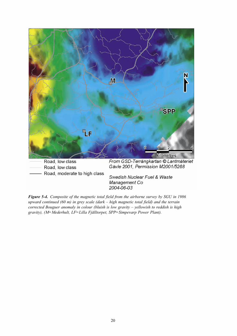
From the Simpevarp power plant towards west, a gravity maximum is found. It passes in-between Lilla Fjälltorpet and Mederhult where the strike bends slightly towards northwest. The cause of the maximum is partly due to the two nearby minima caused by the Götemar granitoid in the north and the Uthammar granitoid in the south. Both are clearly visible in Figure 5-1. The peak of the maximum however occurs where the quartz-monzodiorite and the dioritoids and gabbros are found. The dioritoids and gabbros occur as bodies of varying sizes near the northern contact between the quartz-monzodiorite and the Ävrö granitoids. The density of all these rocks is generally higher as compared to the surrounding Ävrö granitoids.
The magnetic total field from the airborne survey of SGU in 1986 is shown in Figure 5-2 together with the points where the magnetic total field was measured on ground 2004. A pronounced magnetic maximum is associated with the dioritoids and the gabbros located near the northern contact of the quartz- monzodiorite as explained above. Magnetic
Figure 5-2. The magnetic total field from the airborne survey by SGU in 1986 upward continued (60 m). The distribution of points where the magnetic total field was measured on ground 2004 in blue. Bluish colour marks low magnetic total field and yellowish- reddish - pinkish high field (M=Mederhult, LF=Lilla Fjälltorpet, SPP=Simpevarp Power Plant).

19
susceptibilities as measured on outcrops often take very high values in this area. The profile partly passes in a semi-parallel direction with the main strike of these magnetised units, causing an apparent false “thickness” of the source body when studying a profile plot only (Figur 5-3).
A graph of the magnetic total field along the profile is shown in Figure 5-3.
A composite image of both the gravity and the magnetic total field is shown in Figure 5-4. It is obvious from the image that the magnetic maximum described above is connected to the gravity maximum. It is also quite clear that there is quite a substantial portion of the gravity high located south of the magnetic maximum. This gravity high is associated with the quartz-monzodiorite that, in this area, appears to have a low relative magnetic susceptibility as compared to the surrounding Ävrö granitoids.
Figure 5-3. The magnetic total field from the ground survey 2004 along the profile crossing the Laxemar area. Missing data marks areas with noise. The southern-most part of the profile is to the left in the figure.
Profile across Laxemar0=1549668/6364017
4550=1547573/6368056
50000
50500
51000
51500
52000
52500
0 1000 2000 3000 4000 5000distance [m]
mag
netic
tota
l fie
ld [n
T]
20
Figure 5-4. Composite of the magnetic total field from the airborne survey by SGU in 1986 upward continued (60 m) in grey scale (dark – high magnetic total field) and the terrain corrected Bouguer anomaly in colour (bluish is low gravity – yellowish to reddish is high gravity), (M=Mederhult, LF=Lilla Fjälltorpet, SPP=Simpevarp Power Plant).

21
5.2 ModellingThe modelling was carried out using a 2,5-D model. The basic parameters for the modelling presented in Table 5-1 is in accordance with the properties of the more silicic portions of the Ävrö granitoids found in the area.
Table 5-1. Basic parameters used in the modelling of the response in gravity and magnetics.
Magnetic field intensity [nT] 50440
Inclination of magnetic field [degrees] 71
Background density [kg/m3] 2680
Background magnetic susceptibility [SI] 0.022
The location of the modelled profiles is shown in Figure 5-5. The profiles P1, P2, P3 and P8 are passing over the gravity maximum. The intention with these four profiles is to model the dip of the rock units in the Laxemar area including the Götemar granitoid. Profile P6 is traversing the Götemar granitoid in a roughly west-easterly direction with the main focus to enlighten the possible dip of the contacts of the Götemar granitoid.
Figure 5-5. Location of modelled profiles displayed on the terrain corrected Bouguer anomaly in colour (bluish is low gravity – yellowish to reddish is high gravity), (M=Mederhult, LF=Lilla Fjälltorpet, SPP=Simpevarp Power Plant).

22
The distribution of petrophysical samples with known co-ordinates is visible in Figure 5-6. The spatial distribution of samples is somewhat concentrated to the ridge in gravity while the area south of it is only sparsely covered. The coverage of petrophysical data may be sufficient to solve the major task of this activity, i.e. to indicate a possible geometrical distribution of rocks in the Laxemar area. The comparatively sparse coverage is one of the reasons behind leaving the short wavelength anomalies without a good fit between the measured and modelled data. It is however believed that such an achievement, of a very good fit between measured and modelled data, would not substantially alter the general conclusions of this work.
Figure 5-6. Location of modelled profiles and location of petrophysical sampling is displayed on the terrain corrected Bouguer anomaly (bluish is low gravity – yellowish to reddish is high gravity), (M=Mederhult, LF=Lilla Fjälltorpet, SPP=Simpevarp Power Plant).

23
The general results from the entire modelling of the rock units in the Laxemar area are well represented by the modelling results from profiles P1 and P2 that are shown in Figures 5-7 and 5-8 together with approximate projections of nearby core bore holes. All the modelling results suggest a main dip towards north of the rock units within the Laxemar area. The rocks found in the core borehole KLX02 and the physical properties recorded in the borehole support this result. According to the modelling of gravity and magnetics the geometrical unit containing gabbroic and dioritic rocks is supposed to be found at a depth of around 1500 m adjacent to the core borehole KLX02. As these rocks have extremely high magnetic susceptibilies in comparison to most other rocks in the region, it should be rather easy to identify the units if cut by a borehole. In /Ekman, 2001/ the composite log of geological and geophysical data from borehole KLX02 is presented. In the section 1379-1405 m a “greenstone” is reported. It coincides with a section where the magnetic susceptibility is the highest measured in the entire borehole. According to the modelling results, and also to field data, the quartz-monzodiorite is expected to be found below the gabbroic-dioritic section provided the dip is towards north. In the revised mapping of the borehole /Hultgren, 2004/ a quartz-monzodiorite is also found below this highly magnetised unit. These observations thus give strong support to the modelling result.
The models in Figures 5-7 and 5-8 are presented explicitly in Appendix 2, in a format fitting the GMM modelling software used. In the appendix the physical properties and geometries for the individual source bodies can be found.
From Figures 5-7 and 5-8 it is also possible to observe the modelled dip of the Götemar granitoid located north of the Laxemar area. The results are in general accordance with the results presented by /Nisca, 1987/, where the southern contact of the Götemar granitoid appears to dip towards south. The profile P6 (not explicitly presented here) crosses the Götemar granitoid in a west-easterly direction. Along P6 the result indicates a fairly steep dip at the western contact and an eastward dip at the eastern contact.
Figure 5-7. Result of the modelling of gravity (blue dots are sampled data from grid and blue line is the response from the model) and magnetic total field data and response (in brown) along profile P1. The Götemar granitoid and the Uthammar granitoid are red, the quartz-monzodiorite is pink, the gabbroids/dioritoids are green, the Ävrö granites are reddish-pinkish with or without black pattern, where a pattern indicates higher magnetic susceptibility. The background properties in the model (yellow) are typical for the portion of Ävrö granitoids that have densities around 2680 kg/m3. Approximate projections of the core boreholes KLX01 and KLX02 is shown.
2 km
0 kmKLX02 KLX01
S N
24
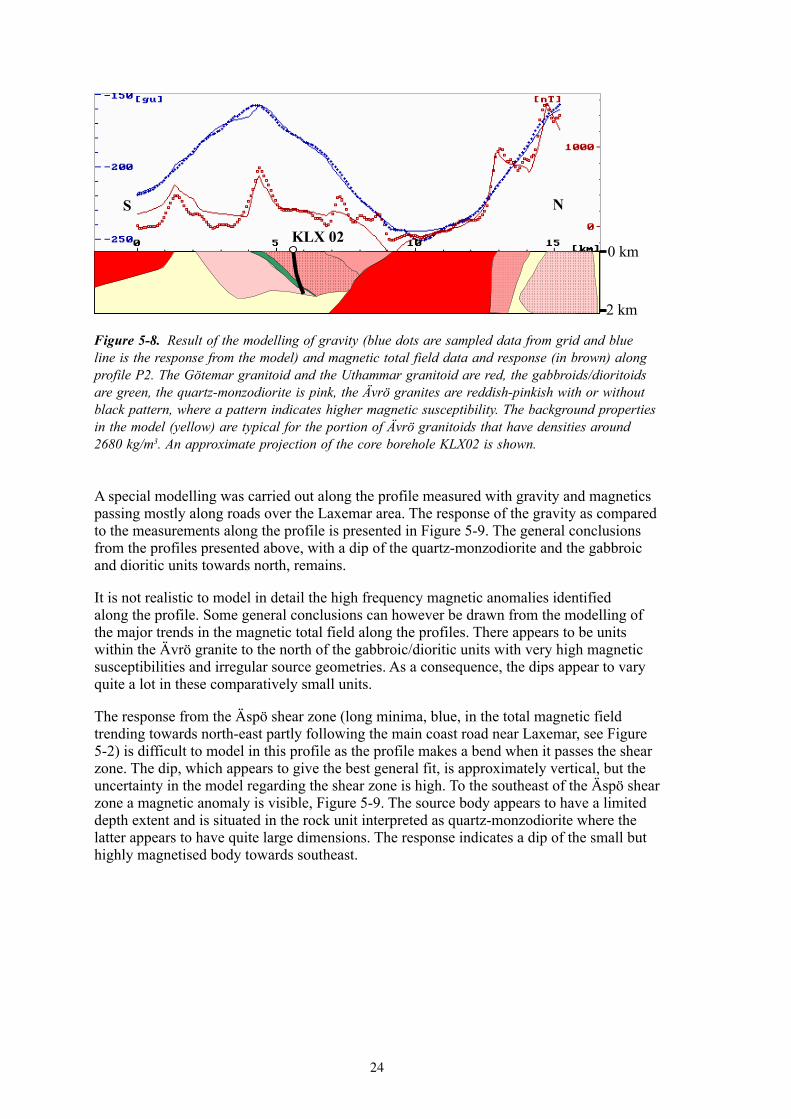
A special modelling was carried out along the profile measured with gravity and magnetics passing mostly along roads over the Laxemar area. The response of the gravity as compared to the measurements along the profile is presented in Figure 5-9. The general conclusions from the profiles presented above, with a dip of the quartz-monzodiorite and the gabbroic and dioritic units towards north, remains.
It is not realistic to model in detail the high frequency magnetic anomalies identified along the profile. Some general conclusions can however be drawn from the modelling of the major trends in the magnetic total field along the profiles. There appears to be units within the Ävrö granite to the north of the gabbroic/dioritic units with very high magnetic susceptibilities and irregular source geometries. As a consequence, the dips appear to vary quite a lot in these comparatively small units.
The response from the Äspö shear zone (long minima, blue, in the total magnetic field trending towards north-east partly following the main coast road near Laxemar, see Figure 5-2) is difficult to model in this profile as the profile makes a bend when it passes the shear zone. The dip, which appears to give the best general fit, is approximately vertical, but the uncertainty in the model regarding the shear zone is high. To the southeast of the Äspö shear zone a magnetic anomaly is visible, Figure 5-9. The source body appears to have a limited depth extent and is situated in the rock unit interpreted as quartz-monzodiorite where the latter appears to have quite large dimensions. The response indicates a dip of the small but highly magnetised body towards southeast.
Figure 5-8. Result of the modelling of gravity (blue dots are sampled data from grid and blue line is the response from the model) and magnetic total field data and response (in brown) along profile P2. The Götemar granitoid and the Uthammar granitoid are red, the gabbroids/dioritoids are green, the quartz-monzodiorite is pink, the Ävrö granites are reddish-pinkish with or without black pattern, where a pattern indicates higher magnetic susceptibility. The background properties in the model (yellow) are typical for the portion of Ävrö granitoids that have densities around 2680 kg/m3. An approximate projection of the core borehole KLX02 is shown.
2 km
0 kmKLX 02
S N

25
Figure 5-9. Result of the modelling of gravity (dots are measured data and line is the response from the model) along the profile traversing the Laxemar area.The quartz-monzodiorite is pink, the Ävrö granites are reddish-pinkish with or without black pattern. A pattern indicates higher magnetic susceptibility. The modelled Äspö shear zone is marked in blue. The background properties in the model (yellow) are typical for the portion of the Ävrö granitoids that have densities around 2680 kg/m3.
0 m
1000 m
SE NW

27
6 Discussions
Modelling of the gravity and the magnetic total fields has been carried out in order to indicate possible general source geometries to anomalies in the Laxemar model area with surroundings.
The modelling has been performed in a pragmatic manner i.e. without striving towards a perfect fit between measured and modelled data. Instead, the modelling has stopped at a fit that has been judged as sufficient for the task to solve. Though a better fit between measured and modelled data could be achieved, primarily by introducing source bodies of smaller dimensions, such an action has not been considered justifiable.
The measurements of the magnetic field along the profile traversing the Laxemar area have at sections suffered from high noise level, especially near the power lines. The point density in the sampling of the magnetic field has been very high and as a result numerous short wavelength anomalies have been identified. It has not been realistic, neither advisable from a problem oriented view, to model these scattered and rather small anomaly sources. Instead, only the general trends in the magnetic field along this profile have been modelled together with the gravity.
Though the fit between measured and modelled data could be improved it is believed that the general character of the models used will remain. The models indicate that the quartz- monzodiorite, and the gabbroic and dioritic bodies apparently associated with its northern contact towards the Ävrö granitoids, are occupying at least some part of the volume under the Laxemar area. The results from the deep core borehole KLX02 also support this conclusion.
Regarding the geometry of the Götemar granitoid limited effort only has been put to model the dip of its contact. The results achieved however support the conclusions by /Nisca, 1987/ where the southern contact appears to dip towards south. According to the modelling the main body of the Götemar granitoid probably intrudes the Laxemar model area at a depth which is beyond the direct interest of the site investigation. It can however not be excluded that minor sub-units of the Götemar granitoid could appear at less depth in the Laxemar model area.
The modelling of potential field is governed by the problems introduced by the “principle-of-ambiguity”. This principle states that an infinite number of solutions are available to explain a potential field distribution. One way of bringing down the number of possible solutions is to introduce “a-priori” information about the objects to model. Such information could be knowledge of the surface geology and the physical properties available from sampling activities. These constraints have been used to a sufficient extent in this work, but still the uncertainties in the model regarding both geometry and physical properties are judged to be moderate to high.

29
References
Aaro S, 2004. Personal communication. Geological Survey of Sweden, Uppsala.
Ekman L (editor), 2001. Project Deep Drilling KLX02 – Phase 2. Methods, scope of activities and results. Summary report. SKB TR-01-11, Svensk Kärnbränslehantering AB.
Hult K, 2004. Personal communication. Geological Survey of Sweden, Uppsala.
Hultgren P, 2004. Personal communication. Swedish Nuclear Fuel and Waste Management Co.
Mattsson H, Thunehed H, 2003. Simpevarp site investigation. Measurements of petrophysical parameters on rock samples during autumn 2002. SKB P-03-19, Svensk Kärnbränslehantering AB.
Mattsson H, Thunehed H, Triumf C A, 2003. Oskarshamn site investigation. Compilation of petrophysical data from rock samples and in situ gamma-ray spectrometry measurements. SKB P-03-97, Svensk Kärnbränslehantering AB.
Nisca D, 1987. Aerogeophysical interpretation bedrock and tectonic analysis. SKB HRL Progress Report 25-87-04, Svensk Kärnbränslehantering AB.
Nisca D, 1988. Geophysical laboratory measurements on core samples from KLX01, Laxemar and KAS02, Äspö. SKB HRL Progress Report 25-88-06, Svensk Kärnbränslehantering AB.
Nylund B, 1987. Regional gravity survey of the Simpevarp area. SKB HRL Progress Report PR 25-87-20, Svensk Kärnbränslehantering AB.
Rønning J H S, Kihle O, Mogaard J O, Walker P, 2003. Simpevarp site investigation. Helicopter borne geophysics at Simpevarp, Oskarshamn, Sweden. SKB P-03-25, Svensk Kärnbränslehantering AB.
Zhou X, Zhong B, Li X, 1990. Gravimetric terrain corrections by triangular-element method. Geophysics, Vol. 55, Issue 2. (February) p. 232 – 238.

31
Appendix 1
List of gravity data
1
Appendix 1
List of gravity data Station Northing
[RT90 2,5gonV]
Easting [RT90 2,5gonV]
Eleva-tion[m]
Normal gravity value for latitude in RT90 according to International Gravity Formula Calculator, 1930Potsdam [mgal]
Bouguer anomaly [mgal]
Bouguer anomaly [g.u.]
Terrain corrected Bouguer anomaly [g.u.]
Absolute gravity value at "Instru-mentworkshop" excluding terrain correction [mGal]
Instrument workshop 6348505 1539941 4,20 981703,74 -15,21 -152,1
noterrain correc-tion 981700,77
LSM001105-01 6368049 1547545 13,29 981718,10 -18,25 -182,5 -182,07
LSM001105-02 6367889 1547552 18,07 981717,98 -18,15 -181,5 -180,45
LSM001105-03 6367695 1547471 19,92 981717,84 -18,20 -182,0 -181,76
LSM001105-04 6367562 1547571 17,52 981717,74 -18,10 -181,0 -180,40
LSM001105-05 6367435 1547637 26,90 981717,65 -18,00 -180,0 -178,78
LSM001105-06 6367184 1547616 23,43 981717,46 -17,91 -179,1 -178,68
LSM001105-07 6366951 1547672 20,90 981717,29 -17,51 -175,1 -174,08
LSM001105-08 6366785 1547770 19,88 981717,17 -17,32 -173,2 -172,80
LSM001105-09 6366687 1547841 18,63 981717,10 -17,16 -171,6 -171,39
LSM001105-10 6366440 1547946 18,83 981716,91 -17,03 -170,3 -170,05
LSM001105-11 6366373 1547987 21,75 981716,86 -16,95 -169,5 -168,99
LSM001105-12 6366254 1548100 19,82 981716,77 -16,81 -168,1 -167,79
LSM001105-13 6366116 1548202 17,20 981716,67 -16,63 -166,3 -166,00
LSM001105-14 6365948 1548244 13,26 981716,55 -16,33 -163,3 -163,13
LSM001105-15 6365821 1548286 14,05 981716,45 -15,99 -159,9 -159,73
LSM001105-16 6365712 1548439 15,40 981716,37 -15,85 -158,5 -158,18
LSM001105-17 6365598 1548540 10,42 981716,29 -15,70 -157,0 -156,67
LSM001105-18 6365478 1548625 14,40 981716,20 -15,75 -157,5 -156,78

322
Station Northing [RT90 2,5gonV]
Easting [RT90 2,5gonV]
Eleva-tion[m]
Normal gravity value for latitude in RT90 according to International Gravity Formula Calculator, 1930Potsdam [mgal]
Bouguer anomaly [mgal]
Bouguer anomaly [g.u.]
Terrain corrected Bouguer anomaly [g.u.]
Absolute gravity value at "Instru-mentworkshop" excluding terrain correction [mGal]
LSM001105-19 6365413 1548720 11,33 981716,15 -15,69 -156,9 -156,68
LSM001105-20 6365303 1548908 6,72 981716,07 -15,36 -153,6 -152,55
LSM001105-21 6365205 1549098 9,81 981715,99 -15,71 -157,1 -156,77
LSM001105-22 6364864 1549448 4,92 981715,74 -16,42 -164,2 -163,93
LSM001105-23 6364936 1549371 9,20 981715,79 -15,87 -158,7 -158,58
LSM001105-24 6364689 1549613 7,25 981715,61 -16,35 -163,5 -163,34
LSM001105-25 6364548 1549593 8,23 981715,50 -16,80 -168,0 -166,91
LSM001105-26 6364367 1549606 3,78 981715,37 -17,21 -172,1 -171,91
LSM001105-27 6364170 1549575 3,36 981715,22 -17,44 -174,4 -174,22
LSM001105-28 6363988 1549684 4,82 981715,09 -17,55 -175,5 -175,27
PSM003665 6366143 1546593 16,99 981716,71 -15,66 -156,6 -156,23
PSM003666 6365537 1546780 16,90 981716,26 -16,12 -161,2 -161,01
PSM003667 6367581 1546801 23,19 981717,76 -17,05 -170,5 -170,21
PSM003668 6368018 1547170 20,85 981718,08 -18,23 -182,3 -181,57
PSM003669 6365395 1547333 9,42 981716,15 -16,20 -162,0 -161,83
PSM003670 6364706 1548057 13,80 981715,63 -16,56 -165,6 -165,39
PSM003671 6364233 1548000 12,89 981715,28 -17,56 -175,6 -175,22
PSM003672 6367909 1548048 19,02 981717,99 -18,66 -186,6 -186,28
PSM003673 6367012 1548295 20,39 981717,33 -17,90 -179,0 -178,43
PSM003674 6366706 1549116 16,76 981717,10 -17,62 -176,2 -175,95
PSM003675 6366320 1549437 19,00 981716,81 -17,01 -170,1 -169,13
PSM003676 6366149 1550076 9,85 981716,68 -16,92 -169,2 -168,67
PSM003677 6366464 1548529 18,88 981716,92 -17,46 -174,6 -173,52
PSM003678 6366157 1548499 18,35 981716,70 -16,76 -167,6 -167,36
PSM003679 6365924 1548994 13,14 981716,52 -16,14 -161,4 -161,19

333
Station Northing [RT90 2,5gonV]
Easting [RT90 2,5gonV]
Eleva-tion[m]
Normal gravity value for latitude in RT90 according to International Gravity Formula Calculator, 1930Potsdam [mgal]
Bouguer anomaly [mgal]
Bouguer anomaly [g.u.]
Terrain corrected Bouguer anomaly [g.u.]
Absolute gravity value at "Instru-mentworkshop" excluding terrain correction [mGal]
PSM003680 6365654 1547851 16,48 981716,33 -16,00 -160,0 -159,39
PSM003681 6365864 1547511 10,72 981716,49 -16,14 -161,4 -160,75
PSM003682 6365819 1549435 10,63 981716,44 -15,97 -159,7 -159,58
PSM003683 6366772 1546733 26,05 981717,17 -15,72 -157,2 -156,87
PSM003684 6367185 1548784 20,90 981717,45 -18,26 -182,6 -182,43
PSM003685 6367534 1548404 20,67 981717,71 -18,42 -184,2 -183,98
PSM003686 6365122 1548083 13,99 981715,94 -16,33 -163,3 -162,71
PSM003687 6365539 1549309 17,12 981716,24 -15,47 -154,7 -153,24
PSM003688 6367505 1549925 17,25 981717,68 -18,09 -180,9 -180,63
PSM003689 6366437 1550357 4,57 981716,89 -17,20 -172,0 -171,53
PSM003690 6366828 1550590 2,10 981717,17 -17,58 -175,8 -175,49
PSM003691 6365655 1550142 9,70 981716,31 -15,65 -156,5 -156,06
PSM003692 6365458 1550027 14,39 981716,17 -15,54 -155,4 -154,68
PSM003693 6367461 1551484 4,05 981717,63 -17,69 -176,9 -176,04
PSM003694 6367781 1551442 7,40 981717,87 -17,87 -178,7 -178,36
PSM003695 6368069 1551241 9,52 981718,08 -18,35 -183,5 -182,69
PSM003696 6368195 1550998 8,07 981718,18 -18,79 -187,9 -187,52
PSM003697 6367517 1552917 10,19 981717,66 -16,87 -168,7 -168,51
PSM003698 6367711 1553298 11,85 981717,80 -16,90 -169,0 -168,23
PSM003699 6367160 1552641 10,50 981717,40 -16,63 -166,3 -166,18
PSM003700 6367336 1552569 13,03 981717,53 -17,12 -171,2 -170,50
PSM003701 6367264 1553073 13,09 981717,47 -16,70 -167,0 -166,14
PSM003702 6366977 1553069 9,96 981717,26 -16,40 -164,0 -163,74
PSM003703 6366859 1552828 10,75 981717,18 -16,37 -163,7 -163,25
PSM003704 6366796 1551612 6,68 981717,14 -17,01 -170,1 -167,17

344
Station Northing [RT90 2,5gonV]
Easting [RT90 2,5gonV]
Eleva-tion[m]
Normal gravity value for latitude in RT90 according to International Gravity Formula Calculator, 1930Potsdam [mgal]
Bouguer anomaly [mgal]
Bouguer anomaly [g.u.]
Terrain corrected Bouguer anomaly [g.u.]
Absolute gravity value at "Instru-mentworkshop" excluding terrain correction [mGal]
PSM003705 6365370 1552323 3,85 981716,08 -15,11 -151,1 -150,46
PSM003706 6365189 1551206 0,81 981715,96 -15,97 -159,7 -159,56
PSM003707 6365454 1551215 7,20 981716,16 -15,72 -157,2 -156,47
PSM003708 6365693 1551212 11,27 981716,33 -15,67 -156,7 -156,50
PSM003709 6366108 1551285 8,21 981716,64 -16,26 -162,6 -161,76
PSM003710 6366310 1551061 8,14 981716,79 -16,66 -166,6 -166,27

35
Appendix 2
Lists of model parameters in GMM format for profiles P1 and P2
5
Appendix 2
Lists of model parameters in GMM format for profiles P1 and P2 Model file created by the program GMM during interpretation of data file : p1040529.xyz ------------------------------------------------------------------------ 9 ;Total number of bodies in model 50440.0 ;Magnitude of terrestrial field 71.0 ;Inclination of terrestrial field 3.0 ;Declination of terrestrial field 2680.0 ;Surrounding density .022000 ;Surrounding susceptibility ------------------------------------------------------------------------ 1 ;Internal body number 2980.0 ;density of body, 0=surrounding .050000 ;suscept. of body, 0=surrounding .2000 ;Remanent/induced magnetization 70.0 ;Inclination of remanence, positive down 1.0 ;Declination of remanence, pos. clockwise 21 ;Surrounding body, = 21 if none 9264.1 ;strike length 6365835.0 ;N-coordinate of body reference point 101.1 ;strike angle from North anti-clockw.
11 ;Number of corners in body 1550507.0 262.0 ;E-coord & depth of corner 1 1550325.0 15.1 ; --- " --- 2 (with strike=0.0) 1550395.0 .9 ; --- " --- 3 -- " -- 1550554.0 214.6 ; --- " --- 4 -- " -- 1550833.0 463.3 ; --- " --- 5 -- " -- 1551013.0 562.9 ; --- " --- 6 -- " -- 1551364.0 793.4 ; --- " --- 7 -- " -- 1551560.0 1091.7 ; --- " --- 8 -- " -- 1551243.0 842.2 ; --- " --- 9 -- " -- 1550986.0 629.1 ; --- " --- 10 -- " -- 1550609.0 368.5 ; --- " --- 11 -- " -- ------------------------------------------------------------------------ 2 ;Internal body number 2610.0 ;density of body, 0=surrounding .000700 ;suscept. of body, 0=surrounding .1000 ;Remanent/induced magnetization 70.0 ;Inclination of remanence, positive down 1.0 ;Declination of remanence, pos. clockwise 21 ;Surrounding body, = 21 if none 3971.8 ;strike length 6370083.0 ;N-coordinate of body reference point 102.7 ;strike angle from North anti-clockw.
11 ;Number of corners in body 1549328.0 61.6 ;E-coord & depth of corner 1 1553371.0 .5 ; --- " --- 2 (with strike=0.0) 1553158.0 563.2 ; --- " --- 3 -- " -- 1554228.0 990.8 ; --- " --- 4 -- " -- 1554283.0 145.2 ; --- " --- 5 -- " -- 1555291.0 1540.5 ; --- " --- 6 -- " -- 1556474.0 4084.9 ; --- " --- 7 -- " -- 1549402.0 4707.6 ; --- " --- 8 -- " -- 1546141.0 4067.9 ; --- " --- 9 -- " -- 1547893.0 2035.1 ; --- " --- 10 -- " -- 1549386.0 653.7 ; --- " --- 11 -- " -- ------------------------------------------------------------------------ 3 ;Internal body number 2765.0 ;density of body, 0=surrounding .012000 ;suscept. of body, 0=surrounding .1700 ;Remanent/induced magnetization 60.0 ;Inclination of remanence, positive down 1.0 ;Declination of remanence, pos. clockwise 21 ;Surrounding body, = 21 if none 9264.1 ;strike length

366
6363514.0 ;N-coordinate of body reference point 101.4 ;strike angle from North anti-clockw.
14 ;Number of corners in body 1550931.0 4.0 ;E-coord & depth of corner 1 1552040.0 36.4 ; --- " --- 2 (with strike=0.0) 1552833.0 .5 ; --- " --- 3 -- " -- 1553112.0 6.2 ; --- " --- 4 -- " -- 1553300.0 285.6 ; --- " --- 5 -- " -- 1553815.0 664.6 ; --- " --- 6 -- " -- 1554507.0 1232.9 ; --- " --- 7 -- " -- 1554844.0 1447.5 ; --- " --- 8 -- " -- 1553145.0 1911.8 ; --- " --- 9 -- " -- 1551940.0 1451.3 ; --- " --- 10 -- " -- 1552257.0 69.8 ; --- " --- 11 -- " -- 1551606.0 36.9 ; --- " --- 12 -- " -- 1551801.0 760.5 ; --- " --- 13 -- " -- 1551224.0 629.0 ; --- " --- 14 -- " -- ------------------------------------------------------------------------ 4 ;Internal body number 2690.0 ;density of body, 0=surrounding .001000 ;suscept. of body, 0=surrounding .1000 ;Remanent/induced magnetization 70.0 ;Inclination of remanence, positive down 1.0 ;Declination of remanence, pos. clockwise 3 ;Surrounding body, = 21 if none 9264.1 ;strike length 6365101.0 ;N-coordinate of body reference point 143.2 ;strike angle from North anti-clockw.
5 ;Number of corners in body 1549591.0 8.0 ;E-coord & depth of corner 1 1549717.0 15.1 ; --- " --- 2 (with strike=0.0) 1549725.0 249.5 ; --- " --- 3 -- " -- 1549930.0 1142.2 ; --- " --- 4 -- " -- 1549812.0 1088.7 ; --- " --- 5 -- " -- ------------------------------------------------------------------------ 5 ;Internal body number 2750.0 ;density of body, 0=surrounding .045000 ;suscept. of body, 0=surrounding .2000 ;Remanent/induced magnetization 70.0 ;Inclination of remanence, positive down 1.0 ;Declination of remanence, pos. clockwise 21 ;Surrounding body, = 21 if none 9264.1 ;strike length 6374349.0 ;N-coordinate of body reference point 90.6 ;strike angle from North anti-clockw.
8 ;Number of corners in body 1549474.0 5.7 ;E-coord & depth of corner 1 1555848.0 5.7 ; --- " --- 2 (with strike=0.0) 1556036.0 4656.6 ; --- " --- 3 -- " -- 1552989.0 4796.1 ; --- " --- 4 -- " -- 1551396.0 1494.0 ; --- " --- 5 -- " -- 1550318.0 98.7 ; --- " --- 6 -- " -- 1550234.0 925.0 ; --- " --- 7 -- " -- 1549240.0 563.2 ; --- " --- 8 -- " -- ------------------------------------------------------------------------ 6 ;Internal body number 2600.0 ;density of body, 0=surrounding .001400 ;suscept. of body, 0=surrounding .1000 ;Remanent/induced magnetization 70.0 ;Inclination of remanence, positive down 1.0 ;Declination of remanence, pos. clockwise 21 ;Surrounding body, = 21 if none 9264.1 ;strike length 6358509.0 ;N-coordinate of body reference point 90.6 ;strike angle from North anti-clockw.
5 ;Number of corners in body 1549679.0 5.7 ;E-coord & depth of corner 1 1553387.0 36.9 ; --- " --- 2 (with strike=0.0) 1552923.0 234.3 ; --- " --- 3 -- " -- 1552824.0 596.1 ; --- " --- 4 -- " -- 1549726.0 1121.9 ; --- " --- 5 -- " -- ------------------------------------------------------------------------

377
7 ;Internal body number 2730.0 ;density of body, 0=surrounding .023000 ;suscept. of body, 0=surrounding .1000 ;Remanent/induced magnetization 70.0 ;Inclination of remanence, positive down 4.0 ;Declination of remanence, pos. clockwise 21 ;Surrounding body, = 21 if none 9264.1 ;strike length 6365546.0 ;N-coordinate of body reference point 100.8 ;strike angle from North anti-clockw.
10 ;Number of corners in body 1549583.0 .9 ;E-coord & depth of corner 1 1550885.0 25.1 ; --- " --- 2 (with strike=0.0) 1551299.0 1.4 ; --- " --- 3 -- " -- 1552626.0 333.0 ; --- " --- 4 -- " -- 1552665.0 1726.5 ; --- " --- 5 -- " -- 1551465.0 842.9 ; --- " --- 6 -- " -- 1550912.0 610.3 ; --- " --- 7 -- " -- 1550448.0 464.5 ; --- " --- 8 -- " -- 1549969.0 404.0 ; --- " --- 9 -- " -- 1549758.0 202.7 ; --- " --- 10 -- " -- ------------------------------------------------------------------------ 8 ;Internal body number 2645.0 ;density of body, 0=surrounding .016000 ;suscept. of body, 0=surrounding .1000 ;Remanent/induced magnetization 70.0 ;Inclination of remanence, positive down 1.0 ;Declination of remanence, pos. clockwise 21 ;Surrounding body, = 21 if none 9264.1 ;strike length 6367308.0 ;N-coordinate of body reference point 102.2 ;strike angle from North anti-clockw.
8 ;Number of corners in body 1549561.0 1.4 ;E-coord & depth of corner 1 1552292.0 4.0 ; --- " --- 2 (with strike=0.0) 1552424.0 661.9 ; --- " --- 3 -- " -- 1551297.0 1681.5 ; --- " --- 4 -- " -- 1550922.0 1615.7 ; --- " --- 5 -- " -- 1550920.0 694.8 ; --- " --- 6 -- " -- 1550870.0 309.3 ; --- " --- 7 -- " -- 1550531.0 250.2 ; --- " --- 8 -- " -- ------------------------------------------------------------------------ 9 ;Internal body number 2750.0 ;density of body, 0=surrounding .060000 ;suscept. of body, 0=surrounding .3000 ;Remanent/induced magnetization 70.0 ;Inclination of remanence, positive down 1.0 ;Declination of remanence, pos. clockwise 5 ;Surrounding body, = 21 if none 9397.7 ;strike length 6375176.0 ;N-coordinate of body reference point 90.6 ;strike angle from North anti-clockw.
4 ;Number of corners in body 1549487.0 4.0 ;E-coord & depth of corner 1 1550514.0 4.0 ; --- " --- 2 (with strike=0.0) 1551575.0 1089.5 ; --- " --- 3 -- " -- 1551575.0 1911.8 ; --- " --- 4 -- " --

388
Model file created by the program GMM during interpretation of data file : p2040529.xyz ------------------------------------------------------------------------ 8 ;Total number of bodies in model 50440.0 ;Magnitude of terrestrial field 71.0 ;Inclination of terrestrial field 3.0 ;Declination of terrestrial field 2680.0 ;Surrounding density .022000 ;Surrounding susceptibility ------------------------------------------------------------------------ 1 ;Internal body number 2970.0 ;density of body, 0=surrounding .070000 ;suscept. of body, 0=surrounding .3000 ;Remanent/induced magnetization 54.0 ;Inclination of remanence, positive down 1.0 ;Declination of remanence, pos. clockwise 21 ;Surrounding body, = 21 if none 9264.1 ;strike length 6366145.0 ;N-coordinate of body reference point 91.4 ;strike angle from North anti-clockw.
11 ;Number of corners in body 1549705.0 397.8 ;E-coord & depth of corner 1 1549287.0 111.1 ; --- " --- 2 (with strike=0.0) 1548845.0 7.2 ; --- " --- 3 -- " -- 1549245.0 4.7 ; --- " --- 4 -- " -- 1549585.0 129.6 ; --- " --- 5 -- " -- 1549890.0 386.1 ; --- " --- 6 -- " -- 1550387.0 1015.6 ; --- " --- 7 -- " -- 1550716.0 1062.2 ; --- " --- 8 -- " -- 1550805.0 1169.7 ; --- " --- 9 -- " -- 1550355.0 1087.9 ; --- " --- 10 -- " -- 1549970.0 666.9 ; --- " --- 11 -- " -- ------------------------------------------------------------------------ 2 ;Internal body number 2610.0 ;density of body, 0=surrounding .000700 ;suscept. of body, 0=surrounding .1000 ;Remanent/induced magnetization 70.0 ;Inclination of remanence, positive down 1.0 ;Declination of remanence, pos. clockwise 21 ;Surrounding body, = 21 if none 3971.8 ;strike length 6370326.0 ;N-coordinate of body reference point 93.0 ;strike angle from North anti-clockw.
7 ;Number of corners in body 1549255.0 22.2 ;E-coord & depth of corner 1 1552845.0 4.0 ; --- " --- 2 (with strike=0.0) 1552752.0 267.2 ; --- " --- 3 -- " -- 1552605.0 4082.6 ; --- " --- 4 -- " -- 1545949.0 4067.9 ; --- " --- 5 -- " -- 1547240.0 1964.6 ; --- " --- 6 -- " -- 1548247.0 683.9 ; --- " --- 7 -- " -- ------------------------------------------------------------------------ 3 ;Internal body number 2755.0 ;density of body, 0=surrounding .012000 ;suscept. of body, 0=surrounding .1700 ;Remanent/induced magnetization 50.0 ;Inclination of remanence, positive down 4.0 ;Declination of remanence, pos. clockwise 21 ;Surrounding body, = 21 if none 9120.0 ;strike length 6363396.0 ;N-coordinate of body reference point 91.2 ;strike angle from North anti-clockw.
13 ;Number of corners in body 1549798.0 4.0 ;E-coord & depth of corner 1 1551149.0 4.7 ; --- " --- 2 (with strike=0.0) 1551636.0 4.7 ; --- " --- 3 -- " -- 1551691.0 11.4 ; --- " --- 4 -- " -- 1551818.0 27.4 ; --- " --- 5 -- " -- 1552127.0 120.1 ; --- " --- 6 -- " -- 1552564.0 421.1 ; --- " --- 7 -- " -- 1552862.0 707.3 ; --- " --- 8 -- " -- 1553254.0 1160.7 ; --- " --- 9 -- " --

399
1553841.0 1484.5 ; --- " --- 10 -- " -- 1552505.0 1331.6 ; --- " --- 11 -- " -- 1551371.0 1687.7 ; --- " --- 12 -- " -- 1550935.0 1376.9 ; --- " --- 13 -- " -- ------------------------------------------------------------------------ 4 ;Internal body number 2720.0 ;density of body, 0=surrounding .022000 ;suscept. of body, 0=surrounding .1000 ;Remanent/induced magnetization 70.0 ;Inclination of remanence, positive down 1.0 ;Declination of remanence, pos. clockwise 21 ;Surrounding body, = 21 if none 9120.0 ;strike length 6366625.0 ;N-coordinate of body reference point 91.2 ;strike angle from North anti-clockw.
9 ;Number of corners in body 1548831.0 1.2 ;E-coord & depth of corner 1 1550191.0 4.0 ; --- " --- 2 (with strike=0.0) 1551300.0 813.5 ; --- " --- 3 -- " -- 1550875.0 1266.8 ; --- " --- 4 -- " -- 1550009.0 1331.6 ; --- " --- 5 -- " -- 1549016.0 845.8 ; --- " --- 6 -- " -- 1548432.0 288.0 ; --- " --- 7 -- " -- 1548210.0 133.3 ; --- " --- 8 -- " -- 1547864.0 1.2 ; --- " --- 9 -- " -- ------------------------------------------------------------------------ 5 ;Internal body number 2590.0 ;density of body, 0=surrounding .001400 ;suscept. of body, 0=surrounding .1000 ;Remanent/induced magnetization 70.0 ;Inclination of remanence, positive down 1.0 ;Declination of remanence, pos. clockwise 21 ;Surrounding body, = 21 if none 9120.0 ;strike length 6360042.0 ;N-coordinate of body reference point -267.9 ;strike angle from North anti-clockw.
4 ;Number of corners in body 1547776.0 4.0 ;E-coord & depth of corner 1 1550305.0 36.3 ; --- " --- 2 (with strike=0.0) 1549824.0 619.2 ; --- " --- 3 -- " -- 1547646.0 1137.3 ; --- " --- 4 -- " -- ------------------------------------------------------------------------ 6 ;Internal body number 2750.0 ;density of body, 0=surrounding .055000 ;suscept. of body, 0=surrounding .3000 ;Remanent/induced magnetization 70.0 ;Inclination of remanence, positive down 1.0 ;Declination of remanence, pos. clockwise 21 ;Surrounding body, = 21 if none 9120.0 ;strike length 6375797.0 ;N-coordinate of body reference point 91.8 ;strike angle from North anti-clockw.
4 ;Number of corners in body 1550300.0 36.3 ;E-coord & depth of corner 1 1551932.0 4.0 ; --- " --- 2 (with strike=0.0) 1552323.0 4278.2 ; --- " --- 3 -- " -- 1549274.0 1655.4 ; --- " --- 4 -- " -- ------------------------------------------------------------------------ 7 ;Internal body number 2660.0 ;density of body, 0=surrounding .030000 ;suscept. of body, 0=surrounding .1500 ;Remanent/induced magnetization 70.0 ;Inclination of remanence, positive down 4.0 ;Declination of remanence, pos. clockwise 21 ;Surrounding body, = 21 if none 9120.0 ;strike length 6374025.0 ;N-coordinate of body reference point 91.8 ;strike angle from North anti-clockw.
6 ;Number of corners in body 1550016.0 4.0 ;E-coord & depth of corner 1 1551169.0 4.0 ; --- " --- 2 (with strike=0.0) 1550817.0 781.1 ; --- " --- 3 -- " --

4010
1549760.0 4116.3 ; --- " --- 4 -- " -- 1549853.0 2270.6 ; --- " --- 5 -- " -- 1549885.0 263.0 ; --- " --- 6 -- " -- ------------------------------------------------------------------------ 8 ;Internal body number 2660.0 ;density of body, 0=surrounding .028000 ;suscept. of body, 0=surrounding .1500 ;Remanent/induced magnetization 70.0 ;Inclination of remanence, positive down 1.0 ;Declination of remanence, pos. clockwise 21 ;Surrounding body, = 21 if none 9120.0 ;strike length 6368097.0 ;N-coordinate of body reference point 80.9 ;strike angle from North anti-clockw.
6 ;Number of corners in body 1549066.0 4.0 ;E-coord & depth of corner 1 1551253.0 36.3 ; --- " --- 2 (with strike=0.0) 1550339.0 619.2 ; --- " --- 3 -- " -- 1550208.0 813.5 ; --- " --- 4 -- " -- 1550078.0 748.7 ; --- " --- 5 -- " -- 1549034.0 4.0 ; --- " --- 6 -- " --