Embed Size (px)
Citation preview

Owner’s Manual


Table of ContentsIntroduction..........................................................................................1
Safety Information....................................................................................2
Amp Specifications...................................................................................6
Amp Signal Path........................................................................................7
The Defender™ Control Panel....................................................................8
The Defender™ Back Panel......................................................................10
The Defender™ Accessories....................................................................12
1
©Kustom Amplification
All specifications are subject to change without prior notice.
Co
nt
en
ts
Kustom Amplification2395 Arbor Tech DriveHebron, KY U.S.A. 41048
www.kustom.com1.888.4KUSTOM1.888.458.7866
Defending Your Right To Great Tone!
Thank You for purchasing THE DEFENDER™, the 50-watt amplifier that reclaims the sound that sparked a revolution. Tapping into the essence of classic tube amplifiers, THE DEFENDER gives play-ers the essential ingredients for smokin’ tones, all the way down to its 1960s-era Pine cabinet. In this Owner’s Manual, you’ll learn about the many cool features of THE DEFENDER. Be sure to experiment and find the sounds that speak to you and your playing style. Ideally, use it with a band that will ap-preciate your now awesome TONE. Just be sure to give some thanks to THE DEFENDER...
2
Sa
fe
ty
In
fo
rm
at
io
n

3
Sa
fe
ty
In
fo
rm
at
io
n

4
Sa
fe
ty
In
fo
rm
at
io
n
5
Sa
fe
ty
In
fo
rm
at
io
n
6
Am
pS
pe
ci
fi
ca
ti
on
s
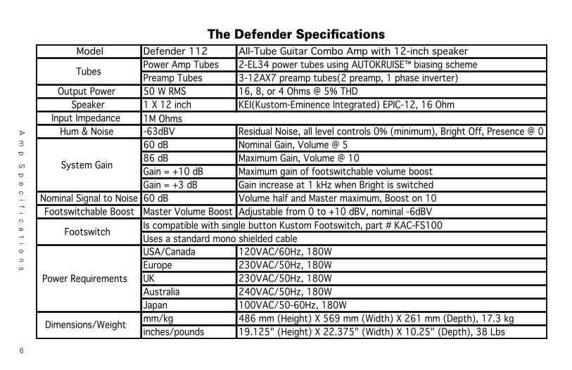
Model Defender 112 All-Tube Guitar Combo Amp with 12-inch speakerPower Amp Tubes 2-EL34 power tubes using AUTOKRUISE™ biasing schemePreamp Tubes 3-12AX7 preamp tubes(2 preamp, 1 phase inverter)
Output Power 50 W RMS 16, 8, or 4 Ohms @ 5% THDSpeaker 1 X 12 inch KEI(Kustom-Eminence Integrated) EPIC-12, 16 Ohm
Input ImpedanceHum & Noise -63dBV Residual Noise, all level controls 0% (minimum), Bright Off, Presence @ 0
60 dB Nominal Gain, Volume @ 586 dB Maximum Gain, Volume @ 10Gain = +10 dB Maximum gain of footswitchable volume boostGain = +3 dB Gain increase at 1 kHz when Bright is switched
Nominal Signal to Noise 60 dB Volume half and Master maximum, Boost on 10Footswitchable Boost Master Volume Boost Adjustable from 0 to +10 dBV, nominal -6dBV
USA/Canada 120VAC/60Hz, 180WEurope 230VAC/50Hz, 180WUK 230VAC/50Hz, 180WAustralia 240VAC/50Hz, 180WJapan 100VAC/50-60Hz, 180Wmm/kg 486 mm (Height) X 569 mm (Width) X 261 mm (Depth), 17.3 kginches/pounds 19.125" (Height) X 22.375" (Width) X 10.25" (Depth), 38 Lbs
1M Ohms
Tubes
Power Requirements
Footswitch
System Gain
Dimensions/Weight
Is compatible with single button Kustom Footswitch, part # KAC-FS100Uses a standard mono shielded cable
The Defender Specifications

7
Am
p
S
ig
na
l
P
at
h

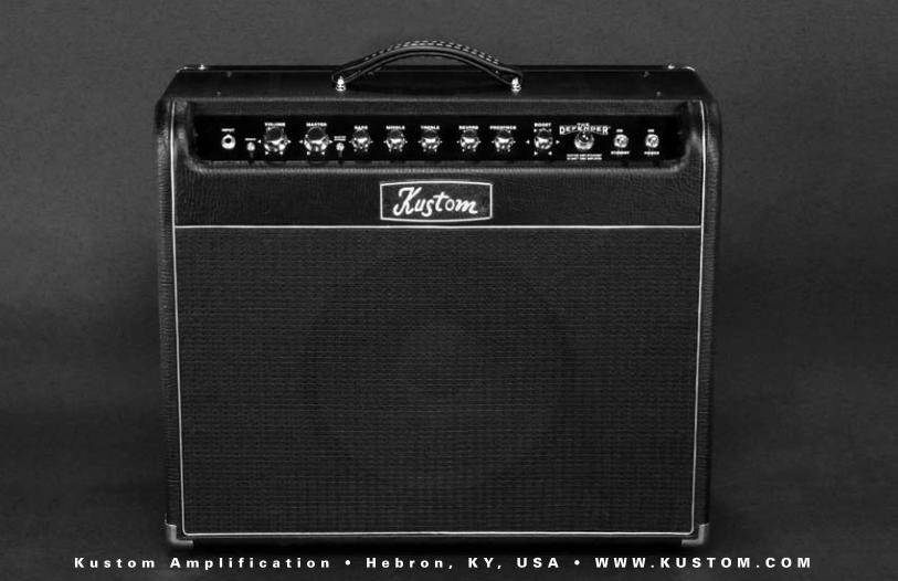
The Defender 112 Combo Control Panel
1) Input: This is a 1/4” 2-conductor input jack for plugging in your instru-ment. It is intended for guitar but will accept other instruments as well.
2) Bright: Flipping the Bright switch will increase the high frequencies of the signal, while also reducing low frequencies for a chunkier, tighter attack. This function is very useful for fine-tuning the amp’s tone and feel for different guitars.
3) Volume: This control adjusts the gain in the input stages of the pre-amp. Utilizing an exclusive new circuit called Duo-Mod™, it changes gain in multiple stages to allow a more variable range from clean to dirty than is typical of most tube guitar amps. This control is used in conjunction with the Master to adjust the amount of distortion and vol-ume. For cleaner sounds, adjust Volume to lower settings and the Mas-ter to higher settings. For slight breakup, the controls should be set in their middle ranges. For heavier distortion, set the Gain higher and the Master lower.
4) Master: The Master sets the overall volume and simultaneously tai-lors the tone controls to work better for that range. If the Master is set
higher, as it would be for cleaner sounds, then the tone is adjusted for cleaner, “chimey” tone. If the Master is set lower, as it would be for more distorted sounds, then the lows are increased for a fatter distor-tion tone that’s still tight sounding. The resulting system makes it easy to get a good tone without having to change the EQ settings.
5) Master Bypass: Non-master volume amps are something that vin-tage amp experts have always touted as being an essential element to great, “crank it up” tones. This switch will entirely disable the Master Volume control from the circuit to give you the penetrating tone and headroom of vintage, non-Master types of amplifiers.
6) Bass: This passive EQ adjusts the low frequency equalization of the amplifier. It interacts with the Middle and Treble as described in the Treble EQ section (8). For a tighter low end, use the Bass EQ set to lower settings. This is particularly helpful when using the amp at very loud settings.
7) Middle: This passive EQ adjusts the midrange equalization of the amplifier. It interacts with the Bass and Treble EQ as described in the
8
Th
e
De
fen
de
r C
on
trol
Pa
ne
ls

Treble EQ section (8). For a heavier, more distorted sound, set the Mid-dle lower. For more of a vintage-style, cleaner sound, set the Middle higher.
8) Treble: This passive EQ adjusts the high frequency equalization of the amplifier, but also interacts with the Bass and Middle controls as follows: As the Treble is increased, the Bass automatically decreases and the Middle slides down in frequency. Conversely, if the Treble is decreased, the Bass automatically increases and the Middle slides up in frequency. This interaction is typical of vintage-style passive EQ, and is responsible for the increased effectiveness of such a simple system.
9) Reverb: Reverb controls the amount of the reverberation effect in the amplifier. This effect is created by an authentic spring reverb pan and sounds essentially like playing the amp in a large room. The Reverb can be defeated by turning the control fully counter-clockwise.
10) Presence: The Presence control operates in the power amp section of the amp and adds high frequencies to the tone. Higher settings will provide more bite and help you cut through the mix.
11) Boost: The Boost knob controls the amount of footswitchable boost in the power amp, and is particularly useful for solos. It will provide up to 10dB of “Master Volume” boost. The tone is optimized to increase the volume without sacrificing too much headroom in the power amp, so the resulting solo cuts through. (Note: Boost is active if the foot-switch is unplugged.)
12) Jeweled Pilot Light: When lit, it indicates that the amplifier’s power switch is in the ON position.
13) Standby: This allows the amplifier to be powered up, but with the tubes in a non-operational mode. The Standby can be used instead of the power switch between performance sets, since it allows the amp to “shut down” while keeping the tubes warm and ready to go. It’s also best to power the amp up with this switch set to the downward “Off” position until the tubes have had a few minutes to warm up, although modern tubes are more tolerant of this.
14) ON Power: Provides AC power to the amplifier when in the upward “On” position.
9
Th
e
De
fen
de
r C
on
trol
Pa
ne
ls

The Defender 112 Combo Back Panel
1) Power Cord Receptacle/Fuse Holder: Insert the AC cord (pro-vided) firmly into the AC connector. NOTE: Replace the AC power cord if protective jacket is damaged or ground pin is damaged or removed. The fuse is located in a housing just below the receptacle. Replace only with same type and size. To remove the fuse, remove AC power cord and pull out on the tab above the fuse symbol locat-ed on the fuse carriage. Place the new fuse in the carriage clip and re-insert. NOTE: To prevent an electrical hazard, DO NOT replace fuse without using the fuse carriage. Replace the fuse carriage if lost or damaged before re-inserting the AC power cord.
2) Footswitch: The Footswitch jack on The Defender is a mono jack that connects a footswitch to the amplifier. The footswitch switches the Boost feature on and off.
3) Tube Charta. Bias Switch: The Defender ships from the factory with classic EL34 output tubes. However, if you happen to prefer 6L6s or just want to try something different, this amp has the ability. Under-neath the tube cage is a switch that may be used to change the bias to accommodate either EL34 or 6L6 power tubes. (Note: This switch is not a user serviceable item. Be sure to take it to a qualified service tech to make these changes.)
b. EL34 Output Tubes: These power tubes were selected to provide the best combination of performance and tube life, and shouldn’t require adjustment to their bias. The amp uses a mixed-bias sys-tem, which is a combination of fixed and self-bias techniques to give the user the best of both worlds. The result is that the amp will control its own bias to a certain point, but without the typical reduc-
10
Th
e
De
fen
de
r C
on
trol
Pa
ne
ls

tion in power associated with normal self-biased amp designs. The Defender uses two EL34s in a “push-pull” amplifier configuration.
c. Phase Inverter Tube: The phase inverter tube uses a single 12AX7 in what’s called a long-tail pair configuration. This results in the most signal swing possible for driving a power amp and the most symmetrical drive capability, as well.
d. Preamp Tube 2: This 12AX7 is used in boosting the gain and driv-ing the EQ. It has the biggest impact on higher gain sounds.
e. Preamp Tube 1: Half of this 12AX7 is the input tube, and as such, is the most likely to cause microphonic problems. If tube feedback oc-curs, it can usually be corrected by swapping this first tube with one of the other tube locations, since they have less gain following them and are less prone to feedback. The first tube also has the greatest effect on the “cleaned up” tone of the amp, i.e. the tone when the
guitar is turned down. The other half of this tube is responsible for providing the extra gain needed for the Boost control.
4 & 6) Speaker Outputs: These 1⁄4” jacks are provided to connect the internal and/or external speakers to The Defender. The amplifier should never be operated without a speaker plugged into a speaker jack.
5) Impedance Selector: This switch is used to select the appropriate impedance, and is important in achieving the desired results from The Defender. The correct impedance should be selected using the Impedance Selector Switch as follows:
a. Internal speaker only: 16 ohm settingb. Internal speaker + external 16 ohm speaker: 8 ohm settingc. Internal speaker + external 8 ohm speaker: 4 ohm setting, al-though it’s not matched.
11
Th
e
De
fen
de
r C
on
trol
Pa
ne
ls

12
Ac
ce
ss
or
ie
s KACCC36D - Amp cover to defend The Defender from dust and the elements. Features an em-broidered classic Kustom logo, top quality vinyl and piping.
FACFS100 - Footswitch for activating the adjust-able volume boost function on The Defender™. The Defender automatically will have the boost enabled at all times if no footswitch is plugged into the amp.
You can find these accessories through your local Kustom dealer!

K u s t o m A m p l i f i c a t i o n • H e b r o n , K Y , U S A • W W W . K U S T O M . C O M