Embed Size (px)
Citation preview
DJ Controller
MC2000Owner’s Manual

Before use
Part names and
functions Connections
Basic
operations Installing and setting up
supplied software
USB settings Troubleshooting
IndexSpecifications
Signal system chart
I
CAUTIONRISK OF ELECTRIC SHOCK
DO NOT OPEN
CAUTION: TO REDUCE THE RISK OF ELECTRIC SHOCK, DO NOT REMOVE COVER (OR BACK). NO USER-SERVICEABLE PARTS INSIDE. REFER SERVICING TO QUALIFIED SERVICE PERSONNEL.
The lightning flash with arrowhead symbol, within an equilateral triangle, is intended to alert the user to the presence of uninsulated “dangerous voltage” within the product’s enclosure that may be of sufficient magnitude to constitute a risk of electric shock to persons.
The exclamation point within an equilateral triangle is intended to alert the user to the presence of important operating and maintenance (servicing) instructions in the literature accompanying the appliance.
IMPORTANT TO SAFETYWARNING:To reduce the risk of fire and electric shock, this apparatus should not be exposed to rain or moisture and objects filled with liquids, such as vases, should not be placed on this apparatus.
CAUTION1. Do not open the top cover
In order to prevent electric shock, do not open the top cover.If problems occur, contact your DENON DEALER.
2. Do not place anything insideDo not place metal objects or spill liquid inside the system.Electric shock or malfunction may result.
Please, record and retain the Model name and serial number of your set shown on the rating label.
Model No. MC2000Serial No.
FCC INFORMATION (For US customers)
1. COMPLIANCE INFORMATIONProduct Name: Professional DJ ControllerModel Number: MC2000This product complies with Part 15 of the FCC Rules. Operation is subject to the following two conditions: (1) this product may not cause harmful interference, and (2) this product must accept any interference received, including interference that may cause undesired operation.
Denon Professional div. D&M Professional1100 Maplewood Drive Itasca, IL 60143
Tel. 630-741-0330
2. IMPORTANT NOTICE: DO NOT MODIFY THIS PRODUCT This product, when installed as indicated in the instructions contained in this manual, meets FCC requirements. Modification not expressly approved by DENON may void your authority, granted by the FCC, to use the product.
3. NOTEThis product has been tested and found to comply with the limits for a Class B digital device, pursuant to Part 15 of the FCC Rules. These limits are designed to provide reasonable protection against harmful interference in a residential installation.This product generates, uses and can radiate radio frequency energy and, if not installed and used in accordance with the instructions, may cause harmful interference to radio communications. However, there is no guarantee that interference will not occur in a particular installation. If this product does cause harmful interference to radio or television reception, which can be determined by turning the product OFF and ON, the user is encouraged to try to correct the interference by one or more of the following measures:
• Reorientorrelocatethereceivingantenna.• Increasetheseparationbetweentheequipmentandreceiver.• Connect the product into an outlet on a circuit different from that to which the receiver is
connected.• Consult the local retailer authorized to distribute this typeof product or an experienced radio/TV
technician for help.
For Canadian customers:This Class B apparatus complies with Canadian ICES-003.Cet appareil numérique de la classe B est conforme à la norme NMB-003 du Canada.

Before use
Part names and
functions Connections
Basic
operations Installing and setting up
supplied software
USB settings Troubleshooting
IndexSpecifications
Signal system chart
II
IMPORTANT SAFETY INSTRUCTIONSREAD BEFORE OPERATING EQUIPMENT
This product was designed and manufactured to meet strict quality and safety standards. There are, however, some installation and operation precautions which you should be particularly aware of.
1. Read these instructions.
2. Keep these instructions.
3. Heed all warnings.
4. Follow all instructions.
5. Do not use this apparatus near water.
6. Clean only with dry cloth.
7. Do not install near any heat sources such as radiators, heat registers, stoves, or other apparatus (including amplifiers) that produce heat.
8. Onlyuseattachments/accessoriesspecifiedbythemanufacturer.
9. Use only with the cart, stand, tripod, bracket, or table specified by the manufacturer, or sold with the apparatus. When a cart is used, use caution whenmovingthecart/apparatuscombinationtoavoidinjuryfromtip-over.
10. Refer all servicing to qualified service personnel. Servicing is required when the apparatus has been damaged in any way, such as power-supply cord or plug is damaged, liquid has been spilled or objects have fallen into the apparatus, the apparatus has been exposed to rain or moisture, does not operate normally, or has been dropped.

Before use
Part names and
functions Connections
Basic
operations Installing and setting up
supplied software
USB settings Troubleshooting
IndexSpecifications
Signal system chart
III
n NOTE ON USE/HINWEISE ZUM GEBRAUCH/OBSERVATIONS RELATIVES A L’UTILISATION/ NOTE SULL’USO/NOTAS SOBRE EL USO/ALVORENS TE GEBRUIKEN/OBSERVERA
WARNINGS WARNHINWEISE AVERTISSEMENTS AVVERTENZE ADVERTENCIAS WAARSCHUWINGEN VARNINGAR•Keep the unit free from
moisture, water, and dust.•Do not let foreign objects into
the unit.•Do not let insecticides, benzene,andthinnercomeincontact with the unit.
•Never disassemble or modify the unit in any way.
•Naked flame sources such as lighted candles should not be placed on the unit.
•Do not expose the unit to dripping or splashing fluids.
•Do not place objects filled with liquids, such as vases, on the unit.
•Gehen Sie vorsichtig mit dem Netzkabelum.Halten Sie das Kabel am Stecker, wenn Sie den Stecker herausziehen.
•Halten Sie das Gerät von Feuchtigkeit, Wasser und Staub fern.
•Wenn das Gerät längere Zeit nicht verwendet werden soll, trennenSiedasNetzkabelvomNetzstecker.
•Lassen Sie keine fremden Gegenstände in das Gerät kommen.
•Lassen Sie das Gerät nicht mitInsektiziden,BenzinoderVerdünnungsmittelninBerührungkommen.
•VersuchenSieniemalsdasGerätauseinanderzunehmenoderzuverändern.
•Auf dem Gerät sollten keinerlei direkte Feuerquellen wie beispielsweiseangezündeteKerzenaufgestelltwerden.
•Das Gerät sollte keiner tropfenden oderspritzendenFlüssigkeitausgesetztwerden.
•Auf dem Gerät sollten keine mit FlüssigkeitgefülltenBehälterwiebeispielsweiseVasenaufgestelltwerden.
•DasNetzkabelnichtmitfeuchtenoder nassen Händen anfassen.
•Wenn der Schalter ausgeschaltet ist (OFF-Position), ist das Gerät nichtvollständigvomStromnetz(MAINS) abgetrennt.
•Das Gerät sollte in der Nähe einer Netzsteckdoseaufgestelltwerden,damitesleichtandasStromnetzangeschlossen werden kann.
•Manipuler le cordon d’alimentation avec précaution.Tenir la prise lors du débranchement du cordon.
•Protéger l’appareil contre l’humidité, l’eau et la poussière.
•Débrancher le cordon d’alimentation lorsque l’appareil n’est pas utilisé pendant de longues périodes.
•Ne pas laisser des objets étrangers dans l’appareil.
•Ne pas mettre en contact des insecticides,dubenzèneetundiluant avec l’appareil.
•Ne jamais démonter ou modifier l’appareil d’une manière ou d’une autre.
•Ne jamais placer de flamme nue sur l'appareil, notamment des bougies allumées.
•L’appareil ne doit pas être exposé à l’eau ou à l’humidité.
•Ne pas poser d’objet contenant du liquide, par exemple un vase, sur l’appareil.
•Ne pas manipuler le cordon d’alimentation avec les mains mouillées.
•Lorsque l’interrupteur est sur la position OFF, l’appareil n’est pas complètement déconnecté du SECTEUR (MAINS).
•L’appareil sera installé près de la source d’alimentation, de sorte que cette dernière soit facilement accessible.
•Manneggiate il cavo di alimentazioneconattenzione.Tenete ferma la spina quando scollegate il cavo dalla presa.
•Tenete l’unità lontana dall’umidità, dall’acqua e dalla polvere.
•Scollegate il cavo di alimentazionequandoprevedetedinonutilizzarel’unità per un lungo periodo di tempo.
•Non inserite corpi estranei all’interno dell’unità.
•Assicuratevi che l’unità non entri in contatto con insetticidi, benzoloosolventi.
•Non smontate né modificate l’unità in alcun modo.
•Nonposizionatesull’unitàfiamme libere, come ad esempio candele accese.
•L’apparecchiatura non deve essere esposta a gocciolii o spruzzi.
•Nonposizionatesull’unitàalcunoggetto contenente liquidi, come ad esempio i vasi.
•Non toccare il cavo di alimentazioneconlemanibagnate.
•Quando l’interruttore ènellaposizioneOFF,l’apparecchiatura non è completamente scollegata da MAINS.
•L’apparecchio va installato in prossimità della fonte di alimentazione,inmodochequest’ultima sia facilmente accessibile.
•Maneje el cordón de energía con cuidado.Sostenga el enchufe cuando desconecte el cordón de energía.
•Mantenga el equipo libre de humedad, agua y polvo.
•Desconecte el cordón de energía cuando no utilice el equipo por mucho tiempo.
•No deje objetos extraños dentro del equipo.
•No permita el contacto de insecticidas, gasolina y diluyentes con el equipo.
•Nunca desarme o modifique el equipo de ninguna manera.
•No deberán colocarse sobre el aparato fuentes inflamables sin protección, como velas encendidas.
•No exponer el aparato al goteo o salpicaduras cuando se utilice.
•No colocar sobre el aparato objetos llenos de líquido, como jarros.
•No maneje el cable de alimentación con las manos mojadas.
•Cuando el interruptor está en la posición OFF, el equipo no está completamente desconectado de la alimentación MAINS.
•El equipo se instalará cerca de la fuente de alimentación de manera que resulte fácil acceder a ella.
•Hanteer het netsnoer voorzichtig.Houd het snoer bij de stekker vastwanneerdezemoetworden aan- of losgekoppeld.
•Laat geen vochtigheid, water of stof in het apparaat binnendringen.
•Neem altijd het netsnoer uit het stopkontakt wanneer het apparaat gedurende een lange periode niet wordt gebruikt.
•Laat geen vreemde voorwerpen in dit apparaat vallen.
•Voorkomdatinsecticiden,benzeenofverfverdunnermetdit toestel in contact komen.
•Dit toestel mag niet gedemonteerd of aangepast worden.
•Plaats geen open vlammen, bijvoorbeeld een brandende kaars, op het apparaat.
•Stel het apparaat niet bloot aan druppels of spatten.
•Plaats geen voorwerpen gevuld met water, bijvoorbeeld een vaas, op het apparaat.
•Raak het netsnoer niet met natte handen aan.
•Als de schakelaar op OFF staat, is het apparaat niet volledig losgekoppeld van de netspanning (MAINS).
•De apparatuur wordt in de buurt van het stopcontact geïnstalleerd,zodatditaltijdgemakkelijk toegankelijk is.
•Hantera nätkabeln varsamt.Håll i kabeln när den kopplas från el-uttaget.
•Utsätt inte apparaten för fukt, vatten och damm.
•Koppla loss nätkabeln om apparaten inte kommer att användas i lång tid.
•Se till att främmande föremål inte tränger in i apparaten.
•Se till att inte insektsmedel på spraybruk, bensen och thinner kommer i kontakt med apparatens hölje.
•Ta inte isär apparaten och försök inte bygga om den.
•Placera inte öppen eld, t.ex. tända ljus, på apparaten.
•Apparaten får inte utsättas för vätska.
•Placera inte föremål fyllda med vätska, t.ex. vaser, på apparaten.
•Hantera inte nätsladden med våta händer.
•Även om strömbrytaren står i det avstängda läget OFF, så är utrustningen inte helt bortkopplad från det elektriska nätet (MAINS).
•Utrustningen ska vara installerad nära strömuttaget så att strömförsörjningen är lätt att tillgå.
Before use
Part names and
functions Connections
Basic
operations Installing and setting up
supplied software
USB settings Troubleshooting
IndexSpecifications
Signal system chart
IV
•DECLARATION OF CONFORMITY (English) We declare under our sole responsibility that this product, to which this declaration relates, is
in conformity with the following standards: EN55022, EN55024, EN61000-3-2 and EN61000-3-3. FollowingtheprovisionsofEMCDirective2004/108/EC,theECregulation1275/2008anditsframeworkDirective2009/125/ECforEnergy-relatedProducts(ErP).
•ÜBEREINSTIMMUNGSERKLÄRUNG (Deutsch) Wir erklärenunter unsererVerantwortung, daßdiesesProdukt, auf das sichdieseErklärungbezieht,denfolgendenStandardsentspricht:
EN55022, EN55024, EN61000-3-2 und EN61000-3-3. Gemäß den Bestimmungen der EMV Richtlinie 2004/108/EG, der Verordnung(EG) Nr. 1275/2008 der Kommission und deren Rahmenrichtlinie 2009/125/EG zuenergieverbrauchsrelevanten Produkten (ErP).
•DECLARATION DE CONFORMITE (Français) Nous déclarons sous notre seule responsabilité que l’appareil, auquel se réfère cette
déclaration, est conforme aux standards suivants: EN55022, EN55024, EN61000-3-2 et EN61000-3-3. SelonladirectiveCEM2004/108/EC,laréglementationeuropéenne1275/2008et ladirective2009/125/ECétablissantuncadredetravailapplicableauxproduitsliésàl’énergie(ErP).
•DICHIARAZIONE DI CONFORMITÀ (Italiano) Dichiariamo con piena responsabilità che questo prodotto, al quale la nostra dichiarazione si
riferisce, è conforme alle seguenti normative: EN55022, EN55024, EN61000-3-2 e EN61000-3-3. FacendoseguitoalledisposizionidelladirettivaEMC2004/108/EC,allanormaEC1275/2008eallarelativaleggequadro2009/125/ECinmateriadiprodottialimentatiadenergia(ErP).
QUESTO PRODOTTO E’ CONFORME ALD.M.28/08/95N.548
•DECLARACIÓN DE CONFORMIDAD (Español) Declaramos bajo nuestra exclusiva responsabilidad que este producto al que hace referencia
esta declaración, está conforme con los siguientes estándares: EN55022, EN55024, EN61000-3-2 y EN61000-3-3. De acuerdo con la directiva CEM 2004/108/CE, la normativa CE 1275/2008 y su directivamarco2009/125/ECparaproductosrelacionadosconlaenergía(ErP).
•EENVORMIGHEIDSVERKLARING (Nederlands) Wijverklarenuitsluitendoponzeverantwoordelijkheiddatditprodukt,waaropdezeverklaring
betrekking heeft, in overeenstemming is met de volgende normen: EN55022, EN55024, EN61000-3-2 en EN61000-3-3. Volgens de voorzieningen van EMC-richtlijn 2004/108/EC, de EU-richtlijn 1275/2008 en dekaderrichtlijn2009/125/ECvoorenergieverbruikendeproducten(ErP).
•ÖVERENSSTÄMMELSESINTYG (Svenska) Härmed intygas helt på eget ansvar att denna produkt, vilken detta intyg avser, uppfyller
följande standarder: EN55022, EN55024, EN61000-3-2 och EN61000-3-3. Uppfyller reglerna i EMC-direktivet 2004/108/EC, EU-förordningen 1275/2008 ochramverksdirektivet2009/125/ECförenergirelateradeprodukter(ErP).
D&M Professional EuropeA division of D&M Europe B.V.Beemdstraat 115653 MA EindhovenThe Netherlands

Before use
Part names and
functions Connections
Basic
operations Installing and setting up
supplied software
USB settings Troubleshooting
IndexSpecifications
Signal system chart
V
A NOTE ABOUT RECYCLING:This product’s packaging materials are recyclable and can be reused. Please dispose of any materials in accordance with the local recycling regulations.When discarding the unit, comply with local rules or regulations.Batteries should never be thrown away or incinerated but disposed of in accordance with the local regulations concerning battery disposal.This product and the supplied accessories, excluding the batteries, constitute the applicable product according to the WEEE directive.
HINWEIS ZUM RECYCLING:Das Verpackungsmaterial dieses Produktes ist zum Recyceln geeignet und kann wiederverwendet werden. Bitte entsorgen Sie alle Materialien entsprechend der örtlichen Recycling-Vorschriften.BeachtenSiebeiderEntsorgungdesGerätesdieörtlichenVorschriftenundBestimmungen.DieBatteriendürfennichtindenHausmüllgeworfenoderverbranntwerden;bitteentsorgenSiedieBatteriengemäßderörtlichenVorschriften.Dieses Produkt und das im Lieferumfang enthaltene Zubehör (mit Ausnahme der Batterien!) entsprechen der WEEE-Direktive.
UNE REMARQUE CONCERNANT LE RECYCLAGE:Lesmatériauxd’emballagedeceproduitsontrecyclablesetpeuventêtreréutilisés.Veuillezdisposerdes matériaux conformément aux lois sur le recyclage en vigueur.Lorsquevousmettezcetappareilaurebut,respectezlesloisouréglementationsenvigueur.Les piles ne doivent jamais être jetées ou incinérées, mais mises au rebut conformément aux lois en vigueur sur la mise au rebut des piles.Ce produit et les accessoires inclus, à l’exception des piles, sont des produits conformes à la directive DEEE.
NOTA RELATIVA AL RICICLAGGIO:Imateriali di imballaggio di questoprodotto sono riutilizzabili e riciclabili. Smaltire imateriali conformemente allenormative locali sul riciclaggio.Per lo smaltimento dell’unità, osservare le normative o le leggi locali in vigore.Non gettare le batterie, né incenerirle, ma smaltirle conformemente alla normativa locale sui rifiuti chimici.Questoprodottoegliaccessoriinclusinell’imballaggiosonoapplicabilialladirettivaRAEE,adeccezionedellebatterie.
ACERCA DEL RECICLAJE:Losmateriales de embalaje de este producto son reciclables y se pueden volver a utilizar. Disponga de estosmateriales siguiendo los reglamentos de reciclaje de su localidad. Cuando se deshaga de la unidad, cumpla con las reglas o reglamentos locales. Las pilas nunca deberán tirarse ni incinerarse. Deberá disponer de ellas siguiendo los reglamentos de su localidad relacionados con los desperdicios químicos.Este producto junto con los accesorios empaquetados es el producto aplicable a la directiva RAEE excepto pilas.
EEN AANTEKENING MET BETREKKING TOT DE RECYCLING:Hetinpakmateriaalvanditproductisrecycleerbaarenkanopnieuwgebruiktworden.Erwordtverzochtomzichvanelk afvalmateriaal te ontdoen volgens de plaatselijke voorschriften. Volgvoorhetwegdoenvandespelerdevoorschriftenvoordeverwijderingvanwit-enbruingoedop.Batterijen mogen nooit worden weggegooid of verbrand, maar moeten volgens de plaatselijke voorschriften betreffende chemisch afval worden verwijderd.Op dit product en de meegeleverde accessoires, m.u.v. de batterijen is de richtlijn voor afgedankte elektrische en elektronische apparaten (WEEE) van toepassing.
OBSERVERA ANGÅENDE ÅTERVINNING:Produktens emballage är återvinningsbart och kan återanvändas. Kassera det enligt lokala återvinningsbestämmelser.När du kasserar enheten ska du göra det i överensstämmelse med lokala regler och bestämmelser.Batterier får absolut inte kastas i soporna eller brännas. Kassera dem enligt lokala bestämmelser för kemiskt avfall.Denna apparat och de tillbehör som levereras med den uppfyller gällande WEEE-direktiv, med undantag av batterierna.

1
Part names and
functions Connections
Basic
operations Installing and setting up
supplied software
USB settings Troubleshooting
IndexSpecifications
Signal system chart
Before use
Before use
Before use ·················································································1
Contents
Accessories ····················································································2About this manual ········································································2Features ·························································································2Cautions on handling ····································································3
Connections ·············································································4
Preparations ··················································································4Cables used for connection ··························································4
Input terminal connection ····························································4Connectingamicrophone/externaldevices ··································4
Output terminal connections ·······················································4Outputtingtoanamplifier/poweredspeakersandrecordingdevices ·························································································4
Connecting to a computer ···························································5
Installing and setting up supplied software ············6
Installing the ASIO driver (Windows only) ·································6Starting up ····················································································8About the control panel screen·····················································8
Installing SERATO DJ INTRO ·······················································9Installation onto a Mac computer ·················································9Installation onto a Windows computer ·········································9
Basic operation ·····································································10
Basic operation ············································································10Turning the power on ·································································10Turning the power off ·································································10
Microphone input ········································································10Adjusting the microphone input level ·········································10
Line input ·····················································································10Adjusting the line input level ······················································10
Headphone monitor ····································································10Adjusting the sensitivity of the touch sensor ··························11SHIFT lock function ·····································································12
Locking SHIFT·············································································12Cancelling SHIFT lock ·································································12
USB settings ··········································································12
USB AUDIO Input ········································································12MIDI command input/output ·····················································13
Setting the MIDI command transmission interval time ··············13MIDI command list ····································································14
Part names and functions ···············································17
Top panel ·····················································································17Front panel ···················································································20Rear panel ····················································································20
Troubleshooting···································································21
Specifications ········································································21
Index ··························································································22
Signal system chart····························································23
2
Part names and
functions Connections
Basic
operations Installing and setting up
supplied software
USB settings Troubleshooting
IndexSpecifications
Signal system chart
Before use
Features1. Reliable design•Adopted high-grade steel cabinet and self-lighting buttons.•Equipped with line input that can be connected to a device such as
a CD player etc. (vpage 10).
2. USB MIDI controller•Equipped with a physical controller function that controls DJ
software.•Simple, easy to understand design layout that provides optimum
control of SERATO DJ INTRO.•Equipped with a touch sense function compatible jog wheel. •EquippedwithlargeCUE/PLAYbuttonsthatcanbepressedeasily.•EquippedwiththeSYNCbuttonthatcanimmediatelysynchronize
beats for two decks.•Separate FX controls for individual decks.
3. USB AUDIO interface•High sound quality design that supports sampling frequency of 48 kHz.
•Supports USB audio input (stereo 2 inputs)•Supplied with ASIO drivers for low latency (vpage 6).
4. Others•Equipped with a microphone input terminal.•Supports USB bus power. Can be used simply by connecting this
device to a computer using a USB cable.•Compact sides provide a useful, easy-to-carry design.•Supplied with DJ software (SERATO DJ INTRO)
In the following cases, this unit may not operate by USB bus power supply:•USB power supply capacity on the computer is lower than what
is specified.•Other USB devices are connected to the computer.•Headphones with impedance less than 40 Ω are connected to this
unit..
About this manual nSymbols
v This symbol indicates a reference page on which related information is described.
This symbol indicates a supplementary information and tips for operations.
NOTEThis symbol indicates points to remember operations or function limitations.
n IllustrationsNote that the illustrations in these instructions are for explanation purposes and may differ from the actual unit.
AccessoriesCheck that the following parts are supplied with the product.
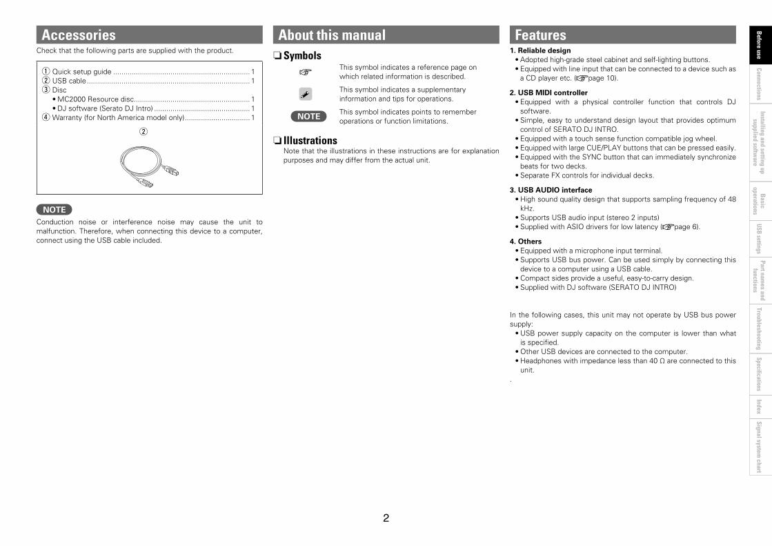
q Quick setup guide ................................................................... 1w USB cable ................................................................................ 1e Disc
•MC2000 Resource disc......................................................... 1•DJ software (Serato DJ Intro) ............................................... 1
r Warranty (for North America model only) ................................ 1
rw
NOTEConduction noise or interference noise may cause the unit to malfunction. Therefore, when connecting this device to a computer, connect using the USB cable included.

3
Part names and
functions Connections
Basic
operations Installing and setting up
supplied software
USB settings Troubleshooting
IndexSpecifications
Signal system chart
Before use
Cautions on handling•About condensation
If there is a major difference in temperature between the inside of the unit and the surroundings, condensation (dew) may form on the operating parts inside the unit, causing the unit not to operate properly.If this happens, let the unit sit for an hour or two with the power turned off and wait until there is little difference in temperature before using the unit.
•Cautions on using mobile phonesUsing a mobile phone near this unit may result in noise. If that occurs, move the mobile phone away from this unit when it is in use.
•About care•Wipe the cabinet and control panel clean with a soft cloth.•Follow the instructions when using a chemical cleaner.•Benzene, paint thinner or other organic solvents as well as
insecticide may cause material changes and discoloration if brought into contact with the unit, and should therefore not be used.
This is a class B electronic device.This product is designed for residential or home use. However, radio interference may occur when it is used near equipment that receives radio or television signals. Be sure to follow the instructions in the owner’s manual and use the device correctly.
VCCI-B
4
Before use
Part names and
functions B
asic operations
Installing and setting up supplied softw
areUSB settings
Troubleshooting Index
Specifications Signal system
chart Connections
NOTE•Do not connect this device to the PC using the USB cable until all
other connections with external devices are completed.•When making connections, also refer to the operating instructions of
the other components.•Insert the plugs securely. Loose connections will result in abnormal
and undesired operation.•Be sure to connect the left and right channels properly (left with left,
right with right).•Connect the cables to the correct input and output terminals.•Do not bundle the USB cable together with connection cables to
other external devices. Doing so will result in the generation of noise.
PreparationsCables used for connectionSelect the cables according to the equipment being connected.
n For RCA input/output terminals
R
L
R
L
RCA pin plug cable (sold separately)
n For USB terminal
USB cable (supplied)
n For microphone input
1/4"TRSorTSmaletoXLRfemale(soldseparately)
Connections
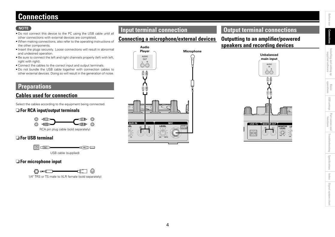
Input terminal connectionConnecting a microphone/external devices
RL
RL
RL
AUDIOOUT
Audio Player Microphone
Output terminal connectionsOutputting to an amplifier/powered speakers and recording devices
RL
RL
RL
AUDIOIN
Unbalanced main input
5
Before use
Part names and
functions B
asic operations
Installing and setting up supplied softw
areUSB settings
Troubleshooting Index
Specifications Signal system
chart Connections
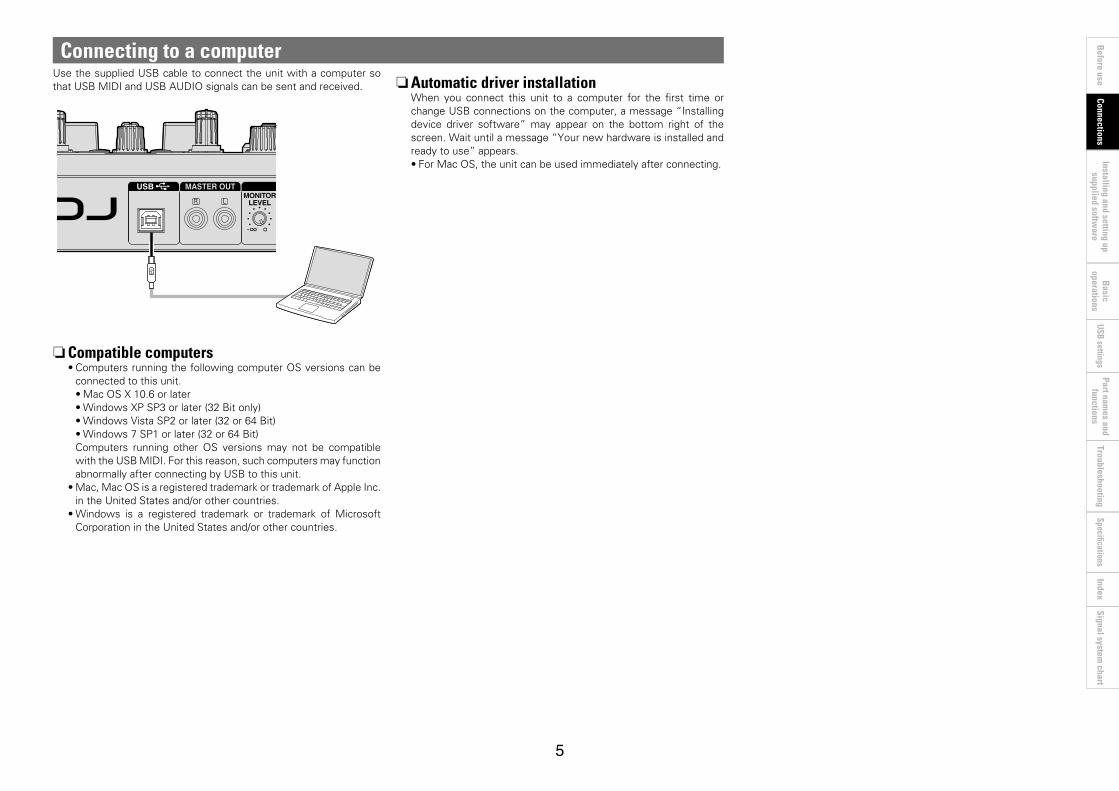
Connecting to a computer Use the supplied USB cable to connect the unit with a computer so that USB MIDI and USB AUDIO signals can be sent and received.
nCompatible computers•Computers running the following computer OS versions can be
connected to this unit.•Mac OS X 10.6 or later•Windows XP SP3 or later (32 Bit only)•WindowsVistaSP2orlater(32or64Bit)•Windows 7 SP1 or later (32 or 64 Bit)Computers running other OS versions may not be compatible with the USB MIDI. For this reason, such computers may function abnormally after connecting by USB to this unit.
•Mac, Mac OS is a registered trademark or trademark of Apple Inc. intheUnitedStatesand/orothercountries.
•Windows is a registered trademark or trademark of Microsoft CorporationintheUnitedStatesand/orothercountries.
nAutomatic driver installationWhen you connect this unit to a computer for the first time or change USB connections on the computer, a message “Installing device driver software” may appear on the bottom right of the screen.Waituntilamessage“Yournewhardwareisinstalledandready to use” appears.•For Mac OS, the unit can be used immediately after connecting.

6
Before use
Part names and
functions Connections
Basic
operations USB settings
Troubleshooting Index
Specifications Signal system
chart Installing and setting up
supplied software
Installing and setting up supplied software
1 Insert the supplied “MC2000 Resource Disc” into the computer.The browse screen for the disc drive is displayed.
•If the browse screen is not displayed, click the disc drive on My Computer.
2 Click “Asio Driver Installation”.TheASIODriverSetupWizardislaunched.Click “Next >”.
The InstallShield(R) Wizard will install DENON DJ ASIO for DJController on your computer. to continue, click Next.
WARNING: This program is protected by copyright law andinternational treaties.
Welcome to the InstallShield Wizard forDENON DJ ASIO for DJ Controller
DENON DJ ASIO for DJ Controller - InstallShield Wizard
Cancel Next >< Back< Back
3 The license agreement screen appears. If you agree, select “I accept the terms in the license agreement”.The “Next >” can now be selected.Click “Next >”.
I accept the terms in the license agreement
I do not accept the terms in the license agreement
SOFTWARE LICENSE AGREEMENT
NOTICE TO USER: Please read this Agreement carefully. By installing and usingall or any portion of the software(“Software”)supplied by D&M Holdings Inc(“D&M”), you accept all the terms and conditions of this Agreement. You agree that this agreement is enforceable like any written negotiated agreement signed by you.This Agreement is enforceable against you and any person or legal entity thatobtained the software and on whose behalf it is used. If you do not agree, do not installor use this Software.
D&M is the legal owner to all the intellectual property embedded,embodied and
InstallShieldInstallShield
DENON DJ ASIO for DJ Controller - InstallShield Wizard
Cancel
< Back Next >
Please read the following license agreement carefully.License Agreement
4 A screen for verifying the folder in which the ASIO driver is to be installed appears.Click “Next >”.
InstallShieldInstallShield
Install DENON DJ ASIO for DJ Controller to:C:¥Program Files¥DENON_DJ¥DDJCTRASIO¥
DENON DJ ASIO for DJ Controller - InstallShield Wizard
Cancel
Change...
< Back Next >
Click Next to install to this folder, or click Change toinstall to a different folder.
Destination Folder
By default, the ASIO driver is installed in “C\Program Files\DENON_DJ\DDJCTRASIO\”.To change this location, click “Change” and select a different folder.
Installing the ASIO driver (Windows only)If you're using this product with a MAC please proceed directly to page 9. UsethefollowingstepstoinstallthesuppliedASIOdrivers.Wheninstallingoruninstallingthedriversoftware,theadministrativeauthorizationofthecomputerisrequired.Logonasanadministratorofthecomputer,and execute the installation.ThesuppliedASIOdriversarefortheexclusiveuseonDENONDJcontrollers.AvailableonDN-MC6000/MC3000/MC2000models.•When using a Mac, no installation is required.
7
Before use
Part names and
functions Connections
Basic
operations USB settings
Troubleshooting Index
Specifications Signal system
chart Installing and setting up
supplied software
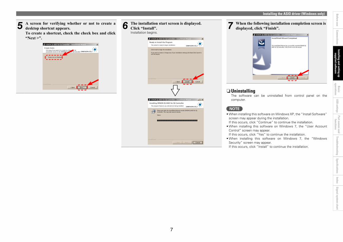
5 A screen for verifying whether or not to create a desktop shortcut appears.To create a shortcut, check the check box and click “Next >”.
Create icon on Desktop
InstallShieldInstallShield
DENON DJ ASIO for DJ Controller - InstallShield Wizard
Cancel< Back Next >
Tell setup if you want it to create to a few icons forconvenient access to the DENON DJ ASIO for DJ Controller
Create Icons
6 The installation start screen is displayed. Click “Install”.Installation begins.
The wizard is ready to begin installation.
InstallShieldInstallShield
Click Install to begin the installation.
If you want to review or change any of your installation settings,click Back.Click Cancel toexit the wizard.
Ready to Install the Program
DENON DJ ASIO for DJ Controller - InstallShield Wizard
Install Cancel< Back
The program features you selected are being installed.
InstallShieldInstallShield
Please wait while the InstallShield Wizard installs DENON DJ ASIO for DJController, This may take several minutes.
Status:
Installing DENON DJ ASIO for DJ Controller
DENON DJ ASIO for DJ Controller - InstallShield Wizard
Cancel< Back< Back Next > Next >
Installing the ASIO driver (Windows only)
7 When the following installation completion screen is displayed, click “Finish”.
The InstallShield Wizard has successfully installed DENON DJASIO for DJ Controller, Click Finish to exit the wizard.
InstallShield Wizard Completed
DENON DJ ASIO for DJ Controller - InstallShield Wizard
Cancel< Back< Back Finish Cancel
nUninstallingThe software can be uninstalled from control panel on the computer.
NOTE•When installing this software on Windows XP, the “Install Software”
screen may appear during the installation. If this occurs, click “Continue” to continue the installation.
•When installing this software on Windows 7, the “User Account Control” screen may appear. Ifthisoccurs,click“Yes”tocontinuetheinstallation.
•When installing this software on Windows 7, the “Windows Security” screen may appear. If this occurs, click “Install” to continue the installation.

8
Before use
Part names and
functions Connections
Basic
operations USB settings
Troubleshooting Index
Specifications Signal system
chart Installing and setting up
supplied software
Starting upWhen the DENON DJ ASIO driver “ASIO Control Panel” is opened from the DJ software or desktop icon, the MC2000 appears in the ASIO Control Panel.
About the control panel screen
OK
Disable
Cancel
Device DescriptionDevice Name:Unit Number.Software Version:Audio input channels:Audio output channels:Sampling frequency:Bit resolution:Audio buffer size:
Audio Buffer Size512sample(10ms)
MC20001-0448.0 kHz16 bit512
Devices
48.0kHz
16 bit24 bit
44.1kHz
88.2kHz96.0kHz
Sampling Rate
Bit Resolution
DENON DJ ASIO for DJ Controller Ver.1.0.0
MC2000
u y
rew tq
When using the DJ software, close this control panel screen.
Installing the ASIO driver (Windows only)
q Devices (Device list)This window is used for automatically displaying all connected DENON DJ devices in a list.(Example: MC2000)•When you select a device you want to set from
this list, the current settings of the selected device appear in a window u (“Device Description”).
•If you double-click a device, the ASIO device status is switched from “Enable” to “Disable” or vice versa.
•ASIO device status
Enable : A check mark appears on the left side of a device name and the name is highlighted (bold).
Disable : The check mark on the left side of a device name is removed and the device name is displayed in lightface.
•Youcanselectonedeviceatatime.•Youcansetmultipledevicestoenableatthe
same time.
w Enable/DisableThis button is used for switching a device selected in q (Devices) to enable or disable as an ASIO device.•When only one device is connected to the
computer, “Enable” is always selected.
The ASIO device status can also be switched by double-clicking the device name displayed in q (Devices).
e Audio Buffer SizeUsethisslidertoadjustthebuffersize.
NOTE•The range of values is 88 to 2048 (sample units),
in steps of 1 sample.•When you set multiple devices to enable as ASIO
devices, the same setting values apply to all ASIO devices.
r OK/CancelOK:Use this button to close the ASIO control panel, reflecting the changes to the settings.Cancel:Use this button to close the ASIO control panel without reflecting the changes to the settings.
t Bit ResolutionSelected bit resolution is displayed.
y Sampling RateThe sampling rate selection is displayed here.The frequencies with which the DENON DJ ASIO driver is compatible are as follows:•44.1kHz/48kHz/88.2kHz/96kHz•Thisdeviceonlysupports48kHz.
u Device DescriptionThis is the area in which information for the device selected in the device information list is displayed.The following are displayed:•Device Name•Unit Number•SoftwareVersion
(not available with this model)•Audio input channels•Audio output channels•Sampling frequency•Bitresolution(quantizationbitrate)•Audiobuffersize
NOTEIf the device’s information cannot be acquired, “–” (hyphens) are displayed for all items.
9
Before use
Part names and
functions Connections
Basic
operations USB settings
Troubleshooting Index
Specifications Signal system
chart Installing and setting up
supplied software
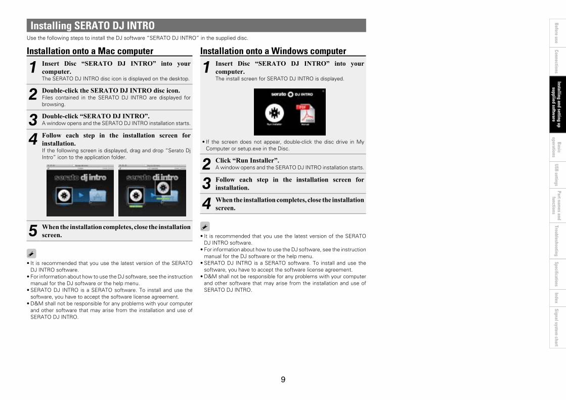
Installation onto a Windows computer
1 Insert Disc “SERATO DJ INTRO” into your computer.The install screen for SERATO DJ INTRO is displayed.
•If the screen does not appear, double-click the disc drive in My Computer or setup.exe in the Disc.
2 Click “Run Installer”.A window opens and the SERATO DJ INTRO installation starts.
3 Follow each step in the installation screen for installation.
4 When the installation completes, close the installation screen.
•It is recommended that you use the latest version of the SERATO DJ INTRO software.
•For information about how to use the DJ software, see the instruction manual for the DJ software or the help menu.
•SERATO DJ INTRO is a SERATO software. To install and use the software, you have to accept the software license agreement.
•D&M shall not be responsible for any problems with your computer and other software that may arise from the installation and use of SERATO DJ INTRO.
Installing SERATO DJ INTROUse the following steps to install the DJ software “SERATO DJ INTRO” in the supplied disc.
Installation onto a Mac computer
1 Insert Disc “SERATO DJ INTRO” into your computer.The SERATO DJ INTRO disc icon is displayed on the desktop.
2 Double-click the SERATO DJ INTRO disc icon.Files contained in the SERATO DJ INTRO are displayed for browsing.
3 Double-click “SERATO DJ INTRO”.A window opens and the SERATO DJ INTRO installation starts.
4 Follow each step in the installation screen for installation.If the following screen is displayed, drag and drop “Serato Dj Intro” icon to the application folder.
5 When the installation completes, close the installation screen.
•It is recommended that you use the latest version of the SERATO DJ INTRO software.
•For information about how to use the DJ software, see the instruction manual for the DJ software or the help menu.
•SERATO DJ INTRO is a SERATO software. To install and use the software, you have to accept the software license agreement.
•D&M shall not be responsible for any problems with your computer and other software that may arise from the installation and use of SERATO DJ INTRO.
10
Before use
Part names and
functions Connections
Installing and setting up supplied softw
areUSB settings
Troubleshooting Index
Specifications Signal system
chart B
asic operations
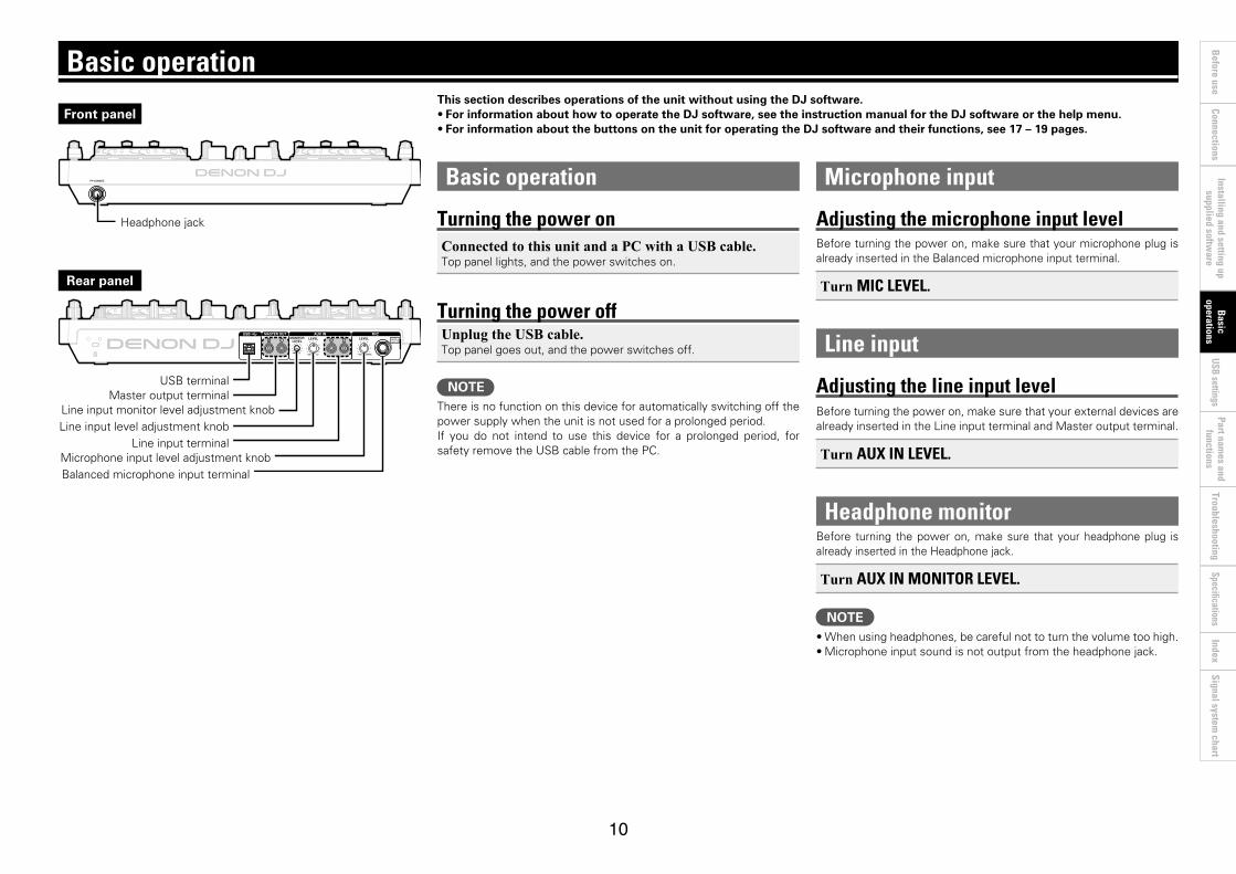
Basic operation
Turning the power onConnected to this unit and a PC with a USB cable.Top panel lights, and the power switches on.
Turning the power offUnplug the USB cable.Top panel goes out, and the power switches off.
NOTEThere is no function on this device for automatically switching off the power supply when the unit is not used for a prolonged period.If you do not intend to use this device for a prolonged period, for safety remove the USB cable from the PC.
Basic operation
Microphone input
Adjusting the microphone input levelBefore turning the power on, make sure that your microphone plug is already inserted in the Balanced microphone input terminal.
Turn MIC LEVEL.
Line input
Adjusting the line input level Before turning the power on, make sure that your external devices are already inserted in the Line input terminal and Master output terminal.
Turn AUX IN LEVEL.
Headphone monitorBefore turning the power on, make sure that your headphone plug is already inserted in the Headphone jack.
Turn AUX IN MONITOR LEVEL.
NOTE•When using headphones, be careful not to turn the volume too high.•Microphone input sound is not output from the headphone jack.
This section describes operations of the unit without using the DJ software. •For information about how to operate the DJ software, see the instruction manual for the DJ software or the help menu.•For information about the buttons on the unit for operating the DJ software and their functions, see 17 – 19 pages.
Front panel
Rear panel
Headphone jack
USB terminal
Line input monitor level adjustment knobLine input level adjustment knob
Line input terminalMicrophone input level adjustment knobBalanced microphone input terminal
Master output terminal
11
Before use
Part names and
functions Connections
Installing and setting up supplied softw
areUSB settings
Troubleshooting Index
Specifications Signal system
chart B
asic operations
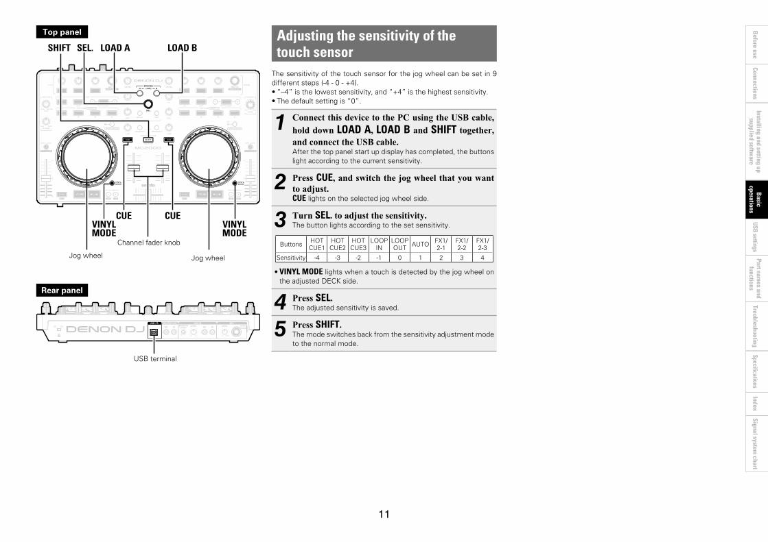
Adjusting the sensitivity of the touch sensor
The sensitivity of the touch sensor for the jog wheel can be set in 9 different steps (-4 - 0 - +4).•“–4” is the lowest sensitivity, and “+4” is the highest sensitivity.•The default setting is “0”.
1 Connect this device to the PC using the USB cable, hold down LOAD A, LOAD B and SHIFT together, and connect the USB cable. After the top panel start up display has completed, the buttons light according to the current sensitivity.
2 Press CUE, and switch the jog wheel that you want to adjust.CUE lights on the selected jog wheel side.
3 Turn SEL. to adjust the sensitivity.The button lights according to the set sensitivity.
Buttons HOT CUE1
HOT CUE2
HOT CUE3
LOOP IN
LOOP OUT AUTO FX1/
2-1FX1/ 2-2
FX1/ 2-3
Sensitivity -4 -3 -2 -1 0 1 2 3 4
•VINYL MODE lights when a touch is detected by the jog wheel on the adjusted DECK side.
4 Press SEL.The adjusted sensitivity is saved.
5 Press SHIFT.The mode switches back from the sensitivity adjustment mode to the normal mode.
LOAD A LOAD BSEL.SHIFT
CUEVINYLMODE
VINYLMODE
CUE
Top panel
Channel fader knob
Rear panel
Jog wheel Jog wheel
USB terminal

12
Before use
Part names and
functions Connections
Installing and setting up supplied softw
areTroubleshooting
IndexSpecifications
Signal system chart
Basic
operations USB settings
SHIFT lock functionVariousfunctionscanbeusedbyholdingdownSHIFT and pressing other buttons. By using the SHIFT Lock function, however, it is possible to use the same functions that are accessed by holding down SHIFT without needing to hold down SHIFT.
Locking SHIFTHold down SHIFT and press either one of the MONITOR CUE buttons on the left or right of SHIFT. The LOCK display lights indicating SHIFT is locked.
Cancelling SHIFT lockWhile SHIFT is locked, hold down SHIFT and press either one of the MONITOR CUE buttons on the left or right of SHIFT. The LOCK LED turns off and SHIFT lock is cancelled.
MONITORCUE
SHIFT
Top panel USB settings
USB AUDIO InputThis device is equipped with a sound card function that enables a maximum of 2 channels (stereo, 2 input) of USB AUDIO input.Further, the DJ software mixer output is output from the master output terminal or headphone terminal of this device.
•USB 1/2 channel input DJ software master•USB 3/4 channel input DJ software cue monitor
13
Before use
Part names and
functions Connections
Basic
operations Installing and setting up
supplied software
Troubleshooting Index
Specifications Signal system
chart USB settings
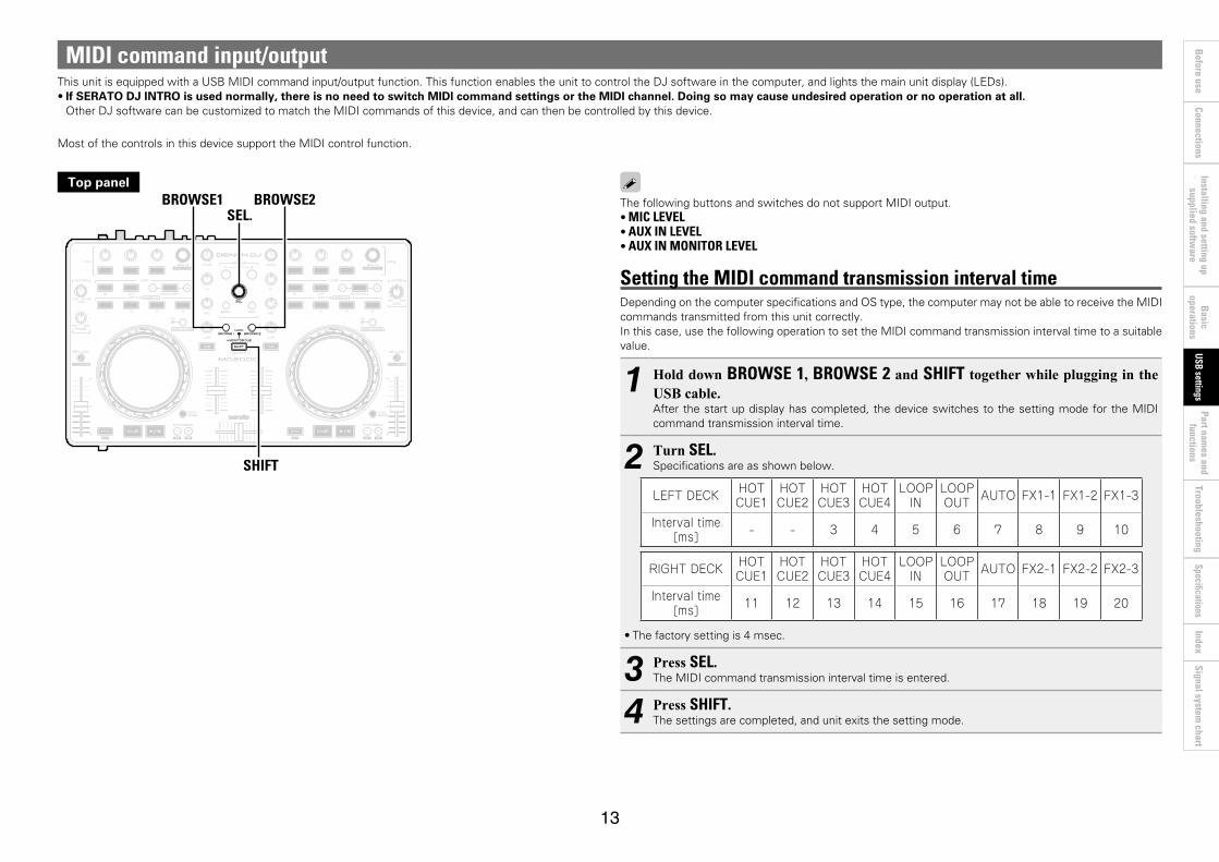
MIDI command input/outputThisunitisequippedwithaUSBMIDIcommandinput/outputfunction.ThisfunctionenablestheunittocontroltheDJsoftwareinthecomputer,andlightsthemainunitdisplay(LEDs).•If SERATO DJ INTRO is used normally, there is no need to switch MIDI command settings or the MIDI channel. Doing so may cause undesired operation or no operation at all.OtherDJsoftwarecanbecustomizedtomatchtheMIDIcommandsofthisdevice,andcanthenbecontrolledbythisdevice.
Most of the controls in this device support the MIDI control function.
SHIFT
BROWSE1SEL.
BROWSE2Top panel
The following buttons and switches do not support MIDI output.•MIC LEVEL•AUX IN LEVEL•AUX IN MONITOR LEVEL
Setting the MIDI command transmission interval timeDepending on the computer specifications and OS type, the computer may not be able to receive the MIDI commands transmitted from this unit correctly.In this case, use the following operation to set the MIDI command transmission interval time to a suitable value.
1 Hold down BROWSE 1, BROWSE 2 and SHIFT together while plugging in the USB cable. After the start up display has completed, the device switches to the setting mode for the MIDI command transmission interval time.
2 Turn SEL.Specifications are as shown below.
LEFT DECK HOT CUE1
HOT CUE2
HOT CUE3
HOT CUE4
LOOP IN
LOOP OUT AUTO FX1-1 FX1-2 FX1-3
Interval time [ms] - - 3 4 5 6 7 8 9 10
RIGHT DECK HOT CUE1
HOT CUE2
HOT CUE3
HOT CUE4
LOOP IN
LOOP OUT AUTO FX2-1 FX2-2 FX2-3
Interval time [ms] 11 12 13 14 15 16 17 18 19 20
•The factory setting is 4 msec.
3 Press SEL.The MIDI command transmission interval time is entered.
4 Press SHIFT.The settings are completed, and unit exits the setting mode.
14
Before use
Part names and
functions Connections
Basic
operations Installing and setting up
supplied software
Troubleshooting Index
Specifications Signal system
chart USB settings
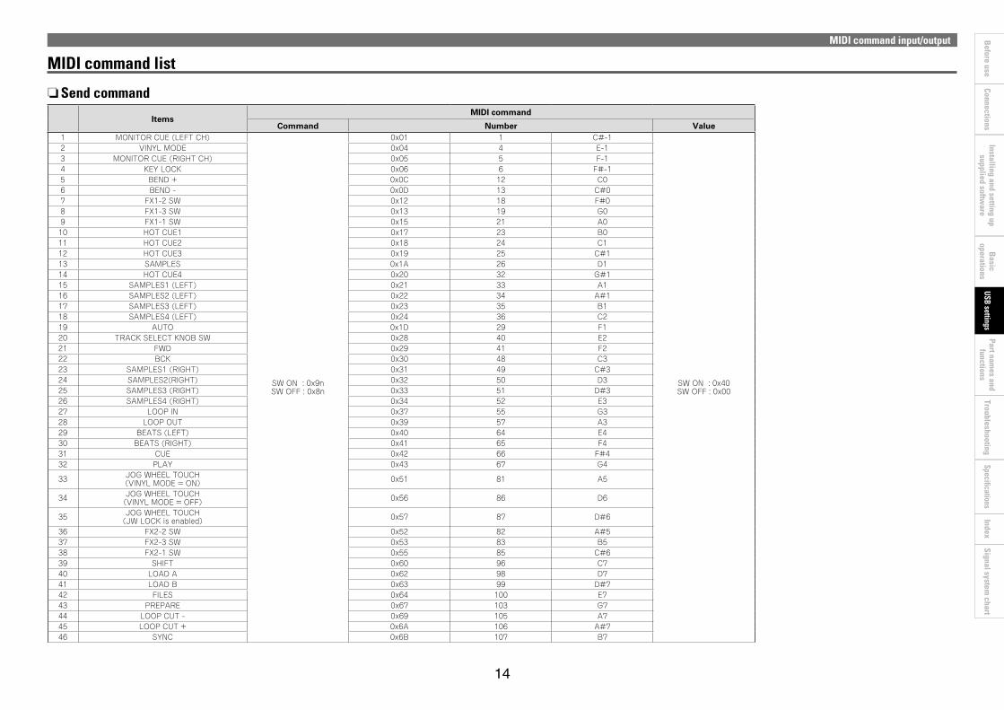
MIDI command input/output
nSend command
ItemsMIDI command
Command Number Value1 MONITOR CUE (LEFT CH)
SW ON : 0x9n SW OFF : 0x8n
0x01 1 C#-1
SW ON : 0x40 SW OFF : 0x00
2 VINYL MODE 0x04 4 E-13 MONITOR CUE (RIGHT CH) 0x05 5 F-14 KEY LOCK 0x06 6 F#-15 BEND + 0x0C 12 C06 BEND - 0x0D 13 C#07 FX1-2 SW 0x12 18 F#08 FX1-3 SW 0x13 19 G09 FX1-1 SW 0x15 21 A010 HOT CUE1 0x17 23 B011 HOT CUE2 0x18 24 C112 HOT CUE3 0x19 25 C#113 SAMPLES 0x1A 26 D114 HOT CUE4 0x20 32 G#115 SAMPLES1 (LEFT) 0x21 33 A116 SAMPLES2 (LEFT) 0x22 34 A#117 SAMPLES3 (LEFT) 0x23 35 B118 SAMPLES4 (LEFT) 0x24 36 C219 AUTO 0x1D 29 F120 TRACK SELECT KNOB SW 0x28 40 E221 FWD 0x29 41 F222 BCK 0x30 48 C323 SAMPLES1 (RIGHT) 0x31 49 C#324 SAMPLES2(RIGHT) 0x32 50 D325 SAMPLES3 (RIGHT) 0x33 51 D#326 SAMPLES4 (RIGHT) 0x34 52 E327 LOOP IN 0x37 55 G328 LOOP OUT 0x39 57 A329 BEATS (LEFT) 0x40 64 E430 BEATS (RIGHT) 0x41 65 F431 CUE 0x42 66 F#432 PLAY 0x43 67 G4
33 JOG WHEEL TOUCH (VINYL MODE = ON) 0x51 81 A5
34 JOG WHEEL TOUCH (VINYL MODE = OFF) 0x56 86 D6
35 JOG WHEEL TOUCH (JW LOCK is enabled) 0x57 87 D#6
36 FX2-2 SW 0x52 82 A#537 FX2-3 SW 0x53 83 B538 FX2-1 SW 0x55 85 C#639 SHIFT 0x60 96 C740 LOAD A 0x62 98 D741 LOAD B 0x63 99 D#742 FILES 0x64 100 E743 PREPARE 0x67 103 G744 LOOP CUT - 0x69 105 A745 LOOP CUT + 0x6A 106 A#746 SYNC 0x6B 107 B7
MIDI command list

15
Before use
Part names and
functions Connections
Basic
operations Installing and setting up
supplied software
Troubleshooting Index
Specifications Signal system
chart USB settings
ItemsMIDI command
Command Number Value
47 JOG WHEEL FWD/REV (VINYL MODE = ON) 0xBn 0x51 81
Reverse 0x3F~0x01 Foward 0x41~0x7F
slow->fast ※ relative data
48 JOG WHEEL FWD/REV (VINYL MODE = OFF) 0xBn 0x52 82
Reverse 0x3F~0x01 Foward 0x41~0x7F
slow->fast ※ relative data
49 JOG WHEEL FWD/REV (JW LOCK is Enabled)
0xBn
0x53 83
Reverse 0x3F~0x01 Foward 0x41~0x7F
slow->fast ※ relative data
50 TRACK SELECT KNOB Increment/Decrement 0x54 84 Increment 0x01
Decrement 0x7F
51 FX1-1 KNOB Increment/Decrement 0x55 85
0x00 to 0x7F
52 FX1-2 KNOB Increment/Decrement 0x56 86
53 FX1-3 KNOB Increment/Decrement 0x57 87
54 BEATS KNOB (FX1) Increment/Decrement 0x58 88
55 FX2-1 KNOB Increment/Decrement 0x59 89
56 FX2-2 KNOB Increment/Decrement 0x5A 90
57 FX2-3 KNOB Increment/Decrement 0x5B 91
58 BEATS KNOB (FX2) Increment/Decrement 0x5C 92
59 INPUT LEVEL (LEFT CH) 0x01 160 EQ HIGH VR (LEFT CH) 0x02 261 EQ MID VR (LEFT CH) 0x03 362 EQ LOW VR (LEFT CH) 0x04 463 CHANNEL FADER (L) 0x05 564 INPUT LEVEL (LEFT2 CH) 0x07 765 EQ HIGH VR (LEFT2 CH) 0x08 866 EQ MID VR (LEFT2 CH) 0x09 967 EQ LOW VR (LEFT2 CH) 0x0A 1068 CHANNEL FADER (L2) 0x0B 1169 INPUT LEVEL (RIGHT CH) 0x0C 1270 EQ HIGH VR (RIGHT CH) 0x0D 1371 EQ MID VR (RIGHT CH) 0x0E 1472 EQ LOW VR (RIGHT CH) 0x0F 1573 CHANNEL FADER (R) 0x10 1674 INPUT LEVEL (RIGHT2 CH) 0x11 1775 EQ HIGH VR (RIGHT2 CH) 0x12 1876 EQ MID VR (RIGHT2 CH) 0x13 1977 EQ LOW VR (RIGHT2 CH) 0x14 2078 CHANNEL FADER (R2) 0x15 2179 CROSS FADER 0x16 2280 MASTER VR 0x19 4181 MONITOR PAN 0x43 6782 PHONES 0x44 6883 Pitch Slider 0xEn 0xll(LSB) 0xll(LSB) 0xmm(MSB)
※ n=MIDI CH = 0~1
MIDI command input/output

16
Before use
Part names and
functions Connections
Basic
operations Installing and setting up
supplied software
Troubleshooting Index
Specifications Signal system
chart USB settings
MIDI command input/output
nReception commandsItems
(Lit display (LED))MIDI command
Command Number1 SHIFT LOCK
0xBn
ON TRG : 0x4A OFF TRG : 0x4B
Blink ON TRG : 0x4C
0x02 22 VINYL MODE 0x06 63 KEY LOCK 0x08 84 SYNC 0x09 95 CUE1 0x11 176 CUE2 0x13 197 CUE3 0x15 218 CUE4 0x17 239 SAMP.1 (LEFT) 0x19 2510 SAMP.2 (LEFT) 0x1B 2711 SAMP.3 (LEFT) 0x1D 2912 SAMP.4 (LEFT) 0x20 3213 SAMPLES (LEFT) 0x23 3514 SAMP.1 (RIGHT) 0x41 6515 SAMP.2 (RIGHT) 0x43 6716 SAMP.3 (RIGHT) 0x45 6917 SAMP.4 (RIGHT) 0x47 7118 SAMPLES (RIGHT) 0x49 7319 CUE 0x26 3820 PLAY 0x27 5521 LOOP IN 0x24 3622 LOOP OUT 0x40 6423 AUTO LOOP 0x2B 4324 FX1-1 0x5C 9225 FX1-2 0x5D 9326 FX1-3 0x5E 9427 FX2-1 0x60 9628 FX2-2 0x61 9729 FX2-3 0x62 9830 ALL SLIDER/VOLUME/FADER REQUEST 0x4A 0x39 5731 MONITOR CUE (LEFT CH) ON TRG: 0x50
OFF TRG: 0x510x45 69
32 MONITOR CUE (RIGHTCH) 0x51 81
※ n=MIDI CH = 0~1
Range of MIDI CH1
Range of MIDI CH2
17
Before use
Connections B
asic operations
Installing and setting up supplied softw
areUSB settings
Troubleshooting Index
Specifications Signal system
chart Part nam
es and functions
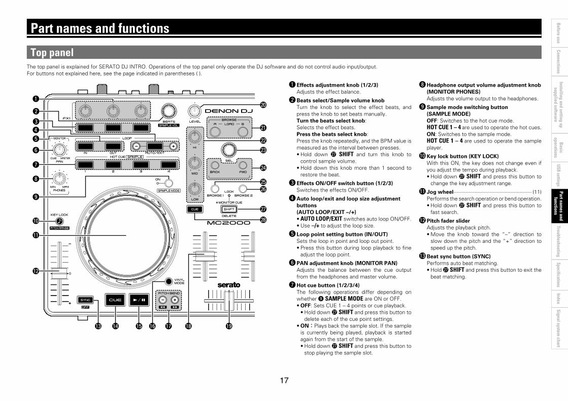
ThetoppanelisexplainedforSERATODJINTRO.OperationsofthetoppanelonlyoperatetheDJsoftwareanddonotcontrolaudioinput/output.For buttons not explained here, see the page indicated in parentheses ( ).
Part names and functions
Top panel
q Effects adjustment knob (1/2/3)Adjusts the effect balance.
w Beats select/Sample volume knobTurn the knob to select the effect beats, and press the knob to set beats manually. Turn the beats select knob:Selects the effect beats.Press the beats select knob:Press the knob repeatedly, and the BPM value is measured as the interval between presses. •Hold down W7 SHIFT and turn this knob to
control sample volume.•Hold down this knob more than 1 second to
restore the beat.
e Effects ON/OFF switch button (1/2/3)SwitchestheeffectsON/OFF.
r Auto loop/exit and loop size adjustment buttons (AUTO LOOP/EXIT –/+)•AUTO LOOP/EXITswitchesautoloopON/OFF.•Use –/+toadjusttheloopsize.
t Loop point setting button (IN/OUT)Sets the loop in point and loop out point.•Press this button during loop playback to fine
adjust the loop point.
y PAN adjustment knob (MONITOR PAN)Adjusts the balance between the cue output from the headphones and master volume.
u Hot cue button (1/2/3/4)The following operations differ depending on whether o SAMPLE MODE are ON or OFF.•OFF: Sets CUE 1 – 4 points or cue playback.•Hold down W7 SHIFT and press this button to
delete each of the cue point settings.•ON:Plays back the sample slot. If the sample
is currently being played, playback is started again from the start of the sample.•Hold down W7 SHIFT and press this button to
stop playing the sample slot.
Q3 Q4 Q6 Q9Q8Q5
W8
W7
W6
W4
W1
W3
W2
W5
W0
Q7
q
w
e
y
i
o
Q2
Q0
Q1
u
t
r
i Headphone output volume adjustment knob (MONITOR PHONES)Adjusts the volume output to the headphones.
o Sample mode switching button (SAMPLE MODE)OFF: Switches to the hot cue mode.HOT CUE 1 – 4 are used to operate the hot cues.ON: Switches to the sample mode.HOT CUE 1 – 4 are used to operate the sample player.
Q0 Key lock button (KEY LOCK)With this ON, the key does not change even if you adjust the tempo during playback.•Hold down W7 SHIFT and press this button to
change the key adjustment range.
Q1 Jog wheel ···················································· (11)Performs the search operation or bend operation. •Hold down W7 SHIFT and press this button to
fast search.
Q2 Pitch fader sliderAdjusts the playback pitch.•Move the knob toward the “–” direction to
slow down the pitch and the “+” direction to speed up the pitch.
Q3 Beat sync button (SYNC)Performs auto beat matching.•Hold W7 SHIFT and press this button to exit the
beat matching.
18
Before use
Connections B
asic operations
Installing and setting up supplied softw
areUSB settings
Troubleshooting Index
Specifications Signal system
chart Part nam
es and functions
Top panel
Q3 Q4 Q6 Q9Q8Q5
W8
W7
W6
W4
W1
W3
W2
W5
W0
Q7
q
w
e
y
i
o
Q2
Q0
Q1
u
t
r
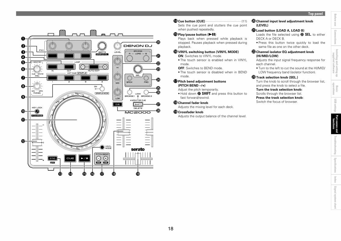
Q4 Cue button (CUE) ······································· (11)Sets the cue point and stutters the cue point when pushed repeatedly.
Q5 Play/pause button (13)Plays back when pressed while playback is stopped. Pauses playback when pressed during playback.
Q6 VINYL switching button (VINYL MODE)ON:SwitchestoVINYLmode.•The touch sensor is enabledwhen in VINYL
mode.OFF: Switches to BEND mode.•The touch sensor is disabled when in BEND
mode.
Q7 Pitch bend adjustment buttons (PITCH BEND –/+)Adjust the pitch temporarily.•Hold down W7 SHIFT and press this button to fastforward/rewind.
Q8 Channel fader knobAdjusts the mixing level for each deck.
Q9 Crossfader knobAdjusts the output balance of the channel level.
W0 Channel input level adjustment knob (LEVEL)
W1 Load button (LOAD A, LOAD B)Loads the file selected using W3 SEL. to either DECK A or DECK B. •Press this button twice quickly to load the
same file as one on the other deck.
W2 Channel isolator EQ adjustment knob (HI/MID/LOW)Adjusts the input signal frequency response for each channel.•TurntothelefttocutthesoundattheHI/MID/
LOW frequency band (isolator function).
W3 Track selection knob (SEL.)Turn the knob to scroll through the browser list, and press the knob to select a file.Turn the track selection knob:Scrolls through the browser list.Press the track selection knob:Switch the focus of browser.

19
Before use
Connections B
asic operations
Installing and setting up supplied softw
areUSB settings
Troubleshooting Index
Specifications Signal system
chart Part nam
es and functions
Top panel
Q3 Q4 Q6 Q9Q8Q5
W8
W7
W6
W4
W1
W3
W2
W5
W0
Q7
q
w
e
y
i
o
Q2
Q0
Q1
u
t
r
W4 Window switch button (BACK/FWD)Move the cursor.
W5 BROWSE 1 button (BROWSE 1)Not used in SERATO DJ INTRO operation.
W6 BROWSE 2 button (BROWSE 2)Not used in SERATO DJ INTRO operation.
W7 SHIFT button (SHIFT)
W8 MONITOR CUE button (MONITOR CUE)The source of the channel selected using MONITOR CUE is mixed with the monitor, and output to the headphones.•Hold down W7 SHIFT and press this button to
lock the SHIFT function. The LOCK display lights (SHIFT lock function).
W9 Master output volume adjustment knob (MASTER LEVEL)Adjusts the volume output from the master output terminal.
W9

20
Before use
Connections B
asic operations
Installing and setting up supplied softw
areUSB settings
Troubleshooting Index
Specifications Signal system
chart Part nam
es and functions
Front panelFor buttons not explained here, see the page indicated in parentheses ( ).
q
Rear panelFor buttons not explained here, see the page indicated in parentheses ( ).
ew rq iuyt
q Headphone jack (PHONES) ························ (10) q Theft protection lock holeConnect to an anti-theft wire.
w USB terminal (USB)
e Master output terminal (MASTER OUT) ··········································· (10)
r Line input moniter level adjustment knob (AUX IN MONITOR LEVEL) ························ (10)Adjusts the volume of the input line to be output from the headphone jack.
t Line input level adjustment knob (AUX IN LEVEL) ·········································· (10)Adjusts the volume of the input line to be output from the master output terminal.
y AUX IN input terminal (AUX IN) ······················································ (10)
u Microphone input level adjustment knob (MIC LEVEL) ················································ (10)
i Balanced microphone input terminal (MIC) ···························································· (10)
21
Before use
Part names and
functions Connections
Basic
operations Installing and setting up
supplied software
USB settings Index
Signal system chart
Troubleshooting Specifications
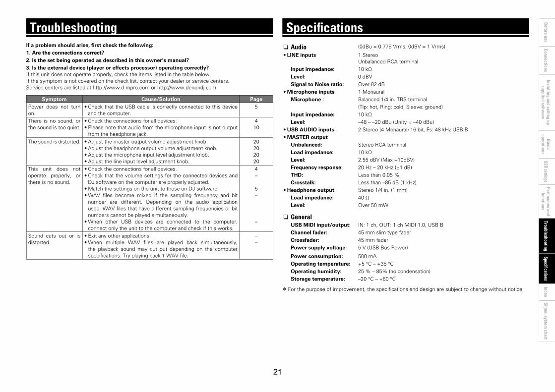
If a problem should arise, first check the following:1. Are the connections correct?2. Is the set being operated as described in this owner’s manual?3. Is the external device (player or effects processor) operating correctly? If this unit does not operate properly, check the items listed in the table below.If the symptom is not covered on the check list, contact your dealer or service centers.Servicecentersarelistedathttp://www.d-mpro.comorhttp://www.denondj.com.
Symptom Cause/Solution PagePower does not turn on.
•Check that the USB cable is correctly connected to this device and the computer.
5
There is no sound, or the sound is too quiet.
•Check the connections for all devices.•Please note that audio from the microphone input is not output
from the headphone jack.
410
The sound is distorted. •Adjust the master output volume adjustment knob. •Adjust the headphone output volume adjustment knob. •Adjust the microphone input level adjustment knob. •Adjust the line input level adjustment knob.
20202020
This unit does not operate properly, or there is no sound.
•Check the connections for all devices.•Check that the volume settings for the connected devices and
DJ software on the computer are properly adjusted.•Match the settings on the unit to those on DJ software.•WAV files become mixed if the sampling frequency and bit
number are different. Depending on the audio application used,WAVfilesthathavedifferentsamplingfrequenciesorbitnumbers cannot be played simultaneously.
•When other USB devices are connected to the computer, connect only the unit to the computer and check if this works.
4–
5–
–
Sound cuts out or is distorted.
•Exit any other applications.•When multiple WAV files are played back simultaneously,
the playback sound may cut out depending on the computer specifications.Tryplayingback1WAVfile.
––
Troubleshooting n Audio (0dBu=0.775Vrms,0dBV=1Vrms)
•LINE inputs 1 Stereo Unbalanced RCA terminal
Input impedance: 10 kΩLevel: 0dBVSignal to Noise ratio: Over 82 dB
•Microphone inputs 1 MonauralMicrophone : Balanced1/4in.TRSterminal
(Tip: hot, Ring: cold, Sleeve: ground)Input impedance: 10 kΩLevel: –48 – –20 dBu (Unity = –40 dBu)
•USB AUDIO inputs 2Stereo(4Monaural)16bit,Fs:48kHzUSBB•MASTER output
Unbalanced: Stereo RCA terminalLoad impedance: 10 kΩLevel: 2.55dBV(Max+10dBV)Frequency response: 20Hz–20kHz(±1dB)THD: Less than 0.05 %Crosstalk: Lessthan–85dB(1kHz)
•Headphone output Stereo1/4in.(1mm)Load impedance: 40 ΩLevel: Over 50 mW
n GeneralUSB MIDI input/output: IN: 1 ch, OUT: 1 ch MIDI 1.0, USB BChannel fader: 45 mm slim type faderCrossfader: 45 mm faderPower supply voltage: 5V(USBBusPower)
Power consumption: 500 mAOperating temperature: +5 °C – +35 °COperating humidity: 25 % – 85% (no condensation)Storage temperature: –20 °C – +60 °C
z For the purpose of improvement, the specifications and design are subject to change without notice.
Specifications

22
Before use
Part names and
functions Connections
Basic
operations Installing and setting up
supplied software
USB settings Troubleshooting
Specifications Signal system
chart Index
v AASIO driver ··························································· 6
v CCable ···································································· 4
Coaxial cable for microphone ····························· 4RCA pin plug cable············································· 4USB cable ·························································· 4
Condensation ······················································· 3Connection ··························································· 4
Audio Player ······················································· 4Computer ··························································· 5Microphone························································ 4Unbalanced main input ······································ 4
v FFront panel ························································· 20
v HHeadphone monitor ··········································· 10
v LLine input ··························································· 10
v MMicrophone ························································ 10MIDI command ············································· 13,14
v PPoweron/off ······················································ 10
v RRear panel ·························································· 20
v SSERATO DJ INTRO ·············································· 9SHIFT lock function ············································ 12
v TTop panel ·················································· 17,18,19Touch sensor ······················································ 11
v UUSB AUDIO ························································ 12USB settings ······················································ 12
Index

23
Before use
Part names and
functions Connections
Basic
operations Installing and setting up
supplied software
USB settings Troubleshooting
IndexSpecifications
Signal system chart
Signal system chart
DA
DA
24
Before use
Part names and
functions Connections
Basic
operations Installing and setting up
supplied software
USB settings Troubleshooting
IndexSpecifications
Signal system chart
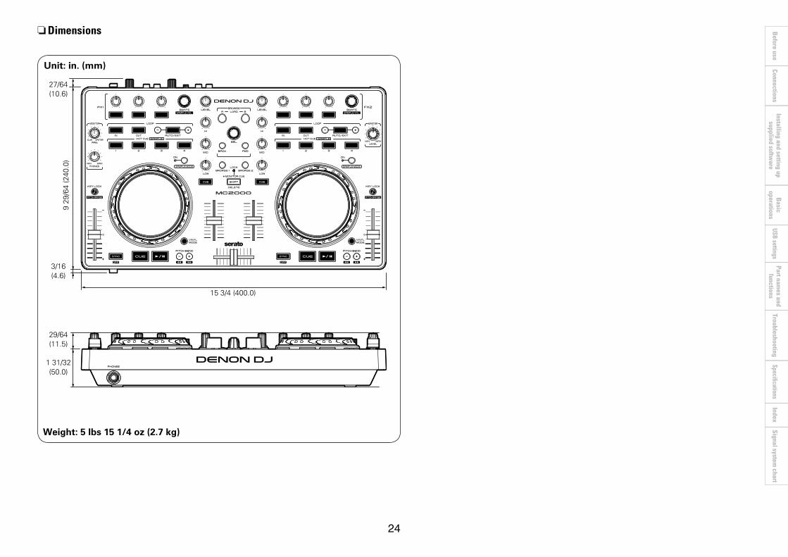
nDimensions
Unit: in. (mm)
153/4(400.0)
27/64(10.6)
29/64(11.5)
131/32(50.0)
929
/64(240
.0)
3/16(4.6)
Weight: 5 lbs 15 1/4 oz (2.7 kg)

V00 3520 10165 00AP