Embed Size (px)
Citation preview
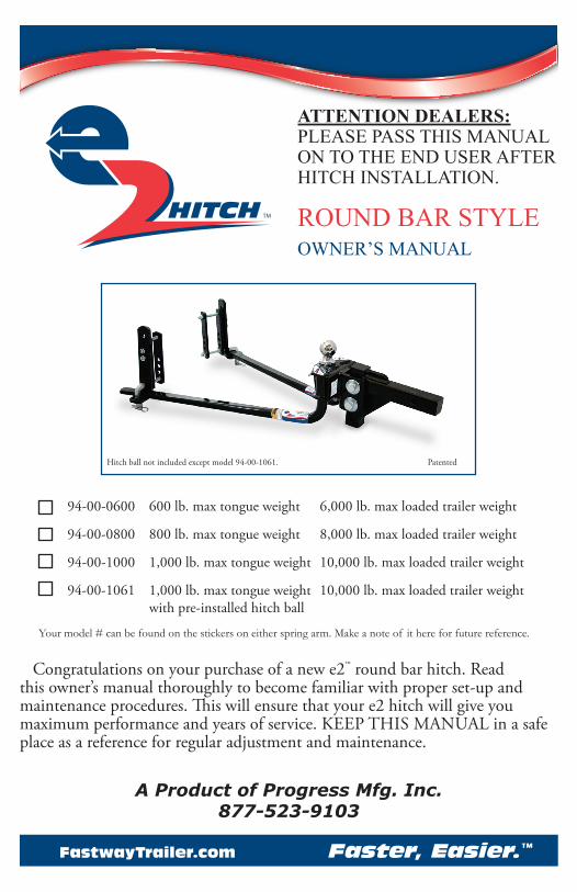
94-00-0600 600 lb. max tongue weight 6,000 lb. max loaded trailer weight
94-00-0800 800 lb. max tongue weight 8,000 lb. max loaded trailer weight
94-00-1000 1,000 lb. max tongue weight 10,000 lb. max loaded trailer weight
94-00-1061 1,000 lb. max tongue weight 10,000 lb. max loaded trailer weight with pre-installed hitch ball
Your model # can be found on the stickers on either spring arm. Make a note of it here for future reference.
OWNER’S MANUAL
A Product of Progress Mfg. Inc.877-523-9103
Congratulations on your purchase of a new e2™ round bar hitch. Read this owner’s manual thoroughly to become familiar with proper set-up and maintenance procedures. This will ensure that your e2 hitch will give you maximum performance and years of service. KEEP THIS MANUAL in a safe place as a reference for regular adjustment and maintenance.
ATTENTION DEALERS: PLEASE PASS THIS MANUAL ON TO THE END USER AFTER HITCH INSTALLATION.
ROUND BAR STYLE
FastwayTrailer.com Faster, Easier.™
Hitch ball not included except model 94-00-1061. Patented

2 FastwayTrailer.com
2324
22
21
2019
1817
1615
14
1312
11
10
8 9
76
54
3
2 1
Item
#Pa
rt N
umbe
rPa
rt D
escr
ipti
onQ
ty.
192
-04-
9208
L-Pi
n C
lip2
293
-04-
9285
1/2”
Nyl
ock
Nut
43
92-0
3-92
05L-
Pin
24
93-0
2-51
50L-
Brac
ket
25
93-0
2-92
701/
2” x
4”
Bolt
- Gra
de 5
46
93-0
2-53
50St
udde
d O
utsid
e Li
nk P
late
27
93-0
2-52
00In
side
Link
Pla
te2
892
-04-
9228
1/2”
Nut
49
92-0
4-92
901/
2” L
ock
Was
her
410
92-0
0-60
00Sn
ap-u
p Le
ver
111
92-0
3-97
005/
8” A
ngle
Set
Bol
t1
12*
94-0
2-06
996,
000
lb. S
prin
g Ar
m (s
ingl
e)2*
94-0
2-08
998,
000
lb. S
prin
g Ar
m (s
ingl
e)94
-02-
1099
10,0
00 lb
. Spr
ing
Arm
(sng
l.)
Item
#Pa
rt N
umbe
rPa
rt D
escr
ipti
onQ
ty.
13BD
094-
WS
Arm
Stic
ker
214
92-0
4-96
403/
4” N
yloc
k N
ut2
1592
-04-
9645
3/4”
Con
ical
Too
thed
Was
her
416
BD09
4-AH
War
ning
Stic
ker
117
92-0
4-96
25H
itch
Pin
118
92-0
2-41
007”
Rise
x 1
” D
rop
Adj.
Shan
k1
1992
-04-
9630
Hitc
h Pi
n C
lip1
2092
-04-
9650
Spac
er R
ivet
121
92-0
4-96
55Sp
acer
Was
hers
722
92-0
4-96
353/
4-10
x 5
” G
rade
5 B
olt
223
**94
-02-
1055
e2 R
ound
Bar
Hitc
h H
ead
124
‡--
Hitc
h Ba
llN
SBD
094
e2 R
ound
Bar
Instr
uctio
n M
anua
l1
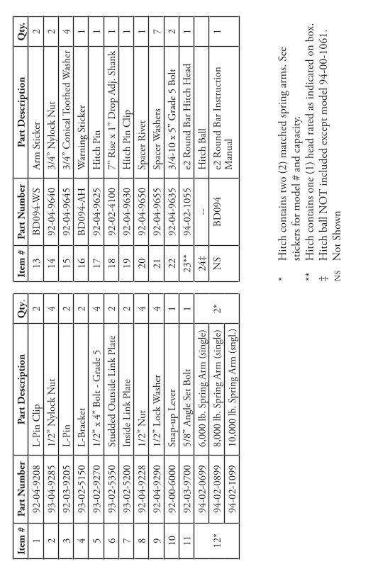
* H
itch
cont
ains
two
(2) m
atch
ed sp
ring
arm
s. Se
e sti
cker
s for
mod
el #
and
cap
acity
.**
H
itch
cont
ains
one
(1) h
ead
rate
d as
indi
cate
d on
box
.‡
Hitc
h ba
ll N
OT
incl
uded
exc
ept m
odel
94-
00-1
061.
NS
Not
Sho
wn

4 FastwayTrailer.com
Table of Contents Page
Parts Breakdown. . . . . . . . . . . . . . . . . . . . . . . . . . . . 2-3Important Safety Information . . . . . . . . . . . . . . . . . . . . . . 5Important Hitch Information . . . . . . . . . . . . . . . . . . . . . . 7Step 1: Getting Things Ready . . . . . . . . . . . . . . . . . . . . . . 8Step 2: Install the Hitch Ball . . . . . . . . . . . . . . . . . . . . . . 9Step 3: Attach Hitch Head to Shank . . . . . . . . . . . . . . . . . 10Step 4: Sway Bracket Assembly Set Up . . . . . . . . . . . . . . . . 12Step 5: Install Spring Arms . . . . . . . . . . . . . . . . . . . . . . 14Step 6: Weight Distribution Setup. . . . . . . . . . . . . . . . . . . 14Step 7: Weight Distribution Adjustments . . . . . . . . . . . . . . . 17Step 8: Trailer Angle Adjustments . . . . . . . . . . . . . . . . . . . 20Step 9: Final Tightening . . . . . . . . . . . . . . . . . . . . . . . . 20Step 10: Regular Maintenance. . . . . . . . . . . . . . . . . . . . . 21 Customer Support. . . . . . . . . . . . . . . . . . . . . . . . . . . 22Appendix A: Troubleshooting Guide . . . . . . . . . . . . . . . . . 23Appendix B: Weight Distribution Adjustments . . . . . . . . . . . . 24Warranty . . . . . . . . . . . . . . . . . . . . . . . . . . . . . . . 25Frequently Asked Questions (FAQ) . . . . . . . . . . . . . . . . . . 26
TOOLS NEEDED FOR INSTALLATION
The following tools will help you to install your hitch. 1-1/8” Socket or Box End Wrench (Shank Bolts)1-1/16” Socket or Box End Wrench (Shank Nut)Torque Wrench capable of 250 ft-lbs. of torque. (Shank bolts)3/4” Socket or Box End Wrench (Link Plates and L-brackets)15/16” Socket or Box End Wrench (Angle Set Bolt)Measuring TapePencil
Recommended tools for installing the Hitch Ball:1-7/8” SocketTorque Wrench capable of reaching torque specifications recommended
by hitch ball manufacturer.

5A Product of Progress Mfg. Inc.
Important Safety Information Failure to follow all safety warnings may result in severe injury or death.
WARNING
WARNINGRead, understand, and follow all safety warnings, setup, use, and main‑tenance instructions of your trailer, tow vehicle, and hitching equipment before installing your hitch or towing your trailer.
Never cut, weld, grind, bend, or modify hitch components in any way.
It is the driver’s responsibility to adjust equipment and driving habits to
Warning Stickers Arm Sticker
(not actual size)
Head StickerFaster, Easier.
Meets or Exceeds V5 and SAE Requirements. The e2™ hitch is a product of Progress Mfg. Inc.
600 Lbs. maximum tongue weight6,000 Lbs. maximum trailer weight
For a copy of the instructions visitwww.FastwayTrailer.com
The e2™ hitch is a product of Progress Mfg. Inc.Meets V5 and SAE standards.
E2RB_0710
Impr
oper
set
up c
an c
ause
sev
ere
inju
ry o
r dea
th.
•
Read
and
follo
w o
wne
r’s m
anua
l at a
ll tim
es.
•
Chec
k fo
r pro
per s
etup
bef
ore
tow
ing.
ROUND BAR — 94-00-0600
Faster, Easier.
Meets or Exceeds V5 and SAE Requirements.The e2™ hitch is a product of Progress Mfg. Inc.
ATTENTION Changes in tow vehicle & trailer loading can change weight distribution requirements and vehicle handling. For best performance check your hitch setup often. Verify that proper weight distribution is achieved. Refer to owner’s manual.
E2RB_0911

6 FastwayTrailer.com
match towing conditions. The driver is responsible for their own safety and the safety of passengers.
Never exceed the specified weight ratings for the trailer, tow vehicle, hitch, hitch ball, or any other towing equipment.
No hitch setup guarantees that trailer sway will be altogether avoided.
Always load trailer correctly. Follow trailer and tow vehicle manufacturer’s recommendations for placement and quantity of cargo.
Always tow with a minimum tongue weight of 10% of the gross trailer weight.
Always use a hitch ball with a rating that equals or exceeds the trailer Gross Vehicle Weight Rating (GVWR). Always use a hitch ball size that correctly matches your trailer coupler size and make sure it is coupled securely be‑fore towing.
“Good” weight distribution setup does not ensure safe towing. The opera‑tor is responsible for making necessary adjustments to the hitch to opti‑mize weight distribution and sway control. Each trip is different, and the weight distribution setup and towing performance should be evaluated by the operator and adjusted when necessary.
Never tow with your hitch adjusted incorrectly.
Check all hardware before each trip. Do not tow your trailer until all bolts and nuts have been checked for wear and fatigue, are properly tightened, and all pins and clips are securely in place.
Do not tow your trailer on rough roads. Do not tow your trailer through profound ditches, dips, or swales. Excessive strain on the spring arms and hitch head may cause hitch fatigue or failure.
If your dealer installed your hitch, make sure to verify that it is still adjust‑ed correctly after loading your trailer and tow vehicle for your trip.
Replace all worn, faded, or unreadable warning stickers on the hitch im‑mediately.
Do not transfer hitch to a different tow vehicle or trailer without re‑adjust‑ing the hitch.
7A Product of Progress Mfg. Inc.
CAUTION
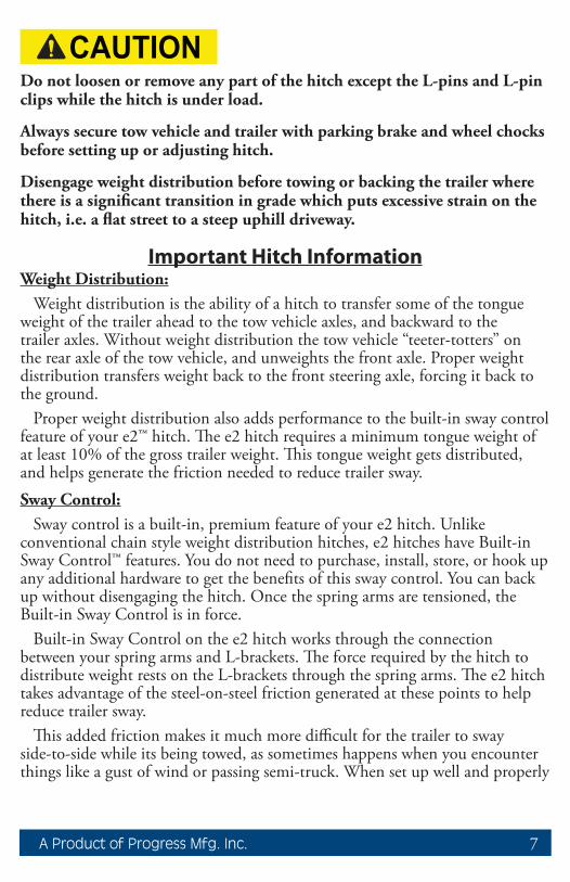
CAUTIONDo not loosen or remove any part of the hitch except the L‑pins and L‑pin clips while the hitch is under load.
Always secure tow vehicle and trailer with parking brake and wheel chocks before setting up or adjusting hitch.
Disengage weight distribution before towing or backing the trailer where there is a significant transition in grade which puts excessive strain on the hitch, i.e. a flat street to a steep uphill driveway.
Important Hitch InformationWeight Distribution:
Weight distribution is the ability of a hitch to transfer some of the tongue weight of the trailer ahead to the tow vehicle axles, and backward to the trailer axles. Without weight distribution the tow vehicle “teeter-totters” on the rear axle of the tow vehicle, and unweights the front axle. Proper weight distribution transfers weight back to the front steering axle, forcing it back to the ground.
Proper weight distribution also adds performance to the built-in sway control feature of your e2™ hitch. The e2 hitch requires a minimum tongue weight of at least 10% of the gross trailer weight. This tongue weight gets distributed, and helps generate the friction needed to reduce trailer sway.Sway Control:
Sway control is a built-in, premium feature of your e2 hitch. Unlike conventional chain style weight distribution hitches, e2 hitches have Built-in Sway Control™ features. You do not need to purchase, install, store, or hook up any additional hardware to get the benefits of this sway control. You can back up without disengaging the hitch. Once the spring arms are tensioned, the Built-in Sway Control is in force.
Built-in Sway Control on the e2 hitch works through the connection between your spring arms and L-brackets. The force required by the hitch to distribute weight rests on the L-brackets through the spring arms. The e2 hitch takes advantage of the steel-on-steel friction generated at these points to help reduce trailer sway.
This added friction makes it much more difficult for the trailer to sway side-to-side while its being towed, as sometimes happens when you encounter things like a gust of wind or passing semi-truck. When set up well and properly
8 FastwayTrailer.com
adjusted for your load, the e2 hitch can noticeably reduce sway through good weight distribution and the friction of Built-in Sway Control.Important Setup Information:
These instructions are a guideline to aid in setting up your hitch. Every trailer and tow vehicle combination requires a different setup and adjustment because of factors like trailer weight and length, trailer loading, hitch weight, and tow vehicle suspension and wheelbase. It is not likely that a good setup for one vehicle combination will work well for another. If you change the tow vehicle and/or trailer, you should change the hitch setup too.
You must use your best judgment to determine if changes to the setup are required to ensure a safe and comfortable towing situation. There is no all-inclusive formula for setting up or adjusting a hitch that will accommodate each combination of trailer and tow vehicle possible.
The setup may need to be changed slightly at times to accommodate changes in your towing configuration, perhaps even during the same trip. For example, a trailer that starts with full clean water and propane tanks, may tow differently when that water becomes black and grey water, and the propane tanks are empty. Or, a trailer loaded with gear for a long cross country trip may tow differently than the same trailer loaded for a weekend getaway. The driver must be conscious of these changes, and adjust the hitch accordingly.
A setup achieving adequate weight distribution usually brings the trailer back to a position parallel to the ground after coupling it to the tow vehicle and engaging weight distribution. It also brings the FRONT of the tow vehicle back down to just slightly higher than the uncoupled height. The REAR of the tow vehicle sits slightly lower than its uncoupled height, but higher than its height when coupled without weight distribution engaged.
There is no such thing as a “perfect” setup. The hitch should be set up to get the best results possible, and then adjusted as necessary for the best performance possible. You, as the operator, are responsible for your safety, and the safety of your passengers. Always follow all of the safety precautions described in this owner’s manual.
Remember, no setup guarantees that sway and other towing hazards will be altogether avoided. However, when set up and adjusted properly, we are confident that you will experience a much safer and more comfortable towing experience than you would if towing without a Fastway e2 hitch.
Set Up Your Hitch
Step 1 - Getting Things Ready:
Before installing the hitch, the tow vehicle and trailer should be loaded just

9A Product of Progress Mfg. Inc.
as they will be while traveling. This includes full propane tanks, fresh water tanks, and any other cargo (passengers & gear) the tow vehicle or trailer will carry, including ATVs for toy haulers. Tow vehicle “auto-level” systems should also be disabled or turned off. If your tow vehicle is equipped with air bags, we recommend that you inflate them to the pressure you are expecting to tow with before setting up the hitch. Inflating them after hitch set up changes the relationship between tow vehicle and trailer, and can reduce the amount of weight distribution and sway control you get from your hitch.
Park the trailer and tow vehicle on level ground and in line with each other. Chock and uncouple the trailer using the Fastway ONEstep (or similar) wheel chocks. Pull tow vehicle ahead about 5 feet to allow working area and set the parking brake.
Measure the FRONT and BACK of the trailer frame, and adjust the trailer to be parallel to the ground. Both FRONT and BACK measurements should be the same.
WARNING
WARNINGNever exceed the specified weight ratings for the trailer, tow vehicle, hitch, hitch ball, or any other towing equipment.
Step 2 - Install the Hitch Ball:
Remove the hitch head from the packaging and install a properly-sized hitch ball (not included). Ball diameter must match trailer coupler size.
Select a ball with a 1-1/4” diameter threaded shank. If your hitch ball has a smaller diameter shank you must use an appropriate bushing. Make sure that the ball has a weight rating equal to or greater than your trailer’s gross vehicle weight rating (GVWR). Always use a lock washer against the nut, unless otherwise specified by ball manufacturer. Torque nut to ball manufacturer’s specifications.
Whichever brand of hitch ball is used, make sure that it meets coupler and shank diameter size requirements and meets or exceeds all weight ratings.
Hitch balls require a 1-7/8” socket and a torque wrench capable of approximately 450 ft-lbs. torque for installation. Your nearest Fastway e2 dealership will have the tools needed and will usually install the hitch ball for a reasonable fee.

10 FastwayTrailer.com
Step 3 - Attach Hitch Head to Shank:
With the trailer parallel to the ground, measure from the ground to the inside top of the trailer coupler. See Figure 1.
Trailer Coupler Height: _______
The hitch ball should initially be placed as close to this height as possible. Insert the adjustable shank into the receiver on the tow vehicle and secure it with a hitch pin and clip.
Insert the spacer rivet with the spacer washers into the back of the hitch head to pre-load the angle of the hitch head. Start with 6 spacer washers for longer wheelbase tow vehicles like pickup trucks, and 5 spacer washers with shorter wheelbase vehicles like a small SUV. Slide the bolt channel around the shank and hold the hitch head so that the top of the hitch ball is located as closely as possible to the coupler height.
Observe where the top slot in the bolt channel aligns with the holes in the shank. See Figures 2a - 2b. If you can see any part of the shank hole that is lower
than the bolt channel slot, drop the head down to align these holes for the initial setup. See Figure 2a. If you cannot see the lower hole in the shank through the slot, raise the hitch head so that the top slot aligns with the shank hole slightly above it, and use this hole for the initial setup. See Figure 2b.
In some cases, the shank may need to be turned upward, or a specialty length shank may be needed so that the ball can be placed at the correct height. See Figure 3.
Figure 1
??
Figure 2a Figure 2b
11A Product of Progress Mfg. Inc.
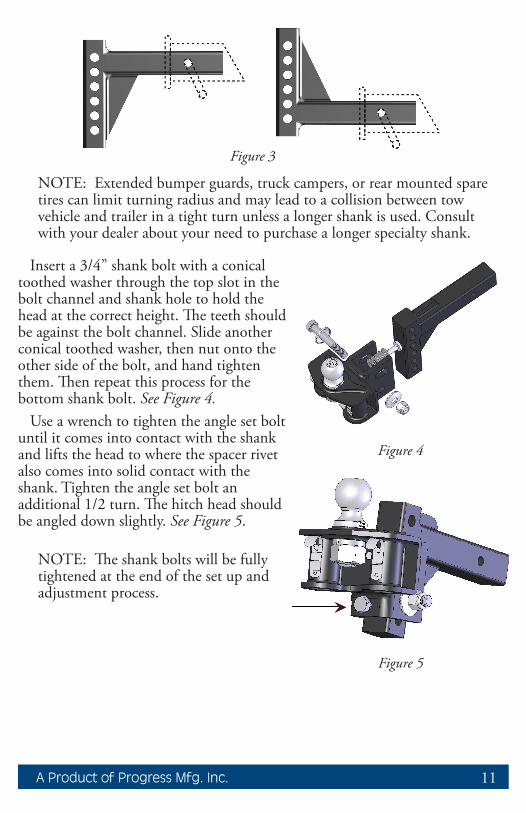
NOTE: Extended bumper guards, truck campers, or rear mounted spare tires can limit turning radius and may lead to a collision between tow vehicle and trailer in a tight turn unless a longer shank is used. Consult with your dealer about your need to purchase a longer specialty shank.
Insert a 3/4” shank bolt with a conical toothed washer through the top slot in the bolt channel and shank hole to hold the head at the correct height. The teeth should be against the bolt channel. Slide another conical toothed washer, then nut onto the other side of the bolt, and hand tighten them. Then repeat this process for the bottom shank bolt. See Figure 4.
Use a wrench to tighten the angle set bolt until it comes into contact with the shank and lifts the head to where the spacer rivet also comes into solid contact with the shank. Tighten the angle set bolt an additional 1/2 turn. The hitch head should be angled down slightly. See Figure 5.
NOTE: The shank bolts will be fully tightened at the end of the set up and adjustment process.
Figure 4
Figure 5
Figure 3

12 FastwayTrailer.com
Step 4 - Sway Bracket Assembly Set Up:
Measure from the center of the coupler along the outside of the trailer frame, and place a mark at 27” on both sides. This is the center mark for the sway bracket assembly. See Figure 6a.
Check around the trailer frame and make sure that there are no gas lines, brake lines, or electrical wiring that could be affected by the installation of the link plates. If so, make sure these are re-routed or avoided and will not be disrupted or damaged by the link plate installation.
In some cases where there is an obstruction at 27” that cannot be avoided, the link plates may be moved forward up to a minimum distance of 24” from the center of the coupler.
NOTE: For trailers with an obstruction that does not allow installation at 24”-27”; if the tongue weight of the trailer is less than 800 lbs., the brackets may be moved forward down to a minimum of 20” on center. Be aware that moving the bracket assembly forward can alter the stiffness of the ride and the weight distribution set-up. Re-adjust the setup as necessary to get good weight distribution.
If the sway bracket assembly is moved forward more than the standard 24” you must also check to make sure the ends of the spring arms will not hit the sides of the trailer frame in a tight turn. See Figure 6b. Also check that the spring arm does not bind between the L-pin and L-bracket. If either of these issues occur, the bracket assembly must be moved backward until there is no binding or frame interference in tight turns.
24” m
in /
27” m
ax
Figure 6a
Figure 6b

13A Product of Progress Mfg. Inc.
Identify the coupler style that most closely matches your trailer. See Figure 7.
Top-mount: Place your link plates so that the single hole is above the frame, and the L-bracket studs are toward the top of the frame. See Figure 8a.
Bottom-mount: Install your link plates ‘upside-down’ by placing your link plates so that the single hole is below the frame, and the L-bracket studs are toward the bottom of the frame. See Figure 8b.
Thread a 1/2” x 4” bolt through the single hole of the outside and inside link plates from the outside in. The head of the bolt should be against the outside link plate with the threads to the inside. Slide a lock washer on, then thread a nut onto end of bolt a few turns. Slide the link plates over the frame as shown so that the L-bracket studs are facing outward. Thread the second bolt through the link plate holes closest to the trailer frame with the head on the outside, and thread the lock washer and nut onto it from the back side.
Pinch the inside and outside link plates tight to the trailer frame so that both lay flat against the frame. Inside link plates are sometimes slightly bowed. If this is the case, the center of the bow should be placed toward the trailer frame so that as they are tightened they flatten out against the frame.
Continue holding them in place while you hand tighten both nuts. Use wrenches to finish tightening the link plate bolts until they are snug, alternating from top to bottom 1/2 turn at a time. These should be torqued to 65 ft-lbs. Improper installation or under tightening may cause link plates to “walk” along the frame. See Figure 9.
Figure 8bFigure 8a
Figure 9
Correct Incorrect
Top-mount Bottom-mount Figure 7

14 FastwayTrailer.com
Slide the L-brackets onto the link plate studs with the spring arm plate facing away from the trailer. For the initial setup, leave two (2) holes showing at the top above the studs and two (2) below. They may need to be adjusted up or down later. Thread on the nylock nuts and tighten them. See Figure 10. When weight distribution setup is complete, torque the L-bracket nuts to 75 ft-lbs.
Step 5 - Install Spring Arms:
Apply a thin layer of bearing grease to the shorter, notched end of one of the spring arms. Either arm will fit either side of the hitch, they are not side-specific. See Step 10 - Regular Maintenance.
Push the arm up into the bottom of the hitch head. Make sure that it seats well, and that the keeper tab snaps into place to hold the arm in the head. See Figure 11.
Repeat for the 2nd arm.Arms can be removed by either pulling on
the keeper tab to release them, or by swinging them outward to be perpendicular to the tow vehicle. At this point, the arm will drop freely from the head without having to manually pull the keeper tab.
Frequently apply a small amount of bearing grease to the head end of the spring arms, and up inside the hitch head to reduce wear and make insertion easier. This will also help reduce hitch noise.
It is not necessary to apply lubricant to the joint where the spring arms rest on the L-bracket. This may decrease the amount of friction at this joint which could prevent the hitch from dampening trailer sway as well as possible.
Step 6 - Weight Distribution Setup:
Use the following guidelines to set up and adjust your e2 hitch for weight distribution. Good weight distribution is a critical component of the e2 hitch setup. A hitch that is set up poorly for weight distribution will not perform like one that is set up well. Every tow vehicle and trailer combination will react differently to weight distribution.
To correctly set up weight distribution you must take 3 measurements at
Figure 11
Keepertab
Figure 10

15A Product of Progress Mfg. Inc.
different times on your tow vehicle. First, measure without the trailer coupled. Next, measure with the trailer coupled, but with no weight distribution. Third, measure coupled with the weight distribution bars tensioned.
Start by measuring the distance from the ground to the wheel well directly above the front axle with the trailer uncoupled. See Figure 12. Record this on Line A of the Weight Distribution Setup Table.
Back the tow vehicle to the trailer and lower the coupler onto the ball. Lock the coupler and retract the tongue jack until it raises off the ground about 1” so that the full tongue weight of the trailer is resting on the hitch.
Measure the tow vehicle height again, exactly above the front axle, to the same point that you measured to earlier when uncoupled. Record this on Line B of the weight distribution setup table above.
With the tow vehicle still coupled to the trailer, use the tongue jack to lift both vehicles until you can swing the spring arms into place over the L-brackets. See Figure 13.
If you reach the top of the jack before the spring arms will swing into position, you can use the Snap-up Lever to lift the spring arms up and onto the L-brackets. Use the L-pins to secure the spring arms on the L-brackets. See Figures 14a -14b.
Measure from ground to fender through the center-line of the axle.
Rear FrontFigure 12
Weight Distribution Setup Table FRONT ExampleA Tow vehicle loaded for trip but still uncoupled from trailer 28”B Tow vehicle coupled but NO weight distribution 30”
Calculate height halfway between A and B (A+B)÷2= 29”
CTow vehicle coupled with weight distribution engaged. Should be at least halfway back to Line A. Higher than this may still be under adjusted. Lower than Line A is over adjusted. See Figure 19.
28”-29”Good__________
29”-30”Need More

16 FastwayTrailer.com
With the spring arms resting on the L-bracket and the trailer and tow vehicle in line with each other, check to make sure that there is a minimum of 3” from the end of the spring arms to the center of the link plates. See Figure 15. Move and re-tighten the link plates if necessary.
NOTE: Refer to Appendix B “Weight Dis-tribution Adjustments” on page 24 for a more detailed description of factors that influence weight distribution setup and adjustment.
Retract the tongue jack until all of the tongue weight is resting on the hitch. With the trailer coupled and weight distribution engaged, re-measure the front wheel well height from the ground in exactly the same place as before in this step. Record this new measurement on Line C of the Weight Distribution Setup Table on page 15.
3”minimum
Figure 15
Figure 13
Figure 14a Figure 14b

17A Product of Progress Mfg. Inc.
Step 7 - Weight Distribution Adjustments
WARNING
WARNINGWeight distribution is only one of many things that influence sway. The operator is responsible for making necessary adjustments to all contribut‑ing factors in order to minimize sway.
Good adjustment:You have most likely achieved good weight distribution adjustment if your
measurement on Line C of the weight distribution setup table shows that front wheel well measurement is at least halfway back to the original uncoupled measurement, and ideally, back down to as close to the original uncoupled measurement as possible.. See Line C on Weight Distribution Setup Table and Figure 16 below.
Figure 16
C halfway back with WD
A uncoupled
goodadjustment
needsmore
See Weight Distribution Setup Table on p. 15.
B coupled - no WD
18 FastwayTrailer.com
WARNING
WARNINGOver or under adjusted weight distribution decreases tow vehicle stability.
Under or Over Adjustment:If the hitch is transferring too little or too much weight, you must make
adjustments to the hitch setup. For changes during the initial setup we recommend adding or removing spacer washers first to try and keep the spring arms parallel with the trailer frame. In our experience, this can improve the performance of the sway brackets. It also gives you more adjustment options if needed later.
Once the maximum (9) or minimum (5) number of spacer washers has been reached, further adjustments can be made by raising or lowering the L-brackets. Minor adjustments later for changes in loading can usually be done by moving only the L-brackets.
NOTE: The distance from the tow vehicle rear axle to the hitch ball sig-nificantly affects how the tow vehicle reacts to weight distribution adjust-ments. The same washer or L-bracket change will have varying results on different vehicles.
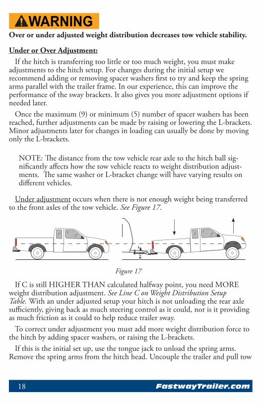
Under adjustment occurs when there is not enough weight being transferred to the front axles of the tow vehicle. See Figure 17.
If C is still HIGHER THAN calculated halfway point, you need MORE weight distribution adjustment. See Line C on Weight Distribution Setup Table. With an under adjusted setup your hitch is not unloading the rear axle sufficiently, giving back as much steering control as it could, nor is it providing as much friction as it could to help reduce trailer sway.
To correct under adjustment you must add more weight distribution force to the hitch by adding spacer washers, or raising the L-brackets.
If this is the initial set up, use the tongue jack to unload the spring arms. Remove the spring arms from the hitch head. Uncouple the trailer and pull tow
Figure 17

19A Product of Progress Mfg. Inc.
vehicle forward. Remove the hitch head and add a spacer washer. Repeat step 6 and 7 to re-adjust and check weight distribution.
If you have reached the maximum number of spacer washers, or if adjusting temporarily due to a change in vehicle loading, use the tongue jack to unload the spring arms. Raise the L-brackets 1 hole. Move the spring arms back over the L-brackets and retract the tongue jack. Re-measure the wheel wells and check for proper weight distribution.
Repeat Steps 6 and 7 until the measurements show that the hitch is distributing weight well.
Over adjustment occurs when there is too much weight being transferred to the front axles of the tow vehicle. See Figure 18.
If C is LOWER THAN A, you need LESS weight distribution adjustment. See Line C on Weight Distribution Setup Table.
Over adjustment is a very dangerous situation where loss of control and jack-knifing is possible, especially in wet or slick road conditions.
To correct over adjustment you must take some of the weight distribution force out of the hitch by removing spacer washers, or lowering the L-brackets.
If this is the initial set up, use the tongue jack to unload the spring arms. Remove the spring arms from the hitch head. Uncouple the trailer and pull vehicle forward. Remove the hitch head and remove a spacer washer. Repeat Steps 6 and 7 to re-adjust and check weight distribution.
If you have reached the minimum number of spacer washers, or if adjusting temporarily due to a change in vehicle loading, use the tongue jack to unload the spring arms. Lower the L-brackets 1 hole. Move the spring arms back over the L-brackets and retract the tongue jack. Re-measure the wheel wells and check for proper weight distribution.
Repeat Steps 6 and 7 until the measurements show that the hitch is distributing weight well.
Figure 18
20 FastwayTrailer.com
Step 8 - Trailer Angle Adjustment:
After achieving a good weight distribution setup you may need to adjust the attitude (angle) of the trailer. Step back and look at the trailer to see if the front appears to be tipped up or down excessively.
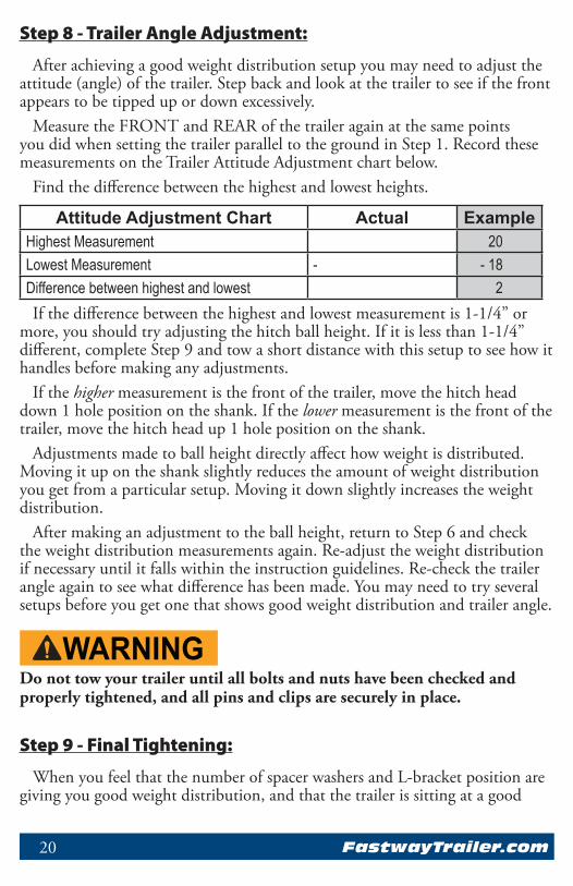
Measure the FRONT and REAR of the trailer again at the same points you did when setting the trailer parallel to the ground in Step 1. Record these measurements on the Trailer Attitude Adjustment chart below.
Find the difference between the highest and lowest heights.
Attitude Adjustment Chart Actual ExampleHighest Measurement 20Lowest Measurement - - 18Difference between highest and lowest 2If the difference between the highest and lowest measurement is 1-1/4” or
more, you should try adjusting the hitch ball height. If it is less than 1-1/4” different, complete Step 9 and tow a short distance with this setup to see how it handles before making any adjustments.
If the higher measurement is the front of the trailer, move the hitch head down 1 hole position on the shank. If the lower measurement is the front of the trailer, move the hitch head up 1 hole position on the shank.
Adjustments made to ball height directly affect how weight is distributed. Moving it up on the shank slightly reduces the amount of weight distribution you get from a particular setup. Moving it down slightly increases the weight distribution.
After making an adjustment to the ball height, return to Step 6 and check the weight distribution measurements again. Re-adjust the weight distribution if necessary until it falls within the instruction guidelines. Re-check the trailer angle again to see what difference has been made. You may need to try several setups before you get one that shows good weight distribution and trailer angle.
WARNING
WARNINGDo not tow your trailer until all bolts and nuts have been checked and properly tightened, and all pins and clips are securely in place.
Step 9 - Final Tightening:
When you feel that the number of spacer washers and L-bracket position are giving you good weight distribution, and that the trailer is sitting at a good

21A Product of Progress Mfg. Inc.
attitude, tighten all of the nuts and bolts securely. With the weight distribution engaged, begin with the angle set bolt, and tighten it until it comes back into solid contact with the shank plus 1/4 turn. Uncouple the trailer, then tighten all other bolts and nuts to the proper torque specs. Tighten both 3/4” shank bolts to 250 ft‑lbs. torque.
Double check the nuts holding the L-brackets to make sure they are tight, and also the bolts holding the sway bracket assembly to the trailer to make sure they are secure. Bolts holding the bracket to the frame should be torqued to 65 ft‑lbs., and the nuts for the L-brackets should be torqued to 75 ft‑lbs.
You are now ready to take the trailer out for a tow. Re-couple the trailer, making sure the L-pins and clips on the sway brackets and the arm retainer pins in the hitch head are secure. Remember to connect the safety brake cable, safety chains, and electrical cables. Make sure your trailer brake control is correctly adjusted. Retract the jack completely. Tow carefully at first and pay attention to how it feels. Follow the Troubleshooting Guide in Appendix A which suggests ways that can help improve your towing experience if needed.
Step 10 - Regular Maintenance:
The contact points of the head and spring arms, as well as the hitch ball, should be kept clean and well lubricated with a good quality bearing grease. See Figure 19. They should be cleaned and lubricated before each trip. Check for damage or abnormal wear at the beginning of each towing day and replace if necessary. Use a rag to clean dirt and road grit from all contact points regularly.
WARNING
WARNINGTowing with a loose angle set bolt for an extended period of time can cause abnormal stress on the hitch re‑sulting in accident, severe injury, and property damage.
All nuts and bolts should be checked before each towing day and re-tightened or replaced if necessary.
Pay special attention to the angle set bolt. There is a break-in period for each hitch and towing configuration. This period is not the same for every towing
Figure 19 Lubricate Here

22 FastwayTrailer.com
configuration. With use, the spacer washers and rivet may compact slightly leaving a small gap between the angle set bolt and the shank. The bolt should be checked frequently when your hitch is new and re-tightened until it comes in contact with the shank, plus 1/4 turn. You will notice that over time the need to re-tighten the angle set bolt will diminish, but you should still check it regularly before each towing day as part of your hook-up routine.
Store your hitch out of the weather when not in use. Keep it clean and free from rust. From time to time, use a good quality rust inhibiting spray paint to touch up the finish and keep it looking good. Do not paint over the warning stickers. If the warning stickers become worn or unreadable, contact Progress Mfg. Inc. for free replacements.Noise:
Towing noise is often an indication that your hitch needs to be cleaned and/or lubricated. Clean and grease your hitch as recommended. Following this process should eliminate most of the noise coming from the hitch.
If after lubricating the hitch you still experience some noise do not be alarmed. This is generally caused by the friction between the spring arms and L-brackets, which means that your e2 hitch is working as it should to help control sway.Customer Support:
For customer support, replacement parts, and accessories we recommend that you visit your local dealership that is familiar with Fastway® e2 products whenever possible. If at any time you need customer support and are unable to reach a dealership, please call our toll free customer support line at 877-523-9103, or visit us online at FastwayTrailer.com.
23A Product of Progress Mfg. Inc.
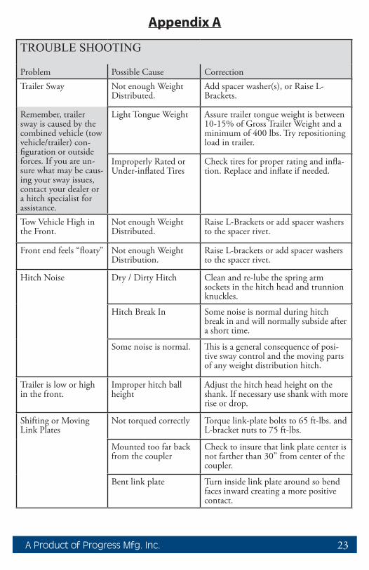
TROUBLE SHOOTING
Problem Possible Cause CorrectionTrailer Sway Not enough Weight
Distributed.Add spacer washer(s), or Raise L-Brackets.
Remember, trailer sway is caused by the combined vehicle (tow vehicle/trailer) con-figuration or outside forces. If you are un-sure what may be caus-ing your sway issues, contact your dealer or a hitch specialist for assistance.
Light Tongue Weight Assure trailer tongue weight is between 10-15% of Gross Trailer Weight and a minimum of 400 lbs. Try repositioning load in trailer.
Improperly Rated or Under-inflated Tires
Check tires for proper rating and infla-tion. Replace and inflate if needed.
Tow Vehicle High in the Front.
Not enough Weight Distributed.
Raise L-Brackets or add spacer washers to the spacer rivet.
Front end feels “floaty” Not enough Weight Distribution.
Raise L-brackets or add spacer washers to the spacer rivet.
Hitch Noise Dry / Dirty Hitch Clean and re-lube the spring arm sockets in the hitch head and trunnion knuckles.
Hitch Break In Some noise is normal during hitch break in and will normally subside after a short time.
Some noise is normal. This is a general consequence of posi-tive sway control and the moving parts of any weight distribution hitch.
Trailer is low or high in the front.
Improper hitch ball height
Adjust the hitch head height on the shank. If necessary use shank with more rise or drop.
Shifting or Moving Link Plates
Not torqued correctly Torque link-plate bolts to 65 ft-lbs. and L-bracket nuts to 75 ft-lbs.
Mounted too far back from the coupler
Check to insure that link plate center is not farther than 30” from center of the coupler.
Bent link plate Turn inside link plate around so bend faces inward creating a more positive contact.
Appendix A

24 FastwayTrailer.com
Appendix BWeight Distribution Adjustments:
You should carefully consider the following items and their effects when setting up initially and when adjusting your hitch before each trip:
• Vehicle wheel base: Shorter wheelbase vehicles react farther and faster than longer wheelbase vehicles to weight distribution adjustments.• Vehicle suspension: Soft suspensions, such as an SUV will react farther and faster to weight distribution adjustments than stiff suspensions like a 3/4 ton pickup. For a smoother ride, some vehicle suspensions are designed to be very soft with the first few pounds of payload, and to then stiffen as the load increases. This means that initially the springs move a long way with very little weight applied, then later move much less, even with a significant change in applied weight.• Trailer length: Longer trailers will try to force distributed weight forward to the tow vehicle before absorbing it into the trailer suspension. Shorter trailers absorb more of the distributed weight into their own suspensions.• Tongue weight: To operate effectively, your tongue weight should be at least 10% of the gross trailer weight. This provides the sway resisting friction force on the L-brackets of the hitch that give it the ability to resist movement and thus to resist trailer sway. It is also an indication that the center of gravity of the trailer is slightly forward of the axles, which helps provide stability and avoid sway.• Trailer loading: This is one of the most significant factors that influences trailer sway. Most trailers are designed to have a tongue weight of between 10% and 15% of the overall trailer weight. Always follow the trailer manufacturer’s guidelines for tongue weight. Trailers that are “back-end heavy” can often cause trailer sway. Trailer loading changes tongue weight dramatically, and loading can change dramatically from one trip to the next, or even during the course of a short weekend trip.For example, full water and propane tanks that are tongue weight when you leave can become full waste tanks that subtract tongue weight for the return trip. Shifting just 40 gallons of water from the front to the back of your trailer can change 330 lbs. of positive tongue weight to 330 lbs. of negative tongue weight. Toy haulers without toys are designed to have very heavy dry (empty) tongue weights so that when they are loaded with toys they become a more balanced load.

25A Product of Progress Mfg. Inc.
Cargo carriers, bike racks, and second trailers attached to the rear bumper of a trailer add weight to the rear of the trailer that automatically subtracts tongue weight. We recommend that you do not add weight of any form to the rear bumper of your trailer. We also recommend that you do not tow a 2nd trailer under any circumstance.
• Trailer coupled attitude: Attitude refers to the angle that the trailer is tipped to. It is generally accepted that a trailer should be towed sitting parallel to the ground, or with the front (coupler) tipped slightly down. The front tipped too far up or down may be an indication of improper trailer loading, or a need to adjust the ball height or weight distribution settings.• Vehicle weight ratings: Each trailer and tow vehicle has a maximum Gross Vehicle Weight Rating (GVWR). Never exceed these ratings. The tow vehicle and towing equipment, including receiver, shank, hitch, and hitch ball all have maximum weight ratings for tongue weight and trailer weight. Never exceed any of these ratings.
WarrantyLimited 10 Year Warranty: Progress Mfg. Inc. warrants the e2™ hitch against latent defects in materials and workmanship under normal use and service, ordinary wear and tear is excepted, to the original owner for a period of 10 years from the first date of purchase at retail up to the value of its original purchase price. If this product is latently defective it will be replaced or repaired when a proper return authorization is obtained and the product is returned with transportation charges prepaid to Progress Mfg. Inc. Progress Mfg. Inc. shall not be required to replace or repair any products damaged as a result of improper installation, alteration, unreasonable use, or improper maintenance including, without limitation, loading the product beyond the factory rated load capacity. This warranty does not include labor charges nor does it include transportation charges for returning the product to the consumer. To the extent allowed by law, Progress Mfg. Inc. shall not be liable for any incidental, consequential, or any other damages including, without limitation, breach of any implied warranty, merchantability, or fitness for a particular purpose of any e2 product. In no event shall Progress Mfg. Inc. be liable for any damages other than the replacement or repair of the affected part. Authorization and warranty procedure may be obtained by calling Progress Mfg. Inc. customer service at 877-523-9103.Submit your warranty registration online at FastwayTrailer.com.

26 FastwayTrailer.com
FAQ
Q: How often do I need to adjust the angle set bolt?
A: This bolt only needs to be tightened if you notice a gap between the end of it and the hitch shank. It should be checked more frequently when your hitch is new. Include it as part of your routine when preparing to tow. See Step 10 - Regular Maintenance.
Q: Can I back up with the hitch hooked up and weight distribution engaged?
A: Yes, you don’t have to remove the spring arms like you would an add-on sway bar to back up.
Q: Do I need to lube the hitch ball? How often?
A: Yes, use a good bearing grease. Anytime it’s looking a little dry, wipe the old grease and grit out of the coupler socket and off of the hitch ball, then put a good dab (about 1 teaspoon) of grease on the hitch ball before coupling up. This will protect the hitch ball and coupler as well as eliminate some towing noise.
Q: Can I use an aftermarket airbag suspension kit with the e2 hitch?
A: Yes. Just make sure you air them up to the pressure you want to tow with before setting up the hitch for weight distribution. Filling air bags after the hitch has been set up usually causes the weight distribution to decrease, even though it looks like the back of the tow vehicle is not sagging.
If your tow vehicle came with a stock auto leveling system (air bags), follow the directions in Step 1 - Getting Things Ready.

27A Product of Progress Mfg. Inc.
NOTES
_____________________________________________________________
_____________________________________________________________
_____________________________________________________________
_____________________________________________________________
_____________________________________________________________
_____________________________________________________________
_____________________________________________________________
_____________________________________________________________
_____________________________________________________________
_____________________________________________________________
_____________________________________________________________
_____________________________________________________________
_____________________________________________________________
_____________________________________________________________
_____________________________________________________________
_____________________________________________________________
_____________________________________________________________
_____________________________________________________________
_____________________________________________________________
_____________________________________________________________
_____________________________________________________________
_____________________________________________________________
_____________________________________________________________
_____________________________________________________________
353 S. 1100 W. • Provo, UT 84601 • 877-523-9103ProgressMfg.com
All printed material copyright © 2010 - 2015 Progress Mfg. Inc. - All rights reserved.
E2OM_0915 Instruction Manual Part # BD094
TM
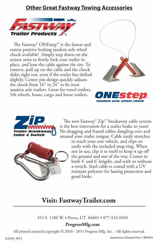
The Fastway® ONEstep™ is the fastest and easiest positive locking tandem axle wheel chock available! Simply step down on the scissor arms to firmly lock your trailer in place, and lean the cable against the tire. To remove, pull up on the cable and the chock slides right out, even if the trailer has shifted slightly. Center pin design quickly adjusts the chock from 16” to 24” to fit most tandem axle trailers. Great for travel trailers, 5th wheels, boats, cargo and horse trailers.
Other Great Fastway Towing Accessories
TM
Trailer BreakawayCable & Switch
The new Fastway® Zip™ breakaway cable system is the best innovation for a trailer brake in years! No dragging and frayed cables dangling over and around your trailer tongue. Cable easily stretches
to reach your tow vehicle, and clips on easily with the included snap ring. When not in use, clip it to itself to keep it up off the ground and out of the way. Comes in both 4’ and 6’ lengths, and with or without a switch. Steel cable is coated with a UV resistant polymer for lasting protection and good looks.
Visit: FastwayTrailer.com