Embed Size (px)
Citation preview
Owner’s Manual NanaWall WD65Wood Framed Top-Hung Folding System
This Owner’s Manual contains instructions on the installation, operation, maintenance and warranty of
the NanaWall WD65 Wood Framed Top-Hung Folding System. This manual is to be used by the installer
for installation and is to be kept by the Owner for reference. Replacement parts can be ordered directly
through NanaWall Systems.
If a screen unit is ordered, separate instructions are provided in the package with the screen unit. See
also screen installation considerations on page 4.
Nana Wall Systems, Inc.
100 Meadowcreek Drive #250
Corte Madera, CA 94925
800 873 5673
415 383 3148
Fax 415 383 0312
[email protected] nanawall.com
©2020 Nana Wall Systems, Inc.
NANAWALL WD65 OWNER’S MANUAL
2
Installation Instructions
The installation of the WD65 System requires a working
knowledge and experience in the use of tools, equipment
and methods necessary for the installation of aluminum
doors, windows, storefronts and/or partitions. This
practice assumes a familiarity with preparing a proper
and structurally sound opening, proper anchorage,
waterproofing, caulking and sealing and assumes
an understanding of the fundamentals of building
construction that affect the installation of large door
systems.
Highly recommended is using a NanaWall-trained independent installer, if available, or, at least, an installer who has some experience in installing NanaWall systems.
IMPORTANT: READ COMPLETE INSTRUCTIONS BEFORE BEGINNING INSTALLATION. INSTALL AS RECOMMENDED; OTHERWISE, THE UNIT MAY NOT FUNCTION PROPERLY AND ANY WARRANTY, WRITTEN OR IMPLIED, WILL BE VOID.
CAUTION:
As regulations governing the use of glazed windows,
doors, storefronts and/or partitions vary widely, it is the
responsibility of the building owner, architect, contractor
or installer to insure that products selected conform to
all applicable codes and regulations, including federal,
state and local. NanaWall Systems, Inc. can assume no
obligation or responsibility whatsoever for failure of the
building owner, architect, contractor or installer to comply
with all applicable laws and ordinances and safety and
building codes.
The WD65 system is shipped with all necessary
components. However, not included are screws, bolts,
shims, etc. to anchor the unit to the rough opening.
The frame is shipped knocked down and needs to be
assembled. Panels are pre-assembled with or without
glass, ready to be attached to the installed frame. In most
cases, all hinges, weather stripping, multiple locking, and
flat handles are pre- attached to the panels and frame
components.
DESCRIPTION OF SUPPLIED PARTS Check all parts carefully before assembly. Depending
on the model, some of these parts may already be
pre-installed on the panels. Check that the sizes of the
frame components and panels match with what was
ordered. In the small cardboard box attached to the
frame components that contains hinge pins and various
hardware, inspect the elevation drawing, indicating size,
configuration, and labeling of the unit ordered. For orders
with multiple units, do not mix and match panels and
frames, even if two units are exactly the same. Below is a
list of supplied parts
Always looking from inside.
• Left side jamb, labeled L, and right side jamb,
labeled R.
• Head jamb, labeled O, and sill, labeled U. (In some
instances the head jamb and sill may be in segments.)
• Pre-assembled panels: rollers, guides and locking
mechanism with flat handles are installed on the
panels. The number of panels depends on the model
ordered. The sequence of labeling of panels starts from the left with the left most panel labeled Panel 1. If supplied unglazed, panels have to be glazed before
being installed in the opening. See Appendix A: Glass
Installation and Glazing.
• A certain amount of hinge pins and set screw to
secure the hinge pins.
NANAWALL WD65 OWNER’S MANUAL
3
• Lever handles, other handles or other entry hardware
as ordered. These may be pre-attached to the panels.
• Panel holder – one for each swing door not attached
to a side jamb.
HANDLING OF COMPONENTS1. Upon receipt, inspect the shipment to ensure it is in
good condition.
2. Make sure that the small cardboard box with the
hinge pins and other hardware does not get lost.
3. Store in a clean and dry location and protect against
defacement or damage, especially to the edges of
panels.
4. Wood components should not be subject to extreme
or rapid changes in heat or humidity, such as forced
heating to dry out a building.
5. All wood surfaces including all edges (top, bottom and sides) should be completely sealed and finished promptly.
PREPARATION OF THE ROUGH OPENING For necessary clearance and adjustment space, make
rough opening about 3/4” wider and 3/8”- 1” higher than
the outside frame size of the unit ordered (check to
comply with applicable codes for maximum shim space
allowed, especially in high windload areas). It is important
that the opening be the correct size. Note that the
outside frame height of the unit ordered is measured
from the bottom of the sill and not from the finished floor.
Allowance must be made in height for the portion of the
sill that is below the measured opening.
IMPORTANT: Because of the large opening sizes
and the weight and movement of the panels, any
application should take into consideration the following:
1. The structural integrity of the header is critical for
proper operation. Vertical deflection of the header
under full live and dead loads should be the lesser of
L/720th of the span and 1/4”. Structural support for
lateral loads (both windload and when the panels are
stacked open) must also be provided.
2. A qualified engineer or architect should be used to
determine the proper construction details and header
to be used in your particular application.
3. THE ROUGH OPENING SHOULD BE LEVEL, PLUMB AND SQUARE AT ALL POINTS. THERE SHOULD BE NO UNEVENNESS OR BOWING. MAKE SURE THAT THE HEADER IS NOT TILTED OR TWISTED. THERE SHOULD BE NO BUMPS ON THE FLOOR. THE SIDES SHOULD BE IN THE SAME VERTICAL PLANE AND NOT OFFSET OF EACH OTHER. A TRANSIT AND OTHER SIMILAR PRECISE MEASURING EQUIPMENT SHOULD BE USED.
4. With a recessed sill, if concrete is to be poured after
the installation of the unit, the sill has to be securely
attached to the construction. If the sill is to be cast
in concrete, then an expansion gap with appropriate
material has to be created next to the sill.
5. With a low profile saddle sill, some resistance to
water infiltration may be achieved by installing drain
connections to the outside.
If any anchorage or drain connection holes are made through these drain channels, make sure that they are properly sealed to prevent any water leakage. The open ends of these drain channels at each end of the sill should also be properly sealed. Alternative anchoring
systems for the sill (without using screws through the
drain channels) are using L brackets attached to both
sides of the sill.
NANAWALL WD65 OWNER’S MANUAL
4
6. For better performance and protection, any exterior
folding system should be installed under an overhang
or with other similar protection.
7. For better performance it is recommended that
all dead loads such as upper levels, roof, etc. be
constructed before a unit is installed.
Properly flash and waterproof around the perimeter of the opening, especially at the sill. Make sure you seek proper professional advice for the appropriate construction needed for your particular application. DO not install unit in structures that do not allow for proper management/drainage of moisture.
To avoid future problems, do not install your unit until the
rough opening has been correctly prepared.
INSTALLATION CONSIDERATIONS IF THE SCREEN CLASSIC/ONE IS TO BE INSTALLED FOR THE NANAWALL UNIT
1. There must be an adequate frame by others at the
top and sides to which the Screen Classic/ONE is to
be attached. Although there is not much weight or
load from the Screen Classic/ONE, the frame must
not sag or deflect.
2. The bottom rail would need to be attached to the top
of the finished floor. The installation of the Screen
Classic/ONE may need to be delayed until the
finished floor is installed.
3. If the finished floor is higher than the bottom of
the NanaWall sill, the height of the Screen Classic/
ONE will need to be shorter than the height of the
NanaWall unit to allow for the difference in height
between the bottom of the NanaWall unit and the
finished floor.
4. To allow for stacking of the Screen Classic/ONE
beyond the NanaWall opening, the width of the
Screen Classic/ONE will need to be wider.
5. f the width of the Screen Classic/ONE is the same as
the NanaWall unit and if the header and wall are wide
enough, they can be used as the frame for the Screen
Classic/ONE. If not, a separate frame will be needed. It
could be attached to the header and wall.
6. Please note that if a separate frame for the Screen
Classic/ONE is made, please make sure that there are
no gaps between the frame and wall that will allow
any bugs to pass through.
7. Sufficient distance must be allowed between the Screen Classic/ONE and NanaWall units to allow clearance for any handles on the units. The Screen Classic/ONE must also clear the sill of the NanaWall unit.
8. Please see the separate Installation Manual of the
Screen Classic/ONE.
NANAWALL WD65 OWNER’S MANUAL
5
WOOD FINISHING AND MAINTENANCE RECOMMENDATIONS
NanaWall wood framed systems are shipped with a factory
applied layer of a water born translucent coat of sand
sealer or primer, which is an acrylic-copolymer-dispersion
from Sikkens (www.nam.sikkens.com). NanaWall aluminum
clad wood framed systems are shipped with a similar
additional coat. These factory applied coatings are not a sufficient and adequate protection from the elements and at least two coats of a final finish need to be applied in the field.
IMPORTANT: Immediately upon receipt of the unit
and prior to installation and exterior exposure to
weather elements, all wood surfaces including all
edges (top, bottom and sides) should be completely
sealed and must be protected with a good quality
finish. Before installation, keep the units in a dry
and clean location, store and stack them properly
to avoid twisting or warping of the panels and
frame components.
To complete the wood surface treatment use compatible finish material. If you think the product that you are
intending to use is not compatible, then completely
remove all pre-applied coats by chemical stripping
(please follow the direction of the product) or by sanding
off. Do not use power wash or excessive water. Then apply
a good quality sealer or primer and continue applying the
necessary coats as recommended by the product you
have chosen.
CAUTION:
Not all available paints and stains, nor the customer’s
specific application requirements can be evaluated. Your
local paint professional should know of suitable finish
systems that give satisfactory results in your region. It is
highly recommended that top quality finishes be selected,
and the directions of the products be followed explicitly.
In general, the surface must be prepared by cleaning off
dust and any debris. With 180-220 grit sandpaper, sand
lightly and thoroughly all surfaces to be painted. Do not
use steel wool or silicon carbide type sandpapers. Then
clean the surfaces before applying paint, etc.
For best performance, a minimum of two topcoats should
be applied.
Always make sure that you apply the coatings on a hidden area before finishing the whole unit to make sure you are satisfied with the results.
Ensure not to apply the coating material on to hardware,
gaskets, glass, sealant or aluminum surfaces to maintain
proper product performance.
All damages or scratches during installation on the
surface coating should be immediately touched up.
WOOD SIMULATED DIVIDED LITES (SDL) It is recommend that after completing the surface
treatment of the SDL and after allowing for adequate
drying time, to seal the gaps between the SDL and glass
with a durable weather resistant caulking material, which
is compatible with the surface treatment material.
MAINTENANCE OF WOOD UNITS As a general guideline it is recommended that every
1/2 year or earlier, to inspect visually the surface
and if necessary re-finish in the same manner as
per instructions above . The timeframe may vary on
weathering, exposure conditions and altitude. Whenever
damage is visual, it should be repaired immediately.
NANAWALL WD65 OWNER’S MANUAL
6
UNIT INSTALLATION
The Installation of the folding unit is described in the
following categories:
A. FRAME ASSEMBLY AND INSTALLATION
B. PANELS AND FOLDING HARDWARE INSTALLATION
C. FINAL STEPS
A. FRAME ASSEMBLY AND INSTALLATION
It might be easier to drill the holes as descript in Step A6
before assembling the frame.
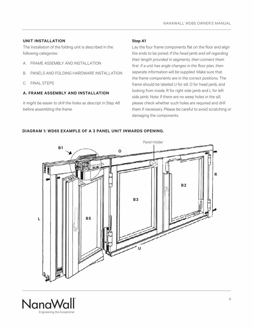
Step A1 Lay the four frame components flat on the floor and align
the ends to be joined. If the head jamb and sill regarding
their length provided in segments, then connect them
first. If a unit has angle changes in the floor plan, then
separate information will be supplied. Make sure that
the frame components are in the correct positions. The
frame should be labeled U for sill, O for head jamb, and
looking from inside, R for right side jamb and L for left
side jamb. Note: If there are no weep holes in the sill,
please check whether such holes are required and drill
them if necessary. Please be careful to avoid scratching or
damaging the components.
DIAGRAM 1: WD65 EXAMPLE OF A 3 PANEL UNIT INWARDS OPENING.
L
U
B1 O
B5
B3
B2
R
Panel Holder
NANAWALL WD65 OWNER’S MANUAL
7
Step A2 Assemble all frame parts as shown in Diagram 1. Do not
apply sealant to the corner joints yet.
Step A3 Do not screw the vertical side jambs to the head track nor
the sill. It has to be possible to slide the side jamb inwards
or outwards for adjustment.
Step A4 Be sure that appropriate flashing around the perimeter
of the opening is installed. Set the assembled frame into
the rough opening at the proper position relative to the
header. Make sure the direction is correct with respect to
inward or outward opening.
See Diagram 2 for Suggested Installation Details. Please
note that these are suggestions only and that these may
not be suitable in all applications.
Step A5 Temporarily secure the frame to the rough opening with
clamps.
Step A6 Looking on a standard installation, which is limited to
areas with a basic wind speed of not more than 90mph, in
a low rise building (max. 60feet roof height), Exposures B
or C and a non critical status. Fasteners locations should
start about 4” from the interior edge, drill holes for the
anchorage devices to connect the frame to the opening
at a spacing of not more than every 16” along the head
jamb and the sill. On the head jamb and sill an additional
fastener should be placed at the meeting point of panels
in the closed position and anchorage points every 4” in
the stacking area on either side. The spacing of the side
jamb should be about 14” starting at the bottom, using an
extra screw at the top. For installation that are beyond the above limitations, a structural engineer should be consulted for specific fastening requirements.
Use appropriate screws or other equivalent anchorage
devices depending on the adjacent substrate material
and construction. Make sure they are corrosion resistant.
Anchorage devices should penetrate or hold sufficiently
to the opening to withstand necessary structural loading.
Generally, for wood frame use #14 (1/4” diameter) wood
screws with 2-1/2” minimum embedment, for concrete
with a minimum compressive strength of 3,200 psi use
3/16” diameter ITW Tapcons (concrete screws) with
1-1/4” min. embedment. For masonry use 1/4” diameter
ITW Tapcons (masonry screws) with 1-1/4” embedment.
Standard installation into light gage steel substrates with
a minimum of 18 gage (0.0451“ thick) should have 1/4”
diameter type 410 stainless steel self drilling screws. Into
structural steel substrates thicker than 1/4” should be
predrilled and 1/4” diameter SAE Grade 2 bolts can be
used. Another option is to use type 410 stainless steel self
drilling screws. For this option first drill small pilot holes.
Make sure that the screw head with washer (if any) is
small enough to fit inside the slot in the middle of the
head jamb and sill; otherwise, it will interfere with the
rolling of the running carriages.
Anchor through the center of the groove but make
sure the screw or bolt head with washer bears on the
aluminum. To maintain the thermal break, use PVC or
nylon washers so that the screw heads do not bridge the
aluminum.
Make sure that the frame is level, plumb and square at
all points. There should be no unevenness or bowing.
If, for any reason, the floor is not level, shim with plastic
horseshoe shims to the highest point of the floor,
provided there is still enough clearance at the top. Place
plastic, horseshoe type shims tightly at every fixing point
between the frame profile and rough opening. Use hard plastic horseshoe shims only.
NANAWALL WD65 OWNER’S MANUAL
8
Step A7 Anchor the sill to the sub floor in correct relation to the
finish floor. Make sure that the sill is not tilted or twisted.
Make sure that all holes drilled through the sill are
properly sealed with silicone underneath and around
the screws.
All weep holes in the sill are not to be obstructed.
Make any necessary adjustments to level, plumb, and
square before proceeding on.
Step A8 Anchor the side jambs to studs or walls in the same
manner. Make sure that the jambs are plumb and straight.
Step A9 Anchor the head jamb through the pre-drilled holes and
shims. Make sure that the head jamb is level.
IMPORTANT: Make sure no shims are forced to
ensure that frame sections are not bowed.
Check frame constantly to be certain that it is level,
plumb and square. A transit and other similar precise
measuring equipment should be used to make these
determinations.
Step A10
IMPORTANT: Make sure that all the surfaces of the
upper and lower tracks are clean and free of any
debris, especially, cuttings from drilled holes.
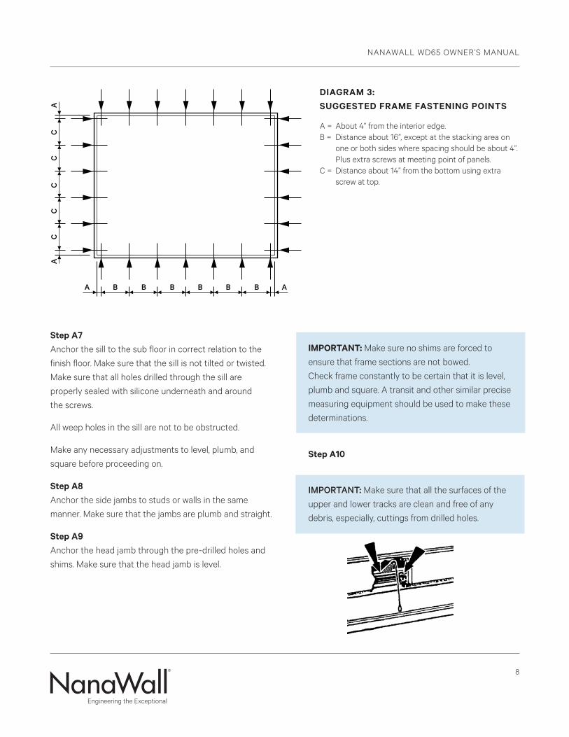
DIAGRAM 3:SUGGESTED FRAME FASTENING POINTS
A = About 4” from the interior edge. B = Distance about 16”, except at the stacking area on one or both sides where spacing should be about 4”. Plus extra screws at meeting point of panels.C = Distance about 14” from the bottom using extra screw at top.
NANAWALL WD65 OWNER’S MANUAL
9
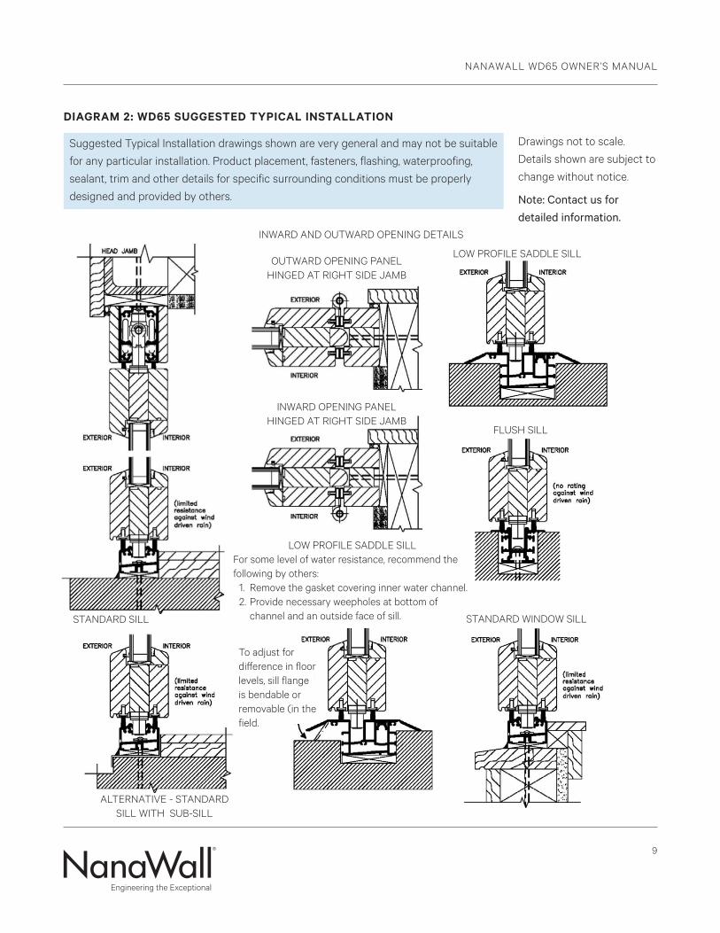
DIAGRAM 2: WD65 SUGGESTED TYPICAL INSTALLATION
INWARD AND OUTWARD OPENING DETAILS
Suggested Typical Installation drawings shown are very general and may not be suitable
for any particular installation. Product placement, fasteners, flashing, waterproofing,
sealant, trim and other details for specific surrounding conditions must be properly
designed and provided by others.
Drawings not to scale.
Details shown are subject to
change without notice.
Note: Contact us for detailed information.
OUTWARD OPENING PANEL HINGED AT RIGHT SIDE JAMB
INWARD OPENING PANEL HINGED AT RIGHT SIDE JAMB
STANDARD SILL STANDARD WINDOW SILL
LOW PROFILE SADDLE SILL
FLUSH SILL
ALTERNATIVE - STANDARD SILL WITH SUB-SILL
LOW PROFILE SADDLE SILLFor some level of water resistance, recommend the following by others: 1. Remove the gasket covering inner water channel. 2. Provide necessary weepholes at bottom of channel and an outside face of sill.
To adjust for difference in floor levels, sill flange is bendable or removable (in the field.
NANAWALL WD65 OWNER’S MANUAL
10
B. PANELS AND FOLDING HARDWARE INSTALLATION
IMPORTANT: Look for glass stops to determine the
interior side of a panel.
Step B1 Looking at the elevation drawing, note where the
installation slot in the head jamb is located. The slot can
be accessed by the removal of the approx. 12” small piece
of wood trim on the head track. Reach into the track to
slide the rod and open the plate. See Diagram 1.
Step B2 Start with the panel furthest away from the slot. If it is to
be hinged off the side jamb, align the hinges and insert
the proper hinge pins.
Do not force any hinge pins and do not hammer them all
the way in, let the knurling stick out.
If it is part of unhinged paired panels not hinged to the
side jamb, set lower guide that is pre-attached to the
bottom of the panel, in the lower track. Insert the upper
running carriage roller that is pre-attached on top of the
panel, through the slot in the head jamb.
Step B3 Again, looking at the elevation drawing, attach the next
panel needed to create a folding pair. Set the guide in the
lower track and insert the roller through the slot in the
head track. Slide the panel and align the hinges with the
first panel. Insert the hinge pins to create a folding pair.
If necessary, place temporary blocks under the panels to
assist in keeping the panels in a steady position.
After installation of each panel, check to make sure that
the panel is vertically straight.
Step B4 If there are additional panels to be attached to the folding
pair, close the pair by turning the handle 180°.
Step B5
Attach additional panels in the same manner.
C. FINAL STEPS Step C1 Attach handles and other hardware that have not been
pre-attached. Attach the profile cylinder (if any) to
the locking gear by inserting it into the lock hole and
attaching the set screw through the screw hole on the
gear located at the edge of the panel. Cut the set screw, if
needed, so it is not longer than 1-1/2” to 2” depending on
locking type.
Step C2
IMPORTANT: For swing panels not attached to a side
jamb, attach the panel holder to the top of the upper
rail of the adjacent panel. See Diagram 1. Follow the
specific instructions that are on the sheet in the panel
catch kit. The purpose of this is that the swing panel
should always be opened and engaged into the panel
holder before the folding panels are to be opened.
Step C3 Close and lock all panels into position.
Step C4 Check all horizontal joints:
Make sure the head jamb and sill are still level. Then
along the entire width of the opening, check the spacing
between the sill and each panel and the spacing between
the head jamb and each panel. Both spaces should be
about 5/16” along the entire length of the unit.
Check especially to see if the upper corner of a panel
where the running carriage is located is not higher than
the other corner of the panel. If it is slightly lower (not
more than 1/16”), it is okay. Proper spacing is critical for proper operation of the unit.
NANAWALL WD65 OWNER’S MANUAL
11
Step C5 Check all vertical joints:
Make sure that the side jambs are still vertically straight.
All vertical spacing between side jamb & panel rebate and
the join where swing panel meet swing panel should be
5/16”, spacing between panel and panel should be 3/8”.
Step C6 Adjustments can be made by sliding the vertical jamb.
See Diagram 1.
Step C7 Check that the system operates and functions properly.
The panels should be able to be moved easily by one
person without much effort (for not more than 6 panels
to one side) when opening or closing and all shoot bolts
should engage smoothly. If the panels do not move easily
or a lot of effort is needed, the indication is that the unit is
not properly installed. Correct any problems before finish
trimming.
Step C8 Install the hinge pins complete. Again check the
operation.
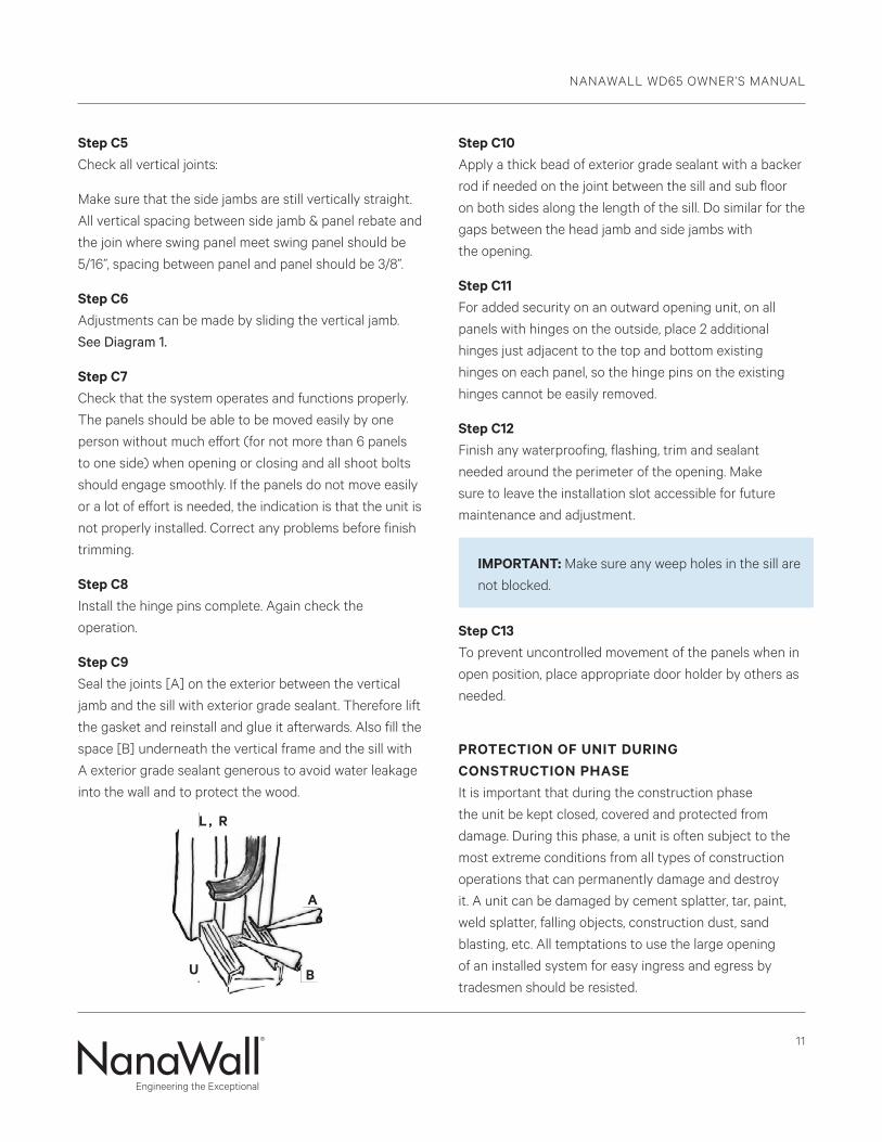
Step C9 Seal the joints [A] on the exterior between the vertical
jamb and the sill with exterior grade sealant. Therefore lift
the gasket and reinstall and glue it afterwards. Also fill the
space [B] underneath the vertical frame and the sill with
A exterior grade sealant generous to avoid water leakage
into the wall and to protect the wood.
Step C10
Apply a thick bead of exterior grade sealant with a backer
rod if needed on the joint between the sill and sub floor
on both sides along the length of the sill. Do similar for the
gaps between the head jamb and side jambs with
the opening.
Step C11 For added security on an outward opening unit, on all
panels with hinges on the outside, place 2 additional
hinges just adjacent to the top and bottom existing
hinges on each panel, so the hinge pins on the existing
hinges cannot be easily removed.
Step C12 Finish any waterproofing, flashing, trim and sealant
needed around the perimeter of the opening. Make
sure to leave the installation slot accessible for future
maintenance and adjustment.
IMPORTANT: Make sure any weep holes in the sill are
not blocked.
Step C13
To prevent uncontrolled movement of the panels when in
open position, place appropriate door holder by others as
needed.
PROTECTION OF UNIT DURING CONSTRUCTION PHASE It is important that during the construction phase
the unit be kept closed, covered and protected from
damage. During this phase, a unit is often subject to the
most extreme conditions from all types of construction
operations that can permanently damage and destroy
it. A unit can be damaged by cement splatter, tar, paint,
weld splatter, falling objects, construction dust, sand
blasting, etc. All temptations to use the large opening
of an installed system for easy ingress and egress by
tradesmen should be resisted.
L , R
A
B U
NANAWALL WD65 OWNER’S MANUAL
12
Operation And Maintenance Of NanaWall ProductsOPERATION OF A NANAWALL FOLDING UNIT
For opening and closing the folding system, please
observe the special notes on the following pages in as far
as they relate to your folding system.
When operating the folding system similar to any other door, please do not place your fingers between the panels/pivot points. You may hurt them!
Do not have anyone not properly trained on operation and children operate the unit.
Do not force the system if not operating properly. Please have it repaired as soon as possible by a qualified technician.
Anchor panels when in the open position to prevent uncontrolled movement, especially in windy conditions, that might cause damage and injury.
It is highly recommended that if not used, the NanaWall
folding unit be kept closed as much as possible, in order
to provide best security and weather resistance. When
closed, please engage all locking mechanisms fully.
The correct sequence of opening and closing of panels is
dependent on the configuration ordered. Panels must be
opened and closed in the right order.
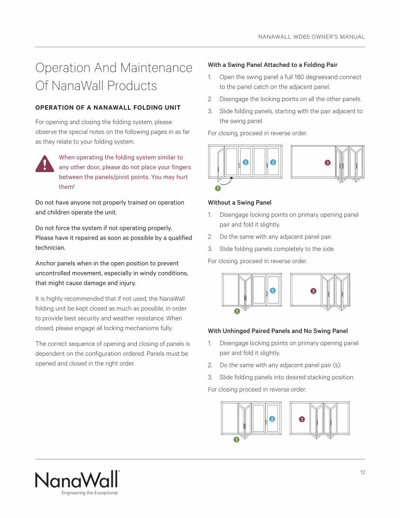
With a Swing Panel Attached to a Folding Pair
1. Open the swing panel a full 180 degreesand connect
to the panel catch on the adjacent panel.
2. Disengage the locking points on all the other panels.
3. Slide folding panels, starting with the pair adjacent to
the swing panel.
For closing, proceed in reverse order.
Without a Swing Panel
1. Disengage locking points on primary opening panel
pair and fold it slightly.
2. Do the same with any adjacent panel pair.
3. Slide folding panels completely to the side.
For closing, proceed in reverse order.
With Unhinged Paired Panels and No Swing Panel
1. Disengage locking points on primary opening panel
pair and fold it slightly.
2. Do the same with any adjacent panel pair (s).
3. Slide folding panels into desired stacking position.
For closing proceed in reverse order.
1
1
2 2 3
32
1
2 3
1
1
2 2 3
32
1
2 3
1
1
2 2 3
32
1
2 3
NANAWALL WD65 OWNER’S MANUAL
13
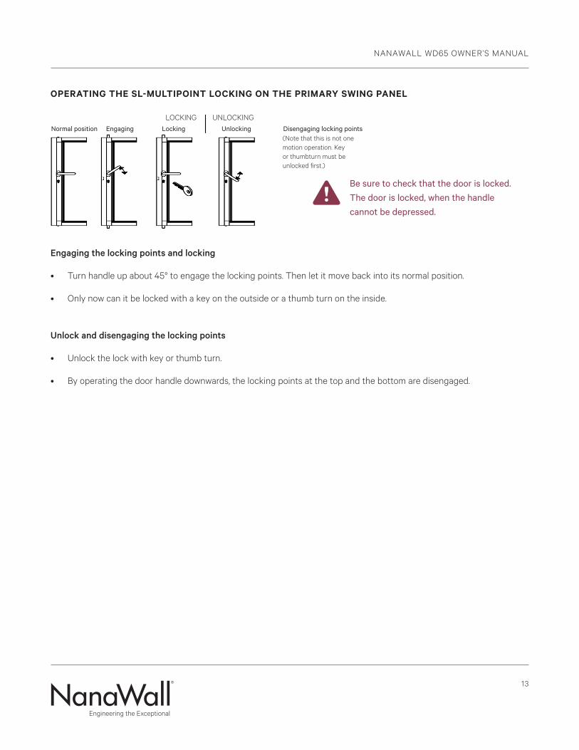
OPERATING THE SL-MULTIPOINT LOCKING ON THE PRIMARY SWING PANEL
Engaging the locking points and locking
• Turn handle up about 45° to engage the locking points. Then let it move back into its normal position.
• Only now can it be locked with a key on the outside or a thumb turn on the inside.
Unlock and disengaging the locking points
• Unlock the lock with key or thumb turn.
• By operating the door handle downwards, the locking points at the top and the bottom are disengaged.
UNLOCKING
(Note that this is not one motion operation. Key or thumbturn must be unlocked first.)
LOCKING
Be sure to check that the door is locked. The door is locked, when the handle cannot be depressed.
Normal position Engaging Locking Unlocking Disengaging locking points
NANAWALL WD65 OWNER’S MANUAL
14
RECOMMENDED MAINTENANCE OF NANAWALL PRODUCTS
Some General Considerations on all Projects:
1. It is important that the product is installed correctly.
A poorly installed unit will not function properly.
This will cause more abnormal force or stress on
the components and will lead to premature failure.
When operating the unit, the panels should generally
be able to be moved easily by one person (except
when there are very large panels or when there are
more than 6 panels folding to one side). All locking
points should engage smoothly. There should be no
rubbing on the floor and no binding. When the unit is
closed, the reveal between panels and head jamb and
between panels and sill should be consistent. There
should be no daylight seen from the inside. Please
have all problems corrected as soon as possible by a
qualified technician.
2. From time to time, due to building movement or
settlement, a unit may need to be adjusted by a
qualified technician to compensate for any building
change.
3. It is important that a unit is operated properly.
Locking points should be gently opened and closed
and not forced. Panels should be opened and
closed in the proper manner and sequence. See the
Operation section for proper operation.
4. Periodically check for worn or damaged components
and replace as soon as possible. A unit with
nonworking components will subject the other
components to increased stress and lead to
premature failure. A unit with worn or damaged
components will compromise the performance level
expected for air and water infiltration, structural
loading and forced entry.
5. Periodically, inspect the sealant/caulking on the
exterior perimeter of the unit. It is extremely
important that the sealant/caulking remains intact
and in good condition. Trim off any old, loose caulking
and seal any gaps with a good quality caulk.
6. Check that all weep holes are clean and clear of any
obstructions. Remove debris and other foreign bodies
which have dropped into the tracks in the head jamb
and sill immediately to prevent damaging the running
carriages and guide trolleys. Clean all components as
needed.
Check gaskets for proper seating and condition.
Remove dust and any deposits from these gaskets.
7. The finished aluminum or wood surface needs
periodic cleaning and maintenance. Its appearance
may be marred by harsh chemicals, abuse or neglect.
Frequency of cleaning depends on exposure and
needs. For aluminum surfaces, generally warm
soapy water should be sufficient. Stubborn stains
and deposits may be removed with mineral spirits.
For wood surfaces, superficial surface dirt can be
removed by washing with water and a soft-bristled,
long-handled brush. Heavier accumulations can
be removed with a mild solution of household
detergent. For all surfaces, aggressive alkaline or
acid cleaners should not be used. Excessive abrasive
rubbing should be avoided. Sealants and weather
stripping may be affected by strong organic solvents.
Superficial damage to the aluminum surface must be
touched up immediately with proper touch up paint.
8. If it is a wood product, the surface should be visually
inspected every six months or earlier, depending
on the exposure of the NanaWall unit. Periodically
repaint or restain the wood as needed. Exposure
to the environment will break down the finish and
compromise its protective features if not refinished.
NANAWALL WD65 OWNER’S MANUAL
15
See Finishing Recommendations in the Owner’s
Manual of the wood systems.
9. All hardware, hinges and handles should be
periodically cleaned with a soft cloth and mild
cleanser. Excessive abrasive rubbing should be
avoided. Please note that oil rubbed brass is a finish
that will develop its own unique patina over time.
10. About every six months, apply lubricant to all the
hinges and Teflon spray to the running carriages and
guiding trolleys.
SOME SPECIFIC SUGGESTED MAINTENANCE FOR COASTAL SALT WATER AND OTHER EXTREME ENVIRONMENTS:
Please note that the environment within one mile of a
sea coast can be extremely corrosive. Products installed
in this environment will typically deteriorate sooner than
products installed in a less severe environment.
1. Open and close completely a unit at least once a
week and inspect all surfaces.
a. Salt and other corrosive or abrasive materials
such as sand must not be allowed to build up on
any surfaces, including all hardware and sill.
b. The sill and head jamb tracks should be free from
all dirt and debris.
c. There should be no standing water in the track
in the sill.
d. All hardware should be intact and operating
properly.
2. All surfaces must be cleaned with a mild detergent
soap and fresh water at least every month and more
frequently if necessary.
a. After washing, the surface should be rinsed
thoroughly with clean water and allowed to dry.
b. For cleaning, do not use abrasive household
cleaners or materials like steel wool or hard
brushes that can wear and harm finishes.
c. Any glass cleaner used should not be allowed to
run down on any other surface.
3. Any breaches in the paint coating, such as scratches,
chips or areas of abrasion, must be repaired
immediately.
4. Every 3 months, thoroughly clean and dry all upper
and lower rollers and all hinges. Liberally apply
lubricant such as Teflon spray (no grease) on the
wheels and bearings of the rollers. Oil all hinges
including the hinge pin with light weight lubricating
oil or Teflon spray.
5. As with any painted surface exposed to corrosive
environments, every 6 months apply a wax to the
outside of the painted panel and painted track. If the
system includes corner connections make sure the
wax penetrates the connection joints.
16
GLASS INSTALLATION AND GLAZING
This section applies only if you need to install glass for
any reason or if glass setting blocks need to be adjusted.
Proper glass installation is critical, as, with the NanaWall
folding system, glass is a structural part of the panel.
Glass stops and glazing gasket are to be used for “dry”
glazing of each panel. Also needed are setting blocks. Use
glass setting blocks with varying thickness made from
hard plastic. Rubber setting blocks are not acceptable.
Width of setting blocks should be at least 1/8” wider than
the glass thickness and 1/16” to 1/8” less than the width of
the glazing pocket.
Glass, with appropriate dimensions, thickness and
specifications will be needed. Depending on the model,
widths of all glass panels may not be equal. Please note
that glass is required to be fully tempered unless the unit
is a window placed above a certain height from the floor.
Check with all applicable codes and regulations.
Float glass, including the glass components of insulated
glass, shall meet the current requirements of ASTM C
1306 “Standard Specifications for Flat Glass” for quality,
thickness and dimensional tolerances. Tempered float
glass shall meet the current requirements of ASTM C
1048 “Standard Specifications for Heat-Treated Flat
Glass - Kind HS, Kind FT Coated and Uncoated Glass.”
All tempered glass shall have a permanent logo, which
signifies Safety Commission 16 CFR-1201 and the safety
glass test requirements of ANSI Z 97.1 (current editions).
Insulating Glass shall meet the requirements of ASTM E
774, Class A, B or C.
Although glass installation with the “dry” glazing system
is relatively straight forward, it is recommended that an
experienced glazing contractor be used.
It is very important that the bracing direction and
placement of glass setting blocks on opposite diagonal
corners be correct. Setting blocks are to be placed only
at opposite diagonal corners with corners alternating with
each succeeding panel. This is necessary for the stability
and balance of the panels when in operation. If not
correctly braced, the unit will not operate properly.
The general rules for bracing are as follows:
• For a panel attached to a side jamb, the lower brace
should be at the lower corner closest to the side.
• For a panel with a running carriage, the lower brace
should be on the lower corner that is on the same
side as the running carriage.
• For a swing panel, the lower brace should be at the
lower corner away from the stile with the locking
hardware. See Diagram 1 for an example of setting
block locations.
Follow all proper applicable glass installation and glazing
techniques as recommended in the Flat Glass Marketing
Association (FGMA) “Glazing Manual” and “Sealant
Manual”. Always use suction cups to shift glass within an
opening. It would be best to install the glass on the panels
before they are installed in the opening. Panels can be laid
flat on sawhorses. If the panels are already installed, they
can still be glazed.
1. Close all panels and secure them with the multiple
point lock bolts. Start with a panel that is attached to
a side jamb or, in the case of unhinged pairs, closest
to a side jamb.
2. Remove all glass stops on the panel. Be sure to
protect the finish.
APPENDIX A NANAWALL WD65 OWNER’S MANUAL
17
APPENDIX A NANAWALL WD65 OWNER’S MANUAL
3. Measure both the vertical and horizontal dimensions
of the glass and the panel opening. Subtract the
vertical glass size from the vertical panel opening
size. Divide the difference by two. This will give the
nominal thickness of the setting block to use at
the top and bottom rails. Several setting blocks of
different thickness may need to be combined to
obtain the desired thickness. Do the same for the
horizontal dimension to obtain the thickness of the
setting block to use at the stiles.
4. Place a setting block (or combination of setting
blocks with desired thickness) on the bottom rail of
the panel opening such that it is about 2” from
the bottom corner as determined by the bracing
rules above.
5. Carefully place the glass in the opening, making
sure it rests on the setting block. With insulated
glass, make sure that both inner and outer panes are
supported evenly.
6. Place a second setting block in the same corner as
the first setting block, but in the vertical direction
along the stile such that it is about 2” above the
corner.
7. Place another setting block in the upper diagonal
corner vertically on the opposite stile in the same
manner. If necessary, apply a little adhesive that is
non-damaging to the glass edge seals such as Dow
Corning 791 silicone, to keep the vertical setting
blocks from slipping.
8. Place the last setting block on the upper rail on the
same corner as the other upper setting block. To get
a proper fit, shift the glass weight by lifting the panel
up with a plastic pry bar at the lower corner below the
upper setting block. These setting blocks should all
fit snugly but should not be forced.
Adjust the thickness of the glass setting blocks such
that the panel is slightly out of square. The upper
corner with the setting blocks should be about 1/16”
higher than the other corner.
If the panels are large, additional setting blocks may
be needed midpoint on the stiles, especially on a
swing panel.
9. For aluminum systems insert the glass stops so that
they snap into the panel profile. For wood systems
insert the glass stop firmly into position, so they are
flush with the panel. Nail to the inner side of the panel
with small finish nails. Start with the top and bottom
stops and then the sides.
10. Insert the glazing gasket in the space between the
glass and the glass stop. First, cut the gasket to a
length a little longer than the actual length of the
glass stop because gasket material may shrink at low
temperatures. Do not stretch or pull the gasket in any
manner. If necessary, use soapy water to lubricate the
gasket to make insertion easier.
11. Make sure that the stops are locked firmly and
securely into position and are flush with the rest of
the panel profile.
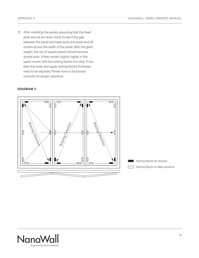
12. Repeat Steps 2 to 12 for each of the other panels.
Setting blocks for each succeeding panel must be
placed at diagonally opposite corners in the proper
sequence as set forth in Step 1. See Diagram 1 for an
example of a three panel unit.
18
APPENDIX A NANAWALL WD65 OWNER’S MANUAL
13. After installing the panels, assuming that the head
jamb and sill are level, check to see if the gap
between the panel and head jamb and panel and sill
is even across the width of the panel. With the glass
weight, the out of square panels should become
almost even. If they remain slightly higher in the
upper corner with the setting blocks it is okay. If not,
then the lower and upper setting blocks thickness
need to be adjusted. Panels have to be braced
correctly for proper operation.
DIAGRAM 1:
Setting blocks for tension
Setting blocks to keep distanceBracing D
irection
Bracing DirectionBr
acin
g D
irect
ion
Setting blocks for tension
Setting blocks to keep distance
Bracing Direction
Bracing DirectionBr
acin
g D
irect
ion
NanaWall Limited Warranty
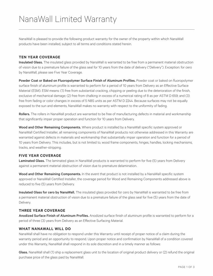
NanaWall is pleased to provide the following product warranty for the owner of the property within which NanaWall products have been installed, subject to all terms and conditions stated herein.
TEN YEAR COVERAGE Insulated Glass. The insulated glass provided by NanaWall is warranted to be free from a permanent material obstruction of vision due to a premature failure of the glass seal for 10 years from the date of delivery (“Delivery”). Exception: for cero by NanaWall, please see Five Year Coverage.
Powder Coat or Baked on Fluoropolymer Surface Finish of Aluminum Profiles. Powder coat or baked on fluoropolymer surface finish of aluminum profile is warranted to perform for a period of 10 years from Delivery as an Effective Surface Material (ESM). ESM means: (1) free from substantial cracking, chipping or peeling due to the deterioration of the finish, exclusive of mechanical damage; (2) free from chalking in excess of a numerical rating of 8 as per ASTM D 659; and (3) free from fading or color changes in excess of 5 NBS units as per ASTM D 2244. Because surfaces may not be equally exposed to the sun and elements, NanaWall makes no warranty with respect to the uniformity of fading.
Rollers. The rollers in NanaWall product are warranted to be free of manufacturing defects in material and workmanship that significantly impair proper operation and function for 10 years from Delivery.
Wood and Other Remaining Components. Where product is installed by a NanaWall specific system approved or NanaWall Certified Installer, all remaining components of NanaWall products not otherwise addressed in this Warranty are warranted against defects in materials and workmanship that substantially impair operation and function for a period of 10 years from Delivery. This includes, but is not limited to, wood frame components, hinges, handles, locking mechanisms, tracks, and weather-stripping.
FIVE YEAR COVERAGE Laminated Glass. The laminated glass in NanaWall products is warranted to perform for five (5) years from Delivery against a permanent material obstruction of vision due to premature delamination.
Wood and Other Remaining Components. In the event that product is not installed by a NanaWall specific system approved or NanaWall Certified Installer, the coverage period for Wood and Remaining Components addressed above is reduced to five (5) years from Delivery.
Insulated Glass for cero by NanaWall. The insulated glass provided for cero by NanaWall is warranted to be free from a permanent material obstruction of vision due to a premature failure of the glass seal for five (5) years from the date of Delivery.
THREE YEAR COVERAGE Anodized Surface Finish of Aluminum Profiles. Anodized surface finish of aluminum profile is warranted to perform for a period of three (3) years from Delivery as an Effective Surfacing Material.
WHAT NANAWALL WILL DO NanaWall shall have no obligation to respond under this Warranty until receipt of proper notice of a claim during the warranty period and an opportunity to respond. Upon proper notice and confirmation by NanaWall of a condition covered under this Warranty, NanaWall shall respond in its sole discretion and in a timely manner as follows:
Glass. NanaWall shall (1) ship a replacement glass unit to the location of original product delivery or (2) refund the original purchase price of the glass paid by NanaWall.
PAGE 1 OF 3
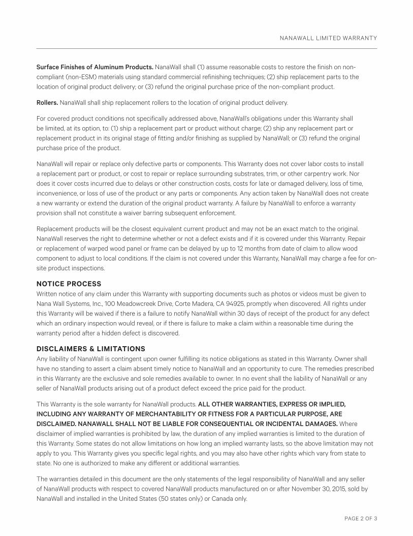
Surface Finishes of Aluminum Products. NanaWall shall (1) assume reasonable costs to restore the finish on non-compliant (non-ESM) materials using standard commercial refinishing techniques; (2) ship replacement parts to the location of original product delivery; or (3) refund the original purchase price of the non-compliant product.
Rollers. NanaWall shall ship replacement rollers to the location of original product delivery.
For covered product conditions not specifically addressed above, NanaWall’s obligations under this Warranty shall be limited, at its option, to: (1) ship a replacement part or product without charge; (2) ship any replacement part or replacement product in its original stage of fitting and/or finishing as supplied by NanaWall; or (3) refund the original purchase price of the product.
NanaWall will repair or replace only defective parts or components. This Warranty does not cover labor costs to install a replacement part or product, or cost to repair or replace surrounding substrates, trim, or other carpentry work. Nor does it cover costs incurred due to delays or other construction costs, costs for late or damaged delivery, loss of time, inconvenience, or loss of use of the product or any parts or components. Any action taken by NanaWall does not create a new warranty or extend the duration of the original product warranty. A failure by NanaWall to enforce a warranty provision shall not constitute a waiver barring subsequent enforcement.
Replacement products will be the closest equivalent current product and may not be an exact match to the original. NanaWall reserves the right to determine whether or not a defect exists and if it is covered under this Warranty. Repair or replacement of warped wood panel or frame can be delayed by up to 12 months from date of claim to allow wood component to adjust to local conditions. If the claim is not covered under this Warranty, NanaWall may charge a fee for on-site product inspections.
NOTICE PROCESS Written notice of any claim under this Warranty with supporting documents such as photos or videos must be given to Nana Wall Systems, Inc., 100 Meadowcreek Drive, Corte Madera, CA 94925, promptly when discovered. All rights under this Warranty will be waived if there is a failure to notify NanaWall within 30 days of receipt of the product for any defect which an ordinary inspection would reveal, or if there is failure to make a claim within a reasonable time during the warranty period after a hidden defect is discovered.
DISCLAIMERS & LIMITATIONS Any liability of NanaWall is contingent upon owner fulfilling its notice obligations as stated in this Warranty. Owner shall have no standing to assert a claim absent timely notice to NanaWall and an opportunity to cure. The remedies prescribed in this Warranty are the exclusive and sole remedies available to owner. In no event shall the liability of NanaWall or any seller of NanaWall products arising out of a product defect exceed the price paid for the product.
This Warranty is the sole warranty for NanaWall products. ALL OTHER WARRANTIES, EXPRESS OR IMPLIED, INCLUDING ANY WARRANTY OF MERCHANTABILITY OR FITNESS FOR A PARTICULAR PURPOSE, ARE DISCLAIMED. NANAWALL SHALL NOT BE LIABLE FOR CONSEQUENTIAL OR INCIDENTAL DAMAGES. Where disclaimer of implied warranties is prohibited by law, the duration of any implied warranties is limited to the duration of this Warranty. Some states do not allow limitations on how long an implied warranty lasts, so the above limitation may not apply to you. This Warranty gives you specific legal rights, and you may also have other rights which vary from state to state. No one is authorized to make any different or additional warranties.
The warranties detailed in this document are the only statements of the legal responsibility of NanaWall and any seller of NanaWall products with respect to covered NanaWall products manufactured on or after November 30, 2015, sold by NanaWall and installed in the United States (50 states only) or Canada only.
NANAWALL LIMITED WARRANTY
PAGE 2 OF 3
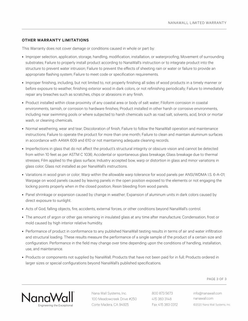
OTHER WARRANTY LIMITATIONS
This Warranty does not cover damage or conditions caused in whole or part by:
• Improper selection, application, storage, handling, modification, installation, or waterproofing; Movement of surroundingsubstrates; Failure to properly install product according to NanaWall’s instruction or to integrate product into thestructure to prevent water intrusion; Failure to prevent the effects of sheeting rain or water or failure to provide anappropriate flashing system; Failure to meet code or specification requirements.
• Improper finishing, including, but not limited to, not properly finishing all sides of wood products in a timely manner orbefore exposure to weather, finishing exterior wood in dark colors, or not refinishing periodically; Failure to immediatelyrepair any breaches such as scratches, chips or abrasions in any finish.
• Product installed within close proximity of any coastal area or body of salt water; Filoform corrosion in coastalenvironments, tarnish, or corrosion to hardware finishes; Product installed in other harsh or corrosive environments,including near swimming pools or where subjected to harsh chemicals such as road salt, solvents, acid, brick or mortarwash, or cleaning chemicals.
• Normal weathering, wear and tear; Discoloration of finish; Failure to follow the NanaWall operation and maintenanceinstructions; Failure to operate the product for more than one month; Failure to clean and maintain aluminum surfacesin accordance with AAMA 609 and 610 or not maintaining adequate cleaning records.
• Imperfections in glass that do not affect the product’s structural integrity or obscure vision and cannot be detectedfrom within 10 feet as per ASTM C 1036; Accidental or spontaneous glass breakage; Glass breakage due to thermalstresses; Film applied to the glass surface; Industry accepted bow, warp or distortion in glass and minor variations inglass color; Glass not installed as per NanaWall’s instructions.
• Variations in wood grain or color; Warp within the allowable warp tolerance for wood panels per ANSI/WDMA I.S. 6-A-01;Warpage on wood panels caused by leaving panels in the open position exposed to the elements or not engaging thelocking points properly when in the closed position; Resin bleeding from wood panels.
• Panel shrinkage or expansion caused by change in weather; Expansion of aluminum units in dark colors caused bydirect exposure to sunlight.
• Acts of God, falling objects, fire, accidents, external forces, or other conditions beyond NanaWall’s control.
• The amount of argon or other gas remaining in insulated glass at any time after manufacture; Condensation, frost ormold caused by high interior relative humidity.
• Performance of product in conformance to any published NanaWall testing results in terms of air and water infiltrationand structural loading. These results measure the performance of a single sample of the product of a certain size andconfiguration. Performance in the field may change over time depending upon the conditions of handling, installation,use, and maintenance.
• Products or components not supplied by NanaWall; Products that have not been paid for in full; Products ordered inlarger sizes or special configurations beyond NanaWall’s published specifications.
Nana Wall Systems, Inc.
100 Meadowcreek Drive #250
Corte Madera, CA 94925
800 873 5673
415 383 3148
Fax 415 383 0312
[email protected] nanawall.com
©2020 Nana Wall Systems, Inc.
NANAWALL LIMITED WARRANTY
PAGE 3 OF 3
Nana Wall Systems, Inc.
100 Meadowcreek Drive #250
Corte Madera, CA 94925
800 873 5673
415 383 3148
Fax 415 383 0312
[email protected] nanawall.com
©2020 Nana Wall Systems, Inc.
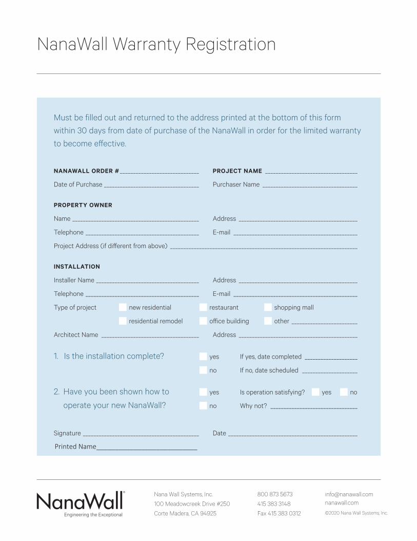
NanaWall Warranty Registration
Must be filled out and returned to the address printed at the bottom of this form
within 30 days from date of purchase of the NanaWall in order for the limited warranty
to become effective.
NANAWALL ORDER # ______________________________ PROJECT NAME ___________________________________
Date of Purchase ____________________________________ Purchaser Name ____________________________________
PROPERTY OWNER
Name ________________________________________________ Address _____________________________________________
Telephone ___________________________________________ E-mail _______________________________________________
Project Address (if different from above) _______________________________________________________________________
INSTALLATION
Installer Name _______________________________________ Address _____________________________________________
Telephone ___________________________________________ E-mail _______________________________________________
Type of project ■ new residential ■ restaurant ■ shopping mall
■ residential remodel ■ office building ■ other _________________________
Architect Name _____________________________________ Address _____________________________________________
1. Is the installation complete? ■ yes If yes, date completed ____________________
■ no If no, date scheduled _____________________
2. Have you been shown how to ■ yes Is operation satisfying? ■ yes ■ no
operate your new NanaWall? ■ no Why not? _________________________________
Signature ____________________________________________ Date _________________________________________________
Printed Name___________________________