Embed Size (px)
Citation preview

OWNER’S MANUAL
Low Profile Lifts(This manual is for machines manufactured
in May 2013 and newer)
SOUTHWORTH PRODUCTS CORPP.O. Box 1380, Portland, Maine 04104-1380
Phone (800) 743-1000 • (207) 878-0700 • Fax (207) 797-4734www.SouthworthProducts.com
E-mail: [email protected]
Model # __________________________________
Serial # ___________________________________
Placed in Service ___________________________
October 2016
Roll-ELiftMat

2 Roll-E Owner’s Manual
Southworth Products Corp is widely acknowledged as the leading maker of hydraulic lifts and materials-handling equipment. Southworth machines are rugged and reliable, and are designed to provide years of trouble-free service. The designs are based on extensive engineering experience. These are good reasons for specifying Southworth machines in your plant.
DO NOT EVER ATTEMPT
TO RAISE PLATFORM ORSCISSOR LIFT OPEN
MECHANICALLY(CRANE, HOIST, FORK TRUCK, ETC.)
THIS COULD DAMAGE THE CYLINDERS AND WILL SEPARATETHEM FROM THE BASE FRAME.
THE LIFT MUST BE SCISSORED OPEN USING THE
HYDRAULIC POWER UNIT.

SOUTHWORTH
Roll-E Owner’s Manual 3
ContentsINTRODUCTION ............................................................................ Page 4RESPONSIBILITY OF OWNERS AND USERS ........................................5SAFETY ................................................................................................... 6 Safety Regulations/Requirements ............................................... 6 Safe Servicing of the lift ............................................................... 6INSTALLATION INSTRUCTIONS ........................................................... 7 Preparation .................................................................................. 7 Assembly ......................................................................................7 Hydraulic Oil Specifications ..........................................................7OPERATING INSTRUCTIONS ................................................................11 Safety Label Compliance .............................................................12MAINTENANCE ..................................................................................... 14 Hazards .......................................................................................14 Routine Periodic Maintenance .....................................................14 Repacking Cylinders ....................................................................16 Replacing Leg Rollers ..................................................................17 Troubleshooting Warning and Check List ...................................18ORDERING REPLACEMENT PARTS.....................................................19WARRANTY .......................................................................Back of Manual
List of FiguresFigure 1 Engaging Maintenance Chocks ............................................... 6
Figure 2 Hydraulic Schematic ................................................................8
Figure 3 Wiring Diagram for Junction Box ..............................................9
Figure 4 Electrical Diagram ....................................................................9
Figure 5 Hydraulic Power Unit ..............................................................10
Figure 6 Safe Loading and Unloading ................................................. 11
Figure 7 Labels and Precautionary Markings .......................................13
Figure 8 Hydraulic Cylinder .................................................................16

4 Low Profile Lifts Owner’s Manual
Roll-E
IntroductionThis manual contains information to acquaint you with the safe and proper installation, use, and upkeep of the machine. You should ensure that this manual is available to personnel working with the machine and require its use by these personnel.
In the interest of safety, please read this entire manual carefully, and be familiar with its contents before you install, use, or service the machine. If you have any questions about any instructions in this manual, please contact your dealer or Southworth Products Corporation.
Southworth’s product warranty is provided in the back of this manual. This instruc-tion manual is not intended to be or to create any other warranty, expressed or implied, including any implied warranty of merchantability or fitness for a particular purpose, all of which are hereby expressly excluded.
As set forth more specifically in the product warranty. Southworth’s obligation under that warranty is limited to the repair or replacement of defective components, which shall be the buyer’s sole remedy. Southworth shall not be liable for any loss, injury, or damage to persons or property, nor for any direct, indirect, or con-sequential damage of any kind resulting from the lift table.

SOUTHWORTH
Low Profile Lifts Owner’s Manual 5
Responsibility of Owners and Users
Inspection and MaintenanceThe device shall be inspected and maintained in proper working order in accordance with Southworth’s owner’s manual.
Removal from ServiceAny device not in safe operating condition such as, but not limited to, excessive leakage, missing rollers, pins, or fasteners, any bent or cracked structural members, cut or frayed electric, hydraulic, or pneumatic lines, damaged or malfunctioning controls or safety de-vices, etc. shall be removed from service until it is repaired to the original manufacturer’s standards.
DeflectionIt is the responsibility of the user/purchaser to advise the manufacturer where deflection may be critical to the application.
RepairsAll repairs shall be made by qualified personnel in conformance with Southworth’s instruc-tions.
OperatorsOnly trained personnel and authorized personnel shall be permitted to operate the lift.
Before OperationBefore using the device, the operator shall have:
• Read and/or had explained, and understood, the manufacturer’s operating instruc-tions and safety rules.
• Inspected the device for proper operation and condition. Any suspect item shall be carefully examined and a determination made by a qualified person as to whether it constitutes a hazard. All items not in conformance with Southworth’s specification shall be corrected before further use of the equipment.
During OperationThe device shall only be used in accordance with this owner’s manual.
• Do not overload.• Ensure that all safety devices are operational and in place.
Modifications or AlterationsModifications or alterations to any Southworth industrial positioning equipment shall be made only with written permission from Southworth.

6 Low Profile Lifts Owner’s Manual
Roll-E
Safety Regulations/RequirementsThere is a built-in safety function in the safety frame. If the safety frame is touched on its way down, the table stops immediately. To continue lowering, the table has to be raised a little to be able to lower again.
The lift tables are always delivered with a control unit of the “deadman” type, which means that when the up or down button (or foot pedal on a footswitch control) is released the table will stop immediately.
Employee and employer must ensure that risk of trapping does not occur during installation use or maintenance of the lifting equipment.
1. Do not exceed the lifting capacity. 2. Check the action of the safety frames and the distance around the equipment to eliminate the risk trapping. 3. Precautionary labeling must be legible. 4. Check for damage due to overloading. 5. Check and maintain electric cables and hoses. 6. Check for oil leakage. 7. Ensure there is no debris under the lift. 8. When the load is traveling up or down the load should be evenly distributed. 9. Hazard – no hands or feet should ever be under the platform.
WARNING !Only authorized personnel should perform inspection or maintenance and service pro-cedures. Unauthorized personnel attempting these procedures do so at the risk of severe injury or death.
DANGER !Failure to properly adhere to lift blocking procedures is to risk the sudden and uncon-trolled descent of the lift during maintenance or inspection. A falling lift can cause severe injury or death.
This procedure describes the only factory-approved method of working under a lift. Follow these instruc-tions EVERY time you plan to reach or crawl beneath the lift to perform service or maintenance – no matter how momentary that might be.
If the factory-provided maintenance device is dam-aged or missing, stop immediately and consult the fac-tory for assistance. Southworth is not liable for your failure to use the approved maintenance devices and procedures that have been provided.
Safe Servicing of the lift
1. Any load must be removed from the lift prior to en-gaging the maintenance devices. These devices are designed to support an unloaded lift only. Fail-ure to remove the load from the lift prior to blocking could cause the failure of the maintenance device(s) and allow the lift to fall unexpectedly.
2. Raise the lift to its fully raised position. If you do not, the maintenance device(s) may not be able to be placed properly in their designed engaged position.
Maintenance Chock Disengaged (stored position)
Maintenance Chock Engaged
Figure 1: Engaging Maintenance Chocks

SOUTHWORTH
Low Profile Lifts Owner’s Manual 7
NOTICE!Do not try to move the lift by supporting the tilt platform. One end of the tilt platform is free.
Installation InstructionsPreparationBefore you start to use the unit, check for local codes and ordinances which may apply. It is your responsibility to obtain any necessary permits.Read all of these installation instructions carefully. Be sure to read and understand all of the warnings.The unit should only be used indoors, or it should be protected from the weather.
NOTICEDO NOT PULL THIS LIFT OPEN. This will damage the lift cylinders. This lift must be raised by the hydraulic power unit.
DANGER!The AC-powered unit has parts which carry 115 volts or more. This voltage can kill you! Don’t work with the electrical parts unless you are a qualified electrician.
WARNING!Protect the unit from rain or moisture. If the electrical parts in the power unit get wet, workers may be hurt by electrical shock. The electrical parts may fail if they are wet.
CAUTION!This unit has an electric motor that can create sparks. Don’t use the unit in an area where flammable gases may be present.
Remove the shipping material and remove the unit from the skid. You will need a crane or lift truck that can lift the unit safely.
3. Rotate the maintenance devices from their stored location and place them into the engaged position as shown in Figure 1.
4. Lower the lift until it makes complete contact with
the maintenance devices. Re-check to ensure that both devices are fully and securely engaged.
DANGER !If for any reason you are unable to lower the lift completely onto the maintenance device(s), stop immediately and consult the factory. Failure to properly use the factory approved maintenance devices could result in severe injury or death.
On the front of this manual, write down the model num-ber, serial number, and date the unit is placed in service. The location of the name plate is up under the platform.
Assembly
1. The lift must always be securely fixed to the floor with expander bolt or anchors.
2. Run the lift to its upper position and engage the maintenance device on both sides.
3. Lower the lift onto to maintenance device.
4. An electrician must make the installation of the electrical system if three phase.
5. Test the function of the safety frame on all sides.
6. Ensure the load is evenly distributed load.
7. The push button or foot switch should be installed to have a good view when the lift is moving.

8 Low Profile Lifts Owner’s Manual
Roll-E
Hydraulic Oil Specifications
If the lift will be used at normal ambient temperatures, Southworth supplies the unit with Citgo AW 32 oil. This may be replaced by any other good quality oil with 150 SSU at 100° F and rust and oxidation inhibitors and anti-wear properties.
If the lift will be used at ambient temperatures below 0°F, use aircraft hydraulic oil. Use Type 15 aircraft hydraulic oil.
The following are equivalent to CITGO AW32:
TYPE MANUFACTURER
DTE 24 ............................. EXXON/MOBILNUTO H32 ........................ EXXON/MOBILAMOCO AW32 .................. CHEVRON (AMOCO CO.)
NOTICE! It is very important to keep the hydraulic oil free of dirt, dust, metal chips, water, and other con-tamination. Most of the problems with hydraulic systems are caused by contamination in the oil.
Figure 2 Hydraulic Schematic

SOUTHWORTH
Low Profile Lifts Owner’s Manual 9
Figure 3 Wiring Diagram for Junction Box
Figure 4 Electrical Diagram

10 Low Profile Lifts Owner’s Manual
Roll-E
Mounting Plate
Side View
End View
Figure 5 Hydraulic Power Unit
NOTE: Some hydraulic power units may be pro-vided without lag plates. For lagging power unit down or mounting to a wall contact the service department for an option bracket. 800-743-1000

SOUTHWORTH
Low Profile Lifts Owner’s Manual 11
OPERATING INSTRUCTIONS 1. Before operating the lift, read and understand this entire section.
DANGER! The lift may use a power supply of up to 575 Volts AC. This voltage can kill. Do not work with the electrical parts unless you are a qualified electrician!
2. Locate the lift on a firm, flat surface as shown in Figure 6. Stationary lifts should be lagged to the floor.
WARNING! If you place the lift on a soft surface, it may tip over, especially when it is loaded or raised. Someone may be hurt, and the lift and load may be damaged.
3. Load the lift correctly. Be sure that the load weighs no more than the
maximum rated for the lift. The maximum rated load is shown on the platform skirt.
Be sure the load is centered and stable. The load on this lift must be evenly distributed.
WARNING! Do not try to lift a load that exceeds the maximum rating. If you try this, the lift may fail suddenly. Someone may be hurt, and the lift and load may be damaged.
Do not try to load the lift while the lift is moving.
4. Be sure all workers are clear of the lift. Remove any lumber or other material which may fall onto the lift.
WARNING! As the lift moves up and down, “pinch points” are created. Stay away from these pinch points! Part of your body or clothing may become caught, and you may be hurt.
5. To operate the lift., press and hold the “up” button to raise the lift, and “down” to lower it. If the lift does not operate right away, turn off the lift and call a qualified maintenance worker. If you hear a squealing noise from the pump, the pressure relief valve is operating. Do not continue to use the lift! The pump will overheat very quickly, and may be permanently damaged. The relief valve is included to protect the machine operators – do not change the relief pressure setting.
6. Wait until the lift table has stopped. Unload the lift.
NOTICE! The warning labels on the lift are there for your safety. If you find that the labels are worn or missing, or have been painted over, ask Maintenance to replace the labels before you use the lift.
WARNING!Ensure that loading and unloading of the lift is done in even layers. Loading or un-loading a load on one side may cause the load to tip over and you may be injured. This can also damage the unit.
Figure 6 Safe Loading and Unloading

12 Low Profile Lifts Owner’s Manual
Roll-E
SAFETY ALERT SYMBOLS AND SIGNAL WORDSThe safety of all persons operating, maintaining, repairing, or in the vicinity of this equipment is of paramount concern. This is a powerful machine with moving parts, and is capable of causing personal injury if proper precautions are not taken. Therefore, throughout this manual, certain hazards have been identified which may occur in the use of the machine, and there are appropriate instructions or precautions which should be taken to avoid these hazards. In some cases, there are consequences which may occur if instructions or precautions are not followed. Below are the symbols and signal words along with their definitions referenced from ANSI Z535.4 - Product Safety Signs and Labels.
Safety Alert SymbolsThese are the safety alert symbols. They are used to alert you to potential physical injury hazards. Obey all safety messages that follow this symbol to avoid possible injury or death.
For use with DANGER signal word(Red Background)
For use with WARNING signal word(Orange Background)
For use with CAUTION signal word(Yellow Background)
Signal WordsThe meaning of different signal words as defined by ANSI Standard Z535.4 indicates the relative seriousness of the hazardous situation.
DANGER indicates a hazardous situation which, if not avoided, will result in death or serious injury.
WARNING indicates a hazardous situation which, if not avoided, could result in death or serious injury.
CAUTION, used with the safety alert symbol, indicates a hazardous situation which, if not avoided, could result in minor or moderate injury.
NOTICE is used to address practices not related to per-sonal injury.
(Red Background)
(Orange Background)
(Yellow Background)
(Blue Background)
SAFETYINSTRUCTIONS
SAFETY INSTRUCTIONS (or equivalent) signs indicate safety-related instructions or procedures.
(Green Background)

SOUTHWORTH
Low Profile Lifts Owner’s Manual 13
Figure 7 Labels and Precautionary Markings

14 Low Profile Lifts Owner’s Manual
Roll-E
MAINTENANCE All servicing should be done by qualified personnel. Qualified personnel should be able to read and understand wiring and hydraulic diagrams. They should be able to troubleshoot live electrical circuits safely and in accordance with accepted practice. For safety’s sake, if in doubt, please contact your dealer or Southworth’s Customer Service Department at (207) 878-0700 or (800) 743-1000. Before servicing the lift, read and understand this entire section and the section entitled “Operating Instructions.”
Hazards There are several hazards you should be aware of as you service the lift:
DANGER! The lift may use a power supply of up to 575 Volts AC. This voltage can kill. Do not work with the electrical parts unless you are a qualified electrician!
WARNING! • As the lift moves up and down, “pinch points”. Keep hands, feet, and loose clothing away from these pinch points. If your hand or arm or a part of your clothing is caught, you may be hurt. • A falling lift can cause severe personal injury. Before working under the lift, raise the lift and insert the maintenance devices, as shown in Figure 1. Do this every time you work under the lift!
WARNING! • Do not change the setting on the relief valve. If you do change the setting, this may cause a hydraulic part to fail. The lift may drop suddenly. Someone may be hurt, and the lift and the load may be damaged. The hydraulic parts in the lift are designed to handle a certain amount of pressure. The relief valve is set to relieve this pressure before it becomes too great. The relief valve has been included for the protection of all of the workers who use the lift. • Release of fluids under high pressure can cause personal injury. Before you open any part of the hydraulic system, be sure to release the hydraulic pressure. • The warning labels on the lift are there for the safety of the operators. See Figure 7. If the labels are worn or missing, or have been painted over, replace them before releasing the lift for operation.
Routine Periodic Maintenance Every month:• Visually inspect the leg rollers, center pivot bushings and pins, cylinder clevis pins and bushings, and the leg hinge pins and bushings for signs of wear. Contact Southworth for instructions for repair of the center pivot pins and bushings.
WARNING! If you are going to repair the center pivot pins and bushings, you must support the lift table in a special way. Each set of leg plates, on both sides of the unit, must be clamped together firmly, using large C-clamps. You cannot use the maintenance devices shown in Figure 1 – with the pivot pins removed, they will not support the table top. If you do not support the lift table correctly, the top may drop suddenly when you remove the pivot pins. Please contact Southworth for instructions.
• Apply oil or WD-40 to the parts listed in the last step. NOTE: Although the bearings are “lifetime lubricated” their performance may be extended by additional periodic lubrication.
• Check the level and appearance of the hydraulic fluid. First, raise the lift and insert the maintenance devices, as shown in Figure 1. On most models, when the lift is fully elevated, the oil should be about 3/4 inch above the bottom of the tank. Use a dipstick to check the oil level, and add oil as necessary. Change the oil if it has darkened, or feels gritty or sticky.
NOTICE It is important to use hydraulic fluid with the correct grade and properties. See the hydraulic oil specification in this manual, Page 8.

SOUTHWORTH
Low Profile Lifts Owner’s Manual 15
Every six months or 500 hours of operation, whichever comes first:
• Raise the lift and insert the maintenance devices, as shown in Figure 1. • Check all of the hydraulic fittings and hoses, and repair the connections as necessary. Occasionally the fittings can be worked loose by the vibrations from the power unit.
WARNING!If a hydraulic fitting becomes loose, or if a hydraulic hose breaks, the hydraulic fluid may escape from the system under pressure. If the lift is raised when this happens, it can drop quickly. Someone may be hurt, or the lift or load may be damaged.
• The clear plastic vent line and the cylinder rod(s) should be free of hydraulic fluid. If you find much fluid in either place, the cylinder seals may be leaking. (It is also possible the tank may be overfilled.) See the section on “Repacking Southworth Cylinders.” • Disassemble the down valve. Blow the valve plunger clean with compressed air. Reassemble and reinstall. • Drain and discard the hydraulic fluid. The suction filter is in the tank, at the point where the suction line runs out to the pump. Unscrew the hydraulic filter.• Blow the filter clean. Reinstall the filter in the tank and reassemble the hydraulic line. • Refill the tank with new hydraulic fluid.
NOTICE If you continue to use fluid after it has “worn out,” the moving parts in the system will wear more quickly.
• Be sure all of the warning labels are in position and legible. The labels are shown in Figure 7. The warning labels are intended to protect your workers. If the labels are missing, or if they have been painted over, replace them.

16 Low Profile Lifts Owner’s Manual
Roll-EFigure 8 – Hydraulic Cylinder
Repacking Cylinders This section will tell you how to repack an “H-style” cylinder, shown in Figure 8. This type of cylinder is exclusive to Southworth, and repacking kits are only available through Southworth. To order a repacking kit, please call the Parts Department at (207) 878- 0700 or (800) 743-1000. When ordering, specify the model number and serial number of the lift, and the cylinder number(s), as listed on the base of the cylinder(s). Before beginning this procedure, read and understand this entire section.
WARNING! Before working underneath the lift, always raise the lift and insert the maintenance devices, as shown in Figure 1. Failure to do so may result in damage to the lift and severe personal injury!
1. Before you disassemble the old cylinder, be sure you have these items on hand:
• A repacking kit. Parts may be damaged when you disassemble the cylinder. You should have replacement parts on hand so you can reassemble the lift and use it immediately.
• A supply of new hydraulic oil. Contaminated oil may damage the new packing.
• A container to catch the used oil. • A clean place to work. Choose a place which will
not be damaged if you spill some oil.
2. Raise the lift and insert the maintenance devices, see Figure 1. 3. Turn off electrical power at the main disconnect or circuit breaker, or unplug the machine. This will prevent the lift from moving accidentally while you are working on it. 4. Disconnect the cylinder supply line at the pump, and place the end into a container to collect the used oil.5. At the top end of the cylinder rod, remove the “keeper,” and drive out the clevis pin. Push the rod back into the cylinder to drive the hydraulic fluid out through the hose into the container. You may use air pressure at the vent hole to do this. Disconnect the hydraulic line(s) from the cylinder(s). Lift the cylinder(s) out of the lift. Be careful the cylinder is heavy! 6. Figure 8 shows the parts inside a lift cylinder. At the upper end of the cylinder, remove the snap ring. Pull the rod and piston all the way out of the cylinder. This assembly is heavy -- be careful not to drop it as it comes free. 7. Remove the press-fit bushing from the hole at the upper end of the cylinder rod. 8. Look for deformation around the hole at the clevis end of the cylinder rod. If necessary, clean up the rod diameter with a file to allow the rod bearing to slide off without damage. 9. Remove the plastic rod bearing from the cylinder rod. Observe how the wiper ring sits in the rod bearing.
Item Description1 Cylinder Barrel2 Piston Rod3 Piston4 Seal5 Locking Ring6 Rod Bearing7 O-Ring
Item Description8 O-Ring9 Retaining Ring10 Wear Ring11 Ring12 Wiper13 Hose Burst Valve14 Fitting
HC 55/30-135Hydraulic Cylinder Assembly

SOUTHWORTH
Low Profile Lifts Owner’s Manual 17
Remove the wiper ring and the O-ring from the rod bearing. Do not try to remove the aluminum piston from the cylinder rod, as this will damage the assembly. Remove the poly U-cup and the fiber wear ring from the piston. 10. Check the vent plug, and clean it if it appears dirty.
NOTICE While reassembling, it is very important to keep all of the parts free of dirt, dust, metal chips, water, and other contamination. Most of the problems with hydraulic systems are caused by contamination in the oil.
11. Clean the piston surfaces, and install a new fiber wear ring. Install a new poly U-cup seal, with the open part of the seal facing down. 12. Clean all of the surfaces on the rod bearing. Install a new O-ring and wiper. Replace the rod bearing assembly on the rod.
NOTICE Be careful not to install the wiper backwards. The lip on the wiper should point upwards, as shown in the detail in Figure 8.
13. Clean the bore of the cylinder tube thoroughly. Inspect the bore of the tube for scratches that run up and down, along the length of the cylinder. If you do see any scratches, hone the inner surface of the cylinder. Be sure to clean the tube thoroughly after you do this. 14. Lubricate the seal and piston with clean grease or oil. Carefully insert the piston and rod back into the cylinder. Be very careful not to pinch or tear the poly U-cup as the piston passes the shoulder inside the cylinder. It is helpful to tip the rod assembly and twist it as you slide it into the cylinder.Once the piston is inside the cylinder, it should slide easily.
NOTICE If the poly U-cup is pinched or torn during reassembly, the piston may not maintain pressure as designed.
15. Slide the rod bearing into the cylinder. Install a new snap ring to hold the rod bearing in place. Replace the bushing or install a new one in the top of the cylinder rod. 16. Install the cylinder in the lift. Replace the clevis pin and “keeper.” Reconnect all of the hydraulic lines and the vent line. 17. At the start of the packing process, you drained the cylinder(s) into a container. Replace this used oil with an equal amount of fresh oil. Be sure to reinstall the vent plug when you’re done.
18. Turn on the electrical power and press the “up” button. The pump will self-prime. After a few seconds, the cylinder should lift the table off the blocks. Remove the maintenance devices. Cycle the lift up and down a few times to remove air pockets. Check for leaks. 19. Raise the lift and check the oil level with a dipstick. The oil should be about 3/4 inch above the bottom of the tank. 20. If you have spilled any oil, clean it up.
DANGER! Spilled hydraulic oil is slippery, and may present a fire hazard. Always clean up any spilled oil.
Replacing Leg Rollers Please contact Customer Service at Southworth Products Corp. for instructions for your model and application at (207) 878-0700 or (800) 743-1000.
18 Low Profile Lifts Owner’s Manual
Roll-E
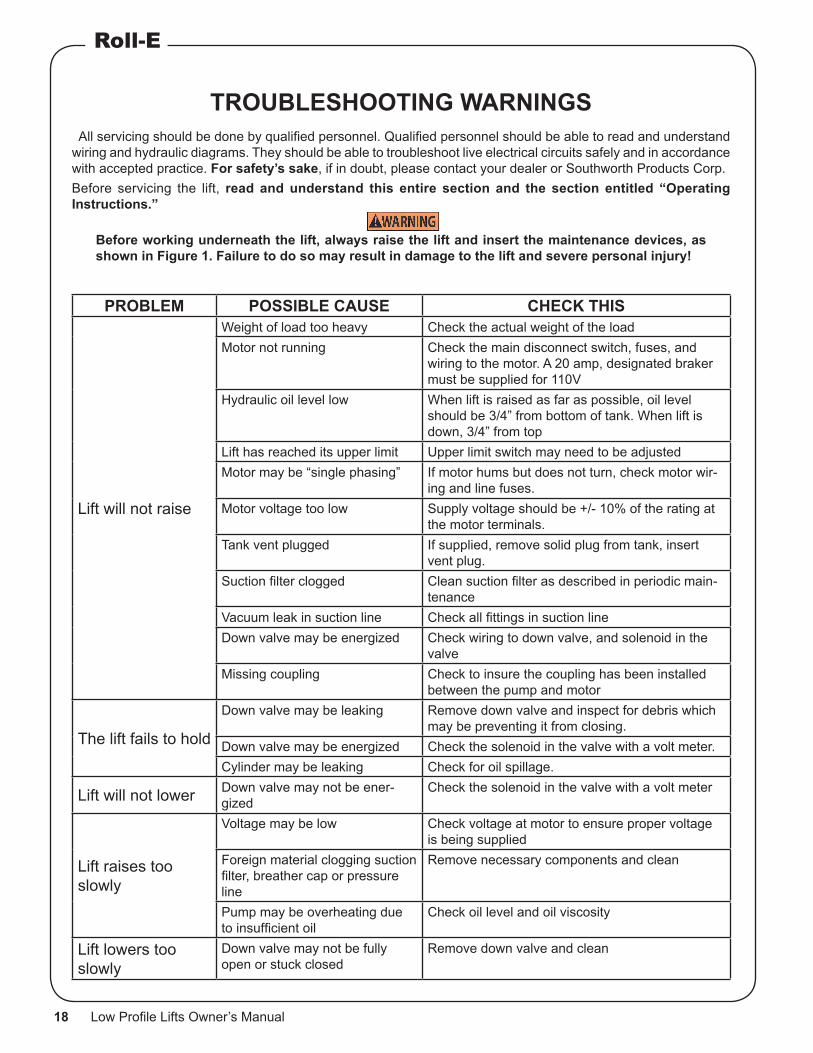
PROBLEM POSSIBLE CAUSE CHECK THIS
Lift will not raise
Weight of load too heavy Check the actual weight of the loadMotor not running Check the main disconnect switch, fuses, and
wiring to the motor. A 20 amp, designated braker must be supplied for 110V
Hydraulic oil level low When lift is raised as far as possible, oil level should be 3/4” from bottom of tank. When lift is down, 3/4” from top
Lift has reached its upper limit Upper limit switch may need to be adjustedMotor may be “single phasing” If motor hums but does not turn, check motor wir-
ing and line fuses.Motor voltage too low Supply voltage should be +/- 10% of the rating at
the motor terminals.Tank vent plugged If supplied, remove solid plug from tank, insert
vent plug.Suction filter clogged Clean suction filter as described in periodic main-
tenanceVacuum leak in suction line Check all fittings in suction lineDown valve may be energized Check wiring to down valve, and solenoid in the
valveMissing coupling Check to insure the coupling has been installed
between the pump and motor
The lift fails to hold
Down valve may be leaking Remove down valve and inspect for debris which may be preventing it from closing.
Down valve may be energized Check the solenoid in the valve with a volt meter.Cylinder may be leaking Check for oil spillage.
Lift will not lower Down valve may not be ener-gized
Check the solenoid in the valve with a volt meter
Lift raises too slowly
Voltage may be low Check voltage at motor to ensure proper voltage is being supplied
Foreign material clogging suction filter, breather cap or pressure line
Remove necessary components and clean
Pump may be overheating due to insufficient oil
Check oil level and oil viscosity
Lift lowers too slowly
Down valve may not be fully open or stuck closed
Remove down valve and clean
TROUBLESHOOTING WARNINGS All servicing should be done by qualified personnel. Qualified personnel should be able to read and understand wiring and hydraulic diagrams. They should be able to troubleshoot live electrical circuits safely and in accordance with accepted practice. For safety’s sake, if in doubt, please contact your dealer or Southworth Products Corp.Before servicing the lift, read and understand this entire section and the section entitled “Operating Instructions.”
WARNING!Before working underneath the lift, always raise the lift and insert the maintenance devices, as shown in Figure 1. Failure to do so may result in damage to the lift and severe personal injury!

SOUTHWORTH
Low Profile Lifts Owner’s Manual 19
Ordering Replacement PartsSouthworth has carefully chosen the components in your unit to be the best available for the purpose. Replacement parts should be identical to the original equipment. Southworth will not be responsible for equipment failures resulting from the use of incorrect replacement parts or from unauthorized modifications to the machine.
Southworth can supply all replacement parts for your Southworth lift. With your order, please include the model number and the serial number of the unit. You will find these numbers on the name plate.
To order replacement parts, please call the Parts Department at (207) 878-0700. Parts are shipped subject to the following terms:
• FOB factory.
• Returns only with the approval of our parts department.
• Payment net 30 days (except parts covered by warranty).
• Freight collect (except parts covered by warranty).
• The warranty for repair parts is 30 days from date of shipment.
Parts replaced under warranty are on a “charge-credit” basis. We will invoice you when we ship the replacement part, then credit you when you return the assumed substandard part, and we verify that it is covered by our warranty. Labor is not covered under warranty for Parts orders.
Parts DepartmentSouthworth Products Corp
P.O. Box 1380Portland, ME 04104-1380Telephone: (207) 878-0700
FAX: (207) [email protected]

Southworth Products Corp warrants this product to be free from defects in material or workmanship for a period of two (2) years of single shift usage from date of shipment, providing claim is made in writing within that time period. This warranty shall not cover modified designs for special applications, failure or defective operation caused by misuse, misapplication, negligence or accident, exceeding recommended capacities, failure to perform required maintenance or altering or repairing, unless alteration is authorized by Southworth Products Corp. Except as set forth herein, there are no other warranties, express or implied, including the warranties of merchantability and fitness for a particular purpose, all of which are hereby excluded.
Southworth Products Corp makes no warranty or representation with respect to the compliance of any product with state or local safety or product standard codes, and any failure to comply with such codes shall not be considered a de-fect of material or workmanship under this warranty. Southworth Products Corp shall not be liable for any direct or consequential damages arising out of such noncompliance.
Southworth Products Corp’s obligation under this warranty is limited to the re-placement or repair of defective components at its factory or another location at Southworth Products Corp’s discretion. The Southworth Warranty is for product sold with in North America. For products shipped outside of North America the warranty will be for replacement of defective parts only. Labor is not included. This is buyer’s sole remedy. Except as stated herein, Southworth Products Corp will not be liable for any loss, injury or damage to persons or property, nor for direct, indirect, or consequential damage of any kind, resulting from failure or defective operation of said product.
This warranty may be altered only in writing by Southworth Products Corp, Portland, Maine.
SOUTHWORTH PRODUCTS CORPP.O. Box 1380, Portland, ME 04104-1380Telephone: 800-743-1000 • 207-878-0700Fax: 207-797-4734www.SouthworthProducts.com
2 YEAR WARRANTY