Embed Size (px)
Citation preview

Owner's Manual
CRRI:TSMRW
SNOW THROWER1450 Series Briggs andPower-Propelled30" Two-Stage
Model No.917.881062
• EspaSol, p. 21
CAUTIO ."Read and follow all
Safety Rules and Instructionsbefore operating this equipment
Stratton Engine
Sears, Roebuck and Co., Hoffman Estates, IL 60179 U.S.A.Visit our Craftsman website: www.sears.com/craftsman

IMPORTANTSafe Operation Practices for Walk=Behind Snow Throwers
This snow thrower is capable of amputating hands and feet and throwing objects.Failure to observe the following safety instructions could result in serious injury.
& Look for this symbol to point out im-portant safety precautions. It meansCAUTION!!! BEOOMEALERT!!! YOURSAFETY IS INVOLVED.
&WARNING: Always disconnect sparkplug wire and place it where it cannotcontact plug in order to prevent acci-dental starting when setting up, trans-porting, adjusting or making repairs.
WARNING: This snow thrower is foruse on sidewalks, driveways and other
ground level surfaces. Caution shouldbe exercised while using on sloping sur-faces, Do not use snow thrower onsurfaces above ground level such asroofs of residences, garages, porchesor other such structures or buildings.
WARNING: Snow throwers have ex-posed rotating parts, which can cause
severe injury from contact, or from ma-terial thrown from the discharge chute.Keep the area of operation clear of allpersons, small children and pets at alltimes including startup.
CAUTION: Muffler and other engineparts become extremely hot duringoperation and remain hot after engine
has stopped. To avoid severe burns oncontact, stay away from these areas.
WARNING: Engine exhaust, some of
its constituents, and certain vehiclecomponents contain or emit chemi-cals known to the State of Californiato cause cancer and birth defects orother reproductive harm.
Training1. Read, understand and follow all instructions on the
machine and in the manual(s) before operating thisunit. Be thoroughly familiar with the controls and theproper use of the equipment. Know how to stop theunit and disengage the controls quickly.
2. Never allow children to operate the equipment. Neverallow adults to operate the equipment without properinstruction.
3. Keep the area of operation clear of all persons, par-ticularly small children.
4. Exercise caution to avoid slipping or falling, especiallywhen operating the snow thrower in reverse.
Preparation1. Thoroughly inspect the area where the equipment is
to be used and remove all doormats, sleds, boards,wires, and other foreign objects.
2. Disengage all clutches and shift into neutral beforestarting the engine (motor).
3. Do notoperatethe equipmentwithoutwearing adequatewinter garments. Avoid loose fitting clothing that canget caught in moving parts. Wear footwear that willimprove footing on slippery surfaces.
4. Handle fuel with care; it is highly flammable
(a) Use an approved fuel container.
(b) Never add fuel to a running engine or hot en-gine.
(c) Fill fuel tank outdoors with extreme care. Never fillfuel tank indoors.
(d) Never fill containers inside a vehicle or on a truckor trailer bed with a plastic liner. Always placecontainers on the ground, away from your vehicle,before filling.
(e) When practical, remove gas-powered equipmentfrom the truck or trailer and refuel it on the ground.If this is not possible, then refuel such equipmenton a trailer with a portable container, rather thanfrom a gasoline dispenser nozzle.
5,
6,
7.
(f) Keep the nozzle in contact with the rim of the fueltank or container opening at all times, until refuel-ing is complete. Do not use a nozzle lock-opendevice.
(g) Replace gasoline cap securely and wipe up spilledfuel.
(h) If fuel is spilled on clothing, change clothing im-mediately.
Use extension cords and receptacles as specified bythe manufacturer for all units with electric drive motorsor electric starting motors.
Adjust the collector housing height to clear gravel orcrushed rock surface.
Never attempt to make any adjustments while theengine (motor) is running (except when specificallyrecommended by manufacturer).
Always wear safety glasses or eye shields during op-eration or while performing an adjustment or repair toprotect eyes from foreign objects that may be thrownfrom the machine.
Operation1. Do not put hands or feet near or under rotating parts.
Keep clear of the discharge opening at all times.
2. Exercise extreme caution when operating on or cross-ing gravel drives, walks, or roads. Stay alert for hiddenhazards or traffic.
3. After striking a foreign object, stop the engine (motor),remove the wire from the spark plug, disconnect thecord on electric motors, thoroughly inspect the snowthrower for any damage, and repair the damage beforerestarting and operating the snow thrower.
4. If the unit should start to vibrate abnormally, stop theengine (motor) and check immediately for the cause.Vibration is generally a warning of trouble.
5. Stop the engine (motor) whenever you leave the oper-ating position, before unclogging the collector/impellerhousing or discharge chute, and when making anyrepairs, adjustments or inspections.

6. Whencleaning,repairingorinspectingthesnowthrower,stoptheengineandmakecertainthecollector/impel-lerand all movingpartshavestopped.Disconnectthesparkplugwireandkeepthewireawayfromtheplug.topreventsomeonefromaccidentallystartingtheengine.
7. Donotruntheengineindoors,exceptwhenstartingtheengineandfortransportingthesnowthrowerinoroutof thebuilding.Opentheoutsidedoors;exhaustfumesaredangerous.
8. Exerciseextremecautionwhenoperatingonslopes.9. Neveroperatethesnowthrowerwithoutproperguards,
andothersafetyprotectivedevicesinplaceandwork-ing.
10.Neverdirectthedischargetowardpeopleor areaswherepropertydamagecanoccur.Keepchildrenandothersaway.
11.Donotoverloadthemachinecapacitybyattemptingtoclearsnowattoofasta rate.
12.Neveroperatethemachineat hightransportspeedsonslipperysurfaces.Lookbehindandusecarewhenoperatingin reverse.
13.Disengagepowertothecollector/impellerwhensnowthroweris transportedornotinuse.
14.Useonlyattachmentsandaccessoriesapprovedbythemanufacturerofthesnowthrower(suchaswheelweights,counterweights,orcabs).
15.Neveroperatethesnowthrowerwithoutgoodvisibilityorlight.Alwaysbesureofyourfooting,andkeepafirmholdonthehandles.Walk;neverrun.
16.Nevertouchahotengineormuffler.
Clearing a Clogged Discharge ChuteHand contact with the rotating impeller inside the dischargechute is the most common cause of injury associated withsnow throwers. Never use your hand to clean out the dis-charge chute. To clear the chute:1. SHUTTHE ENGINE OFF!
2. Wait 10 seconds to be sure the impeller blades havestopped rotating.
3. Always use a clean-out tool, not your hands.
Maintenance and Storage1. Check shear bolts and other bolts at frequent intervals
for proper tightness to be sure the equipment is in safeworking condition.
2. Never store the machine with fuel in the fuel tankinside a building where ignition sources are presentsuch as hot water heaters, space heaters, or clothesdryers. Allow the engine to cool before storing in anyenclosure.
3. Always refer to operator's manual for important detailsif the snow thrower is to be stored for an extendedperiod.
4. Maintain or replace safety and instruction labels, asnecessary.
5. Run the machine a few minutes after throwing snowto prevent freeze-up of the collector/impeller.
TABLE OF CONTENTS
SAFETY RULES ........................................................ 2-3PRODUCT SPECIFICATIONS ...................................... 4CUSTOMER RESPONSiBiLITIES ................................ 4WARRANTY .................................................................. 4ASSEMBLY / PRE-OPERATION ............................... 6-8OPERATION ............................................................ 9=14
MAINTENANCE ..................................................... 15-16MAINTENANCE SCHEDULE ..................................... 15SERVICE AND ADJUSTMENTS ........................... 17=19STORAGE ................................................................... 19TROUBLESHOOTING ................................................ 20REPAIR PARTS ..................................................... 40-55SEARS SERVICE ................................... BACK COVER

UMITED2=YEARWARRANTY ON CRAFTSMAN SNOW THROWER
When used and maintained according to the operator's manual instructions, if this snow thrower fails due to adefect in material or workmanship within two years from the date of purchase, call 1-800-4-MY-HOME® to arrangefor free repair.During the first 30 days of purchase, there will be no charge to service the product in your home. For yourconvenience, in-home warranty service will still be available after the first 30 days of purchase, but a trip chargewill apply. This charge will be waived if you transport the product to an authorized Craftsman drop-off location, Forthe nearest authorized location, call 1-800-4-MY-HOME®,Warranty coverage does not include:• Expendable items that become worn during normal use, including but not limited to spark plugs, shear pins, belts,• Standard maintenance servicing, oil changes, or tune-ups.• Tire replacement or repair caused by punctures from outside objects, such as nails, thorns, stumps, or glass.• Repairs necessary because of operator abuse, including but not limited to damage caused by impacting objects
that bend the frame, crankshaft or auger, or over-speeding the engine.• Repairs necessary because of operator negligence, including but not limited to damage caused by improper
storage, failure to use the proper grade and amount of engine oil, or failure to maintain the equipment accordingto the instructions contained in the operator's manual
• Engine (fuel system) cleaning or repairs necessary because of fuel determined to be contaminated or oxidized(stale). In general, fuel should be used within 30 days of its purchase date.
• Normal deterioration and wear of the exterior finishes, or product label replacement,
This warranty applies for only 90 days if this product is used for commercial or rental purposes.
This warranty applies only while this product is within the United States.
This warranty gives you specific legal rights, and you may also have other rights, which vary, from state to state.
Seats, Roebuck And Co., Hoffman Estates, IL 60179
CONGRATULATIONS on your purchase of a new snowthrower. It has been designed, engineered and manufac-tured to give best possible dependability and performance.
Should you experience any problem you cannot eas-ily remedy, please contact your nearest Sears Parts &Repair Center. We have competent, well-trained tech-nicians and the proper tools to service or repair this unit.Please read and retain this manual. The instructionswill enable you to assemble and maintain your snowthrower properly. Always observe the "SAFETY RULES",
SERIAL NUMBER:
DATE OFPURCHASE:
THE MODELAND SERIAL NUMBERSWILL BE FOUNDON A DECALATTACH ED TOTHE REAR OFTHE SNOWTHROWER HOUSING.
YOUSHOULDRECORDBOTHSERIALNUMBERANDDATE OF PURCHASE AND KEEPIN A SAFE PLACEFOR FUTURE REFERENCE.
PRODUCT SPECiFiCATiONS
Gasoline Capacity 3.0 Quartsand Type: Unleaded Regular only
Oil Type SAE 5W-30 or 10W-30(API SG-SL): Synthetic SAE 5W-30
Oil Capacity: 18 Ounces
Spark Plug: Champion RJ19LMGap: 0,030"
CUSTOMER RESPONSIBiLITiES• Read and observe the safety rules.
• Follow a regular schedule in maintaining, caring forand using your snow thrower.
• Follow the instructions under "Maintenance" and "Stor-age" sections of this owner's manual.

PARTS PACKED SEPARATELY I CARTON
(1) POWERCORD
(1) FUEL STABiLiZER PACKET
START I
(2) SAFETY iGNiTiON KEYS
(1) MULTi=WRENCH
(1) DISCHARGE CHUTE
(1) AUGER CONTROL ROD
(1) TRACTION DRIVE CONTROL ROD _
EXTRA SHEAR BOLTS AND NUTS
(2) SHEAR BOLTS 1/4=20 x 1=3/4
©(2) SPACERS (2) LOCKNUTS
1/4=20
7
I
I
I
I
I
ROTATOR HEAD MOUNTING
(1) WASHER 3/8 (1) LOCKNUT 3/8
I
I
I
I
I
J
(3) RETAINERSPRINGS
CHUTE DEFLECTOR REMOTE CONTROL
(1) LOCKNUT5/16=18
(1) CARRIAGEBOLT 5/16=18 × 5/8
(1) LOCKNUT (1) NYLON1/4=20 WASHER
(1) SHOULDERBOLT 1/4=20 (1) SPRING

AS / RE-O ERATIONRead these instructions and this manual in its entiretybefore you attempt to assemble or operate your newsnow thrower. Reading the entire manual will familiar=ize you with the unit, which will assist you in assembly,operation and maintenance of the product.
Your new snow thrower has been assembled at the factorywith the exception of those parts left unassembled for ship-ping purposes. All parts such as nuts, washers, bolts, etc.,necessary to complete the assembly have been placed inthe parts bag. To ensure safe and proper operation of yoursnow thrower, all parts and hardware you assemble mustbe tightened securely. Use the correct tools as necessaryto ensure proper tightness.
REMOVE SNOW THROWER FROM CARTON
1. Remove all accessible loose parts and parts boxesfrom carton.
2. Cut down all four corners of carton and lay panels flat.
3. Remove the two (2) screws securing the auger housingto the pallet.
4. Remove all packing materials except plastic tie holdingspeed control rod to lower handle.
5. Remove the two (2) plastic ties securing upper handleto pallet.
6. Remove snow thrower from carton and check cartonthoroughly for additional loose parts.
HOW TO SET UP YOUR SNOW THROWER
TOOL BOX (See Fig. 10)
A toolbox is provided on your snow thrower. The toolbox islocated on top of the belt cover. Store the extra shear bolts,nuts and multi-wrench provided in parts bag in the toolbox.
NOTE: The multi-wrench may be used for assembly of thechute rotator head to snow thrower and making adjustmentsto the skid plates.
UNFOLD UPPER HANDLE
1. Raise upper handle to the operating position and tightenhandle knobs securely.
INSTALL SPEED CONTROL ROD (See Figs. 1 and 2)1. Remove plastic tie securing rod to lower handle.
2. Insert rod into speed control bracket and secure withretainer spring.
UPPERHANDLE
HANDLEKNOB
LOWERHANDLE
/' // ,/
i _ _ i
FIG. 1
SPEED CONTROL ROD
RETAINERSPRING
SPEED SPEEDCONTROL CONTROLBRACKET LEVER
FIG. 2

AS / RE-O ERATIONINSTALL TRACTION DRIVE CONTROL ROD
(See Figs. 3 and 4)
The traction drive control rod has the long loop on the endof the spring as shown.
1. Slide rubber sleeve up rod and hook end of spring intopivot bracket with loop opening down as shown.
2. With top end of rod positioned under left side of controlpanel, push rod down and insert top end of rod into holein drive control bracket. Secure with retainer spring.
INSTALL AUGER CONTROL ROD (See Figs. 5 and 6)
The auger control rod has the short loop on the end of thespring as shown.
1. Slide rubber sleeve up rod and hook end of spring intocontrol arm with loop opening up as shown.
2. With top end of rod positioned under right side ofcontrol panel, push down on rod and insert end of rodinto hole in auger control bracket. Secure with retainerspring.
FIG. 3
RETAINERSPRING
CONTROLBRACKET
FIG, 4
AUGER
ROD
RUBBERSLEEVE
CONTROLARM
FIG. 5
AUGER CONTROL ROD AUGERCONTROL
RETAINER LEVERSPRING \
CONTROLBRACKET
FIG. 6

AS BLY / RE..O ERATIONiNSTALL DISCHARGE CHUTE / CHUTE ROTATORHEAD (See Fig. 7)
NOTE: The multi-wrench provided in your parts bag maybe used to install the chute rotator head,
1, Place discharge chute assembly on top of chute basewith discharge opening toward front of snow thrower,
2, Position chute rotator head overchute bracket, Ifneces-sary, rotate chute assembly to align square and pin on un-derside of chute rotator head with holes inchute bracket,
3, With chute rotator head and chute bracket aligned,position chute rotator head on pin and threaded studof mounting bracket,
4, Install 3/8 washer and Iocknut on threaded stud andtighten securely,
PIN
STUD
CHUTEBRACKET
ROTATOR HEADCHUTE MOUNTINGROTATOR HEAD BRACKET
FiG. 7
iNSTALL CHUTE DEFLECTOR REMOTE CONTROL
(See Figs. 8 and 9)1, Install remote cable bracket to discharge chute with
5/16-18 carriage bolt and 5/16-18 Iocknut as shown,Tighten securely,
2, Install remote cable eyelet to chute deflector with1/4-20 shoulder bolt, nylon washer and 1/4-20 Iocknutas shown, Tighten securely,
3, Install spring hooks between hex nuts on chute rotatorhead and into hole in chute deflector as shown,
SPRING1/4-20 CHUTESHOULDER
HOOKNYLON BETWEENWASHER HEX HUTS
ON CHUTIE1/4-20 ROTATO RLOCKNUT
CABLEEYELET
5/16- ! 8CARRIAGE
BOLT
L _EMOTE
CABLERACKET
5/16-18LOCKNUT
FiG. 8
///
/
/
/'
CHUTE DEFLECTORCONTROL LEVER
I
FIG, 9
CHECK TiRE PRESSURE
The tires on you r snow th rower were overinflated at the fac-tory for shipping purposes. Correct and equal tire pressureis important for best snow throwing performance,
• Reduce tire pressure to 14-17 PSi (19-24,5 N-m),

OPERATIONKNOW YOUR SNOW THROWER
READ THIS OWNER'S MANUALAND ALL SAFETY RULES BEFORE OPERATING YOUR SNOWTHROWER. Comparethe illustrations with your snow thrower to familiarize yourself with the location of various controls and adjustments, Savethis manual for future reference,
These symbols may appear on your snow thrower or in literature supplied with the product. Learn and understandtheir meaning,
ENGINEOFF
I\1DANGER ENGINE FAST SLOW CHOKE PRIMER
OR WARNING ON
RFUEL OIL FORWARD REVERSE
READ AND FOLLOW ALL SAFETY INFORMATIONAND iNSTRUCTiONS BEFORE USE OF THIS PRODUCT.
KEEP THESE INSTRUCTIONS FOR FUTURE REFERENCE.
iGNITiON KEY.INSERT TO START
AND RUN,PULL OUT TO STOP.
DISENGAGED
ENGAGED
\ J
SNOWDISCHARGE
_J
TRACTIONDRIVECONTROL

OPERATIONGASOLINE ELECTRIC AUGER DISCHARGE CHUTE CONTROL LEVER
START BUTTON CONTROLLEVER DRIVE SPEED DEFLECTOR REMOTE
RECOIL X CONTROL LEVER CONTROL LEVER
\STARTERHANDLE
TRACTIONCHUTE DRIVE
CHOKE DEFLECTOR CONTROLCONTROL LEVER
SAFETYIGNITIONKEY ON / OFF
SWITCH
CHUTE
LH TURNTRIGGER
LIGHT
CLEAN-OUT TOOLKNOB
NOTE: ITEMS ABOVEARE SHOWN INTHEIR TYPICAL
LOCATION ON THEENGINE. ACTUAL
LOCATION MAY VARYWITH THE ENGINE
ON YOUR UNIT.
\
\\
TOOLBOX
DRIFT CUTTER
PLATE
AUGERS
FIG. 10
MEETS A,N,S,I, SAFETY REQUIREMENTSOur snow throwers conform to the standards of the American National Standards institute,
Toolbox - used to store spare shear bolts, Iocknuts andwrench,
Safety ignition key = must be inserted for the engine tostart and run, Remove when snow thrower is not in use,
Electric start button - used for starting the engine,
Recoil (auxiliary) starter handle-used for starting engine,
Primer - pumps additional fuel from the carburetor to thecylinder for use when starting a cold engine.
Choke Control - used for starting a cold engine.
ON / OFF switch = used to STOP the engine.
LH and RH turn triggers- used to steer the snow thrower.10
Drive speed control lever = used to select forward orreverse motion and speed of snow thrower,
Traction drive control lever- used to engage power-pro-pelled forward or reverse motion of snow thrower,
Auger control lever - used to engage auger motion(throw snow),
Discharge chute control lever - used to change thedirection the snow is thrown,
Deflector remote control lever - used to change thedistance the snow is thrown,
Skid plate - used to adjust height of scraper bar from ground,
Drift cutter - used to cut through deep snowdrifts,

OPERATIONThe operation of any snow thrower can resultin foreign objects thrown into the eyes, whichcan result insevere eye damage. Always wearsafety glasses or eye shields while operatingyour snow thrower or performing any adjust-
ments or repairs. We recommend standard safety glassesor a wide vision safety mask worn over spectacles.
HOW TO USE YOUR SNOW THROWER
Know how to operate all controls before adding fuel orattempting to start the engine.
STOPPING
TRACTION DRIVE
• Release traction drive control lever to stop the forwardor reverse movement of the snow thrower.
AUGER
• Release the auger control lever to stop throwing snow.ENGINE
1. Move ON / OFF switch to "OFF" position.
2. Remove (do not turn) safety ignition key to preventunauthorized use.
NOTE: Never use choke to stop engine.
TO USE CHOKE CONTROL (See Fig. 11)
The choke control is located on the engine. Use the chokecontrol whenever you are starting a cold engine. Do notuse to start a warm engine.
• To engage choke, turn knob counterclockwise. Slowlyturn knob clockwise to disengage.
FIG. 11
TO CONTROL SNOW DISCHARGE (See Fig, 12)
WARNING: Snow throwers have ex-posed rotating parts, which can cause
severe injury from contact, or from ma-terial thrown from the discharge chute.Keep the area of operation cJear of allpersons, small children and pets at alltimes including startup.
WARNING: if the discharge chute or
auger become clogged, shut-off engineand wait for all moving parts to stop, Usethe clean=out tool, NOT YOUR HANDS,to unclog the chute and/or auger.
The DIRECTION inwhich snow isto be thrown is controlledby the discharge chute control lever.
• Tochangethe discharge chute position, press downwardon discharge chute control lever and move lever leftor right until chute is in desired position. Be sure leversprings back and locks into desired position.
The DISTANCE that snow is thrown is controlled by theposition of the chute deflector. Set the deflector low tothrow snow a short distance; set the deflector higher tothrow snow farther.
Press downward on chute deflector control lever andmove lever forward to lower the deflector and decreasethe distance. Move lever back to raise the deflectorand increase the distance. Be sure lever springs backand locks into desired position.
DlSCHARGECHUTECONTROLLEVER
CHUTE DEFLECTORREMOTE CONTROLLEVER
FIG, 12
11

OPERATIONTO THROW SNOW (See Fig, 13)
The auger rotation is controlled by the auger control leverlocated on the right side handle.
• Squeeze auger control lever to handle to engage theauger and throw snow.
• Release the auger control lever to stop throwing snow.
TO MOVE FORWARD AND BACKWARD (See Fig. 15)SELF-PROPELLING, forward and reverse movement ofthe snow thrower, is controlled by the traction drive controllever located on the left side handle.
• Squeeze traction drive control lever to handle to engagethe drive system,
• Release traction drive control lever to stop the forwardor reverse movement of the snow thrower,
SPEED and DIRECTION are controlled by the drive speedcontrol lever.
FIG, 13
USING THE CLEAN-OUT TOOL (See Fig, 14)
In certain snow conditions, the discharge chute may be-come clogged with ice and snow, Use the clean-out toolto dislodge this blockage,
When cleaning, repairing, or inspecting, makecertain all controls are disengaged and the au-ger/impeller and all moving parts have stopped,Disconnect the spark plug wire and keep thewire away from the spark plug to prevent ac-cidental starting,
• Releasethe auger control lever and shut offthe engine.
• Removethe clean-out tool from it's mounting clip. Graspthe tool firmly by the handle and push and twist the toolinto the discharge chute to dislodge the blockage.
After the packed snow has been dislodged, return the clean-out tool to it's mounting clip by pushing it into the clip.
• Make sure the discharge chute is pointed in a safe di-rection (no vehicles, buildings, people, or other objectsare in the direction of discharge) before restarting theengine.
• Restart the engine, then squeeze the auger controllever to the handle to clear snow from the auger hous-ing and the discharge chute.
DISCHARGECHUTE
TOOL
MOUNTING I
• Press downward on the speed control lever and movelever to desired position BEFORE engaging the trac-tion drive control lever. Be sure lever springs back andlocks into desired position,
• Slower speeds are for heavier snow and faster speedsare for light snow and transporting the snow thrower. Itis recommended that you use a slower speed until youare familiar with the operation of the snow thrower.
NOTE: When both traction drive and auger control leversare engaged, the traction drive control lever will lock theauger control lever in the engaged position. This will allowyou to release your right hand from the handle and adjustthe discharge chute direction without interrupting the snowthrowing process,
TRACTION DRIVE //_CONTROLLEVER
FIG. 15
POWER STEERING OPERATION (See Fig, 16)
Steering triggers are used to assist in steering your snowthrower. The triggers are located on the underside of eachhandle. When atrigger is squeezed, it disengages the drivewheel on that side of snow thrower and allows it to turn inthat direction.
• To turn left- squeeze left side trigger,
• To turn right - squeeze right side trigger,
LH TURNTRIGGER
FIG, 14 12 FIG. 16

OPERATION
TO ADJUST SKiD PLATES (See Fig. 17)
NOTE: The wrench provided in your parts bag may beused to adjust the skid plates.
Skid plates are located on each side of the auger housingand adjust the clearance between the scraper bar and theground surface. Adjust skid plates evenly to proper heightfor current surface conditions. For removal of snow innormal conditions, such as a paved driveway or sidewalk,place skid plates in the highest position (lowest scraperclearance) to give a 5 mm clearance between the scraperbar and the ground. Use a middle position if the surfaceto be cleared is uneven.
NOTE: It is not recommended to operate the snow throwerover gravel or rocky surfaces. Objects such as gravel, rocksor other debris, can easily be picked up and thrown by theimpeller, which can cause serious personal injury, propertydamage or damage to the snow thrower.
• If snow thrower must be operated over gravel surface,use extra caution and be sure skid plates are adjustedto lowest (highest scraper clearance) position.
1. Shut off engine and wait for all moving parts to stop.
2. Adjust skid plates by loosening the hex nuts, then mov-ing skid plate to desired position. Be sure both platesare adjusted evenly. Tighten securely.
(LOW GROUND_)
AUGERHOUSING
SCRAPER BAR
I HEX_¢ NUTS PLATE
LOW POSITION (HIGH GROUND CLEARANCE)
FIG, 17
SCRAPER BAR
The scraper bar is not adjustable, but is reversible. Afterconsiderable use it may become worn. When it has wornalmost to the edge of the housing, it can be reversed,providing additional service before requiring replacement,Replace a damaged or worn scraper bar.
TO USE DRIFT CUTTERS (See Fig. 18)
Use the drift cutters to cut through deep snowdrifts that arehigher than the front of the snow thrower.
• Loosen upper adjustment nut enough to allow driftcutter to be raised to highest position and tighten nutsecurely. Repeat for opposite side of snow thrower.
• When not using drift cutters, loosen adjustment nut,lower to storage position and tighten nut securely.
AUGERHOUSING
STcORTIAoGE_ DRIFTCUTTER
ADJUSTMENT NUT
BEFORE STARTING THE ENGINE
CHECK ENGINE OiL LEVEL (See Fig. 19)
The engine on your snow thrower has been shipped, fromthe factory, already filled with oil.
1. Check engine oil with snow thrower on level ground.
2. Remove oil fill cap/dipstick and wipe clean, reinsertthe dipstick and screw tight, wait for a few seconds,remove and read oil level. If necessary, add oil until"FULL:.'mark on dipstick is reached. Do not overfill.
• To change engine oil, see "TO CHANGE ENGINE OIE'in the Maintenance section of this manual.
ADD GASOLINE (See Fig. 19)• Fill fuel tank to bottom of tank filler neck. Do not over-
fill. Use fresh, clean, regular unleaded gasoline witha minimum of 87 octane. Do not mix oil with gasoline.Purchase fuel in quantities that can be used within 30days to assure fuel freshness.
WARNING: Wipe off any spilled oil orfuel. Do not store, spill or use gasolinenear an open flame.
CAUTION: Alcohol blended fuels (called gas-ohol or using ethanol or methanol) can attractmoisture which leads to separation and for-mation of acids during storage. Acidic gas candamage the fuel system of an engine while instorage. To avoid engine problems, the fuelsystem should be emptied before storage of30 days or longer. Empty the gas tank, startthe engine and let it run until the fuel lines andcarburetor are empty. Use fresh fuel next sea-son. See Storage instructions for additionalinformation. Never use engine or carburetorcleaner products in the fuel tank or permanentdamage may occur.
CHOKE ENGINE OIL GASOLINECONTROL FILL CAP / DiPSTiCK FILLER CAP
STARTERBUTTON
PRIMER RECOILSTARTER
SAFETY HANDLE
IGNITION ON / OFFKEY SWITCH
NOTE: ALL ITEMS ARE SHOWN IN THEIR TYPICAL LOCATION.ACTUAL LOCATION MAY VARY WITH ENGINE ON YOUR UNIT.
FIG, 18 13 FIG, 19

OPERATIONTO START ENGINE 5. Pull recoil starter handle quickly. Do not allow starterYour snow thrower engine is equipped with both a 120 VoltA.C. electric starter and a recoil starter. The electric starteris equipped with a three-wire power cord and plug and isdesigned to operate on 120 Volt A.C. household current.
• Be sure your house is a 120 Volt A.C. three-wiregrounded system. If you are uncertain, consult alicensed electrician.
WARNING: Do not use the electric
starter if your house is not a 120 VoltA.C. three=wire grounded system. Se=rious personal injury or damage to yoursnow thrower could result.
COLD START- ELECTRIC STARTER
1. Insert safety ignition key (packed separately in partsbag) into ignition slot until it clicks. DO NOTtum the key.Keep the extra safety ignition key in a safe place.
2. Place ON / OFF switch in "ON" position.
3. Rotate choke control to "FULl" position.
4. Connect the power cord to the engine.
5. Plug the other end of the power cord into a three-holegrounded 120 Volt A.C. receptacle.
NOTE: Do not use primer when starting engine with theelectric starter.
6. Push starter button until engine starts.
IMPORTANT: Do not crank engine more than five con-tinuous seconds between each time you try to start. Wait5 to 10 seconds between each attempt.
7. When the engine starts, release the starter button andslowly move the choke control to the "OFF" position.
8. Disconnect the power cord from the receptacle first,then from the engine.
Allow the engine to warm up for a few minutes. Engine willnot develop full power until it has reached normal operat-ing temperature.
WARM START - ELECTRIC STARTER
Follow the steps above, keeping the choke control in the"OFF" position.COLD START - RECOIL STARTER
1. Insert safety ignition key (packed separately in partsbag) into ignition slot until it clicks. DO NOTturn the key.Keep the extra safety ignition key in a safe place.
2. Place ON / OFF switch in "ON" position.
3. Rotate choke control to "FULl" position.
4. Push the primer four (4) times if the temperature isbelow 15°F, or two (2) times if temperature is between15° and 50°R If temperature is above 50°F, priming isnot necessary.
NOTE: Over priming may cause flooding, preventing theengine from starting. If you do flood the engine, wait a fewminutes before attempting to start and DO NOT push theprimer.
6,
rope to snap back.
When the engine starts, release the recoil starter handleand slowly move the choke control to the "OFF" posi-tion.
Allow the engine to warm up for a few minutes. Engine willnot develop full power until it has reached normal operat-ing temperature.WARM START- RECOIL STARTER
Follow the steps above, keeping the choke in the "OFF"position. DO NOT push the primer.
BEFORE STOPPING
Run the engine for a few minutes to help dry off any mois-ture on the engine.
IF RECOIL STARTER HAS FROZEN
If the recoil starter has frozen and will not turn the engine,proceed as follows:
1. Grasp the recoil starter handle and slowly pull as muchrope out of the starter as possible.
2. Release the recoil starter handle and let it snap backagainst the starter.
If the engine still fails to start, repeat the above steps oruse the electric starter.
SNOW THROWING TiPS
• Go slower in deep, freezing or heavy wet snow. Usethe drive speed control, NOT the ON / OFF switch, toadjust speed.
• It is easier and more efficient to remove snow imme-diately after it falls.
• The best time to remove snow is the early morning. Atthis time the snow is usually dry and has not been ex-posed to the direct sun and warming temperatures.
• Slightly overlap each successive path to ensure allsnow will be removed.
Throw snow downwind whenever possible.
Adjust the skid plates to proper height for current snowconditions. See "TO ADJUST SKID PLATES" in thissection of this manual.
• For extremely heavy snow, reduce the width of snowremoval by overlapping previous path and movingslowly.
, Keep engine clean and clear of snow during use. Thiswill help air flow and extend engine life.
, After snow-throwing is completed, allow engine to run fora few minutes to melt snow and ice off the engine.
• Clean the entire snow thrower thoroughly after eachuse and wipe dry so it is ready for next use.
WARNING: Do not operate snowthrower if weather conditions impair vis-ibility, Throwing snow during a heavy,windy snowstorm can blind you and behazardous to the safe operation of thesnow thrower.
14

CE
HT Check for Loose Fasteners I_ I_
R Clean / Inspect Snow Thrower t1_ IfOW Check/Replace V-Belts I_
Lubrication Chart I_ If
Check Engine Oil LevelEN Change Engine Oil
Inspect Muffler
N Check / Replace Spark PlugE
Empty Fuel Tank
v't/
v'v'
GENERAL RECOMMENDATIONS
The warranty on this snow thrower does not cover itemsthat have been subjected to operator abuse or negligence.To receive full value from the warranty, operator mustmaintain snow thrower as instructed in this manual. Someadjustments will need to be made periodically to properlymaintain your snow thrower.
At least once a season, check to see if you should makeany of the adjustments described in the Service and Ad-justments section of this manual.
• At least once a year, you should replace the spark plugand check belts for wear. A new spark plug will helpyour engine run better and last longer.
• Follow the maintenance schedule in this manual.
NOTE: Use only Original Equipment Manufacturer (OEM)parts to service this unit. Failure to do so can cause the unitto malfunction and pose a risk of injury to the operator.
LUBRICATION CHART
(_ SAE 5W=30 Motor Oil
(_) See "ENGINE" inMaintenance section
(_) GeneralPurposeGrease
@ Engine oil
BEFORE EACH USE
1, Check engine oil level.2. Check for loose fasteners.
3, Check controls to be sure they are functioning properly.
LUBRICATION
Keep your snow thrower well lubricated(See "LUBRICATION CHART"), Auger
grease fittings
O Pivotpoints
SNOW THROWER
Always observe the safety rules when performing anymaintenance.
TIRES
• Maintain proper air pressure in both tires (14-17 RS.I./ 19-24.5 N-m).
Keep tires free of gasoline and oil, which can harmrubber.
NOTE: To seal tire punctures and prevent flat tires dueto slow leaks, tire sealant may be purchased from yourlocal parts dealer. Tire sealant also prevents tire dry rotand corrosion.
15

EV-BELTS TO CHANGE ENGINE OIL
Check V-belts for deterioration and wear after every 50hours of operation and replace if necessary. The beltsare not adjustable. Replace belts if they begin to slip fromwear. (See "TO REMOVE BELT COVER" in the Serviceand Adjustments section of this manual).
The V-belts on your snow thrower are of special constructionand should be replaced by original equipment manufacturer(OEM) belts available from your nearest dealer. Using otherthan OEM belts can cause personal injury or damage tothe snow thrower.
AUGER GEAR CASE
• The gear case was filled with lubricant to the properlevel at the factory. The only time the lubricant needsattention is if service has been performed on the gearcase.
• If lubricant is required, use only Ronex ED #1 grease.
TRACTION DRIVE SYSTEM
DO NOT lubricate the drive components inside the snowthrower. The sprockets, hex shafts, drive disc and frictionwheel require no lubrication. The bearings and bushingsare lifetime lubricated and require no maintenance.
CAUTION: Any lubricating of the above compo=nents can cause contamination of the frictionwheel and damage to the drive system of yoursnow thrower.
ENGINE
LUBRiCATiON
Use only high quality detergent oil rated with API serviceclassification SG-SL Select the oil's SAE viscosity gradeaccording to your expected operating temperature.
SAE VISCOSITY GRADES
°F -20 0 30 32 40
i°C -3'0 -20 =1'0 0
TEMPERATURE RANGE ANTICIPATEDBEFORE NEXT OiL CHANGE
10
NOTE: Although multi-viscosity oils (5W30, 10W30 etc.)improve starting in cold weather, these multi-viscosity oilswill result in increased oil consumption when used above32°F/0°C. Check your engine oil level more frequently toavoid possible engine damage from running low on oil.
Change the oil after every 25 hours of operation or at leastonce a year if the snow thrower is not used for 25 hoursin one year.
Check the crankcase oil level before starting the engine andafter each five (5) hours of continuous use. Tighten oil fillcap / dipstick securely each time you check the oil level.
Determine temperature range anticipated before next oilchange. All oil must meet API service classification SG-SL.• Be sure snow thrower is on level surface.
• Oil will drain more freely when warm.• Catch oil in a suitable container.
NOTE: The left side wheel may be removed from snowthrower for easier access to the oil drain plug and place-ment of a suitable container. The unit tilted, resting on theframe with the left wheel removed, will help drain any oiltrapped inside the engine. (See "TO REMOVE WHEELS"in the Service and Adjustments section of this manual).
1. Remove safety ignition key and disconnect spark plugwire from spark plug. Place wire where it cannot comein contact with plug.
2. Clean area around drain plug.
3. Remove drain plug and drain oil in a suitable container.
4. Install drain plug and tighten securely.
5. Wipe off any spilled oil from snow thrower and engine.
6. Install left wheel (if removed for draining oil). Be sure toinstall klick pin into proper hole in wheel axle (See "TOREMOVE WHEELS" in the Service and Adjustmentssection of this manual).
7. Remove oil fill cap/dipstick. Be careful not to allow dirtto enter the engine.
8. Refill engine with oil through oil dipstick tube. Pourslowly. Do not overfill. For approximate capacity see"PRODUCT SPECIFICATIONS"section of this manual.
9. Use gauge on oil fill cap/dipstick for checking level.Be sure dipstick cap is tightened securely for accuratereading. Keep oil at "FULL.' line on dipstick.
10. Wipe off any spilled oil.
MUFFLER
Inspect and replace corroded muffler as it could create afire hazard and/or damage.
SPARK PLUG
Replace spark plug at the beginning of each season or afterevery 100 hours of operation, which ever occurs first. Sparkplug type and gap setting are shown in the "PRODUCTSPECIFICATIONS" section of this manual.
CLEANING
iMPORTANT: For best performance, keep snow throwerhousing free of any dirt or trash, Clean the outside of yoursnow thrower after each use.
-- come in contact with plug,
Keep finished surfaces/wheels free of gasoline, oil, etc.
We do not recommend using a garden hose to cleanyour snow thrower unless the electrical system, mufflerand carburetor are covered to keep water out. Waterin engine can result in shortened engine life.
16

SERVICE ADJUSTMENTS
WARNING: To avoid serious injury, beforeperforming any service or adjustments:
1. Be sure the on/off switch is in theOFF position.
2, Remove safety ignition key.3. Make sure the augers and all movingparts have completely stopped.
4. Disconnect spark plug wire fromspark plug and place wire where itcannot come in contact with plug.
SNOW THROWER
TO ADJUST SNOW THROWER HEIGHT
See "TO ADJUST SKID PLATES" and "SCRAPER BAR"in the Operation section of this manual.
CHUTEDEFLECTOR
The chute deflector, attached to the top of the dischargechute, is provided to direct discharging snow away fromthe operator. If the deflector becomes damaged, it shouldbe replaced.
• Tochange direction and/or distance snow is discharged,see "TO CONTROL SNOW DISCHARGE" in the Op-eration section of this manual.
SHEAR BOLTS (See Fig. 20)AUGER SHEAR BOLTS
Both right and left-hand augers are secured to the augershaft with a shoulder/shear bolt and hex nut. Should a for-eign object or ice become lodged in the augers, the shearbolts are designed to break, preventing damage to anyother components. If one or both augers do not turn whenauger control lever is engaged, check to see if one or bothof the bolts have sheared. To replace the shear bolts:
1. Disengage all controls and move throttle control toSTOP position or move ON/OFF switch to OFF posi-tion. Wait for all moving parts to stop.
2. Remove safety ignition key and disconnect spark plugwire from spark plug. Place wire where it cannot comein contact with plug.
3. Align hole in auger hub with hole in auger shaft andinstall a new 1/4-20 x 2" shoulder/shear bolt. Install1/4-20 lock nut and tighten securely.
CAUTION: Do not substitute. Use only originalequipment shear bolts as supplied with yoursnow thrower.
4. Connect spark plug wire to spark plug. Replace safetyignition key.
IMPELLER SHEAR BOLTS
The impeller is secured to the impeller shaft with two (2)capscrew/shear bolts and hex nuts. Should a foreign objector ice become lodged in the impeller, the capscrews aredesigned to break, preventing damage to any other com-ponents. If impeller does not turn when auger control leveris engaged, check to see if the capscrews have sheared.To replace the capscrew/shear bolts:
1. Disengage all controls and move throttle control toSTOP position. Wait for all moving parts to stop.
2. Remove safety ignition key and disconnect spark plugwire from spark plug. Place wire where it cannot comein contact with plug.
3. Align holes in impeller hub with holes in impeller shaftand install two (2) new 1/4-20 x 1-5/8" capscrew/shearbolts. Install 1/4-20 Iocknuts and tighten securely.
i CAUTION: Do not substitute. Use only originalJ equipment capscrew/shear bolts as supplied |
with your snow thrower.
4. Connect spark plug wire to spark plug. Replace safetyignition key.
FIG, 20
TO REMOVE BELT COVER (See Fig. 21)1. Remove the two (2) screws securing belt cover to
frame.
2. Remove belt cover.
• Replace belt cover by installing cover and screws andtighten securely.
FIG, 2117

SERVICE ADJUSTMENTSTO REPLACE BELTS (See Fig. 22)
The auger and traction drive belts are not adjustable. If thebelts are damaged or begin to slip from wear, they shouldbe replaced. It is recommended that the belt(s) be replacedby a Sears service centre/department.
NOTE: It is recommended that both the auger and tractiondrive belt be replaced at the same time.
The V-belts on your snow thrower are of special constructionand should be replaced by original equipment manufacturer(OEM) belts available from your nearest Sears servicecentre/department. Using other than OEM belts can cause_ersonal injury or damage to the snow thrower.
WARNING: Belt replacement requiresseparation of the snow thrower, Whileseparating the auger housing from theframe assembly, it is important thatan assistant stand in the operatingposition and hold the snow throwerhandles, Serious personal injury and/ordamage to the unit could occur if thesnow thrower should fall during the beltchanging process.
FRAME AUGERASSEMBLY HOUSING
8. RELIEVE TENSION ON TRACTION DRIVE BELTIDLER and remove traction drive belt from aroundpulleys.
HINT: Insert a 3/8" drive ratchet (in the "ON" position) intothe square hole in idler arm and rotate ratchet clockwiseto relieve tension.
9. With tension relieved on idler, install new traction drivebelt around pulleys and inside belt keepers.
10. Install clutch rod in swing plate; secure with hairpin.
11. Place auger belt around and inside the groove of augerpulley only.
12. While your assistant slowly raises handles to rejointhe auger housing and frame assembly, pull up on theauger belt and squeeze sides together above pulleyso belt is fully seated in groove of pulley.
13. Bring snow thrower completely together and checkcarefully for proper routing of belts. If auger belt hasbecome dislodged from the pulley (by catching the idlerarm bracket while bringing snow thrower together),separate the snow thrower and repeat step 10. Beltmust be fully seated in pulley groove when bringingthe snow thrower together.
14. Install the two (2) hex bolts and tighten securely.
15. INSTALL ENGINE PULLEY- Place belt in pulley grooveand slide pulley on crankshaft. Install flat washer,Iockwasher and bolt and tighten securely (41-47 N-mtorque). Make sure belt is inside belt keeper.
16. INSTALL BELT COVER and two (2) screws. Tightensecurely.
17. INSTALL DISCHARGE CHUTE - See "INSTALL DIS-CHARGE CHUTE / CHUTE ROTATER HEAD" in theAssembly / Pre-Operation section of this manual.
1, REMOVE GASOLINE FROM FUEL TANK - Draingasoline from fuel tank into a suitable container, out-doors, away from fire or flame, Wipe up any spilledgasoline,
2, REMOVE DISCHARGE CHUTE - Loosen Iocknutsecuring chute rotator head to mounting bracket onlyenough to allow chute rotator head to be raised anddischarge chute to be removed from snow thrower,
3, REMOVE BELT COVER - See "TO REMOVE BELTCOVER" in this section of this manual,
4. REMOVE ENGINE PULLEY-Removebolt, lockwasherand flat washer securing pulley to engine crankshaft,Remove outside (auger) pulley only from crankshaft,
5, SEPARATE SNOW THROWER - With your assistantstanding in the operating position holding the handles,remove the two (2) bolts holding the auger housing andframe together,
I WARNING: As the last bolt is removed,m
&I have your assistant carefully lower the I
handles down to the ground.
6. REMOVE HAIRPIN FROM CLUTCH ROD and removeclutch rod from swing plate. Tip swing plate forward.
7. REMOVE AUGER BELT from around pulley.
18
HOLE
AUGERFRAME ROUSING
FIG. 22

TO REMOVE WHEELS (See Fig. 23)• Remove the klik pin and remove wheel from axle.
IMPORTANT: When installing wheel, be sure to use theaxle hole closest to the end of the shaft - do not use thehole in the wheel hub (if equipped), Inner hole in axle andhole in wheel hub are not used for your model snow thrower,
KLIK PIN (INSTALLIN OUTER HOLEOF AXLE ONLY)
OUTER HOLE
AXLE
WHEEL WHEEL HUB
FNG. 23
NOTE: To seal punctures or prevent flat tires due to slowleaks, tire sealant may be purchased from your local partsdealer, Tire sealant also prevents tire dry rot and corrosion,
ENGINE
CARBURETOR
Your carburetor is not adjustable. Engine performanceshould not be affected at altitudes up to 7,000 feet (2,134meters), If your engine does not operate properly due tosuspected carburetor problems, take your snow throwerto a Sears service centre/department,
ENGINE SPEED
Never tamper with the engine governor, which is factory setfor proper engine speed, Overspeeding the engine abovethe factory high speed setting can be dangerous and willvoid the warranty, If you think the engine-governed highspeed needs adjusting, contact a Sears Parts & RepairCenter, which has the proper equipment and experienceto make any necessary adjustments,
STO EImmediately prepare your snow thrower for storage atthe end of the season or if the unit will not be used for 30days or more,
WARNING: Never store the snowthrower with gasoline in the tank inside
a building where fumes may reach anopen flame, spark or pilot light as on afurnace, water heater, clothes dryer orgas appliance. Allow the engine to coolbefore storing in any enclosure.
SNOW THROWER
When snow thrower is to be stored for a period of time,clean it thoroughly, remove all dirt, grease, leaves, etc,Store in a clean, dry area.
1, Clean entire snow thrower (See "CLEANING" in theMaintenance section of this manual),
2, Inspect and replace belts, if necessary (See "TO RE-PLACE BELTS" in the Service and Adjustments sectionof this manual),
3, Lubricate as shown in the Maintenance section of thismanual,
4, Besurethat all nuts, bolts, screws, and pins are securelyfastened. Inspect moving parts for damage, breakageand wear, Replace if necessary,
5, Touch up all rusted or chipped paint surfaces; sandlightly before painting,
ENGINE
FUEL SYSTEM
IMPORTANT: It is important to prevent gum deposits fromforming in essential fuel system parts such as carburetor,fuel hose, or tank during storage, Alcohol blended fuels(called gasohol or using ethanol or methanol) can attractmoisture which leads to separation and formation of acidsduring storage. Acidic gas can damage the fuel system ofan engine while in storage,
19
• Empty the fuel tank by starting the engine and lettingit run until the fuel lines and carburetor are empty,
• Never use engine or carburetor cleaner products inthe fuel tank or permanent damage may occur,
• Use fresh fuel next season,
NOTE: Fuel stabilizer is an acceptable alternative in min-imizing the formation of fuel gum deposits during storage,Add stabilizer to gasoline in fuel tank or storage container.Always follow the mix ratio found on stabilizer container,Run engine at least 10 minutes after adding stabilizer toallow the stabilizer to reach the carburetor. Do not emptythe gas tank and carburetor if using fuel stabilizer,
ENGINE OIL
Drain oil (with engine warm) and replace with clean engineoil, (See "ENGINE" in the Maintenance section of thismanual),
3,
4,
CYLINDER
1, Remove spark plug,
2, Pour approximately one ounce (30 ml) of oil throughspark plug hole into cylinder,
Pull recoil starter handle slowly a few times to distributeoil,
Replace with new spark plug,
OTHER
• Remove safety ignition key; store it in a safe place,
• Do not store gasoline from one season to another,
• Replace your gasoline can if your can starts to rust.Rust and/or dirt in your gasoline will cause problems,
• If possible, store your snow thrower indoors and coverit to protect it from dust and dirt,
• Cover your snow thrower with a suitable protectivecover that does not retain moisture, Do not use plastic,Plastic cannot breathe, which allows condensation toform and will cause your snow thrower to rust,
IMPORTANT: Never cover snow thrower while engine/ex-haust area is still warm,

TROU OOTINGSee appropriate section in manual unless directed to a Sears service centre/department.
PROBLEM
Does not start
Loss of power
Engine idles orruns roughly
Excessivevibration
Recoil starter
is hard to pull
Loss of traction
drive / slowingof drive speed
Loss of snowdischarge orslowing ofsnow discharge
CAUSE
1. Fuel shut-off valve (if soequipped) in OFF position.
2. Safety ignition keyis not inserted.
3. Out of fuel.
4. Throttle in STOP position(or ON/OFF switch is OFF).
5. Choke in OFF position.6. Primer not depressed.7. Engine is flooded.8. Spark plug wire is
disconnected.
9. Bad spark plug.10. Stale fuel.11. Water in fuel.
1. Spark plug wire loose.2. Throwing too much snow.3. Fuel tank cap is covered
with ice or snow.
4. Dirty or clogged muffler.
1. Choke is in FULL position.2. Blockage in fuel line.3. Stale fuel.4. Water in fuel.5. Carburetor is in need of
adjustment or overhaul.
Loose parts or damagedaugers or impeller.
1. Frozen recoil starter.
1. Drive belt is worn.
2. Drive belt is off of pulley.3. Friction drive wheel is worn.
1. Auger belt is off of pulley.2. Auger belt is worn.3. Clogged discharge chute.4. Augers / impeller jammed.
CORRECTION
1. Turn fuel shut-off valve to OPEN position.
2. insert safety ignition key.
3. Fill fuel tank with fresh, clean gasoline.4. Move throttle to FAST position
(or ON/OFF switch to ON position).5. Move to FULL position.6. Prime as instructed in the Operation section of this manual.7. Wait a few minutes before restarting, DO NOT prime.8. Connect wire to spark plug.
9. Replace spark plug.10. Empty fuel tank & carburetor, refill with fresh, clean gasoline.11. Empty fuel tank & carburetor, refill with fresh, clean gasoline.
1. Reconnect spark plug wire.2. Reduce speed and width of swath.3. Remove ice and snow on and around fuel tank cap.
4. Clean or replace muffler.
1. Move choke to OFF position.2. Clean fuel line.
3. Empty fuel tank & carburetor, refill with fresh, clean gasoline.4. Empty fuel tank & carburetor, refill with fresh, clean gasoline.5. Contact a Sears service centre/department.
1. Tighten all fasteners. Replace damaged parts. If vibrationremains, contact a Sears service centre/department.
1. See "IF RECOIL STARTER HAS FROZEN"
in the Operation section of this manual.
1. Check / replace drive belt.2. Check / reinstall drive belt.3. Contact a Sears service centre/department.
1. Check / reinstall auger belt.2. Check / replace auger belt.3. Clean snow chute.
4. Remove debris or foreign object from augers / impeller.
20

IMPORTANTEProcedimientos de Funcionamiento Seguro Para IVl_quinas Quitanieves
Esta m&quina puede amputar manos y pies y lanzar objetos.El no observar las siguientes instrucciones de seguridad puede dar lugar a heridas graves.
Busque este simbolo que se=
_ala las ptecauciones de segu=tidad de jmportancia. Quiete decitiATENCION! iESTE ALERTO! SUSEGURIDAD ESTA COMPROMETIDA.
ADVERTENCIA: Siempte desconecte el
alambte de la bujia y pdngalo donde nopueda enttat en contacto con la bujJa,pata evitat el attanque pot accidente,dutante la ptepatacion, el ttansporte, elajuste o cuando se hacen tepataciones.
ADVERTENCIA: Esta maquina quita-nieves se puede utilizat en acetas,vias de acceso y ottas areas a nivel
del suelo. Hay que tenet ptecauci6nusandola sobte pendientes. No usat lamaquina quitanieves en areas sobte elnivel del suelo, como techos de casae,gatajes, p6tticos u ottas esttuctutas oedificioe similates.
ADVERTENCIA: Las maquinas quita-nieves tienen pattes gitatotias expues-tas, que pueden causat hetidas graves
pot contacto, o pot material lanzadodesde el conducto de eyecci6n. Man=tenet siempte el area de opetaci6n li=bte de toda persona, nitros peque5os yanimales domesticos, incluso dutantela puesta en matcha.
PRECAUCI6N: El silenciadot y ottaspiezas del motor Ilegan a ere exttema-damente calientes dutante la opetaci6ny siguen siendo calientes despues de
_'J_ que el motor haya patado. Pata evitatquemadutas sevetas, petmanezca lejosde estas areas.
ADVERTENCIA: El tubo de escape delmotor, algunos de sue constituyentes y
algunos componentes del vehiculo con=tienen o desprenden ptoductos quimi-cos conocidos en el Estado de Califot=nia como causa de cancer y defectos alnacimiento uottoedar_oe teptoductivoe.
Forrnaci6n
1. Antes de hacer funcionar esta unidad hay que leer, com-prender y seguir todas las instrucciones en al m&quinayen el manual(es). Familiarizarse completamente conlos mandos y el uso correcto de la m&quina. Hay quesaber como parar la unidad y desconectar los mandosr&pidamente.
2. No permitir nunca que menores de edad utilicen lamaquina. No permitir nunca que adultos sin adecuadainstrucci6n previa utilicen la maquina.
3. Mantener el &tea de operaci6n libre de toda persona,especialmente ni_os peque_os y animales domesti-OOS,
4. Atenci6n a evitar de resbalarse o caerse especialmentecuando se va marcha atr&s.
Preparaci6n1. Inspeccionar a fondo el &tea donde se va a utilizar la
maquina y quitar todos los felpudos, trineos, planchas,hilos y otros objeto ajenos.
2. Desconectartodoslos embragues en la posici6n neutraantes de poner en marcha el motor.
3. No accionar la m&quina sin Ilevar vestidos invernalesadecuados para el exterior. Evitar vestidos sueltos ycolgantes que puedan quedarse atrapados en las partesgiratorias. Calzar zapatos que mejoren la estabilidaden &teas resbaladizas.
4. Manejar el carburante con precauci6n; es altamenteinflamable.
(a) Usar un contenedor aprobado para carburante.
(b) No a_adir nunca carburante a un motor en mar-cha o caliente.
(c) Llenar el dep6sito de carburante al aire libre conextrema precauci6n. No Ilenar nunca el dep6sitode carburante al interior de un edificio.
(d) No Ilenar nunca contenedores dentro un vehiculoo en un cami6n o remolque revestido con forro depl&stico. Posicionar siempre los contenedores enel suelo, lejos de su vehiculo antes de Ilenarlos.
(e) Cuando sea pr&ctico, quitar los aparatos alimen-tados por gas del cami6n o del remolque y abas-tecer en el suelo. Si esto no fuera posible, enton-ces hay que abastecer tales aparatos sobre unremolque mediante contenedores port&tiles, m&sbien que con un inyector de distribuci6n de gaso-lina.
(f) Mantener siempre la boquilla en contacto con elborde de la apertura del dep6sito de carburante,hasta que el reaprovisionamiento este completo.No usar un dispositivo de cierre de la boquilla.
TABLA DE MATERIASREGLAS DE SECURIDAD .................................... 21=22ESPECIFICACIONES DEL PRODUCTO ................... 23GARANTIA ........................... ;, ..................................... 23MONTAJE / PRE=OPERACION ............................. 25=27OPERACION .......................................................... 28=34MANTENIMIENTO ................................................. 34-35 21
PROGAMA DE MANTENIMIENTO ............................ 34SERVICIO Y AJUSTES ......................................... 36=38ALMACENAMIENTO .................................................. 38IDENTIFICACION DE PROBLEMAS ......................... 39PARTES DE REPUESTO ...................................... 40=55SERVICIO SEARS ...................................... CONTRAPA

(g) Reponer el tap6n de carburante firmemente y se-car el carburante derramado.
(h) Si el carburante se derrama sobre vestidos, cam-biarlos inmediatamente.
5. Paratodas las unidades con motores de mando electricoo de encendido electrico, usar cables de prolongamientoy recept&culos especificados pot el fabricante.
6. Regular la altura de la m&quina quitanieves para evitar&teas de gravilla o de pedrisco.
7. No intentar nunca hacer regulaciones mientras el motoreste en marcha (excepto cuando est& recomendadoespecificamente por el fabricante).
8. Llevar siempre gafas de protecci6n o mascaras paralos ojos durante la utilizaci6n de la maquina o mientrasse haga una regulaci6n o una reparaci6n para protegerlos ojos de objetos extrafios que pueden set lanzadospot la m&quina quitanieves.
Funcionamiento
1. No meter las manos o los pies cerca o debajo de partesgiratorias. No acercarse nunca al &tea de apertura deeyecci6n.
2. Tener extremacautela mientras la m&quinafuncione enavenidas, caminos, carreteras de gravilla o los cruce.Estar alerta pot peligros escondidos o tr&fico.
3. Despues de golpear un objeto ajeno, parar el motor,quitar el cable de la bujia de encendido, desconectar elcable de los motores electricos, inspeccionar a fondola maquina quitanieves para detectar dafios y repara-rlos antes de volver a encender y utilizar la m&quinaquitanieves.
4. Si la unidad empezara a vibrar de manera anormal,parar el motor y controlar inmediatamente para detectarla causa. Las vibraciones son generalmente indicio deproblemas.
5. Parar el motor cada vez que se abandone la posici6nde funcionamiento, antes de limpiar el alojamientodel colector / impulsor o el conducto de eyecci6n ycuando se hagan reparaciones, regulaciones o inspec-ciones.
6, Cuando se limpie, repare o inspeccione la m&quina,cerciorarse de que todos los mandos esten desco-nectados y que la colector / impulsor y todas las partesm6viles esten paradas. Desconectar el cable de labujia de encendido y mantener el cable lejano de labujia de encendido para prevenir puestas en marchaaccidentales.
7. No hacer funcionar el motor al interior, excepto en lapuesta en marcha y para transportar la maquina quita-nieves dentro oafuera del edificio. Abrir las puertas qu edan al exterior; los gases de escape son peligrosos.
8. Tenet mucho cuidado cuando se trabaja en terrenospendientes.
9. Nunca hacer funcionar el quitanieves sin que sus pro-tecciones y los otros dispositivos de seguridad estenbien colocados y funcionen.
10. No dirigir nunca la eyecci6n hacia personas o &teasdonde se pueden producir dafios. No permitir que losnifios se acerquen.
11. No sobrecargar la capacidad de la maquina intentandodespejar nieve a una velocidad demasiado alta.
12. No conducir la m&quina demasiado r&pidamente sobresuperficies resbaladizas. Mirar atr&s y set prudentedurante la marcha atr&s.
13. Desconectar la alimentaci6n de la barrena / impulsorcuando se transporta o no se utiliza la m&quina quita-nieves.
14, Usar Onicamente accesorios aprobados pot el con-structor de la m&quina quitanieves (como pesos paralas ruedas, contrapesos o cabinas),
15, No hacer funcionar nunca la m&quina quitanieves sinuna buena visibilidad o iluminaci6n, Hay que estarsiempre seguros de los propios pasos y agarrarsefirmemente a la empufiadura, Caminar; nunca cor-rer,
16, Nunca tocar un motor o un silenciador de escapecalientes,
Limpiar un conducto de descarga obturadoEl contacto de la mano con el impulsor giratorio al interiordel conducto de descarga es la causa m&s comOn delesiones con las m&quinas quitanieve, Nunca usar lasmanos para limpiar el conducto de descarga, Para limpiarel conducto:
1. iAPAGAR EL MOTOR!
2. Esperar 10segundos para asegurarse de que las hojasdel impulsor hayan parado de girar.
3. Usar siempre una herramienta para limpiar, nunca lasmanos.
Mantenimiento y conservaci6n1. Controlar frecuentemente que el perno de cizalla y
los dem&s pernos esten adecuadamente apretadospara asegurar que la m&quina puede trabajar conseguridad.
2. No dejar nunca la m&quina quitanieves con carburanteen su dep6sito dentro de un edificio donde hayan fuen-tes de ignici6n, como agua caliente y calentadores deambiente o secadoras de ropa. Dejar enfriar el motorantes de guardar la m&quina al interior.
3. Hacer siempre referenciaalaguiade instrucciones deloperador para detallesimportantes si se ti ene que guar-dar la m&quina quitanieves pot un largo periodo.
4. Mantener o sustituir las etiquetas de seguridad e in-strucci6n, si fuera necesario.
5. Hacer funcionar la maquina quitanieves pot algunosminutos despues de lanzar nieve, para limpiar lamaquina y prevenir el congelamiento de la colector /impulsor.
22

GARANTIA LIMITADA DE 2 ANOS DEL LANZADOR DE NIEVE CRAFTSMAN
Siempre que se Io utiiice y se Io mantenga de acuerdo alas instrucciones deJ manual del usuario, si este lanzador denieve liega a faJlar debido a un defecto de los materiales o de fabricaci6n dentro de los dos aSos posteriores a la fecha decompra, Jlame aJ 1-800-4-MY-HOME® para gestionar su reparaci6n sin cargo.
Durante los primeros 30 dJas de dicho piazo, se le brindarA el servicio a domiciiio sin costo. Para su conveniencia,tambi6n podr_, disponer del servicio a domicilio despu6s de los primeros 30 dJas, pero se le cobrara un vi_.tico. El mismono ser_. apiicabJe si usted ileva la unidad a un centro autorizado de Craftsman. Para saber cuai le queda mas cerca, IlameaJ 1-800-4-MY-HOME®
La cobertura de la presente GarantJa no incluye:
• Aqueilos elementos perecederos que se desgastan por el uso habitual, incluidos, de manera no taxativa, las bujJas, lospernos del cortador y las correas.
• El servicio de mantenimiento est&ndar, los cambios de aceite o los afinados.
• El cambio o reparaci6n de neum_.ticos pinchados por objetos extra_os, tales como clavos, espinas, troncos o vidrios.
• Aqueilas reparaciones que deban hacerse por probiemas derivados de maJ uso por parte del operador, incluidos, demanera no taxativa, da_os causados por el impacto de objetos que tuerzan eJ bastidor, el eje del cigQeSai o la barrena,o bien por exigir demasiado al motor.
• Aquelias reparaciones que deban realizarse por problemas derivados de negligencia por parte del operador, incluidos,de manera no taxativa, los da_os que se produzcan por guardarlo en condiciones inapropiadas, el no utilizar aceite demotor del grado adecuado y en la cantidad correcta, o bien el no mantener el equipo de acuerdo alas instrucciones delmanual del usuario.
• Aquellas limpiezas o reparaciones que se le deban hacer al motor (sistema de combustible) toda vez que se determineque eJ combustible estaba contaminado u oxidado (en mai estado). En general, se debe utilizar eJ combustible dentrode los 30 dJas posteriores a su compra.
• El deterioro y desgaste normales de las terminaciones exteriores o el reemplazo de la etiqueta del equipo.
La presente garantJa sera valida por solo 90 dJas en caso que el equipo sea utilizado para fines comerciaies o de aiquiler.
La presente garantJa solo serA valida mientras el equipo permanezca dentro del territorio de los Estados Unidos.
La presente garantJa le otorga derechos legaies especJficos. Puede que usted tenga tambi6n otros derechos, los cuaiesvarJan de un estado a otro.
Sears, Roebuck and Co,, Hoffman Estates, IL 60179
FEUClTACIONES por la compra de su Mb_quina Quitanieves.Ha sido dise_ado, planificado y fabricado para darle la mejorconfiabilidad y el mejor rendimiento posible.
En el case de que se encuentre con cualquier problema queno pueda solucionar fa.cilmente, haga el favor de ponerse encontacto con un Centro de Piezas y Reparaci6n Sears o conun otro centro de servicio cualificado. Cuenta con t6cnicos
bien capacitados y competentes y con las herramientas adec-uadas para darle servicio o para reparar este unidad.
Haga el favor de leer y de guardar este manual. Estas instruc-clones le permitirb_n montar y mantener su unidad en formaadecuada. Siempre observe las "REGLAS DE SEGURIDAD."
NOMERODE SERIE:
FECHA DE COMPRA:
EL NOMERO DEL NODELO Y EL DE SERIE SEENCUENTRAN EN LA CALCOMANIA ADJUNTA A LAPARTE TRASERA DE LA CAJA DE LA M/_QUINA QUITA-NIEVES.
DEBE REGISTRAR TANTO EL NOMERO DE SERIECOME LA FECHA DE COMPRA Y MANTENGALOS ENUN LUGAR SEGURO PARA REFENCIA EN EL FUTURO.
ESPEClFICAClONES DEL PRODUCTO
Capacidad y 3.0 Cuartos
Tipo de Gasolina: Regular sin Plomo
Tipo de Aceite SAE 5W-30 o 10W-30
(API SG-SL): Sintetico SAE 5W-30
Capacidad de Aceite: 18 Onzas
BujJa: Champion RJ19LMAbertura: 0.030"
RESPONSABILIDADES DEL CMENTE• Lea y observe las reglas de seguridad.• Siga un programa regular de mantenimiento, cuidado y use
de su Maquina Quitanieves.• Siga las instrucciones descritas en las secciones "Manten-
imiento" y '_,lmacenamiento" de este Manual del Due_o.
23

PARTES EMPACADAS POR SEPARADO EL LA CAJA DE CARTON
(1) CABLE DEALIMENTACI()N
(1) PAQUETE DEESTABILIZADOR
DEL COMBUSIBLE
(1) MULTI=LLAVE
(2) LLAVESDE IGNICI6NDE SEGURIDAD
(1) CONDUCTO LA DESCARGA
(1) BIELA DE MANDO DE TALADRO
(1) BIELA DE MANDO DE TRACCI()N_
o
PERNOS Y TURCAS EXTRA PARA lLA C|ZAlLlLA
(2) PERNOS 1/4=20 x 2 (2) ESPACIADORS
©(2) TUERCAS DE
SEGURIDAD 1/4-20
1
I
I
SOPORTE DE CABEZA G|RATOR|A
(1) ARANDELA (1) TUERCA DE3/8 SEGURIDAD 3/8
I
I
I
I
I
]
I
I
I
(3) RESORTESDE RETENCK)N
MANDO A D|STANC|A DElL DEFLECTOR DElL CONDUCTO
(1) TUERCA (1) PERNO DEDE SEGURIDAD ACARREO5/16=18 5/16-18 x 5/8
(1) TUERCADE SEGURIDAD1/4=20
(1) ARANDELADE NIL()N
(1) PERNO DONRESALTO 1/4=20
(i)
24

f
MONTAJE / RE-O ERACILeer eetae inetruccionee y eete manual completamente antesde empezar a montar o hacer funcionar eu nuevo quitanievee.La lectura del manual le familiarizara con la unidad, Io cualle aeietira en el montaje, la operaci6n y el mantenimientodel producto.
Su nuevo quitanieves se ha montado en la fabrica excepto aquel-las partes que se han dejado sueltas por motivos de transporte.Todas las partes como las tuercas, arandelas, pernos, etc., nec-esarias para completar el ensamblaje se hallan en la bolsa delas partes. Para asegurar un funcionamiento seguro y adecuadode su quitanieves, todas estas partes que usted ensamblarb, hande apretarse muy bien. Usar las herramientas correctas queaseguren el apriete adecuado.
SACAR LA Mi_QUINA QUITANIEVESDEL CARTON
1. Sacar todas las partes sueltas y las cajas de partes delcart6n.
2. Cortar los cuatro b.ngulos del cart6n y apoyar los paneles enhorizontal.
3. Desmontar los dos (2) tornillos que sujetan el bastidor delbarrenas a la plataforma.
4. Quitar todos los materiales de empaquetamiento excepto ellazo de plb,stico que sujeta la biela del control de velocidad ala empu_adura inferior.
5. Desmontar los dos (2) lazos de pl_.stico que sujetan el em-pur_adura superior a la plataforma.
6. Sacar la maquina quitanieves del cart6n y controlar a fondoque no se hayan quedado en el cart6n partes adicionalessueltas.
BIELA DEMANDO
VELOCIDAD
"',"_, LAZO DEEMPU- i _ PLASTICO _'_'_'r,
POMO ELAEMPUNADURA ', ',
EMPUNADURA _ iINFERIOR ", ',
//
//
/ /
,/ ,/,/ /
COMO PREPARAR SUM.&QUINA QUITANIEVES
PORTAHERRAMIENTAS (Vet Fig. 10)Con su maquina quitanieves se le proporciona un portaherra-mientas. El portaherramientas est& situado sobre la cubierta dela correa. Guarde los pernos de cizalla de recambio, tuercas yIlave de tuercas en la bolsa de partes del portaherramientas.
NOTA: La Ilave de apriete se puede usar para montar la cabezagiratoria del conducto a la maquina quitanieves y para hacerregulaciones de las placas de deslizamiento.
DESPLEGAR LA EMPU_IADURA SUPERIOR
1. Alzar la empur_adura superior hasta la posici6n de operaci6ny apretar fuerte el pomo de la empur_adura.
MONTAR LA BIELADEL CONTROL DE VELOCIDAD (Vet Figs. 1 y 2)1. Quitar el lazo de pl_.stico que sujeta la biela a la empur_adura
inferior.
FIG. 1
BIELA DE MANDOLA VELOClDAD
RESORTE DERETENCION
DE LA VELOCIDAD
PALANCA DE MANDODE LA VELOClDAD
FIG. 2
2. Montar la biela en el soporte del control de velocidad y apretarcon el resorte de sujeci6n.
25

f
MONTAJE / RE-O ERACIONMONTAJE DE LA BIELADE MANDO DE LA TRACCI6N (Vet Figs. 3 y 4)La biela de mando de la tracci6n tiene un gancho largo en elextremo del resorte, como mostrado.
1. Deslizar el manguito de caucho sobre la biela y enganchar laterminaci6n del resorte en el soporte del pivote con el ganchoabierto hacia abajo como mostrado.
2. Con la extremidad superior de la biela colocada debajo dellado izquierdo del panel de control, empujar la biela haciaabajo e insertar el extremo de la biela en el orificio del soportedel control. Apretar con el resorte de sujeci6n.
MONTAR LA BIELADE MANDO DE LA BARRENA (Vet Figs. 5 y 6)La biela del mando de tracci6n tiene un gancho corto en la ex-tremidad del resorte, como mostrado.
1. Deslizar el manguito de caucho sobre la biela y engancharla terminaci6n del resorte al brazo de mando con el ganchoabierto hacia arriba como mostrado.
2. Con el extremo superior de la biela colocado debajo del ladoderecho de! panel de control, empujar la biela hacia abajoe insertar el extremo superior de la biela en el orificio en elsoporte de mando de la barrena. Apretar con el resorte desujeci6n.
BIELA DE MANDO•DE TRACClON
CAUCHO
BRAZO DEMANDO
BIELA DEMANDO DE
MANGUITO DECAUCHO
:2-°[; :'4
t; :: t; I
,z- {2 £;H
',%-'-i24_: ,-:_:)
FIG. 3
PALANCA DEMANDO DETRACClON
RESORTE DE
SOPORTEDE MANDODETRACClON
FIG. 4
FIG. 5
BIELA DE RESORTE PALANCAMANDO DERE- MANDODELA TENCION BARRENABARRENA
SOPORTEMANDO
BARRENA
FIG. 6
26

f
MONTAJE / RE-O ERACIMONTAR ELCONDUCTO DE EYECClON/CABEZAGIRATORIA DEL CONDUCTO (Ver Fig. 7)NOTA: la Ilave de apriete proporcionada en su bolsa de partes sepuede utilizar para instalar la cabeza giratoria del conducto.
1. Colocar el grupo del conducto de eyecci6n sobre la base delconducto con la abertura de eyecci6n hacia el frente de lam&quina quitanieves.
2. Posicionar la cabeza giratoriadel conducto sobre e! soporte delconducto. Si fuera necesado, girar el grupo del conducto paraalinear la escuadra y la clavija debajo de la cabeza giratoriadel conducto con los orificios en el soporte del conducto.
3. Con la cabeza giratoria del conducto y el soporte del conductoalineados, posicionar la cabeza giratoria del conducto sobrela clavija y el perno con filete del soporte de montaje.
4. Colocar una arandela y una contratuerca de 3/8 sobre el pernocon filete y apretar firmemente.
__CONT_A_
TUERCA3/SARANDELA
PASADORROSCADO
AL|NEE CABEZA GIRATORIADELCONDUCTO YSOPORTE ANTESDE APRETAR LACONTRA-TUERCA
SOPORTECABEZA GIRATORIA CABEZADEL CONDUCTO GIRATORIA
FIG. 7
SOPORTECONDUCTO
MONTAR EL MANDO A DISTANCIA DEL DEFLEC-TOR DEL CONDUCTO (Vet Figs. 8 y 9)1. Acoplar el soporte del cable remoto al conducto de eyecci6n
con un perno de madera de 5/16-18 y una contratuerca de5/16-18 como mostrado. Apretar firmemente.
2. Montar el ojal metbJico del cable remoto al deflector del con-ducto con un perno de collarin de 1/4-20, una arandela denylon, una arandela plana y una contratuerca de 1/4-20 comemostrado. Apretar firmemente.
3. Colocar resortes de gancho entre las tuercas hexagonales enla cabeza giratoria del conducto yen el orificio del deflectordel conducto, como mostrado.
1/4-20PERNO DECOLLARiN
ARANDELADE NYLON
1/4-20CONTRA-TUEROA
RESORTE DEFLECTORDEL
GANCHO ENTRETURCAS HE_
AGONALE$ ENCABEZA GI=
RATOR|A DELCONDUCTO
5/16-18PERNO DE
OJALDELCABLE
J
OPORTE
LOABLEREMOTO
5/16-18CONTRATUERCA
FIG. 8
PALANCA DE MANDODEL DEFLECTOR DE CONDUCTO
/
//
FIG. 9
CONTROLAR LA PRESION DE LOS NEUM.&TICOS
Los neumb, ticos de su m&quina quitanieves se han inflado m&sde Io normal por motivos de envio. Una correcta e igual presi6nde los neum&ticos es importante para la mejor prestaci6n en eldespeje de nieve.
Reducir la presi6n de neumaticos a 14-17 PSI (19-24.5 N-m).
27

f
O ERACIFAMILIARiCESE CON SU Mi_QUINA QUITANIEVESLEA ESTE MANUAL DEL DUEi_O Y LAS REGLAS DE SEGURIDAD ANTES DE OPERAR SU M,&,QUINA QUITANIEVES.
Compare las ilustraciones con su segadora para familiarizarse con la ubicaci6n de los diversos controles y ajustes. Guarde este manualpara referencia en el futuro.
Estos simbolos pueden apateser eobre su maquina quitanievee o en la literatura proporeionada con el producto. Aprenda ycomprenda sue eignificadoe.
PELIGRO o MOTOR LENTOATENCION ENCENDIDO
MOTOR RAPIDOAPAGADO
I\1ESTRANGULACION CEBADOR
RCOMBUSTIBLE ACEITE DALANTERO REVES
LEER Y SEGUIR TODAS LASINFORMACIONES DE SEGURIDAD
ANTES DE USAR ESTE PRODUCTO.GUARDAR ESTASINSTRUCCiONES
PARA CONSULTAS FUTURAS.
LLAVE DE|GN|CION.|NTRODUCiR PARA
PONER EN MARCHA,EXTRAER PARA APAGAR.
DESCARGADE LA NiEVE
DESEN=GANCHADO
ENGANCHADO
MANDO DELATRACCION
28

f
OPERACIMANGO DE PALANCA DE CONTROL DEL CONDUCTO DE EYECCION
DEPOSITO RETROCESO DE PALANCA PALANCA DEDE GASOLINA DE CONTROL DE LA PALANCA DE CONTROL DELSlLEN- MANGO DE CONTROL VELOCIDAD DE DEFLECTOR A DNSTANCJACJADOR RETROCESO DE LA GUiA PALANCA
DE BARRENA DECON- IRANQUE _ .CONTROLTROL DE LADE LA _ DEFLECTOR DE GUiA CONESTRA- DESCARGA TRACCJONNGU-LACION
CEBADOR
LLAVEDEENCENDIDO DE CONDUCTO DE jSEGURIDAD DESCARGA
INTERRUPTORDE ON/OFF
HERRAMIENTA
BARRENAS
NOTA:LAS PARTESMOSTRADAS ARRJBASEENCUENTRANENSU TiPJCA POSICleN
EN EL MOTOR. LAPOSlCION REAL
PUEDEVARJARDEPENDIENDO
DEL MOTOR ENSU UNIDAD.
\
GATILLODE
VU ELTA AiZQUIERDA
LUZ
MANILLA
SILENCIADOR
CORTADORDE
Palanca de control de la velocidad de guia - utilizada paraseleccionar la marcha adelante o arras y la velocidad de lamaquina quitanieves.
Interruptor de ON / OFF - utilizado para parar (STOP) elmotor.
Palanca de control de la guia con tracci6n - utilizada paraaccionar el movimiento propulsado de potencia adelante omarcha arras de la maquina quitanieves.
Palanca de control del conducto de eyecci6n - utilizadapara cambiar la direcci6n de lanzamiento de la nieve.
Palanca de control del deflector a distancia - utilizada pararegular la distancia a la que se lanza la nieve.
Placaa de deelizamiento - utilizada para regular la altura de labarra de arrastre del suelo.
Cortador de acumulacione8 - usado para cortar a traves deacumulaciones de nieve.
Palanca de control de la barrena - utilizada para conectar elmovimiento de la barrena (lanza nieve).
Portaherramientas - utilizada para guardar pernos varios ytuercas de recambio y Ilave de tuercas.
Gatilloa de vuelta a izquierda y derecha - utilizados paradirigir la maquioa quitanieves.
Mango de retroceso (auxiliar) de arranque - utilizado paraponer en marcha el motor.
Cebador - bombea mas carburante desde el carburador alcilindro para arranques con el motor frio.
Control de la estrangulacion - utilizado para arrancar conmotor frio.
Llave de encendido de eeguridad -tiene que introducirse paraque el motor arranque y funcione. Quitese cuando no se usa lamaquioa quitanieves.Bot6n de arranque electrico - utilizado para poner en marchael motor,
29
FIG. 11PLACAS DE
CUMPLE CON LOS REQUISITOS
DE SEGURIDAD DE LA A.N.S.I.
Nuestras m&quina quitanieves cumplen con los estandares
de seguridad del American National Standards Institute,

f
O ERACIONLa operaci6n de cualquier mb_quina quitanievespuede hacer que salten objetos extrafios dentrode sus ojos, Io que puede producir da_os gravesen estos. Siempre use anteojos de seguridado protecci6n para los ojos mientras opere sumb_quina quitanieves o cuando haga ajustes o
reparaciones. Recomendamos gafas o una mascara de se-guridad de visi6n amplia de seguridad usada sobre las gafas.
COMO UTILIZAR SU MAQUINA QUITANIEVES
Conozca eomo hacer funcionar todos los mandos antes de a_adir
carburante o intentar poner en marcha el motor.
PARARSEGU{A CONTRACCION
Soltar la palanca de control de guia a tracci6n para pararel movimiento hacia delante o marcha atrb, s de la maquinaquitanieves.
BARRENA
Soltar la palanca de control de la barrena para parar de lanzarnieve.
MOTOR
1. Poner el interruptor de ON / OFF en la posici6n de "OFF".
2. Quitar (sin girar) la Ilave de encendido de seguridad paraprevenir un uso no autorizado.
NOTA: No usar nunca el cebador para parar el motor.
USAR EL CONTROL DE LA ESTRANGULACION(Ver Fig. 11)El mando del cebador esta_ en el motor. Utilizar el mando del
cebador siempre que se arranque con motor frio. No utilizar paraponer en marcha un motor caliente.
Para conectar el cebador, girar el mando en el sentido inversode las agujas del reloj. Para desconectar, girar el mando pocoa poco en el sentido al de las agujas del reloj.
CERRADA'__ IXI ESTRANGULACION
FiG. 11
CONTROLAR LA EYECCION DE LA NIEVE
(Vet Fig. 12)
ADVERTENCIA: Lae maquinae quitanieveetienen partee giratoriae expuestae, que pu-
eden sauear heridae graves pot contacto,
o pot material lanzado deede el conductode eyecci6n, Mantener siempre el area deoperacion libre de toda persona, nihospequer_os y animalee dom_eticoe, inclueodurante la pueeta en marcha.
Si el conducto de descarga o la barrena ee ataeean,apagar el motor y eepera que lae partee en movimientoee hayan parado. Usar la herramienta de limpieza, NOLAS MANOS, para liberar el conducto y/o la barrena.
La DIRECCION en la que se lanza la nieve se controla mediantela palanca del mando del conducto de eyecci6n.
Para cambiar la posici6n del conducto de eyecci6n, empujarhacia abajo la palanca del mando del conducto de eyecclon ymover la palanca hacia la izquierda o la derecha hasta que elconducto este en la posici6n deseada. Cerciorarse de que lapalanca se suelte y se quede bloqueada en la posici6n deseada.
La DISTANCIA a la que se lanza la nieve se controla mediantela posici6n del deflector del conducto. Colocar el deflector bajopara lanzar nieve a breve distancia; colocarlo mb.s alto paralanzar la nieve mAs lejos.
Presionar hacia abajo la palanca de mando del deflector delconducto y mover la palanca hacia adelante para bajar eldeflector y disminuir la distancia. Mover la palanca del mandodel deflector del conducto hacia atr__s para alzar el deflectory aumentar la distancia. Asegurarse de que la palanca vayaatr&s y fijarla en la posici6n deseada.
PALANCA DE CONTROLDEL
PALANCA DE CONTROLDELDEFLECTOR A DISTANClA
FIG. 12
30

f
O ERACILANZAR LA NIEVE (Vet Fig. 13)La rotaci6n de la barrena se controla con la palanca de mandode la barrena posicionada en la empu_adura derecha.
Apretar la palanca de mando de la barrena hacia la empu_a-dura para conectar la barrena y lanzar nieve.
Soltar la palanca de mando de la barrena para parar de lanzarnieve.
PALANCADE
FIG. 13
USAR LA HERRAMIENTA PARA LIMPIAR
(Vet Fig. 14)En ciertas condiciones de la nieve, el conducto de descarga pu-ede atascarse con hielo y nieve. Usar la herramienta de limpiezapara quitar el bloqueo.
Cuando ae limpia, repara o ee inspecciona lamaquina, asegurarse de que todoa los mandos
est_n deaconectadoa y que la barrena/impul-sot y todaa las partes que se mueven est_nparados, Desconectar el cable de la clavija y
mantener el cable alejado de la bujia para evitaruna puesta en marcha accidental.
Soltar la palanca de mando de la barrena y apagar el motor.
Quitar la herramienta para limpiar de su clip de soporte.Agarrar la herramienta de modo firme per la empur_adura yempujar y girar la herramienta en el conducto de descargapara eliminar el atasco.
Despues de eliminar la nieve acumulada, volver a colocar laherramienta en su clip empujandolo en el clip.
Asegurarse de que el conducto de descarga este dirigido haciauna direcci6n segura (no vehiculos, edificios, personas u queotros objetos esten en la direcci6n de la descarga) antes deponer en marcha el motor.
Volver a poner en marcha el motor, luego oprimir la palancade mando de la barrena hacia la empu_adura para limpiar lanieve del alojamiento de la barrena y el conducto de descarga.
CONDUCTO DEDESCARGA
HERRAMIENTAPARA LIMPIAR
CLIP DE
MOVERSE ADELANTE Y ATR,_,S (Vet Fig. 15)
El movimiento AUTO-PROPULSADO, hacia adelante y marchaatrb, s de lamb, quina quitanieves, se controla mediante la palancade mando de la guia de tracci6n posicionada en la empur_aduraizquierda.
Apretar la palanca de mando de la guia de tracci6n hacia laempu_adura para conectar el sistema de guia.
Soltar la palanca de mando de la guia de tracci6n para pararel movimiento hacia delante o marcha atras de la maquinaquitanieves.
VELOClDAD y DIRECCION se controlan con la palanca delmando de velocidad de guia.
Mover la palanca del mando de la velocidad en la posici6ndeseada ANTES de conectar la palanca del mando de guiade tracci6n. Asegurarse de que la palanca vaya atras y fijarlaen la posici6n deseada.
ATENCION: No mover la palanca del mando dela velocidad cuando la palanca del mando dela guia de tracci6n esta conectada, Esto puedeperjudicar la maquina quitanieves.
Velocidades mb, s lentas son para nieve m&s pesada y ve-Iocidades mb,s altas para nieve ligera y para transportar lam&quina quitanieves. Se recomienda usar una velocidad masbaja hasta que se este acostumbrado alas operaciones dela maquina quitanieves.
NOTA: Cuando ambas palancas de mando de la guia de tracci6ny de la barrena esten conectadas, la palanca del mando de guiade tracci6n bloquearb, la palanca de mando de la barrena en laposici6n de conexi6n. Esto permitira soltar la mano derecha dela empu_adura y regular la direcci6n del conducto de eyecci6nsin interrumpir el proceso de lanzamiento de la nieve.
PALANCADE
CONTROLDELATRACCION
PALANCADECONTROLDELA
VELOCIDAD DE GUIA
FIG. 15
FUNCIONAMIENTO DE LA DIRECCK_N (Vet Fig. 16)Los activadores de direcci6n se utilizan para ayudar a dirigir sumaquina quitanieves. Los activadores estan posicionados en laparte inferior de cada empur_adura. Cuando se aprieta un activa-dor, se desconecta la rueda motriz de aquel lado de la m&quinaquitanieves y esto permite girar en esa direcci6n.
Para girar hacia la izquierda, apretar el activador del lado izq.
Para girar hacia la derecha, apretar el activador del lado dcha.
ACTIVADOR
FIG. 14 31 FIG. 16

f
O ERACIONREGULAR LAS PLACAS DE DESLIZAMIENTO
(Vet Fig. 17)NOTA: la Ilave de apriete proporcionada en su bolsa de partespuede utilizarse para regular las placas de deslizamiento.
Las placas de deslizamiente estAn posicionadas a cada ladodel alejamiente de la barrena y regulan la distancia entre labarra de arrastre y el suelo. Regule las placas de deslizamientouniformemente a la altura apropiada alas condiciones de lasuperficie. Para despejar nieve en condiciones normales, comoen vias de acceso adoquinadas o aceras, meter los placas dedeslizamiento en la posici6n mb,s alta (menor distancia de bar-rido) para dar una distancia de 1/8" entre la barra de arrastre yel suelo. Utilizar una posici6n intermedia si la superficie que sedebe despejar no es uniforme.
NOTA: No hacer funcionar la m__quina quitanieves sobre gravillao superficies rocesas. Objetos como gravilla, piedras u otrosescombros, pueden set facilmente recogidos y lanzados per elimpulsor, Io que puede causar heridas personales graves, dafiesa propiedades e a la mAquina quitanieves.
Si se tiene que utilizar la mAquina quitanieves sobre unasuperficie de gravilla, cerciorarse de que las placas de desl-izamiento esten reguladas en la posici6n mb.s baja (mayordistancia de barrido.
1. Apagar el motor y esperar a que todas las partes en movimientose hayan parado.
2. Regular los placas de deslizamiento destornillando tan lostuercas, seguidamente mover la placa de deslizamiento enla posici6n deseada. Asegurarse de que las dos placas est6nreguladas uniformemente. Apretar firmemente.
POSICl6N BASTIDOR(DISTANCIA DEL BARRE-BAJA DESDE NASEL SUELO)
_j BARRA DE
I
I
c_ _" DESLIZAMIENTOTUERCAS
/POSICI6N BAJA (DISTANCIA ALTA DESDE EL SUELO)
FIG. 17
BARRA DE ARRASTRE
La barra de arrastre no se puede regular, pero es reversible.Despu6s de un uso muy prolongado, puede desgastarse. Cuandose haya consumido casi hasta el borde del alojamiento, se puedeusar por el otro lade, pudi6ndola utilizar por mb,s tiempo antes deque sea necesario un recambio. Sustituir una barra de arrastreda_ada o desgastada.
USAR LOS CORTADORES DE ACUMULACIONES(Vet Fig. 18)Usar los cortadores de acumulaciones para cortar a trav6s deacumulaciones de nieve que son mAs altas que la parte frontaldel quitanieves.
Aflojar latuerca de ajuste superior para permitir que el cortadorde acumulaciones suba hasta la posici6n mAs alta y apretarfirmemente. Repetir para el lado opuesto del quitanieves.
Cuando no se usan los cortadores de acumulaciones, aflojarla tuerca de ajuste, bajar hasta la posici6n de almacenaje yapretar la tuerca de mode seguro.
BASTIDOR DELBARRENAS
POSICI6N DEALMACENAJE CORTADOREDE
ACUMULACIONES
/ TUEROA\ DEAJUSTE
FIG. 18
ANTES DE PONER EN MARCHA EL MOTOR
CONTROLAR EL NIVEL DE ACEITE DEL MOTOR(Ver Fig. 19)El motor de su m_tquina quitanieves viene de la fb.brica ya Ilenode aceite.
1. Controlar el aceite del motor con la maquina quitanieves sobreun terreno llano.
2. Sacar el tap6n /varilla de nivel del relleno de aceite y limpiarla,volver a poner la varilla y enroscar el tap6n firmemente, esperaralgunos segundos, sacar la varilla y leer el nivel de aceite. Sifuera necesario, a_adir aceite hasta Ilegar a la marca "FULl"(lleno) en la varilla. No Ilenar demasiado.
Para cambiar el aceite del motor, ver "COMO CAMBIAR ELACEITE DEL MOTOR" en la secci6n de Mantenimiento deeste manual.
32
TRANGU- DE NIVELLACION
\
DOR
LLAVE DEENCENDIDO DESEGURIDAD
CONTROL TAPA DEL DEPOSITO DE AOEITE DEL TAPA DELDE LA ES= MOTOR CON VARILLAINDICADORA DEPOSITO
DE
BOT6N DE
ARRAN-Q UE
- ELEC-
MANGODE RETRO-
CESO (AUX-ILIAR) DE
ARRANQUE
INTERRUPTOR DE ON/OFFNOTA" TODAS LASPARTES SE MUESTRAN EN SU pOSICl6N TiPICA. LA POSICl6NREAL PUEDE CAMBIAR SEGUN EL MOTOR DE SU UNIDAD.
FIG. 19
AGREGUE GASOLINA (Ver Fig. 19)Llene el estanque de combustible hasta la parte inferiordel cuello de relleno del estanque de gasolina. No Io Ilenedemasiado. Use gasolina regular, sin plomo, nueva y limpiacon el minimo de 87 octanos. No mezcle el aceite con la
gasolina. Para asegurar que la gasolina utilizada sea frescacompre estanques los cuales puedan ser utilizados durantelos primeros 30 dias.

f
0 ERACIPUESTA EN MARCHA DEL MOTOR 5. Tirarlaempuffaduradelarrancadorderetrocesorb.pidamente.
El motor de su maquina quitanieves esta equipado tanto con unarrancador electrico de 120 Voltios A.C. como con un arrancador
de retroceso. El arrancador el6ctrico estb, equipado con un cablede potencia de tres hilos y un enchufe y ester proyectado paraque funcione con corriente domestica de 120 Voltios A.C.
AsegQrese que la instalaci6n electrica de su casa sea unsistema de tres hilos puesta a tierra de 120 Voltios A.C. Sino estb. seguro, consulte un electricista autorizado.
ADVERTENCIA: No use el arrancadorel6ctrico si la instalaei6n eleetrica desu casa no es un sisterna de tree hilospuesta a tierra de 120 Voltios A.C. Po-drian resuitar heridas personal graveso dar_os a su rnaquina quitanieves.
PUESTA EN MARCH,A CON EL MOTOR FRiO- ARRANCADOR ELECTRICO
1. Insertar la Ilave de encendido de seguridad (embalado sepa-rado en bolso de las piezas) en la posici6n de encendido hastaque haga un ruido seco. NO girar la Ilave. Guardar la Ilave deencendido de seguridad de recambio en un lugar seguro.
2. Poner el interruptor de ON / OFF en la posici6n de "ON".
3. Girar el mando del obturador en la posici6n FULL.
4. Conectar el cable de potencia al motor.
5. Enchufar la otra extremidad del cable de potencia en un en-chufe de tres hilos con puesta a tierra de 120 Voltios A.C.
NOTA: No usar el cebador cuando se pone en marcha el motorcon el arranque electrico.
6. Pulsar el bot6n de arranque hasta que el motor se enci-ende.
IMPORTANTE: No hacer girar e! motor por m_ts de 5 segundoscontinuativamente cada vez que intente poner en marcha el mo-tor. Esperar de 5 a 10 segundos entre cada tentativa.
7. Cuando el motor se pone en marcha, soltar el bot6n de ar-ranque y mover lentamente el mando del obturador hasta laposlclon OFR
8. Desconectar el cable de potencia antes del enchufe y despu6sdel motor.
Dejar que el motor se caliente por algunos minutos. El motor noproporcionara la plena potencia hasta que no haya alcanzadola temperatura normal de funcionamiento.
PUESTA EN MARCHA CON EL MOTOR CALIENTE -ARRANCADOR ELECTRICO
Seguir los pasos descritos arriba, manteniendo el mando delobturador en la posici6n OFR
PUESTA EN MARCHA CON EL MOTOR FRiO -ARRANCADOR DE RETROCESO
1. Insertar la Ilave de encendido de seguridad (embalado sepa-rado en bolso de las piezas) en la posici6n de encendido hastaque haga un ruido seco. NO girar la Ilave. Guardar la Ilave deencendido de seguridad de recambio en un lugar seguro.
2. Poner el interruptor de ON / OFF en la posici6n de "ON".
3. Girar el mando del obturador en la posici6n FULL.
4. Pulsar el cebador cuatro (4) veces si la temperatura esta pordebajo de los 15°F, o dos (2) veces si la temperatura estb,entre los 15 ° y los 50°R Si la temperatura esta por encimade los 50°F, el cebador no es necesario.
NOTA: Utilizar demasiado el cebador puede ahogar el motor,impidiendo el arranque. En caso de que se ahogue e! motor,esperar algunos minutos antes de intentar poner en marcha yNO pulsar el cebador.
No soltar de golpe la cuerda del arrancador.
6. Cuando el motor arranca, soltar la empufiadura del arranca-dor de retroceso y mover lentamente el mando del obturadorhasta la posici6n OFE
Dejar que el motor se caliente por algunos minutos. El motor noproporcionarb, la plena potencia hasta que no haya alcanzadola temperatura normal de funcionamiento.
PUESTA EN MARCHA CON EL MOTOR CALIENTE -ARRANCADOR DE RETROCESO
Seguir los pasos descritos arriba, manteniendo el mando delobturador en la posici6n OFE NO pulsar el cebador.
ANTES DEPARAR
Hacer funcionar el motor por algunos minutos para ayudar asecar toda humedad del motor.
SI EL ARRANCADOR DE RETROCESO SE HA CONGE-LADO
Si el arrancador de retroceso se ha congelado y no pone enmarcha el motor, hacer Io siguiente:
1. Coger la empu_adura del arrancador de retroceso ytirar lenta-mente cuanta mas cuerda sea posible fuera del arrancador.
2. Soltar la empu_adura del arrancador de retroceso y dejarlair contra el arrancador.
Si aun asi el motor no arranca, repetir los pasos descritos arribao utilizar el arrancador electrico.
33
CONSEJOS PARA LANZAR LA NIEVEIr mas lentamente en nieve alta, helada o fuertemente mojada.Para regular lavelocidad con respecto al suelo, utilizar el mandode velocidad de guia, y NO el interruptor de ON/OFE
Es mb_s f&cil y eficiente despejar la nieve inmediatamentedespu6s de que haya caido.
El mejor momento para despejar la nieve es temprano por lamafiana. En este momento la nieve estb, normalmente seca
y no ha sido expuesta directamente al sol y a temperaturascalientes.
Hacer coincidir cada camino sucesivo para asegurar el despejede toda la nieve.
Lanzar la nieve sotavento siempre que sea posible.
Regular las placas de deslizamiento a la altura adecuada alas actuales condiciones de la nieve. Ver "PARA REGULARLAS PLACAS DE DESLIZAMIENTO" en esta secci6n delmanual.
Para nieve considerablemente pesada, reducir la anchuradel despeje de nieve sobreponiendo los caminos previos yandando lentamente.
• Mantener el motor limpio y libre de nieve durante el uso. Estoayudarb, a hacer pasar aire y prolongar_, la vida del motor.
Despu6s de completar el trabajo de despejar nieve, dejar queel motor gire por algunos minutos para derretir nieve y hieloque puedan estar en el motor.
Limpiar a fondo toda la m&quina quitanieves despu6s de cadauso y secarla para que este lista para el pr6ximo uso.
ADVERTENCIA: No hacer funcionar larnaquina quitanJeves si Jas condiciones
del tiempo deterioran la visibilidad.Despejar nieve durante una fuertey ventosa tormenta de nieve puedeofuscarles y ser peligroso para unfuncionarniento seguro de la rnaquinaquitanieves.

lENTO
M Revisar si hay Sujetadores Sueltos
Limpiar / Inspeccionar el mAquina quitanieves
i1_ Cambiar / Revisar las Correas
N Lubricaci6n
rRevisar el nivel del Aceite
M Cambiar el Aceite del motor
Inspeccionar el Silenciador
Cambiar / Revisar la Buj{a
Vaciar el Dep6sito del Combustible
t/ t/t/ v'
t/t/ i/
i/t/
t/i/
mmmmm m mmm
TABLA DE LUBRICACION
RECOMENDAClONES GENERALESLa garantia de esta maquina quitanieves no cubre los articulosque han estado sujetos al abuso o a la negligencia del operador.Para recibir todo el valor de la garantia, el operador tiene quemantener la maquina quitanieves segOn las instrucciones descritasen este manual. Hay algunos ajustes que se tienen que haceren forma peri6dica para poder mantener su maquina quitanievesadecuadamente. AI menos una vez cada estaci6n comprobar sies necesario efectuar los ajustes descritos en las secciones deServicio y Ajustes de este manual.
Una vez al a_o, cambie la bujia, limpie o cambie el elementodel filtro de aire y revise si la cuchilla esta desgastada. Unabujia nueva y un elemento del filtro de aire limpio/nuevoaseguran la mezcla de aire-combustible adecuada y ayudana que su motor funcione mejor y que dure m&s.Siga el programa de mantenimiento en este manual.
NOTA: Usar solo parte originales del equipo del fabricante(OEM) para realizar el mantenimiento de esta unidad. No haceresto puede causar el funcionamiento incorrecto de la unidad yarriesgar la salud del operador.
ANTES DE CADA USO1. Revise el nivel del aceite del motor.
2. Revise si hay sujetadores sueltos.
3. Controlar los mando para asegurarse de que funcionen ad-ecuadamente.
LUBRICAClON
Mantenga el maquina quitanieves bien lubricada(ver la "TABLA DE LUBRICACION').
(_) SAE 5W-30Aceite del Motor
(_) Vea "MOTOR"en la seccion de
Mantenirniento
(_ Grasa ParaUso General
Aceite delMotor
(_ CasquilloGrasa Barrena
PuntosPivote
34

MAQUINA QUITANIEVESSiempre observe las reglas de seguridad cuando haga el man-tenimiento.
LLANTASMantener la presi6n adecuada en ambos neumAticos (14-17RS.I./19-24.5 N-m).
• Mantenga las Ilantas sin gasolina o aceite, que pueden dafiarla goma.
NOTA: Para sellar los neumAticos y prevenir neumAticos desin-flados a causa de p@didas ligeras, se puede comprar sellador alefecto en el revendedor de partes local. EI sellador para neumAticostambien previene grietas y corrosi6n del neumatico.
CORREAS EN VControJar el deterioro y el desgaste de las correas en V despu6sde 50 horas de funcionamiento y sustituir si fuera necesario. Lascorreas no se pueden regular. Sustituir las correas si empiezan aresbalar debido al desgaste. (Ver" QUITAR EL CU BRE CORREAS"en la secci6n Mantenimiento y Regulaciones de este manual).
Las correas en V de su quitanieve tienen u na con strucci6n especialy han de ser sustituidos con correas originales (OEM) disponiblesen su revendedor mas cercano. Usar otras correas no originalespuede causar heridas personales o dafiar el quitanieve.
CAJA DE ENGRANAJES DE LA BARRENA• La caja de engranajes fue Ilenada en la fabrica con lubricante
hasta el nivel. Se tiene que prestar atenci6n al lubricante s61o sise ha efectuado un mantenimiento a la caja de engranajes.
• Si se requiere lubricante, usar s61o grasa Ronex ED #1.
SISTEMA DE TRACCION
NO lubricar las partes de guia dentro de la mAquina quitanieves.Las coronas dentadas, los Arboles hexagonales, el disco de guiay la rueda de fricci6n no necesitan lubricaci6n. Los rodamientos ycojinetes estAn lubricados a per vida y no necesitan mantenimiento.
ATENCION: Toda lubricaci6n de las partesdescritas arriba puede causar contarninaci6nde la rueda de fricci6n y dar_ar el sistema deguia de su rnaquina quitanieves.
MOTORLUBRICACI6N
Use solamente aceite de detergente de alta calidad clasificado conla clasificaci6n SG-SL de servicio API. Seleccione la calidad de
viscosidad SAE segOn su temperatura de operaci6n esperada.
CALIDADES DE VlSCOSIDAD DE SAE
,°F -20 0 30 32 40
°c -3'0 -2'o -?0 bGAMA DE TEMPERATURA ANTICIPADA
ANTES DEL PROXIMO CAMBIO DE ACEITE
10
AVlSO: A pesar de que los aceites de multiviscosidad (5W30,10W30, etc.) mejoran el arranque en clima frio, estos aceites demultiviscosidad van ha aumentar el consumo de aceite cuando
se usan en temperaturas sobre 32 ° R Revise el nivel del aceitedeJ motor mAs a menudo, para evitar un posible dafio en el motor,debido a que no tiene suficiente aceite. Cambie el aceite despu6sde 25 horas de operaci6n o por Io menos una vez al afio si lamaquina quitanieves se utiliza menos 25 horas el afio. Reviseel nivel del aceite del cArter antes de arrancar el motor y despuesde cada cinco (5) horas de uso continuado. Apriete el tap6n delaceite en forma segura cada vez que revise el nivel del aceite. 35
PARA CAMBIAR EL ACEITE DEL MOTOR
Determinar la temperatura anticipada antes de cambiar el aceite.Todo el aceite ha de cumplir con la clasificaci6n SG-SL de man-tenimiento API.
• Asegt_rese que la maquina quitanieves este en una superficienivelada.
• El aceite se drenarA mAs facilmente siesta caliente.
• Recoja el aceite en un envase adecuado.
NOTA: Es posible desmontar la rueda del lado izquierdo de lamaquina quitanieves para tener un acceso mAs fAcil al tap6nde vacio del aceite y para colocar un apropiado contenedor. Elinclinar la unidad, que quedarA apoyada a la carcasa con la ruedaizquierda desmontada, ayudarA avaciar el aceite atrapado dentroel motor. (Ver"PARA DESMONTAR LAS RUEDAS" en la secci6nde Mantenimiento y Regulaciones de este manual).
1. Quitar la Ilave de encendido de seguridad y desconecteel alambre de la bujia y p6ngalo de modo que no pueda entraren contacto con 6sta.
2. Limpiar el Area alrededor del tap6n de drenaje.
3. Remueva el tap6n de drenaje del dep6sito de aceite y drenajeel aceite en un envase adecuado.
4. Vuelva a poner el tap6n de drenaje del dep6sito de aceite ensu lugar y apri6telo en forma segura.
5. Limpie todo el aceite derramado en la maquina quitanievesyen el lado del motor.
6. Montar la rueda izquierda (si se ha desmontado para vaciar elaceite). Asegurarse de que se coloque el pasador de lingQeteen el orificio apropiado del eje de la rueda (Ver "PARA DES-MONTAR LAS RUEDAS" en al secci6n de Mantenimiento yRegulaciones de este manual).
7. Sacar el tap6n/varilla de nivel del dep6sito de aceite. Atenci6na no dejar entrar suciedad en el motor.
8. Llenar de aceite el motor a trav6s del tubo de la varilla de niveldel aceite. Verter lentamente. No Ilenar demasiado. Para lacapacidad aproximada ver la secci6n "ESPECIFICACIONESDEL PRODUCTO" de este manual.
9. Usar el indicador del tap6n / varilla de nivel del dep6sito deaceite para controlar el nivel. Asegurarse de que el tap6n dela varilla de niveJ esta bien cerrado para una lectura precisadel nivel. Mantener el nivel de aceite sobre la linea "FULl"(lleno) de la varilla de nivel.
10. Limpie todo el aceite derramado.SILENCIADORI nspeccione y cambie el silenciador siesta corroido p uede producir
un pe!igro de incendio y/o dafio.BUJIA
Cambie el bujia al comienzo de cada tem porada de siega o despuesde cada 100 horas de operaci6n, Io que suceda primero. El tipo debujia y el ajuste de la abertura aparecen en"ESPECIFICACIONESDEL PRODUCTO" en la secci6n de Mantenimiento de este manual.
LIMPIEZA
IMPORTANTE: Para obtener el mejor rendimiento, mantengala caja de la maquina quitanieves sin acumulacion de suciedady basura. Limpin la parte de abajo de su maquina quitanievesdespues de cada uso.
ADVERTENCIA: Quitar la Ilave de en=
cendido de seguridad y desconecteel alambre de la bujJa. P6ngalo endonde no pueda entrar en contactocon 6sta,
Mantenga las superficies pulidas y las ruedas sin gasolina,aceite, etc.
No recomendamos el uso de una manguera de jardin paralimpiar la maquina quitanieves a menos que el sistema elec-trico, el silenciador y el carburador est6n tapados para evitarque les entre el agua. El agua en el motor puede acortar laduraci6n de 6ste.

SERVICIO Y ADJUSTES
ADVERTENCIA: Para evJtar lesJ6nes serJas, an=tee de dar calquier servico o de hater ajustes:
1. Asegurarse de que el interruptor deON/OFF esta en la posici6n OFF,
2. Quitar la Ilave de encendido de segu=ridad,
_ 3. Aseg(Jreee que la barrenae y que todaelas partes movJbles se hayan detenidocornpletamente.
4. Desconecte el alambre de la bujia yp6ngalo en donde no pueda entrar encontacto con _sta.
MAQUINA QUITANIEVES
PARA AJUSTAR LA ALTURADE MAQUINA QUITANIEVES
Ver "REGULAR LAS PLACAS DE DESLIZAMIENTO" y "BARRADE ARRASTRE" en la secci6n de Operaci6n de este manual.
CONDUCTO DEFLECTOR
El conducto deflector, fijado a la parte superior del conducto deeyecci6n, tiene la funci6n de dirigir la nieve de descarga lejos deloperador. Si se da_a e! desviador debe cambiarse.
ADVERTENCIA: Para evitar heridae
graves, no haga funcionar nunca sumaquina quitanieves sin deflector ocon el deflector averiado.
Para cambiar la direcci6n y/o la distancia a la que s e descargala nieve, vet "PARA CONTROLAR LA EYECCION DE LANIEVE" en la secci6n de Funcionamiento de este manual.
PERNOS DE SEGURIDAD (Vet Fig. 20)PERNOS DE SEGURIDAD DE LA BARRENA
Ambas barrenas, derecha e izquierda, estan sujetadas al eje dela barrena por un perno de tope/seguridad y una tuerca hexago-nal. Si un objeto extra_o o hielo se metieran en las barrenas, lospernos de seguridad estan proyectados para romperse, evitandoda_os a cualquier otra parte. Si una o ambas barrenas no girancuando se conecta la palanca del mando de la barrena, controlarsi uno o ambos pernos se han cortado. Para sustituir los pernosde seguridad:
1. Desconectar todos los mandos y mover el mando del acel-erador en la posici6n de STOP (parado). Atender que todaslas partes en movimiento se paren.
2. Quitar la Ilave de encendido de seguridad y desconecte elalambre de la bujia. P6ngalo en donde no pueda entrar encontacto con esta.
3. Alinear el orificio del cubo de la barrena con el orificio del ejee instalar un nuevo perno de tope/seguridad de 1/4-20 x 2".Colocar una contratuerca de 1/4-20 a retar firmemente.
ATENCION: No sustJtuir, Usar solamente Joe
pemoe de seguridad originales entregadoscon la rnaquina quitanieves.
4. Insertar la Ilave de encendido de seguridad yvuelva a oonectarel alambre de la bujia a esta.
PERNOS DE SEGURIDAD DEL IMPULSOR
El impulsor est& sujetado al eje del impulsor pot dos (2) tornillosde caperuza/pernos de seguridad y tuercas hexagonales. Si unobjeto extra_o o hielo se metieran en el impulsor, los tornillos decaperuza estan proyectados para romperse, evitando dafios acualquier otra parte. Si el impulsor no gira cuando se conecta
la palanca del mando de la barrena, controlar si los tornillos decaperuza se han cortado. Para sustituir los tornillos de caperuza/ pernos de seguridad:
1. Desconectar todos los mandos y mover el mando del acel-erador en la posici6n de STOP (parado). Esperar que todaslas partes en movimiento se paren.
2. Quitar la Ilave de encendido de seguridad y desconecte elalambre de la bujia. P6ngalo en donde no pueda entrar encontacto con esta.
3. Alinear el orificio del impulsor con los orificios del eje del im-pulsor e instalar dos (2) nuevos tornillos de caperuza/pemosde seguridad de 1/4-20 x 1-5/8". Colocar contratuercas de1/4-20 y apretar firmemente.
I ATEN_!r. Usar s_amente !ostornilloe de caperuza / pemoe de seguridad
I la maq.i.aq.ita- Inleves,
4. Insertar lallave de encendido de seguridad y vuelva a conectarel alambre de la bujia a &sta.
1/4-20 "1/4-20 x 1-5/8TUERCA DE TORNILLO TAP6N/,SEGURIDAD PERNO CIZALLA
CUBOIMPULSOR
EJEIMPULSOR
1/4-20 x 2PERNO
ClZALLA
DOR
CUBOBARRENA
TUERCADE CUBO EJE
BARRENA BARRENA
FIG. 20
DESMONTAR EL CUE}RE CORREAS (Vet Fig. 21)1. Desmontar los dos (2) tornillos que sujetan el oubre correas
a la caroasa.
2. Desmontar el cubre correas.
Sustituir el cubre correas colocando la cubierta y los tornillosy apretando firmemente.
36 FIG. 21

SERVICIO Y ADJUSTESSUSTITUIR LAS CORREAS (Vea Fig. 22)Las correas de la barrena y de la tracci6n no se pueden regular• Silas correas estb, n dafiadas o empiezan a resbalar por el desgaste,se tendrian que sustituir. Se recomienda que la(s) correa(s) seansustituidas por el Centro de Piezas y Reparaci6n Sears.
NOTA: Se recomienda que se sustituyan al mismo tiempo lascorreas de la barrena y de la tracci6n.
Las correas en V de su quitanieve tienen u na con strucci6n especialy han de ser sustituidos con correas originales (OEM) disponiblesen su Centro de Piezas y Reparaci6n Sears mas cercano. Usarotras correas no originales puede causar heridas personales oda_ar el quitanieve.
ADVERTENCIA: Para sustituir las cor-reas, es necesario desmontar la maqui-na quitanieves. Mientras se desmonta elalojamiento de la barrena de la carcasa,
es importante que un ayudante se situeen la posici6n de operaei6n y agarre.Heridas personales graves y/o averiasa la unidad podrian ocasionarse si lamaquina quitanieves cayera durante eleambio de las correas.
ALOJAMIENTOBARRENA
ENSAMBLAJEDEL CHASIS
• VACIAR LA GASOLINA DEL DEPOSITO DE CARBURANTE
- Vaciar la gasolina del dep6sito del carburante en un con-tenedor apropiado, al exterior, legos de fuego o llamas• Limpiartoda gasolina derramada.
2. DESMONTAR EL CONDUCTO DE EYECCION - Aflojar lacontratuerca que asegura la cabeza giratoria del conducto alsoporte de montaje Io suficiente para poder levantar la cabezagiratoria del conducto y desmontar el conducto de eyecci6nde lamb, quina quitanieves.
3. DESMONTAR EL CUBRE CORREAS - Ver "DESMONTAREL CUBRE CORREAS" en esta secci6n del manual.
4. DESMONTAR LA POLEA DEL MOTOR - Desmontar el perno,la arandela de freno y la arandela plana que aseguran la poleade transmisi6n al b.rbol del motor. Desmontar del _rbol s61ola polea de transmisi6n externa (de la barrena).
5. DESMONTAR LA M_,QUINA QUITANIEVES - Con su ayu-dante en la posici6n de operaci6n y agarrando las empu_adu-ras, desmontar los dos (2) pernos que sujetan el alojamientode la barrena a la carcasa.
i ADVERTENCIA: Apenas se ha desmon=
& tado el ultimo perno, el ayudante tieneque bajar con ater=ci6n las empu_adu=ras a tierra,
6. VACIAR LA PERNO DEL BARRA DEL EMBRAGUE y vaciarla barra embrague del placa del oscilaci6n. Pivot la placa deloscilaci6n delantero.
7. DESMONTAR LA CORREA DE LA BARRENA de alrededor
de la polea de transmisi6n.
8. AFLOJAR EL TENSOR DE LA CORREA DE TRACCION ydesmontar la correa de tracci6n de alrededor de las poleasde transmisi6n.
CONSEJO: Insertar un perforador de trinquete de 3/8" (en laposici6n "ON") en el orificio cuadrado del brazo del tensor y hacergirar el perforador de trinquete en el sentido de las agujas delreloj para aflojar el tensi6n.
9. Con la tensi6n aflojado, colocar una nueva correa de tracci6nalrededor de la polea de transmisi6n y dentro de la protecci6nde la correa.
10. MONTAR la barra embrague del placa del oscilaci6n; asegOrelacon la perno.
11. Colocar la correa de la barrena alrededor y dentro de la ranurade la polea de transmisi6n de la barrena exclusivamente.
12. Mientras el ayudante levanta lentamente las empu_adurashasta acoplar nuevamente el alojamiento de la barrena y lacarcasa, levante la correa de la barrena y apretar los ladosjuntos sobrela polea detransmisi6n asiqu_ lacorrease asientecompletamente en la ranura de la polea de transmisi6n.
13.Acabar de montar la maquina quitanieves completamente ycontrolar atentamente el apropiado recorrido de las correas.Si la correa de la barrena se ha separado de la polea detransmisi6n (atrapb, ndose en el alojamiento del brazo del ten-sor mientras se montaba lamb, quina quitanieves), desmontarlamb, quina quitanieves y repetir el punto 12. La correa tieneque estar completamente asentada en la ranura de la poleade transmisi6n cuando se monta de nuevo la m_.quina quita-nieves.
14. Colocar los dos (2) pernos hexagonales y arandelas de frenoy apretar firmemente.
15. MONTAR LA POLEA DE TRANSMISION DEL MOTOR
- Colocar la correa en la ranura de la polea y hacer deslizarla polea sobre el arbol. Colocar la arandela plana, la arandelade freno y el perno y apretar firmemente 35-40 ft. Ibs. (41-47N-m de par). Asegurarse que la correa est6 dentro de laproteccion de la correa.
16. COLOCAR EL CUBRE CORREAS y dos (2) tornillos. Apretarfirmemente.
17. M ONTAR EL CON DUCTO DE EYECCION -Ver "MONTAR el
conducto de eyecci6n / CABEZA giratoria DEL CONDUCTO"en la secci6n de Montaje de este manual.
BRAZONEUTRO
CHASIS
ALOJAMIENTOBARRENA
37 FIG. 22

DESMONTAR LAS RUEDAS (Vet Fig. 23)Desmontar el perno de lingQete y desmontar la rueda del eje.
IMPORTANTE: Cuando se montan las ruedas, asegurarse deque se use el orificio del eje mAs cercano al extremidad del Arbol.- no utilizar el orificio en el cubo de la rueda, si provisto. Losorificios internes del eje y del cubo de la rueda no se usan paraeste modelo de maquina quitanieves.
PERNO DE LINGUETE ORIFIClO(INSTALAR EXTEFINOSOLAMENTE ENEL ORIFIClOEXTERIORDEL
EJE)/_ EJE
RUEDA
CUBODELA
FIG. 23
NOTA: Para arreglar pinchazos a los neumAticos y prevenirneumaticos desinflados a causa de p@didas lentas, se puedecomprar al representante de partes de recambio local un com-puesto sellador para neumAticos. El compuesto sellador tambi6npreviene que los neumaticos se sequen o corrompan.
MOTORCARBURADOR
Su carburador no es ajustable. Las prestaciones del motor noson afectadas por la altitud hasta 7000 pies (2,134 metros). Sisu motor no estA funcionando en forma adecuada debido a prob-lemas que se sospecha vienen del carburador, Ileve su mAquinaquitanieves a contacto con su Centro de Piezas y Reparaci6nSears para repararla y/o ajustarla.
ACELERACI6N DE MOTOR
Nunca manipule el regulador del motor, el que ha sido ajustadoen la fAbrica para la velocidad del motor adecuada. Puede serpeligroso hacer funcionar el motor a una velocidad por sobre elajuste de alta velocidad de la fabrica. Si cree que la velocidad altaregulada del motor necesita ajuste, contacto con su Centro dePiezas y Reparaci6n Sears, el que cuenta con el equipo adecuadoy la experiencia para hacer los ajustes necesarios.
ENTOInmediatamente prepare su maquina quitanieves para el alma-cenamiento al final de cada temporada o si la unidad no se va ausar por 30 dias o mAs.
PRECAUCION: Nunca almacene lamaquina quitanieves con gasolina enel deposito dentro de un edificio endonde los gases pueden alcanzar una
_[b lama expuesta o una chispa, una chispao una luz piloto como en un homo,calentadores de agua, secadoras deropa o aparatos de gas. Permita que seenfrie el motor antes de alma-cenarlaen algun recinto cerrado.
Mi_QUINA QUITANIEVES
Cuando se va a guardar la mAquina quitanieves pot cierto periodode tiempo, limpiela cuidadosamente, remueva toda la mugre, lagrasa, las hojas, etc. Guardela en un Area limpia y seca.
1. Limpie toda la maquina quitanieves (Ver "LIMPIEZt%' en lasecci6n de Mantenimiento de este manual).
2. Inspeccionar y sustituir las correas, si es necesario (Ver"SUS-TITUIR LAS CORREAS" en la secci6n de Mantenimiento yRegulaciones de este manual).
3. LubriquelasegOn se muestraen lasecci6n de Mantenimientode este manual.
4. AsegOrese de que todas las tuercas y clavijas y todos los per-nosy tornillos est6n apretados en forma segura. Inspeccionelas partes que se mueven para verificar si estan da_adas,quebradas o desgastadas. Cambielas si es necesario.
5. Retoque todas las superficies que esten oxidadas o con lapintura picada; use una lija antes de pintar.
MOTORSISTEMA DE COMBUSTIBLE
IMPORTANTE: Es importante evitar que se formen dep6sitosde goma en partes fundamentales deJ sistema de combustibletales como el carburador, el filtro del combustible, la mangueradel combustible o en e! estanque durante el almacenamiento. Loscombustibles mezclados con alcohol (conocido como gasoholo que tienen etanol o metanol) pueden atraer humedad, Io queconduce a la separacion y a la formacion de acidos durante el
Vaciar el dep6sito del carburante poniendo en marcha elmotor y dejandolo funcionar hasta que el carburante terminey el carburador este vacio.
Nunca use los productos para limpieza del carburador o delmotor en el estanque de combustible pues se pueden producirdar_os permanentes.
Use combustible nuevo la pr6xima temporada.
AVlSO: El estabilizador de combustible es una altemativa acept-able para reducir a un minimo la formaci6n de dep6sitos de gomaen el combustible durante el periodo de almacenamiento. Agregueestabilizador a la gasolina en el estanque de combustible o en elenvase para el almacenamiento. Siempre siga la proporci6n demezcla que se encuentra en el envase del estabilizador. Hagafuncionar el motor por Io menos 10 minutos despues de agregarel estabilizador, para permitir que este Ilegue al carburador. Nodrene la gasolina del estanque de gasolina y el carburador si seesta usando estabilizador de combustible.
ACEITE DEL MOTOR
Drene el aceite (con el motor caliente) y cambielo con aceite demotor limpio. (Ver "MOTOR" en la secci6n de Mantenimiento deeste manual.)
CILINDRO
1. Remueva la bujia.
2. Vacie una onza (29 ml) de aceite a traves del agujero de labujia en el cilindro.
3. Tire la manilla de arranque retroceso lentamente unas cuantasveces para distribuir el aceite.
4. Oambie por una bujia nueva.
OTROS
Quitar la Ilave de encendido de seguridad; guardar en un lugarseguro.
No guarde la gasolina de una temporada a la otra.
Cambie el envase de la gasolina si se empieza a oxidar. La oxi-daci6n y/o la mugre en su gasolina producirAn problemas.
Si es posible, guarde su maquina quitanieves en un recinto cer-rado y cObrala para protegerla contra el polvo y la mugre.
Cubra su mAquina quitanieves con un forro protector adecuadoque no retenga la humedad. No use plastico. El plastico nopuede respirar, Io que permite la formaci6n de condensaci6n,Io que producira la oxidaci6n de su maquina quitanieves.
almacenamiento. La gasolina acidica puede dafiar el sistema de IMPORTANTE: Nunca cubra la maquina quitanieves mientras elcombustible de un motor durante el periodo de almacenamiento. 38 motor y las areas de escape to davia estan calientes.

E CACION PRO
Yea la secci6n apropiada en el manual amenos que est_ dirigido a un Centro de Piezas y Reparaci6n Sears.PROBLEMA
No arranca
Faita defuerza
El motormarchalentamente ode manera
irregular
Vibraci6nexcesiva
Cord6n
atranoador
difJcil de tirar
P_rdida deimpulsion oretardase dela velocidad
P6rdida de
eyeccion denieve o
aflojamiento
de la eyeccionde nieve
CAUSA
1. V&lvula del combustible est& OFR2. La Ilave de encendido de
seguridad no est& puesta.3. Sin combustible.
4. Acelerador en posici6n de STOP (ointerruptor de ON / OFF est& OFF).
5. Obturador en posici6n OFR6. El cebador no est& presionado.
7. El motor estA ahogado.
8. Alambre de la bujia desconectado.9. Bujia mala.10. Combustible rancio.
11. Agua en el combustible.
1. Bujia de encendido suelta.2. Lanzamiento excesivo de nieve.3. El tap6n del dep6sito del carburante
estA obstruido de hielo y nieve.4. Silenciador sucio u obstruido.
CORRECCi(3N
1. Gire a la v&lvula del combustible a la posici6n ON.2. Poner la Ilave de encendido de seguridad.
3. Llene el estanque de combustible.4. Meter el acelerador en posici6n FAST
(o meter el interrupter de ON / OFF en posici6n ON).5. Poner en posici6n FULL.6. Usar el cebador como descrito en la secci6n
de Funcionamiento de este manual.
7. Esperar algunos minutos antes de volver a arrancar,NO utilizar el cebador.
8. Conecte el alambre a la bujia.9. Cambie la bujia.10. Drene el estanque de combustible y vuelva
a Ilenar el estanque con gasolina nueva.11. Drene el estanque de combustible y vuelva
a Ilenar el estanque con gasolina nueva.
1. Volver a conectar la bujia de encendido.2. Reducir la velocidad y la anchura de barrido.3. Quitar hielo y nieve en y del tap6n del dep6sito
de carburante.
4. Limpiar o sustituir el silenciador.
1. El obturador estA en la posici6n FULL.2. Obstrucci6n en el conducto de carburante.3. Combustible rancio.
4. Agua en el combustible.
5. Se necesita regular o revisar el carburador.
1. Meter el obturador en la posici6n OFE2. Limpiar el conducto de carburante.3. Drene el estanque de combustible y vuelva
a Ilenar el estanque con gasolina nueva.4. Drene el estanque de combustible y vuelva
a Ilenar el estanque con gasolina nueva.5. Contactar un Centro de Piezas y Reparaci6n.
1,
1,
1,
2.
3.
1.
2.
3.4.
Partes sueltas o barrenas
o impulsor dahados.
Arrancador de retroceso
congelado.
Desgaste de la correa.La correa de mando
La correa de guia se ha gastado.
La correa de las barrenas
estA fuera de la polea.La correa de las barrenas
estA desgastada.Conducto de eyecci6n obturado.Barrenas / impulsor atascados.
1. Apretar todos los cerrojos. Sustituir las partesaveriadas. Si la vibraci6n persiste, contactar unCentro de Piezas y Reparaci6n Sears.
1. Vea "SI EL ARRANCADOR DE RETROCESO SEHA CONGELADO" en la secci6n de Funcionamientode este manual.
1. Revise/cambie la correa de impulsi6n.2. Revise/vuelva a instalar la correa de impulsi6n.
est& fuera de la polea.3. Contactar un Centro de Piezas y Reparaci6n Sears.
1. Controlar / sustituir la correa de las barrenas.
2. Controlar / sustituir la correa de las barrenas.
3. Limpiar el conducto de la nieve.4. Quitar escombros u objetos extrahos
de las barrenas / impulsor.
39

REPAIR PARTS SNOW THROWER - - MODEL NUMBER 9t 7,881062
AUGER HOUSING / IMPELLER ASSEMBLY
16 4 6"/_'_ 13
15 _6
12 10
11
48 19
[',,.
52
33
35
2855
10
/ 53
J
/ 50/ 42
/ 41
/1t
40 39
f/t\\
\
/J
51...,,
3637-
4244
45
26
i
' 31
17
47
38 /
43
/,/
J52
24\
21
2925
\\k
//
//
54
18
20
2457
54
26
25 17
30
4O

REPAIR PARTS SNOW THROWER - - MODEL NUMBER 9t 7.88t062
AUGER HOUSING / IMPELLER ASSEMBLY
KEY PART KEY PARTNO. NO. DESCRiPTiON NO. NO. DESCRiPTiON
4 191079 Pulley, Impeller 31 405972X4795 188909 Bearing Assembly, Flange 32 1746996 155377 Nut, Hex Flange 5/16-18 33 1747007 180355 Bolt, Flat Head, Carriage 34 174681
5/16-18 x 5/8 35 1746848 72250505 Bolt, Carriage 5/16-18 36 1746609 163183 Bolt, Hex Head 37 174683
10 404930X615 Housing, Auger 38 17468611 404933X479 Bar, Scraper 39 15007812 178675X008 Bracket, Corner Discharge 40 8647713 175322 Base, Discharge Chute 41 17468814 10040500 Washer, Lock 5/16 42 17469815 19111507 Washer, Flat 43 17470116 74940516 Screw, HexHead 5/16-18x3/4 44 18928217 405637 Fitting, Grease 45 17465918 179582 Screw, HexHead 5/16xl 46 17465719 73800400 Nut, Hex Lock 1/4-20 47 17468720 155377 Nut, Hex Flange 5/16-18 48 175321X47921 401347 Washer, Flat 5/16 49 7478042622 178777X479 Skid Plate, RH 50 17531124 128638 Nut, Wing 51 7836M25 72270506 Bolt, Shoulder 1/4-20 52 181160X47926 174658 Bearing, Auger 53 7227050627 174697 Washer, Thrust, 1" 54 19870928 198636 Bolt, Shear 55 19863829 174762X479 Skid Plate, LH 56 18068430 405973X479 Auger Assembly, RH 57 178878
58 411939
Auger Assembly, LHO-RingBushing, Flange 3/4Washer, Thrust 3/4Bearing, Thrust 3/4Shaft, ImpellerWasher, Thrust 5/8Bushing, Flange 5/8Screw, Hex Head 5/16-18 x 3/4Plug, CaseHousing, Gearbox, RHSeal, OilBushing, Flange, 1"Key, Square 1/4 x 1/4 x 7/8Gear, WormShaft, AugerHousing, Gearbox, LHImpeller AssemblyScrew, Hex Head 1/4-20 x 1-5/8Gasket, GearboxPin, Roll 3/16 x 1-1/8Bar, Drift CutterBolt, CarriageStopSpacerMulti-WrenchGearbox AssemblyPlug Bearing Hole
NOTE: All component dimensions given in U.S. inches. 1 inch = 25.4 mmiMPORTANT: Use only Original Equipment Manufacturer (O.E.M.) replacement parts.
Failure to do so could be hazardous, damage your snow thrower and void your warranty.41

D\SCHAt_GEG_u' -
\
%
\\\\\
\ :
\\,h:,"\
\
\3
.r
\
.............!
7
......i_i

REPAIR PARTS SNOW THROWER == MODEL NUMBER 9t 7,88t 062
CONTROL PANEL / DISCHARGE CHUTE
KEY PARTNO. NO. DESCRIPTION
1 4142802 175010103 1984754 738006005 191313166 4049747 405784X4798 1500789 184505
10 17982911 17924612 19173013 7225050514 75115315 404770X61516 178633X61517 17914518 12841519 41428120 7227050622 7404102423 18830325 15537726 19847427 16967528 18044529 18771630 40540031 19219932 194189
Knob, LeverScrew #10-24 x 5/8Control Assembly, DeflectorNut, Lock 3/8-16Washer, Flat 3/8Control Assembly, Chute RotaterSupport, PivotScrew, Hex Head 5/16-18 x 3/4Spring, DeflectorBolt, ShoulderWasher, Friction, NylonNut, Lock 1/4-20Bolt, Carriage 5/16-18Nut, Lock 5/16-18Chute AssemblyDeflector AssemblySeal, DeflectorRivet, BlindKnob, Speed Control LeverBolt, Carriage 5/16-18 x 3/4Screw #10-24 x 1-1/2Control Assembly, Power SteeringNut, Lock 5/16-18Lever Assembly, Speed ControlRetainer, HairpinRod, Upper, Speed ControlRod, Lower, Speed ControlClamp, Clean-Out ToolTool, Clean-OutScrew
NOTE: All component dimensions given in U,S, inches, 1 inch = 25,4 mmIMPORTANT." Use only Original Equipment Manufacturer (O,E,M,) replacement parts,
Failure to do so could be hazardous, damage your snow thrower and void your warranty,43

REPAIR PARTS
HANDLES
SNOW THROWER - - MODEL NUMBER 9t 7,881062
30
28
12
15
15
\\
11
22
2217
16
1617
31
39
44
\\
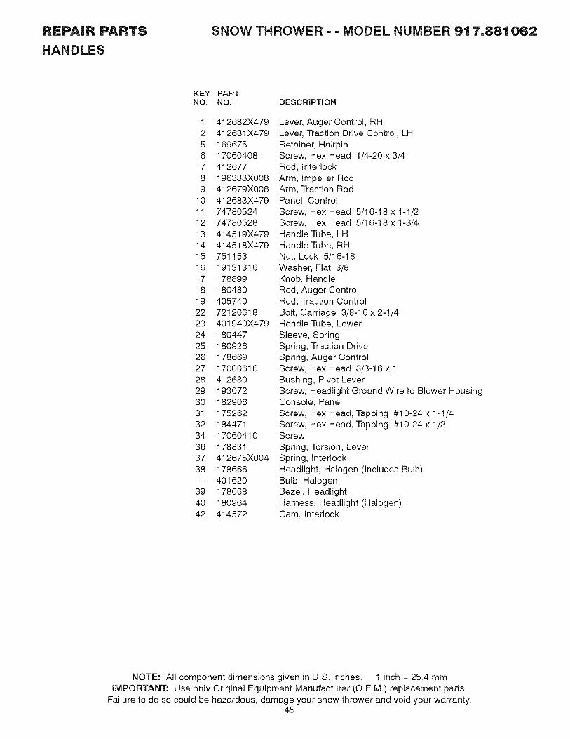
REPAIR PARTS
HANDLES
SNOW THROWER - - MODEL NUMBER 9t 7,881062
KEY PARTNO. NO. DESCRiPTiON
1 412682X4792 412681X4795 1696756 170604087 4126778 196333X0089 412679X008
10 412683X47911 7478052412 7478052813 414519X47914 414518X47915 75115316 1913131617 17889918 18048019 40574022 7212061823 401940X47924 18044725 18092626 17866927 1700061628 41268029 19307230 18290631 17526232 18447134 1706041036 17883137 412675X00438 178666-- 40162039 17866840 18096442 414572
Lever, Auger Control, RHLever, Traction Drive Control, LHRetainer, HairpinScrew, Hex Head 1/4-20 x 3/4Rod, InterlockArm, Impeller RodArm, Traction RodPanel, ControlScrew, Hex Head 5/16-18 x 1-1/2Screw, Hex Head 5/16-18 x 1-3/4Handle Tube, LHHandle Tube, RHNut, Lock 5/16-18Washer, Flat 3/8Knob, HandleRod, Auger ControlRod, Traction ControlBolt, Carriage 3/8-16 x 2-1/4Handle Tube, LowerSleeve, SpringSpring, Traction DriveSpring, Auger ControlScrew, Hex Head 3/8-16 x 1Bushing, Pivot LeverScrew, Headlight Ground Wire to Blower HousingConsole, PanelScrew, Hex Head, Tapping #10-24 x 1-1/4Screw, Hex Head, Tapping #10-24 x 1/2Screw
Spring, Torsion, LeverSpring, InterlockHeadlight, Halogen (Includes Bulb)Bulb, HalogenBezel, HeadlightHarness, Headlight (Halogen)Cam, Interlock
NOTE: All component dimensions given in U,S, inches, 1 inch = 25,4 mmiMPORTANT: Use only Original Equipment Manufacturer (O,E,M,) replacement parts,
Failure to do so could be hazardous, damage your snow thrower and void your warranty,45

REPAIR PARTS SNOW THROWER - - MODEL NUMBER 9t 7,881062
2
14
4
2
11
43
22
19
27
20
24
21
33
36
35
34
4
46
37

REPAIR PARTS
DRIVE
SNOW THROWER - - MODEL NUMBER 9t 7,881062
KEY PARTNO. NO. DESCRIPTION
1 401619 Chain, Drive2 751153 Nut, Lock 5/16-183 402882 Clip, Retainer4 17490508 Bolt, Hex Head 5/16-18 x 1/25 408981 Bearing, Flange6 12000007 E-Ring, Retainer9 402855 Sprocket & Shaft Assembly
11 402568 Rod, Clutch12 402187 Shaft, Hex13 402310 Pivot Rod, Shifter14 401732 Yoke, Shifter15 175344 Trunnion Bearing Assembly17 178613 Hub, Rubber Wheel18 198176X479 Plate, Rubber Wheel19 73930500 Nut, Lock 5/16-1820 179831 Ring, Rubber Wheel21 74760514 Screw, Hex Head 5/16-18 x 7/822 169675 Retainer, Hairpin23 180135 Spring, Bias24 402691 Sprocket, Axle Shaft25 402652 Pivot Rod, Swing Plate26 401820 Plate, Drive27 404307 Axle Shaft Assembly28 402504 Shaft, Friction Pulley29 401984X479 Bracket, Shifter, Speed31 17541008 Screw, Cap Head32 189282 Key, Square33 198791 Bearing, Ball34 402394 Plate, Swing35 402511 Spacer, Bearing36 402393 Pulley, Friction37 132010 Nut, Lock 5/16-1841 12000012 Ring, Retaining43 402878 Spring, Return44 9465MI Pin, Roll
NOTE: All component dimensions given in U,S, inches, 1 inch = 25,4 mmIMPORTANT." Use only Original Equipment Manufacturer (O,E,M,) replacement parts,
Failure to do so could be hazardous, damage your snow thrower and void your warranty,47

REPAIR PARTS
CHASSIS / ENGINE / PULLEYS
30
SNOW THROWER - - MODEL NUMBER 9t 7,881062
56
i ,,2. 4_,,, ,4{,, \_
19
29
31
32
36 \ 38
50 J11 J
3435
\
,/,/
,/52 /
12
45
44
51
11 \\
40
46
58
22
23
24
18 20
2627
7
15
//
/
48

REPAIR PARTS SNOW THROWER == MODEL NUMBER 9t 7,88t 062
CHASSIS / ENGINE / PULLEYS
KEY PART KEY PARTNO. NO. DESCRiPTiON NO. NO. DESCRiPTiON
1
2
3
414557180522
4 747805205 1500786 592897 1667858 1753309 416954
10 1004050011 17490508
12 41042013 8517914 17882815 40800716 15040617 18778618 7478052419 17533120 18052321 7461051622 40947523 18047824 17915725 40002626 85026327 851084
Spring, Traction idler 28Pulley, Idler (2-1/4) 29Engine, B&S, Model Number20M314-0927-E1 (See Breakdown) 30Screw, Hex Head 5/16-18 x 1-1/4 31Screw 32Washer, Flat 33Nut, Jam, Lock 5/16-18 34Pin, idler Pivot 35V-Belt, Traction Drive 36Washer, Lock 5/16 37Screw, Hex Washer Head 385/16-18 x 1/2 39Impeller Arm Assembly 40Retainer, Hairpin 41Spring, Brake 42V-Belt, impeller Drive 43Screw, Hex Head 3/8-16 x 1-1/4 44Arm, idler 45Screw, Hex Head 5/16-18 x 1-1/2 46Bushing, Idler Pivot 47Pulley, idler (2-3/4) 49Screw, Hex Head 5/16-24 x 1 50Spacer, Engine Pulley 51Pulley, Engine, Traction Drive 52Pulley, Engine, impeller Drive 53Washer, Flat 3/8 56Washer, Lock 3/8 57Screw, Hex Head 3/8-24 x 1-3/8 58
155452192213
17883017490408402881403096X004198580405485191730402856X004187101416717X004413429X47970027973930500403097X00417000616175324X479410877184471409346X615402685X61540610957079193071417015X61511050500198563
Guide, BeltBelt Cover Assembly(includes Toolbox Cover)Cover, ToolboxScrew, Hex Head 1/4-20 x 1/2Bolt, Shoulder 5/16-18Bellcrank ShifterClevis PinArm, Auger ControlLocknut, HexPlate, ClutchLink, Speed ControlBracket, ClutchBracket, TractionHairpin, Cotter 3/32 x 1/2Locknut, HexPlate, ShifterScrew, Hex HeadPivot Bracket, impeller Idler ArmPan, Frame BottomScrewFrame AssemblyPlate, Frame EndShaft, Auger ControlWasher, HardenedKey, SafetyMounting Plate, EngineWasher, Lock, External ToothPower Cord
NOTE: All component dimensions given in U,S, inches, 1 inch = 25,4 mmiMPORTANT: Use only Original Equipment Manufacturer (O,E,M,) replacement parts,
Failure to do so could be hazardous, damage your snow thrower and void your warranty,49

REPAIR PARTS
WHEELS / DECALS
314
8
SNOW THROWER - - MODEL NUMBER 9t 7,88t062
22
/ 24/ 23
33
9
28
/f
26 2925 11
10
20
2\,
\
\
2
18 307
16_#_ 34 _\_
F / \
19 '-%.__ 32
34 2429
25
14 28', \
50
22
2133
23
43
o /2
1110
1

REPAIR PARTS
WHEELS / DECALS
KEYNO.
1
2
34
7
89
10
1112
13
1415
16
17
18
19
20
21
22
23
24
25
26
27
28
293O
31
3233
34
SNOW THROWER - - MODEL NUMBER 9t 7,881062
PARTNO.
196752X417155443405161184471170604104102944102931760040617490508405077193506X479182015194944X008194939X008194943X00818184785179179148X479192126182466187622194941179139194940189282174697179830193885196753X41770027912000045146315
DESCRIPTION
Wheel Assembly, 16", Power Steering, LHPin, Klik 1/4Cover, Power SteeringScrew, Hex Head #10-24 x 1/2Screw, Hex Head 1/4-20 X .62Bracket, Steering Cable, RHBracket, Steering Cable, LHScrew, Hex Head 1/4-20 x 3/8Screw, Hex Head 5/16-18 x 1/2Link, Steering LeverLever Assembly, SteeringPin, Steering LeverBellcrank
Bracket Assembly, LH SteeringBracket Assembly, RH SteeringPin, Steering BellcrankRetainer, HairpinBracket, Lever AssemblyDriver, WheelRing, Wire RetainerLobe, WheelSlide, ClutchSpring, Clutch SlideLobe, AxleKey, Square 1/4 x .875Washer, Thrust (1")Bearing, AxleSpring, Return, Steering LatchWheel Assembly, 16", Power Steering, RHClip, RetainerRing, RetainingScrew, Hex Head, Tapping 5/16-18 x 5/8
KEYNO,
PARTNO.
1 1810382 4147433 1810344 1810415 1838766 1810329 415476
10 18372911 41539912 415398- - 416806
DESCRIPTION
Decal, DangerDecal Craftsman, 30"Decal Danger, DeflectorDecal DangerDecal CraftsmanDecal Instruction
Decal Speed ControlDecal Remote Deflector
Decal LH TriggerDecal RH TriggerOwner's Manual
NOTE: All component dimensions given in U,S, inches, 1 inch = 25,4 mmiMPORTANT: Use only Original Equipment Manufacturer (O,E,M,) replacement parts,
Failure to do so could be hazardous, damage your snow thrower and void your warranty,51

BRIGGS & STRATTON 4-CYCLE ENGINE MODEL NUMBER 20M314o0927=E1
307 _ 1J
8 / _qT_842
287_J2SI _ _
524
306
1351
J
741,
24_
725
1298_
21@
22
1095 VALVE GASKET SET
51A,
sss (_ ss3%
552_718 15A _718A
_329 REPLACEMENT ENGINE_
48 SHORT BLOCK I
358 ENGINE GASKET SET
20@
12
868 (_
51A
163 %
1022
52

BRIGGS & STRATTON 4-CYCLE ENGINE MODEL NUMBER 20M314o0927=E1
868 (_
51A(
36
1171
1(
383_
337 J
635 (_
e14
45
51A_
135
117
369
105
_ 1_7(_
1127 ?
121 CARBURETOR OVERHAUL KIT
127 0137 (_
104 _ 163 %105 [_
117
51A_
633 @
977 CARBURETOR GASKET SET
_J 51A( 163
%633 @
137
53

BRIGGS & STRATTON 4-CYCLE ENGINE MODEL NUMBER 20M314o0927=E1
727 732 472
610
990
53
1196
_668 _251A
1288
1011
11%976 1352
1252_1251
613A_
613
828
347_
731I 1036 EMISSIONS LABEL I
597 _(_
486 684980_
1211
3O4 697_
305_
721 957
366
100E
1070
309
455
930
332334 ,_
881¢;
1119 ,_
54

BRIGGS & STRATTON 4-CYCLE ENGINE MODEL NUMBER 20M314=0927-E1
281
1230 4_
222
188#_
604A i
564 _J,_
163 "<_D_,
1227 I ....._, -_-_._/s ¸ _- _:L_:__o_ <,_=,....
I 278 C_' 505 _?
209616
604
55

BRIGGS & STRATTON 4-CYCLE ENGINE MODEL NUMBER 20M314-0927=E1
KEY PART KEY PARTNO. NO. DESCRIPTION NO. NO. DESCRIPTION
1 794849 Cylinder Assembly 108 6967362 698340 Kit-Bushing/Seal (Magneto Side) 109 7935203 391086s • Seal-Oil (Magneto Side) 117 696134 O5 794871 Head-Cylinder 118 696135 O7 694872 .+ Gasket-Cylinder Head 121 69614611 696750 Tube-Breather 122 694876 O $12 694953 • Gasket-Crankcase 125 79316113 794829 Screw (Cylinder Head) 127 690727 O15 695757 Plug-Oil Drain 130 69613915A 691686 Plug-Oil Drain 133 69491416 794720 Crankshaft 135 69614218 791965 Cover-Crankcase 137 695426 O19 698340 Kit-Bushing/Seal (PTO Side) 146 69097920 391086s • Seal-Oil (PTO Side) 163 692277 +21 281658s Cap-Oil Fill 187 69808022 794825 Screw (Crankcase Cover/Sump) 188 69947923 794812 Flywheel 190 69212724 222698s Key-Flywheel 192 69008325 793561 Piston Assembly (Standard) 209 695491
792144 Piston Assembly (.020" Oversize) 219 69357826 792026 Ring Set (Standard) 220 691724
792073 Ring Set (.020" Oversize) 222 79480127 690975 Lock-Piston Pin 227 69486428 696581 Pin-Piston 278 79200829 694691 Rod-Connecting 281 69726830 694692 Dipper-Connecting Rod 287 69962932 690976 Screw (Connecting Rod) 300 79494733 499596 Valve-Exhaust 304 79147934 792200 Valve-Intake 305 69948035 694865 Spring-Valve (Intake) 306 69724036 694865 Spring-Valve (Exhaust) 307 79482242 499586 Keeper-Valve 309 79352445 690977 Tappet-Valve 332 79482446 790958 Camshaft 333 49234148 794910 Short Block 334 69947751 694874.+ O_ Gasket-Intake 337 491055s51A 694875.+ O$ Gasket-Intake 347 69833853 795017 Stud (Carburetor) 356 69260355 696710 Housing-Rewind Starter 358 69771558 693389 Rope-Starter (Cut to Required 369 695422
Length) 383 19374s60 695740 Grip-Starter Rope 455 79501195 690718 Screw (Throttle Valve) 456 69229997 696387 Shaft-Throttle 459 281505s98 695408 O Kit-Idle Speed 472 791948104 694918 O Pin-Float Hinge 474 793640105 696136 O Valve-Float Needle 505 691251
Valve-ChokeShaft-ChokeJet-Main (Standard)Jet-Main (High Altitude)Kit-Carburetor OverhaulSpacer-CarburetorCarburetorPlug-WelchValve-ThrottleFloat-CarburetorTube-Fuel TransferGasket-Float BowlKey-Timing
O$ Gasket-Air CleanerLine-FuelScrew (Control Bracket)Screw (Fuel Tank)Adjuster-Rocker ArmSpring-GovernorGear-GovernorWasher (Governor Gear)Bracket-ControlLever-Governor ControlWasher (Governor Control Lever)Panel-ControlScrew (Dipstick Tube)MufflerHousing-BlowerScrew (Blower Housing)Shield-CylinderScrew (Cylinder Shield)Motor-StarterNut (Flywheel)Armature-MagnetoScrew (Magneto Armature)Plug-SparkSwitch-RockerWire-StopGasket Set-EngineSpring-Float BowlWrench-Spark PlugCup-FlywheelPlate-Pawl FrictionPawI-RatchetKnob-Choke ShaftAlternatorNut (Governor Control Lever)
56

BRIGGS & STRATTON 4-CYCLE ENGINE MODEL NUMBER 20M314=0927=E1
KEY PART KEY PARTNO. NO, DESCRIPTION NO. NO, DESCRIPTION
523 790477
524 691876
525 792041
528 793006
529 791822
552 694674
562 793216
564 699854
578 792576
597 691696
601 791850
604 696758
604A 790473
608 699335
610 794541
613 794846
613A 794844
615 694676
616 694675
632 695917
633 690998 O635 691909
663 699854
668 794539
676 697816
677 699776
689 691855
697 795012
718 690959
718A 695178
725 696756
727 697465
731 793621
731A 794540
732 699200
741 691288
742 692564
746 694679
798 697890
842 795015
847 790476
851 692424
868 794086 "+
883 695398 "+
892 791944
914 794827
Dipstick 930 696709SeaI-O Ring (Dipstick Tube) 957 694261Tube-Dipstick 972 694260Hose-Primer 975 696138Grommet 976 790221Bushing-Governor Crank 977 696147Bolt (Governor Control Lever) 990 695756Screw (Control Cover) 998 792928Wire Assembly 1005 794815Screw (Pawl Friction Plate) 1011 794544Clamp-Hose 1022 690971 .+Cover-Control 1023 698042Cover-Control 1026 695177Starter-Rewind 1029 690972Attester-intake 1036Screw (Muffler)Screw (Muffler)Retainer-Governor Shaft 1070 794821Crank-Governor 1095 695440Spring/Link-Mechanical 1100 791959Governor 1119 699772Seal-Choke/Throttle Shaft 1127 695407Boot-Spark Plug 1171 794828Screw (Control Panel) 1196 696692Spacer 1210 498144Deflector-Muffler 1211 498144Screw (Muffler Deflector) 1230 699847Spring-Friction 1251 696762Screw (Starter Motor) 1251A790471Pin-Locating 1252 699480Pin-Locating 1288 696757Shield-Heat 1298 795016Cover-Starter Drive 1318 794838Hood-Snow 1329 20P414-0015Hood-SnowScrew (Starter Drive Cover)Gear-TimingRetainer-E RingGearqdler 1351 794847Screw (Rocker Cover)SeaI-O Ring (Dipstick Tube)Dipstick/Tube Assembly (_Terminal-Spark Plug $Seal-Valve +Gasket-ExhaustSwitch-KeyScrew (Rocker Cover)
Guard-RewindCap-FuelTank-FuelBowl-FloatPrimer-CarburetorGasket Set-CarburetorKey SetPipe-OilFan-FlywheelTube-VentGasket-Rocker CoverCover-RockerRod-PushArm-RockerLabel-Emissions (Available froman authorized Briggs & StrattonService Dealer)Screw (Flywheel Fan)Gasket Set-ValvePivot-Rocker ArmScrew (Alternator)Screw (Float Bowl)Stud (Rocker Arm Cover)Screw (SnowPulley/SpringPulley/SpringStud (ControlShield-SnowShield-Snow
Hood)
Assembly (Pulley)
Assembly (Spring)
Bracket)
Screw (Snow Shield)Nut (Snow Hood)Nut (Heat Shield)Knob-Snow HoodReplacement Engine (TransferMuffler and/or Spark AttesterAssembly from the original engineif suitable for additional serviceor add new parts as required).Stud (Cylinder Shield)
Included in Engine Gasket Set, Key. No. 358Included in Carburetor Overhaul Kit, Key. No. 121Included in Carburetor Gasket Set, Key. No. 977Included in Valve Gasket Set, Key. No. 1095
NOTE: All component dimensions given in U,S, inches1 inch = 25,4 mm
57

RVICE OTES
58

ERVICE OTES
59

Your Home
For repair - in your home - of all major brand appliances,
lawn and garden equipment, or heating and cooling systems,no matter who made it, no matter who sold it!
For the replacement parts, accessories and
owner's manuals that you need to do-it-yourself.
For Sears professional installation of home appliances
and items like garage door openers and water heaters.
1-800-4-MY-HOME ® Anytime, day or night
(1-800-469-4663) (U.S.A. and Canada)www.sears.com www.sears.ca
Our Home
For repair of carry-in products like vacuums, lawn equipment,and electronics, call or go on-line for the nearest
Sears Parts and Repair Center.
1-800-488-1222 Anytime, day or night (U.S.A. only)
www.sears.com
To purchase a protection agreement (U.S.A.)or maintenance agreement (Canada) on a product serviced by Sears:
1-800-827-6655 (U.S.A.) 1-800-361-6665 (Canada)
Para pedir servicio de reparaci6n
a domicilio, y para ordenar piezas:
1.-888-SU-HOGAR ®
(1-888-784-6427)
Au Canada pour service en fran(_ais:
1-800-LE-FOYER Mc
(1-800-533-6937)www.sears.ca
Serifs© Sears Brands, LLC
® Registered Trademark / TMTrademark / SMService Mark of Sears Brands, LLC
® Marca Registrada / TMMarca de Fabrica / SMMarca de Servicio de Sears Brands, LLC
MCMarque de commerce / MDMarque depos6e de Sears Brands, LLC
416806 Rev 5 11,29,07 TH Printed in the U,S,A.


![Portable ProductsRAC °] 7500 › mmh › lis_pdf › OWNM › L0403232.pdf · GENPortable ProductsRAC °] 7500 Portable Generator Owner's Manual Model No. 1315-0 (7,500 Watt AC Generator)](https://img.dokumen.tips/doc/110x75/5f204288361a060b480a464d/portable-productsrac-7500-a-mmh-a-lispdf-a-ownm-a-l0403232pdf-genportable.jpg)