Embed Size (px)
Citation preview

Owner’s Manual and Service Guide
Star Classic, Star Sport, SS Limited, H-Series

2
Thanks for buying your Star EV. This manual contains information you will need for proper operation, maintenance, and care of your Star EV. A thorough understanding of these simple instructions will help you to obtain maximum enjoyment from your new Star EV.
If you have any questions about the operation or maintenance of your Star, please consult your Star EV dealer.
Read and understand this manual completely before operating your Star EV.
This manual should be considered a permanent part of your Star EV and should remain with the vehicle when lending or resold.

3
Models & Names
Vehicle Specifications
OverviewImportant labels
ControlsFunctions
Safety
Operation
MaintenanceBattery maintenanceCharger maintenanceMotor maintenanceController maintenanceRear axle maintenanceWheel maintenanceBrake adjustmentLubrication
Troubleshooting
Periodic Maintenance Chart
Storage
Table of Contents
4
7
11
1215
17
18
1925262729293030
32
32
34

4
Important Information
Particularly important information is distinguished by the following notations:
WARNING: Failure to follow Warning instructions could result in severe injury to the vehicle occupants, bystanders or persons inspecting or repairing the vehicle.
CAUTION: Failure to follow Caution instructions could cause damage to the vehicle.
Special Notice: Because the seat & backrest wrapping film may stick to the seat vi-nyl and cause seat vinyl to fade or stain, remove the seat & backrest wrapping film when you start to use the vehicle. Even if you plan to store the vehicle for a long time, remove the seat & backrest wrapping film.
1: Models and Names* Some models are shown with options like one-piece windshields and custom wheels.
Classic 36-2 Classic 36-2+2
Classic 48-2 Classic 48-2+2

5
Classic 48-4 Classic 48-4+2
Classic 48-6 Classic 48-6+2
Classic 36-2H, Classic 48-2H Classic 48-4H
Classic 48-6H Classic 48-2HCX (with various box attachment options, not shown)

6
Classic 48-4HCX (with various box attachment options, not shown) Sport 2+2
Sport 4+2 Sport 48-2H
Sport 48-4H Sport 48-2HCX

7
Star Classic Classic 36-2 and Classic 36-2+2
Passengers 2 or 4 (2 facing backward) Body Material Plastic
Battery System Six 6 V (36 V) batteries, Trojan T-105 Front Suspension Leaf spring and shock
Motor Power 4 hp Advanced DC motor Steering System Rack and pinion
Controller Power 300 A Curtis programmable controller Brake System Rear drum
Top Speed 18 mph Tire Size 205/50/10, 4-ply DOT tire
Load Capacity 36-2: 600 lbs / 36-2+2: 660 lbs Tire Pressure 30 psi
Dimensions36-2: 94” x 47” x 72” (L x W x H) 36-2+2: 115” x 47” x 77” (L x W x H)
Wheel Type 10” aluminum
Weight w/ Batteries 36-2: 1075 lbs / 36-2+2: 1245 lbs Roof
36-2: Molded plastic, beige36-2+2: Fiberglass, col-or-matched
Ground Clearance 5” Windshield Foldable, tinted
Turning Radius 10 ft Drive Train Direct rear drive with 10.25:1 ratio
Wheel Base 67” Voltage Reducer 20 A, 36 V to 12 V reducer included
Top Climbing Grade 36-2: 25%36-2+2: 20% Warranty
Four year limited warranty, two year bumper-to-bumper warranty (less wear items)
Star Classic Classic 48-2 and Classic 48-2+2
Passengers 2 or 4 (2 facing backward) Body Material Plastic
Battery System Eight 6 V (48 V) batteries, Trojan T-105 Front Suspension Leaf spring and shock
Motor Power 5.5 hp Advanced DC motor Steering System Rack and pinion
Controller Power 400 A Curtis programmable controller Brake System Rear drum
Top Speed 19.5 mph (20-25 mph if street legal) Tire Size 205/50/10, 4-ply DOT tire
Load Capacity 48-2: 600 lbs / 48-2+2: 660 lbs Tire Pressure 30 psi
Dimensions48-2: 94” x 47” x 72” (L x W x H) 48-2+2: 115” x 47” x 77” (L x W x H)
Wheel Type 10” aluminum
Weight w/ Batteries 48-2: 1200 lbs / 48-2+2: 1370 lbs Roof
48-2: Molded plastic, beige48-2+2: Fiberglass, col-or-matched
Ground Clearance 5” Windshield Foldable, tinted
Turning Radius 10 ft Drive Train Direct rear drive with 10.25:1 ratio
Wheel Base 67” Voltage Reducer 20 A, 48 V to 12 V reducer included
Top Climbing Grade 20% WarrantyFour year limited warranty, two year bumper-to-bumper warranty (less wear items)
2: Vehicle Specifications
8
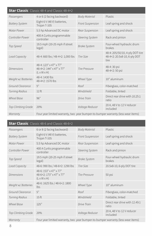
Star Classic Classic 48-4 and Classic 48-4+2
Passengers 4 or 6 (2 facing backward) Body Material Plastic
Battery System Eight 6 V (48 V) batteries, Trojan T-105 Front Suspension Leaf spring and shock
Motor Power 5.5 hp Advanced DC motor Rear Suspension Leaf spring and shock
Controller Power 400 A Curtis programmable controller Steering System Rack and pinion
Top Speed 19.5 mph (20-25 mph if street legal) Brake System Four-wheel hydraulic drum
brakes
Load Capacity 48-4: 660 lbs / 48-4+2: 1,000 lbs Tire Size48-4: 205/50/10, 4-ply DOT tire48-4+2: 20.5x8-10, 6-ply DOT tire
Dimensions48-4: 123” x 47” x 77”48-4+2: 144” x 47” x 77”(L x W x H)
Tire Pressure 48-4: 30 psi48-4+2: 50 psi
Weight w/ Batteries 48-4: 1430 lbs48-4+2: 1570 lbs Wheel Type 10” aluminum
Ground Clearance 5” Roof Fiberglass, color-matched
Turning Radius 12 ft Windshield Foldable, tinted
Wheel Base 96” Drive Train Direct rear drive with 10.25:1 ratio
Top Climbing Grade 20% Voltage Reducer 20 A, 48 V to 12 V reducer included
Warranty Four year limited warranty, two year bumper-to-bumper warranty (less wear items)
Star Classic Classic 48-6 and Classic 48-6+2
Passengers 6 or 8 (2 facing backward) Body Material Plastic
Battery System Eight 6 V (48 V) batteries, Trojan T-105 Front Suspension Leaf spring and shock
Motor Power 5.5 hp Advanced DC motor Rear Suspension Leaf spring and shock
Controller Power 400 A Curtis programmable controller Steering System Rack and pinion
Top Speed 19.5 mph (20-25 mph if street legal) Brake System Four-wheel hydraulic drum
brakes
Load Capacity 48-6: 990 lbs / 48-6+2: 1290 lbs Tire Size 20.5x8-10, 6-ply DOT tire
Dimensions48-6: 153” x 47” x 77” 48-6+2: 173” x 47” x 77”(L x W x H)
Tire Pressure 50 psi
Weight w/ Batteries 48-6: 1625 lbs / 48-6+2: 1800 lbs Wheel Type 10” aluminum
Ground Clearance 5” Roof Fiberglass, color-matched
Turning Radius 15 ft Windshield Foldable, tinted
Wheel Base 125” Drive Train Direct rear drive with 12.49:1 ratio
Top Climbing Grade 20% Voltage Reducer 20 A, 48 V to 12 V reducer included
Warranty Four year limited warranty, two year bumper-to-bumper warranty (less wear items)

9
Sport Sport 2+2 and Sport 4+2
Passengers 4 of 6 (2 facing backwards on both) Body Material Plastic
Battery System Eight 6 V (48 V) batteries, Trojan T-105 Front Suspension Leaf spring and shock
Motor Power 5.5 hp Continuous Rear Suspension Leaf spring and shock
Controller Power 400 A Curtis controller Steering System Rack and pinion
Top Speed 17 mph (20-25 mph if street legal) Brake System Rear drum
Load Capacity 2+2: 600 lbs / 4+2: 900 lbs Tire Size 23x10.5-12 DOT tire
Dimensions 2+2: 116” x 52” x 79” (L x W x H) 4+2: 138” x 52” x 85” (L x W x H) Tire Pressure 15 psi
Weight w/ Batteries 2+2: 1430 lbs / 4+2: 1650 lbs Wheel Type 12” steel
Ground Clearance 7" Roof Fiberglass, color-matched
Turning Radius 2+2: 10 ft / 4+2: 13 ft Windshield Foldable, tinted
Wheel Base 2+2: 68” / 4+2: 96” Drive Train Direct rear drive with 12:1 ratio
Top Climbing Grade 28% Voltage Reducer 20 A, 48 V to 12 V reducer included
Warranty Four year limited warranty, two year bumper-to-bumper warranty (less wear items)
H-Series Classic 36-2H, 48-2H, 48-4H, and 48-6H
Passengers 2, 4, or 6 Top Climbing Grade 36- and 48-2H: 25% / 48-4H and 6H: 20%
Battery System36 V: Six 6 V batteries, Trojan T-105 / 48 V: Eight 6 V batteries, Trojan T-105
Brake System 36- and 48-2H: Rear drum 48-4H and 6H: Hydraulic drum
Motor Power36 V: 4 hp Advanced DC motor48 V: 5.5 hp Advanced DC motor
Tire Size36-2H, 48-2H, 4H: 205/50/10, 4-ply DOT48-6H: 20.5 x 8x 10, 6-ply DOT
Controller Power 36 V: 300 A / 48 V: 400 A Tire Pressure 36-2H, 48-2H, 4H: 30 psi / 48-6H: 50 psi
Top Speed36 V: 18 mph48 V: 19.5 mph (20-25 mph if street legal)
Roof36- and 48-2H: Molded plastic, beige / 48-4H and 6H: Fiber-glass, color-matched
Total Load Capacity 36- and 48-2H: 650 lbs / 48-4H: 960 lbs 48-6H: 990 lbs Drive Train
36- and 48-2H: Direct rear drive, 10.25:1 / 48-4H and 6H: Direct rear drive, 12.49:1
Cargo Capacity 300 lbs Front Suspension Leaf spring and shock
Body Material Plastic Rear Suspension Leaf spring and shock
Dimensions36- and 48-2H: 115” x 47” x 72”48-4H: 144” x 47” x 77”48-6H: 153” x 47” x 77”
Weight w/ Batteries36-2H: 1100 lbs / 48-2H: 1230 lbs / 48-4H: 1460 lbs / 48-6H: 1800 lbs
Box Dimensions 30” x 43” x 8.5” (L x W x H) Wheel Type 10” aluminum
Turning Radius 36- and 48-2H: 10 ft / 48-4H: 12 ft / 48-6H: 15 ft Wheel Base 36- and 48-2H: 67” / 48-4H: 96”
/ 48-6H: 125”
Ground Clearance 5” Steering System Rack and pinion
Windshield Foldable, tinted Voltage Reducer 20 A, 48 V or 36 V to 12 V reduc-er included
Warranty Four year limited warranty, two year bumper-to-bumper warranty (less wear items)

10
H-Series Classic 48-2HCX, Classic 48-4HCX
Passengers 2 or 4 Top Climbing Grade 20%
Battery System Eight 6 V batteries, Trojan T-105 Brake System Hydraulic drum
Motor Power 5.5 hp Advanced DC motor Tire Size 20.5 x 8x 10, 6-ply DOT
Controller Power 400 A Tire Pressure 50 psi
Top Speed 19.5 mph (20-25 mph if street legal) Roof
2HCX: Molded plastic, beige 4HCX: Fiberglass, color-matched
Load Capacity 2HCX: 960 lbs / 4HCX: 1290 lbs Drive Train Direct rear drive, 12.49:1
Cargo Capacity 2HCX: 600 lbs / 4HCX: 800 lbs Front Suspension Leaf spring and shock
Body Material Plastic Rear Suspension Leaf spring and shock
Dimensions2HCX: 132" x 47" x 73"4HCX: 162" x 47" x 78"(L x W x H)
Weight w/ Batteries 2HCX: 1500 lbs4HCX: 1625 lbs
Box Dimensions 54" x 43" x 9.5" (L x W x H) Wheel Type 10” aluminum
Turning Radius 2HCX: 12 ft / 4HCX: 15 ft Wheel Base 2HCX: 96” / 4HCX: 125”
Ground Clearance 5” Steering System Rack and pinion
Windshield Foldable, tinted Voltage Reducer 20 A, 48 V to 12 V reducer included
Warranty Four year limited warranty, two year bumper-to-bumper warranty (less wear items)
H-Series Sport 48-2H, Sport 48-4H, Sport 48-2HCX
Passengers 2 or 4 Top Climbing Grade
Battery System Eight 6 V batteries, Trojan T-105 Brake System
Motor Power 5.5 hp Advanced DC motor Tire Size
Controller Power 400 A Tire Pressure
Top Speed 19.5 mph (20-25 mph if street legal) Roof
Load Capacity 2H: 600 lbs / 4H: 930 lbs Drive Train
Cargo Capacity 2H: 300 lbs / 4H: 330 lbs Front Suspension
Body Material Plastic Rear Suspension
Dimensions Weight w/ Batteries
Box Dimensions Wheel Type
Turning Radius Wheel Base
Ground Clearance Steering System Rack and pinion
Windshield Foldable, tinted Voltage Reducer 20 A, 48 V to 12 V reducer included
Warranty Four year limited warranty, two year bumper-to-bumper warranty (less wear items)

11
3: Overview
WARNING: Always confirm whether there are restrictions in the area where you in-tend to use the vehicle. It is recommended that only people who possess a valid motor vehicle driver’s license be allowed to operate golf cars.
Important Labels
Safety LabelRead carefully and understand the contents on the safety label. The label is at-tached on the dash panel.
Vehicle InformationThe name plate is either on the back of the seat pod or below the dashboard.

12
Chassis number of the vehicle
4: Controls
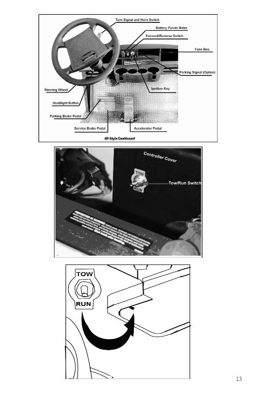
Note: There are two types of dashboards on STAR . The cup holder on the 2008 and later (current) style dashboard is on top of the instrument panel and the cup holder on the 2006 style dashboard is below the instrument panel.
13

14
15
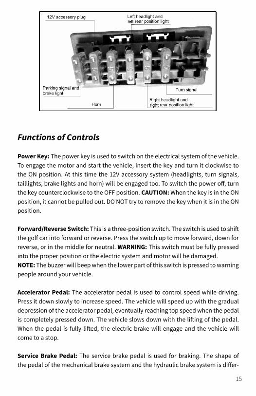
Functions of Controls
Power Key: The power key is used to switch on the electrical system of the vehicle. To engage the motor and start the vehicle, insert the key and turn it clockwise to the ON position. At this time the 12V accessory system (headlights, turn signals, taillights, brake lights and horn) will be engaged too. To switch the power off, turn the key counterclockwise to the OFF position. CAUTION: When the key is in the ON position, it cannot be pulled out. DO NOT try to remove the key when it is in the ON position.
Forward/Reverse Switch: This is a three-position switch. The switch is used to shift the golf car into forward or reverse. Press the switch up to move forward, down for reverse, or in the middle for neutral. WARNING: This switch must be fully pressed into the proper position or the electric system and motor will be damaged.NOTE: The buzzer will beep when the lower part of this switch is pressed to warning people around your vehicle.
Accelerator Pedal: The accelerator pedal is used to control speed while driving. Press it down slowly to increase speed. The vehicle will speed up with the gradual depression of the accelerator pedal, eventually reaching top speed when the pedal is completely pressed down. The vehicle slows down with the lifting of the pedal. When the pedal is fully lifted, the electric brake will engage and the vehicle will come to a stop.
Service Brake Pedal: The service brake pedal is used for braking. The shape of the pedal of the mechanical brake system and the hydraulic brake system is differ-

ent: refer to the figures below. NOTE: On the mechanical brake system, the service brake pedal is combined with the parking brake pedal.
Parking Brake Pedal: The parking brake pedal is used in braking for parking. The parking brake of the mechanical brake system is different from hydraulic brake sys-tem. The parking brake of mechanical brake system is engaged by foot as shown in above picture (refer to ‘Mechanical Brake’). The parking brake of the hydraulic brake system is engaged by hand as shown in the figure below. The parking brake should be engaged into parking position whenever the vehicle is left unattended.
How to engage and disengage the parking brake
Mechanical brake system • To engage the parking brake, press down the service brake pedal com-
pletely, then press down the parking brake pedal until it locks.• To disengage the parking brake, press down the service brake pedal until
the parking brake pedal is unlocked.• WARNING: The foot park brake will automatically release when the accel-
erator pedal is stepped down. If the power key is in ON position, stepping down the accelerator pedal may suddenly cause the vehicle to move.
Hydraulic brake system• To engage the parking brake, pull up the hand brake lever to the end.• To disengage the parking brake, pull the hand brake lever up completely
and press the button on the top of the brake lever. Return the brake lever to the down position.
• WARNING: Always release the brake handle completely before driving the vehicle. Do not press both the brake pedal and the accelerator together; this will damage the motor.
Steering Wheel: The steering wheel is used to control the driving direction. Avoid sudden and sharp turns.
Battery Power Meter: There are 10 calibration marks on the meter. The meter will decline from the top to the bottom as the battery discharges. When the battery is too low, the red indicator light will flash, reminding you to recharge the battery. NOTE: Refer to your Battery Charger’s Owners Manual for how to recharge the bat-teries.
16

17
Tow/Run Switch (available for Curtis 1266 and 1268 controller): Before oper-ating the vehicle, make sure the TOW/RUN switch is on ‘RUN’ position. Make sure the TOW/RUN switch is on the “TOW’ position if towing the vehicle. The TOW/RUN switch is located under the seat on the passenger side either on the controller cover or just under the rear body as shown on p. 13. WARNING: Whenever the TOW/RUN switch is moved from the RUN position to the TOW position, move it back to the RUN position, there is a delay of approximately 30 seconds before the vehicle will run.
Turn Signal/Horn Switch: This switch is used to operate the turn signals and horn.• Lift up the handle lever to activate the horn.• Push the handle lever up to activate the right turn signal.• Pull the handle lever down to activate the left turn signal.
Headlight Switch: Pull out the button to switch on the headlight.
5: Safety
Star EVs are designed for simple operation; however, make sure you observe the following safe operation instructions.
Before operating:• Read the user manual thoroughly before operating the vehicle.• Allow only authorized people to operate the vehicle, and only from the
driver’s side.• Drive the vehicle only in areas where it is allowed by law or local regula-
tions. • DO NOT allow more people than is permitted on the vehicle.• DO NOT overload the vehicle, otherwise the motor may be damaged. The
vehicle may also lose control and/or the driver and passengers will be in danger if overloaded.
• DO NOT operate the vehicle under the influence of alcohol or drugs. • DO NOT climb any slope steeper than the vehicle’s climbing ability.• DO NOT overtake other vehicles at crossroads, in blind spots or in any dan-
gerous areas.

During operation:• Keep your entire body inside the vehicle, keep seated and hold on while
the vehicle is moving.• Do not start the vehicle until all occupants are securely seated. • Keep your hands on the steering wheel and your eyes on the path ahead. • Always back up slowly, and watch carefully.• Avoid starting or stopping suddenly.• Avoid turning the steering wheel sharply at high speed.• Always drive slowly up or down on a slope.• Do not make any modification or addition which may affect the safety of
the vehicle.
6: Operation
Starting1. With the Forward/Reverse switch on the Neutral position, turn the power key
to ON position. • CAUTION: The car will not run if the F/R switch is set to Forward or Reverse
position before turning the key to the ON position.• WARNING: Do not step down the accelerator pedal when turning the pow-
er key. Otherwise, the vehicle may suddenly start moving.2. With the parking brake applied, press the Forward/Reverse switch and lock it
in the desired position.• CAUTION: Do not shift from Forward to Reverse while the vehicle is mov-
ing.3. Make sure that your path is clear. If the vehicle is equipped with the mechanic
braking system, press the lower section of the brake pedal to release the park brake, and slowly press down the accelerator pedal. If the vehicle is equipped with the hydraulic brake system, release the hand brake first before you press the accelerator pedal. • CAUTION: If the vehicle is equipped with mechanical brake system, press-
ing the accelerator pedal will release the parking brake if it is engaged. Pressing the accelerator pedal is not the preferred method of releasing the parking brake. Pressing the lower section of the brake pedal is the pre-ferred method of releasing the parking brake to assure the longest service life of brake components. If the key switch is ‘ON’ and parking brake is set, pressing the accelerator inadvertently will release the parking brake and
18

19
will cause the vehicle to move which could cause severe injury or death. • CAUTION: If the accelerator pedal is stepped down before the power key is
on, the vehicle will not run. In this case, you should release the accelerator pedal first, and then turn the power key ON. Then, press down the acceler-ator pedal again, and the vehicle will start to move.
StoppingTo stop the vehicle, gradually press down the brake pedal. When the vehicle has come to a stop, apply the parking brake pedal and turn the power key to OFF and press the F/R switch on Neutral position. • CAUTION: Do not hold the vehicle on an incline with the accelerator: use
the brake.
7: Maintenance
Users should perform regular maintenance to ensure the vehicle is in good condi-tion.
Battery Maintenance
NOTE: STAR EVs are equipped with deep-cycle flooded lead-acid batteries. If your vehicle is equipped with another type of battery, follow the maintenance instruc-tions provided by the battery manufacturer. Below maintenance instruction is es-pecially for deep-cycle flooded lead-acid battery.
WARNING! Battery electrolyte is poisonous and dangerous, and may cause severe burns or injury. Always wear protective clothing, gloves, and goggles when han-dling batteries, electrolyte, and charging your battery. KEEP OUT OF REACH OF CHILDREN.
Cleaning1. The exterior of the battery, the connection wires and bolts should always be
kept clean and dry. When cleaning, make sure all vent caps are tightly in place. Clean the battery top with a cloth or brush and solution of baking soda and wa-ter. When cleaning, do not allow any cleaning solution or other foreign matter to get inside of the battery. This should be done every week.
20
2. Clean battery terminals and the inside of cable clamps using a post and clamp cleaner. Clean terminals will have a bright metallic shine. This should be done as needed.
3. Reconnect the clamps to the terminals and thinly coat them with petroleum jelly (Vaseline) to prevent corrosion. • WARNING! Before you disconnect any battery cable from any terminal on
the battery, always remove the power by disconnecting the main battery cable from the controller.
Checking the terminals and nuts: The connection of the batteries should be kept in good condition. Check the battery cable terminals and nuts weekly in order to prevent sparking or damage to terminals. A damaged battery cable should be re-placed immediately.
Battery compartment: Do not place any objects on the battery and do not con-nect the positive pole to the negative pole. This may cause a short circuit or danger-ous sparking. This can cause damage to the battery or injury to the user.
Recharging1. Regardless of how long you have used the vehicle, the battery should be re-
charged fully on the same day. Any delay on the re-charging will reduce the life of the battery. Note: The lead-acid battery does not develop a memory, so it need not be fully discharged before recharging.
2. If the vehicle is going to be kept unused for a long time, the battery should be fully recharged first. After that, the battery should be fully recharged every 2 weeks.
3. When driving, the driver should be aware of the drop level of the battery power from the battery power meter. The driver should estimate the distance needed to be taken, and recharge the battery at a proper time to ensure that the vehi-cle can get back to the charging location in time for recharging. • WARNING! Make sure the battery is recharged before the battery power
meter shows 20% is left. An over-discharged battery will have a very short service life.
• WARNING! During recharging, the vehicle should be parked in a well-ven-tilated area with filling caps tightly secured. Keep far away from any flame and sparks to avoid any explosion or fire that could cause physical injury or damage to property.

21
Battery water maintenanceFlooded batteries need water. Watering must be done at the right time and in the right amount or else the battery’s performance and longevity suffers.
Water should always be added after fully charging. Prior to charging, there should be enough water to cover the plates. If the battery has been discharged (partially or fully), the water level should also be above the plates. Keeping the water at the correct level after a full charge ensure that you will not have to worry about the water level at a different state of charge.
Depending on the local climate, charging methods, and application, Trojan recom-mends that batteries be checked once a month until you get a feel for how “thirsty” your batteries are.
Important things to remember:Do not let the plates become exposed to air. This will damage (corrode) the plates.Do not fill the water to the cap. This most likely will cause the battery to overflow acid, consequently losing capacity and causing a corrosive mess.Do not use water with a high mineral content. Use distilled water only.CAUTION: The electrolyte is a solution of acid and water so skin contact should be avoided.
Step by step watering procedure:1. Open the vent caps and look inside the filling wells.2. Check electrolyte level; the minimum level is at the top of the plates.3. If necessary add just enough water to cover the plates.4. Put batteries on a complete charge before adding water (refer to the Charging
section).5. Once charging is completed, open the vent caps and look inside the fill wells. 6. Add water until the electrolyte level is 1/8" below the bottom of the fill well.7. A piece of rubber can be used safely as a dipstick to help determine this level.8. Clean, replace, and tighten all vent caps.
WARNING! Never add acid to the battery.
TestingVisual inspection alone is not sufficient to determine the overall health of the bat-tery. Both open-circuit voltage and specific gravity readings can give a good indica-tion of the battery's charge level, life span, and health. Routine voltage and gravity checks will not only show the state of charge but also help spot signs of improper

22
care, such as undercharging and over-watering, and possibly even locate a bad or weak battery. The following steps outline how to properly perform routine voltage and specific gravity testing on batteries.
Specific Gravity Test (Flooded batteries only) 1. Do not add water.2. Fill and drain the hydrometer 2 to 4 times before pulling out a sample. 3. There should be enough sample electrolyte in the hydrometer to com-
pletely support the float.4. Take a reading, record, and return the electrolyte back to the cell.5. To check another cell, repeat the 3 steps above.6. Check all cells in the battery.7. Replace the vent caps and wipe off any electrolyte that might have been
spilled.8. Correct the readings to 80˚ F: Add .004 to readings for every 10˚ above 80˚
F, Subtract .004 for every 10˚ below 80˚ F. 9. Compare the readings.10. Check the state of charge using Table 1.
The readings should be at or above the factory specification of 1.277 +/- .007. If any specific gravity readings register low, then follow the steps below.
1. Check and record voltage level(s).2. Put battery(s) on a complete charge.3. Take specific gravity readings again.

23
If any specific gravity readings still register low then follow the steps below.1. Check voltage level(s).2. Perform equalization charge. Refer to the Equalizing section for the proper
procedure.3. Take specific gravity readings again.
If any specific gravity reading still registers lower than the factory specification of 1.277+/- .007 then one or more of the following conditions may exist:
1. The battery is old and approaching the end of its life.2. The battery was left in a state of discharge too long.3. Electrolyte was lost due to spillage or overflow.4. A weak or bad cell is developing.5. Battery was watered excessively previous to testing.
Batteries in conditions 1 - 4 should be taken to a specialist for further evaluation or retired from service.
Open-Circuit Voltage TestFor accurate voltage readings, batteries must remain idle (no charging, no dis-charging) for at least 6 hours, preferably 24 hours.
1. Remove all connections from the batteries.2. Measure the voltage with a DC voltmeter.3. Check the state of charge with Table 1.4. Charge the battery if it registers 0% to 70% charged.
If the battery value is lower than that in Table 1, the following conditions may exist: • The battery was left in a state of discharge too long.• The battery has a bad cell.
Batteries in these conditions should be taken to a specialist for further evaluation or retired from service.

24
Battery installationWARNING: When working with batteries, DO NOT put wrenches or any other met-al objects across the battery terminals. Otherwise, an arc can occur, and this can cause an explosion of the battery and physical injury. Only a qualified electrician should install or replace batteries.
Battery Charging NOTE: The standard charger on the vehicle is an onboard charger. It is either in-stalled in the rear bag well, under the seat, or under the front body. Sometimes the charger is not installed on the vehicle. For an onboard charger, a separate charging cord will be provided with the vehicle for connecting the charger and AC electricity.
WARNINGS• Before you use the charger, read the operation manual provided with the
charger. • Explosive hydrogen gas is produced while the battery is charged. Only
charge the battery in well-ventilated areas. • Before using the charger, check if the battery charger you are using is cor-
rectly rated as per your local AC electricity network. • When using a new battery, make sure the new battery has the same speci-
fications as the original and is appropriate in application.
Percentage of charge
Specific Gravity corrected to 80°F
Open-Circuit Voltage
6 V 8 V 12 V 24 V 36 V 48 V
100 1.277 6.37 8.49 12.73 25.46 38.20 50.93
90 1.258 6.31 8.41 12.62 25.24 37.85 50.47
80 1.238 6.25 8.33 12.50 25.00 37.49 49.99
70 1.217 6.19 8.25 12.37 24.74 37.12 49.49
60 1.195 6.12 8.16 12.24 24.48 36.72 48.96
50 1.172 6.05 8.07 12.10 24.20 36.31 48.41
40 1.148 5.98 7.97 11.96 23.92 35.87 47.83
30 1.124 5.91 7.88 11.81 23.63 35.44 47.26
20 1.098 5.83 7.77 11.66 23.32 34.97 46.63
10 1.073 5.75 7.67 11.51 23.02 34.52 46.03
State of charge as related to specific gravity and open circuit voltage

25
Charging Process1. Turn the power key to OFF.2. Connect the plug to the vehicle receptacle first; then connect it to your
local AC power outlet. • WARNING: Do not disconnect the cord from the battery receptacle
when the charger is ON, otherwise an arc could occur which may cause an explosion. Always disconnect the battery receptacle first, then disconnect from the AC power outlet.
3. The charger will turn off automatically when the battery is fully charged. • WARNING: The battery receptacle is combined with a security switch
which will cut off power to the vehicle when the battery is being charged. The vehicle cannot be started with the battery receptacle in use.
4. After the charger turns off, disconnect the plug on the AC charging cable from the AC power outlet first, then disconnect the cord from the vehicle receptacle.
Do not open the housing of the charger. Only a qualified electrician should open the housing of the charger. The charger should be stored in safe and dry room with good ventilation. The charger should be packed properly if not in use for an extend-ed time. Carefully read the operation manual for the charger for detailed operation instructions.
Equalizing charge Equalizing is an overcharge performed on flooded lead acid batteries after they have been fully charged. It reverses the buildup of negative chemical effects like stratification, a condition where acid concentration is greater at the bottom of the battery than at the top. Equalizing also helps to remove sulfate crystals that might have built up on the plates. If left unchecked this build-up, which is called sulfation, will reduce the overall capacity of the battery. The charge will automatically start equalizing after 30 charge cycles. Equalizing is recommended when low or wide ranging specific gravity (+/- .015) is detected after fully charging a battery.
Charger Maintenance
Using the on-board charger:1. Connect the cord to the receptacle on the vehicle.2. Connect the cord from the receptacle to an outlet of the household grid.

3. After the charger cord is connected, the red indicator on the charger will flash. The charger will start the procedure of self-inspection. After self-in-spection, a green indicator flashes, and the charger will begin to charge the batteries.
4. When battery capacity is less than 80%, the green indicator flashes slowly. When battery capacity is more than 80%, the green indicator flashes fast. When the battery is fully charged, the green indicator will stop flashing, and the charger will stop charging automatically.
Notes• This charger has the function of over-discharging protection to keep the
battery from over-discharging. When the battery is close to the charging point, it will reduce the discharging current from the battery to reduce the speed of the vehicle. If it fails to charge the battery, it will cut the current from the battery and stop the vehicle to force the user to charge the bat-tery.
• When the grid voltage is out of range of 90-260V, the charger will stop charging. At the same time, the failure code light will come on. When the voltage returns to the correct voltage range of 90-260V, it will automatical-ly start to charge.
• The charger will automatically start equalizing charge after 30 charging cycles.
WARNINGS • Do not use charger if water has entered the charger case.• Use the charger at temperatures between -10˚C to 45˚C (14˚F to 113˚F)• Only a qualified electrician should open the housing of the charger.• When charging the batteries, hydrogen is generated, so it is important to
charge in a safe and dry area with good ventilation to avoid fire and/or sparks.
Traction DC Motor Maintenance
WARNING: Before operating the vehicle, make sure that no explosive gases are present in the area as a spark from the motor could ignite the gas and cause serious injury and damage to the surrounding area.
• For a DC motor, the carbon brush should be checked for wear every 3 26

months as it is an easily worn part. If it is not replaced in time before it wears out, it will damage the motor.
• Do not keep the motor running idly for long periods of time. Any idle run-ning of the motor should be avoided.
• Removal of mud, sand and other debris should be done frequently.• Periodically use low pressure air to remove dust from the carbon brush
and the commutator. Periodically check the connection of the carbon brush and the commutator.
Troubleshooting
27
Symptoms Possible Causes
All copper plates turn black. The pressure of brush is incorrect.
The commutating copper turns black in a certain order and in groups.
Short circuit between the commutating copper and the arma-ture coil; poor welding or disconnection between the commu-tating copper and the armature coil.
The commutating copper turns black randomly.
The central line of the commutator deviates or its surface is not round and smooth.
The brush wears out, changes colors and breaks.
The motor vibrates; the clearance between the brush and its holder is too big; the clearance between the brush and commutator is too big; the mica between different commutator extrudes; the brush is made with wrong materials; the brush is wrong in type.
Sparks.
The motor is over-loaded; the commutator is not clean, round or smooth; mica or some commutator extrude; the brush is not ground properly; the brush is the wrong type; the brush is jammed; the brush holder is loose or vibrating; the polarity and sequence of magnetic poles is wrong.
The brush and its wires get hot. Sparks from the brush; poor contact between brush and soft wires; small section area of soft wires.
The surface of the commutator is not smooth. The surface of the commutator is not smooth.
Controller Maintenance
CAUTION: Only qualified electrician should perform maintenance on the control-ler.
WARNING: There are no spare parts available inside the controller. No attempt should be made to open, repair, or otherwise modify the controller. Doing so may damage the controller and will void the warranty.
28
CleaningIt is recommended that the controller be kept clean and dry and that its fault histo-ry file be checked and cleared periodically.
Periodically cleaning the controller exterior will help protect it against corrosion and possible electrical control problems created by dirt, grime, and chemicals that are part of the operating environment and that normally exist in battery-powered systems.
Use the following cleaning procedure for routine maintenance:1. Turn the power key to the OFF position.2. Remove power by disconnecting the battery.3. Discharge the capacitors in the controller by connecting a load (such as a
contactor coil) across the controller’s B+ and B- terminals.4. Remove any dirt or corrosion from the connector areas. The controller
should be wiped clean with moist rag. Dry it before reconnecting the bat-tery. The controller should not be cleaned with pressured water flow from either a standard hose or a power washer.
5. Make sure the connections are tight, but do not over-tighten them.
Fault History FileThe handheld programmer (to be ordered separately) can be used to access the controller’s fault history file. The programmer will read out all the faults the con-troller has experienced since the last time the history file was cleared. Faults such as contactor faults may be the result of loose wires; contractor wiring should be carefully checked. Faults such as overheating may be caused by operator habits or by overloading.
After a problem has been diagnosed and corrected, it is a good idea to clear the fault history file. This allows the controller to accumulate a new file of faults. By checking the new history file at a later date, you can readily determine whether the problem was indeed fixed.
When checking problems according the flashing of the STATUS light on the top of the controller, refer to the details mentioned in our service manual which is avail-able separately.
Contact your local dealer or a qualified electrician to work on the problems related to the motor, controller or electrical system of the vehicle when you are not able to fix them.

29
Rear Axle Maintenance
While using your vehicle, the rear axle should be maintained daily, periodically and randomly.
Daily maintenance before, during or after driving. The maintenance is focused on clearance and examine as followed:
1. Clean the dust and mud on the cover to keep the axle clean2. Make sure all connections are in good condition. Rotate rear tire to see if
the gears connecting the motor are rear differential are operating smooth-ly.
3. Make sure the gear is sufficiently oiled.4. Check if there is any gap in the connection and transmission units or any
unusual sound inside the axle.5. Check the exterior temperature of the brake drum.6. Check the breather valve if oil has leaked on the floor below the rear dif-
ferential.7. Check if the there is any section in the parking brake cable broken or loose,
and replace if necessary.
Periodic maintenance: The axle should be maintained every month, two months, and six months. Monthly maintenance focuses on lubricate, fixation and gear oil re-placement. Maintenance every two months focuses on check adjustment and gear oil replacement. Semiannual maintenance focuses on the cleaning, assembly and gear oil replacement.
Wheel Maintenance
WARNING: Before doing anything to the wheel and tire, make sure the power key is positioned in the OFF position.
Read the tire manufacturer’s instructions and never exceed their recommendation.Protect face and eyes from escaping air when removing the valve core.Be sure the mounting/demounting machine is anchored to floor. Wear safety equipment when mounting/demounting the wheel and tire.
To remove a wheel on the vehicle:1. Block the wheel, then loosen the wheel nuts.

2. Use a jack to lift the vehicle, then remove the wheel nuts and the wheel.
To install a wheel on the vehicle:1. Use a jack to lift the vehicle, then put the wheel onto the wheel hub. 2. Finger tighten the lug nuts, then tighten lug nuts to 50-85 ft.lbs.(70-115
Nm) in 20 ft.lbs.(30 Nm) increments following the ‘cross sequence’ pattern3. Remove the jack.
If the tire is flat, remove the wheel and inflate the tire to the maximum recommend-ed pressure for the tire. Immerse the tire in water to locate the leak and mark with chalk. Place tire plug according to the manufacturer’s specifications.
Brake Adjustment
WARNING: If you have any problem with the brakes, consult with a dealer. Brake failure can result in serious accident or physical danger.
The brakes on the vehicle are self-adjusting. Before you operate the vehicle, press down on the brake pedal several times to make sure the brakes are functioning properly.
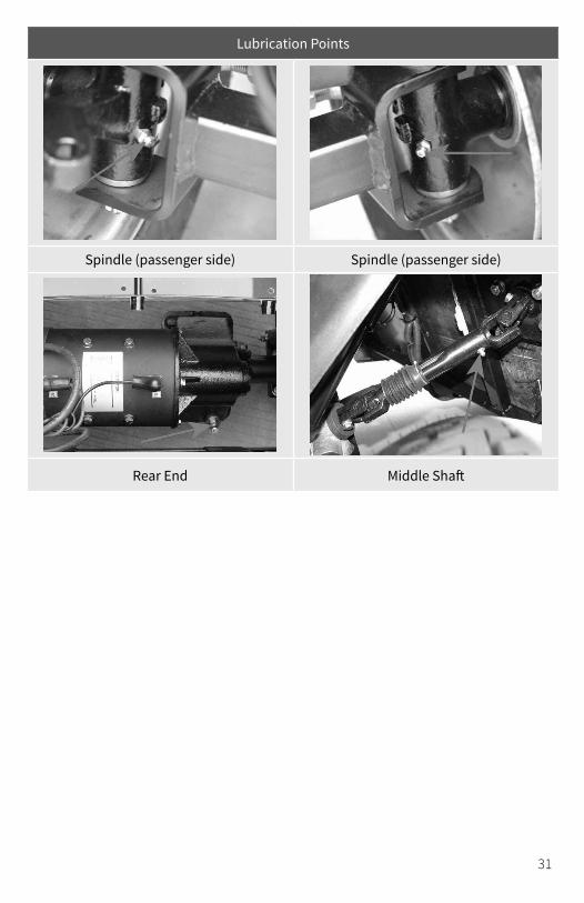
Lubrication
Use 1 liter of 90GL hypoid gear oil for the rear end. Lubrication points: a. Spindle assembly (driver side and passenger side); b. Middle shaft; c. Rear end.
30
31
Lubrication Points
Spindle (passenger side) Spindle (passenger side)
Rear End Middle Shaft

32
8: Troubleshooting
9: Periodic Maintenance Chart
Regular maintenance is required for the best performance and safe operation of the vehicle. Make sure to turn off the power key and apply the parking brake when you do maintenance unless otherwise specified. If the owner is not familiar with the maintenance of this vehicle, this work should be done by a dealer.
Symptoms Possible Causes Troubleshooting
The axle housing gear and bearing are dam-aged and noisy.
The gear oil is insufficient or used improperly. Oil gear or replace.
The bearing is assembled incorrectly. Assemble correctly.
Adjust the brake shoe pin shim or the interval. Adjust or replace.
The gear between axle 1 and 2 is not tightly connected. Adjust correctly.
The final drive is too noisy. Replace the gear.
Axle 1 grinding gears. Adjust or replace.
The rear axle is bent (check if it is over-loaded). Replace the rear axle.
Lack of breaking force
There is space between the brake shoes and drum. Adjust.
There is oily dirt on the brake shoes or drum. Remove dirt.
There is air in the brake pipe. Dispel the air.
The brake pipe leaks. Repair the leakage or replace.
The brake shoes worn. Replace.
The brake cable is too long or is blocked. Adjust the brake cable.
The brake is difficult to release completely.
The brake pedal cannot bounce back smoothly. Replace a new one.
The brake shoe is warped or broken. Refit or replace.
There is blockage on the transmission Refit or replace.
The oil leaksThe oil seal is damaged. Replace.
Too much oil. Adjust the oil level.

33
Item Description Daily Weekly Monthly Quarterly Annually
Battery
Check the liquid level. Add distilled water if necessary. ☑
Charge the battery. ☑
Tighten the nut on the battery cable. ☑
Check if the battery is over-discharged (the battery power meter is flashing). ☑
Check the liquid density of the battery, standard density should be 1.277±0.007g/ cm³ (80˚F or 25˚C) when the battery is fully charged.
☑
Check if the battery is charged fully by a) using the hydrometer, or b) checking the battery power meter.
☑
Clean the surface of battery. ☑
Charger
Observe the charging status; check if the charger plug becomes hot. ☑
Clean the surface of the charger. Do not get any water inside the charger. ☑
Controller
Check that all terminals are tightened proper-ly. Do this after the power is off. ☑
Clean the surface of the controller. ☑
Check that the solenoid is in order by check-ing its touching point. ☑
Motor
Ensure that no water gets in and that it does not become too hot. ☑
Check if the carbon brush should be replaced. ☑
Check that the accelerator pedal works well and that it can be released freely and auto-matically.
☑
Chassis and body
Check if the brake drum and the brake shoe should be replaced. ☑
Check that the hand brake functions (applica-ble for vehicle with hand brake). ☑
Check if the hose and tube for the brake liquid leak (hydraulic brake). ☑
Check if the brake liquid inside the brake liquid tank is sufficient (hydraulic brake). ☑
Check the air pressure inside the tire, check if the tire surface is worn, and check that the nuts are tightened properly.
☑
Check if the shock absorber has any oil leak-ing, or emits an abnormal noise. ☑
Check if there is oil leaking on the gear box and the rear end. ☑
Add lubricant inside the wheel hub and steering system. ☑
Adjust the toe-in of the front end. ☑
Clean the body and seat. ☑

34
10: Storage
Follow the steps as below when the vehicle is stored. 1. Check the liquid level inside the battery; recharge it fully before storing the
vehicle. WARNING: Charge the battery once a month if your vehicle will be stored more than one month.
2. Turn the power key to OFF, remove the key, and store the key in a safe place.
3. Move the tow switch into TOW position on the controller cover.4. Check the tire pressure to make sure its pressure is set to the recommended
amount.5. Clean the exterior of the vehicle and apply rust inhibitor. 6. Cover the vehicle with a breathable cover and store it in a dry, safe and
well-ventilated place.7. If the vehicle is planned to store for a long time, check the liquid level inside
the battery once a month, and recharge the battery.
This manual tries to be as sound and elaborate as possible in literal and figura-tive description as well as technical description on the basis of existing data. At the same time, JH Global reserves the right to alter the content of this manual and this manual is subject to change without prior notice; in addition, JH Global has the final say on the interpretation of this manual.
All rights reserved.

STAR EV, a brand of JH Global Services, Inc.378 Neely Ferry Road | Simpsonville, SC 29680
www.starev.com