Embed Size (px)
Citation preview

OWNER’S MANUAL
6001C
MANUFACTURER
VIBORG HOVEDVEJ 24
DK – 7100 VEJLE, DENMARK
Tel.: +45 75 85 11 82 Fax: +45 75 85 17 82
web: www.uniprolaptimer.com e-mail: [email protected]
Laptimer 6001C 2
Congratulations on your new Laptimer 6001C Please read before use to gain maximum benefit from you new Laptimer Contents
1. Installation page 3
2. SETUP functions page 5
3. Operating the Laptimer before driving/
description of the set-up functions page 6
4. Display functions when driving page 9
5. Operating the Laptimer after driving page 10
6. Memory/deletion of data page 11
7. Battery change page 11
8. Maintenance page 12
9. Printing out data page 12
10. Transfer of data to a PC page 13
11. Troubleshooting page 14
Laptimer 6001C 3
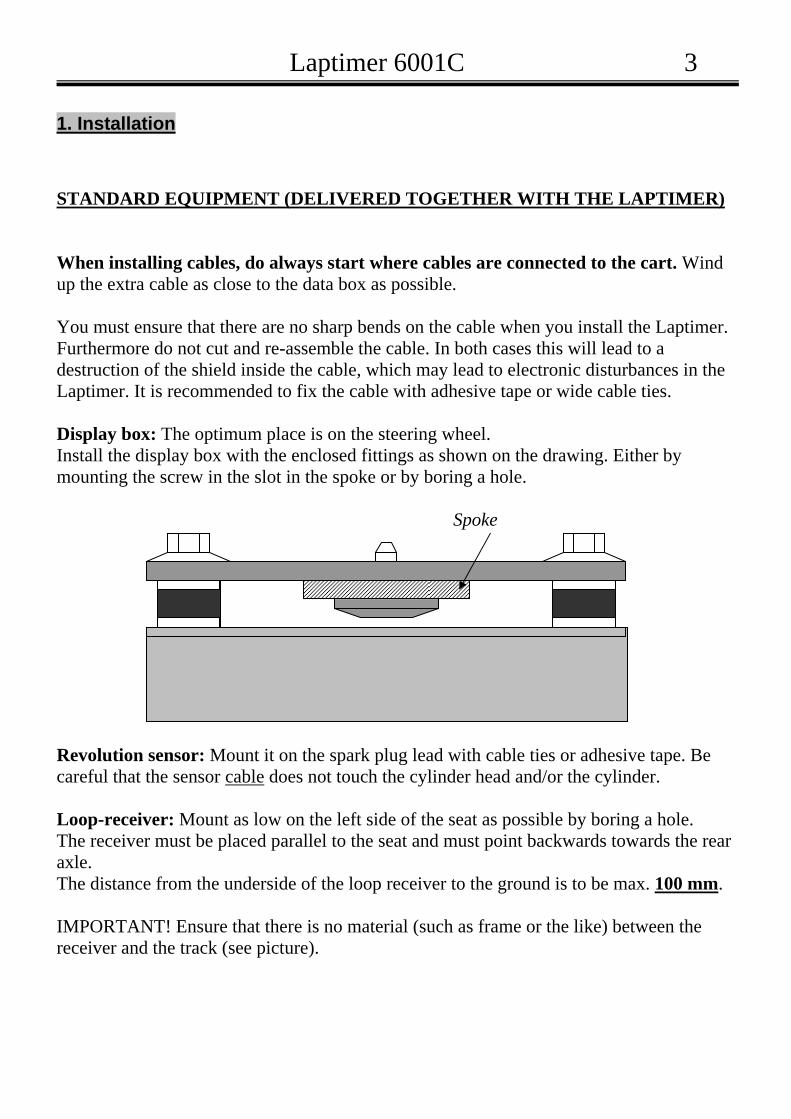
1. Installation STANDARD EQUIPMENT (DELIVERED TOGETHER WITH THE LAPTIMER) When installing cables, do always start where cables are connected to the cart. Wind up the extra cable as close to the data box as possible. You must ensure that there are no sharp bends on the cable when you install the Laptimer. Furthermore do not cut and re-assemble the cable. In both cases this will lead to a destruction of the shield inside the cable, which may lead to electronic disturbances in the Laptimer. It is recommended to fix the cable with adhesive tape or wide cable ties. Display box: The optimum place is on the steering wheel. Install the display box with the enclosed fittings as shown on the drawing. Either by mounting the screw in the slot in the spoke or by boring a hole. Spoke Revolution sensor: Mount it on the spark plug lead with cable ties or adhesive tape. Be careful that the sensor cable does not touch the cylinder head and/or the cylinder. Loop-receiver: Mount as low on the left side of the seat as possible by boring a hole. The receiver must be placed parallel to the seat and must point backwards towards the rear axle. The distance from the underside of the loop receiver to the ground is to be max. 100 mm. IMPORTANT! Ensure that there is no material (such as frame or the like) between the receiver and the track (see picture).

Laptimer 6001C 4
Temperature sensor (water): Mount the sensor in the cylinder head (M10x1). Alternatively on the cooling coil by a T-piece (additional equipment). Wheel sensor (measuring of speed/split times): Sensor disc: To be mounted on the front wheel which is loaded the most. Take off the front wheel in question. Place the centering bush in the inner ring of the front wheel bearing. Place the sensor disc over the sleeve and tighten it. Remove the centering bush and remount the front wheel. The wheel sensor: To be mounted on the steering knuckle. IT IS IMPORTANT that the distance between the sensor disc (on the wheel) and the wheel sensor is between 5–8 mm. ADDITIONAL EQUPMENT IR receiver: To be mounted under the front coat with strips or screws. Mount it on the left side of the cart in a horizontal position. The lens should be between 200 mm and 500 mm above the ground level. On the IR receiver there are connection options either for loop receiver or for magnetic receiver. You can therefore use two receiver types at the same time (IR and loop or IR and magnetic). Magnetic receiver: Mount the magnetic receiver parallel to the bottom plate at the point, which is closest to the ground. The distance between receiver and the ground must not exceed 50 mm.
Laptimer 6001C 5
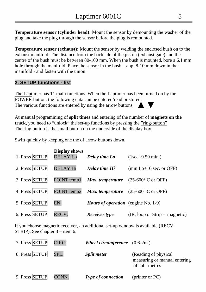
Temperature sensor (cylinder head): Mount the sensor by demounting the washer of the plug and take the plug through the sensor before the plug is remounted. Temperature sensor (exhaust): Mount the sensor by welding the enclosed bush on to the exhaust manifold. The distance from the backside of the piston (exhaust gate) and the centre of the bush must be between 80-100 mm. When the bush is mounted, bore a 6.1 mm hole through the manifold. Place the sensor in the bush – app. 8-10 mm down in the manifold - and fasten with the union. 2. SETUP functions - list The Laptimer has 11 main functions. When the Laptimer has been turned on by the POWER button, the following data can be entered/read or stored. The various functions are entered by using the arrow buttons At manual programming of split times and entering of the number of magnets on the track, you need to “unlock” the set-up functions by pressing the ”ring-button” The ring button is the small button on the underside of the display box. Swift quickly by keeping one the of arrow buttons down. Display shows 1. Press SETUP DELAY Lo Delay time Lo (1sec.-9.59 min.) 2. Press SETUP DELAY Hi Delay time Hi (min Lo+10 sec. or OFF) 3. Press SETUP POINT temp1 Max. temperature (25-600° C or OFF) 4. Press SETUP POINT temp2 Max. temperature (25-600° C or OFF) 5. Press SETUP EN. Hours of operation (engine No. 1-9) 6. Press SETUP RECV. Receiver type (IR, loop or Strip = magnetic) If you choose magnetic receiver, an additional set-up window is available (RECV. STRIP). See chapter 3 – item 6. 7. Press SETUP CIRC. Wheel circumference (0.6-2m ) 8. Press SETUP SPL. Split meter (Reading of physical measuring or manual entering of split metres 9. Press SETUP CONN. Type of connection (printer or PC)

Laptimer 6001C 6
10. Press SETUP TEMP INPUT Connection of temperature inputs (NONE, 1, 2,or 1+2) 11. Press SETUP 2 STRO Type of engine (2 or 4 stroke) When data are entered they are ALWAYS stored when you exit the set-up function by the MODE button or by turning off by the POWER button or the display turns off automatically (after 5 minutes’ of torpor). BE AWARE that the display is turned off automatically after 5 minutes if there has been no register of lap times, RPM or no button has been activated. This may have effect if e.g. a start is delayed. 3. Operation before driving / description of the set-up functions Before you start you must set the delay time Lo and Hi, max. temperature, engine number, receiver type, wheel circumference and type of engine. Turn the Laptimer on by pressing the POWER button. 1. Delay time Lo: (applicable only if you use an IR receiver) Delay time Lo is the minimum time between two signals to the receiver. Setting the delay time is primarily important on tracks where more than one transmitter is placed, or on tracks where the transmitter and the receiver can “see” each other more than once during a lap. (On delivery the Laptimer’s delay time is set to 1 sec.). In order to avoid incorrect signals, you must set the delay time at approx. 2 sec. below the approx. time that a lap takes. Example: If the approx. time for a lap is 40 sec., set the delay time at 38 sec. Prees the SETUP button once and DELAY Lo appears in the display. Set the delay time by using the arrow buttons. Go to the next set-up function by pressing the SETUP button or leave (and store) the entered data by pressing the MODE button. 2. Delay time Hi: Delay time Hi is an extra delay time. If you set this time you avoid to include measurements from laps that takes extra long time due to e.g. a pit stop. By using this facility only “true” laps are stored. Press the SETUP button until DELAY Hi is shown in the display. Set the time by using the arrow buttons. If you are not interested in using the delay time HI, choose DELAY HI OFF. PLEASE NOTE, that the delay time HI is automatically set to minimum the set delay time LO + 10 sec. It is not possible to set a lower delay time HI.

Laptimer 6001C 7
Go to the next set-up function by pressing the SETUP button or leave (and store) the entered data by pressing the MODE button. 3/4. Temperature: By this function you can set the desired max. temperature for both temperature input 1 and 2. When driving the Lap number will flash when the entered temperature is reached. Press the SETUP button until TEMP POINT1 or TEMP POINT2 is shown in the display. Set the desired max. temperature by using the arrow buttons. If you do not want any warning in the display regarding temperature, choose TEMP POINT OFF. Remember to connect the desired temperature input/inputs. See chapter 3 item 10 (connection of temperature inputs). Go to the next set-up function by pressing the SETUP button or leave (and store) the entered data by pressing the MODE button. 5. Hours of operation: By this function you can follow up to 9 engines’ total hours of operation. Hours of operation are measured as the time where signals have been received from the revolution sensor. The measured time is stored when you turn off the Laptimer by the POWER button or the display turns itself off (after 5 minutes’ torpor). Enter the desired engine number by pressing the SETUP button until EN. 1 appears in the display. Choose engine number 1 to 9 by using the arrow buttons. Go to the next set-up function by pressing the SETUP button or leave (and store) the entered data by pressing the MODE button. Choosing the actual engine number in the display and then press the black ring-button can zero the time for each engine. 6. Receiver type: Press the SETUP button until RECV. is shown in the display. Set the desired receiver type (IR, Loop or Strip (magnetic)) by using the arrow buttons. If magnetic receiver is chosen (display shows RECV STRIP ) an additional window is automatically available. The number of magnets on the track is to be entered here as well as the number of magnets, if any, between the pit exit and the finishing line. It is important that the Laptimer always trigs on the stripe that defines the finishing line. You have now chosen magnetic receiver and the display shows RECV STRIP. Then press the SETUP button once until e.g. STRIPE 0-1 is shown. Then press the ring-button to “unlock” the function. The display shows e.g. STRIPES 1 (the number flashes). Enter the number of magnetic stripes on the track by using the arrow buttons. Press the ring-button again. The display shows e.g. DELAY NO 0

Laptimer 6001C 8
Enter the number of magnetic stripes on the track between the pit exit and the finishing line by using the arrow buttons. Press the ring-button again. The display now shows e.g. STRIPE 1-3 meaning that there are 3 stripes on the track and 1 stripe between the pit exit and the finishing line. Go to the next set-up function by pressing the SETUP button or leave (and store) the entered data by pressing the MODE button. 7.Wheel circumference. Press the SETUP button until CIRC appears in the display. Measure the circumference (in mm) on the wheel on which the sensor disc is mounted. Enter the measurement by using the arrow buttons. Go to the next set-up function by pressing the SETUP button or leave (and store) the entered data by pressing the MODE button. The wheel circumference must be checked after every heat/test session and if the tyre pressure has been changed. Enter new measurement, if any. This is important to ensure that you get correct information on each lap. 8. Split meters: Physical measuring of the track – prior to driving on a new track Turn the Laptimer on. Press the SPL button and keep it down until CLEAR SPLS appears in the display. (Be aware that stored lap times/split times are deleted when you use this function). Before entering the track, you should check that the wheel sensor scans 6 times per revolution of the wheel, i.e the crystal in the SPL window must move 6 times per revolution of the wheel. When you enter the track and pass the transmitter for the first time, a 0 appears in the SPL window and the measuring is commenced. When you reach the spot on the track where you want a split time, pressing the ring-button under the display box sets a mark. Repeat this until you have entered all the marks you want. Maximum is 8 marks = 9 split times. (The last split time is the time between the last mark and the zero point = the finishing line (the transmitter, the loop or the magnetic stripe)). When the transmitter is passed again the measuring is stored and the Laptimer now starts to show lap times etc. The measuring is retained in the memory of the Laptimer until you enter a new measuring (either by physical measuring as described above or by manual entering of track measuring as described below). Manual entering of track measuring This option is valuable if you drive on a known track and wish to measure the same split times again. You can only do this if you have noted the necessary data or if you have had the data printed out or stored the data on a PC.
Laptimer 6001C 9
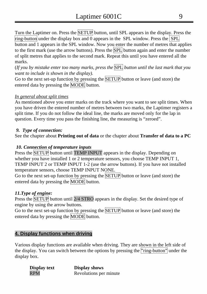
Turn the Laptimer on. Press the SETUP button, until SPL appears in the display. Press the ring-button under the display box and 0 appears in the SPL window. Press the SPL button and 1 appears in the SPL window. Now you enter the number of metres that applies to the first mark (use the arrow buttons). Press the SPL button again and enter the number of split metres that applies to the second mark. Repeat this until you have entered all the marks. (If you by mistake enter too many marks, press the SPL button until the last mark that you want to include is shown in the display). Go to the next set-up function by pressing the SETUP button or leave (and store) the entered data by pressing the MODE button. In general about split times As mentioned above you enter marks on the track where you want to see split times. When you have driven the entered number of metres between two marks, the Laptimer registers a split time. If you do not follow the ideal line, the marks are moved only for the lap in question. Every time you pass the finishing line, the measuring is “zeroed”. 9. Type of connection:
See the chapter about Printing out of data or the chapter about Transfer of data to a PC 10. Connection of temperature inputs
Press the SETUP button until TEMP INPUT appears in the display. Depending on whether you have installed 1 or 2 temperature sensors, you choose TEMP INPUT 1, TEMP INPUT 2 or TEMP INPUT 1-2 (use the arrow buttons). If you have not installed temperature sensors, choose TEMP INPUT NONE. Go to the next set-up function by pressing the SETUP button or leave (and store) the entered data by pressing the MODE button. 11.Type of engine: Press the SETUP button until 2/4 STRO appears in the display. Set the desired type of engine by using the arrow buttons. Go to the next set-up function by pressing the SETUP button or leave (and store) the entered data by pressing the MODE button. 4. Display functions when driving Various display functions are available when driving. They are shown in the left side of the display. You can switch between the options by pressing the ”ring-button” under the display box.
Display text Display shows RPM Revolutions per minute

Laptimer 6001C 10
Nothing Speed in km/h * TEMP Temperature input 1 in °C (”TEMP” shows constantly in
the display) * TEMP Temperature input 2 in °C (”TEMP” flashes in the display) * Only if temperature inputs are connected in SETUP. See chapter 3 item 10
The following data are shown currently during the driving
Display text Display shows LAP Number of laps LAP TIME Actual lap time BEST LAP TIME Is shown if the actual lap time is the best lap time so far
5. Operating after driving After the race/test you can go through all stored data. Press the MODE button (the Laptimer is now in pitmode) and the stored lap times are shown (with the arrow buttons you can flip through the lap times). For each lap the following data are furthermore available. Shift between the options by pressing the ”ring-button” under the display box.
Display text Display shows RPM Lo Lowest revolutions RPM Hi Highest revolutions Lo Lowest speed Hi Highest speed *TEMP 1 Lo Lowest temperature at input 1 *TEMP 1 Hi Highest temperature at input 1 *TEMP 2 Lo Lowest temperature at input 2 (”TEMP” flashes) *TEMP 2 Hi Highest temperature at input 2 (”TEMP” flashes)

Laptimer 6001C 11
* Only if temperature inputs are connected in SETUP. See chapter 3 item 10.
Split-times: You can furthermore see your split times per lap by pressing the SPL button. (The Laptimer must be in pitmode). Flip through the split times of the lap by pressing the SPL button. If you wish to see RPM, speed or TEMP (see above) for each split time, press the ”ring-button” under the display box. If you wish to see RPM, speed or TEMP for the same split time in all laps, use the arrow button. The split times are numbered from 1-8 (depending on the number of marks that has been entered). The last split time is called L (last) = split time from the last mark to the zero point = finishing line (the transmitter, the loop or the magnetic stripe). When you have finished going through your lap times etc., you turn the Laptimer off by pressing the POWER button or the Laptimer will turn itself off after 5 minutes (see chapter 2). When you turn your Laptimer on next time, it will automatically show the last lap stored. The Laptimer is ready to receive further signals from the transmitter. 6. The memory of the Laptimer / deletion of data The Laptimer has a memory capacity of up to 1,000 laps! Stored data can be deleted in the following way. The Laptimer must be on. Press the POWER button until CLEAR LAPS appears in the display. All stored set-up functions are NOT deleted by above action 7. Battery change Two 1.5V batteries size AA are required (must be alcaline batteries). (Duracell batteries are recommended). Battery life is 20-40 hours depending on battery type/product. When you want to change batteries, loosen all cables. Remove the sheet at the back of the main box. Change batteries. Important: When replacing the sheet at the back of the main box be sure it is placed correctly. Check that the mark in the rubber seal turns the right way.

Laptimer 6001C 12
The Laptimer has indicators to show low power: • When the battery symbol appears in the display, it indicates low power (does not
appear before the Laptimer bas been on for more than 10 sec.) . • When the symbol starts flashing, app. 10 minutes of operation remains. • When the complete display flashes, only 5 minutes of operation remains.
Stored data are not lost at battery change! 8. Maintenance The Laptimer can be used in all weathers. However, if you have been driving in rainy weather, the Laptimer should be dismantled after driving. Remove the back plate of the display box and place all parts in a warm place for 24 hours. Then all parts can be re-assembled and re-installed. Do not seal with liquid packing or with any other kind of sealing compound. 9. Printing out of data In order to print out the stored data, you need a Seiko DPU 414 or the like with printer cable (is available at your dealer). Connect the printer cable to the printer and the Laptimer (at the under side) and turn the Laptimer on. Choose CONN PRINT in the set-up menu. Leave (and store) the entered data by pressing the MODE button. Press the POWER button (if the Laptimer is not already on). Press the MODE button twice and the Laptimer is now in PRINTMODE. The order of options at the first printout:
PR. SETUP You get a printout where you can enter the set-up of the cart, status of hours of operation and wheel circumference PRINT ALL All data exclusive of split data are printed out PR SPLITS All split times are printed out
Laptimer 6001C 13
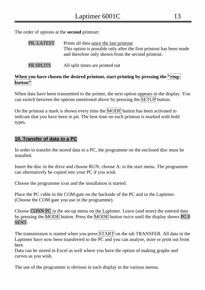
The order of options at the second printout: PR. LATEST Prints all data since the last printout This option is possible only after the first printout has been made and therefore only shown from the second printout. PR SPLITS All split times are printed out
When you have chosen the desired printout, start printing by pressing the ”ring-button” When data have been transmitted to the printer, the next option appears in the display. You can switch between the options mentioned above by pressing the SETUP button. On the printout a mark is shown every time the MODE button has been activated to indicate that you have been in pit. The best time on each printout is marked with bold types. 10. Transfer of data to a PC In order to transfer the stored data to a PC, the programme on the enclosed disc must be installed. Insert the disc in the drive and choose RUN, choose A: in the start menu. The programme can alternatively be copied into your PC if you wish. Choose the programme icon and the installation is started. Place the PC cable in the COM gate on the backside of the PC and in the Laptimer. (Choose the COM gate you use in the programme). Choose CONN PC in the set-up menu on the Laptimer. Leave (and store) the entered data by pressing the MODE button. Press the MODE button twice until the display shows PC 0 SENT. The transmission is started when you press START on the tab TRANSFER. All data in the Laptimer have now been transferred to the PC and you can analyse, store or print out from here. Data can be stored in Excel as well where you have the option of making graphs and curves as you wish. The use of the programme is obvious in each display in the various menus.

Laptimer 6001C 14
11. Troubleshooting The Laptimer is switched on but does not register lap times, check the following:
• Is the IR/loop transmitter switched on? • Is the IR/loop receiver placed horizontally and at the correct height? • Have you chosen the right RECV. in SETUP ? • Is the magnetic receiver placed parallel to the cart? • Is the distance between the transmitter and the receiver correct (should be between
2-3 metres)? • Is the battery power sufficient? • Does the Laptimer not receive a signal every time the transmitter/loop is passed?
Check if the delay time is set too high. The Lo-delay function cannot be used if you have chosen RECV. STRIPE in SETUP
The Laptimer does not register correct split times/speed:
• Check if the distance between the wheel sensor and the sensor disc is correct (5-8 mm).
Printing out is not successful
• Press the SETUP button and check that CONN PRINT has been chosen. • Check that the cable is correctly connected.
Transfer to a PC does not work:
• Check by pressing the SETUP button that CONN PC has been chosen. • Check that the cable is correctly connected.
You are stuck and are not sure where in the programme you are:
• Press the POWER button and turn the Laptimer off. Turn it on again by pressing the POWER button and the Laptimer is back in “driving-mode”.
Error in indication of revolutions: • Due to big differences between the different ignition products, it may be necessary to
install another type of revolution sensor than the standard one – this applies for e.g. Formula Yamaha. Contact your dealer.