Embed Size (px)
Citation preview

Owner’s Information Manual
A170030Fig. 1 – Unit PGD4, PGS4, WPG4
Our products are designed, tested and built in accordance with DOE standardized procedures; however, actual operating results and efficiencies mayvary based on manufacturing and supplier tolerances, equipment configuration, operating conditions and installation practices.
PGD4, PGS4, WPG414 SEER Single and Three Phase Single Packaged Air Conditioner and Gas FurnaceSystem With R-410A Refrigerant2-5 Nominal Tons (Sizes 24-60)
Technician Name
Phone Number
Address
Company Name
Date Installed
NOTE TO EQUIPMENT OWNER:
For your convience, please record the model and serial numbers of your new equipment in the spaces
provided. This information, along with the installation data and dealer contact information, will be
helpful should your system require maintenance or service.
UNIT INFORMATION
ACCESSORIES (List type of model #)
INSTALLATION INFORMATION
DEALERSHIP CONTACT INFORMATION
This manual must be left with the eqipment owner.
NOTE TO INSTALLER:
Model #
Serial #

PGD4, PGS4, WPG4: Owner’s Information Manual
Manufacturer reserves the right to change, at any time, specifications and designs without notice and without obligations.2
Safety ConsiderationsImproper installation, adjustment, alteration, service maintenance, or usecan cause explosion, fire, electrical shock, or other conditions whichmay cause death, personal injury, or property damage. Consult aqualified installer, service agency, or your distributor or branch forinformation or assistance. The qualified installer or agency must usefactory-authorized kits or accessories when modifying this product.Refer to the individual instructions packaged with the kits or accessorieswhen installing.Follow all safety codes. Wear safety glasses, protective clothing, andwork gloves. Have a fire extinguisher available. Read these instructionsthoroughly and follow all warnings or cautions included in literature andattached to the unit. consult local building codes, the current editions ofthe National Fuel Gas Code (NFGC) NFPA 54/ANSI Z223.1, and theNational Electrical Code (NEC) NFPA 70.In Canada refer to the current editions of the National Standards ofCanada CAN/CSA-B149.1 and .2 Natural Gas and Propane Installationcodes, and Canadian Electrical Code CSA C22.1
Recognize safety information. This is the safety-alert symbol . Whenyou see this symbol on the unit and in instructions or manuals, be alert tothe potential for personal injury. Understand these signal words:DANGER, WARNING, and CAUTION. These words are used with thesafety-alert symbol. DANGER identifies the most serious hazards whichwill result in severe personal injury or death. WARNING signifieshazards which could result in personal injury or death. CAUTION isused to identify unsafe practices which may result in minor personalinjury or product and property damage. NOTE is used to highlightsuggestions which will result in enhanced installation, reliability, oroperation.NOTE: Installer: This manual should be left with the equipment user.
Most states is the USA and jurisdictions in Canada have laws thatrequire the use of Carbon Monoxide (CO) alarms with fuel burningproducts. Examples of fuel burning products are furnaces, boilers, spaceheaters, generators, water heaters, stoves/ranges, clothes dryers,fireplaces, incinerators, automobiles, and other internal combustionengines. Even if there are no laws in your jurisdiction requiring a COAlarm, it’s highly recommended that whenever any fuel burning productis used in or around the home or business that the dwelling be equippedwith a CO Alarm(s). The Consumer Product Safety Commissionrecommends the use of CO Alarm(s). The CO Alarm(s) must beinstalled, operated, and maintained according to the CO Alarmmanufacturer’s instructions. For more information about CarbonMonoxide, local laws, or to purchase a CO Alarm, please visit thefollowing website https://www.kidde.com
WARNING!CARBON MONOXIDE POISONING HAZARDFailure to follow this warning could result in personal injury and/ordeath.Carbon Monoxide (CO) is a colorless, odorless, and tasteless poisonousgas that can be fatal when inhaled. Follow all installation, maintenance,and service instructions. See additional information below regardingthe installation of a CO Alarm.
WARNING!FIRE, EXPLOSION, ELECTRICAL SHOCK HAZARDFailure to follow this warning could result in personal injury, death orproperty damage.Installation and servicing of this equipment can be hazardous due tomechanical and electrical components. Only trained and qualifiedpersonnel should install, repair, or service this equipment.
WARNING!FIRE, EXPLOSION HAZARDFailure to follow this warning could result in personal injury, death,and/or property damage.Do not store or use combustible materials, gasoline, or other flammablevapors and liquids in the vicinity of this or any other appliance.
WARNING!FIRE, EXPLOSION, ELECTRICAL SHOCK HAZARDFailure to follow this warning could result in personal injury, death orproperty damage.Do not use this unit if any part has been under water. Immediately call aqualified service technician to inspect the unit and to replace any part ofthe control system which has been under water.
WARNING!FIRE AND EXPLOSION HAZARDFailure to follow safety warning exactly could result in serious injury,death or property damage.Do not store or use gasoline or other flammable vapors and liquids inthe vicinity of this or any other appliance. WHAT TO DO IF YOU SMELL GAS
- Do not try to light any appliance.- Do not touch any electrical switch; do not use any phone in your
building.- Leave the building immediately.- Immediately call your gas supplier from a neighbor’s phone.
Follow the gas supplier’s instructions.- If you cannot reach your gas supplier, call the fire department.
Installation and service must be performed by a qualified installer,service agency or the gas supplier.
WARNING!ELECTRICAL SHOCK HAZARDFailure to follow this warning could result in personal injury and/ordeath.Before performing recommended maintenance, be sure the main powerswitch to unit is turned off and lock-out tag is installed. There may bemore than one disconnect switch.

PGD4, PGS4, WPG4: Owner’s Information Manual
Manufacturer reserves the right to change, at any time, specifications and designs without notice and without obligations.3
Unit IntroductionThis unit is a small packaged gas heat/electric cooling system that canutilize the comfort of gas heating packaged along with efficient electricair conditioning. This unit uses R-410A, the environmentally balancedrefrigerant for cooling. Starting or Shutting Off UnitNOTE: Your combination heating/cooling unit is equipped with anautomatic direct spark ignition and power combustion blower.To start unit gas heat:Refer to Fig. 2 for location of unit front access panel. Refer to Fig. 3 forlocation of gas valve. Refer to Fig. 4 while proceeding with thefollowing steps.1. Set the temperature selector on room thermostat to the lowest
temperature setting and set system switch to HEAT.2. Close the external manual gas shutoff valve.3. Turn off the electrical supply to the unit.4. Remove the control access panel with a 5/16-in. nut driver. (See
Fig. 2.)
A170032Fig. 2 – Unit Access Panel
5. Move the selector switch on the internal gas valve to the OFFposition and wait 5 minutes.
6. Move the selector switch on the internal gas valve to the ONposition.
7. Replace the control access panel.8. Turn on the electrical supply to unit.9. Open the external manual gas shutoff valve.10. Set the temperature selector on room thermostat slightly above
room temperature to start unit. The induced-draft combustion airfan will start. Main gas valve will open and main burners shouldignite within 5 seconds. If the burner does not light within 5seconds, the ignition module will go into a Retry Mode after aperiod of approximately 22 seconds (following the 5-secondignition period). If the burners do not light within 15 minutes of theinitial call for heat, there is a lockout.
11. Set the temperature selector on room thermostat to desired setting.
WARNING!FIRE, EXPLOSION, ELECTRICAL SHOCK HAZARDFailure to follow this warning could result in personal injury, deathand/or property damage.1. Do not turn off the electrical power to unit without first turning offthe gas supply.2. Before attempting to start the gas heating section, familiarizeyourself with all the procedures that must be followed.
WARNING!FIRE, EXPLOSION HAZARDFailure to follow this warning could result in personal injury, death,and/or property damage.Do not attempt to light by hand.
CAUTION!CUT HAZARDFailure to follow this caution may result in personal injury. When removing access panels or performing maintenance functionsinside your unit, be aware of sharp sheet metal parts and screws.Although special care is taken to reduce sharp edges to a minimum, beextremely careful and wear safety glasses, protective clothing, andwork gloves when handling parts or reaching into the unit.
WARNING!FIRE AND EXPLOSION HAZARDFailure to follow this warning could result in personal injury, death,and/or property damage.
1. If the main burners fail to light, or the blower fails to start, shutdown gas heating section and call your dealer for service.
2. Never attempt to manually light the main burners on unit with amatch, lighter, or any other flame. If the electric sparking devicefails to light the main burners, refer to the following shutdownprocedures, then call your dealer as soon as possible.
COMPRESSOR ACCESS PANEL
BLOWERACCESSPANEL
CONTROLACCESSPANEL
PGD4, PGS4, WPG4: Owner’s Information Manual
Manufacturer reserves the right to change, at any time, specifications and designs without notice and without obligations.4
Fig. 3 – Gas Heating/Electric Cooling Unit with Access Panel Removed
To shut off unit gas heat:
NOTE: If the unit is being shut down because of a malfunction, callyour dealer as soon as possible.Should overheating occur or the gas supply fail to shut off, shut off theexternal manual gas valve to the unit before shutting off the electricalsupply. Do not use this unit if any part has been under water.Immediately call a qualified service technician to inspect the unit and toreplace any part of the control system and any gas control which hasbeen under water.Refer to Fig. 5 while proceeding with the following steps.1. Set the temperature selector on room thermostat to lowest
temperature setting and set system SWITCH to OFF.2. Close the external manual shutoff valve.3. Turn off the electrical power supply to the unit.4. Remove the control access panel. (See Fig. 2.)5. Move the selector switch on the internal gas valve to the OFF
position.6. Replace the control access panel.
To start unit electric cooling:Refer to Fig. 6 while proceeding with the following steps.1. Set the temperature selector on room thermostat to highest
temperature setting and set system SWITCH to OFF.2. Close the external manual shutoff valve, if not already closed.3. Turn ON the electrical power supply to the unit.4. Set system switch to COOL.5. Set the temperature selector on room thermostat slightly below the
room temperature to start unit.To shut off unit electric cooling:Refer to Fig. 7 while proceeding with the following steps.1. Set the temperature selector on room thermostat to highest
temperature setting and set system SWITCH to OFF.2. Close the external manual shutoff valve, if not already closed. 3. Turn off the electrical power supply to the unit.
Operating Your UnitThe operation of your unit is controlled by the indoor temperaturecontrol (thermostat). You simply adjust the thermostat and it maintainsthe indoor temperature at the level you select. Most thermostats ofheating and cooling systems have 3 controls: a temperature controlselector, a FAN control, and a SYSTEM or MODE control. Refer to yourthermostat owner’s manual for more information.To better protect your investment and to eliminate unnecessary servicecalls, familiarize yourself with the following facts:Cooling ModeWith the SYSTEM control set to COOL, your unit will run in coolingmode until the indoor temperature is lowered to the level you haveselected. On extremely hot days, your unit will run for longer periods ata time and have shorter “off” periods than on moderate days.Gas Heat ModeWith the SYSTEM or MODE control of your indoor thermostat set toHEAT, your unit will run in heating mode until room temperature israised to the level you have selected. On cold days and nights, yoursystem will typically run for longer periods of time and have shorter“off” periods than on moderate days.
Maintenance and ServiceThis section discusses maintenance that should be performed on yoursystem. Most maintenance should be performed by your dealer. You, asthe owner, may wish to handle some minor maintenance for your newunit.Routine MaintenanceAll routine maintenance should be handled by skilled, experiencedpersonnel. Your dealer can help you establish a standard procedure.For your safety, keep the unit area clear and free of combustiblematerials, gasoline, and other flammable liquids and vapors.To assure proper functioning of the unit, flow of condenser air must notbe obstructed from reaching the unit. Clearance from the top of the unitis 48 in. (1219 mm). Clearance of at least 36 in. (914 mm) is required onsides except the power entry side (42 in. [1067 mm] clearance) and theduct side (12 in. [305 mm] minimum clearance). Also, ensure that thereturn-air duct connection (s) is physically sound, is sealed to the furnacecasing, and terminates outside the space containing the furnace.
WARNING!FIRE, EXPLOSION, ELECTRICAL SHOCK HAZARDFailure to follow this warning could result in personal injury, death,and/or property damage.Do not turn off the electrical power to unit without first turning off thegas supply.
Burners Gas Valve
Flue Hood

PGD4, PGS4, WPG4: Owner’s Information Manual
Manufacturer reserves the right to change, at any time, specifications and designs without notice and without obligations.5
A07662Fig. 4 – To Start Unit Gas Heat
55
STEP 1 STEP 2
CLOSE
STEP 3
OFF
ON
MAIN
STEP 4
STEP 7
OFF
ON
MAIN
STEP 8
STEP 5
72
STEP 10
STEP 6
STEP 9
OPEN

PGD4, PGS4, WPG4: Owner’s Information Manual
Manufacturer reserves the right to change, at any time, specifications and designs without notice and without obligations.6
A07663Fig. 5 – To Shut-off Unit Gas Heat
A09194Fig. 6 – To Start Unit Electric Cooling
55
STEP 1 STEP 2
CLOSE
STEP 3
OFF
ON
MAIN
STEP 4
STEP 6
STEP 5
90
STEP 1 STEP 2
CLOSE
72
STEP 4 & 5
OFF
ON
MAIN
STEP 3

PGD4, PGS4, WPG4: Owner’s Information Manual
Manufacturer reserves the right to change, at any time, specifications and designs without notice and without obligations.7
A07797
Fig. 7 – To Shut-off Unit Electric Cooling
Maintenance and Care for the Equipment OwnerBefore performing equipment maintenance yourself, please carefullyconsider the following:
Air FiltersThe air filter(s) should be checked every 3 or 4 weeks and changed orcleaned whenever it becomes dirty. Dirty filters produce excessive stresson the blower motor and can cause the motor to overheat and shut down.This unit must have air filters in place before it can be operated. Thesefilters can be located in one of at least two places. In many applications,the installer will provide return air filter grilles mounted on the wall orceiling of the conditioned structure. In the instance of filter grilles, thefilters can simply be removed from the grille and replaced.The other typical application is an accessory filter rack installed insidethe unit itself. The following information is given to assist in changingfilters used in these internal filter racks.Filter kits are available as a purchased accessory. The same filter kit isincluded with the accessory economizers and factory installedeconomizers. To replace or inspect filters in accessory filter rack (See Fig. 2):1. Remove the filter access panel using a 5/16-in. nut driver.2. Remove the filter(s) by pulling it out of the unit. If the filter(s) is
dirty, clean or replace with a new one.When installing the new filter(s), note the direction of the airflow arrowson the filter frame which should be pointing at the indoor coil.3. Reinstall filter access panel ensuring opening is air and water tight.
If you have difficulty locating your air filter(s) or have questionsconcerning proper filter maintenance, contact your dealer forinstructions. When replacing filters, always use the same size and type of
filter that was supplied originally by the installer. See Table 1 for filtersizes supplied with accessory filter rack.
Replacing or inspecting filters in units with economizersSmall Chassis (See Fig. 8)1. Remove return air duct cover at rear of unit using a 5/16-in. nut
driver.2. Remove the filter(s) by pulling it out and through the unit duct
opening. If filter is dirty, replace both filters with new ones. When installing the new filters, note the direction of the airflow arrowson the filter frame, which should be pointing at the indoor coil.3. Reinstall duct cover ensuring opening is air and watertight.
Large Chassis (See Fig. 9)1. Remove filter access door using a 5/16-in. nut driver.2. Remove the filter(s) by pulling it out and through the unit filter
access door. If filter is dirty, replace both filters with new ones. Units with bent indoor coils, install 24 x 18 x 1 (610 x 457 x 25 mm)filter first and then install 24 x 16 x 1 (610 x 406 x 25) filter.When installing the new filters, note the direction of the airflow arrowson the filter frame, which should be pointing at the indoor coil.3. Reinstall filter access door ensuring opening is air and water tight.
90
STEP 1 STEP 2
CLOSE
STEP 3
OFF
ON
MAIN
WARNING!FIRE, EXPLOSION ELECTRICAL SHOCK AND CUT HAZARDFailure to follow this warning could result in personal injury, death orproperty damage.
1. Turn off gas supply first, then all electrical power to your unitand install lock-out tag before servicing or performingmaintenance.
2. When removing access panels or performing maintenancefunctions inside your unit, be aware of sharp sheet metal partsand screws. Although special care is taken to reduce sharpedges to a minimum, be extremely careful when handling partsor reaching into the unit. Wear safety glasses, gloves andappropriate protective clothing.
Table 1 – Replacement Filter Sizes
Unit Size Filter Size
24-040/060 2 each 20 x 12 x 1(508 x 305 x 25 mm)
30-040/060 2 each 20 x 12 x 1(508 x 305 x 25 mm)
36-060/090 2 each 20 x 12 x 1(508 x 305 x 25 mm)
42-060/090 1 each 24 x 14 x 1 (610 x 356 x 25 mm),24 x 16 x 1 (610 x 406 x 25 mm)
48-090/115/130 1 each 24 x 14 x 1 (610 x 356 x 25 mm),24 x 16 x 1 (610 x 406 x 25 mm)
60-090/115/130*
*. Units with bent indoor coil.
1 each 24 x 16 x 1 (610 x 406 x 25 mm),24 x 18 x 1 (610 x 457 x 25 mm)

PGD4, PGS4, WPG4: Owner’s Information Manual
Manufacturer reserves the right to change, at any time, specifications and designs without notice and without obligations.8
A10063Fig. 8 – Small Chassis Filter Access
A10062Fig. 9 – Large Chassis Filter Access
Fans and Fan MotorsPeriodically check the condition of fan wheels and housings and fanmotor shaft bearings. Contact your dealer for the required annualmaintenance.Heat ExchangerTo ensure dependable and efficient heating operation, the heat exchangershould be checked by a qualified maintenance person before eachheating season, and cleaned when necessary. This checkout should notbe attempted by anyone not having the required expertise and equipmentto properly do the job. Contact your dealer for the required periodicmaintenance.Indoor and Outdoor CoilsCleaning of the coils should only be done by qualified service personnel.Contact your dealer for the required annual maintenance.Condensate DrainThe drain pan and condensate drain line should be checked and cleanedat the same time the cooling coils are checked by your dealer.
CompressorAll compressors are factory shipped with a normal charge of the correcttype of refrigeration grade oil.Condenser (Outdoor) Fan
The fan must be kept free of all obstructions to ensure proper cooling.Contact your dealer for any required service.Electrical Controls and WiringElectrical controls are difficult to check without proper instrumentation.If there are any discrepancies in the operating cycle, contact your localdealer and request service.Refrigerant CircuitThe refrigerant circuit is difficult to check for leaks without the properequipment. If inadequate cooling is suspected, contact your local dealerfor service.
Unit PanelsAfter performing any maintenance or service on the unit, be sure allpanels are fastened securely in place to prevent rain from entering unitcabinet and to prevent disruption of the correct unit airflow pattern.Combustion Area and Vent SystemFor proper and safe operation, the unit needs air for combustion andventilation. The air openings, on the unit, the air openings to the area inwhich the unit is installed, and the spacing around the unit must not beblocked or obstructed.The combustion air inlet area and vent hood should be inspected visuallybefore each heating season. The normal accumulation of dirt, soot, rust,and scale can result in loss of efficiency and improper performance ifallowed to build up. This inspection should be done by a trained serviceperson.
CAUTION!UNIT OPERATION HAZARDFailure to follow this caution may result in property damage.Never operate your unit without filters in place. An accumulation ofdust and lint on internal parts of your unit can cause loss of efficiencyand blower motor and/or compressor damage.
RETURNDUCT COVER(Remove forfilter access)
SMALL CHASSIS
LARGE CHASSIS
FILTERACCESSPANEL
WARNING!PERSONAL INJURY AND UNIT DAMAGE HAZARDFailure to follow this warning could result in personal injury, death orproperty damage.Do not insert sticks, screwdrivers, or any other objects into revolvingfan blades.
WARNING!EXPLOSION AND ENVIRONMENTAL HAZARDFailure to follow this warning could result in personal injury, death orproperty damage.System under pressure. Relieve pressure and recover all refrigerantbefore system repair or final unit disposal. Use all service ports andopen all flow-control devices, including solenoid valves.
WARNING!FIRE, EXPLOSION HAZARDFailure to follow this warning could result in personal injury, deathand/or property damage.If your unit makes an especially loud noise when the main burners areignited, shut down the heating section and call your dealer.

PGD4, PGS4, WPG4: Owner’s Information Manual
Manufacturer reserves the right to change, at any time, specifications and designs without notice and without obligations.9
Regular Dealer Maintenance (Also refer to Table 2)In addition to the type of routine maintenance you might be willing toperform, your unit should be inspected regularly by a properly trainedservice technician. An inspection (preferably each year) should includethe following:1. Inspection of all flue product passages-including the burners, heat
exchanger, and flue collector box, Mare sure the burner flames areblue in color and in proper adjustment. Refer to Fig. 10 for burnerflame.
2. Inspection of all combustion-and ventilation-air passages andopenings.
3. Close inspection of all gas pipes leading to and inside of your unit.4. Inspection and, if required, cleaning of the outdoor and indoor
coils.5. Inspection and, if required, cleaning of the indoor coil condensate
drain pan.
C99021Fig. 10 – Monoport Burner
6. Inspection and cleaning of blower wheel housing and motor.7. Inspection of all supply-air and return-air ducts for leaks,
obstructions, and insulation integrity. Any problems found shouldbe resolved at this time.
8. Inspection of the unit base to ensure that no cracks, gaps, etc., existwhich may cause a hazardous condition.
9. Inspection of the unit casing for signs of deterioration.10. Inspection of all electrical wiring and components to assure proper
connection.11. Inspection for leaks in the refrigerant circuit. Pressure check to
determine appropriate refrigerant charge.12. Operational check of the unit to determine working conditions.
Repair or adjustment should be made at this time.Your servicing dealer may offer an economical service contract thatcovers seasonal inspections. Ask for further details.Complete service instructions can be found in the unit Installation,Start-up and Service Instructions.
Warranty CertificateYour unit has a limited warranty. Be sure to read the warranty carefullyto determine the coverage for your unit.Before you call for service......check for several easily-solved problems.If insufficient heating or cooling is suspected:( ) Check for sufficient airflow. Check the air filter for dirt. Check forblocked return-air or supply-air grilles. Be sure they are open andunobstructed. If these checks do not reveal the cause, call your servicingdealer.If your unit is not operating at all, check the following list for easysolutions:( ) Check to be sure that your thermostat temperature selector is setbelow the indoor temperature during the cooling season or above theindoor temperature during heating season. Be sure the SYSTEM switchor MODE control is in the COOL or HEAT position and not in the OFFposition.( ) If your unit still fails to operate, call your servicing dealer fortroubleshooting and repairs. Specify the model and serial numbers ofyour unit. (Record them in this manual in the space provided.) If thedealer knows exactly which unit you have, he may be able to offersuggestions over the phone, or save valuable time throughknowledgeable preparation for the service call.In Case of TroubleIf you perform the steps above and unit performance is stillunsatisfactory, shut off the unit and call your dealer.
CAUTION!BURN HAZARDFailure to follow this caution may result in personal injury.Components in heating section may be hot after unit has been startedup. When observing flame, be careful not to get close to or touchheating components.
MANIFOLD
BURNER
BURNER FLAME
© 2020 Carrier. All rights reserved.A Carrier Company
Edition Date: 08/20 Catalog No: 462200206Replaces: 462200205
PGD4, PGS4, WPG4: Owner’s Information Manual
Manufacturer reserves the right to change, at any time, specifications and designs without notice and without obligations.10
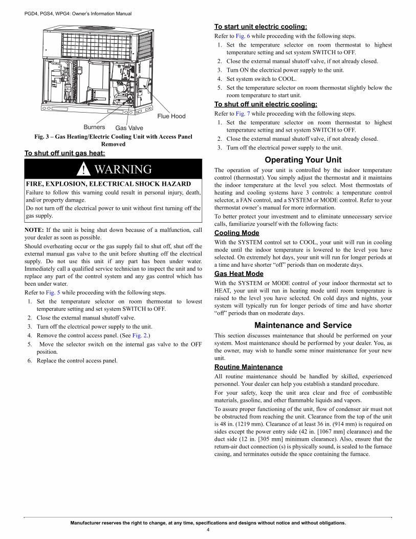
Table 2 – Maintenance ChecklistMonthly maintenance items and outdoor unit rinsing may be performed by the consumer. All other maintenance items and all service work must beperformed by a qualified service technician. Read all Warning labels.
Description of Maintenance Recommended IntervalConsumer specific: Monthly AnnualInspect, clean, or replace air filter if filter is located indoors in return air grill. XClear away debris and vegetation near unit. XDealer specific:Inspect cabinet and basepan for damage. Replace panels, gaskets, and other components that are damaged or severely rusted. Make sure precipitation has not entered indoor section of unit. X
Inspect electrical disconnect for proper function. Repair or replace as necessary. XInspect electrical wiring and connections. Tighten loose connections. Inspect and perform functional test of equipment as needed to ensure proper function. Repair or replace damaged or overheated components and wiring. X
Inspect temperature and pressure safety controls for damage XInspect and clean if necessary, burners and heat exchanger XInspect and clean if necessary, combustion air openings and vent hood XCheck gas piping and shutoff valve for leaks. XCheck refrigerant system subcooling and/or superheat (system dependent). XInspect inside of unit. Clean if debris is present. XInspect condenser coil. Clean if dust, dirt, or debris is present. Rinse unit with fresh water (see Note 2). XInspect condenser motor and fan for damage. Make sure fan spins freely. XInspect and clean blower assembly (includes blower housing, wheel, and motor). XInspect evaporator coil. Clean if dust, dirt, or debris is present (see Note 2). XClean condensate pan and drain lines (more frequent maintenance may be required in humid climates - consult your local HVAC dealer). X
Inspect airflow system (ductwork). Check for leaks and repair as needed. XNotes:1. The above list may not include all maintenance items. Inspection intervals may vary depending on climate and operating hours. Consult your HVAC dealer about a service
contract for seasonal inspections.2. Do not use harsh chemicals or high pressure water on coils. More frequent rinsing is required for units near a sea coast.