Embed Size (px)
Citation preview

Owner’s Guide and Installation Manual
Total fan weight with light kit
DATE OF PURCHASE:
MODEL NUMBER:
RETAILER NAME:
RETAILER ADDRESS:
Attach sales receipt to this card and retain as your proof of purchase
To register your fixture, please visit our website www.montecarlofans.com
8TNR56XXD Series Fan ETL Model NO. : 8TNR56XXD
11 kgs24.2 lbs

Cautions and Warnings
Installation work and electrical wiring must be done by qualified person(s) in accordance with applicable codes and standards (ANSI/NFPA 70-1999), including fire-rated construction.Use this unit only in the manner intended by the manufacturer. If you have any questions contact the manufacturer.After making the wire connections, the wires should be spread apart with the grounded conductor and the equipment-grounding conductor on one side of the outlet box and ungrounded conductor on the other side of the outlet box. The splices, after being made, should be turned upward and pushed carefully up into the outlet box.WARNING: Before you begin installing the fan, servicing or cleaning unit, Switch power off at Service panel and lock service disconnecting means to prevent power from being switched on accidentally. When the service disconnecting means cannot be locked, securely fasten a prominent warning device, such as a tag, to the service panel.Be cautious! Read all instructions and safety information before installing your new fan. Review the accompanying assembly diagrams.When cutting or drilling into wall or ceiling, do not damage electrical wiring and other hidden utilities.Make sure the installation site you choose allows the fan blades to rotate without any obstructions. Allow a minimum clearance of 7 feet from the floor to the trailing edge of the blade.WARNING: To Reduce The Risk Of Fire, Electric Shock, or Personal Injury, Mount To Outlet Box Marked “Acceptable for Fan Support of 15.9 kg (35 lbs) or less” And Use Mounting Screws Provided With The Outlet Box.CAUTION: For Compliance with Local Codes and Regulations, If Installing The Secondary Support Safety Cable in the U.S., Do Not Remove Knockouts In The Outlet Box. Mount the secondary support safety cable through the reserved nail/screw hole on the outlet box to the building structure (or the ceiling joist).WARNING: To reduce the risk of personal injury, do not bend blade holders during installation to motor, balancing or during cleaning. Do not insert foreign object between rotating blades.Attach the mounting bracket using only the hardware supplied with the outlet box.WARNING: To reduce the risk of fire or electric shock, this fan must be installed with an isolating wall control/switch.WARNING: To reduce the risk of fire or electric shock, this fan should only be used with fan speed control part no. RH-786R manufactured by Rhine Electronic Co., Ltd. WARNING: To reduce the risk of fire or electric shock, do not use this fan with any other solid state fan speed control device, or variable speed control.If this unit is to be installed over a tub or shower, it must be marked as appropriate for the application.Never place a switch where it can be reached from a tub or shower.The combustion airflow needed for safe operation of fuel-burning equipment may be affected by this unit’s operation. Follow the heating equipment manufacturer’s guideline safety standards such as those published by the National Fire Protection Association (NFPA), and the American Society for Heating, Refrigeration and Air Conditioning Engineers (ASHRAE) and the local code authorities.CAUTION: To Reduce the Risk of Electric Shock, Disconnect the electrical supply circuit to the fan before installing the light kit. All set screws must be checked and tightened where necessary before installation.
Tools Required for Assembly (not included): Electrical Tape, Phillips Screwdriver, Pliers, Safety Glasses, Stepladder and Wire Strippers
WARNING: TO REDUCE THE RISK OF FIRE, ELECTRIC SHOCK, OR INJURY TO PERSONS, OBSERVE THE FOLLOWING READ AND SAVE THESE INSTRUCTIONS
Customer Service800-969-3347
Customer Service Center7400 Linder Ave.Skokie, IL 60077
www.montecarlofans.com
2© 2013 Monte Carlo Fan Company 11/20/2013

3© 2013 Monte Carlo Fan Company 11/20/2013
1 2 3
4 5 6
ON
OFF
ON
OFF
Before you begin installing the fan, Switch power off at Service panel and lock service disconnecting means to prevent power from being switched on accidentally. When the service disconnecting means cannot be locked, securely fasten a warning device, such as a tag, to the service panel.
Before installing this fan make sure the outlet box is properly installed to the house structure. To reduce the risk of fire, electric shock, or personal injury, mount to outlet box or supporting system acceptable for fan support. (Mounting must support at least 35 lbs.)
Use metal outlet box suitable for fan support and use only the screws provided with the outlet box (must support 35 lbs). Before attaching fan to outlet box, ensure the outlet box is securely fastened by at least two points to a structural ceiling member ( a loose box will cause the fan to wobble). Remove the two outlet box screws provided with the box, aligning the holes of the mounting bracket with the holes of the outlet box. Reinstall the 2 outlet box screws securely.
Partially loosen downrod set screws from yoke at top of motor assembly.Remove preassembled cross pin and keeper pin from downrod.
Place downrod over canopy. Thread lead wires and safety cable from motor assembly through downrod.
Slip downrod into motor housing yoke, aligning holes and install cross pin and keeper pin. Insert cross pin through yoke and downrod until point appears on the other side, and insert keeper pin on cross pin. Pull the downrod up tight against the cross pin, and then evenly tighten the downrod set screws on motor housing yoke. Warning: Cross pin and keeper pin must be installed securely, failure to install them will result in serious injury.
Mounting bracket
Downrod
Canopy
Downrod
Cross pin
Keeper pin
Cross pin
Keeper pin

4© 2013 Monte Carlo Fan Company 11/20/2013
7 8 9
10 11 12
Partially loosen set screws for the spring clips
Place upper glass on top of fan. Adjust the spring clips to hold the glass in place. Tighten all set screws securely.
Install 4 x 25 watt candelabra base bulbs (25W Max), Bulbs included
Install ball end of downrod into mounting bracket opening. Align (engage) slot on ball with tab on mounting bracket.Warning: Failure to align slot on ball with tab may result in serious injury.
For Canadian installation and for USA fan and light kit combinations over 35 lbs, in both flush and downrod mode the safety cable must be installed into the house structure beams using 3” lag screws, washers and lock washers provided. Make sure that when the safety cable is fully extended the lead wires are longer than the cable and no stress is placed on the lead wires.Note: If Installing The Secondary Support Safety Cable in the U.S., Do Not Remove Knockouts In The Outlet Box.
Make wiring connections using wire connectors provided as indicated above. Connect Black wire from fan to Black (Hot) wire from house. Connect White wire from Fan to White (Neutral) wire from house. Connect all green grounded wires to Grounded wire from House. Make sure that no filaments are outside of the wire connectors.
SAFETY CABLE INSTALLATION
Lag screw
Safety cable
WasherLock washer
120V 25W Bulb
Spring clip
Power supply
Black
white
Grounding/Green
Black
Wall switch
Tab
Slot
Upper glass

5© 2013 Monte Carlo Fan Company 11/20/2013
13 14 15
16 17 18
Partially loosen 2 of the set screws on mounting bracket corresponding to the slotted holes on the canopy upper ring. Remove the other 2 set screws. Save screws.
Raise canopy to mounting bracket, aligning loosened screws in mounting bracket with slotted holes in canopy. Twist canopy to lock. Reinstall screws that were previously removed and then tighten all screw securely.
Flip the blade assembly over and install blade supporting ring onto the blades with screws provided.Note: Make sure the side with a label “This side up” is installed upward.
Lift blade assembly up. Aligning the holes on the coupler and the screw holes on motor and then install it onto motor using the screws provided. Tighten screws securely.Note: Be sure to use the set screws in the pack marked Step 16.
Loosen 2 and remove 1 preassembled screw from the plate on motor. Save screw for later use.Attach light pan onto the plate on motor, aligning the keyhole slots on the light plate with the preassembled screws on the plate. Twist clockwise till lock. Reinstall the screws which were just removed. Tighten all screws securely.
Loosen 2 and remove 1 preassembled screw from the light pan. Save screw for later use.
Install blades on flywheel with set screws provided.Note: Be sure to use the set screws in the pack marked Step 14.Note: Make sure the side with a label “This side for blade installation” is installed upward.Note: Put blades on carpet to avoid blade damage from scratch
Flywheel Blade
This side for blade installation
This side up
UP
Blade supporting ring

6© 2013 Monte Carlo Fan Company 11/20/2013
19 20 21
Connect white wire from fan to white wire from light fixture, and then connect blue wire from fan to black wire from light fixture.Attach light fixture onto light pan. Reinstall the 3 set screws removed in step 18 and tighten all screws securely.
Install 2 G9 35W bulb. Bulb included. Warning: Over lamping the fan will result in the fan lights shutting down until the proper wattage of bulbs are installed. Reset the lights by turning off, replace bulbs with the correct wattage bulbs, turn the power on.Caution: Do not replace bulb until it cools down.
Attach glass to light pan by locating dimples in light pan with grooves on the glass and twist clockwise until tight.
Bulb
Blue
White
Light fixture
Black
7© 2013 Monte Carlo Fan Company 11/20/2013
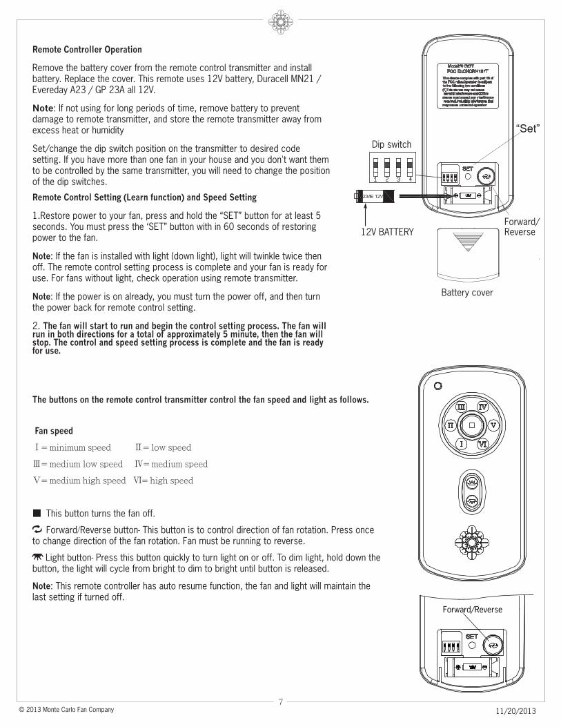
Remote Controller Operation
Remove the battery cover from the remote control transmitter and install battery. Replace the cover. This remote uses 12V battery, Duracell MN21 / Evereday A23 / GP 23A all 12V.
Note: If not using for long periods of time, remove battery to prevent damage to remote transmitter, and store the remote transmitter away from excess heat or humidity
Set/change the dip switch position on the transmitter to desired code setting. If you have more than one fan in your house and you don't want them to be controlled by the same transmitter, you will need to change the position of the dip switches.
Remote Control Setting (Learn function) and Speed Setting
1.Restore power to your fan, press and hold the “SET” button for at least 5 seconds. You must press the ‘SET” button with in 60 seconds of restoring power to the fan.
Note: If the fan is installed with light (down light), light will twinkle twice then off. The remote control setting process is complete and your fan is ready for use. For fans without light, check operation using remote transmitter.
Note: If the power is on already, you must turn the power off, and then turn the power back for remote control setting.
2. The fan will start to run and begin the control setting process. The fan will run in both directions for a total of approximately 5 minute, then the fan will stop. The control and speed setting process is complete and the fan is ready for use.
12V BATTERY
The buttons on the remote control transmitter control the fan speed and light as follows.
Fan speed
Ⅰ= minimum speed Ⅱ= low speed
Ⅲ= medium low speed Ⅳ= medium speed
Ⅴ= medium high speed Ⅵ= high speed
■ This button turns the fan off.
Forward/Reverse button- This button is to control direction of fan rotation. Press once to change direction of the fan rotation. Fan must be running to reverse.
Light button- Press this button quickly to turn light on or off. To dim light, hold down the button, the light will cycle from bright to dim to bright until button is released.
Note: This remote controller has auto resume function, the fan and light will maintain the last setting if turned off.
Dip switch
“Set”
Battery cover
Forward/Reverse
Forward/Reverse

8© 2013 Monte Carlo Fan Company 11/20/2013
The receiver provides the following protective functions
Lock protection- The DC motor has a build-in safety feature against blade obstruction during operation. If something obstructs the fan blades the motor will stop operation after 30 seconds of interruption. Please remove obstacles and reset.
Over 80W protection- When the receiver detects motor power consumption which is greater than 80W, the receiver power will shut down and fan operation will cease. Disconnect the power supply and return power on to the fan after 5 seconds.
Tips for end users
1. If your fan is operated automatically after installation and power on, it is because your fan is still memorize the previous setting at factory. Make Remote control setting (learn function) and your fan will be ready for use.
2. If fan or light isn’t working, reset power (turn the power off for at least 5 seconds and then turn the power back) and redo the remote setting.
3. It is not available to separately operate the remote setting for more than one fan in the same room (in the area where remote signal can reach to) if they share the same power supply. Separate power supplies (like as using individual wall switches for each fan) is required if you want to separately control more than one fan in same room.
Install Transmitter wall mount cradle with 2 screws provided.Move the trim plate out from wall mount cradle and install the wall mount cradle with 2 screws provided. Replace the trim plate.
Trim plate
Wall mount cradle

9© 2013 Monte Carlo Fan Company 11/20/2013
Trouble Shooting
Warning
CAUTION
CAUTION
CAUTION
WARNING
Trouble Suggested Remedy
Nov.2013Nov.2014 add a note on steps 14 and 14