Embed Size (px)
Citation preview
National Vacuum Equipment
Owner’s Manual&
Operating InstructionsModels 4307 & 4310 Blower
www.fraserwoods.ca
Authorized NVE Distributor, Service & Repair Facility 120 – 10293 276 ST, Acheson, Alberta, Canada T7X 6A5
T: 780.962.1827 F: 780.962.1830 E: [email protected]

2 | 4307 & 4310 Blower
© 2013 National Vacuum Equipment, Inc.1212 R/5
4307 & 4310 Blowers
Owner’s Record
Date of Purchase: _________________________
Purchased from: __________________________
Serial Number: ____________________________
All product names, trademarks and registered trademarks are property of their respective owners.
www.fraserwoods.ca

4307 & 4310 Blower | 3
Table of ContentsIntroduction
About National Vacuum Equipment, Inc...............................................................5
Our History ..............................................................................................................5
Limited Warranty
Warranty ..................................................................................................................6
Warranty Procedures..............................................................................................7
Overview
General Blower Operation .....................................................................................8
General Blower Construction.................................................................................8
Location of Serial Number .....................................................................................9
Specifications
Operating Environment ..........................................................................................9
Operating Limits ......................................................................................................9
Performance (Reference Only) ............................................................................10
Dimensions ............................................................................................................11
Air Flow Control ....................................................................................................11
Sound Level ...........................................................................................................11
Limitations on Use ................................................................................................12
Storage
Unpacking Blower .................................................................................................13
Handling ................................................................................................................13
Preservation ..........................................................................................................13
Installation
Rotation and Airflow ............................................................................................14
Diesel Engine Precautions ....................................................................................14
Direct Coupler Installation & Alignment .............................................................15
Belt Drive ...............................................................................................................15
Drive Shaft .............................................................................................................16
Hydraulic Drive ......................................................................................................16
PTO Drive ...............................................................................................................16
Plumbing and Piping .............................................................................................16
www.fraserwoods.ca

4 | 4307 & 4310 Blower
Recommended Accessories
Exhaust Silencer ....................................................................................................17
Tunable Ballast Silencer ........................................................................................17
Inlet Filter ...............................................................................................................17
4-Way Valve and Hoses ........................................................................................17
Pressure Relief Valve .............................................................................................18
Vacuum Relief Valve..............................................................................................18
Check Valves ..........................................................................................................18
Primary Shutoff .....................................................................................................18
Secondary Shutoff/Moisture Trap .......................................................................18
Bag House ..............................................................................................................18
Operation
Initial Start Up Preliminary Checks ......................................................................19
Starting the Blower ...............................................................................................19
Operating ..............................................................................................................20
Stopping the Blower .............................................................................................20
Cold Weather Operation ......................................................................................20
Maintenance
Maintenance Schedule .........................................................................................21
Oil Capacities and Recommendations ................................................................22
Rebuilding ..............................................................................................................22
Gear Casing Lube ..................................................................................................22
Clean Out Procedure If Flooded ..........................................................................23
Blower Oil Capacity ...............................................................................................23
Gearbox Lubricant ................................................................................................23
4307 Blower Maintenance ...................................................................................24
4307 Parts Diagram ..............................................................................................26
4310 Parts Diagram ..............................................................................................27
4307 & 4310 Parts List ........................................................................................28
4307 4-Way Intake Manifold Parts Diagram & Parts List ...................................30
4310 4-Way Intake Manifold Parts Diagram & Parts List ...................................34
Troubleshooting ........................................................................................................36
www.fraserwoods.ca

4307 & 4310 Blower | 5
Introduction
About National Vacuum Equipment, Inc.
Congratulations! You now own a quality vacuum/pressure blower proudly manu-factured in the U.S.A. by National Vacuum Equipment, Inc. You have not only acquired a superior piece of equipment from a qualified dealer, you have hired a team of vacuum experts. We stand ready to work with your dealer to answer your questions and provide you with the information necessary to keep your equipment in peak working condition. Thank you for using National Vacuum Equipment. OUR MISSION: We are dedicated to the manufacture and wholesale distribution of quality vacuum system products at a reasonable price, on a timely basis. We are a “one-stop shop” for manufacturers and distributors of vacuum equipment.
Our History
National Vacuum Equipment, Inc. was founded in 1980 by Bruce Luoma. The Company started as a retailer of vacuum pumps. Soon after it started, the Com-pany secured the rights to exclusive distribution of the Battioni vacuum pumps in North America. This helped the Company to evolve into its current status as a wholesale supplier. To reach the goal of becoming a full service supplier of vacuum system components, the Company began fabricating its own line of com-ponents, purchased and developed its own line of vacuum pumps, and began purchasing for resale various valves and accessories. Today, NVE has full service machine and fabrication shops complete with CNC-controlled production equip-ment designed for close tolerance work. The company has a highly trained staff all of whom are dedicated to quality.
www.fraserwoods.ca

6 | 4307 & 4310 Blower
Limited WarrantyWarranty
National Vacuum Equipment, Inc. guarantees that the product it provides is free of manufacturer’s defects, including materials and workmanship. Properly installed and maintained product is warranted for a period of one (1) year subject to the following conditions:
1. A properly completed warranty registration card must be received by us within 30 days of sale to end user for pump sales to be considered warrantable. All pumps received for warranty consideration must retain the original NVE serial number tag.
2. The one (1) year period shall begin the day the product is shipped from our warehouse, unless we are provided with an authentic copy of the original resale invoice, in which case the one (1) year period shall begin at such invoice date.
3. The covered product must be used in an application for which it wasintended. We do not recommend our product for particular uses or applications.
4. Damage caused by improper use or lack of proper maintenance isnot warrantable.
5. Manufacturer’s liability under this or any other warranty, whether express or implied, is limited to repair of or, at the manufacturers’ op-tion, replacement of parts which are shown to have been defective when shipped.
6. Manufacturer’s liability shall not be enforceable for any product until National Vacuum Equipment, Inc. has been paid in full for such product.
7. Except to the extent expressly stated herein, manufacturer’s liability for incidental and consequential damage is hereby excluded to the full extent permitted by law.
8. Manufacturer’s liability as stated herein cannot be altered except in writing signed by an officer of National Vacuum Equipment, Inc.
9. Certain products provided by National Vacuum Equipment, Inc. are covered by their respective manufacturer’s warranties (e.g., engines used in the NVE engine drive packages). These products are not covered by the National Vacuum Equipment, Inc. Manufacturer’s Warranty.
www.fraserwoods.ca

4307 & 4310 Blower | 7
Warranty Procedures
Should a potential warranty situation arise, the following procedures must be followed:
· Contact your dealer immediately upon the occurrence of the eventand within the warranty period.
· Customer must receive a return goods authorization (RGA) before returning product.
· All serial-numbered products must retain the NVE serial number tag tobe qualified for warranty.
· Product must be returned to NVE intact for inspection before warranty will be honored.
· Product must be returned to NVE freight prepaid in the mosteconomical way.
· Credit will be issued for material found to be defective upon our inspection, based upon prices at the time of purchase.
www.fraserwoods.ca

8 | 4307 & 4310 Blower
Overview
General Blower Operation
The NVE BLOWERS are severe duty vacuum pumps, designed to be used in liquid waste pumping systems where extended operation is desired. The pump incorporates a ballast air cooling system to provide superior cooling, allowing for extended operation.
The air enters the intake under vacuum or at atmospheric pressure. As the rotors rotate, a fixed volume of air is moved along the wall of the cylinder towards the exhaust where the pressure and temperature of the volume of air increases. If the intake air is below atmospheric pressure, cooling air will be drawn in when the rotor tip passes the ballast port.
The airflow capacity of the machine (in ACFM) is nearly proportional to the speed of the machine and is nearly constant with changes in inlet or outlet pressures.
General Blower Construction
BALLAST INJECTION
BALLAST INJECTION
INTAKEEXHAUST
BLOWER HOUSINGDRIVE ENDPLATENON-DRIVE ENDPLATEDRIVE OIL
TANK
DRIVE ROTOR
IDLER ROTOR
DRIVE BEARINGS NON-DRIVE BEARINGS
OIL SLINGER
OIL SLINGERTIMING GEARS
SEAL SLEEVE
SEAL RINGS
SEAL VENT
www.fraserwoods.ca

4307 & 4310 Blower | 9
Sereial Number
Location of Serial Number
Each blower should have a brass colored tag with an embossed serial number. In addition, the serial number and blower direction as assembled at the factory are stamped into the top of the housing as shown:
Specifications
Operating Environment
The 4307 and 4310 blowers are designed to move atmospheric air. Do not use to move explosive or corrosive gasses or operate the blower in an area with explosive gases. Any materials in the intake air must be filtered and separated from the air by means of an intake filter, mois-ture trap and/or a cyclonic filter.
The ballast inlet must be positioned and protected from ingesting debris, fluid or explosive gases.
Operating Limits
The blower must be operated within all limits at all times. This typically means the blower performance is limited by the exhaust temperature and temperature rise over ambient for the blower.
*Exhaust temp and temp rise limited, †Pressure rise is from inlet to outlet, ‡Temperature rise is exhaust minus ambient temperature surrounding blower (note if enclosed)
Inlet VacPressure Rise†(psig)
ExhuastPressure(psig)
InletTemp(°F)
ExhuastTemp(°F)
Temp. Rise‡ (°F)
Ballast InletTemp(°F)
Max Min Max Max Max -‐ Max Max -‐4307 4000 900 FULL VAC 14 10 * 380 235 *4310 4500 900 FULL VAC 14 10 * 380 260 *
RPMSize
www.fraserwoods.ca

10 | 4307 & 4310 Blower
Performance (Reference Only)
ACFM - Actual CFM generated on the vacuum or pressure side of the machine
B.O. - Blanked Off
Vacuum (Inches of Mercury) Pressure (PSI)
RPM 0 9 15 18 21 24 27 5 10 15 18
2000HP 2.0 7.4 11.0 12.8 14.6 16.4 - 8.1 14.2 20.3 24.0
CFM 280 171 114 77 26 - - 183 143 113 97
2500HP 2.5 9.2 13.7 16.0 18.2 20.5 - 10.1 17.7 25.4 29.9
CFM 349 241 184 147 96 17 - 253 213 183 167
3000HP 3.0 11.1 16.5 19.2 21.9 24.6 27.3 12.1 21.3 30.4 35.9
CFM 419 311 254 217 166 87 - 323 283 253.0 237.0
3500HP 3.5 12.9 19.2 22.4 25.5 28.7 31.8 14.2 24.8 35.5 41.9
CFM 489 381 324 286 236 157 - 393 353 322.0 307.0
4000HP 4.0 14.8 22.0 25.6 29.2 32.8 36.4 16.2 28.4 40.6 47.9
CFM 559 451 394 356 306 227 57 463 423 392 376
When installing a NVE 4307 blower we recommend a normal R.P.M. range from 2700 to 4000. Other speeds are o.k. as long as exhaust gas temperatures read on the supplied thermometer do not exceed 290 degrees F over ambient temperature.
4307
0 18 24 27 10
2 17.8 23.1 - 24.8
500 407 255 - 324
4 35.6 46.1 51.4 39.7
826 661 528 182 631
4.5 40 51.9 57.8 44.7
931 763 660 270 733
RPM
2400Hp.CFM
Pressure (PSI)Inches of Vacuum (Hg)
4000
4500Hp.
CFM
Hp.CFM
Maximum 4500 RPM Intermittent Operation Only.
The maximum allowable operating vacuum will vary depending on R.P.M., ambient temperature, altitude and time running. The basic principle to keep in mind is - faster R.P.M., higher air temperature and longer run time all equal more heat in the pump. When installing an NVE 4310 blower we recommend a normal R.P.M. of 4000. Other speeds are o.k. as long as exhaust gas temperatures read on the supplied thermometer do not exceed 375 degrees F.
4310
www.fraserwoods.ca

4307 & 4310 Blower | 11
Dimensions
Air Flow Control
The airflow rate on the blower can be adjusted by changing the speed of the blower. This can be accomplished by changing the PTO ratio, gearbox ratio, belt drive pulley diameters or engine speed.
Sound Level
It is recommended the operator monitor the blower while running and listen for resonances (increased levels of noise) that may occur at certain RPM’s and operate the blower at speeds above or below the resonance speeds to reduce excess noise.
The noise level of the blower may increase with higher levels of vacuum and RPM. To minimize noise, operate the blower at the minimum speed and vacuum level required to achieve the desired performance results.
131-4310-LDBCW ROTATION
SCALE 1 / 4
131-4310-LSBCCW ROTATION
SCALE 1 / 4DIMENSIONS SYMMETRICAL TO LDB BLOWER
DETAIL CSCALE 1 / 2
1
1
2
2
3
3
4
4
5
5
6
6
7
7
8
8
A A
B B
C C
D D
NVE NationalVacuum
Equipment, Inc.2670 Aero Park Drive, Traverse City, MI 49686Phone: (231) 941-0215 Fax: (231) 941-2354
TOLERANCES UNLESS OTHER WISE SPECIFIED
One place (.X) ±.1Two places (.XX) ±.01Three places (.XXX) ±.005Angles ±1°
All machined surfaces 125 RMS max.Remove all burrs and sharp edges.CAD drawing - NO manual changes.All dimensions in inches unless specified.
This document may contain confidential tradesecret information which is the exclusive
property of National Vacuum Equipment. Anyinformation on this drawing is not to be
disclosed to anyone not having a "Need toKnow." The information contained herein is to
be used only in accordance with the bestinterests of National Vacuum Equipment.
PART NAME:
MATERIAL:
DRAWN BY:
SCALE:
CHECKED BY:
DATE:
BOB
PART NO.SHEET
2 131-4310LDB AND LSB2 of
1/4
SEE BOM
APPROX. WT.CAD FILE LOCATION: P:\Data\CAD - Production\131-4310-LDB & LSB.idw
SHEET SIZE D333 LBS
BLOWER, 4310 CW & CCW W/ BALLAST
C
.13 .40.250
STAMP DIRECTION AND SERIAL NUMBER INTO HOUSING AS SHOWN
(6.710)
(1.499)(.375)SQ KEY
(1.657)
(.157)(2.375)(1.250)
(3.350)
(6.700)
(12.625) (9.805)
1/2-13 UNC - 2B .750
(17.701) (7.326)
(7.693)
(9.875)
(17.690)
(15.813)
(6.000)(6.313)
1/2-13 UNC - 2B .875
(8.500)
(8.875)
OIL FILL PORTDRIVE END9/16" HEX
OIL FILL PORTNON-DRIVE END
9/16" HEX
OIL DRAIN PORTDRIVE END9/16" HEX
OIL DRAIN PORTNON-DRIVE END9/16" HEX
(5.920) BC
1/2-13 UNC - 1B 1.250
(4.000)PILOT
(13.943)
REVISION HISTORYREV DATE DESCRIPTION APPROVED ZONE
F 10/22/2010
CHD'D FRONT OIL TANK, BRNG RETAINER TO 1/4" FASTENER,CORRECTED NOTE 6 (262 WAS
620)
ECN 1120 B4
G 11/10/2010
P/N LDB AND LSB WAS LD AND LS, ADDED CAST ALUM
BALLAST MANIFOLDS AND SEALING WASHERS,
LENGTHENED BALLAST BOLTS 1/4", CHG'D HOSE CLAMPS.
ECN 1186 A1
(6.915)
www.fraserwoods.ca

12 | 4307 & 4310 Blower
Limitations on Use
Limitation on Use Reason for Limitation and/or Risk
Corrective Actions
Operation of the blower in an explosive environment
Fire and/or explosion can result
DO NOT USEUsing blower to move explo-sive, toxic or dangerous gases
Fire and/or explosion can result
Pollution of the environment
Health risks to operators
Liquid drawn into blower intake
Blower seizure, damage to blower and ejection of parts
Install a moisture trap or cyclonic separator on the intake nozzle of the blower.
Operation with the exhaust or ballast blocked off.
Overheating Remove the blockage and minimize restriction in the exhaust or ballast circuits
Rotating blower in wrong direction
Damage to blower Change the direction of ro-tation of the drive or order correct rotation of blower.
Operating in excess of recom-mended speed
Seizure of blower, damage to blower and ejection of parts Operate the blower within
recommended speed rangeOperating blower below minimum speed
Seizure of blower, damage to blower and ejection of parts
Exceeding the maximum pressure rise from blower inlet to outlet
Overheat of Blower
Fire
Seizure of blower, damage to blower and ejection of parts
Check inlet and exhaust restrictions and reduce as necessary.
Operating at excessively hot inlet or ballast temperatures
Overheating
Fire
Seizure of Blower, damage to blower and ejection of parts
Monitor the inlet tempera-ture and make corrections to the system to bring tem-perature within limits.
Operating at excessively cold inlet temperatures.
Seizure of Blower, damage to blower and ejection of parts
Review precautions in cold weather conditions. Use recommended lubrication.
Operating above the exhaust temperature upper limit
Overheating
Fire
Seizure of Blower, damage to blower and ejection of parts
Reduce the vacuum level in high ambient conditions.
Reduce the blower speed.
Remove restrictions in the intake and exhaust circuits.
Operating in excess of the specified temperature rise across the blower
Seizure of Blower, damage to blower and ejection of parts
Reduce the vacuum or pres-sure level to bring within limits.
www.fraserwoods.ca

4307 & 4310 Blower | 13
Storage
Unpacking Blower
When unpacking the blower or blower package from the skid, verify the packing list matches the product supplied and that no visible damage has occurred during shipping. In the event damage has occurred, first file a claim with the carrier and then contact NVE for assistance.
Keep all intake, exhaust and ballast ports covered to prevent accidental ingestion of materials into the blower.
Handling
Use an appropriately sized lift strap for lifting the blower. Thread two 1/2-13 UNC x 4” LG grade 8 bolts into the flange holes as shown.
Preservation
Keep all intake, exhaust and ballast port coverings in place to prevent debris or liquids from entering blower. Reapply rust preventative oil to all metal parts, including the compression chamber every 6 months or more frequently if the relative humidity is greater than 80%.
While in storage, rotate the shaft three to four revolutions every two weeks to keep gears coated in oil.
Before installing a blower that has been stored for any length of time, remove the intake and exhaust covers and inspect the rotors and cylinders to insure the absence of rust. In addition, remove the oil fill plug on drive oil tank and inspect the gear for absence of rust.
Model Weight (lbs)4310-‐LD 3184310-‐LDB 3384310-‐LDM 4264307-‐LD 2704307-‐LDM 412
4310
4307
www.fraserwoods.ca

14 | 4307 & 4310 Blower
131-4310-LDBCW ROTATION
SCALE 1 / 4
131-4310-LSBCCW ROTATION
SCALE 1 / 4DIMENSIONS SYMMETRICAL TO LDB BLOWER
DETAIL CSCALE 1 / 2
1
1
2
2
3
3
4
4
5
5
6
6
7
7
8
8
A A
B B
C C
D D
NVE NationalVacuum
Equipment, Inc.2670 Aero Park Drive, Traverse City, MI 49686Phone: (231) 941-0215 Fax: (231) 941-2354
TOLERANCES UNLESS OTHER WISE SPECIFIED
One place (.X) ±.1Two places (.XX) ±.01Three places (.XXX) ±.005Angles ±1°
All machined surfaces 125 RMS max.Remove all burrs and sharp edges.CAD drawing - NO manual changes.All dimensions in inches unless specified.
This document may contain confidential tradesecret information which is the exclusive
property of National Vacuum Equipment. Anyinformation on this drawing is not to be
disclosed to anyone not having a "Need toKnow." The information contained herein is to
be used only in accordance with the bestinterests of National Vacuum Equipment.
PART NAME:
MATERIAL:
DRAWN BY:
SCALE:
CHECKED BY:
DATE:
BOB
PART NO.SHEET
2 131-4310LDB AND LSB2 of
1/4
SEE BOM
APPROX. WT.CAD FILE LOCATION: P:\Data\CAD - Production\131-4310-LDB & LSB.idw
SHEET SIZE D333 LBS
BLOWER, 4310 CW & CCW W/ BALLAST
C
.13 .40.250
STAMP DIRECTION AND SERIAL NUMBER INTO HOUSING AS SHOWN
(6.710)
(1.499)(.375)SQ KEY
(1.657)
(.157)(2.375)(1.250)
(3.350)
(6.700)
(12.625) (9.805)
1/2-13 UNC - 2B .750
(17.701) (7.326)
(7.693)
(9.875)
(17.690)
(15.813)
(6.000)(6.313)
1/2-13 UNC - 2B .875
(8.500)
(8.875)
OIL FILL PORTDRIVE END9/16" HEX
OIL FILL PORTNON-DRIVE END
9/16" HEX
OIL DRAIN PORTDRIVE END9/16" HEX
OIL DRAIN PORTNON-DRIVE END9/16" HEX
(5.920) BC
1/2-13 UNC - 1B 1.250
(4.000)PILOT
(13.943)
REVISION HISTORYREV DATE DESCRIPTION APPROVED ZONE
F 10/22/2010
CHD'D FRONT OIL TANK, BRNG RETAINER TO 1/4" FASTENER,CORRECTED NOTE 6 (262 WAS
620)
ECN 1120 B4
G 11/10/2010
P/N LDB AND LSB WAS LD AND LS, ADDED CAST ALUM
BALLAST MANIFOLDS AND SEALING WASHERS,
LENGTHENED BALLAST BOLTS 1/4", CHG'D HOSE CLAMPS.
ECN 1186 A1
(6.915)
· Use a rust preventative oil with a flash point over 400°F
· Dispose of used rust preventative oil according to local regulations
Installation
Rotation and Airflow
Diesel Engine Precautions
· DO NOT OPERATE BLOWER WITH A DIESEL ENGINE RUNNING AT LOW RPM’S AS TORQUE PULSES CAN CAUSE ROTOR LOBE CONTACT AND DAMAGE TO THE BLOWER.
When directly driving the blower with Diesel engine, bring the engine up to oper-ating RPM and then engage the blower via the clutch. Be sure to start the blower under no load conditions.
Use caution when using a Diesel engine that is significantly oversized for the operating point of the blower. Doing so can result in an inertial mismatch, excess torsional vibrations at low RPM’s and blower lobe contact.
Direct Coupler Installation and Alignment
Slide the couplers onto the blower shaft and prime mover shaft using appropriate tools.
CW Blower CCW Blower
131-4310-LDBCW ROTATION
SCALE 1 / 4
131-4310-LSBCCW ROTATION
SCALE 1 / 4DIMENSIONS SYMMETRICAL TO LDB BLOWER
DETAIL CSCALE 1 / 2
1
1
2
2
3
3
4
4
5
5
6
6
7
7
8
8
A A
B B
C C
D D
NVE NationalVacuum
Equipment, Inc.2670 Aero Park Drive, Traverse City, MI 49686Phone: (231) 941-0215 Fax: (231) 941-2354
TOLERANCES UNLESS OTHER WISE SPECIFIED
One place (.X) ±.1Two places (.XX) ±.01Three places (.XXX) ±.005Angles ±1°
All machined surfaces 125 RMS max.Remove all burrs and sharp edges.CAD drawing - NO manual changes.All dimensions in inches unless specified.
This document may contain confidential tradesecret information which is the exclusive
property of National Vacuum Equipment. Anyinformation on this drawing is not to be
disclosed to anyone not having a "Need toKnow." The information contained herein is to
be used only in accordance with the bestinterests of National Vacuum Equipment.
PART NAME:
MATERIAL:
DRAWN BY:
SCALE:
CHECKED BY:
DATE:
BOB
PART NO.SHEET
2 131-4310LDB AND LSB2 of
1/4
SEE BOM
APPROX. WT.CAD FILE LOCATION: P:\Data\CAD - Production\131-4310-LDB & LSB.idw
SHEET SIZE D333 LBS
BLOWER, 4310 CW & CCW W/ BALLAST
C
.13 .40.250
STAMP DIRECTION AND SERIAL NUMBER INTO HOUSING AS SHOWN
(6.710)
(1.499)(.375)SQ KEY
(1.657)
(.157)(2.375)(1.250)
(3.350)
(6.700)
(12.625) (9.805)
1/2-13 UNC - 2B .750
(17.701) (7.326)
(7.693)
(9.875)
(17.690)
(15.813)
(6.000)(6.313)
1/2-13 UNC - 2B .875
(8.500)
(8.875)
OIL FILL PORTDRIVE END9/16" HEX
OIL FILL PORTNON-DRIVE END
9/16" HEX
OIL DRAIN PORTDRIVE END9/16" HEX
OIL DRAIN PORTNON-DRIVE END9/16" HEX
(5.920) BC
1/2-13 UNC - 1B 1.250
(4.000)PILOT
(13.943)
REVISION HISTORYREV DATE DESCRIPTION APPROVED ZONE
F 10/22/2010
CHD'D FRONT OIL TANK, BRNG RETAINER TO 1/4" FASTENER,CORRECTED NOTE 6 (262 WAS
620)
ECN 1120 B4
G 11/10/2010
P/N LDB AND LSB WAS LD AND LS, ADDED CAST ALUM
BALLAST MANIFOLDS AND SEALING WASHERS,
LENGTHENED BALLAST BOLTS 1/4", CHG'D HOSE CLAMPS.
ECN 1186 A1
(6.915)
www.fraserwoods.ca

4307 & 4310 Blower | 15
· DO NOT USE A HAMMER TO SLIDE THE COUPLERS ONTO THE SHAFT AS THIS MAY RESULT IN BLOWER DAMAGE
· Failure to properly align the couplers can cause premature wear of the blower bearings and coupler sleeve.
· Couplers must be guarded to prevent entanglement.
Belt Drive
All NVE blower input shafts are equipped with an outboard roller bearing which allows the use of V-belt.
The driving pulley from the prime mover must be mounted on the intake side of the blower to prevent unloading of the blower bearings.
Use a narrow hub sheave and insure that the inner hub face is not more than 1/4” from the face of the gearbox. Be sure to also use an adjustable belt tensioning system to allow compensation for belt wear.
· Excessive belt tension could damage the blower and prime mover.
· Belts and pulleys must be guarded to prevent entanglement.
Use matched sets of V-belts to insure uniform torque transmission. If a belt goes out, replace the whole set.
· Use a rust preventative oil with a flash point over 400°F
· Dispose of used rust preventative oil according to local regulations
Installation
Rotation and Airflow
Diesel Engine Precautions
· DO NOT OPERATE BLOWER WITH A DIESEL ENGINE RUNNING AT LOW RPM’S AS TORQUE PULSES CAN CAUSE ROTOR LOBE CONTACT AND DAMAGE TO THE BLOWER.
When directly driving the blower with Diesel engine, bring the engine up to oper-ating RPM and then engage the blower via the clutch. Be sure to start the blower under no load conditions.
Use caution when using a Diesel engine that is significantly oversized for the operating point of the blower. Doing so can result in an inertial mismatch, excess torsional vibrations at low RPM’s and blower lobe contact.
Direct Coupler Installation and Alignment
Slide the couplers onto the blower shaft and prime mover shaft using appropriate tools.
www.fraserwoods.ca
16 | 4307 & 4310 Blower
Drive Shaft
U-Joint operating angles at each end of the shaft should always be at least 1° to prevent yoke bearing failure, but do not exceed the manufacturers maximum recommended angles for the operating RPM.
U-Joint operating angles on each end of a driveshaft should always be equal within 1° of each other to cancel an angle vibration.
For more driveline installation detail, please see the Dana-Spicer Driveline Instal-lation Document J3311-1-DSSP available free from http://www2.dana.com/pdf/J3311-1-DSSP.pdf.
· Use a drive shaft loop to catch shaft in the event of failure.
· It is suggested that overload protection be used on the blower driveline.
Hydraulic Drive
The blower can be driven with an appropriately sized hydraulic system utilizing a hydraulic motor with an SAE B or C, 4-bolt or 2-bolt flange by purchasing a hydrau-lic mount (purchased separately) and appropriate couplers.
PTO Drive
PTO’s must be properly sized to drive the blower. For more information on driving blowers with PTO’s, please see the Chelsea Blower Torque Guide Bulletin HY25-0075-B1-US available at www.parker.com .
· Improper use of “Hot Shift” (i.e. clutch type, constant mesh) PTO’s can result in severe damage to the blower driveline and blower. Take extra precautions to operate PTO’s within the manufacturer’s recommendations
Plumbing and Piping
Do not hang plumbing from blower flanges. Use isolating flanges or isolating hose to couple blower to piping to prevent dead weight from hanging off blower and to allow for thermal expansion. Failure to do so may result in rotor contact with housing. Use only clean piping insuring it is free of dirt, scale, cuttings, weld spat-ter, and foreign materials of any kind.
www.fraserwoods.ca

4307 & 4310 Blower | 17
The intake and exhaust system can be plumbed with 4” or 6” hose. Four inch hose will provide a more compact system while the 6” hose will maximize the efficiency of the system.
The ballast system should be plumbed using 4” hose minimum. Be sure to locate the ballast inlet away from heat, debris and fluid sources as exposure to these may result in damage to the blower.
Recommended Accessories
Exhaust Silencer
Positive displacement blowers are inherently noisy due to their design. NVE offers compatible silencers for the exhaust to reduce decibel levels in the operating environ-ment.
If using a non-OEM silencer, it should be tested for effectiveness by blanking off the inlet and monitoring exhaust gas temperature with the blower running for at least one hour. The blower should not exceed specified exhaust gas temperatures.
Tunable Ballast Silencer (4310 Blower)
A tunable ballast silencer provides for field tuning of the ballast circuit to minimize the noise for customer specific operating points.
If using a non-OEM silencer, it should be tested for effectiveness in the same fashion as described above for exhaust silencers.
Inlet Filter
The intake filters are designed to ensure maximum airflow efficiency why keeping out unwanted debris. The filters supplied by NVE use a stainless steel screen and can be cleaned.
Four Way Valve and Hoses
If it is intended to operate the blower in the pressure mode, a four way valve will be required. The 4-way valve size should match the hose size used in the application.
www.fraserwoods.ca

18 | 4307 & 4310 Blower
4-Way Plug Adjustment Procedure:Use at initial installation or for adjustment use steps 6 to 10.
1. Remove all hardware from center thread 2. Install Brass washers and place handle into proper fit position based on your installation direction. 3. Install cup washer and adjusting nut and secure to at least finger tight. 4. Turn the adjusting nut a half to ¾ turn to pull the plug off seat position 5. Test valve movement: Valve should move freely 6. If valve does not move freely, review for other obstructions or tighten adjusting nut by ¼ turn until free movement occurs. 7. Once free movement is established install jam nut until finger tight 8. Use two wrenches and tighten jam nut while holding adjustment nut steady 9. Test valve movement: Valve should move freely 10. Valve is now adjusted and ready for installation.Note: Use narrow wrench to hold adjusting nut while tightening jam nut.
Dry Lubed Bronze Thrust Washer
Adjusting Nut
Jam Nut
Four Way Valve cont.
Pressure Relief Valve
If the blower is intended to be used in pressure mode then a pressure relief valve is required. NVE recommends the use of Kunkle pressure relief valves as they have been proven to work well and have sufficient flow capacity.
1 2 3
Picture 1. 1. Unscrew the lock nut “A” 2. Turn the spring-tightener “B”
Picture 2. Once obtained the desired pressure, screw down the lock nut “A”
Picture 3. Fix the setting, using the rings “C” Situated on the body and on the spring tightener
Pressure Relief Valve Setting Instructions
Pressure Relief Valve
www.fraserwoods.ca
4307 & 4310 Blower | 19
Check Valves
For vacuum only setups, the blower system will need to have an appropriately sized check valve on the inlet side of the blower.
If the blower is to be operated in a pressure mode, a check valve will need to be used on both the ballast air system and the intake side of the blower. Note that the ballast circuit normally draws air into the blower.
Use the same size check valve as the hose used to plumb the system.
Primary Shutoff
A primary shutoff is to be used with the blower as a first line of defense to prevent liquid from entering the blower. It is critical that an appropriately sized primary shut off is used. Contact NVE for assistance with selecting the shutoff.
Secondary Shutoff/Moisture Trap
The secondary shutoff or moisture trap should also be appropriately sized for the air flow application. Contact NVE for assistance with selecting the shutoff.
Bag House
Bag houses are typically used in systems where dry material is being pumped. Specification of a proper bag house depends on the frequency and type of dry material being pumped. Consult the factory for assistance in selecting a bag house.
Operation
Initial Start Up Preliminary Checks
Before operating a blower that has been stored for any length of time, remove the intake and exhaust covers and inspect the rotors and cylinders to insure the absence of rust. In addition, remove the oil fill plug on the drive oil tank and inspect the gear for absence of rust.
Verify the blower spins freely by hand.
Verify all connections between the plumbing system and the blower flanges are in place and tight.
www.fraserwoods.ca

20 | 4307 & 4310 Blower
Initial Start Up Preliminary Checks Cont. Verify oil levels through sight eyes. If additional oil is required, see the maintenance section for details.
Verify the blower is set-up to spin the correct direction, especially when using a gearbox.
Verify all guards are in place.
· Insure personnel wear hearing protection as noise levels can exceed 85 dB.
· Do not rotate the blower in the reverse direction.
Starting the blower
HOT Shift PTO’s - Do not engage “Hot Shift PTO’s” outside of manufacturers specifications as damage to the PTO, driveline or blower may occur. Slowly ramp the blower up to speed to prevent shocking the system.
Increase the vacuum level slowly until the rated level is reached. During the first 8 hours of operation, check that there are no vacuum leaks, oil leaks, vibrations or strange noises.
Operating
Start the blower and check the appropriate parameters as listed in the mainte-nance schedule under the Maintenance section.
Stopping the Blower
When stopping the blower, if possible, remove all vacuum and pressure from the blower.
www.fraserwoods.ca

4307 & 4310 Blower | 21
Cold Weather Operation
During very cold weather conditions, always warm the blower before operating at full rated vacuum or pressure. Damage to the blower can result from operating for short intervals in very cold weather conditions.
If using a coupler with a rubber jaw or sleeve in shear during extremely cold weather, take note that elastomeric materials become stiffer in cold weather. This results in a reduction of the shear protection in the event of a lock up of the blower because the jaw or sleeve can handle more torque before giving way.
If hydraulically driving the blower, allow the hydraulic fluid to warm up before operating the blower at full load. Use the correct viscosity of hydraulic oil for the operating temperature as recommended by the manufacturer of your system.
Before starting blower, verify the shaft rotates freely by hand. Water can condense and freeze in the blower cylinder without warning causing a stall condition at start up.
Check the intake filter and air intake daily. If snow is present, check the air intake more frequently.
DO NOT thin out the oil in the gear cases with any other fluids such as Kerosene. Use the recommended oil for the operating temperatures.
If temperatures are so cold that the blower cannot warm up, enclose the blower allowing for sufficient clearance from parts to prevent contact with hot or moving components.
www.fraserwoods.ca

22 | 4307 & 4310 Blower
Maintenance· LOCK OUT any equipment before performing maintenance.
· Remove all pressure and vacuum from the system, i.e. discharge any stored energy in the system.
· Allow the blower to cool to below 100°F before beginning work to prevent burns.
MAINTENANCE SCHEDULE
CHECK PARAMETERFREQUENCY
COMMENTSH D W M
VISUAL
Pressure 1
Blower Running
Temperature 1
Load-Absorbed Power
1
Noise 1
LUBRICATION
Oil Level 1
Blower Shutdown
Oil Leakage 1
Viscosity 500
Oil Change-Initial 500
Oil Change-Normal 1000 6
FILTERVacuum 1 <1 in Hg
Clogging 2
DRIVETRAIN
Wear 2000
Blower Shutdown
Belt Tension 2000
Belt Change 15000 24
RIGHT ANGLE GEARBOX
Oil Change-Initial 500
Oil Change-Normal 1000 6
MOISTURE TRAP/ SECONDARY
Drain Fluid 1
www.fraserwoods.ca

4307 & 4310 Blower | 23
Oil Capacities and Recommendations The initial oil change on the blower is after 500 hours of operation per the maintenance table.
Recommended Oils for Blower (Synthetic Only)
Ambient Temp
°F (°C) Type Viscosity Pour Point Color
Above 90°F (32°C)Summit Syngear SH-7320
Mobile SHC 632ISO 320
-40 (-40)
-40 (-40)
Clear
Orange
32° to 90° (0° to 32°)Summit Syngear SH-7220
Mobil SHC 630 ISO 220
-45 (-43)
-41 (-42)
Clear
Orange
0° to 32° (-18° to 0°)Summit Syngear SH-7150
Mobile SHC 629ISO 150
-60 (-51)
-45 (-43)
Clear
Orange
Below 0° (-18°)Summit Syngear SH-7100
Mobil SHC 627ISO 100
-60 (-51)
-45 (-43)
Clear
Orange
*Ambient temp is the temperature of the space where the blower is located or enclosed.
· Dispose of used oil according to local regulations
RebuildingRebuilding is beyond the scope of this owner’s manual and should be performed only by trained technicians. Consult an authorized distributor or NVE to arrange rebuilding of the blower. Change Gear Casing Lube; first 500 hours, then every 1,000 hours.• Therearethreeseparategearcaseswhichmustbeservicedwith
new ISO 220 synthetic gear lube. Drive end blower. Non drive end blower. Right angle gearbox (for gearbox mount packages)
• Periodicallychecksighteyesforoillevel.(Sighteyeslocatedonright and left sides of the blower on the non drive end.)
www.fraserwoods.ca

24 | 4307 & 4310 Blower
Clean Out Procedure if Flooded1. Remove the inlet filter, exhaust silencer and ballast silencer.2. With high pressure water, clean intake, exhaust and ballast areas.3. Have an assistant slowly turn the input shaft as you clean the lobes with water.4. Run the blower at the lowest speed possible and continue to spray water into the
inlet of the machine until the discharge shows only clean water.5. With the blower running, spray a small amount of penetrating oil into the intake and
run until no liquid comes out the exhaust. DO NOT SPRAY OIL INTO THE BLOWER WITH THE SILENCERS IN PLACE.
6. Disassemble and clean the manifold/4-way valve assembly. Allow to dry then reas-semble.
7. If the blower was flooded, it is highly probable the exhaust silencer has material in it as well. Clean it out as best you can. Drain all fluids from the silencer and allow it to dry.
8. When everything is clean and dry, reassemble the manifold and silencers. Make sure flange bolts on the blower are tightened evenly.
OIL FILL
OIL DRAIN
OIL LEVELWITH BLOWERSHUT DOWN
OIL LEVELSIGHT EYES
CHANGE OIL IN BOTH DRIVE AND NON-DRIVE OIL TANKS
DRIVEEND NON-DRIVE
END
Drive SideOz (Liters)
Non-‐Drive SideOz (Liters)
Total
43074310
SizeBlower Oil Capacity -‐ DO NOT OVERFILL
18 (.53) 8 (.24) 26 (.77)
Size Capacity (oz) Manufacturer Grade500 Series 28 Summit Summit Syngear SH-‐7220600 Series 80-‐90 Mobil Monilube SHC 75W-‐90
Right Angle Gearbox Lubricant
www.fraserwoods.ca

4307 & 4310 Blower | 25
The time intervals between the various maintenance procedures depends greatly on such factors as: • Type of product being pumped• Actual pumping time• Idle equipment (periods of non use)• Set up perimeters (rpm and working vacuum and pressure)• Working climate and conditions
It is therefore up to the operator to adjust the following schedule accordingly.
Lubrication:Unlike a typical rotary vane vacuum pump, the Challenger Series 4307 high vacuum blower does not use oil in it’s operation. Therefore it is important to periodically lubricate the internal parts in the blower to keep it free of rust and corrosion, which can cause seizing or catastrophic failure.
Main Pump Housing – Diesel flush; At least weekly.•Yourblowercomesstandardwithadie-selflushkitinstalled.Thisisusedtoin-troduce small amounts of diesel into the machine to clean out debris and inhibit rust. Note this procedure is also followed daily in cold climates to help keep any moisture that may be in the blower from freezing up.
•Makesurethereservoircontainsdieselfuel.
•Whiletheblowerisrunningatit’slowestrpm setting with the vacuum/pressure change over valve in the neutral position, open the brass valve at the base of the dieselflushreservoirandcloseitafter2seconds.
•Ininstanceswherethereissignificantwaterorproductintheblowerthis process can be repeated as necessary. In that case the drains in the bottom of the silencers should be left open until the process is complete.
4307 Blower Maintenance
www.fraserwoods.ca

26 | 4307 & 4310 Blower
Vacuum/Pressure Changeover Valve; As needed.•Removescrewswhichsecurethebonnetortoptothevalvebody.Alternate
screws as you loosen them to keep the spring evenly compressed.
•Pulluponthehandle,removingtheinnerworkingsofthevalve.Notetheposition of the handle in plug for later reinstallation.
•Generouslylubricatetheinsideofthevalvecasingandtheinnerworkingsofthe valve.
•Makingsuretheo-ringisinplaceonthetopofthevalvehousing,replacetheinner workings in the same position they were removed.
•Tightenthefourfastenersinanalternatemannertomaintainevenpressureon the spring during compression.
•Workthevalvehandlebackandforthseveraltimestoensurefreemovement.
www.fraserwoods.ca

4307 & 4310 Blower | 27
4307
Blo
wer
| P
arts
Dia
gram
www.fraserwoods.ca
28 | 4307 & 4310 Blower
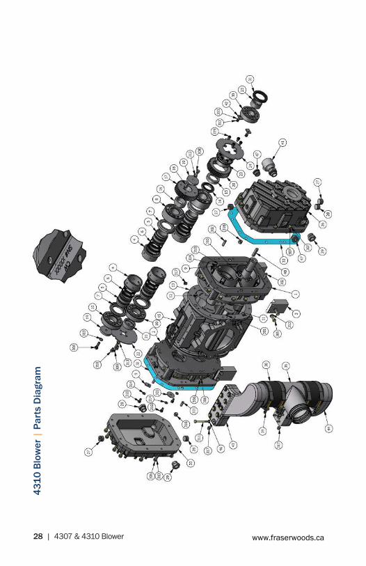
4310
Blo
wer
| P
arts
Dia
gram
www.fraserwoods.ca

4307 & 4310 Blower | 29
4307 & 4310 Blower Complete | Parts List
ITEM QTY PART NUMBER DESCRIPTION
1 1 150-003-4310-1 ENDPLATE, DRIVE 4310 MACH
2 1 150-003-4310-2 ENDPLATE, NONDRIVE 4310 MACH
3 4 150-652-001 MOUNTINGFOOT,4310
4 4 150-630-747 SEAL SLEEVE, OD 4310/747
5 4 150-629-4310 SEAL SLEEVE, ID 4310
6 16 150-618-747 SEALRING,2.5ODCASTIRON
7 4 150-631-747 SLINGER,SHAFTGUARD,747
8 2 150-621-747 BEARING,5309(45X100X39.7)
9 4 150-047-957 BEARINGRETAINER,957
10 2 150-622-747 BEARING,NU309(45X100X25)
11 1 150-005-4307-D ROTOR, DRIVE 4307
11 1 150-005-4310-D ROTOR, DRIVE 4310
12 1 150-005-4307-I ROTOR, IDLER 4307
12 1 150-005-4310-I ROTOR, IDLER 4310
13 1 150-001-4307 HOUSINGMAIN4307
13 1 150-001-4310 HOUSINGMAIN4310
14 1 150-645-747 LOCK NUT DRIVE, ROTOR, 747
15 1 150-641-747 RETAINER, LOCKNUT 747
16 1 150-633-747 SPACER, DRIVE END, FOLLOWER 747
17 1 150-613-747 TIMINGGEAR,IDLER,747
18 1 150-006-001 KEY,.375SQX2"1018+.001/-.000
19 2 150-638-747 RETAINER, IDLER ROTOR 747
20 1 150-612-747 TIMINGGEAR,DRIVE,747
21 1 150-636-747 RETAINER, NONDRIVE END, 747
22 1 150-637-747 OILSLINGER,NON-DRIVEEND747
23 1 150-624-747 B-LOC,RETAININGRING,FLANGED
24 1 150-635-747 OILSLINGER,DRIVEEND747
25 1 150-009-747 SEAL SLEEVE, OUTER
26 1 150-627-747 END COVER, DRIVE END 4310
27 3 120-047 DRAINPLUG,3/4"NPT
28 2 120-047-1 DRAINPLUG,3/4"NPTMAGNETIC
29 3 150-048 SIGHTEYE,11/16"-12SAE
30 1 150-623-747 BEARING,NU308(40X90X23)
31 1 150-620-747 SEAL,50X72X10ASFMK
32 2 150-639-747 GASKET,ENDCOVER747
33 1 150-628-747 OIL COVER, NON-DRIVE 747/4310
36 1 802-650-009 BALLAST TEE W/ RISER, 4307 CAST
36 1 802-650-003A BALLAST TEE, 4310 CAST
www.fraserwoods.ca

30 | 4307 & 4310 Blower
ITEM QTY PART NUMBER DESCRIPTION
38 2 426-300-TAR-4 HOSE,3",TAR&ASPHALT-4INLG
38 2 426-400-TAR-4IN HOSE,4",TAR&ASPHALT-4INLG
39 4 426-3875-TBC CLAMP,T-BOLT3.875"
39 4 426-4625-TBC CLAMP,T-BOLT,4.625"
40 1 120-006 KEY,3/8"X3/8"X2
41 1 150-048-001 SIGHTEYE,90DEG-11/16-12SAE
42 2 150-047-4310 BEARINGRETAINER,4310
43 1 150-650-006 BALLAST MANIFOLD, LH 4307 MACH
43 1 150-650-004 BALLAST MANIFOLD, LH 4310 MACH
44 1 150-650-007 BALLAST MANIFOLD, RH 4307 MACH
44 1 150-650-005 BALLAST MANIFOLD, RH 4310 MACH
45 2 150-616-4307 GASKET,BALLASTMANIFOLD,4307
45 2 150-616-4310 GASKET,BALLASTMANIFOLD,4310
46 12 150-099-008 WASHER,5/16SEALINGBUNA
46 20 150-099-008 WASHER,5/16SEALINGBUNA
47 2 150-047-003 PLUGSAEORB-12
301 4 DP-3/8X1.00 DOWELPIN-3/8X1.00LG
302 2 DP-3/8X1.25 DOWELPIN-3/8X1.25LG
303 2 FW-3/8X1.75 WASHER,FENDER3/8X13/4X3/16THICKPLATE
304 2 HHCS - 5/16-18 UCN x 0.75 HEXHEADCAPSCREW5/16-18UCNX0.75
305 8 HHCS-3/8-16UNCX1.125 HEXHEADCAPSCREW-3/8-16UNCX1.125
306 36 HHCS-3/8-16UNCX1.25 HEXHEADCAPSCREW-3/8-16UNCX1.25
307 12 HHCS-3/8-16UNCX1.50 HEXHEADCAPSCREW-3/8-16UNCX1.50
308 2 HHCS-3/8-24UNFX1.25 HEXHEADCAPSCREW-3/8-24UNFX1.25
309 1 HHCS-3/8-24UNFX1.75 HEXHEADCAPSCREW-3/8-24UNFX1.75
310 4 HHCS-5/16-18UNCX0.625 HEXHEADCAPSCREW-5/16-18UNCX0.625
311 20 HHCS-5/16-18UNCX2.75 HEXHEADCAPSCREW-5/16-18UNCX2.75
312 2 HHCS-1/4-20UNCX0.75 HEXHEADCAPSCREW-1/4-20UNCX0.75
313 59 LW - 3/8 LOCKWASHER,3/8"
314 6 LW - 5/16 LOCKWASHER,5/16"
315 2 LW - 1/4 LOCKWASHER,1/4"
316 4 PLUG-3/8NPTSH SOCKETHEADPLUG-3/8NPT
317 10 PLUG-1/4NPTSH SOCKETHEADPLUG-1/4NPT
318 2 SHCS-5/16-18UNCX0.50 SHCS-5/16-18UNCX0.50
319 4 SHCS-M8X12MM SHCS-M8X12MM
320 6 HHCS-5/16-18UNCX3.25 HEXHEADCAPSCREW-5/16-18UNCX3.25
321 6 HHCS-5/16-18UNCX3 HEXHEADCAPSCREW-5/16-18UNCX3
4307 & 4310 Blower Complete | Parts List Continued
www.fraserwoods.ca

4307 & 4310 Blower | 31
4307 & 4310 Blower Complete | Parts List Continued
PARTS LISTDESCRIPTIONPART NUMBERQTYITEM
BLOWER, 4307 CW LOW SHAFT131-4307-LD11MANIFOLD, CW CAST AL 4307148-4307-00212WASHER, 5/16 SEALING BUNA150-099-008123GASKET, BALLAST MANIFOLD, 4307150-616-430724BALLAST MANIFOLD, LH 4307 MACH150-650-00615BALLAST MANIFOLD, RH 4307 MACH150-650-00716HOSE, 3", TAR & ASPHALT-4 IN LG426-300-TAR-427CLAMP, T-BOLT 3.875"426-3875-TBC48E-COAT BALLAST TEE W/ RISER, 4307 CAST803-650-00919HEX HEAD CAP SCREW - 5/16-18 UNC X 3HHCS - 5_16-18 UNC X 36301HEX HEAD CAP SCREW - 5/16-18 UNC X 3.25HHCS - 5_16-18 UNC X 3.256302SOCKET HEAD PLUG - 1/4 NPTPLUG - 1_4 NPT SH2303
1
1
2
2
3
3
4
4
A A
B B
C C
D D
NVE NationalVacuum
Equipment, Inc.2707 Aero Park Drive, Traverse City, MI 49686Phone: (231) 941-0215 Fax: (231) 941-2354
TOLERANCES UNLESS OTHER WISE SPECIFIED
One place (.X) ±.1Two places (.XX) ±.01Three places (.XXX) ±.005Angles ±1°
All machined surfaces 125 RMS max.Remove all burrs and sharp edges.CAD drawing - NO manual changes.All dimensions in inches unless specified.
This document may contain confidential tradesecret information which is the exclusive
property of National Vacuum Equipment. Anyinformation on this drawing is not to be
disclosed to anyone not having a "Need toKnow." The information contained herein is to
be used only in accordance with the bestinterests of National Vacuum Equipment.
PART NAME:
MATERIAL:
DRAWN BY:
SCALE:
CHECKED BY:
DATE:
MEM
PART NO.SHEET
2 131-4307-LDM1 of
1 : 4
SEE BOM
APPROX. WT.CAD FILE LOCATION: I:\Engineering\CAD - Production\131-4307-LDM.idw
SHEET SIZE C371 LBS
BLOWER 4307 CW W/INTAKE MANIFOLD
REVISION HISTORYREV DATE APPROVED DESCRIPTION ZONEA 12/11/12 ISSUED FOR PRODUCTION
B 1/25/2013 ECN 1790 DRAWING UPDATED, 5/16 KNOBS REMOVED FROM 148-4307-002
NOTES: 1. SEE 131-4307-LD AND 148-4307-002 FOR ASSEMBLY OF THE RESPECTIVE COMPONENTS AND BILLS OF MATERIAL. 2. PERFORMANCE TESTING TO BE DONE ON THIS COMPLETED ASSEMBLY PER REQUIREMENTS LISTED IN THE 131-4307-LD BLOWER DRAWING.
302
3
303
5
4
8
7
8
9
8
7
8
6
4
303
1
2
301
3
ITEM QTY PART NUMBER DESCRIPTION
1 1 131-4307-LD BLOWER, 4307 CW LOW SHAFT
2 1 148-4307-002 MANIFOLD, CW CAST AL 4307
3 12 150-099-008 WASHER,5/16SEALINGBUNA
4 2 150-616-4307 GASKET,BALLASTMANIFOLD,4307
5 1 150-650-006 BALLAST MANIFOLD, LH 4307 MACH
6 1 150-650-007 BALLAST MANIFOLD, RH 4307 MACH
7 2 426-300-TAR-4 HOSE,3",TAR&ASPHALT-4INLG
8 4 426-3875-TBC CLAMP,T-BOLT3.875"
9 1 803-650-009 E-COAT BALLAST TEE W/ RISER, 4307 CAST
301 6 HHCS-5/16-18UNCX3 HEXHEADCAPSCREW-5/16-18UNCX3
302 6 HHCS-5/16-18UNCX3.25 HEXHEADCAPSCREW-5/16-18UNCX3.25
303 2 PLUG-1/4NPTSH SOCKETHEADPLUG-1/4NPT
4307 Blower 4-Way Intake Manifold | Parts Diagram
4307 Blower 4-Way Intake Manifold | Parts List
www.fraserwoods.ca

32 | 4307 & 4310 Blower
4307 Blower 4-Way Manifold | Parts Diagram
4307 Blower 4-Way Manifold | Parts ListITEM QTY PART NUMBER DESCRIPTION
1 4 120-039-506 GASKET,4"INT/EXHFLANGE
2 2 120-040 4-WAYVALVESEAL3"&4"VITON
3 1 120-045 4-WAYFVSPRING(COMPRESSED)
4 1 120-059 PLUG,BRASS1/4"NPT,HEXHD.
5 1 120-062-367 PLUG,4-WAYW/FILTER
6 1 120-064-003 O-RING,2-240VITON
7 2 120-064-012 O-RING,2-350VITON
8 1 120-065 TOWER,4-WAYW/FILTER
9 1 120-067-506 4-WAYHOUSING,4"W/FILTER
10 1 120-068 O-RING,2-252VITON
11 1 120-220 THERMOMETER,50-400DEG,2"FACE,2.5"STEM,1/4"-18NPT
12 2 120-310 FILTER COVER
www.fraserwoods.ca

4307 & 4310 Blower | 33
4307 Blower 4-Way Manifold | Parts List
4307 Blower 4-Way Manifold | Parts List Continued
ITEM QTY PART NUMBER DESCRIPTION
13 2 120-311 GASKET,FILTERHOUSING,4-WAY
14 4 120-312 KNOB, 3/8-16 UNC
15 4 120-313 STUD,3/8-16UNC-2Ax4-3/8"SS
16 1 120-314 FILTER ELEMENT, INLET 367/506
17 2 120-315 GASKET,FILTERCOVER
18 1 150-041-007 CHECK VALVE FLAPPER, 4 IN SS
19 1 150-041-008 CHECKVALVEHOUSING4307
20 2 150-063-001 ELBOW,ADJ4"W/1/4NPT
21 2 150-063-005 FLANGE,4"ADJ-ELBOW
22 2 150-063-008 ELBOW MANIFOLD 4307 MACH
23 1 150-063-009 CHECKVALVEFLANGEMANIFOLD4307MACH
24 2 150-099-007 WASHER, #10 FLAT HD
25 1 150-099-010 WASHER,THRUSTBRONZE,5.25"OD.06"
26 1 150-309-4307 FILTERHOUSING,4"
27 1 150-616-002 GASKET,4"SQINTAKECHECK
28 1 412-060-005 HANDLE,4307,OFFSET4-WAYADJ
29 1 412-060-005 HANDLE,4307,OFFSET4-WAYADJ
301 2 FSCS-10-24UNCX0.50 FLATSOCKETCAPSCREW-10-24UNCX0.50
302 1 FW-3/8X1.75 WASHER,FENDER3/8"x13/4"X3/16"THICK,PLATED
303 8 FW - 5/16 SAE FLAT WASHER, 5/16 SAE
304 1 HHCS-3/8-16UNCX1.25 HEXHEADCAPSCREW-3/8-16UNCX1.25
305 8 HHCS-3/8-16UNCX1.50 HEXHEADCAPSCREW-3/8-16UNCX1.50
306 8 HHCS - 5/16-18 UNC - 1.50 HEXHEADCAPSCREW-5/16-18UNC-1.50
307 8 HHCS-5/16-18UNCX1.25 HEXHEADCAPSCREW-5/16-18UNCX1.25
308 4 HHCS-5/16-18UNCX1.75 HEXHEADCAPSCREW-5/16-18UNCX1.75
309 4 HHCS-5/16-18UNCX3.75 HEXHEADCAPSCREW-5/16-18UNCX3.75
310 4 HHCS - 5/16-18 UNC x 2.25 HEXHEADCAPSCREW-5/16-18UNCx2.25FULLTHREAD
311 9 LW - 3/8 LOCKWASHER,3/8"
312 20 LW - 5/16 LOCKWASHER,5/16"
313 4 NYLOCKNUT-5/16UNC NYLOCKNUT-5/16UNC
314 8 PLUG-1/4NPTSH SOCKETHEADPLUG-1/4NPT
315 4 SHCS-5/16-18UNCX1.50 SHCS-5/16-18UNCX1.50
316 4 SHCS-5/16-18UNCX0.875
SHCS-5/16-18UNCX0.875
www.fraserwoods.ca

34 | 4307 & 4310 Blower www.fraserwoods.ca

4307 & 4310 Blower | 35
4310 Blower 4-Way Intake Manifold | Parts List
4310 Blower 4-Way Intake Manifold | Parts Diagram
ITEM QTY PART NUMBER DESCRIPTION
1 4 120-312-002 KNOB, 5/16-18UNC
2 4 426-4625-TBC CLAMP,T-BOLT,4.625"
3 3 802-063-001 ELBOW,4"90DEGALUM
4 1 150-063-001 ELBOW,ADJ4"W/1/4NPT
5 4 150-063-005 FLANGE,4"ADJ-ELBOW
6 1 150-309-001 HOUSING,FILTERMACHINED4310
7 1 150-310-002 COVER, FILTER 4310
8 1 150-063-002 ELBOW,ADJ6"TO4"MACH
9 1 150-041-007 CHECK VALVE FLAPPER, 4 IN SS
10 2 150-099-007 WASHER, #10 FLAT HD
11 1 150-314-002 FILTER, STAINLESS 4310
12 1 150-063-003 ELBOW, INTAKE 4310
www.fraserwoods.ca

36 | 4307 & 4310 Blower
ITEM QTY PART NUMBER DESCRIPTION
13 1 150-063-006 FLANGE,RETAINING6"ADJELBOW
14 1 150-063-004 FLANGE,CHECK4"4310
15 1 150-616-001 GASKET,4"SQINTAKECHECK
16 1 120-064-003 O-RING,2-240VITON
17 2 120-064-011 O-RING,2-438VITON
18 4 120-064-012 O-RING,2-350VITON
19 1 120-064-013 O-RING,2-259VITON
20 1 412-102-251 O-RING,2-251,FPM
21 1 310-LP6 HOSE BARB, 1/4 TO 1/4NPT STRT
22 1 426-400-TAR-4-5IN HOSE,4",TAR&ASPHALT-4-5INLG
23 1 426-400-TAR-5IN HOSE,4",TAR&ASPHALT-5INLG
24 2 150-122-001 STANDOFF,3/8UNCX2.6"LSTL
25 1 150-644-001 BRACKET,CW4-WAY4310EXH
25 1 150-644-003 BRACKET,CCW4-WAY4310EXH
26 1 150-644-002 BRACKET,CW4-WAY4310INT
26 1 150-644-004 BRACKET,CCW4-WAY4310INT
27 1 410-004-002-NF VALVE,4"4-WAY,ASSEMBLYNOFLANGES
28 1 150-644-005 BRACKET, OIL FILL 4310, CW
28 1 150-644-006 BRACKET, OIL FILL 4310, CCW
29 1 440-001-051 FITTING,CAP,3/4"JIC
30 1 440-001-050 FITTING,BULKHEAD,3/4"JICW/LOCKNUT
301 2 FSCS-10-24UNCX0.50 FLATSOCKETCAPSCREW-10-24UNCX0.50
302 1 FSCS-1/2-13UNCX1.25 FLATSOCKETCAPSCREW-1/2-13UNCX1.25 ZINC
303 16 HHCS-5/16-18UNCX1.25 HEXHEADCAPSCREW-5/16-18UNCX1.25
304 6 HHCS - 5/16-18 UNC - 1.50 HEXHEADCAPSCREW-5/16-18UNC-1.50
305 4 HHCS-5/16-18UNCX1.75 HEXHEADCAPSCREW-5/16-18UNCX1.75
306 2 HHCS - 3/8-16 UNC x 0.75 HEXHEADCAPSCREW-3/8-16UNCx0.75
307 4 HHCS-3/8-16UNCX0.875 HEXHDCAPSCREW-3/8-16UNCX0.875
308 5 HHCS-1/2-13X1.50 HEXHEADCAPSCREW-1/2-13UNCX1.50
309 6 HHCS 1/2-13 UNC - 1.75 HEXHEADCAPSCREW-1/2-13UNC-1.75
310 4 SS-5/16-18UNCX1.75 HEXAGONSOCKETSETSCREW-CUTPOINTZINC
311 11 FW 1/2 USS FLATWASHER1/2"USS
312 30 LW - 5/16 LOCKWASHER,5/16"
313 6 LW - 3/8 LOCKWASHER,3/8"
314 11 LW - 1/2 LOCK WASHER, 1/2
315 2 PLUG-1/4NPTSH SOCKETHEADPLUG-1/4NPT
316 1 PLUG-1/2NPTSH SOCKETHEADPLUG-1/2NPT
www.fraserwoods.ca

4307 & 4310 Blower | 37
Troubleshooting
Operating Problem Probable Cause (See Next Table)
Blower does not spin freely A, B & C
Inlet vacuum is not what’s expected D , E, X, Y, Z, AA & BB
Outlet pressure is not what’s expected
STOP THE BLOWER TO PREVENT DAMAGE
E, F & H
Outlet temperature is not what’s expected
STOP THE BLOWER TO PREVENT DAMAGE
D, E, F, G, H, J & K
Prime mover (engine or motor) is laboring excessively when driving blower.
A, B, C, D, E, F, L, M & N
Oil or liquid leaking from blower M, P, R, S & T
Oil temperature is high D, E, F, H, K, U & V
Blower is creating unusual noises or vibrations
STOP THE BLOWER TO PREVENT DAMAGE
A, B, C, D, F, G,H, K, L, N, W & AC
www.fraserwoods.ca

38 | 4307 & 4310 Blower
Probable Cause Remedy
A Rotors are contacting each other Stop the blower immediately and check the internal clearances of the blower.
B Deposit build up on cylinder wall Clean the cylinder walls and rotors.
C Object was ingested into the blower Remove the object, clean the internal walls of blower and check the internal clearances.
D Inlet plumbing or filter clogged Check and clean the inlet plumbing and filter.
E Blower not at correct RPM Verify blower RPM and adjust accordingly.
F Exhaust plumbing clogged Clean exhaust plumbing and mufflers.
G Rotors are worn Verify internal clearances and replace or rebuild blower as necessary.
H Ballast plumbing is clogged Check and clean the ballast plumbing. If a ballast filter is installed, clean it also.
J Ballast air temperature out of speci-fication
Verify ballast air temperature is within specification and adjust accordingly
K Inlet temperature out of specification Verify inlet temperature is within specification and adjust accordingly
L Bearings worn Have blower rebuilt
M Oil level too high Check required oil level in each tank and remover oil as necessary.
N Coupler or belts not aligned Check the alignment
P Oil tank gaskets worn Replace oil tank gaskets
R Drive shaft seal worn Replace shaft seal for drive oil tank
S Oil tank plugs or sight eyes fault Replace the plugs or sight eyes. Use thread sealer on NPT threads.
T Blower operated at excessive angle Verify blower is level during operation
U Oil too thick Use correct viscosity oil.
V Oil is foaming Use correct type of oil
W Operating Diesel engine at too low of an RPM causing rotor contact.
Increase Engine RPM and adjust drive ratios accord-ing. Use a vibration dampened drive shaft.
X Moisture trap or shut off is full and closed off
Empty the moisture trap or shut off of fluid.
Y Plugged or collapsed hose (not always visible from outside of hose)
Unplug or replace hoses
Z Vacuum Leaks in tank or fittings Repair leaks
AA Four way valve not fully seated in proper position
Seat the 4-way valve. Clean if debris built up has occurred.
AB Faulty relief valve Replace relief valve
AC Rotors timing is off Have blower rebuilt
www.fraserwoods.ca

4307 & 4310 Blower | 39www.fraserwoods.ca

Authorized NVE Distributor, Service & Repair Facility 120 – 10293 276 ST, Acheson, Alberta, Canada T7X 6A5
T: 780.962.1827 F: 780.962.1830 E: [email protected]
www.fraserwoods.caAll product names, trademarks and registered trademarks are property of their respective owners.