Embed Size (px)
Citation preview

OWNER’S MANUALJWS-25CS HD Wood Shaper
JET EQUIPMENT & TOOLS, INC. P.O. BOX 1349 253-351-6000A WMH Company Auburn, WA 98071-1349 Fax 253-939-8001www.jettools.com e-mail [email protected] M-708322 9/00

2
Important Information
2-YEAR JET offers a two-year limitedLIMITED WARRANTY warranty on this product
REPLACEMENT PARTS
Replacement parts for this tool are available directly form JET Equipment & Tools.To place an order, call 1-800-274-6848. Please have the following information ready:1. Visa, MasterCard, or Discover Card number2. Expiration date3. Part number listed within this manual4. Shipping address other than a Post Office box.
REPLACEMENT PART WARRANTY
JET Equipment & Tools makes every effort to assure that parts meet high quality and durabilitystandards and warrants to the original retail consumer/purchaser of our parts that each such part(s) to befree from defects in materials and workmanship for a period of thirty (30) days from the date of purchase.
PROOF OF PURCHASE
Please retain your dated sales receipt as proof of purchase to validate the warranty period.
LIMITED TOOL AND EQUIPMENT WARRANTY
JET makes every effort to assure that its products meet high quality and durability standards and warrants to theoriginal retail consumer/purchaser of our products that each product be free from defects in materials andworkmanship as follows: 2 YEAR LIMITED WARRANTY ON THIS JET PRODUCT. Warranty does not apply todefects due directly or indirectly to misuse, abuse, negligence or accidents, repairs or alterations outside ourfacilities or to a lack of maintenance. JET LIMITS ALL IMPLIED WARRANTIES TO THE PERIOD SPECIFIEDABOVE FROM THE DATE THE PRODUCT WAS PURCHASED AT RETAIL. EXCEPT AS STATED HEREIN, ANYIMPLIED WARRANTIES OR MECHANTABILITY AND FITNESS ARE EXCLUDED. SOME STATES DO NOTALLOW LIMITATIONS ON HOW LONG THE IMPLIED WARRANTY LASTS, SO THE ABOVE LIMITATION MAYNOT APPLY TO YOU. JET SHALL IN NO EVENT BE LIABLE FOR DEATH, INJURIES TO PERSONS ORPROPERY OR FOR INCIDENTAL, CONTINGENT, SPECIAL OR CONSEQUENTIAL DAMAGES ARISING FROMTHE USE OF OUR PRODUCTS. SOME STATES DO NOT ALLOW THE EXCLUSION OR LIMITATION OFINCIDENTAL OR CONSEQUENTIAL DAMAGES, SO THE ABOVE LIMITATION OR EXCLUSION MAY NOTAPPLY TO YOU. To take advantage of this warranty, the product or part must be returned for examination,postage prepaid, to an authorized service station designated by our Auburn office. Proof of purchase date and anexplanation of the complaint must accompany the merchandise. If our inspection discloses a defect, JET will eitherrepair or replace the product or refund the purchase price, if we cannot readily and quickly provide a repair orreplacement, if you are willing to accept such refund. JET will return repaired product or replacement at JET’sexpense, but if it is determined there is no defect, or that the defect resulted from causes not within the scope ofJET’s warranty, then the user must bear the cost of storing and returning the product. This warranty gives youspecific legal rights, and you have other rights, which vary, from state to state.
JET Equipment & Tools •••• P.O. Box 1349, Auburn, WA 98071-1349 •••• (253) 351-6000
3
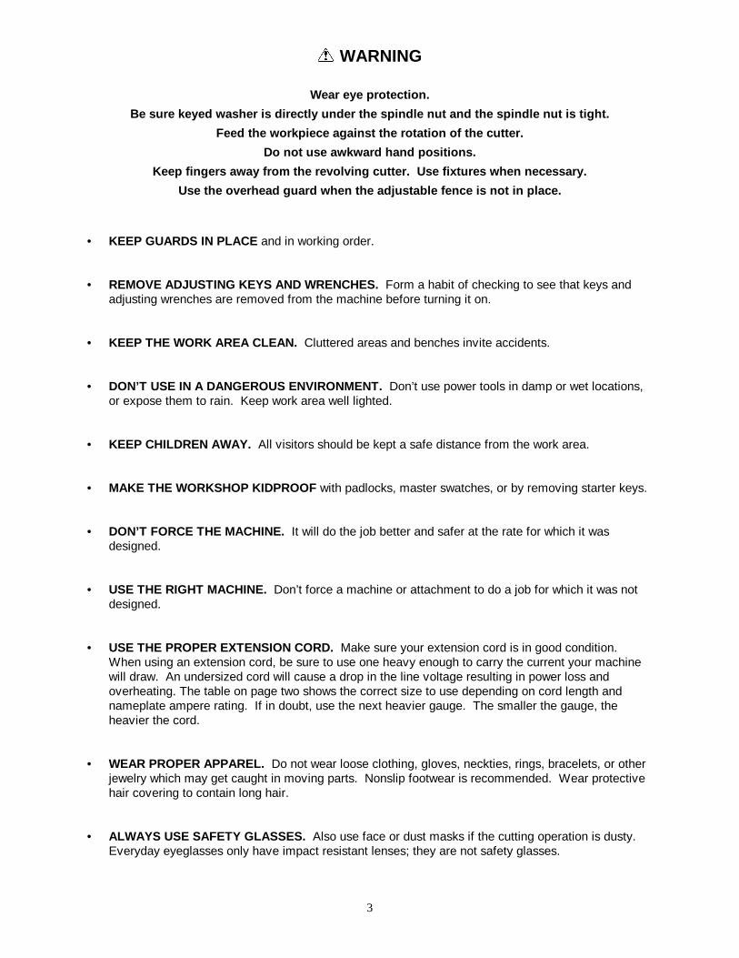
� WARNING
Wear eye protection.
Be sure keyed washer is directly under the spindle nut and the spindle nut is tight.
Feed the workpiece against the rotation of the cutter.
Do not use awkward hand positions.
Keep fingers away from the revolving cutter. Use fixtures when necessary.
Use the overhead guard when the adjustable fence is not in place.
• KEEP GUARDS IN PLACE and in working order.
• REMOVE ADJUSTING KEYS AND WRENCHES. Form a habit of checking to see that keys andadjusting wrenches are removed from the machine before turning it on.
• KEEP THE WORK AREA CLEAN. Cluttered areas and benches invite accidents.
• DON’T USE IN A DANGEROUS ENVIRONMENT. Don’t use power tools in damp or wet locations,or expose them to rain. Keep work area well lighted.
• KEEP CHILDREN AWAY. All visitors should be kept a safe distance from the work area.
• MAKE THE WORKSHOP KIDPROOF with padlocks, master swatches, or by removing starter keys.
• DON’T FORCE THE MACHINE. It will do the job better and safer at the rate for which it wasdesigned.
• USE THE RIGHT MACHINE. Don’t force a machine or attachment to do a job for which it was notdesigned.
• USE THE PROPER EXTENSION CORD. Make sure your extension cord is in good condition.When using an extension cord, be sure to use one heavy enough to carry the current your machinewill draw. An undersized cord will cause a drop in the line voltage resulting in power loss andoverheating. The table on page two shows the correct size to use depending on cord length andnameplate ampere rating. If in doubt, use the next heavier gauge. The smaller the gauge, theheavier the cord.
• WEAR PROPER APPAREL. Do not wear loose clothing, gloves, neckties, rings, bracelets, or otherjewelry which may get caught in moving parts. Nonslip footwear is recommended. Wear protectivehair covering to contain long hair.
• ALWAYS USE SAFETY GLASSES. Also use face or dust masks if the cutting operation is dusty.Everyday eyeglasses only have impact resistant lenses; they are not safety glasses.

4
• SECURE WORK. Use clamps or a vise to hold work when practical. It’s safer than using your handand it frees both hands to operate the tool.
• DON’T OVERREACH. Keep proper footing and balance at all times.
• MAINTAIN TOOLS WITH CARE. Keep tools sharp and clean for best and safest performance.Follow instructions for lubricating and changing accessories.
• ALWAYS DISCONNECT THE MACHINE FROM THE POWER SOURCE BEFORE SERVICING.
• REDUCE THE RISK OF UNINTENTIONAL STARTING. Make sure the switch is in the off positionbefore plugging in.
• USE REOMMENDED ACCESSORIES. Consult the operator’s manual for recommendedaccessories. The use of improper accessories may cause risk of injury to persons.
• NEVER STAND ON A MACHINE. Serious injury could occur if the machine tipped of if the blade isunintentionally contacted.
• CHECK DAMAGED PARTS. Before further use of the machine, a guard or other part that isdamaged should be carefully checked to determine that it will operate properly and perform itsintended function - check for alignment of moving parts, binding of moving parts, breakage of parts,mounting, and any other conditions that may affect its operation. A guard or other part that isdamaged should be properly repaired or replaced.
• DIRECTION OF FEED. Feed work into the cutter against the direction of rotation of the cutter only.
• NEVER LEAVE THE MACHINE RUNNING UNATTENDED. TURN POWER OFF. Don’t leave themachine until it comes to a complete stop.
Volts Total Length of Cord in Feet
240V 50 100 200 300
AWG14 12 Not Recommended

5
Specifications: JWS-25CS
Stock Number................................................................................................................................ 708322Spindle Speeds ........................................................................................................ 8,000 & 10,000 RPMTable Size ...................................................................................................................................25" x 25”Table T-Slot..................................................................................................................... 3/8" x 3/4" T-slotTable Opening Diameter.........................................................................................................................7"Insert Opening Diameter...................................................................................................1 5/8”, 3", 3 1/2"Fence Size (2) ..................................................................................................................... 9 1/2" x 2 3/4"Spindle Size ............................................................................................................................. 1/2" & 3/4"Under Nut Capacity .................................................................................................. (1/2") 2 3/4", (3/4”) 3”Spindle Travel ........................................................................................................................................3"Table Height .........................................................................................................................................34"Overall Dimensions ................................................................................................... 26”W x 26"D x 44"HDust Chute Diameter ..............................................................................................................................4"Motor...................................................................................................................... 3 HP, 1Ph, 230V OnlyNet Weight (approx.) .....................................................................................................................320 lbs.Shipping Weight (approx.) .............................................................................................................340 lbs.
Table of Contents Page #
Warranty .................................................................................................................................................2Warnings..............................................................................................................................................3-4Specifications ..........................................................................................................................................5Table of Contents ....................................................................................................................................5Unpacking & Cleanup ..............................................................................................................................6Contents of Shipping Container ...............................................................................................................6Assembly.................................................................................................................................................7Electrical Connections .............................................................................................................................8Electrical Controls....................................................................................................................................8Spindle Installation & Removal ................................................................................................................8Belt Adjustment .......................................................................................................................................9Speed Change.........................................................................................................................................9Squaring the Fence .................................................................................................................................9Fence Adjustment.................................................................................................................................. 10Changing Cutters................................................................................................................................... 10Table Ring Removal and Installation ..................................................................................................... 11Spindle Control ...................................................................................................................................... 11Using the Fence as a Guide.............................................................................................................. 11-12Shaping with Collars and Starting Pin .................................................................................................... 12Collar Positioning................................................................................................................................... 13Starting Pin............................................................................................................................................ 13Troubleshooting................................................................................................................................ 14-15Parts Breakdowns & Parts Lists ........................................................................................................ 16-23Wiring Diagram ..................................................................................................................................... 24
The specifications in this manual are given as general information and are not binding. JET Equipmentand Tools reserves the right to effect, at any time and without prior notice, changes or alterations toparts, fittings, and accessory equipment deemed necessary for any reason whatsoever.

6
Unpacking and Cleanup
1. Finish removing all contents from theshipping container. Do not discard anyshipping material until the shaper is set upand running.
2. Inspect contents for shipping damage andreport any damage to your distributor.
3. Clean all protected parts with kerosene. Donot use gasoline, paint thinner, or anycellulose-based solvent. These will damagepainted surfaces and melt plastic.
Contents of the Shipping Container
1. Shaper
Box 11. Dust Chute2. Ratcheting Handles2. Handwheel Handles2. 1/2" & 3/4"Spindles2. Knobs2. Washers1. Draw Bar & Nut1. Spindle Guard Assembly1. Arbor Wrench1. Open End Wrench
Box 22. Fence Assemblies1. Miter Gauge Assembly2. Angle Hex Wrenches2. Hold-down Assemblies1. Starting Pin (not shown)
Box 31. Extension Wing (not shown)
Box 41. Rear Door (not shown)2. Pins (not shown)
7
Assembly
1. Attach table extension wing to the shapertable using three hex cap bolts and threewashers.
2. Attach the rear door to the shaper cabinetusing two pins.
3. Attach the chrome handle to the raising andlowering handwheel located on the front ofthe machine.
4. Attach the plastic handle to the motorbracket plate.
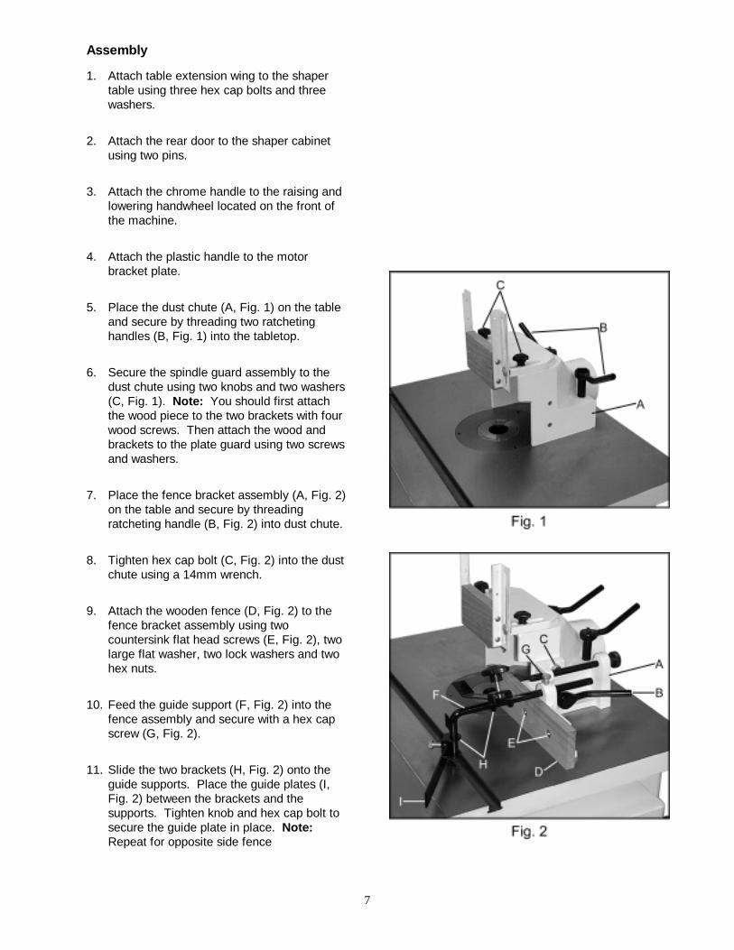
5. Place the dust chute (A, Fig. 1) on the tableand secure by threading two ratchetinghandles (B, Fig. 1) into the tabletop.
6. Secure the spindle guard assembly to thedust chute using two knobs and two washers(C, Fig. 1). Note: You should first attachthe wood piece to the two brackets with fourwood screws. Then attach the wood andbrackets to the plate guard using two screwsand washers.
7. Place the fence bracket assembly (A, Fig. 2)on the table and secure by threadingratcheting handle (B, Fig. 2) into dust chute.
8. Tighten hex cap bolt (C, Fig. 2) into the dustchute using a 14mm wrench.
9. Attach the wooden fence (D, Fig. 2) to thefence bracket assembly using twocountersink flat head screws (E, Fig. 2), twolarge flat washer, two lock washers and twohex nuts.
10. Feed the guide support (F, Fig. 2) into thefence assembly and secure with a hex capscrew (G, Fig. 2).
11. Slide the two brackets (H, Fig. 2) onto theguide supports. Place the guide plates (I,Fig. 2) between the brackets and thesupports. Tighten knob and hex cap bolt tosecure the guide plate in place. Note:Repeat for opposite side fence

8
Electrical Connections
� WARNINGAll electrical connections must be done by a
qualified electrician!Failure to comply may cause serious injury
and/or damage to property!
The JWS-25CS is rated at 230V single phaseonly. The machine must be properly grounded.
Electrical Controls
The shaper is equipped with a push-buttoncontrol system and reversing switch. The greenstart and red stop push buttons are mounted in acontrol enclosure on the front of the machine.
To reverse the rotation of the spindle, shut offthe motor, allow motor to come to a completestop, and rotate the reversing switch.
Spindle Installation and Removal
� WARNINGAll adjustments to the machine must bemade with the power off and unplugged
from the power source!Failure to comply may result in serious
injury!
To install:1. The shaper comes with a 1/2" and 3/4"
spindle assembly.
2. Raise the spindle fully by turning handwheelclockwise.
3. Clean the spindle and spindle housing.
4. Place the spindle into the spindle housingand line up the cut out portion of the spindlewith the raised section of the spindlehousing.
5. Completely thread the drawbar (Fig. 4) intothe spindle through the bottom of the mainspindle housing.
6. Tighten the drawbar nut (B, Fig. 4) whileholding the spindle nut, or spindle flat (A,Fig. 3). Make sure the left hand threadsafety lock nut is installed above the spindlenut, and tightened.
To remove:1. Raise the spindle fully.
2. Remove two knobs that hold the guardassembly to the dust chute. Place anadjustable wrench on the spindle nut, orspindle flat (A, Fig. 3).
3. Loosen the draw bar nut (B, Fig. 4) with a14mm wrench, and tap upward lightly with ablock of wood to break the spindle loose.
4. Finish removing the draw bar and lift out thespindle from the top.

9
Belt Adjustment
� WARNING
All adjustments to the machine must bemade with the power off and unplugged
from the power source!Failure to comply may result in serious
injury!
Check the drive belt to insure that the pulleysare accurately aligned. If alignment is required,loosen the setscrew (A, Fig. 5) in the motorpulley and reposition the pulley on the motorshaft.
Speed Change
The JWS-25CS shaper may be operated at8,000 RPM (lower pulleys) or 10,000 RPM(upper pulleys). To change the spindle speed,loosen the lock handle (B, Fig. 5) and pivot themotor assembly toward the spindle. Repositionthe belt to the desired speed and tension thebelt.
Squaring the Fence
Periodically the wood fence will have to besquared with the mounting surface and adjustedparallel to each other. To correct, do thefollowing:
1. Check the two ratcheting handles (A, Fig. 6)holding the fence assembly to the table andmake sure they are tight.
2. Check the four countersink flat head screws(B, Fig. 6) that secure the wooden fencesand make sure they are tight.
3. Take a 2x4 with a jointed edge and clamp itto the shaper table making sure the jointededge is absolutely on line with the mitergroove and close to the fence as shown infigure 6.
4. Loosen the two lock handles (C, Fig. 6) andturn the fence adjustment knobs (D, Fig. 6)to move both fences against the jointededge of the 2x4. After this adjustment thefences should make flush contact with thejointed edge and square with the table.
Note: Periodically the wooden fences mayrequire resurfacing in order to remainparallel and square with the table.
10
Fence Adjustments
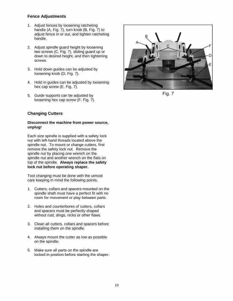
1. Adjust fences by loosening ratchetinghandle (A, Fig. 7), turn knob (B, Fig. 7) toadjust fence in or out, and tighten ratchetinghandle.
2. Adjust spindle guard height by looseningtwo screws (C, Fig. 7), sliding guard up ordown to desired height, and then tighteningscrews.
3. Hold down guides can be adjusted byloosening knob (D, Fig. 7).
4. Hold in guides can be adjusted by looseninghex cap screw (E, Fig. 7).
5. Guide supports can be adjusted byloosening hex cap screw (F, Fig. 7).
Changing Cutters
Disconnect the machine from power source,unplug!
Each size spindle is supplied with a safety locknut with left-hand threads located above thespindle nut. To mount or change cutters, firstremove the safety lock nut. Remove thespindle nut by placing one wrench on thespindle nut and another wrench on the flats ontop of the spindle. Always replace the safetylock nut before operating shaper.
Tool changing must be done with the utmostcare keeping in mind the following points.
1. Cutters, collars and spacers mounted on thespindle shaft must have a perfect fit with noroom for movement or play between parts.
2. Holes and counterbores of cutters, collarsand spacers must be perfectly shapedwithout rust, dings, nicks or other flaws.
3. Clean all cutters, collars and spacers beforeinstalling them on the spindle.
4. Always mount the cutter as low as possibleon the spindle.
5. Make sure all parts on the spindle arelocked in position before starting the shaper.

11
Table Ring Removal and Installation
Disconnect the machine from power source,unplug!
The rings should easily lift out of the tableinsert. The table insert has three setscrews thatcan raise and lower the insert. The insertshould be slightly lower than the table. Keepthe rings and insert clean to prevent them fromsticking. If the rings are difficult to remove fromthe insert:
1. Remove any collet or spindle assembly inthe spindle.
2. Lower the spindle assembly.
3. Place a scrap of piece of wood between thering to be removed and the spindle.
4. Raise the spindle until the ring lifts out.
5. Clean rings and insert thoroughly.
Operation
Spindle Control
To raise or lower spindle:
1. Loosen spindle lock handwheel found onthe left side of the cabinet.
2. Raise or lower spindle to desired height byturning handwheel found on the front sideof the cabinet. There is an indicator scalefound by the handwheel, which will aid withraising and lowering measurements.
3. Tighten spindle lock handwheel.
Using the Fence as a Guide
Shaping with the fence is the safest and mostsatisfactory method of working. This methodshould always be used when work permits.Almost all-straight work can be used with thefence.
1. For most work, where a portion of the edgeof the work is not touched by the cutter,both the front and rear fences are in astraight line, as shown in figure 8.

12
2. When the shaping operation removes theentire edge of the work (i.e. jointing ormaking a full bead), the shaped edge willnot be supported by the rear fence whenboth fences are in line as shown in Figure 9.In this case, the work piece should beadvanced to the position shown in figure 9and stopped.
3. The rear fence should be advanced tocontact the work as shown in figure 10. Therear fence will then be in line with thecutting circle.
Shaping with Collars and Starting Pin
Follow these rules when shaping with collarsand starting pin for safest operation and bestresults:
1. Collars must be smooth and free from allgum or other substances.
2. The edge of the work must be smooth. Anyirregularity in the surface, which ridesagainst the collar, will be duplicated on theshaped surface.
3. A portion of the work's edge must remainuntouched by the cutter so that the collarwill have sufficient bearing surface. Seefigure 11 for an example of insufficientbearing surface.
4. Figure 12 illustrates sufficient bearingsurface.
5. Under no circumstances should a smallworkpiece be shaped against the collarsas shown in Figure 13.
13
Collar Positioning
Collars may be positioned above, below, orbetween two cutters:
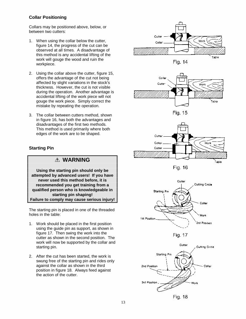
1. When using the collar below the cutter,figure 14, the progress of the cut can beobserved at all times. A disadvantage ofthis method is any accidental lifting of thework will gouge the wood and ruin theworkpiece.
2. Using the collar above the cutter, figure 15,offers the advantage of the cut not beingaffected by slight variations in the stock'sthickness. However, the cut is not visibleduring the operation. Another advantage isaccidental lifting of the work piece will notgouge the work piece. Simply correct themistake by repeating the operation.
3. The collar between cutters method, shownin figure 16, has both the advantages anddisadvantages of the first two methods.This method is used primarily where bothedges of the work are to be shaped.
Starting Pin
� WARNING
Using the starting pin should only beattempted by advanced users! If you have
never used this method before, it isrecommended you get training from a
qualified person who is knowledgeable instarting pin shaping!
Failure to comply may cause serious injury!
The starting pin is placed in one of the threadedholes in the table:
1. Work should be placed in the first positionusing the guide pin as support, as shown infigure 17. Then swing the work into thecutter as shown in the second position. Thework will now be supported by the collar andstarting pin.
2. After the cut has been started, the work isswung free of the starting pin and rides onlyagainst the collar as shown in the thirdposition in figure 18. Always feed againstthe action of the cutter.
14
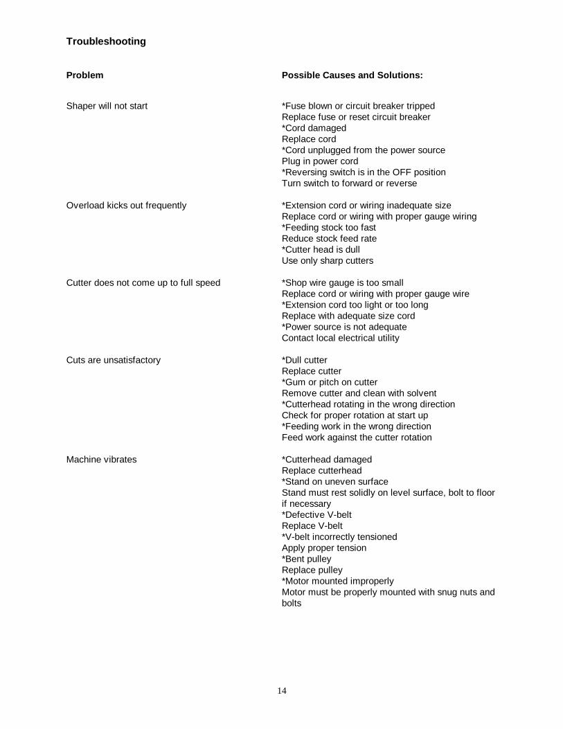
Troubleshooting
Problem Possible Causes and Solutions:
Shaper will not start *Fuse blown or circuit breaker trippedReplace fuse or reset circuit breaker*Cord damagedReplace cord*Cord unplugged from the power sourcePlug in power cord*Reversing switch is in the OFF positionTurn switch to forward or reverse
Overload kicks out frequently *Extension cord or wiring inadequate sizeReplace cord or wiring with proper gauge wiring*Feeding stock too fastReduce stock feed rate*Cutter head is dullUse only sharp cutters
Cutter does not come up to full speed *Shop wire gauge is too smallReplace cord or wiring with proper gauge wire*Extension cord too light or too longReplace with adequate size cord*Power source is not adequateContact local electrical utility
Cuts are unsatisfactory *Dull cutterReplace cutter*Gum or pitch on cutterRemove cutter and clean with solvent*Cutterhead rotating in the wrong directionCheck for proper rotation at start up*Feeding work in the wrong directionFeed work against the cutter rotation
Machine vibrates *Cutterhead damagedReplace cutterhead*Stand on uneven surfaceStand must rest solidly on level surface, bolt to floorif necessary*Defective V-beltReplace V-belt*V-belt incorrectly tensionedApply proper tension*Bent pulleyReplace pulley*Motor mounted improperlyMotor must be properly mounted with snug nuts andbolts

15
Edge splits off on cross grain cut *Characteristic of this type of cutMake cross grain cuts first, then finish cut with thegrainUse scrap block to support end of cut
Raised areas on shaped edge *Variation of pressure holding work against cutterHold work firmly against table and fenceUse holddowns
Work pulled from hand *Feeding work in the wrong directionAlways feed work against the rotation of thecutterhead
Depth of cut not uniform *Fence misalignmentAlign outfeed fence*Side pressure not uniformUse holddowns; keep constant pressure againstfence
Work burns *Cutting too deep on one passOn hardwoods take light cuts; attain full depth withseveral passes*Forcing workFeed work slowly and steadily
Cut height not uniform *Variation in pressure holding work to tableKeep pressure firm throughout passUse holddownsMake pass slowly and steadilyKeep work under cutter whenever possible
Cuts not smooth *Wrong R.P.M.Use faster speed*Feeding too fastSlow feed speed*Working against the grainWork with the grain whenever possible*Cutting too deep on one passTake several passes on very deep cuts
Spindle does not raise freely *Sawdust or dirt in raising mechanismBrush or blow out dirt and saw dust

16
Base Breakdown

17
Parts List for the JET JWS-25CS Shaper
Base AssemblyIndex PartNo. No. Description Size Qty.
1..........JWS25-101...................... Cabinet.......................................................... .................................12..........JWS25-102...................... JET Stripe ..................................................... .................................13..........JWS25-103...................... Plastic Nut..................................................... .................................14..........JWS25-104...................... Strain Relief .................................................. .................................15..........JWS25-105...................... Motor Cord (fwd.-rev. switch to motor)........... .................................16..........JWS25-106...................... Screw............................................................ 3/16x3/4 ...................27..........JWS25-107...................... Hex Head Bolt ............................................... M8x75 ......................28..........JWS25-108...................... Spring............................................................ .................................29..........TS-0680031 ..................... Washer.......................................................... 5/16 ..........................410........TS-0720091 ..................... Lock Washer ................................................. 3/8 ..........................1111........TS-0680041 ..................... Flat Washer................................................... 3/8 ..........................1212........TS-0060051 ..................... Hex Head Screw............................................ 3/8-16x1 ...................813........JWS25-113...................... Bar ................................................................ .................................214........JWS25-114...................... Knob.............................................................. .................................215........JWS25-115...................... Motor Door .................................................... .................................116........JWS25-116...................... I.D. Label....................................................... .................................117........JWS25-117...................... Door Pin ........................................................ .................................418........JWS25-118...................... Cabinet Door ................................................. .................................119........TS-0561031 ..................... Hex Nut ......................................................... 3/8-16.......................420........JWS25-120...................... Table............................................................. .................................121........JWS25-121...................... Table Insert ................................................... .................................122........JWS25-122-1................... Table Ring..................................................... .................................123........JWS25-123-2................... Table Ring..................................................... .................................124........TS-0270061 ..................... Socket Set Screw .......................................... 5/16-18x5/8 ..............325........709520............................. Miter Gauge Assembly (incls. 25-1 – 25-8) .... .................................125-1.....TS-0680031 ..................... Flat Washer................................................... 5/16 ..........................125-2.....JWS25-125-2................... Miter Gauge Body ......................................... .................................125-3.....JWS25-125-3................... Washer.......................................................... .................................125-4.....JWS25-125-4................... Flat Head Screw............................................ .................................125-5.....JWS25-125-5................... Knob.............................................................. .................................125-6.....JWS25-125-6................... Screw............................................................ 3/16x1/4 ...................125-7.....JWS25-125-7................... Pointer........................................................... .................................125-8.....JWS25-125-8................... Guide Plate ................................................... .................................126........JWS25-126...................... Label (spindle lock)........................................ .................................127........TS-0060051 ..................... Hex Head Bolt ............................................... 3/8-16x1 ...................328........JWS25-128...................... Extension Wing ............................................. .................................129........JWS25-129...................... Label (spindle direction)................................. .................................130........JWS25-130...................... Scale............................................................. .................................131........JWS25-131...................... Warning Label ............................................... .................................132........JWS25-132...................... Strain Relief Bushing..................................... .................................233........JWS25-133...................... Power Cord ................................................... .................................134........JWS25-134...................... Name Plate ................................................... .................................135........JWS25-135...................... Hex Nut ......................................................... .................................436........JWS25-136...................... Fwd.-Rev. Switch Assembly .......................... .................................137........JWS25-137...................... Screw............................................................ 5/32x4 ......................238........JWS25-138...................... Flat Head Screw............................................ 5/32x3/4 ...................239........JWS25-139...................... Switch Cover ................................................. .................................140........JWS25-140...................... Magnetic Switch Assembly ............................ .................................141........JWS25-141...................... Switch Cord (for.-rev. switch to magnetic switch ..............................142........JWS25-142...................... Starting Pin ................................................... .................................1

18
Motor Assembly
19
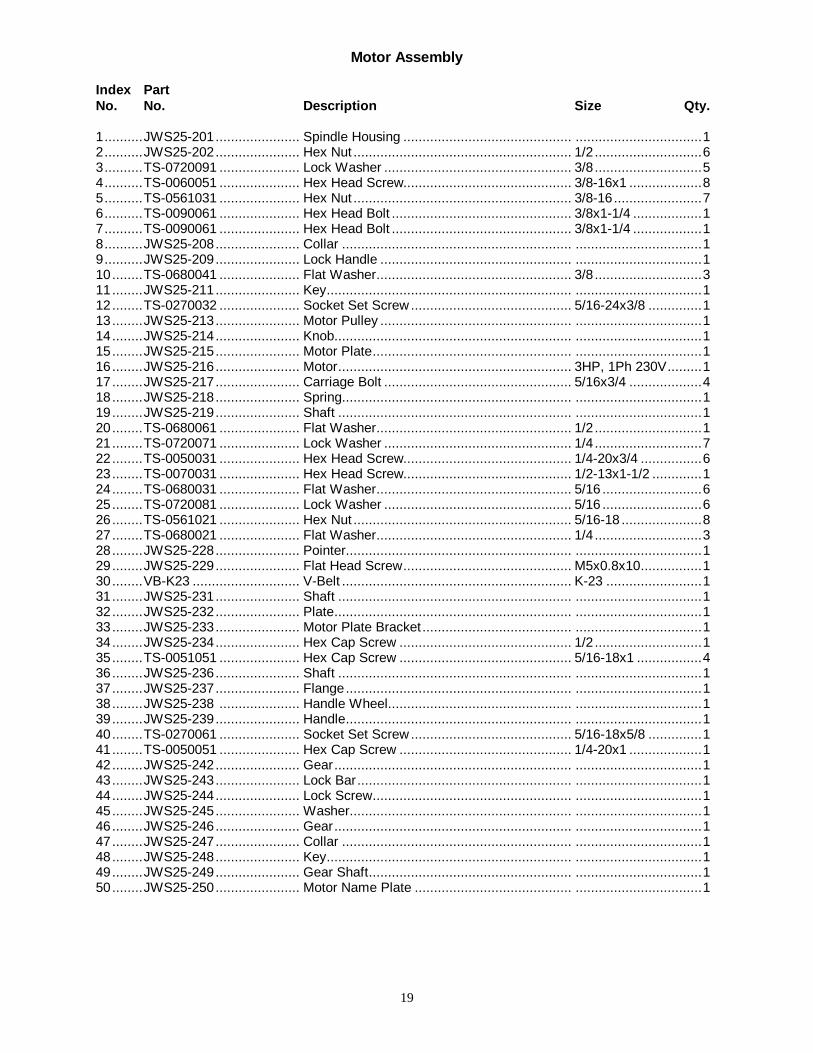
Motor Assembly
Index PartNo. No. Description Size Qty.
1..........JWS25-201...................... Spindle Housing ............................................ .................................12..........JWS25-202...................... Hex Nut ......................................................... 1/2 ............................63..........TS-0720091 ..................... Lock Washer ................................................. 3/8 ............................54..........TS-0060051 ..................... Hex Head Screw............................................ 3/8-16x1 ...................85..........TS-0561031 ..................... Hex Nut ......................................................... 3/8-16.......................76..........TS-0090061 ..................... Hex Head Bolt ............................................... 3/8x1-1/4 ..................17..........TS-0090061 ..................... Hex Head Bolt ............................................... 3/8x1-1/4 ..................18..........JWS25-208...................... Collar ............................................................ .................................19..........JWS25-209...................... Lock Handle .................................................. .................................110........TS-0680041 ..................... Flat Washer................................................... 3/8 ............................311........JWS25-211...................... Key................................................................ .................................112........TS-0270032 ..................... Socket Set Screw .......................................... 5/16-24x3/8 ..............113........JWS25-213...................... Motor Pulley .................................................. .................................114........JWS25-214...................... Knob.............................................................. .................................115........JWS25-215...................... Motor Plate.................................................... .................................116........JWS25-216...................... Motor............................................................. 3HP, 1Ph 230V.........117........JWS25-217...................... Carriage Bolt ................................................. 5/16x3/4 ...................418........JWS25-218...................... Spring............................................................ .................................119........JWS25-219...................... Shaft ............................................................. .................................120........TS-0680061 ..................... Flat Washer................................................... 1/2 ............................121........TS-0720071 ..................... Lock Washer ................................................. 1/4 ............................722........TS-0050031 ..................... Hex Head Screw............................................ 1/4-20x3/4 ................623........TS-0070031 ..................... Hex Head Screw............................................ 1/2-13x1-1/2 .............124........TS-0680031 ..................... Flat Washer................................................... 5/16 ..........................625........TS-0720081 ..................... Lock Washer ................................................. 5/16 ..........................626........TS-0561021 ..................... Hex Nut ......................................................... 5/16-18 .....................827........TS-0680021 ..................... Flat Washer................................................... 1/4 ............................328........JWS25-228...................... Pointer........................................................... .................................129........JWS25-229...................... Flat Head Screw............................................ M5x0.8x10................130........VB-K23 ............................ V-Belt ............................................................ K-23 .........................131........JWS25-231...................... Shaft ............................................................. .................................132........JWS25-232...................... Plate.............................................................. .................................133........JWS25-233...................... Motor Plate Bracket ....................................... .................................134........JWS25-234...................... Hex Cap Screw ............................................. 1/2 ............................135........TS-0051051 ..................... Hex Cap Screw ............................................. 5/16-18x1 .................436........JWS25-236...................... Shaft ............................................................. .................................137........JWS25-237...................... Flange........................................................... .................................138........JWS25-238 ..................... Handle Wheel................................................ .................................139........JWS25-239...................... Handle........................................................... .................................140........TS-0270061 ..................... Socket Set Screw .......................................... 5/16-18x5/8 ..............141........TS-0050051 ..................... Hex Cap Screw ............................................. 1/4-20x1 ...................142........JWS25-242...................... Gear.............................................................. .................................143........JWS25-243...................... Lock Bar........................................................ .................................144........JWS25-244...................... Lock Screw.................................................... .................................145........JWS25-245...................... Washer.......................................................... .................................146........JWS25-246...................... Gear.............................................................. .................................147........JWS25-247...................... Collar ............................................................ .................................148........JWS25-248...................... Key................................................................ .................................149........JWS25-249...................... Gear Shaft..................................................... .................................150........JWS25-250...................... Motor Name Plate ......................................... .................................1

20
Spindle Assembly
21
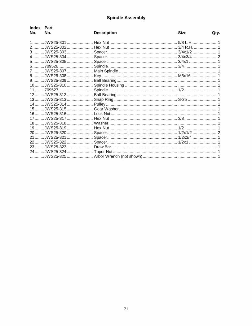
Spindle Assembly
Index PartNo. No. Description Size Qty.
1..........JWS25-301...................... Hex Nut ......................................................... 5/8 L.H......................12..........JWS25-302...................... Hex Nut ......................................................... 3/4 R.H. ....................13..........JWS25-303...................... Spacer........................................................... 3/4x1/2 .....................14..........JWS25-304...................... Spacer........................................................... 3/4x3/4 .....................25..........JWS25-305...................... Spacer........................................................... 3/4x1 ........................16..........709526............................. Spindle.......................................................... 3/4 ............................17..........JWS25-307...................... Main Spindle ................................................. .................................18..........JWS25-308...................... Key................................................................ M5x16 ......................19..........JWS25-309...................... Ball Bearing................................................... .................................110........JWS25-310...................... Spindle Housing ............................................ .................................111........709527............................. Spindle.......................................................... 1/2 ............................112........JWS25-312...................... Ball Bearing................................................... .................................113........JWS25-313...................... Snap Ring ..................................................... S-25 .........................114........JWS25-314...................... Pulley ............................................................ .................................115........JWS25-315...................... Gear Washer................................................. .................................116........JWS25-316...................... Lock Nut........................................................ .................................117........JWS25-317...................... Hex Nut ......................................................... 3/8 ............................118........JWS25-318...................... Washer.......................................................... .................................119........JWS25-319...................... Hex Nut ......................................................... 1/2 ............................120........JWS25-320...................... Spacer........................................................... 1/2x1/2 .....................221........JWS25-321...................... Spacer........................................................... 1/2x3/4 .....................122........JWS25-322...................... Spacer........................................................... 1/2x1 ........................123........JWS25-323...................... Draw Bar ....................................................... .................................124........JWS25-324...................... Taper Nut ...................................................... .................................1............JWS25-325...................... Arbor Wrench (not shown) ............................. .................................1
22
Fence Breakdown

23
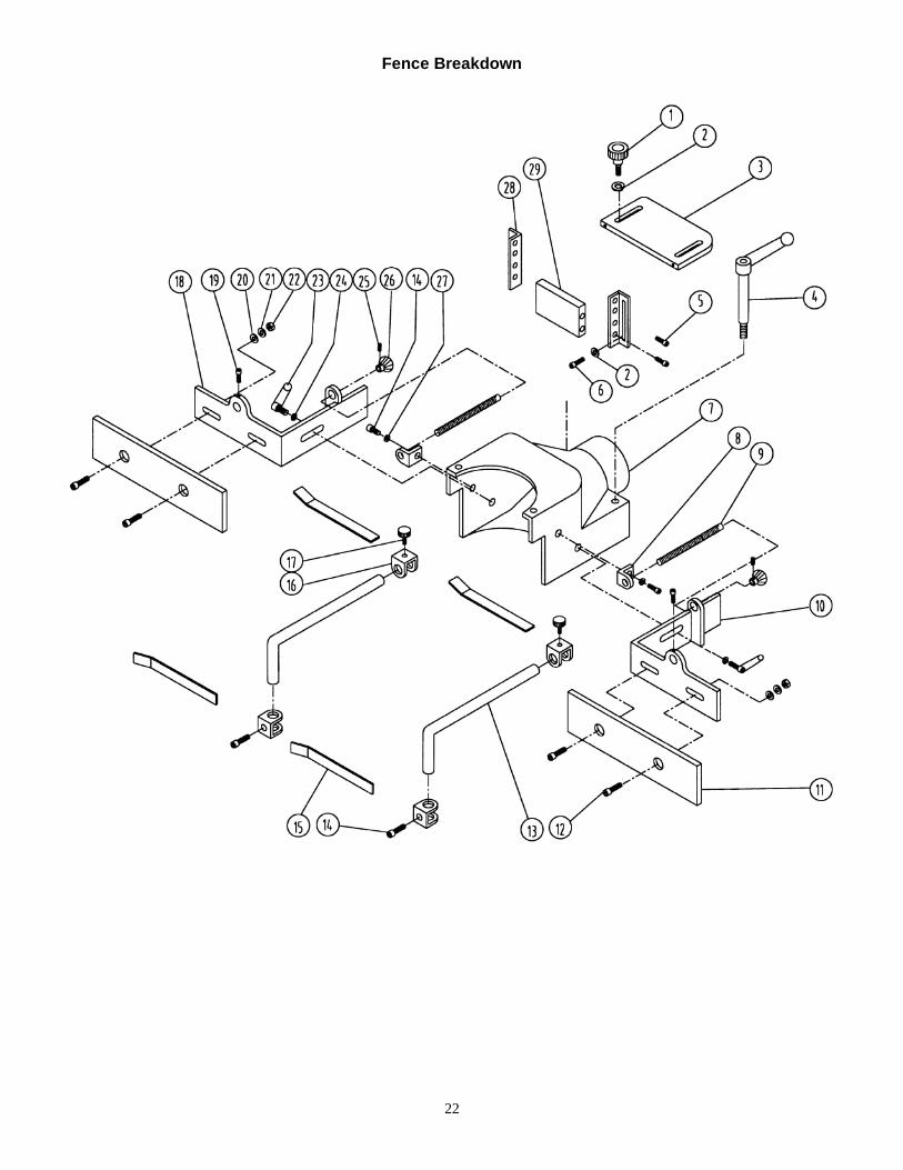
Fence Assembly
Index PartNo. No. Description Size Qty.
1..........JWS25-401...................... Knob.............................................................. .................................22..........TS-0680021 ..................... Flat Washer................................................... 1/4 ............................43..........JWS25-403...................... Plate Guard................................................... .................................14..........JWS25-404...................... Ratcheting Handle......................................... .................................25..........JWS25-405...................... Wood Screw.................................................. .................................46..........JWS25-406...................... Screw............................................................ 1/4-20x1/2 ................27..........JWS25-407...................... Dust Chute .................................................... .................................18..........JWS25-408...................... Bracket Screw Guide..................................... .................................29..........JWS25-409...................... Screw Guide.................................................. .................................210........JWS25-410...................... Bracket Fence R.H. ....................................... .................................111........JWS25-411...................... Fence............................................................ .................................2............709529............................. Fence Assembly............................................ ...................................12........JWS25-412...................... Flat Head Screw............................................ 5/16x1-1/2 ................413........JWS25-413...................... Guide Support ............................................... .................................214........TS-0060051 ..................... Hex Cap Bolt ................................................. 3/8-16x1 ...................415........JWS25-415...................... Guide Plate ................................................... .................................4............709522............................. Work Hold Down ........................................... ...................................16........JWS25-416...................... Slide Block .................................................... .................................417........JWS25-417...................... Knob.............................................................. .................................218........JWS25-418...................... Bracket Fence L.H......................................... .................................119........JWS25-419...................... Hex Head Bolt ............................................... 3/8x3/4 .....................220........TS-0680031 ..................... Flat Washer................................................... 5/16 ..........................421........TS-0720081 ..................... Lock Washer ................................................. 5/16 ..........................422........TS-0561021 ..................... Hex Nut ......................................................... 5/16-18 .....................423........JWS25-423...................... Ratcheting Handle......................................... .................................224........TS-0680041 ..................... Flat Washer................................................... 3/8 ............................225........TS-0267021 ..................... Socket Set Screw .......................................... 1/4x1/4 .....................226........JWS25-426...................... Knob.............................................................. .................................227........TS-0720091 ..................... Lock Washer ................................................. 3/8 ............................228........JWS25-428...................... Angle Fence .................................................. .................................229........JWS25-429...................... Guard............................................................ .................................1
Optional Accessories709529 Fence Assembly709528 Hardware Kit709527 1/2" Spindle709526 3/4" Spindle709525 1/2" Router Collet709524 1/4" Router Collet709523 3/8" Router Collet709522 Work Hold Down709521 1” Spindle709520 Miter Gauge

24
Electrical Schematic