Embed Size (px)
Citation preview

Rh
T E C H N I C A L W H I T E P A P E R
N O V E M B E R 2 0 1 6
V 2 . 1
Transatomic Power’s advanced molten salt reactor unlocks clean, safe, and low-cost nuclear energy. Our revolutionary design
allows us to achieve a high fuel burnup in a compact system, solve the nuclear industry’s most pressing problems, and clear the
way for advanced nuclear power’s global deployment.
T R A N S A T O M I C

C O N T E N T S
Executive Summary 1
Overview 2
1 / Introduction 3
1.1 – Molten Salt Reactors 3
1.2 – What’s New Here? 3
2 / Reactor Description and Design Considerations 6
2.1 – Nuclear Island Rendering and Schematic 6
2.2 – Liquid Fuel vs. Solid Fuel 7
2.3 – Salt Formulation 12
2.4 – Zirconium Hydride Moderator 13
2.5 – Material Stability 15
2.6 – Neutronics, Fuel Capacity, and Waste Stream 16
3 / Better Inherent Safety 20
3.1 – Self-Stabilizing Core 20
3.2 – Smaller Inventory of Radionuclides 20
3.3 – Reduced Driving Force 21
3.4 – Inherent Safety 22
4 / Reactor Cost 24
5 / Anti-Proliferation Analysis 26
6 / Why Not Thorium First? 27
7 / Future TAP Designs 28
8 / Conclusions 29
References 30
Appendix A: Moderator Stability 33
About Transatomic Power 36

1
E X E C U T I V E S U M M A R Y
Transatomic Power is developing an advanced molten salt reactor that generates clean, passively safe, proliferation-resistant, and low-cost nuclear power. This reactor can consume the same 5% enriched uranium used in commercial light water reactors, while achieving more than twice the burnup and resulting in a greater than 50% reduction in annual long-lived waste production.
Key characteristics of a first commercial plant are as follows:
Reactor Type Molten Salt Reactor
Fuel 5% low-enriched uranium
Fuel Salt LiF-(Act)F4
Moderator Zirconium Hydride (ZrH1.66)
Neutron Spectrum Thermal/Epithermal
Thermal Capacity 1250 MWth
Gross Electric Capacity 550 MWe
Net Electric Capacity 520 MWe
Outlet Temperature 650ºC
Gross Thermal Efficiency 44% using steam cycle with reheat
Long-lived Actinide Waste Less than 50% that of an LWR
Station Blackout Safety Walkaway safe without outside intervention
Overnight Cost $2 billion
Mode of Operation Typically for base load; may be used for load-following
Designers Transatomic Power Corporation

2
O V E R V I E W
Section 1 of this white paper briefly reviews the molten salt reactor (MSR) concept and explains the key technology innovations in the Transatomic Power (TAP) MSR design. Section 2 describes the reactor itself – including the nuclear island layout, fuel composition, moderator, materials, and the system’s neutronics and waste stream – and examines the technology in more detail. The next sections focus on the benefits that this new design enables: Section 3 discusses improved inherent safety, Section 4 describes the lower cost, and Section 5 analyzes the anti-proliferation benefits.
In Section 6, we explain why we chose this design pathway instead of a thorium-fueled reactor. Section 7 describes likely future advances to the reactor design and the benefits these will enable. Section 8, the conclusion, summarizes our analysis.
V E R S I O N N O T E
This version of the TAP design white paper incorporates multiple revisions based on further research performed over the past year on both the design’s reactor physics and reactor plant materials. Consistent with the scientific process, this work has revealed new understandings about the system and necessitated updates to earlier results.
Specifically, we have realized that our initial analyses of spent nuclear fuel (SNF) core loadings were centered around inaccurate assumptions about reactor behavior that, upon detailed review, had to be corrected. This led to the conclusion that while the reactor can achieve criticality on an SNF fuel load and an SNF fuel feed, it cannot maintain criticality for sufficient lengths of time to produce a sustainable net-negative waste profile.
The results have prompted a shift in focus to reducing the rate at which waste is produced while simultaneously utilizing the current commercial 5% LEU supply chain. Our new work has shown significant reductions in waste generation compared to large LWRs, and the TAP reactor is one of the only advanced reactor designs to accomplish this using 5% enriched fuel.
The TAP reactor is therefore still a cleaner, safer, and potentially lower-cost solution to the industry’s challenges, and we continue to develop the plant design keeping these points in mind.

3
1 I N T R O D U C T I O N
1 . 1 M O L T E N S A L T R E A C T O R S
Molten salt reactors have long interested the nuclear engineering community because of their many safety benefits (passive shutdown ability, low pressure piping, negative void and temperature coefficients, and chemically stable coolants), as well as their scalability to a wide range of power outputs. They were originally developed at the Oak Ridge National Laboratory (ORNL) in the 1950s, 1960s, and 1970s, and working versions were shown to operate as designed [1]. In many respects, Transatomic Power’s reactor is similar to these early molten salt reactor designs. We use similar safety mechanisms (such as freeze valves), chemical processing techniques (such as helium sparging), and corrosion tolerant alloys. Transatomic Power’s design therefore builds on an established body of research and demonstration.
The bulk of the early work on these designs focused on component lifetime, specifically, developing alloys able to maintain their mechanical and material integrity in a corrosive, radioactive salt environment. Despite this progress, the United States remained focused on light-water reactors (LWRs) for commercial use, primarily because of extensive previous operating experience with naval water-cooled reactors and early commercial power reactors. Advocates of thorium and increasing demand for small modular reactors drove renewed examination of molten salt in the 1990s. In 2002, the multinational Generation IV International Forum (GIF) reviewed approximately one hundred of the latest reactor concepts and identified molten salt reactors among the six advanced reactor types most likely to shape the future of nuclear energy “due to advances in sustainability, economics, safety, reliability and proliferation-resistance [2].”
1 . 2 W H A T ’ S N E W H E R E ?
TAP has greatly improved the molten salt concept while retaining its significant safety benefits. The TAP MSR’s primary technical innovations over previous MSR designs are to introduce a zirconium hydride moderator and to use a LiF-based fuel salt. During operation the fuel in the salt is primarily uranium. Together, these components generate a neutron spectrum that allows the reactor to use low-enriched uranium (LEU) fuel at the commercially-available enrichment of 5%, far lower than other advanced reactor designs.. Previous molten salt reactors such as the ORNL Molten Salt Reactor Experiment (MSRE) relied on high-enriched uranium, with enrichments up to 93% U-235 [1]. Enrichments that high would raise proliferation concerns if used in commercial nuclear power plants.
Transatomic Power’s design also enables high burnups – more than twice those of existing LWRs – over long time periods. The reactor can therefore run for decades and slowly consume both the actinide waste in its initial fuel load and the actinides that are continuously generated from power

4
operation. Furthermore, our neutron spectrum is significantly softer than advanced fast reactor systems, thereby avoiding the more severe radiation damage effects confronting fast reactor designers, as thermal neutrons do comparatively less damage to structural materials.
N U C L E A R E N E R G Y F A Q S
W H A T I S F I S S I O N ?
Some radioactive materials release neutrons. When a neutron strikes a fissile atom, such as U-235, at the right speed, the atom can undergo “fission” or break into smaller pieces, or fission products, and produce free neutrons. Fission breaks bonds among the protons and neutrons in the nucleus, and therefore releases vast amounts of energy from a relatively small amount of fuel. Much of this energy is in the form of heat, which can then be converted into electricity or used directly as process heat.
W H A T I S A M O D E R A T O R ?
Most neutrons (which are produced during fission) travel too quickly to cause subsequent fission reactions. In a typical nuclear reactor, the fuel is placed near a moderator. When neutrons hit the moderator they slow down, which makes them more likely to cause fission in uranium. If the average number of free neutrons remains constant over time, the process is self-sustaining and the reactor is said to be critical.
C A N A N U C L E A R P L A N T E X P L O D E ?
Despite the use of the word “critical,” there is no chance of an atomic explosion in nuclear power plants. The fuel used in civilian nuclear reactors has a low enrichment level that is simply not capable of achieving the chain reaction required for an atomic explosion. The main concern in nuclear power is to avoid a steam explosion, fire, or containment breach that could allow the release of radioactive materials outside the plant and affect public health.
H O W D O R E A C T O R S W O R K T O D A Y ?
Light water nuclear reactors (the most prevalent kind of reactor in use today) are fueled by rods filled with solid uranium oxide pellets. The fuel rods are submerged in water. Water is a moderator that slows neutrons to the correct speed to induce fission in the uranium, thereby heating up the rods. The water also carries heat away from

5
the rods and into a steam turbine system to produce electricity. A key problem with water is risk of steam or hydrogen explosion if the reactor’s pressure boundary or cooling fails.
W H A T I S F U E L S A L T ?
In a molten salt reactor, a radioactive fuel such as uranium or thorium is dissolved into fluoride or chloride salts to form a solution called a “fuel salt.” The fuel salt is normally an immobile solid material, but when heated above approximately 500°C, it becomes liquid. Thus it is the liquid fuel salt, rather than water, that carries the heat out of the reactor. The plant can operate near atmospheric pressure with a coolant that returns to a solid form at ambient temperatures. This feature simplifies the plant and enables safety systems that do not require external electric power to safely shutdown, thereby assuring greater safety for the public.
D O E S S A L T M E A N S O D I U M ?
Molten salt reactors are quite different from sodium fast reactors, even though many people think of sodium when they hear of salt. The sodium metals used by those reactors can release a hydrogen byproduct that is combustible in the presence of air or water. Our fluoride salts remove this fire risk, while further simplifying and increasing the safety of the plant design.
6
2 R E A C T O R D E S C R I P T I O N A N D D E S I G N C O N S I D E R A T I O N S
The following subsections describe the components and design considerations of the TAP MSR that are within and adjacent to the nuclear island. We show a rendering and schematic of the nuclear island; describe the benefits of liquid fuel as compared to solid fuel; and review the zirconium hydride moderator, service life, reactor neutronics, and waste stream.
2 . 1 N U C L E A R I S L A N D R E N D E R I N G A N D S C H E M A T I C
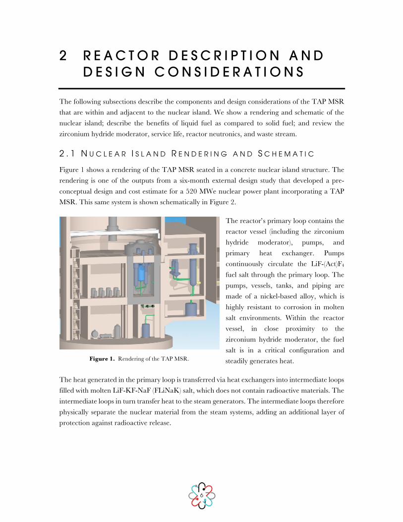
Figure 1 shows a rendering of the TAP MSR seated in a concrete nuclear island structure. The rendering is one of the outputs from a six-month external design study that developed a pre-conceptual design and cost estimate for a 520 MWe nuclear power plant incorporating a TAP MSR. This same system is shown schematically in Figure 2.
The reactor’s primary loop contains the reactor vessel (including the zirconium hydride moderator), pumps, and primary heat exchanger. Pumps continuously circulate the LiF-(Act)F4 fuel salt through the primary loop. The pumps, vessels, tanks, and piping are made of a nickel-based alloy, which is highly resistant to corrosion in molten salt environments. Within the reactor vessel, in close proximity to the zirconium hydride moderator, the fuel salt is in a critical configuration and steadily generates heat.
The heat generated in the primary loop is transferred via heat exchangers into intermediate loops filled with molten LiF-KF-NaF (FLiNaK) salt, which does not contain radioactive materials. The intermediate loops in turn transfer heat to the steam generators. The intermediate loops therefore physically separate the nuclear material from the steam systems, adding an additional layer of protection against radioactive release.
Figure 1. Rendering of the TAP MSR.

7
Figure 2. Simplified reactor schematic, depicting the primary loop, intermediate loop, drain tank, and outlet to the fission gas processing system. Figure legend: A) reactor vessel, B) fuel salt pumps, C) primary heat exchangers, D) freeze valve, E) primary loop drain tank, F) intermediate loop salt pump, G) steam generator, H) intermediate loop drain tank, and I) fuel catch basin.
The steam generators use the heat from the intermediate loop to boil water into steam, which is then fed into a separate building that houses the turbine. The reactor runs at a higher temperature than conventional reactors do: the salt exiting the reactor core is approximately 650°C, whereas the core exit temperature for water in an LWR is only about 330°C (for a pressurized water reactor) or 290°C (for a boiling water reactor). The thermal efficiency when connected to a standard steam cycle is 44%, compared to 34% in a typical LWR. This higher efficiency directly reduces capital costs because it permits the use of smaller turbines, which are a major expense for nuclear power plants. Additionally, supercritical carbon dioxide (S-CO2) looks to be the future of power cycle technology [3], and could allow the plant to achieve even higher efficiencies while minimizing both component wear and cooling requirements.
The nuclear island also contains fission product removal systems. The majority of fission products are continuously removed via either an off-gas system or a chemical processing system. As these byproducts are gradually removed, a small amount of fuel is regularly added to the primary loop. This process maintains a constant fuel mass and allows the reactor to remain critical for decades. Through continuous fueling and filtering of key fission products we are able to process the initial fuel load in the reactor for long periods of time, on the order of decades, as compared to a typical four-year lifetime in an LWR.
2 . 2 L I Q U I D F U E L V S . S O L I D F U E L
Nearly all currently operating commercial reactors use solid uranium oxide fuel. The uranium oxide, in the form of solid pellets, is surrounded by a metal cladding that helps maintains the fuel’s position within the reactor and provides a barrier to the release of fission products into the

8
surrounding coolant. In contrast, Transatomic Power’s reactor uses liquid fuel instead of solid fuel pellets, with uranium dissolved in a molten fluoride salt. This salt acts as both fuel and coolant, as it both provides fissile material to the core and carries heat out of the core to an intermediate loop.
2 . 2 . 1 H I G H E R O U T L E T T E M P E R A T U R E S
Liquid fuel offers significant advantages during normal operation, primarily by permitting better heat transfer. This in turn allows for higher reactor outlet temperatures, which lead to a higher overall thermal efficiency for the plant.
In a commercial LWR, water is used as a working fluid to transfer heat from the hot outer surface of the fuel cladding (typically at about 330°C) to the plant’s power conversion loop. A higher cladding temperature allows for a higher water temperature, which allows for a more efficient power production cycle. However, the uranium oxide fuel material is a poor heat conductor, and therefore, as shown in Figure 3, the centerline temperature of the fuel pin must be very high (up to 2000°C in a pressurized water reactor (PWR)) to generate an acceptably high temperature on the outer wall of the cladding. In most LWRs, it is not possible to increase the outer cladding temperature significantly beyond 330°C, because that would result in an unacceptably high fuel centerline temperature. A liquid-fueled reactor does not encounter these issues, as its fuel is constantly circulated and cooled via the intermediate loop. The fuel salt is a good heat conductor, and therefore can have both a lower peak temperature and a higher outlet temperature than a solid fueled reactor.
Figure 3. Temperature profile of an LWR’s solid fuel pin, from center to edge, compared to the temperature profile of a TAP MSR’s fuel-salt.
0
500
1000
1500
2000
2500
0 1 2 3 4 5
Tem
pe
ratu
re (ᵒC
)
Radius (mm)
PWR TAP
Higher outlet temperature for efficiency
Lower peak temperature for safety

9
2 . 2 . 2 E A S I E R T O R E M O V E D E C A Y H E A T
Solid fueled reactors must bring coolant to their fuel in an accident scenario. If either coolant or cooling power is lost, decay heat production can quickly raise the reactor core temperature to levels high enough to severely damage its structure.
LWRs were originally invented for use in submarines, which can use the ocean as an effectively infinite heat sink. On land, commercial power plants must reserve enough water in tanks and maintain enough electrical power (either from the grid or from diesel generators) to drive pumps to sustain emergency cooling for a day or more, until help can arrive with more water and power. The more advanced plants now being built in the U.S. are designed to extend the self-sufficiency period to 72 hours; however, local aid may not be available by then. As events at Fukushima Daiichi demonstrated, a breakdown in transportation infrastructure to deliver emergency assistance can greatly exacerbate a reactor accident.
Unlike solid fueled reactors, liquid fueled reactors can drain fuel directly out of the core. This drainage can happen quickly, without pumping, through the use of passive safety valves and the force of gravity. One such passively safe drainage mechanism, the freeze valve, was tested repeatedly with success during the ORNL MSRE [1]. A freeze valve consists of a drain in the reactor leading to a pipe that is plugged by a solid core of salt. The salt remains solid via electric cooling. If the reactor loses external electric power, the cooling stops, the plug melts, and fluoride salt drains out of the reactor core into an auxiliary containment vessel. Fission ceases both because the fuel is separated from the moderator and because of the relatively high surface area geometry of the auxiliary tank. The high surface area to volume ratio in the auxiliary tank allows molten salt reactors to effectively change their fuel geometry to speed cooling after an accident.
The decay heat of the auxiliary tank is low enough to be removed by natural convection via a cooling stack, thereby eliminating the need for electrically-pumped coolant. As provided in our design study with Burns & Roe, a cooling loop in the auxiliary tank is connected to a stack and allows for 25 MW of passive cooling to the fuel, adequate to air-cool the entire fuel salt inventory from liquid to solid state within 1.5 to 3 hours without outside power or coolant.
Figure 4 shows the temperature of the fuel salt inventory in the auxiliary tank as a function of time with 25 MW of cooling. The upper and lower bounds for the cooling curve are shown as dashed lines. Thermal data for the salt is based on molecular dynamics simulations [4] and extrapolated experimental data [5].
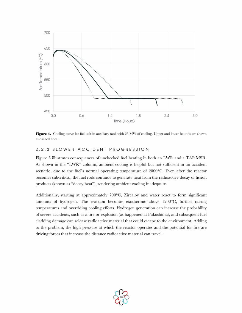
10
Figure 4. Cooling curve for fuel salt in auxiliary tank with 25 MW of cooling. Upper and lower bounds are shown as dashed lines.
2 . 2 . 3 S L O W E R A C C I D E N T P R O G R E S S I O N
Figure 5 illustrates consequences of unchecked fuel heating in both an LWR and a TAP MSR. As shown in the “LWR” column, ambient cooling is helpful but not sufficient in an accident scenario, due to the fuel’s normal operating temperature of 2000°C. Even after the reactor becomes subcritical, the fuel rods continue to generate heat from the radioactive decay of fission products (known as “decay heat”), rendering ambient cooling inadeqaute.
Additionally, starting at approximately 700°C, Zircaloy and water react to form significant amounts of hydrogen. The reaction becomes exothermic above 1200°C, further raising temperatures and overriding cooling efforts. Hydrogen generation can increase the probability of severe accidents, such as a fire or explosion (as happened at Fukushima), and subsequent fuel cladding damage can release radioactive material that could escape to the environment. Adding to the problem, the high pressure at which the reactor operates and the potential for fire are driving forces that increase the distance radioactive material can travel.
450
500
550
600
650
700
0.0 0.6 1.2 1.8 2.4 3.0
Salt
Tem
pe
ratu
re (ᵒC
)
Time (Hours)

11
Figure 5. Key temperatures for an LWR and a TAP MSR.
After an emergency situation, such as a loss of power to the reactor plant site, these overheating accident scenarios can develop within minutes. An LWR core, filled with solid fuel pellets that are poor heat conductors, can require external cooling for years before decay heat drops to a negligible level. This mismatched timing (minutes to overheat versus years to cool off) makes nuclear safety for LWRs enormously challenging, and leaves these reactors particularly vulnerable to extremely rare disasters that were not incorporated into the reactor’s safety profile, known as “beyond design basis” accidents.
Molten salt reactors inherently avoid these issues through material selection. As shown in the “TAP” column in Figure 5, a molten salt reactor operates between 500 and 700°C, far below the salt’s boiling point of approximately 1200°C. The thermal mass of the fuel is now an asset instead of a liability, as it serves to resist any sudden heat increase. If the reactor temperature were to climb, temperatures greater than 700°C passively melt a freeze valve (discussed in the “Better Inherent Safety” section of this paper), which drains fuel from the reactor and allows it to flow into a subcritical configuration with a high surface area. The subcritical molten salt still generates decay heat, but the high surface area allows it to readily dissipate heat via passive cooling mechanisms.
At the other end of the temperature spectrum, the salt safely freezes in place if temperatures drop below 500°C. Unlike water, the salt becomes denser after it freezes, so this condition does not
0
600
1200
1800
2400
3000
Tem
pe
ratu
re (ᵒ
C)
Acident Scenario Operating Condition Inherent Safety Features
LWR TAP
Salt Solidifes, <500 ᵒC
Freeze Valve Melts, >700 ᵒC
Salt Boils, >1200 ᵒC
Vessel Yield Point, >1300 ᵒC
Core Coolant OutletTemperature, 315 ᵒC
Hydrogen Generation, Zircaoly Water Reaction, >700 ᵒC
Cladding Damage, Radiation Release, Exothermic Hydrogen
Generation, >1200 ᵒC
Fuel Temperature, <2000 ᵒC
Fuel Melts >2800 ᵒC

12
increase system pressure. As the TAP MSR operates near atmospheric pressure and has few conditions that could create strong driving forces, the solid salt and its fission products remain safely contained.
In addition to the inherent safety benefits of liquid fuel, the TAP plant design has additional safety features and containment strategies for defense in depth. These safety features and strategies are discussed further in Section 3.
2 . 3 S A L T F O R M U L A T I O N
The vast majority of past work on molten salt reactors has used a lithium-beryllium-fluoride salt (FLiBe). Transatomic Power’s reactor instead uses a LiF-based fuel salt that dissolves a fuel consisting of 5%-enriched uranium tetrafluoride. One drawback of this salt is that its melting point is higher than that of FLiBe, and thus the primary loop piping must be carefully designed to avoid cold spots that could restrict flow and induce freezing. We chose to accept this engineering challenge for two reasons:
1. LiF-(Act)F4 is capable of containing a higher concentration of uranium than FLiBe salt. Therefore, each unit volume of our fuel salt has a higher amount of uranium than would be possible using FLiBe. This salt composition thus helps us operate using LEU.
2. FLiBe contains beryllium, which can lead to chronic berylliosis in a significant portion of the population. Forgoing beryllium use thus imparts an occupational health benefit as well.
An additional issue, present in all nuclear reactors, is tritium generation. Tritium is a radioactive isotope of hydrogen and can bind with water; although it has a fairly short half-life, above certain levels it could be biologically hazardous. Tritium held within the primary loop, intermediate loop, and containment cell is acceptable, because it is not entering the environment and can readily be scrubbed from these systems. The expected annual tritium generation of a TAP MSR would be above that of an equivalently sized LWR but less than that of an equivalently sized heavy water reactor (HWR), such as a CANDU: 50 grams per year for a TAP MSR versus 50 – 100 grams per year for an HWR, depending on design [6]. Therefore, the TAP MSR can contain tritium emissions and be consistent with other commercial reactors’ tritium handling. Minimizing tritium risk is also an ongoing area of TAP technical research.
Tritium production may be minimized by enriching the salt in lithium-7. Lithium-7 has a much lower neutron absorption cross section than does lithium-6, so it both absorbs fewer neutrons and generates less tritium per unit mass than lithium-6 [7]. The majority of the generated tritium is then removed by the primary loop off-gas system and stored in waste containers, as described in Section 2.6.3.

13
2 . 4 Z I R C O N I U M H Y D R I D E M O D E R A T O R
A defining difference between Transatomic Power’s reactor and other molten salt reactors is its zirconium hydride moderator, which we use instead of a conventional graphite moderator. Using this moderator is an important advancement. Early molten salt reactors, such as the ORNL Molten Salt Reactor Experiment (MSRE), used a graphite moderator that would shrink and swell over time under irradiation [1]. These dimensional changes not only reduced mechanical integrity, they also complicated reactor operation, since the degree of change and quality of moderation varied over time and spatially within the core. This variability made it necessary to replace the graphite every four years.
In contrast, zirconium hydride moderator rods experience substantially less volumetric change than graphite does under neutron irradiation [8]. Additionally, zirconium possesses a low neutron absorption cross section and high resistance to radiation damage, while hydrogen is a highly effective moderator. The reactor core contains moveable zirconium hydride rods,1 as shown in Figure 7, which are surrounded by cladding to protect the moderator from the corrosive molten salt environment. The moderator region is surrounded by a blanket of unmoderated fuel salt, which serves as both a reflector and a fertile nuclei conversion zone.
Figure 7. TAP MSR core cross-section, showing moderator rod bundles.
The available experimental data suggest that the service lifetime of the moderator rods will be at least four years; additional in situ testing is needed to determine the full extent of the service
1 See Section 2.6 for more information.

14
lifetime. Ultimately, it may not be necessary to replace the zirconium hydride moderator assemblies over the lifetime of the plant; however, the design currently provides for maintenance access to the rods for evaluation and replacement.
In the design for the ORNL Molten Salt Breeder Reactor (MSBR), 80–90% of the core volume was occupied by the graphite, leaving only 10–20% of the core for fuel salt. It was therefore necessary to enrich the uranium in the fuel salt to 33% U-235 [1]. This high enrichment level was acceptable for a U.S. national lab experiment; however, it exceeds the LEU limit of 20% U-235 and is well above the 5% U-235 enrichment level typical of commercial power reactors. Higher enrichments are discouraged due to their proliferation concerns.
By comparison, zirconium hydride’s high hydrogen density, coupled with its favorable neutron scattering properties, allows it to achieve the same degree of thermalization as graphite in a much smaller volume. The zirconium hydride moderator therefore allows us to significantly shrink the reactor core volume, thereby reducing the size and cost of the reactor vessel and the volume of fuel salt. In Transatomic Power’s reactor, the maximum fraction of the core volume occupied by moderator is roughly 50%, which allows for more than five times more fuel salt in the same size core, allowing better performance, reduced enrichment, and lower cost.
One of the factors we examined in selecting a zirconium hydride moderator is the stability of hydrogen in zirconium hydride at high temperature and under irradiation. The available data are extensive, and show that hydrogen migration (and thus phase-change risk) is minimal at the temperatures and neutron fluxes present in the TAP MSR. The Soviet TOPAZ reactors, which generated thermionic power for satellites, demonstrated the effectiveness of their zirconium hydride moderator in experimental tests on the ground and in orbit [9]. According to experiments performed in conjunction with the TRIGA [10] and SNAP [11] reactors, both of which used uranium zirconium hydride fuel, zirconium hydride remains stable in a reactor core at temperatures at least up to 750°C. According to Simnad, “... [Z]irconium hydride can be used at temperatures as high as 750°C under steady-state and 1200°C under short transient pulse operation [10].”
Modest hydrogen redistribution may occur within the moderator, because there exists a temperature gradient within the moderator rod. The moderator is internally heated through gamma heating and neutron scattering; the centerline temperature of the moderator rod will therefore be approximately 40°C higher than the bulk salt. Some experimental data are available for temperature gradient-driven hydrogen diffusion in zirconium hydride.
Huangs et al. tested a temperature gradient of 140°C in a ZrH1.6 rod, with a centerline temperature of 645°C and a surface temperature of 505°C. Their steady-state result showed ZrH1.7 on the surface and ZrH1.5 at the centerline [12]. Our research indicates that this hydrogen

15
concentration gradient, or even a gradient several times larger than this, would not be detrimental to reactor function.
Additional work by Ponomarev-Stepnoi et al., in which zirconium hydride blocks were thermally cycled up to 650°C, found “statistically negligible” hydrogen emission after 4.1 years, and a maximum of 2% emission after 10 years of thermal cycling [13]. Further experimental data describing the stability of zirconium hydride at high temperature and in a radiation environment are listed in the Moderator Stability addendum to this paper.
We conclude that significant hydrogen outgassing will not occur in this reactor under normal operating conditions. However, if significant hydrogen outgassing occurs, the zirconium hydride moderator will become less effective (with less hydrogen present), and thereby reduces reactivity2 in the core. Zirconium on its own essentially does not moderate neutrons. Free hydrogen diffuses through the cladding and into the salt, where it bubbles out and is removed continuously by the outgas system. This feature bears some similarity to the inherent safety of uranium-hydrogen fuel used in TRIGA reactors and represents an added safety benefit over previous molten salt reactors. Even in an extreme accident scenario, including off-gas removal failure, the system is designed so that the hydrogen concentration is never high enough to allow for a hydrogen explosion.
2 . 5 M A T E R I A L S T A B I L I T Y
The reactor’s primary loop piping, reactor vessel, valves, pumps, and heat exchangers will be made from a nickel-based alloy that is both corrosion-tolerant in molten salt environments and approved for high temperature nuclear applications by the American Society of Mechanical Engineers (ASME) Boiler and Pressure Vessel Code Section III. While other materials such as Hastelloy-N were developed specifically for molten fluoride systems [14], they do not fall under current ASME Code Cases, and thus their use would likely add many years to technology development timelines. Our recent material research suggests that a previously certified nickel-based alloy with favorable irradiation and corrosion properties could be used instead.
A major focus of our experimental work is the mechanical integrity of the primary loop piping materials. First, thermal striping, when temperature fluctuations occur at the interface of two fluid jets at different temperatures, may lead to mechanical fatigue and subsequent crack initiation. Fluid dynamics simulations of the reactor vessel can partially predict these effects, and they can be tested at smaller scales as well.
2 Reactivity is a measure of the change in neutron population from one generation of neutrons to the next. If reactivity is positive, more neutrons are being produced each generation than are being lost, and the reactor’s fission rate will increase. Conversely, if reactivity is negative, the neutron population will fall and the fission rate will decrease. A reactivity of 0 indicates no change in the neutron population from one life cycle to the next, with the nuclear chain reaction self-sustaining; the reactor is then considered “critical.”

16
Second, welding and joining issues in the primary loop are issues that all high temperature piping systems face. The piping joints are the weakest links in the primary loop, and it is important to confirm that they retain their mechanical and material integrity throughout reactor operation. Furthermore, it is vital to ensure that welding materials are compatible with the molten salt and do not exacerbate corrosion effects.
One benefit inherent to most molten salt reactor designs is that the piping and vessel walls are thinner than those of an LWR (because of the lower-pressure piping in a molten salt reactor), which reduces the possibility of inadvertently stressing the metal while welding. Welding and joining issues can be examined readily in small-scale test loops.
In the future, the reactor may be adapted to use high-temperature ceramics, such as SiC-SiC fiber composites, in place of nickel-based alloy components. Moving from metals to ceramics will allow us to further increase the reactor’s operating temperature, thereby increasing the system’s thermal efficiency and enabling a broader range of process heat applications.
2 . 6 N E U T R O N I C S , F U E L C A P A C I T Y , A N D W A S T E S T R E A M
2 . 6 . 1 R E A C T O R N E U T R O N I C S
Molten salt reactors possess remarkable fuel versatility, as they can be powered by a range of different fissionable materials. Although initially we have chosen to focus on the commercial 5%-enriched uranium cycle, allowing us to utilize the current supply chain, the design is flexible enough to accommodate higher levels of enrichment, which could further increase performance and reduce waste production.
Driven by the assumption of a system in which a solid fuel must be regularly replaced because of the build-up of fission product gases and radiation damage, conventional wisdom holds that only a fast reactor can effectively tap a significant portion of the energy contained in nuclear fuel. Under this assumption, only fast reactors have neutron economies that can destroy enough actinides in a short enough period of time before fission product buildup and cladding damage necessitate refueling. Fast reactors accomplish this actinide burning by using neutrons at high kinetic energies, where the fission-to-capture ratio is high, with the drawback that the reactor core is exposed to extremely challenging radiation damage.
The TAP MSR addresses this challenge by revisiting and inverting fundamental assumptions about nuclear reactor technology. To begin with, a reactor’s ability to achieve criticality is a function of two parameters: the core’s geometry and its material composition. In solid-fueled reactors, the core’s geometry is fixed, since the fuel and the moderator surrounding it do not change their relative positions. Additionally, in LWRs, reactivity inherently decreases over time as the fuel depletes and fission product poisons accumulate within the fuel rods. Therefore, an LWR core must initially have significant excess reactivity to ensure that the reactor remains
17
critical for the entirety of its fuel cycle. Sufficient excess reactivity is generated by increasing the quantity of fissile material in the core at the beginning of the reactor’s life, and requires control rods that absorb surplus neutrons in order to keep the reactor stable. This use of control rods leads to an inefficient use of the neutron population that contributes to an LWR’s low fuel utilization.
In a TAP MSR, multiple features eliminate the need for excess reactivity. First, online refueling and fission product removal control reactivity. Fuel can be added to the core continuously to counteract fuel depletion, and fission products are extracted (either continuously or in batches) to minimize the accumulation of fission product poisons. These measures by themselves significantly increase the burnup TAP MSRs can achieve. Furthermore, there is another feature of the TAP MSR that ensures the most efficient use of neutrons and allows the reactor to operate with no excess reactivity: moveable moderator rods.
In all thermal reactor designs, the volumetric fraction of fuel in the core is an essential variable for reactivity control. The TAP MSR’s design allows operators to modify this parameter, quantified by the percentage of the core occupied by fuel salt, or the core’s Salt Volume Fraction (SVF). With moveable moderator rods, operators can alter the core’s SVF over time, effectively modifying the core’s geometry. This obviates the need for excess reactivity, since the core’s moderator rods can be inserted over time to maintain criticality, decreasing the SVF and ensuring the most efficient possible use of neutrons.3
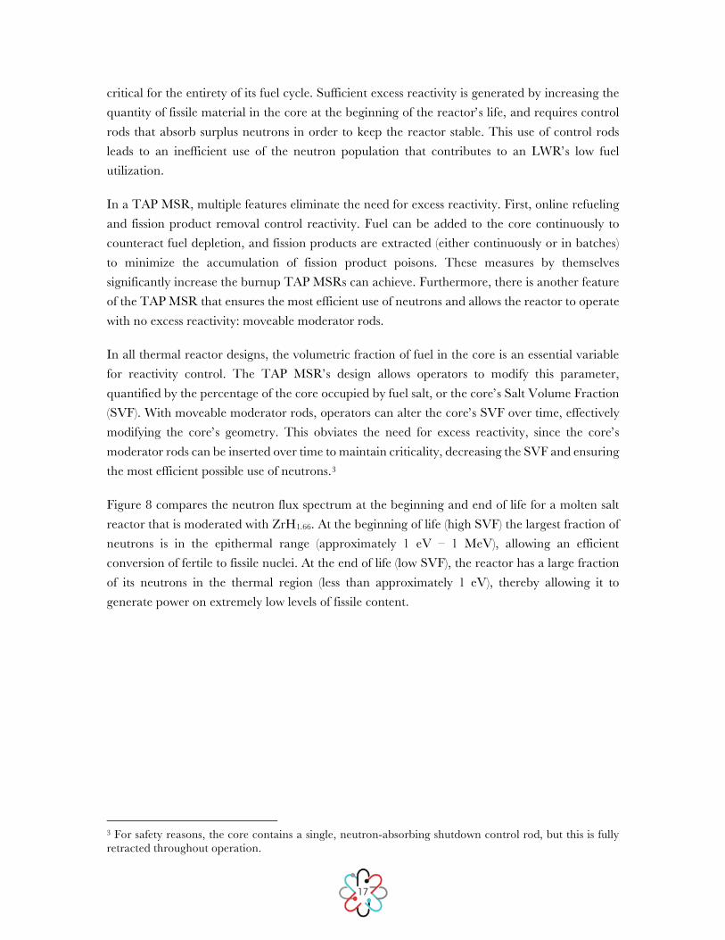
Figure 8 compares the neutron flux spectrum at the beginning and end of life for a molten salt reactor that is moderated with ZrH1.66. At the beginning of life (high SVF) the largest fraction of neutrons is in the epithermal range (approximately 1 eV – 1 MeV), allowing an efficient conversion of fertile to fissile nuclei. At the end of life (low SVF), the reactor has a large fraction of its neutrons in the thermal region (less than approximately 1 eV), thereby allowing it to generate power on extremely low levels of fissile content.
3 For safety reasons, the core contains a single, neutron-absorbing shutdown control rod, but this is fully retracted throughout operation.

18
Figure 8. Neutron spectrum in a zirconium hydride moderated TAP MSR at the beginning and end of life.
The combination of the TAP MSR’s particularly efficient neutron economy and molten salt reactors’ general ability to continuously remove fission products allows the reactor to achieve a high burnup using 5%-enriched uranium from the existing fuel supply chain.
2 . 6 . 2 W A S T E S T R E A M
The TAP MSR produces significantly less waste than conventional LWRs. A 520 MWe LWR would generate annually approximately 10 metric tons of spent nuclear fuel (SNF), which contains materials with half-lives on the order of hundreds of thousands of years. In contrast, the annual waste stream from a similarly-sized TAP MSR is reduced from 10 to 0.5 metric tons. Even when considering the long-lived actinide waste that exists at the end of life, there is still more than a 50% waste reduction. Furthermore, the vast majority of our operational waste stream (the lanthanides, krypton, xenon, tritiated water vapor, noble metals, and semi-noble metals) has a relatively short half-life, on the order of a few hundred years or less. We believe humankind can tractably store waste materials on these timescales, compared to the hundreds of thousands of years required for long-lived actinide waste.
The TAP MSR uses three distinct fission product removal methods:
Off-Gas System. An off-gas system removes fission products such as krypton and xenon, which are then compressed and stored temporarily until they have decayed to background levels. Trace amounts of tritiated water vapor are also removed and bottled via the same process. In addition, the off-gas system also directly removes a small percentage of the noble metal fission products.
0.00E+00
5.00E-03
1.00E-02
1.50E-02
2.00E-02
2.50E-02
1.00E-09 1.00E-07 1.00E-05 1.00E-03 1.00E-01 1.00E+01
Flux
Fra
ctio
n (
1/d
U)
Energy (MeV)
BOL EOL

19
Metal Plate-Out/Filtration. Noble and semi-noble metal solid fission products, as well as other species that form colloids in the salt, are removed from the salt as they plate out onto a nickel mesh filter located in a side stream in the primary loop.
Liquid Metal Extraction. Lanthanides and other non-noble metals remain primarily dissolved in the fuel salt. Though they generally have a lower capture cross-section and thus absorb fewer neutrons than xenon, their removal is essential to ensuring nominal operation. This is accomplished via a liquid-metal/molten salt extraction process being developed by others in the USA and France that converts the dissolved lanthanides into a well-understood oxide waste form, similar to that of LWR SNF. This oxide waste comes out of the processing facility in ceramic granules and can be sintered into blocks or an alternative form convenient for storage.
Table 1 illustrates the breakdown of removal methods and approximate fission product quantities produced per year by one 520 MWe plant.
Table 1. Fission product removal methods and approximate average production rate. Adapted in part from [15].
Fission Product Removal Process Production Rate Waste Form
3H, Kr, Xe, Helium Sparging 100 kg/year Compressed
Gas
Zn, Ga, Ge, As, Se, Nb, Mo, Tc, Ru, Rh, Pd, Ag, Cd, In, Sn, Sb, Te, I
Filtration and Helium Sparging
200 kg/year Metallic
Cr, Fe, Ni, Rb, Sr, Y, Zr, Cs, Ba, La, Ce, Pr, Nd, Pm, Sm, Eu, Gd, Tb, Dy, Ho, Er
Molten Salt/Liquid Metal Extraction
200 kg/year Solid Oxides
Of the lanthanide mass removed by liquid metal extraction, we estimate that approximately 10% will be actinide contaminants with a longer half-life similar to that of SNF. It may be most practical to leave such a small quantity embedded within the lanthanide mass, as it would be well distributed and would not materially extend the time for the overall waste form to reach background levels. However, if desired, the actinides can be further separated offsite with additional post-processing techniques.
In summary, with current commercially-available fuel supplies, the TAP MSR generates less than 50% of the waste of a large LWR, greatly reducing the requirement for eventual long-term repositories.

20
3 B E T T E R I N H E R E N T S A F E T Y
Molten salt reactors provide significant benefits for public safety. The main concern in a nuclear emergency is to prevent the release of fission products to the environment. To prevent this occurrence, the TAP MSR’s materials and design greatly mitigate the risk of dangerous reactor temperature and pressure surges, minimize driving forces that can widen a release, and provide redundant containment barriers for defense in depth.4
3 . 1 S E L F - S T A B I L I Z I N G C O R E
Like LWRs, MSRs have strongly negative void and temperature coefficients.5 These negative coefficients greatly aid reactor control and act as a strong buffer against temperature excursions. As the core temperature increases, the salt expands. This expansion reduces the density of fissile material in the core, thereby slowing the fission rate without operator intervention. Additionally, U-238’s neutron capture cross section also increases with temperature due to the Doppler effect.
As with an LWR, operators take advantage of these properties in order to control the TAP MSR’s power level via turbine steam flow adjustments. Reducing steam flow extracts less heat from the salt, thereby increasing its temperature, which in turn decreases the thermal power generated in the core. Once the reactor reaches the desired power level where heat produced is equal to the turbine heat draw, the system re-stabilizes. These dynamics provide negative feedback loops and provide the system with inherent stability.
A final benefit of the TAP MSR design is its lack of excess reactivity, discussed in Section 2.6. Minimizing excess reactivity reduces the possibility of very large power transients, and, therefore, a continuous withdrawal of control rods or insertion of moderator rods will have a substantially muted effect on reactor power.
3 . 2 S M A L L E R I N V E N T O R Y O F R A D I O N U C L I D E S
As shown in Table 2, a typical 1000 MWe LWR core has an inventory of 2 to 7 tons of non-uranic radionuclides. These core inventories are used to calculate the source terms for
4 “Defense in depth” refers to “multiple independent and redundant layers of defense to compensate for potential human and mechanical failures so that no single layer, no matter how robust, is exclusively relied upon [33].” Additionally, per the NRC’s policy guidance, advanced reactor designs “will provide enhanced margins of safety and/or use simplified, inherent, passive, or other innovative means to accomplish their safety and security functions [34],” goals that the TAP MSR accomplishes. 5 These coefficients are the proportional changes in reactivity for a given change in a reactor parameter. For example, a negative temperature coefficient is such that as temperature increases, negative reactivity is inserted into the reactor.

21
radionuclide release in various accident scenarios. By convention, these core inventory numbers do not include uranium.
For an equivalent power output, a TAP MSR requires less source material than an LWR does, because it has a higher thermal efficiency. Furthermore, noble gases, noble metals, and lanthanides are removed continuously from the system, as shown previously in Table 1. This reduction shrinks the maximum size of a potential release.
Table 2. Radionuclide inventories (normalized to 100 MWe, net generation) in the primary loop for boiling water reactor (BWR), PWR, and TAP MSR accident analyses. BWR and PWR numbers, chemical groups, and elements in the groups are adapted from [16]. Following [16], Low Burnup indicates an average burnup of 28 GWd per MTHM and High Burnup indicates an average burnup of 59 GWd per MTHM.
Chemical Group Elements BWR PWR
TAP Reactor* Low Burnup
High Burnup
Low Burnup
High Burnup
Noble Gases Kr, Xe 32 77 26 45 <0.1
Halogens Br, I 1 3 1 2 <0.1
Alkali Metals Rb, Cs 18 44 14 25 1
Tellurium Group Se, Sb, Te 3 7 2 4 <0.1
Alkaline Earths Sr, Ba 14 33 11 19 3
Noble Metals Co, Mo, Tc, Ru, Rh, Pd 44 112 18 32 <0.1
Lanthanides** Y, Nb, La, Pr, Nd, Pm, Sm, Eu, Am, Cm 43 109 34 61 11
Cerium Group Zr, Ce, Np, Pu 106 201 85 126 102
Scaled Total (kg per 100 MWe) 261 586 191 314 117
* Values in the primary loop at the end of life, assuming fission product removal as described in Section 2.6.3. ** By convention in NUREG-1246, Cm and Am are placed in the lanthanide group.
3 . 3 R E D U C E D D R I V I N G F O R C E
As described in our comparison of solid and liquid fuels, LWRs can experience enormous driving forces during accident scenarios. These forces can originate from a hydrogen explosion, a steam explosion, or, in some reactors, a high system pressure of 150 atmospheres.
Driving forces are greatly reduced in a TAP MSR because the reactor operates at near-atmospheric pressures and because there is minimal chance of a vapor explosion due to fuel salt’s chemical properties. Additionally, we utilize existing rupture disk technology to protect against upstream pressure transients; these passively reduce system pressure without any external action.

22
3 . 4 I N H E R E N T S A F E T Y
By definition, a walk-away safe nuclear reactor is one that does not require operator action or electrical power to shut down safely in an emergency. Further, the reactor must be able to safely cool during an extended station blackout without any outside emergency measures. An inherently safe reactor will be able to achieve these goals even in the face of “beyond-design-basis” events, such as the earthquake-tsunami combination that crippled the Fukushima Daiichi power plant.
The TAP MSR represents a major advance over LWRs because it is walk-away safe (primarily because of its freeze valve) and can passively cool its drained core via cooling stacks connected to its auxiliary tank. If the freeze valve fails, the shutdown rod may be inserted either passively via an electromagnetic failsafe or by operator action, thereby making the reactor subcritical. If the shutdown rod or other active measures cannot be used, the hot fuel salt will simply remain in the reactor vessel. Heat will cause the salt to expand, thereby reducing reactivity. If the freeze valve fails and the salt continues to increase in temperature, the zirconium hydride moderator rods will decompose, with a minor release of hydrogen gas that is not large enough to pose an explosion threat. The lack of sufficient neutron moderation brings the reactor to a sub-critical state.
If the salt temperature increases sufficiently to induce material failure in the vessel, then the salt will flow via gravity into a catch basin, shown in Figure 2, located immediately below the vessel. The catch basin in turn drains via gravity into the auxiliary tank. The reactor and its catch basin are sealed within a concrete chamber only accessible by hatch. Thus, even in this worst-case accident scenario, the system is both confined and non-flammable, while shutting down passively. If fuel salt through some further circumstance escapes the primary containment surrounding the primary loop, it will still be inside the concrete secondary containment structure, which is located at least partially below grade. An intermediate loop creates a buffer zone between the radioactive materials in the reactor and the non-radioactive water in the steam turbine. The steam is at a higher pressure than the intermediate loop and the intermediate loop is at a higher pressure than the primary loop; any leaks in heat exchangers will cause a flow toward the core rather than out of the core. In the event that any radionuclides migrate into the intermediate loop, both the loop and the steam generator it feeds are confined within the concrete secondary containment structure. If the fuel salt, despite all existing safety mechanisms in the system, escapes the containment structure, it will return to solid form once it cools below approximately 500°C, which will rapidly occur in most ambient conditions.
Table 3 summarizes how fundamental material choices affect key safety aspects for LWRs and TAP MSRs. TAP MSRs have greater inherent safety, which is particularly important for events that have historically been considered to be beyond-design-basis events.

23
Table 3. A comparison of key safety features for a typical 1 GWe LWR and TAP’s 520 MWe MSR
LWR TAP MSR
Negative Reactivity Coefficient Yes Yes Primary Loop Radionuclide Inventory (kg per 100 MWe) 200 - 600 ~250
System Pressure (atm) 150 1
Coolant Boiling Risk Yes No
Hydrogen Explosion Risk Yes No
In conclusion, an explosion or steam rupture in an LWR plant might have wide area consequences, so safety must be assured probabilistically through the use of multiple independent or redundant systems, unavoidably adding cost and complexity. TAP MSRs draw on these redundant techniques in places, but we ultimately provide a more resilient safety foundation: molten salt is inherently less capable of a wide-area public disaster.

24
4 R E A C T O R C O S T
There is a range of commercial power plants that can be envisioned using Transatomic Power’s technology. We worked with Burns & Roe, an experienced nuclear engineering, procurement, and construction firm, on a system-wide pre-conceptual plant for a 550 MWe (gross generation) TAP MSR, with a net output of 520 MWe.
Such a plant could serve as a replacement for aging coal plants, in contrast to today’s most modern LWRs (typically large units aimed at least 1000 MWe), and small modular reactors (SMRs; defined as less than 300 MWe). The overnight cost for an nth-of-a-kind 520 MWe size, including on-line fission product removal and storage, is estimated at $2.0 billion with a three-year construction schedule.
The TAP MSR can realistically achieve these overnight costs because the outlet temperature of 650°C allows for higher thermal efficiency than current LWR temperatures of 290-330°C, enabling significant savings in the turbine and balance of plant costs. Additional savings occur because (1) the reactor and heat transfer equipment operate near atmospheric pressures, reducing complexity and expense for both equipment and structures; and (2) the reactor’s inherent safety characteristics reduce the requirement for multiple redundant safety systems.
There are several cost disadvantages for the TAP MSR that were anticipated in this analysis, as well. We must keep our piping warm to prevent salt freeze-outs, and we need to contend with tritium generation. We also use an intermediate loop filled with non-radioactive salt to separate the steam cycle from the fuel-salt and require structural space for fission product removal. Nevertheless, the analysis shows the savings described above greatly outweigh these cost additions.
Our $2 billion overnight cost estimate at nth-of-a-kind scale includes lithium-7 (a key salt component) and custom fission product processing equipment. Our reactor’s strong neutronics benefit us in permitting the use of slightly less pure lithium-7 and somewhat less frequent fission processing than previous MSR designs [17]. Our salt also does not incur the costs associated with handling beryllium, which may make it less expensive than LiF-BeF2 salt. Currently, no robust supply chain exists for these materials; we therefore have used our best internal estimates as to procurement cost, taking into account the current price of lithium-7. The allocation for these expenses is less than 10% of the overall budget.
The $2 billion price point can greatly expand the demand for nuclear energy, because it has a lower entry cost than do large-sized nuclear power plants. The Vogtle 3 and 4 plants, each 1100 MWe and built in parallel, have a combined project cost of over $19 billion for approximately four times higher output [18]. Similarly, the Flamanville EPR is estimated to cost $11.7 billion

25
for 1630 MWe, or just over three times higher output [19]. Even if the cost per watt were the same, a lower price for a smaller unit will still expand the number of utilities that can afford to buy nuclear reactors, better match slow changes in demand, allow greater site feasibility, and reach profitability faster. The speed of construction and faster payback also reduce financing costs.

26
5 A N T I - P R O L I F E R A T I O N A N A L Y S I S
The TAP MSR represents major victories for non-proliferation, because (1) it eliminates the need for new enrichment facilities, (2) it eliminates the need for actinide separation, and (3) it reduces SNF production.
Countries that rely on traditional nuclear power plants may understandably argue that their nuclear power program requires developing a domestic fuel supply, including access to both an enrichment facility, either domestic or foreign, and a reprocessing facility to handle waste. However, enrichment facilities pose a proliferation risk because they contain equipment to enrich uranium, and reprocessing facilities pose a proliferation risk because they have the potential to separate plutonium.
The TAP MSR, however, minimizes the need for these facilities. By producing electricity more efficiently per ton of uranium, TAP MSRs would enable already existing enrichment capacity to meet the fuel needs for a vastly larger nuclear power industry. A lifetime supply of 5% enriched fuel could be delivered to the plant at time of construction with little proliferation risk, thus assuring the resource independence the host country desires.
Today, proliferation risks require that all SNF be guarded in perpetuity. Even though SNF has fairly poor isotopic composition for making a nuclear weapon, it does contain enough plutonium for one atomic bomb if the proper isotopes could be completely extracted [23]. The world has accumulated over 300,000 tons of commercial SNF, and the amount is growing by 10,000 tons per year [24], accelerating as the world continues to build more LWRs.
As explained in preceding sections, the TAP MSR reduces SNF production because of its high burnup, and the fuel in our reactor is diluted across a large volume of molten fluoride salt, making theft impractical. Additionally, of the three separate waste streams emerging from the TAP MSR, the off-gas system and noble metal plate out do not contain any material useful for atomic weapons. The third waste stream, made up of lanthanide fission products, will contain minimal actinide contamination. Finally, the TAP MSR has a single-fluid uranium-fueled design. As explained in Section 6, this is far more proliferation resistant than two-fluid thorium-fueled designs, which isolate U-233.

27
6 W H Y N O T T H O R I U M F I R S T ?
The TAP MSR’s primary innovations, a novel combination of moderator and fuel salt, can also be adapted for use with thorium. Transatomic Power believes that the thorium fuel cycle holds theoretical advantages over uranium in the long run because of its generally shorter half-life waste, its minimization of plutonium from the fuel cycle, and its greater natural supply. However, we chose to start with uranium for two primary reasons: (1) the industry already has a commercial fuel cycle developed around uranium, which makes it cheaper to use uranium as fuel; and (2) we already greatly expand the energy potential of existing uranium supplies.
While thorium reactors contain minimal plutonium, they do have a potential proliferation vulnerability because of the protactinium in their fuel salt. Protactinium has a high neutron capture cross section and therefore, in most liquid thorium reactor designs, it must be removed continuously from the reactor. This process yields relatively pure protactinium, which then decays into pure U-233. By design, the pure U-233 is sent back into the reactor where it is burned as its primary fuel. The drawback, however, is that U-233 is a weapons-grade isotope that is much easier to trigger than plutonium.
It is possible to denature the U-233 by mixing it with other uranium isotopes, or to modify the design to further reduce diversion risk, but additional research is required to implement these measures in thorium molten salt reactors. Some may discount the proliferation risk of the thorium fuel cycle because the U-233 in the reactor would be mixed with U-232, rendering it a poor source for proliferation purposes. However, it is the decay products of U-232 that produce high-energy gamma radiation that renders it difficult to handle. Therefore, even with this mixture, it may be possible to chemically extract the decay products before they become gamma emitters, leaving unprotected weapons-grade uranium.

28
7 F U T U R E T A P D E S I G N S
The basic TAP MSR design described in this report will benefit from future innovations in several different ways. Improvements to complementary technology will become commercially available over time. High-temperature ceramics, such as SiC-SiC composites for heat exchangers and other reactor internals, will allow us to increase the reactor’s operating temperature and thermal efficiency. Helium sparging in the primary loop off-gas system may be replaced by more advanced cryogenic removal methods. Furthermore, we will likely be able to incorporate S-CO2 power cycles in the future.
As renewables grow more prevalent and grid supply becomes more variable, we may also adapt the plant for better load-following, as discussed in Section 3.1. Other advanced reactor designs are capable of pseudo load-following, in that a power plant consists of an array of reactors in the range of 50 – 200 MWe, and the individual units are turned off and on depending on power demand. However, multiple stop and restart cycles may damage reactor components.
Furthermore, in solid-fueled reactors, changing the power level too quickly can cause detrimental pellet-cladding interactions, and is hampered by short-lived fission product accumulation. These fission products, particularly xenon, have a severely detrimental effect on conventional reactor performance due to their neutron capture ability, and thus any power changes in solid-fueled, thermal reactors must take place slowly to allow time for xenon to decay.
In contrast, liquid fuel is not tightly constrained by the rate of power change in the reactor. The TAP MSR continuously removes fission products from its liquid fuel, negating the detrimental effect on reactor neutronics. Therefore, although the TAP MSR is meant for baseload operation, its liquid fuel provides for excellent load-following potential.
These technology advances present bright opportunities for nuclear power. Reliable load-following will allow reactors to adapt to rapid changes in electricity demand (particularly as renewable energy penetration accentuates the so-called “duck curve”), and take advantage of the corresponding price fluctuations. Furthermore, increasing plant operating temperature will allow expansion into new markets such as process heat and synthetic fuel production, along with hybrid energy system uses.

29
8 C O N C L U S I O N S
Transatomic Power’s molten salt reactor generates clean, passively safe, and low cost nuclear power from the existing LEU supply chain, something that few, if any, other advanced reactor designs can claim. The most significant differences between this reactor and previous molten salt designs are our zirconium hydride moderator and LiF-(Act)F4 fuel salt, which allow us to achieve a very high actinide burnup in a compact, cost-effective design.
Previous experimental work in conjunction with the TRIGA and SNAP reactors has shown that zirconium hydride is stable at the temperatures and neutron fluxes present in Transatomic Power’s reactor. Other experimental work at ORNL demonstrated the compatibility of nickel-based alloys with molten fluoride fuel salts.
Unlike a fast reactor, the TAP MSR has a thermal/epithermal spectrum, which reduces neutron damage to the moderator and other plant components, consequentially lowering the costs associated with component replacement. There are, however, sufficient epithermal and fast neutrons to break down actinides. The reactor is highly proliferation resistant: it requires minimal fuel processing and never purifies special nuclear materials. Furthermore, this plant possesses the appealing safety benefits common to most molten salt fueled reactor designs. It does not require any external electric power to shut down and cool the fuel safely.
The TAP MSR addresses some of the most pressing problems facing the nuclear industry – safety, waste, proliferation, and cost – and can allow for more widespread growth of advanced nuclear power. For further discussions on the innovations and the research behind TAP’s conclusions, see the “TAP Neutronics Overview,” available at www.transatomicpower.com.

30
R E F E R E N C E S
[1] P. N. Haubenreich, "Molten Salt Reactor Program Semiannual Progress Report for Period Ending August 31, 1969," 1970.
[2] U.S. DOE Nuclear Energy Research Advisory Committee and the Generation IV International Forum, "A Technology Roadmap for Generation IV Nuclear Energy Systems," 2002.
[3] Y. Ahn, S. J. Bae, M. Kim, S. K. Cho, S. Baik, J. I. Lee and J. E. Cha, "Review of supercritical CO2 power cycle technology and current status of research and development," Nuclear Engineering and Technology, vol. 47, no. 6, pp. 647-661, 2015.
[4] L. Dewan, "Molecular Dynamics Simulation and Topological Analysis of the Network Structure of Actinide-Bearing Materials," 2013.
[5] O. Benes and R. J. M. Konings, "Molten Salt Reactor Fuel and Coolant," Comprehensive Nuclear Materials, vol. 3, pp. 359-389, 2012.
[6] J. Phillips and C. Easterly, "Sources of Tritium," ORNL/TM-6402, Oak Ridge National Laboratory, Oak Ridge, 1980.
[7] D. Williams, L. Toth and K. Clarno, "Assessment of Candidate Molten Salt Candidates for the Advanced High Temperature Reactor (AHTR)," United States Department of Energy, 2006.
[8] J. Buongiorno, J. W. Sterbentz and P. E. MacDonald, "Study of solid moderators for the thermal-spectrum supercritical water-cooled reactor," Nuclear Technology, vol. 153, pp. 282-303, 2006.
[9] M. S. El-Genk, "Deployment history and design considerations for space reactor power systems," Acta Astronautica, vol. 64, pp. 833-849, 2009.
[10] M. Simnad, "The UZrHx alloy: its properties and use in the TRIGA fuel," Nuclear Engineering and Design, vol. 64, pp. 403-422, 1981.
[11] K. Moore, "Phase relationships in the A + D region of the Zr-H system," Journal of Nuclear Materials, vol. 32, pp. 46-56, 1969.

31
[12] J. Huangs, B. Tsuchiya, K. Konashi and M. Yamawaki, "Estimation of hydrogen redistribution in zirconium hydride under temperature gradient," Journal of Nuclear Science and Technology, vol. 37, pp. 887-892, 2000.
[13] N. Ponomarev-Stepnoi, V. Bubelev, E. Glushkov, V. Garin, N. Kukharkin, G. Kompaniets, V. Nosov and E. Chunyaev, "Estimation of the hydrogen emission from a hydride moderator by measuring the reactivity and using mathematical statistics," Atomic Energy, vol. 102, pp. 87-93, 2007.
[14] R. C. Robertson, "Conceptual Design Study of a Single-Fluid Molten Salt Breeder Reactor," ORNL-4541, Oak Ridge National Laboratory, Oak Ridge, 1971.
[15] D. Holcomb, G. Flanagan, B. Patton, J. Gehin, R. Howard and T. Harrison, "Fast Spectrum Molten Salt Reactor Options," ORNL/TM-2011/105, Oak Ridge National Laboratory, Oak Ridge, 2012.
[16] D. Powers, M. Leonard, R. Gauntt, R. Lee and M. Salay, "Accident Source Terms for Light Water Nuclear Power Plants Using High-Burnup or MOX Fuel," SAND2011-0128, Sandia National Laboratory, Albuquerque, 2011.
[17] EBASCO Services Incorporated, "Evaluation of a 1000 MWe Molten-Salt Breeder Reactor," EBASCO Services Incorporated, New York, 1971.
[18] W. C. Jones, "Georgia Power seeks approval of higher costs at Plant Vogtle," The Augusta Chronicle, 22 January 2016.
[19] World Nuclear News, "Flamanville EPR timetable and costs revised," 3 September 2015. [Online]. Available: http://www.world-nuclear-news.org/NN-Flamanville-EPR-timetable-and-costs-revised-0309154.html. [Accessed 1 July 2016].
[20] R. Vartabedian, "Tiny nuclear waste fee added up to billions," Los Angeles Times, 15 May 2014.
[21] B. Finley, "Colorado and nation face 70,000-ton nuclear waste burden," Denver Post, 24 May 2016.
[22] M. Bunn, S. Fetter, J. P. Holdren and B. van der Zwaan, "The Economics of Reprocessing vs. Direct Disposal of Spent Nuclear Fuel," Belfer Center for Science and International Affairs, John F. Kennedy School of Government, Harvard University, Cambridge, MA, 2003.
[23] T. B. Taylor, "Nuclear safeguards," Annual Review of Nuclear Science, vol. 25, pp. 407-421, 1975.
32
[24] World Nuclear Association, "Radioactive Waste Management," October 2015. [Online]. Available: http://www.world-nuclear.org/information-library/nuclear-fuel-cycle/nuclear-wastes/radioactive-waste-management.aspx. [Accessed 29 June 2016].
[25] IAEA Incident and Emergency Centre, "Generic Procedures for Response to a Nuclear or Radiological Emergency at Triga Research Reactors," IAEA, Vienna, 2011.
[26] W. H. Jordan, S. J. Cromer and A. J. Miller, "Aircraft Nuclear Propulsion Project Quarterly Progress Report for the Period Ending March 31, 1957," ORNL-2274, Oak Ridge National Laboratory, Oak Ridge, 1957.
[27] R. Causey, J. Fowler, C. Ravanbakht, T. Elleman and K. Verghese, "Hydrogen diffusion and solubility in silicon carbide," Journal of the Amercan Ceramic Society, vol. 61, pp. 221-225, 1978.
[28] Y. Katoh, D. F. Wilson and C. W. Forsberg, "Assessment of Silicon Carbide Composites for Advanced Salt-Cooled Reactors," ORNL/TM-2007/168, Oak Ridge National Laboratory, Oak Ridge, 2007.
[29] K. Verghese, L. Zumwalt and C. Feng, "Hydrogen permeability through non-metallic solids," Journal of Nuclear Materials, vol. 85, pp. 1161-1164, 1979.
[30] G. Hollenberg, E. Simonen, G. Kalinin and A. Terlain, "Tritium/hydrogen barrier development," Fusion Engineering and Design, vol. 28, pp. 190-208, 1995.
[31] D. Wonsawaeng and S. Jaiyen, "High-temperature absolute hydrogen desorption kinetics of zirconium hydride under clean and oxidized surface conditions," Journal of Nuclear Materials, vol. 403, pp. 19-24, 2010.
[32] G. W. Hallum and T. P. Herbell, "High-temperature effecet of hydrogen on sintered alpha-silicon carbide," NASA Technical Memorandum 88813, National Aeronautics and Space Administration, Cleveland, 1986.
[33] United States Nuclear Regulatory Commission, "NRC: Glossary -- Defense in depth," 21 June 2016. [Online]. Available: http://www.nrc.gov/reading-rm/basic-ref/glossary/defense-in-depth.html. [Accessed 29 June 2016].
[34] United States Nuclear Regulatory Commission, "Policy Statement on the Regulation of Advanced Reactors," 73 Federal Register 60612, 14 October 2008.

33
A P P E N D I X A : M O D E R A T O R S T A B I L I T Y
The zirconium hydride moderator and cladding must maintain their mechanical and material integrity under three distinct sources of damage: corrosion, high temperatures, and irradiation. The available experimental data indicate that the zirconium hydride moderator and cladding will remain stable and functional in both the steady-state and transient operating conditions present in our reactor.
A good source of data on zirconium hydride under the combined effects of high temperatures and irradiation is analyses of TRIGA fuel, a metallic uranium phase dispersed into zirconium hydride. The uranium phase is typically 8.5 –12 wt% of the material. TRIGA reactors have a low outlet temperature (on the order of 30°C), but their solid fuel translates into a peak fuel temperature that is significantly higher than the core outlet temperature. TRIGA fuel is rated for steady-state use in reactors at temperatures up to 750°C [25]. Further discussion can be found in Section 2.4.
The moderator must be clad because the molten salt environment is corrosive, and without cladding the fluoride in the salt will degrade the moderator and form ZrF4. The options available for cladding include metallic composites, ceramic composites and graphite.
Tests conducted as part of the Aircraft Nuclear Propulsion (ANP) project at ORNL found a functional metallic composite cladding for metal hydride moderators to be used in molten salt. They examined the performance of zirconium hydride plated with a thin (1.75 mils, 0.04445 mm) layer of iron and bonded to a molybdenum capsule. Their testing was performed in a helium atmosphere, while in a molten salt reactor, the molybdenum would be coated with a salt-tolerant alloy such as a nickel-molybdenum alloy. They tested the assembly at 898.9°C (1650°F) under a vacuum of 3.95*10-8 atm (3*10-5 mm Hg) for one hour, and found that the weight loss of hydrogen was “not considered to be serious”. Even under a significant vacuum and at nearly 900°C, the clad zirconium hydride remained stable [26].
The three main benefits of a metallic composite cladding are: (1) existing experimental data for using these materials to clad zirconium hydride, (2) readiness of the technology, and (3) the fact that metal composite claddings can remain bonded to the zirconium hydride throughout thermal cycling, which reduces the overall temperature of the moderator, which itself produces a small amount of heat due to gamma heating and neutron scattering.
Similarly, graphite also looks to be a promising potential candidate as a result of existing experimental data. Its compatibility with molten salt environments is well documented (it acted

34
as the moderator material in the MSRE), and it possesses excellent neutronic properties (i.e., a low neutron capture cross section), as evidenced by its employment in a variety of reactor concepts.
An alternative approach is to use a carbide composite cladding, such as SiC-SiC or SiC-SiC-ZrC. SiC-SiC composites are considered to be a promising material for use in molten salt reactors, as, like graphite, they have low neutron capture cross sections [27] and can maintain their mechanical integrity under irradiation, at high temperature, and in a salt environment [28].
Researchers developing fusion reactor designs have examined SiC-SiC composites’ ability to block hydrogen diffusion, and found that some silicon carbide layers are able to reduce hydrogen permeability by 14 orders of magnitude compared to stainless steel [29][30]. Such low permeability would make it possible to support a low backpressure of hydrogen within the moderator rod, with a partial pressure on the order 0.1 atmospheres, to further increase the rods’ stability at higher temperature transients [31]. As shown in Figure A.1, even under significant temperature induced hydrogen migration, an initial H/Zr ratio of approximately 1.6 allows for the material to remain in one phase, limiting the potential material damage associated with a phase transformation.
Figure A.1. Zr-H phase diagram, adapted from [31].
Additionally, in a hydrogen-rich environment, SiC degradation begins at approximately 1000°C [32]. This temperature is lower than the material’s usual design limit of 1650°C, but is still significantly higher than our operating temperature. If a segment of the cladding decomposes during an accident scenario, the moderator rod it contains will begin to dissolve, making the
0
250
500
750
1000
1250
0 0.4 0.8 1.2 1.6 2
Tem
pe
ratu
re (ᵒ
C)
H/Zr Atom Ratio
αα+β
β
α+δ
β+δδ
ε
δ+ε

35
system subcritical. The small amount of hydrogen gas is not adequate to pose an explosion threat because of the low volume of the primary loop. The main drawback of silicon carbide composite claddings is the additional work needed to fully characterize the material (specifically, its thermal conductivity degradation under irradiation) [25].
In summary, further experimental testing is necessary to determine the best possible cladding for zirconium hydride in molten salt reactors, but at least three options (molybdenum-nickel composites, silicon carbide composites, and graphite) are potentially available. Existing experimental data from TRIGA reactor fuel validation show that zirconium hydride is stable under irradiation at temperatures up to 750°C during steady-state operation and up to 1200°C during transients. Based on this work and the other analyses cited here, we are confident that a suitable cladding will permit the zirconium hydride moderator to remain stable and functional in both the steady-state and transient operating conditions present in the TAP MSR.

36
A B O U T T R A N S A T O M I C P O W E R
Transatomic Power Corporation is commercializing an innovative molten
salt reactor that unlocks clean, safe and low-cost nuclear power to deliver vast
amounts of affordable clean energy and meet the world’s energy needs. We are
headquartered in Kendall Square in Cambridge, MA. More information is
available at www.transatomicpower.com.
Copyright © 2014-2016 Transatomic Power Corporation. All rights reserved. Transatomic Power and its logo are trademarks of Transatomic Power Corporation. Other names may be trademarks of their respective owners. Any technical information that is made available by Transatomic Power Corporation is the copyrighted work of Transatomic Power Corporation and is owned by Transatomic Power Corporation. NO WARRANTY. The technical information is being delivered as-is and Transatomic Power makes no warranty as to its accuracy or use. Any use of the technical documentation or the information contained herein is at the risk of the user. Documentation may include technical or other inaccuracies or typographical errors. Transatomic Power reserves the right to make changes without prior notice.
Transatomic Power Corporation One Broadway, 14th Floor Cambridge, MA 02142 (617) 520-4850 [email protected]