Embed Size (px)
Citation preview

PG-PC-FP-1008 800.326.5282 • 8155 T&B Boulevard Memphis TN 38125www.tnb.com 31
OverviewFaulted
Circuit
Indicato
rs
QUICK REFERENCE
Fisher Pierce®
Overhead andUnderground Faulted CircuitIndicators page(s)
Improve your service restoration time.Fisher Pierce® Faulted Circuit Indicators (FCIs) for both overhead and underground applications arecost-effective tools to locate faults faster, enabling you to reduce outage duration — and customercomplaints. For more than 40 years, Fisher Pierce® has provided utilities with reliable, competitivesolutions for fault location. As the need for system information increases, you can always turn toFisher Pierce® for fault-location solutions.
Series 1548. . . . . . . . . . . . . 35–37
Series 1547. . . . . . . . . . . . . 38–40
Series 1514/1515 . . . . . . . . 41–43
Series 1541/42/43 . . . . . . . 44–45
Series 1516. . . . . . . . . . . . . 46–47
SmartNet™ . . . . . . . . . . . . . . . . 48
Series 5000. . . . . . . . . . . . . 49–52
TPM Series . . . . . . . . . . . . . 53–56
UCM Series. . . . . . . . . . . . . 57–58
OLM Series . . . . . . . . . . . . . 59–61
V2 . . . . . . . . . . . . . . . . . . . . . . 62
PD35 . . . . . . . . . . . . . . . . . 63–64
0803_0357_tnb_FP_30&31 10/17/08 1:00 PM Page 31

8155 T&B Boulevard Memphis TN 38125 • 800.326.5282 PG-PC-FP-1008www.tnb.com32
OverviewFa
ulte
d C
ircu
itIn
dic
ato
rs
Quickly locate faulted cable or equipment in overhead andunderground distribution systems through 35kV (L–G).With a complete line of cable-mount and test-point mounted faulted circuit
indicators, voltage indicators and phase indicators, Fisher Pierce has the right
fault-indication solution to meet your system’s performance needs.
Fisher Pierce® fault indicators reduce outage duration by quickly pinpointing the
location of faults. As illustrated in the circuit diagram, the fault is located between
the last tripped indicator and the first untripped indicator. Once identified, this
section can be switched to become the new open point, allowing full service
restoration to the rest of the customers during repairs.
Benefits/DescriptionsFeatures
Adaptive Trip™ Logic Most flexible and recommended for the majority of applications, less chance for
misapplication, can handle load growth.
AccQTrip™ Logic Circuitry “Off-the-trip” logic circuit with high/low trip setting selection prevents false tripping
due to transient current surges or system overloading.
Inrush Restraint More reliable fault detection. Eliminates false tripping due to capacitor inrush and
cold load pickup.
Temporary Fault Detection Helps locate nuisance temporary faults.
Highly Visible Strobe, LED and Easier viewing in daylight, as well as during outage / storm conditions.
Fluorescent Orange Flag Indication Options
Multiple Reset Options Supporting current, voltage and time allows proper FCI choice for any application.
Directional Capability Allows for fault sensing based on phase relationship for network applications.
Internal Adjacent Phase Shielding Prevents electromagnetic interference from adjacent phase conductors.
What is…...Inrush Current and Inrush Restraint?
Circuit inrush is a condition that occurs when a de-energized circuit becomes energized, such as from cold load pickup or recloser operation. The
inrush of current is caused by the many loads attached to the circuit. The amount of inrush current depends upon the length of the circuit and circuit
loading. Fault indicators without inrush-restraint logic would sense high inrush current and provide a false indication that a fault occurred. For this
reason, Fisher Pierce® has developed inrush-restraint logic to mitigate the possibility of false trips due to inrush current.
...Backfeed and Backfeed Restraint?
Distribution system capacitors have been identified as a potential source of backfeed trips downstream of the actual faulted location. Field-testing
has characterized most backfeeds from this source to have duration of less than 1 cycle. The backfeed-restraint feature applies to the trip algorithm,
which ignores any overcurrent with a duration of less than 1.5 cycles. This feature can greatly improve the reliability of the FCI targets during an
outage condition. System Consideration: The backfeed-restraint feature is not recommended if the clearing time of the protective device is faster
than 2 cycles and the expected fault current magnitude is less than 300 amps.
...Trip Logic?
In non-adaptive trip applications, trip logic is the fixed or programmable current level at which the FCI is set to switch the indicator to the “tripped”
or “fault” position.
...Reset Logic?
Reset logic is the means by which the FCI returns the indicator to the “un-tripped” or “no fault” position.
...Directional Fault capability?
After a settling period is satisfied when a feeder is energized, a phase relationship is learned, stored and considered normal power flow. When the
trip current is sensed, the phase angle is calculated and compared to the normal phase angle. If the measured relationship is within the normal
relationship, the FCI will indicate a valid fault. If the measured relationship is outside the predetermined phase relationship, the FCI will not trip to
indicate a fault.
BLOWN FUSEAT RISER POLE
CABLEFAULT
OPENPOINT
FAULTED CIRCUIT
INDICATOR SHOWINGFAULTED CIRCUIT DISPLAY
UNFAULTED CIRCUIT
INDICATOR SHOWINGNORMAL CIRCUIT DISPLAY
UNDERGROUND LOOP CIRCUIT WITH ELBOW CONNECTED TRANSFORMERS T1 THRU T7
T1 T2 T3 T4 T5 T6 T7T1 T2 T3 T4 T5 T6 T7
0803_0357_tnb_FP_32&33 10/17/08 1:00 PM Page 32
PG-PC-FP-1008 800.326.5282 • 8155 T&B Boulevard Memphis TN 38125www.tnb.com 33
OverviewFaulted
Circuit
Indicato
rs
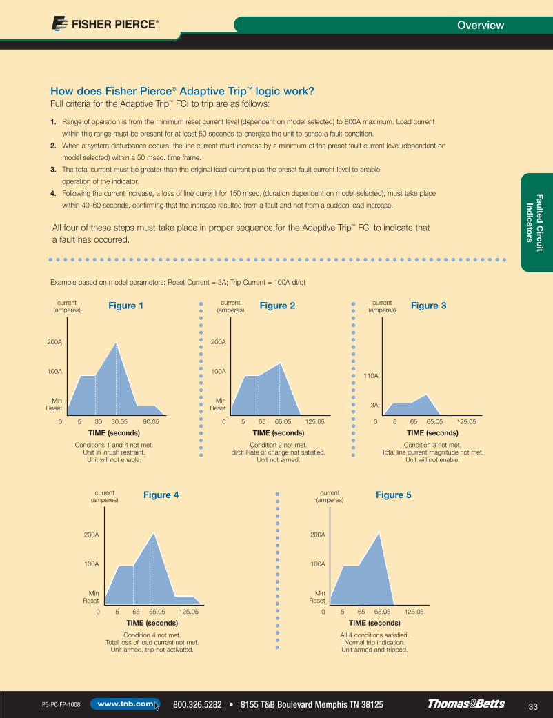
1. Range of operation is from the minimum reset current level (dependent on model selected) to 800A maximum. Load current
within this range must be present for at least 60 seconds to energize the unit to sense a fault condition.
2. When a system disturbance occurs, the line current must increase by a minimum of the preset fault current level (dependent on
model selected) within a 50 msec. time frame.
3. The total current must be greater than the original load current plus the preset fault current level to enable
operation of the indicator.
4. Following the current increase, a loss of line current for 150 msec. (duration dependent on model selected), must take place
within 40–60 seconds, confirming that the increase resulted from a fault and not from a sudden load increase.
How does Fisher Pierce® Adaptive Trip™ logic work?Full criteria for the Adaptive Trip™ FCI to trip are as follows:
All four of these steps must take place in proper sequence for the Adaptive Trip™ FCI to indicate that a fault has occurred.
Example based on model parameters: Reset Current = 3A; Trip Current = 100A di/dt
Figure 1 Figure 2 Figure 3
Figure 4 Figure 5
200A
100A
MinReset
0 5 30 30.05 90.05
TIME (seconds)
Conditions 1 and 4 not met.Unit in inrush restraint.
Unit will not enable.
current(amperes)
0 5 65 65.05 125.05
TIME (seconds)
Condition 2 not met.di/dt Rate of change not satisfied.
Unit not armed.
current(amperes)
0 5 65 65.05 125.05
TIME (seconds)
Condition 3 not met.Total line current magnitude not met.
Unit will not enable.
current(amperes)
0 5 65 65.05 125.05
TIME (seconds)
Condition 4 not met.Total loss of load current not met.
Unit armed, trip not activated.
current(amperes)
0 5 65 65.05 125.05
TIME (seconds)
All 4 conditions satisfied.Normal trip indication.
Unit armed and tripped.
current(amperes)
200A
100A
MinReset
110A
3A
200A
100A
MinReset
200A
100A
MinReset
0803_0357_tnb_FP_32&33 10/17/08 1:00 PM Page 33

8155 T&B Boulevard Memphis TN 38125 • 800.326.5282 PG-PC-FP-1008www.tnb.com34
OverviewFa
ulte
d C
ircu
itIn
dic
ato
rs
Which Fisher Pierce FCI is recommended for your application?
1580 1548 1547 1543 1542 1541 1516 1515 1514 TPMVF TPMVL TPMVOL TPMTL UCMTL OLMVOL OLMVF OLMVL OLMTL
Reference page 26 36 39 45 45 45 47 42 42 52 52 52 52 56 58 58 58 58
Overhead X X X X X X X X X
Underground X X X X X X X X X X X X
Padmounted Enclosure X X X X X X X X X X X X X
Residential/Secondary X X X X X X X
Sectionalizing Cabinet X X X X X
Close Proximity Enclosure
(3" center-to-center cables) X X X X X X X
Backfeed Restraint X X X X X X X
Inrush Restraint X X X X X X X X X X X X X X
Temporary Fault
Detection X
Directional Fault
Capability (Option) X
Neutral Current
(Cap. Banks) X
Phase(s) 1 1 1 3 2 1 1 3 1 1 1 1 1 1 1 1 1 1
Trip Logic
Fixed Current Trip X X X X X X X
Adaptive Trip X X
High/Low trip X X X X X X X X X
Reset Logic
Current X X
Voltage X X X X X X
Time X X X X X X X X X X X X X X
Manual X X X X X X X X X X X X X X X X X
Fault Indication
Options
LED X X X X X X X X X X X X X X X X
Fluorescent Flag X X X X X X
Flag & LED X X
Strobe Light X
Fiber Optic Display X X X X X X X X X X
Audible Alarm X X X
Radio Transmitter X X X X
SCADA Contacts X X X
Batteryless X X X
Options
0803_0357_tnb_FP_34&35 10/17/08 1:00 PM Page 34

PG-PC-FP-1008 800.326.5282 • 8155 T&B Boulevard Memphis TN 38125www.tnb.com 35
Overhead Faulted Circuit IndicatorsFaulted
Circuit
Indicato
rs
Reliable fault indication for single-phase overhead applications.Fisher Pierce® Series 1548 Overhead FCIs
FCIs with Radio Transmitters
Series 1548 radio FCIs can signal faults to handheld receivers, radio receivers and the
SmartLink™ Series 5000 cellular remote terminal unit (RTU) systems integrated with SCADA-
and web-based reporting systems. Status, alarms and other event notifications can be
integrated into SCADA systems, as well as sent to customer-designated personnel via e-mail,
pager or text message. Having precise fault information reduces outage duration, improves
system reliability and lowers operation costs.
Swipe Here
Trip/Reset Tool AT2186-10Manual trip/reset test for both permanent and temporary faultindication using hotstick-mountable reset tool.
Benefits/DescriptionsFeatures
Trip Logic Adaptive or fixed current trip with inrush restraint logic. Adaptive trip logic eliminates the
need for trip-rating selection or revision with changing load.
Reset Logic Automatic reset with return of load current and/or time reset of permanent fault indication.
Automatic time reset for temporary fault indication. Manual trip test and reset capabilities
using hotstick-mountable trip/reset tool.
Fault Indication Visual indication choices of LED, 5-LED Array, Flag or Strobe Light. Highly viewable 360º
indication (Strobe or LED). Radio fault reporting capability also available.
Mounting Hotstick mounting with automatic torque limiting.
Replaceable Lithium Battery Offers 10-year, maintenance-free service life. (Note that Flag model has non-replaceable
battery).
Supports a Wide Range of Conductors Mounts on conductors with diameters from 0.14" to 1.20" (3.56mm to 30.48mm).
Optional Features Available Options include temporary/permanent fault indication, instantaneous recloser coordination
feature and backfeed restraint using a delay-trip scheme (requires protective device to
pass two cycles minimum of fault current before closing).
0803_0357_tnb_FP_34&35 10/17/08 1:00 PM Page 35

8155 T&B Boulevard Memphis TN 38125 • 800.326.5282 PG-PC-FP-1008www.tnb.com36
Overhead Faulted Circuit IndicatorsFa
ulte
d C
ircu
itIn
dic
ato
rs
2.10(53.34)
11.80 Max.
4.75(120.65)
5.95(151.13)
1.25 (31.75)
.98 (24.892 )
2.525(64.135)
1.2 Cable Max
System Voltage
Flag, Strobe Models:44kV max.
LED, Radio Models:69kV max.
Continuous Withstand Load:1,000A max.
Operating Temperature:-40˚ C to 85˚ C
Reset Time Accuracy:±10% at 23˚ C
Current Reset:3A or 8A min. (model specific)
Fixed Trip Current Level:50 to 1,500A
Adaptive Trip:100 di/dt, 300 di/dt
Fault Withstand:25kA for 10 cycles (per ANSI/IEEE 495-1986)
Trip Accuracy:±10% at 23˚ C
Battery:Replaceable 10-yr. Lithium Cell (flag model non-replaceable)
Battery Operating Life at 23˚ C
Single Ultra Bright LED & Flag:1,000 operating hrs.
5 Red LED:400 operating hrs.
Strobe:120 operating hrs.
Radio with LED:800 operating hrs.
Temporary Fault Model
1 Amber (temporary fault) LED:1,500 operating hrs.
4 Red (permanent fault) LED:400 operating hrs.
Housing: Semi-conductive UV-stable polycarbonate
Cable Diameter: 0.14" to 1.2" (3.56mm to 30.48mm)
Certifications:Complies with ANSI/IEEEE 495-1986
Specifications
Mechanical Data(all dimensions in inches with millimeter equivalents in parentheses)
0803_0357_tnb_FP_36&37 10/17/08 1:01 PM Page 36

1 5 4 8 X H - X - X - X - 3 - X - X - A - X
PG-PC-FP-1008 800.326.5282 • 8155 T&B Boulevard Memphis TN 38125www.tnb.com 37
Overhead Faulted Circuit IndicatorsFaulted
Circuit
Indicato
rs
The following diagram shows how to construct a catalog number for the Series 1548 FCI.
Basic ModelF Standard offering, reclose dead time of
150 msec. (loss of current >150 msec.), 3Amin. load current required for reset, adaptiveand fixed inrush trip logic options available.
G Special application offering for temporaryfault detection where reclose recognitiontime of 32 msec. is required. Recommendedfor circuits with fast protection settingscapable of opening and reclosing in lessthan 10 cycles. Available with adaptive triplogic only. Requires 8A min. load currentrequired for reset. No current auto resetshould be specified. Transmitter Phase
EncoderA Phase AB Phase BC Phase CT TapN No transmitter available for
Options F, T, L of IndicatorOptions
Temporary FaultReset TimeA Temporary fault
not selected1 4 hrs.2 8 hrs.3 12 hrs.4 24 hrs.5 Manual reset
Trip/Inrush Logic OptionsAdaptive TripA Adaptive trip requires: 60 sec. continuous
min. load current; arming time <1⁄4 cyclefault current; loss of current within 60 sec.of fault current
B Same as A with 24ms ±20% delay trip(backfeed restraint)
Fixed TripC Inrush restraint active for 32 msec. from
power up, thereafter, undelayed trip curve±10% accuracy
D 32 msec. delayed trip ±20%, current trip±10% accuracy
U Undelayed current trip ±10% accuracy,standard trip
Trip/CurrentAdaptive TripN 100A di/dt adaptive trip*D 300A di/dt main feeder
applications**Fixed Trip0.5 50A1 100A2 200A3 300A4 400A5 500A6 600A8 800A10 1000A12 1200A15 1500A*100A at 20A load current to300A at 600A load current**300A at 20A load currentto 400A at 350A load current
Reset Time-DelayLED, Radio, Strobe, or FlagC 4-hr. automatic with current reset override (60 sec. after restoration of power)N 4-hr. automaticZ 60 seconds after restoration of power, otherwise no automatic resetP 24-hr. automaticT Manual reset only, most commonly used with flag model since batteries are not
used for indication. Requires tool AT2186-10
Factory Code
FactoryCode
CAT. NO. Description
1548FH-ANC3-L-N-A Branch Feeder (3A min. load, 100A increase within 50 msec. di/dt adaptive trip)1548FH-BDC3-L-N-A Main Feeder (3A min. load, 300A di/dt adaptive trip, 24 msec. delay for backfeed restraint)1548FH-BDC3-X-N-A-1 Temporary Fault Indication (3A min. load, 100A increase with 50 msec. di/dt adaptive trip); permanent fault indication with
4 hr. delay reset with 60 sec. current reset override, temporary fault indication with 8 hr. time delayed resetAccessories
AT2186-10 Manual test and reset toolA615 Battery for L optionA616 Battery for L, X and R optionsH2403-10 Battery renewal sticker
for Fisher Pierce® Series 1548 Overhead FCIsRecommended Models
Ordering Information
Indicates field that must be filled in to complete order.
NOTE: Availability of selected configuration will be verified at quotation time.
Indicator OptionsL Single ultra-bright LED (standard for
applications up to 69kV max.)J 5 ultra-bright LEDs for increased visibility
display (standard for applications up to69kV max.)
X Temporary fault indication option 4 red, 1amber LED (standard for applications upto 69kV max.)
T Strobe light (for applications up to 44kVmax.)
R Radio with single LED (for applicationsup to 69kV max.)
F Flag (for applications up to 44kV max.)
H Flag and LED (non-replaceable battery)(for applications up to 44kV max.)
0803_0357_tnb_FP_36&37 10/17/08 1:01 PM Page 37
Underground/Padmount Faulted Circuit Indicators
8155 T&B Boulevard Memphis TN 38125 • 800.326.5282 PG-PC-FP-1008www.tnb.com38
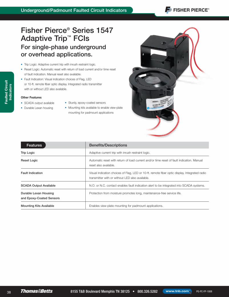
• Trip Logic: Adaptive current trip with inrush restraint logic.
• Reset Logic: Automatic reset with return of load current and/or time reset
of fault indication. Manual reset also available.
• Fault Indication: Visual indication choices of Flag, LED
or 10-ft. remote fiber optic display. Integrated radio transmitter
with or without LED also available.
Fisher Pierce® Series 1547 Adaptive Trip™ FCIsFor single-phase underground or overhead applications.
Other Features
• SCADA output available
• Durable Lexan housing
• Sturdy, epoxy-coated sensors
• Mounting kits available to enable view-plate
mounting for padmount applications
Faul
ted
Cir
cuit
Ind
icat
ors
Benefits/DescriptionsFeatures
Trip Logic Adaptive current trip with inrush restraint logic.
Reset Logic Automatic reset with return of load current and/or time reset of fault indication. Manual
reset also available.
Fault Indication Visual indication choices of Flag, LED or 10-ft. remote fiber optic display. Integrated radio
transmitter with or without LED also available.
SCADA Output Available N.O. or N.C. contact enables fault indication alert to be integrated into SCADA systems.
Durable Lexan Housing Protection from moisture promotes long, maintenance-free service life.
and Epoxy-Coated Sensors
Mounting Kits Available Enables view-plate mounting for padmount applications.
0803_0357_tnb_FP_38&39 10/17/08 1:01 PM Page 38

Underground/Padmount Faulted Circuit Indicators
PG-PC-FP-1008 800.326.5282 • 8155 T&B Boulevard Memphis TN 38125www.tnb.com 39
Faulted C
ircuitInd
icators
Operating Speed:Coordinates with properly applied current-limitingfuses, provided FCI trip-set and trip-releaseconditions are satisfied
Fault Withstand Capability:25kA for 10 cycles per ANSI/IEEE 495-1986
Operating Current Range:Min. reset current to 800A for trip operation
Continuous Current Rating:800A max.
Submersibility:Tested to 30 ft.
Reset Function:Resets to normal indication according to unit selected from Ordering Information Reset Delay Options
Reset Current Level:15⁄8" sensor with U-lamination: 1.0A23⁄16" sensor with U-lamination: 1.5A15⁄8" sensor w/o U-lamination: 2.0A23⁄16" sensor w/o U-lamination: 3.0A
Life Expectancy:(Series 1547A flag type) 20+ years
Rated Battery Life:800 hrs. of operation. Lithium cell,rated for 10-yr. life.(Series 1547B LED type; Series 1547C fiber optic type)
Line Current Adjust:Adjusts to line current 40–60 sec. after linecurrent exceeds min. reset current
Trip Operation:a) Trip Enable Condition: Occurs whenever linecurrent increases by the rate of 100A (or greater)within 3 cycles b) Trip Indication: FCI indicates trip only when linecurrent drops 0.5A above min. reset currentwithin 40–60 sec. after trip-set condition occurs
Approx. Shipping Weight:2.0 lbs.
Operating Temperature:-40˚ C to 85˚ C
Certifications:Complies with ANSI/IEEEE 495-1986
Specifications
Figure A — Indicator with Attached Sensor. Hotstick Mounting. Figure B — Indicator with Attached Sensor. Tie-Wrap Mounting.
Figure C — Bracket/Surface Mounting. Figure D — Window/Flush Mounting.
Figure E — Remote Sensor. Tie-Wrap Mounting.
Figure F — Remote Sensor. Hotstick Mounting.
Mechanical Data(all dimensions in inches with millimeter equivalents in parentheses)
0803_0357_tnb_FP_38&39 10/17/08 1:01 PM Page 39
1 5 4 7 A - P Z S M - A - N - R - A
8155 T&B Boulevard Memphis TN 38125 • 800.326.5282 PG-PC-FP-1008www.tnb.com40
Underground/Padmount Faulted Circuit IndicatorsFa
ulte
d C
ircu
itIn
dic
ato
rs
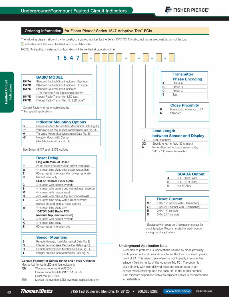
The following diagram shows how to construct a catalog number for the Series 1547 FCI. Not all combinations are possible; consult factory.
for Fisher Pierce® Series 1547 Adaptive Trip™ FCIs
BASIC MODEL1547A Standard Faulted Circuit Indicator Flag type1547B Standard Faulted Circuit Indicator LED type1547C Standard Faulted Circuit Indicator.
10-ft. Remote Fiber Optic cable display*1547D Integral Radio Transmitter LED type1547E Integral Radio Transmitter. No LED type**
Underground Application NoteA solution to problem FCI applications caused by close proximitycable placement and orientation is to set the loss of current operatepoint at 7A. This raised zero reference point greatly improves theadjacent field immunity of the Adaptive Trip FCI. The option isavailable only with time delayed reset and closed core U-lam sensor. When ordering, add the suffix “R” to the model number. A 3" minimum separation between adjacent cables is recommendedfor installation.
* Consult Factory for other cable lengths** For special applications
Indicator Mounting OptionsB Bracket/Surface Mount (See Mechanical Data Fig. C)P* Window/Flush Mount (See Mechanical Data Fig. D)M Tie-Wrap Mount (See Mechanical Data Fig. B)H* Hotstick Mount with Clamp
(See Mechanical Data Fig. A)
* See Series 1547A and 1547B options
Reset DelayFlag with Manual Reset
P 24-hr. reset time delay after power restorationW 4-hr. reset time delay after power restorationZ 60-sec. reset time delay after power restorationR Manual reset only
LED or Remote Fiber OpticC 4-hr. reset with current overrideE 4-hr. reset with current and manual reset overrideM 4-hr. reset with manual resetN 4-hr. reset with manual trip and manual resetT 4-hr. reset time delay with current override;
manual trip and manual reset overrideW 4-hr. reset time delay only
1547D/1547E Radio FCI (manual trip, manual reset)
J 4-hr. reset with current overrideK 4-hr. reset time delay Z 60-sec. reset time delay only
Sensor MountingS Remote tie-wrap (see Mechanical Data Fig. E)G Integral tie-wrap (see Mechanical Data Fig. B)H Remote hotstick (see Mechanical Data Fig. F)T Integral hotstick (see Mechanical Data Fig. A)
Consult Factory for Series 1547A and 1547B Options:Mechanical (for both LED and flag indicators)P(1): Window-mounting kit (AT2050-1)
Bracket-mounting kits (N1767-1, -2, -3)Reset tool (AT2186)
TRIP: Manual trip override (LED) (overhead applications only)
Reset CurrentM* 1.0A (15⁄8" sensor with U-lamination)L* 1.5A (2 3⁄16" sensor with U-lamination)B 2.0A (15⁄8" sensor)D 3.0A (2 3⁄16" sensor)
* Equipped with snap-on U-lamination sensor for circuit isolation. Recommended for padmount orunderground applications.
SCADA OutputA N.O. (10-ft. lead)B N.C. (10-ft. lead)N No SCADA
Lead Length between Sensor and Display
10 10 ft. (standard)XX Specify length in feet. (30 ft. max.)N None. Attached indicator sensor units,
“M” or “H” sensor termination
Close ProximityR Raised zero reference to 7AN Standard
Transmitter Phase Encoding
A Phase AB Phase BC Phase CT Tap
Ordering Information
Indicates field that must be filled in to complete order.
NOTE: Availability of selected configuration will be verified at quotation time.
0803_0357_tnb_FP_40&41 10/17/08 1:01 PM Page 40

PG-PC-FP-1008 800.326.5282 • 8155 T&B Boulevard Memphis TN 38125www.tnb.com 41
Underground/Padmount Faulted Circuit Indicators
Benefits/DescriptionsFeatures
Fisher Pierce® Series 1514/15 Current-Reset FCIsFor single-phase or three-phaseunderground or overheadapplications.
System Voltage:29.3 kV max
Trip Current:Factory preset from 50 to 1,500A
Trip Current Accuracy:± 10%
Trip Response Speed:Coordinates with properly applied current-limiting or expulsion fuses
Reset Current:Factory preset for 1.2, 1.5, 3.0 and 5.0A
Fault Withstand Capability:25 kA for 10 cycles per ANSI/IEEE 495-1986
Maximum Continuous Load Current:1,000A
Operating Temperature:- 40˚ C to 85˚ C
Submersibility:Tested to 30 ft.; exceeds ANSI/IEEE 495-1986
Life Expectancy:30+ years (flag type)
Rated Battery Life:10 years (long-life lithium cell)
Model 1514B/1515B — 800 hrs. ofoperation
Model 1514D — 300 hrs. of operation
Warranty:3 years
Certifications:Complies with ANSI/IEEEE 495-1986
Specifications
• Trip Logic: Adaptive current trip with inrush restraint logic.
• Reset Logic: Automatic reset with return of load current and/or time reset
of fault indication. Manual reset also available.
• Fault Indication: Visual indication choices of Flag, LED or 10-ft. remote fiber
optic display. Integrated radio transmitter with or without LED also available.
Other Features
• SCADA output available
• Durable Lexan housing
• Sturdy, epoxy-coated sensors
• Mounting kits available to allow view-plate
mounting for padmount applications
Trip Logic Fixed current trip with inrush restraint logic.
Reset Logic Automatic time reset with return of load current and/or time reset of fault indication.
Manual reset also available.
Fault Indication Visual indication choices of Flag, LED or 6-ft. remote fiber optic display. Integrated radio
transmitter with LED also available.
SCADA Output Available N.O. contact enables fault indication alert to be integrated into SCADA systems.
Durable Lexan Housing Protection from moisture promotes long, maintenance-free service life.
and Epoxy-Coated Sensors
Faulted C
ircuitInd
icators
0803_0357_tnb_FP_40&41 10/17/08 1:01 PM Page 41

8155 T&B Boulevard Memphis TN 38125 • 800.326.5282 PG-PC-FP-1008www.tnb.com42
Faul
ted
Cir
cuit
Ind
icat
ors
Underground/Padmount Faulted Circuit Indicators
Figure A — Indicator with Attached Sensor. Hotstick Mounting. Figure B — Indicator with Attached Sensor. Tie-Wrap Mounting.
Figure C — Bracket/Surface Mounting. Figure D — Window/Flush Mounting.
Figure E — Remote Sensor. Tie-Wrap Mounting.
Figure F — Remote Sensor. Hotstick Mounting.
Mechanical Data(all dimensions in inches with millimeter equivalents in parentheses)
0803_0357_tnb_FP_42&43 10/17/08 1:01 PM Page 42

Faulted C
ircuitInd
icators
PG-PC-FP-1008 800.326.5282 • 8155 T&B Boulevard Memphis TN 38125www.tnb.com 43
Underground/Padmount Faulted Circuit Indicators
1 5 1 4 S H - 8 A 3 - N T B - B - A
The following diagram shows how to construct a catalog number for the Series 1514 or 1515 FCI. Not all combinations are possible; consult factory.
Fisher Pierce® Series 1514/15 Current-Reset FCIs
Basic Model1514 Single-phase (one sensor, one indicator)1515 Three-phase (three sensors, one indicator)Unit requires current in all three phases to reset1514S/1515W
Flag display
1514A/ Flag display and single (N.O.) latching1515A* SCADA output contact1514B/1515B
LED Display (non-replaceable battery)
1514C/1515C
Remote, 6-ft. fiber optic LED display (requires "M" mounting)
1514D Integral Radio/LED display, requires hotstick mountingLED/Flag Display (non-replaceable battery), 1514H/inrush restraint only, remote bracket or panel-mount 1515Hunderground or hotstick overhead applications
1514M/1515M*
Flag display with momentary (N.O.) SCADA output
Underground Application NoteA solution to problem FCI applications, caused by close proximitycable placement and orientation, is to set the loss of current operatepoint at 7A. This raised zero reference point greatly improves theadjacent field immunity of the Adaptive Trip FCI. The option is availableonly with time delayed reset and closed core U-lam sensor. Whenordering, add the suffix “R” to the model number. A 3" minimumseparation between adjacent cables is recommended for installation.
*SCADA Contacts: 3.0A @ 125/250 VAC; 1/10 hp @ 250 VAC, 10-ft. cable length
Indicator Mounting OptionsB Bracket/surface mounting (remote from sensor)P(1) Window/flush mounting (remote from sensor)H(2) Hotstick mounting, attached indicator/sensor
(B and D sensors only, one phase only)M Tie-wrap mounting (attached indicator/sensors)
Consult factory for options: Manual reset tool (AT2186)(1) Special Lexan mounting kit (AT2050-1) for Code “P” mounting is available.(2) Special Lexan spacer (F2079) available for small (<1" dia.) conductor
overhead installation.
Inrush Restraint/Reset Delay OptionsFlag Display (1514A, 1514M, 1514S, 1515A, 1515M, 1515W),Manual Reset OverrideA Standard trip curve, 10 to 30-sec. delay after restoration of powerZ Inrush restraint, 60-sec. reset time delay after restoration of powerW Inrush restraint, 4-hr. reset time delay after restoration of powerN Inrush restraint, no automatic reset, manual reset onlyP Inrush restraint, 24-hr. reset time delay after restoration of powerLED Display (1514B, 1514C, 1514R, 1515B, 1515C, 1515R), Inrush RestraintW 4-hr. reset time delay after fault occurrenceC Same as W with current reset override upon energization of lineN Same as W with manual trip and manual reset overrideT Same as N with current reset overrideM Same as W with manual reset overrideE Same as C with manual reset overrideRadio Indication (1514D), Inrush Restraint, Manual Trip and ManualReset OverrideK 4-hr. reset time delay after fault occurrenceJ Same as K with current reset override upon energization of lineZ 60-sec. time delay after fault occurrence
Trip Setting0.5 50A1 100A2 200A3 300A4 400A6 600A8 800A10 1,000A12 1,200A15 1,500A
Minimum Reset Current Level1.2 1.2A (“M” sensor only)1.5 1.5A (“L” & “N” sensors only)3 3A
Lead Length between Sensor and Display
10 10 ft. (standard)XX Specify length in feet (30 ft. max.)N None. Attached indicator sensor units, “G”
or “T” sensor termination
Transmitter Phase EncodingA Phase A (1514D only)B Phase B (1514D only)C Phase C (1514D only)
Max. Cable DiameterB 15⁄8"D 2 3⁄16"K 2 5⁄16"M* 15⁄8"L* 2 3⁄16"N* 2 5⁄16"
Sensor TerminationS Terminates with remote lead connected to sensorT Sensor and indicator attached to hotstick clampH Hotstick clamp attached to sensor (15⁄8" and
2 3⁄16" sensors only)G Remote LED, removable fiber optic cable
Factory Code
Ordering Information
Indicates field that must be filled in to complete order.
NOTE: Availability of selected configuration will be verified at quotation time.
0803_0357_tnb_FP_42&43 10/17/08 1:01 PM Page 43

Trip Logic Fixed current trip with inrush delay.
Reset Logic Automatic time reset of fault indication. Manual reset also available.
Fault Indication Visual indication choices of LED with replaceable or non-replaceable battery.
Audible alarm fault indication with replaceable battery also available.
Optional Features Available Permanent or removable remote fiber optic display.
Benefits/DescriptionsFeatures
8155 T&B Boulevard Memphis TN 38125 • 800.326.5282 PG-PC-FP-1008www.tnb.com44
Faul
ted
Cir
cuit
Ind
icat
ors
Underground/Padmount Faulted Circuit Indicators
Fisher Pierce® Series 1541/42/43 Automatic Time Reset FCIsFor single-phase, two-phase or three-phase underground applications.
Three-Phase 1543
36(914.4)
36(914.4)
120(3048)
4.80(116.84)
1.90(48.26)
2.40(60.96)
3.25(82.55)
Mechanical Data(all dimensions in inches with millimeter equivalents in parentheses)
0803_0357_tnb_FP_44&45 10/17/08 1:02 PM Page 44

Faulted C
ircuitInd
icators
PG-PC-FP-1008 800.326.5282 • 8155 T&B Boulevard Memphis TN 38125www.tnb.com 45
Underground/Padmount Faulted Circuit Indicators
1 5 4 1 F H - 4 A - 1 0 R S - B
Fault Registration:Red, high-intensity LED with choice of hard-wired or fiber optic cable remote mounting or audibleintermittent beeper signal
Trip current:Factory preset to customer specifications withinrange of 50A and 100A to 1,500A in 100Aincrements
Trip Current Accuracy:±10% of trip rating (calibrated using 1" dia. cablefor 400A trip or less or 2.0" dia. cable for greaterthan 400A trip)
Trip Response Speed:Consult trip curves (coordinated to properly appliedlink, expulsion, power and current-limiting fuses)
Reset Time:4 hrs., 2 hrs., 1 hr., manual trip/reset standard
Overload Capacity:Capable of withstanding 25,000A for 10 cycles
Continuous Load Current:Rated at 1,000A max.
Temperature Range:-40˚ C to 85˚ C
Submersibility:Tested to 30 ft.
Operating Battery Life:800 hrs. for LED indication, 160 hrs. for audibleindication, both with 10-yr. life at 20˚ C
Battery:Long-life lithium cell
Cable Ranges:0.63" (16mm) to 1.58" (40mm); 1.58" (40mm) to 2.36" (60mm); 2.36" (60mm) to 3.55" (90mm)
Remote Fiber Optic Options:Permanent or removable (10 ft. standard,30 ft. max.)
Certifications:Complies with ANSI/IEEEE 495-1986
The following diagram shows how to construct a catalog number for Series 1541/1542/1543 FCIs. Not all combinations are possible; consult factory for ordering assistance.
for Fisher Pierce® Series 1541/42/43 Automatic Time Reset FCIs
Factory Code
Basic Model1541 Single-Phase1542 Two-Phase1543 Three-Phase
Inrush RestraintF Inrush time overcurrent
(dual curve) standardN Non-inrush delay
Indication/Battery OptionsH LED, non-replaceable battery, hotstick mountedR LED, replaceable battery, hotstick mountedA Audible alarm indication, replaceable battery,
hotstick mounted
Trip Point0.5 50A0.6 60A1 100A2 200A3 300A4 400A4.5 450A5 500A6 600A8 800A10 1000A12 1200A15 1500A
Cable Clamp SizeS Small, 0.63"–1.58" cable dia.M Medium, 1.58"–2.36" cable dia.L Large 2.36"–3.55" cable dia.
Reset Time Delay After Fault OccurrenceA 4-hr. automatic reset time delayB 2-hr. automatic reset time delayC 1-hr. automatic reset time delay
Length of Remote LED CableN Not applicable when code “T” is selected under
Display Options10 Remote LED, removable fiber optic cable
Display OptionsR Remote LEDT Integral LED or audible alarm (always
selected with code “A” or “H” underIndication/Battery Options)
E Remote LED, fiber optic cableF Remote LED, removable fiber optic cable
Specifications
Ordering Information
Indicates field that must be filled in to complete order.
NOTE: Availability of selected configuration will be verified at quotation time.
0803_0357_tnb_FP_44&45 10/17/08 1:02 PM Page 45
Benefits/DescriptionsFeatures
8155 T&B Boulevard Memphis TN 38125 • 800.326.5282 PG-PC-FP-1008www.tnb.com46
Faul
ted
Cir
cuit
Ind
icat
ors
Underground/Padmount Faulted Circuit Indicators
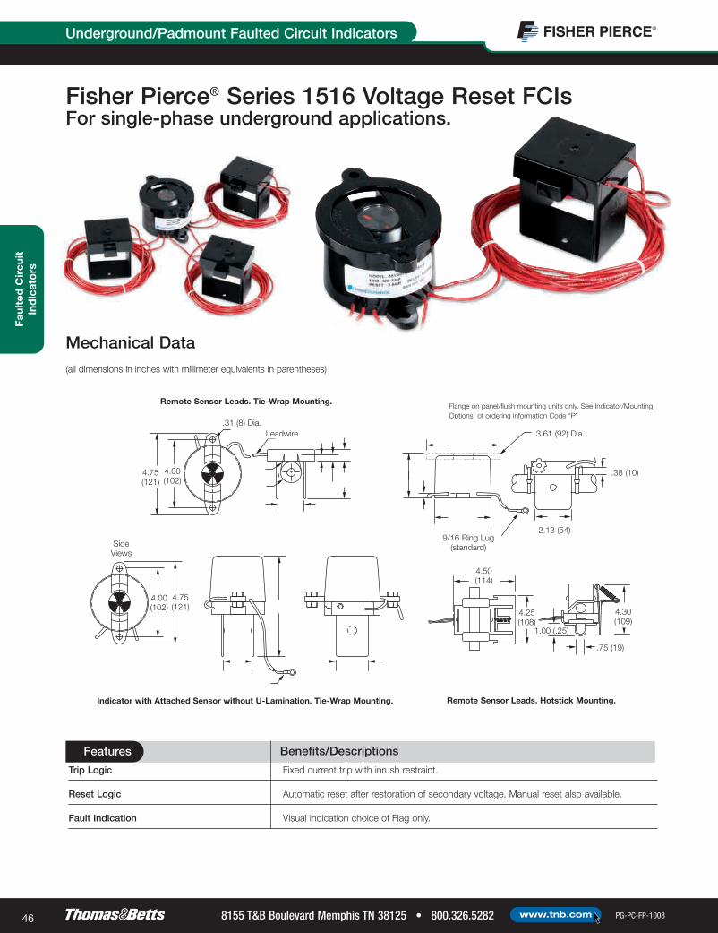
Fisher Pierce® Series 1516 Voltage Reset FCIsFor single-phase underground applications.
4.00(102)
4.75(121)
SideViews
4.75(121)
4.00(102)
.31 (8) Dia.
4.30(109)
9/16 Ring Lug(standard)
3.61 (92) Dia.
2.13 (54)
.38 (10)
1.00 (.25)
4.25(108)
4.50 (114)
Remote Sensor Leads. Tie-Wrap Mounting.
Remote Sensor Leads. Hotstick Mounting.Indicator with Attached Sensor without U-Lamination. Tie-Wrap Mounting.
Flange on panel/flush mounting units only. See Indicator/MountingOptions of ordering information Code “P”
Leadwire
.75 (19)
Trip Logic Fixed current trip with inrush restraint.
Reset Logic Automatic reset after restoration of secondary voltage. Manual reset also available.
Fault Indication Visual indication choice of Flag only.
Mechanical Data(all dimensions in inches with millimeter equivalents in parentheses)
0803_0357_tnb_FP_46&47 10/17/08 1:02 PM Page 46

Faulted C
ircuitInd
icators
PG-PC-FP-1008 800.326.5282 • 8155 T&B Boulevard Memphis TN 38125www.tnb.com 47
Underground/Padmount Faulted Circuit Indicators
Trip Current:Factory preset from 100 to 1,500A
Trip Current Accuracy:±10%
Trip Response Speed:Coordinates with properly applied current-limiting fuses
Reset Voltage (factory preset):120V Rating: 102V min.277V Rating: 235V min.
Max. Reset Response Time:60 sec.
Reset Lead Length:4 or 6 ft.
Life Expectancy:±20 yrs.
Fault Withstand Capability:25kA for 10 cycles per ANSI/IEEE 495-1986
Secondary Voltage Surge Withstand Capability:Conforms to ANSI/IEEE C62.41
Max. Continuous Load Current:1,000A
Operating Temperature:-40˚ C to 85˚ C
Submersibility: Tested to 20 ft.
Certifications:Complies with ANSI/IEEEE 495-1986
The following diagram shows how to construct a catalog number for Series 1516 FCIs. Not all combinations are possible; consult factory for ordering assistance and for information on available mounting kits and brackets.
for Fisher Pierce® Series 1516 Voltage-Reset FCIs
Basic Model1516 Automatic reset after restoration
of secondary voltage
Trip Sensitivity and OutputsS Standard sensitivity +10% with latching relayA Standard sensitivity +10% with latching relay
and SCADA output contacts (N.O.)
Indicator Mounting OptionsB Bracket/surface mounted (remote from sensor)P* Panel/flush mounted (remote from sensor)M Tie-wrap mounted (attached indicator/sensors)
* P Mounting Kit (2050-1)
Trip Curve/Reset TimeA StandardB Standard with inrush restraint
Reset Voltage Sensitivity1 120V nominal (102V minimum reset voltage) for use on 208 /120V
three-phase and 240/120V single-phase2 277V nominal (235V minimum reset voltage) for use on 480/277V
three-phase
Trip Current Setting1 100A2 200A2.5 250A3 300A4 400A5 500A6 600A8 800A10 1000A12 1200A15 1500A
Lead Length between Sensor and Display10 10 ft. (standard)XX Specify length in feet (30 ft. max.)N None. Attached indicator sensor units,
“G” sensor termination
Reset Voltage and Lead Length6 6 ft. (standard)XX Specify length in feet
(12 ft. max.)
Max. Cable DiameterB 15⁄8"D 2 3⁄16"K 2 5⁄16"
Sensor TerminationG Sensor attached to indicator,
tie-wrap mountS Terminates with remote
lead-connected sensorH Hotstick clamp attached to sensor
(“B” & “D” sensors only)
Factory Code
Specifications
Ordering Information
Indicates field that must be filled in to complete order.
NOTE: Availability of selected configuration will be verified at quotation time.
1 5 1 6 A B - 2 A 1 1 0 S B 6 B
0803_0357_tnb_FP_46&47 10/17/08 1:02 PM Page 47

8155 T&B Boulevard Memphis TN 38125 • 800.326.5282 PG-PC-FP-1008www.tnb.com48
Faul
ted
Cir
cuit
Ind
icat
ors
Underground/Padmount Faulted Circuit Indicators
Fisher Pierce® Model 16514AM-45102 SmartNet™ Directional Network FCIFor single-phase underground applications.
To order Fisher Pierce® Model 16514AM-45102 SmartNet™ Directional Network FCIs, please contact the factory.
for Fisher Pierce® Model 16514AM-45102 SmartNet™ Directional Network FCI
Operation
• Max. operational current: 25kA per ANSI 495
• Max. current withstand: 40kA for 10 cycles with no damage
• When the feeder is energized, the unit’s control algorithm initiates a settling period to
allow unwanted transients to dampen. After the settling period is satisfied, a phase
relationship is learned, stored and considered normal power flow. When the trip
current is sensed, the phase angle is compared to the learned phase angle and, if
within the pre-determined phase relationship, is considered a valid fault.
Ordering Information
Figure A — Indicator with Attached Sensor. Hotstick Mounting. Figure B — Indicator with Attached Sensor. Tie-Wrap Mounting.
Figure C — Bracket/Surface Mounting. Figure D — Window/Flush Mounting.
Figure E — Remote Sensor. Tie-Wrap Mounting. Figure F — Remote Sensor. Hotstick Mounting.
Trip Logic Programmable fixed-current trip.
Reset Logic Automatic reset of fault indication; manual reset also available.
Fault Indication Visual indication choice of LED only.
Benefits/DescriptionsFeatures
Mechanical Data(all dimensions in inches with millimeter equivalents in parentheses)
0803_0357_tnb_FP_48&49 10/17/08 1:02 PM Page 48

Faulted C
ircuitInd
icators
PG-PC-FP-1008 800.326.5282 • 8155 T&B Boulevard Memphis TN 38125www.tnb.com 49
Cellular RTU for Faulted Circuit Indicators
Fisher Pierce® SmartLink™ Series 5000 CellularRTU for Fisher Pierce® FCIs
The Fisher Pierce® SmartLink™ Series 5000 integrated cellular
Remote Terminal Unit (RTU) provides reliable and cost-effective two-way
communication for automated fault reporting from Fisher Pierce® Series 1548
radio FCIs. Electric utility operations personnel can have precise fault alarms
and data fed to a variety of applications in seconds, increasing response time
and system reliability.
The SmartLink™ Series 5000 RTU uses technology from Telemetric to communicate
over the digital or analog cellular data networks, with coverage available to over 98% of
the population in North America. No additional radio equipment, license or local cellular
account is required. The SmartLink™ Series 5000’s intelligent processor provides flexible reporting of permanent
and temporary fault conditions. Utilities can access a secure, web-based fault-reporting application or integrate
automatic fault reporting into SCADA/EMS systems using optional software from Telemetric.
The secure, web-based application displays device data that can be queried or polled remotely. A variety
of user-specified fault alarms can be configured to notify a designated person of a reported event by e-mail,
pager or text message.
Reliable, cost-effective, two-way communication for fault reporting.
Benefits/DescriptionsFeatures
Uses local RF signal Reports fault alarms from up to four Series 1548 radio FCIs (A, B, C phase + tap),
located up to 100 feet away
Immediate Reporting of Alarm Conditions Provides instant notification of: Permanent fault on any phase, phase status; fault-cleared
status by phase; overvoltage or undervoltage setpoints on control power phase; and low
battery alarm.
Immediate or Off-Peak Reporting User-configurable to receive instant notification of momentary fault data or wait for
of Momentary Fault Data lower-cost off-peak hours.
Nationwide GPRS Support Communicates over cellular data networks via Cingular Wireless and affiliated roaming
partners with a variety of application data plans, with coverage available to more than 98%
of the North American population.
RTU Status-Point Querying Available at any time through the web-based application or by SCADA/EMS using optional
Telemetric™ SCADA-Xchange™ software.
RTU Battery-Status Check Sent automatically to ensure continuous, reliable operation.
and Low-Battery Alarms
0803_0357_tnb_FP_48&49 10/17/08 1:02 PM Page 49

8155 T&B Boulevard Memphis TN 38125 • 800.326.5282 PG-PC-FP-1008www.tnb.com50
Faul
ted
Cir
cuit
Ind
icat
ors
Cellular RTU for Faulted Circuit Indicators
RTU/SCADASystem
How Radio FCIs help locate and report faults.Helps crews locate faults easily when fault indicators are not directly visible.
Designed for distributionRTU/SCADA overhead systems
Utility Control Room
Cell Tower
No Utillity
Communication
Infastructure Required
SmartLink™ 50001548 FCI In Field Location
1560-1
Handheld Receiver
1560-2, -3, -4
Fixed-Mount Receiver
0803_0357_tnb_FP_50&51 10/17/08 1:02 PM Page 50

PG-PC-FP-1008 800.326.5282 • 8155 T&B Boulevard Memphis TN 38125www.tnb.com 51
Cellular RTU for Faulted Circuit IndicatorsFaulted
Circuit
Indicato
rs
Fault Indicator Receiver
Operating Frequency:312 MHz
Receiver Range:100 ft. min. typical
Receiver Sensitivity Adjustment:Selectable via local configuration or web application to max. range of local RF radio (low gain, high gain)
Certification:Complies with FCC part 15 emissions
Cellular Radio Technology
Dual-band, dual-mode supporting GSM/GPRS 850/1900 MHz; nationwide GPRS support via Cingular Wireless and affiliated roaming partners with a variety of application data plans
Transmit Power:0.6 to 1.2W
External mounted antenna, flexible dual-band (850/1900) cellular, SMA(F) connector
Fault receiver antenna (312 MHz RF system, BNC connector)
Measurement Points List - Calls & Polling
• Permanent fault status indication from radio FCI
• Control Power Voltage Measurements: Undervoltage/Overvoltage Value Alarm
• Control Power Status (Outage)
• Battery Status
• Temporary Fault Data
• Time Scheduled Calls
• Alarm Calls (permanent fault, clearing, phase status, low battery)
• Polling of all status and analog points
Intelligent Web Server
• Data is secure and password protected
• Server authentication using 128-bit encryption key validation
• E-mail, text message or pager notification options
Local Serial PortRS-232 communications port for local configuration.Windows-based configuration software included with RTU
Front-Panel LED Indicators
Qty. Color Label (Indication)
1 Green Cellular Communication Present
1 Green Processor OK
4 Red Fault Received (A, B, C and Tap)
1 Tri-Color Radio Signal Strength Indicator
Electrical/Environmental
Operating Voltage:95 – 135 VAC, 60Hz
Surge Withstand:ANSI/IEEE C37.90.1-2002, 4kV min.@ 1.2/50 µs surge
FNM style Slo-Blo® fuse, barrel-mounted
Operating temperature range:-40˚ C to 70˚ C
Battery Backup
Standard:Lead Acid, rechargeable 12V (3 to 5 yrs. expected service life)
Carryover Time:4-hr. typical, 3-hr. min.
Recharge Time after 3–4-hr. Carryover:6 hrs. typical
Accessibility:Front-panel replaceable.
Status message sent weekly or by request.
Enclosure
Lexan enclosure for meter socket mounting
NEMA 3R Rating
Security latch for meter seal or 3⁄8" hasp padlock
Specifications
0803_0357_tnb_FP_50&51 10/17/08 1:02 PM Page 51

8155 T&B Boulevard Memphis TN 38125 • 800.326.5282 PG-PC-FP-1008www.tnb.com52
Faul
ted
Cir
cuit
Ind
icat
ors
Receivers for FCIs
for Fisher Pierce® SmartLink™ 5000 Cellular RTU and Radio ReceiversOrdering Information
CAT. NO. DESCRIPTION3175B0126G1 SmartLink™ 5000 Cellular RTU (includes battery back-up and antennas)1560-1 Handheld Receiver with audible and LED indicator1560-2 RTU/SCADA Radio Receiver with 3 dry contact outputs for Phase A, B and C (includes mounting bracket)1560-3 RTU/SCADA Radio Receiver with 1 dry contact output for Phase A, B or C (includes mounting bracket)1560-4 RTU/SCADA Radio Receiver with 4 dry contact outputs for Phase A, B, C and tap (includes mounting bracket)
1560-1
Handheld Receiver1560-2, -3, -4
Fixed-Mount Receiver
Fisher Pierce® Series 1650Receivers for FCIsDrive-By FCI Status.
Specifications
Frequency:312 MHz
Range:100 ft. max.
Power:9V battery
Handheld
Complies with FCC Part 15 emissions
Specifications
Frequency:312 MHz
Range:100 ft. max.
Power:9–12 VDC, 20mA external
Complies with FCC Part 15 emissions
0803_0357_tnb_FP_52&53 10/17/08 1:03 PM Page 52

PG-PC-FP-1008 800.326.5282 • 8155 T&B Boulevard Memphis TN 38125www.tnb.com 53
Test Point Fault IndicatorsFaulted
Circuit
Indicato
rs
Mount directly to any IEEE 386 standard capacitive test point.
Fisher Pierce® TPM Series Test Point Fault Indicators
AccQTrip™ Logic Circuitry Prevents false indications in voltage-reset units due to inrush currents, cold load pickup
and overloading.
High/Low Trip-Setting Selection Requires no minimum load current and no load surveys.
Internal Magnetic Shielding Prevents adjacent phase effects.
1 msec. Trip Response Coordinates with current-limiting fuses, as well as other protection devices
Magnetically Latched Flag Prevents flag indication from changing state due to shock or vibration.
Test Point Mounting Mounts directly to 200 and 600 amp elbows, splices and other cable accessories
equipped with IEEE 386 standard capacitive test points from Fisher Pierce™
and other manufacturers.
Built-In Pulling Eye Enables safe, easy hotstick installation and removal from test points.
Durable Construction Enclosed in a rugged, yet lightweight and compact, sealed, impact- and corrosion-
resistant Lexan housing with EPDM molded-rubber test point mounting boot.
Fisher Pierce® Test Point Mounted Fault Indicators consist of a solid-state current sensor
connected to a faulted-circuit display, providing a clear visual means for quickly locating faulted
cables and equipment on underground distribution systems.
Designs incorporate advanced circuit logic and monitoring system protection operation to
prevent the indicator from tripping unless an overcurrent condition is followed by a loss of system
voltage. Trip and reset operations are automatic, and for versatility and convenience, the same
indicator may be used for 5KV thru 35KV applications.
Basic OperationA faulted circuit produces an associated magnetic field, which closes a reed switch in the indicator, resulting in a tripped display. Trip response
occurs in .001 seconds (1 msec.), allowing the fault indicator to properly coordinate with all types of circuit-protection schemes, including current-
limiting fuses. To eliminate confusing false trips, voltage-reset indicators are equipped with inrush, backfeed, overload and cold-load pick-up restraint
circuitry. Current sensors feature internal shielding to prevent inadvertent tripping when located in close proximity to adjacent phases, such as
in junction-mounted applications.
Benefits/DescriptionsFeatures
0803_0357_tnb_FP_52&53 10/17/08 1:03 PM Page 53

8155 T&B Boulevard Memphis TN 38125 • 800.326.5282 PG-PC-FP-1008www.tnb.com54
Test Point Fault IndicatorsFa
ulte
d C
ircu
itIn
dic
ato
rs
Faulted-Circuit Operationt1 Fault Indicator is connected to the system
and powers up. At 5kV, this takes 3 minutes
for the test point mounted unit and 6 minutes
for the overhead type unit. At higher voltages,
power-up time is shorter.
t2 Fault current is detected. Fault Indicator is armed
after 1 msec. Fault Indicator display shows Normal.
t3 Breaker/recloser locks out and voltage drops.
t4 Voltage is lost. A 30-second time window
allows for the protective device to clear the
fault and reclose. Indicator changes state.
Inrush-Restraint Operationt1 Fault Indicator is connected to the system and
powers up. At 5kV, this takes 3 minutes for the test
point mounted unit and 6 minutes for the overhead
type unit. At higher voltages, power-up time is shorter.
t1–t2 Upline recloser/breaker operation due to fault on
another phase. After 100 msec. (t2), the Fault
Indicator is disabled because no fault current is
detected.
t3 Recloser closes back. Voltage is back to normal.
Unfaulted phases see inrush. No change in the Fault
Indicator display.
Overloading Operationt1 Fault Indicator is connected to the system and
powers up. At 5kV, this takes 3 minutes for the test
point mounted unit and 6 minutes for the overhead
type unit. At higher voltages, power-up time is shorter.
t2 Device downline from Fault Indicator switches,
creating an overload. Fault Indicator is armed after
1msec. Fault Indicator display shows Normal.
t3 Overload condition over. Fault Indicator
does not change state.
t4 After 30 seconds, Fault Indicator
goes back to initialized state.
(1 ms Trip Response) (30 second window)
SystemVoltage
PrimaryCurrent
Fault IndicatorStatus
FaultIndicatorDisplayStatus
SystemVoltage
PrimaryCurrent
Fault IndicatorStatus
FaultIndicatorDisplayStatus
SystemVoltage
PrimaryCurrent
Fault IndicatorStatus
FaultIndicatorDisplayStatus
0803_0357_tnb_FP_54&55 10/17/08 1:03 PM Page 54

PG-PC-FP-1008 800.326.5282 • 8155 T&B Boulevard Memphis TN 38125www.tnb.com 55
Nominal Voltage4.16-60kV (L-L)
Nominal Trip RatingsLow, 400 Amp; High, 800 Amp
Trip Response Time1mS
Fault Clearing Time1
.001 – 30 Seconds Subsequent to Arming
Maximum Surge Level25kA 10 Cycles 60 Hz
Effect of Adjacent PhaseInternal Shielding Prevents AdjacentPhase Effects
Inrush/Backfeed Restraint100mS (Disable Delay)
Load Current RequirementsNone
Power Up Requirement3 Minutes @ 5kV
Display TypeFlashing Super Bright LED
Flash Rate30 Flashes per Minute
LED Display Time4 Hour – Standard
Reset Time4 Hour – Standard (longer timesavailable upon request)
Power Source3
3.6 Volt Lithium Thyonil ChlorideBattery
Battery Capacity2.4 Ah
Battery Operating Life1200 Flash Hours Minimum
Battery Storage Life15-20 Years
Temperature Range-40º C to 85º C
Housing MaterialMounting Boot – EPDM Conductive RubberHousing Body – UV StabilizedPolycarbonate Polymer
Weight258 Grams
CertificationsComplies with ANSI/IEEEE 495-1986
Nominal Voltage4.16-60kV (L-L)
Nominal Trip RatingsLow, 400 Amp; High, 800 Amp
Trip Response Time1mS
Fault-Clearing Time1
.001 – 30 Seconds Subsequent to Arming
Maximum Surge Level25kA 10 Cycles 60 Hz
Effect of Adjacent PhaseInternal Shielding Prevents AdjacentPhase Effects
Inrush Restraint Response100mS (Disable Delay)
Load Current RequirementsNone
Display TypeMechanical Flag
Minimum Reset Voltage5kV (Beginning InitializingSequence)
Voltage Reset Time3 Minutes @ 5kV
Power SourceVolt Test Point Powered
Temperature Range-40º C to 85º C
Housing MaterialMounting Boot – EPDM Conductive Rubber Housing Body – UV Stabilized Polycarbonate Polymer
Weight258 Grams
Certifications:Complies with ANSI/IEEEE 495-1986
Specifications
Specifications for TPM Voltage Reset,Flag Display: Model TPMVF
Specifications for TPM Voltage Operated,Time Reset, LED Display: Model TPMVOL
Nominal Voltage4.16-60kV (L-L)
Nominal Trip RatingsLow, 400 Amp; High, 800 Amp
Trip Response Time1mS
Fault Clearing Time1
.001 – 30 Seconds Subsequent to Arming
Maximum Surge Level25kA 10 Cycles 60 Hz
Effect of Adjacent PhaseInternal Shielding Prevents AdjacentPhase Effects
Inrush Restraint Response100mS (Disable Delay)
Load Current RequirementsNone
Power Up Requirement3 Minutes @ 5kV
Display TypeFlashing Super Bright LED
Flash Rate30 Flashes per Minute
LED Display Time4 Hour – Standard
Voltage Reset Time6 Minutes @ 5kV
Power Source3
3.6 Volt Lithium Thyonil ChlorideBattery
Battery Capacity2.4 Ah
Battery Operating Life1200 Flash Hours Minimum
Battery Storage Life15-20 Years
Temperature Range-40º C to 85º C
Housing MaterialMounting Boot – EPDM Conductive Rubber Housing Body – UV StabilizedPolycarbonate Polymer
Weight:258 Grams
Certifications:Complies with ANSI/IEEEE 495-1986
Specifications for TPM Voltage Reset,LED Display: Model TPMVL
Nominal Voltage4.16-60kV (L-L)
Nominal Trip RatingsLow, 400 Amp; High, 800 Amp
Trip Response Time1mS
Maximum Surge Level25kA 10 Cycles 60 Hz
Effect of Adjacent PhaseInternal Shielding PreventsAdjacent Phase Effects
Power Up RequirementNone
Display TypeFlashing Super Bright LED
Flash Rate30 Flashes per Minute
Reset Time4 Hour – Standard
Power Source3
3.6 Volt Lithium Thyonil ChlorideBattery
Battery Capacity2.4 Ah
Battery Operating Life1200 Flash Hours Minimum
Battery Storage Life15-20 Years
Temperature Range-40º C to 85º C
Housing MaterialMounting Boot – EPDM Conductive Rubber Housing Body – UV StabilizedPolycarbonate Polymer
Weight258 Grams
Certifications:Complies with ANSI/IEEEE 495-1986
Specifications for TPM Time Reset,LED Display: Model TPMTL
Specifications
Test Point Fault IndicatorsFaulted
Circuit
Indicato
rs
Specifications
Specifications
1. Prevents false trips due to short time interruptions without loss of voltage.
2. Inrush restraint is standard on voltage reset models. It is not available on the timereset models.
3. Battery powers LED and it is active only when LED is ON. Lithium Thyonil Chloridebatteries provide accurate indication throughout the entire temperature range.
0803_0357_tnb_FP_54&55 10/17/08 1:03 PM Page 55

8155 T&B Boulevard Memphis TN 38125 • 800.326.5282 PG-PC-FP-1008www.tnb.com56
Test Point Fault IndicatorsFa
ulte
d C
ircu
itIn
dic
ato
rs
CAT. NO. DESCRIPTION
TPMTL-[ _ ] Time Reset with LED Display (auto-resets to normal after 4 hrs.; may also be manually reset using an FTT test tool)TPMVF-[ _ ] Voltage Reset with Flag Display (auto-resets to normal after system voltage restoration; reset requires 5kV min. voltage
with time required for reset proportional to system voltage)TPMVL-[ _ ] Voltage Reset with LED Display (auto-resets to normal after system voltage restoration; reset requires 5kV min. voltage
with time required for reset proportional to system voltage)TPMVOL-[ _ ] Voltage Operated, Time Reset, LED Display (auto-resets after 4 hrs.; longer time resets available upon request)
CAT. NO. SUFFIX DESCRIPTION
-LT For 200A. All fused taps use LOW trip rating. For URD applications, use LOW trip rating.-HT For 600A. For URD applications, use HIGH trip rating.
Pulling Eyefor HotstickInstallationand Removal
FaultedCircuitDisplay
Test Point
Test Point Mounting Plug
for Fisher Pierce® TPM Series Test Point Fault IndicatorsOrdering Information
Mechanical Data(all dimensions in inches with millimeter equivalents in parentheses)
37⁄8(98)
11⁄8(29)13⁄8(35)
21⁄4(57)
31⁄4(83)
NOTE: For overhead bulk feeder applications, use HIGH or LOW trip ratings (whichever is greater than the minimum pickup setting of the related protection device).
AccQTrip™ and AccQClamp™ are trademarks of Quality Indications, Inc.
0803_0357_tnb_FP_56&57 10/17/08 1:03 PM Page 56

PG-PC-FP-1008 800.326.5282 • 8155 T&B Boulevard Memphis TN 38125www.tnb.com 57
Underground Clamp Type Fault IndicatorsFaulted
Circuit
Indicato
rs
TYPICAL INSTALLATION
As shown, proper installation of VCM cable mounted
fault indicators requires routing cable neutral wires to
prevent the ground return from affecting trip accuracy.
Similar procedures should be followed for tape, wire,
LC or other types of shielded cable constructions.
Install Fault Indicator in Area Shown
Do not install indicator directly over the concentric neutral to avoid misindication (Fig. 4).
Fig. 1 Fig. 2 Fig. 3 Fig. 4
Self-powered Fisher Pierce® UCM Series Underground Clamp Type Fault Indicators
consist of a solid-state current sensor connected to a faulted circiut display. Units
are designed for direct installation to an underground power cable using a spring-
loaded, over-center toggle clamp mounting provision. The clamp accommodates
cables ranging from .4" to 2.2" diameter and includes retainer pads to prevent slip
and twist. The clamp positions the cable conductor at a constant distance from the current sensor, maintaining
indicator trip accuracy over the entire range of cable sizes. Designs feature compact, shielded and sealed, corrosion-
resistant construction. The indicator is enclosed in a durable, impact-resistant Lexan® housing and includes a built-in pulling eye
for easy hotstick installation and removal from the cable.
Fisher Pierce® UCM Series UndergroundClamp Type Fault Indicators
Basic OperationA faulted circuit produces an associated magnetic field, which closes a reed
switch in the indicator, resulting in a tripped display. Trip response occurs in
.001 seconds, allowing the fault indicator to properly coordinate with all
types of circuit protection schemes including current-limiting fuses.
Series VCM fault indicators are constructed with an internally shielded
current sensor that prevents inadvertent tripping when located in close
proximity to adjacent phases, such as junction-mounted applications.
Spring-LoadedMounting Clamps
Provision for HotstickInstallation and Removal
Faulted Circuit Display
Benefits/DescriptionsFeatures
AccQClamp™ Mounting Provision Universal one-size-fits-all design automatically adjusts.
High/Low Trip Setting Selection No minimum load current requirement and no load surveys needed.
Trip Response of .001 Seconds Coordinates with current-limiting fuses, as well as other protection devices.
Internal Magnetic Shielding Prevents adjacent phase effects.
Locate faulted cables and equipment onunderground distribution systems.
0803_0357_tnb_FP_56&57 10/17/08 1:03 PM Page 57

8155 T&B Boulevard Memphis TN 38125 • 800.326.5282 PG-PC-FP-1008www.tnb.com58
Underground Clamp Type Fault IndicatorsFa
ulte
d C
ircu
itIn
dic
ato
rs
NOTES:
1) Battery powers LED and it is active only when LED is ON. Lithium ThyonilChloride batteries provide accurate indication throughout the entire temperaturerange.
Specifications for UCM Time-Reset,LED Display: Model UCMTL
Nominal Voltage4.16-60kV (L-L)
Nominal Trip RatingsLow, 400 Amp; High, 800 Amp
Trip Response Time1mS
Maximum Surge Level25kA 10 Cycles 60 Hz
Effect of Adjacent PhaseInternal Shielding Prevents Adjacent PhaseEffects
Display TypeFlashing Super Bright LED
Flash Rate30 Flashes per Minute
Reset Time4 Hour - Standard
Power Source1
3.6 Volt Lithium Thyonil Chloride Battery
Battery Capacity2.4 Ah
Battery Operating Life1200 Flash Hours Minimum
Battery Storage Life15-20 Years
Temperature Range-40º C to +85º C
Housing MaterialMounting Boot – EPDM Conductive Rubber
Housing Body – UV Stabilized PolycarbonatePolymer
Weight258 Grams
CertificationComplies with ANSI/IEEEE 495-1986
time/current curve for UCMTL Trip Point VS. Cable Diameter
Specifications
CAT. NO. PREFIX DESCRIPTION
UCMTL Time Reset with LED Display (Indicator auto-resets to normal after a four hour time duration. Indicator may also be
manually reset using an FTT test tool.)
CAT. NO. SUFFIX DESCRIPTION
LT All fused taps use LOW trip rating. For 200 amp circuits. URD applications, use LOW trip rating.HT For 600 amp. circuits. URD Applications, use high trip rating.
for Fisher Pierce® UCM Series Underground Clamp Type Fault IndicatorsOrdering Information
NOTE: For overhead bulk feeder applications, use HIGH or LOW trip ratings (whichever is greater than the minimum pickup setting of the related protection device).
AccQTrip™ and AccQClamp™ are trademarks of Quality Indications, Inc.
41⁄4"108mm
open21⁄4"
57mm
55⁄8"143mm
open
23⁄8"60mmopen
37⁄8"98mm
41⁄4"108mm
11⁄8" 29mm
11⁄8" 29mm
0803_0357_tnb_FP_58&59 10/17/08 1:03 PM Page 58

PG-PC-FP-1008 800.326.5282 • 8155 T&B Boulevard Memphis TN 38125www.tnb.com 59
Overhead Line Fault IndicatorsFaulted
Circuit
Indicato
rs
Fisher Pierce® Series OLMOverhead Line Fault Indicators
A faulted circuit produces a magnetic field, which closes a reed switch in the indicator
and causes a tripped display. A trip response time of .001 seconds enables the indicator
to properly coordinate with all circuit-protection schemes, including current-limiting fuses.
To eliminate confusing false trips, indicators feature inrush, overload and cold-load pick-
up restraint circuitry as standard. Internal shielding of current sensors prevents inadvertent
tripping when in close proximity to adjacent phases.
Basic Operation
Self-powered Fisher Pierce® Series OLM Overhead Line Fault Indicators consist of a solid-
state current sensor connected to a faulted circuit display. Advanced circuit logic monitors
system protection operation and prevents indicator tripping unless an overcurrent
condition is followed by a loss of system voltage. Trip and reset operations are automatic,
and the same indicator may be used for 5kV thru 35kV line-to-ground applications.
These compact, sealed and corrosion-resistant units are designed for direct installation to
an overhead line using a spring-loaded, over-center toggle clamp. Equipped with retainer
pads to prevent slip and twist, the clamp positions the conductor at a constant distance
from the current sensor, maintaining trip accuracy over the entire conductor diameter
range of .4" to 2.2".
Time/current Curve for OLMVF, VL, VOL, TL Trip Point VS. Cable Diameter
41⁄4"108mm
open21⁄4"
57mm
55⁄8"143mm
open
23⁄8"60mmopen
37⁄8"98mm
41⁄4"108mm
11⁄8" 29mm
11⁄8" 29mm
Locate faulted circuits and equipmenton overhead distribution systems.
Benefits/DescriptionsFeatures
AccQTrip™ Logic Circuitry In voltage reset units prevents false indications due to inrush currents, cold load pickup
and overloading.
AccQClamp™ Mounting Provision Universal one-size-fits-all design automatically adjusts.
High/Low Trip Setting Selection No minimum load current requirement and no load surveys needed.
Trip Response of .001 Seconds Coordinates with current-limiting fuses, as well as other protection devices.
Internal Magnetic Shielding Prevents adjacent phase effects.
Magnetically Latched Flag Indication Flag indication will not change states due to shock or vibration.
Lightweight Enclosure Compact and sealed
0803_0357_tnb_FP_58&59 10/17/08 1:03 PM Page 59

8155 T&B Boulevard Memphis TN 38125 • 800.326.5282 PG-PC-FP-1008www.tnb.com60
Overhead Line Fault IndicatorsFa
ulte
d C
ircu
itIn
dic
ato
rs
Nominal Voltage4.16-60kV (L-L)
Nominal Trip RatingsLow, 400 Amp; High, 800 Amp
Trip Response Time1mS
Fault Clearing Time1
.001 – 30 Seconds Subsequent to Arming
Maximum Surge Level25kA 10 Cycles 60 Hz
Effect of Adjacent PhaseInternal Shielding Prevents AdjacentPhase Effects
Inrush/Backfeed Restraint100mS (Disable Delay)
Load Current RequirementsNone
Power Up Requirement6 Minutes @ 5kV
Display TypeFlashing Super Bright LED
Flash Rate30 Flashes per Minute
LED Display Time4 Hour – Standard
Reset Time4 Hour – Standard (longer timesavailable upon request)
Power Source3
3.6 Volt Lithium Thyonil ChlorideBattery
Battery Capacity2.4 Ah
Battery Operating Life1200 Flash Hours Minimum
Battery Storage Life15-20 Years
Temperature Range-40º C to 85º C
Housing MaterialMounting Boot – EPDM Conductive RubberHousing Body – UV StabilizedPolycarbonate Polymer
Weight258 Grams
CertificationsComplies with ANSI/IEEEE 495-1986
Nominal Voltage4.16-60kV (L-L)
Nominal Trip RatingsLow, 400 Amp; High, 800 Amp
Trip Response Time1mS
Fault-Clearing Time1
.001 – 30 Seconds Subsequent to Arming
Maximum Surge Level25kA 10 Cycles 60 Hz
Effect of Adjacent PhaseInternal Shielding Prevents AdjacentPhase Effects
Inrush Restraint Response100mS (Disable Delay)
Load Current RequirementsNone
Display TypeMechanical Flag
Minimum Reset Voltage5kV (Beginning InitializingSequence)
Voltage Reset Time6 Minutes @ 5kV
Power SourceVolt Test Point Powered
Temperature Range-40º C to 85º C
Housing MaterialMounting Boot – EPDM Conductive Rubber Housing Body – UV Stabilized Polycarbonate Polymer
Weight258 Grams
Certifications:Complies with ANSI/IEEEE 495-1986
Specifications
Specifications for OLM Voltage Reset,Flag Display: Model OLMVF
Specifications for OLM Voltage Operated,Time Reset, LED Display: Model OLMVOL
Nominal Voltage4.16-60kV (L-L)
Nominal Trip RatingsLow, 400 Amp; High, 800 Amp
Trip Response Time1mS
Fault Clearing Time1
.001 – 30 Seconds Subsequent to Arming
Maximum Surge Level25kA 10 Cycles 60 Hz
Effect of Adjacent PhaseInternal Shielding Prevents AdjacentPhase Effects
Inrush Restraint Response100mS (Disable Delay)
Load Current RequirementsNone
Power Up Requirement6 Minutes @ 5kV
Display TypeFlashing Super Bright LED
Flash Rate30 Flashes per Minute
LED Display Time4 Hour – Standard
Voltage Reset Time6 Minutes @ 5kV
Power Source3
3.6 Volt Lithium Thyonil ChlorideBattery
Battery Capacity2.4 Ah
Battery Operating Life1200 Flash Hours Minimum
Battery Storage Life15-20 Years
Temperature Range-40º C to 85º C
Housing MaterialMounting Boot – EPDM Conductive Rubber Housing Body – UV StabilizedPolycarbonate Polymer
Weight:258 Grams
Certifications:Complies with ANSI/IEEEE 495-1986
Specifications for OLM Voltage Reset,LED Display: Model OLMVL
Nominal Voltage4.16-60kV (L-L)
Nominal Trip RatingsLow, 400 Amp; High, 800 Amp
Trip Response Time1mS
Maximum Surge Level25kA 10 Cycles 60 Hz
Effect of Adjacent PhaseInternal Shielding PreventsAdjacent Phase Effects
Power Up RequirementNone
Display TypeFlashing Super Bright LED
Flash Rate30 Flashes per Minute
Reset Time4 Hour – Standard
Power Source3
3.6 Volt Lithium Thyonil ChlorideBattery
Battery Capacity2.4 Ah
Battery Operating Life1200 Flash Hours Minimum
Battery Storage Life15-20 Years
Temperature Range-40º C to 85º C
Housing MaterialMounting Boot – EPDM Conductive Rubber Housing Body – UV StabilizedPolycarbonate Polymer
Weight258 Grams
Certifications:Complies with ANSI/IEEEE 495-1986
Specifications for OLM Time Reset,LED Display: Model OLMTL
Specifications
Specifications
Specifications
1. Prevents false trips due to short time interruptions without loss of voltage.
2. Inrush restraint is standard on voltage reset models. It is not available on the timereset models.
3. Battery powers LED and it is active only when LED is ON. Lithium Thyonil Chloridebatteries provide accurate indication throughout the entire temperature range.
0803_0357_tnb_FP_60&61 10/17/08 1:04 PM Page 60

PG-PC-FP-1008 800.326.5282 • 8155 T&B Boulevard Memphis TN 38125www.tnb.com 61
Test Point Voltage IndicatorFaulted
Circuit
Indicato
rs
Permits field testing and reset of fault indicators and provides assurance that the indicator is properly functioning. The
test tool is lightweight, portable and incorporates a built-in magnet which operates the indicator trip and reset functions.
The unit is equipped with provisions for hotstick handling and operation.
Remote Fiber Optic Indicator for Underground Fault Indicators with LED Display can
be extended to the outside of enclosures and/or vaults for ease of access and fault
location. All the hardware for mounting the remote end of the cable to the enclosure is
included. The display has a large reflective bolt to enhance visibility.
FTT (Field Test Tool)
FO-Cable06
CAT. NO. PREFIX DESCRIPTION RESET OPERATION
OLMTL Time Reset with LED Display Indicator auto-resets to normal after a four hour time duration. indicator
may also be manually reset using an FTT test tool.OLMVF Voltage Reset with Flag Display Indicator auto-resets to normal after system voltage restoration. Reset
requires 5kV minimum voltage to operate. Reset operation time isproportional to system voltage.
OLMVL Voltage Reset with LED Display Example: at 15kV, reset occurs 30 seconds after system voltage restoration.OLMVOL Voltage Operated, Time Reset, Indicator auto-resets after a four hour time duration. Longer
LED Display time resets are available upon request.
for Fisher Pierce® Series OLM Overhead Line Fault IndicatorsOrdering Information
CAT. NO. DESCRIPTION
FTT Field Test Tool, overall dimensions 2˝ wide x 3˝ high x 5⁄8˝ deepFO-CABLE06 Remote Fiber Optic Indicator for UFI
for Fisher Pierce® Fault Indicator AccessoriesOrdering Information
Accessories for Series TPM, VCM and OLM Fault Indicators
CAT. NO. SUFFIX DESCRIPTION
LT All fused taps use LOW trip rating For 600 amp. Overhead applications, use LOW trip rating.HT For 600 amp. Overhead applications, use HIGH trip rating.
0803_0357_tnb_FP_60&61 10/17/08 1:04 PM Page 61

8155 T&B Boulevard Memphis TN 38125 • 800.326.5282 PG-PC-FP-1008www.tnb.com62
Test Point Voltage IndicatorFa
ulte
d C
ircu
itIn
dic
ato
rs
V2 Voltage Indicator
Test Point
Test Point Mounting Plug
Flashing Neon LightIndicates EnergizedStatus
Pulling Eye for HotstickInstallation and Removal
EPDM MoldedRubber Housing
3⁄8"10 mm 13⁄4"
44 mm
31⁄4"44 mm2"
51 mm
Easy way to visually determine the energizedstatus of underground distribution circuits.
VOLTAGE FLASH RATE
5kV 2010kV 4015kV 7020kV 100
The V2 Voltage Indicator consists of a self-powered voltage sensor connected to a neon light that flashes when
energized. Simply plug it into any IEEE 836 standard capacitive test point to determine the energized status of
underground distribution circuits. Because the flash rate is proportional to the phase-to-phase system voltage, as
indicated in the chart, one V2 model supports a wide range of applications – from 5 to 35kV.
Mechanical Data(all dimensions in inches with millimeter equivalents in parentheses)
CAT. NO. DESCRIPTION
V2 Voltage Indicator with Neon DisplayV2-TB Voltage Indicator Test Box
Ordering Information for Fisher Pierce® V2 Voltage Indicator — Test Point Mounted
If the V2 Neon Voltage Indicator indicates a power failure in an underground distribution circuit, you’ll want
to ensure that it’s actually the circuit that’s failed and not the V2 itself. For fast, simple assurance, field test
the V2 with the compact, portable V2-TB Voltage Indicator Test Box, powered by replaceable C batteries.
VOLTAGE FLASH RATE
25kV 14030kV 16035kV 180
V2-TB Test Box for easy field testing of V2 Voltage Indicators.
Wide Application Range Single model supports applications from 5kV to 35kV.
Easy to Read Flash rate per minute indicates system voltage (see chart below).
IEEE 386 Test Interface Mounts to 200 and 600 amp elbows, splices and other cable accessory components
equipped with IEEE 386 capacitive test points from Fisher Pierce® or other manufacturers.
Rugged Construction Molded EPDM-rubber housing for shielded, sealed and corrosion-resistant construction.
Built-In Pulling Eye Enables safe, easy hotstick installation and removal from test point.
20-Year Neon Bulb Yields long, maintenance-free service life.
Testable with V2-TB Easily tested for confirmation of proper operation with the V2-TB voltage indicator test box.
Benefits/DescriptionsFeatures
0803_0357_tnb_FP_62&63 10/17/08 1:04 PM Page 62

Test Point Voltage and Phasing Indicator
PG-PC-FP-1008 800.326.5282 • 8155 T&B Boulevard Memphis TN 38125www.tnb.com 63
PD35 Voltage and Phasing IndicatorSafely determine the correct phasing and energized status of single- andthree-phase underground distributioncircuits from 5kV to 35kV.Designed for hotstick operation, the PD35 Voltage and Phasing Indicator eliminates
direct exposure to high voltage while using established indirect test methods for
capacitance-coupled, cable connection test points. Its advanced, low-impedance,
solid-state circuitry provides accurate and reliable readings with sensitivity as low as
1.5kV phase to ground.
IEEE 386 Test Interface Designed for use on 200 and 600 amp elbows, splices and other cable
accessory components equipped with IEEE 386 capacitive test points
from Fisher Pierce® or other manufacturers.
Universal End Fittings Enable convenient mounting to existing hotsticks.
Rugged Construction Housed in an impact-resistant case to withstand field conditions.
LED Indicator Lights Easy to read test results.
Lightweight and Battery-Powered Highly portable for field use and powered by a standard, repaceable 9V
battery — no external power source required.
Benefits/DescriptionsFeatures
Faulted C
ircuitInd
icators
0803_0357_tnb_FP_62&63 10/17/08 1:04 PM Page 63

8155 T&B Boulevard Memphis TN 38125 • 800.326.5282 PG-PC-FP-1008www.tnb.com64
Test Point Voltage and Phasing IndicatorFa
ulte
d C
ircu
itIn
dic
ato
rs
Non-Metered Probe
Metered Probe
Universal End FittingAttached to Hotstick
Red Phase Lead withPlug-In Connectionsbetween Metered Probeand Non-Metered Probe
Black Ground Lead withPlug-In Connection toMetered Probe and Clip-OnConnection to Ground
Elbow Connectorswith Test Points
Ordering Information for Fisher Pierce® PD35 Voltage and Phasing Indicator
How to Use the PD 35 Voltageand Phasing Indicator
1. Attach the metered probe to a hotstickand connect the BLACK ground lead.
2. Switch the meter to the ON position. Thered LED power light will illuminate, indicatingthat battery voltage is sufficient. All other LEDindicators will momentarily light, showing thatthe meter is operating properly.
3. To test for voltage, touch the metered probeto the test point on the cable connection. Theamber PHASE 1 LED will illuminate, showingthat the high-voltage circuit is energized.
4. To test for proper phasing, attach the non-metered probe to an additional hotstick andconnect the RED phase lead from the meteredprobe to the non-metered probe. Touch oneprobe to the test point on one of the cableconnections. Touch the other probe to the testpoint on the other cable connection.
• The amber PHASE 1 and PHASE 2 LEDswill illuminate, showing that each of thehigh-voltage circuits are energized.
• If the circuits are IN PHASE, the greenLED will illuminate.
• If the circuits are OUT of PHASE, the redLED will illuminate.
CAT. NO. DESCRIPTION
PD-35 Voltage & Phasing Indicator
0803_0357_tnb_FP_64&65 10/17/08 1:04 PM Page 64