Embed Size (px)
Citation preview
AutoCAD Architecture 1
Exercise Notes: CLASS 03
©Xone Consulting Ltd. 2009 Page 1 of 17
AGENDA:
1. Overview of Walls and Wall Styles
2. Creating Walls
3. Basic Wall Editing
4. Wall Cleanups and Priorities
5. Creating Wall Styles
Overview of Walls and Wall Styles
A Wall in AutoCAD Architecture is an intelligent object that displays the real features of an
interior or exterior wall in both 2D and 3D views. It interacts with other walls as well as AEC
objects such as Door and Windows.
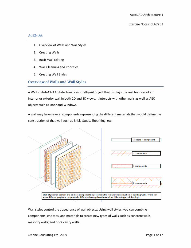
A wall may have several components representing the different materials that would define the
construction of that wall such as Brick, Studs, Sheathing, etc.
Wall styles control the appearance of wall objects. Using wall styles, you can combine
components, endcaps, and materials to create new types of walls such as concrete walls,
masonry walls, and brick cavity walls.

AutoCAD Architecture 1
Exercise Notes: CLASS 03
©Xone Consulting Ltd. 2009 Page 2 of 17
The display of a wall object depends on the direction from which you view the wall. In a plan
view, the wall object is displayed as parallel lines, as an architect would typically draw a wall. In
3D view, the wall object is displayed, as it would appear in the real world, with surfaces showing
length, thickness, and height. You control what you want to display in each particular view by
working with the Display System.
Creating Walls
Walls may be created by selecting a Wall tool from the Tool Palette or the Build panel on the
Ribbon and then picking points in your drawing to specify the endpoints of each wall segment.
As you pick points you will see your cursor and tracking lines appear along the Justification line
for the wall. Press the CTRL key while drawing a wall to Flip it or reverse the components.
The justification for a wall can be set to Left, Right, Center, and Baseline from within the
Properties Palette. While drawing the wall, you can also press the SHIFT key to cycle through the
available justifications. The Baseline justification may be placed at some point within the extents
of the wall. This is useful for drawing walls along their main structure as for a foundation wall
with an attached footing extending beyond the width of the main wall.
By selecting the Arc option of the wall command you can create curved walls defined by 3 points
on the arc. To create a curved wall with a specified radius, draw an arc along the desired
baseline, and then convert the arc to a wall by selecting it, right clicking on a wall tool and
choosing Apply to / Linework from the context flyout. Curved walls can also be created by using
the AutoCAD Fillet command and selecting two adjacent walls.

AutoCAD Architecture 1
Exercise Notes: CLASS 03
©Xone Consulting Ltd. 2009 Page 3 of 17
The default multi-component walls defined in the existing ACA wall styles have been created in
such a fashion that specifying points in a clockwise direction, will ensure that exterior
components will be drawn to the outside of the building. If you wish to draw the walls in a
counterclockwise direction, press the CTRL key when you start drawing the wall segments and it
will Flip the wall construction, reversing the component layout.
To check the wall direction for walls, look for an arrow-shaped grip that will always appear on
the exterior side of a selected wall. It you pick this grip; you can reverse the wall and change its
direction. When Reversing a wall with the flip grip, by default it will maintain the dimensions and
location of the wall. If you press CTRL while picking the Flip grip, the justification line will be
maintained at its current location and it will change the location of the wall. (unless the Baseline
is also at the Center of the wall).
AutoCAD Architecture 1
Exercise Notes: CLASS 03
©Xone Consulting Ltd. 2009 Page 4 of 17
Walls will automatically clean up with other walls if they belong to the same cleanup group and
are at the same elevation.
Single component walls may be created from Mass Elements in any 3D shape. Multi component
walls can be modified in variety of ways including Plan modifiers, Body Modifiers, Sweeps,
Interference Conditions, and Roof Line / Floor Line editing.
When you add a door or window to a Wall, it will automatically add a hole to that wall. If you
move the door or window, the hole will move with it and if you delete the door or window, the
hole in the wall will be deleted. When the wall is moved, the objects within the wall are moved
as well and if you delete the wall, all objects contained within it will be deleted as well.
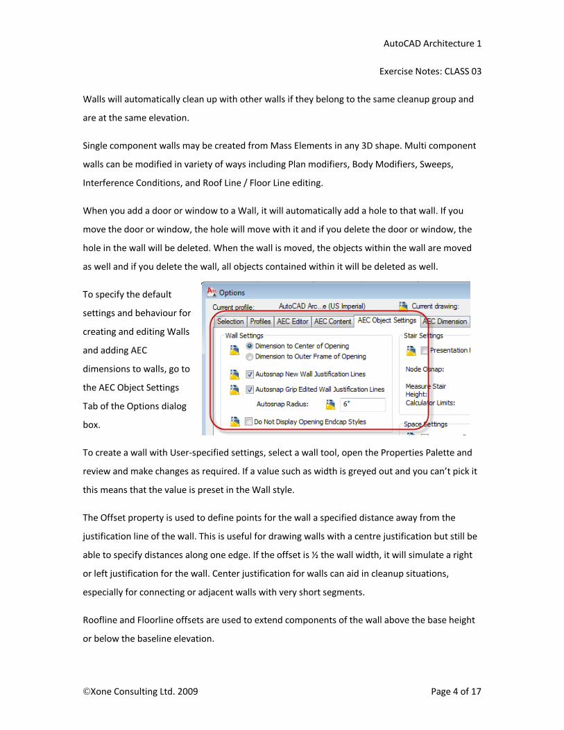
To specify the default
settings and behaviour for
creating and editing Walls
and adding AEC
dimensions to walls, go to
the AEC Object Settings
Tab of the Options dialog
box.
To create a wall with User-specified settings, select a wall tool, open the Properties Palette and
review and make changes as required. If a value such as width is greyed out and you can’t pick it
this means that the value is preset in the Wall style.
The Offset property is used to define points for the wall a specified distance away from the
justification line of the wall. This is useful for drawing walls with a centre justification but still be
able to specify distances along one edge. If the offset is ½ the wall width, it will simulate a right
or left justification for the wall. Center justification for walls can aid in cleanup situations,
especially for connecting or adjacent walls with very short segments.
Roofline and Floorline offsets are used to extend components of the wall above the base height
or below the baseline elevation.
AutoCAD Architecture 1
Exercise Notes: CLASS 03
©Xone Consulting Ltd. 2009 Page 5 of 17
Basic Wall Editing
Walls can be edited a number of ways after they have been added. You can edit many of the
properties of a wall including its dimensions, its shape, and even its style from the Properties
Palette. If any values are greyed out in the Properties palette they are defined in the wall style.
Under General, straight wall segments may be converted to arc walls.
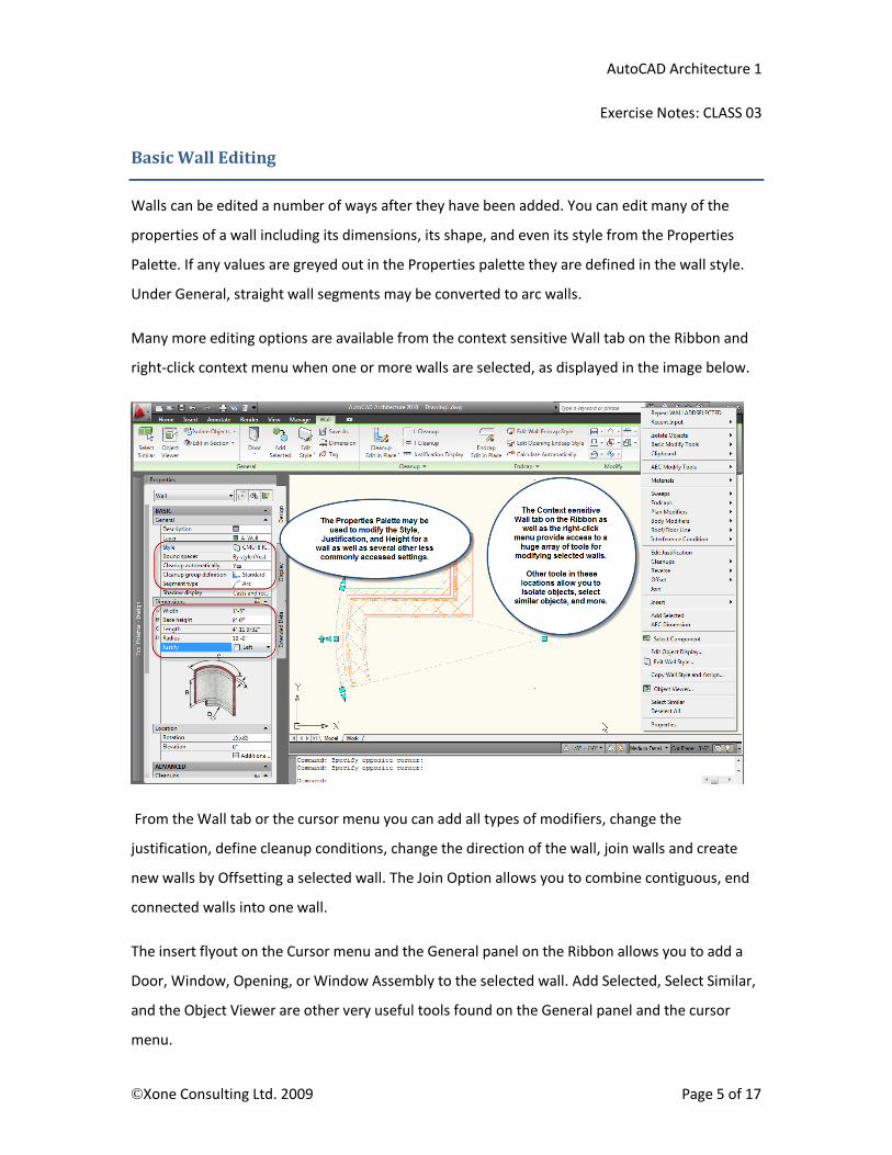
Many more editing options are available from the context sensitive Wall tab on the Ribbon and
right-click context menu when one or more walls are selected, as displayed in the image below.
From the Wall tab or the cursor menu you can add all types of modifiers, change the
justification, define cleanup conditions, change the direction of the wall, join walls and create
new walls by Offsetting a selected wall. The Join Option allows you to combine contiguous, end
connected walls into one wall.
The insert flyout on the Cursor menu and the General panel on the Ribbon allows you to add a
Door, Window, Opening, or Window Assembly to the selected wall. Add Selected, Select Similar,
and the Object Viewer are other very useful tools found on the General panel and the cursor
menu.
AutoCAD Architecture 1
Exercise Notes: CLASS 03
©Xone Consulting Ltd. 2009 Page 6 of 17
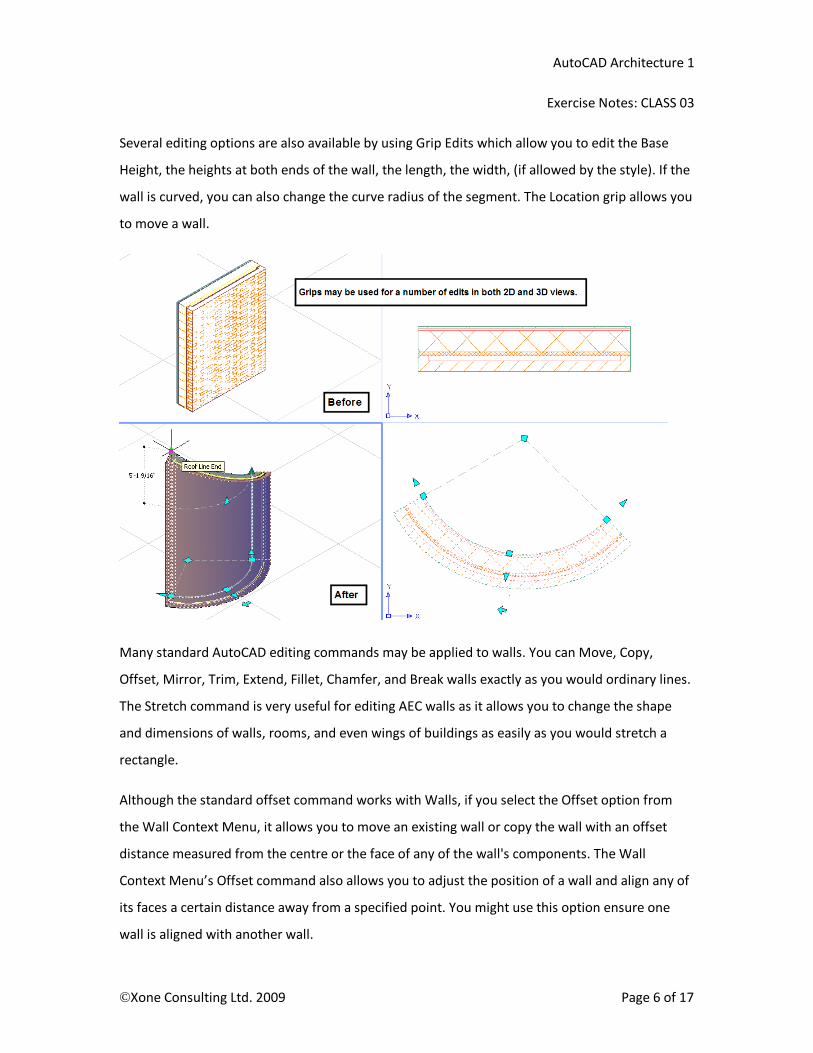
Several editing options are also available by using Grip Edits which allow you to edit the Base
Height, the heights at both ends of the wall, the length, the width, (if allowed by the style). If the
wall is curved, you can also change the curve radius of the segment. The Location grip allows you
to move a wall.
Many standard AutoCAD editing commands may be applied to walls. You can Move, Copy,
Offset, Mirror, Trim, Extend, Fillet, Chamfer, and Break walls exactly as you would ordinary lines.
The Stretch command is very useful for editing AEC walls as it allows you to change the shape
and dimensions of walls, rooms, and even wings of buildings as easily as you would stretch a
rectangle.
Although the standard offset command works with Walls, if you select the Offset option from
the Wall Context Menu, it allows you to move an existing wall or copy the wall with an offset
distance measured from the centre or the face of any of the wall's components. The Wall
Context Menu’s Offset command also allows you to adjust the position of a wall and align any of
its faces a certain distance away from a specified point. You might use this option ensure one
wall is aligned with another wall.
AutoCAD Architecture 1
Exercise Notes: CLASS 03
©Xone Consulting Ltd. 2009 Page 7 of 17
Wall Cleanups and Priorities
You can control how walls clean up with each other when they meet or cross through Cleanup
Groups, Cleanup Circles, Graphlines, and component priorities
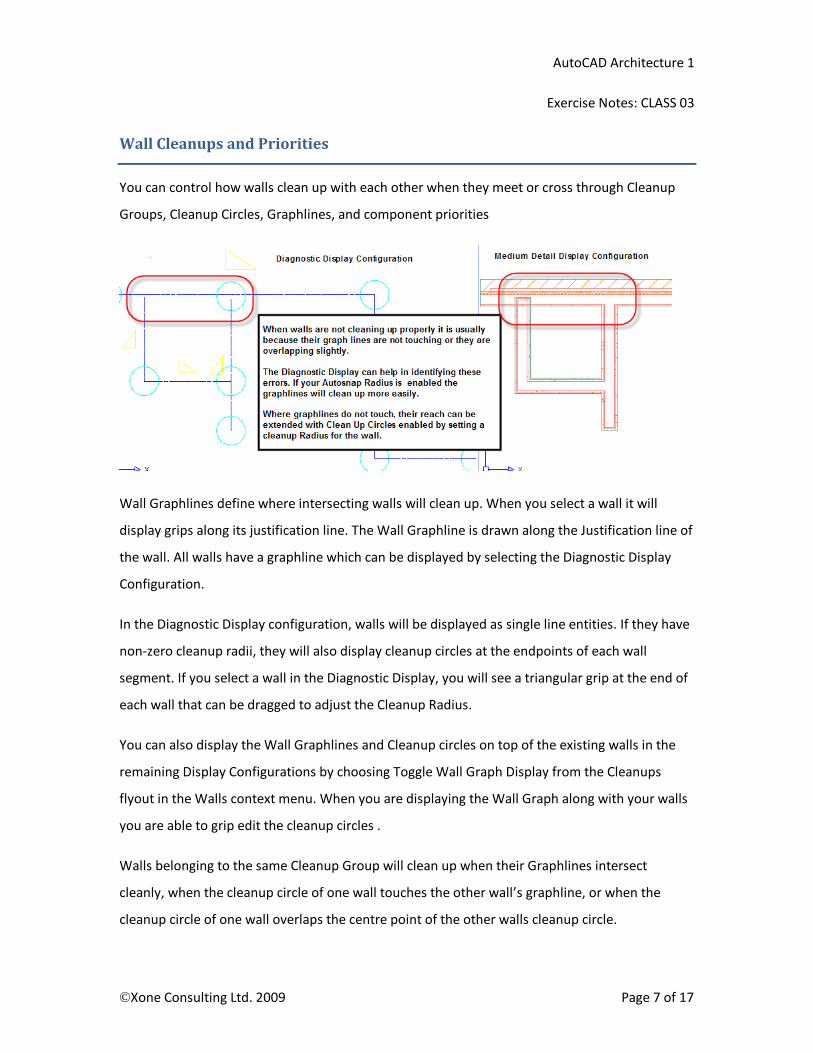
Wall Graphlines define where intersecting walls will clean up. When you select a wall it will
display grips along its justification line. The Wall Graphline is drawn along the Justification line of
the wall. All walls have a graphline which can be displayed by selecting the Diagnostic Display
Configuration.
In the Diagnostic Display configuration, walls will be displayed as single line entities. If they have
non-zero cleanup radii, they will also display cleanup circles at the endpoints of each wall
segment. If you select a wall in the Diagnostic Display, you will see a triangular grip at the end of
each wall that can be dragged to adjust the Cleanup Radius.
You can also display the Wall Graphlines and Cleanup circles on top of the existing walls in the
remaining Display Configurations by choosing Toggle Wall Graph Display from the Cleanups
flyout in the Walls context menu. When you are displaying the Wall Graph along with your walls
you are able to grip edit the cleanup circles .
Walls belonging to the same Cleanup Group will clean up when their Graphlines intersect
cleanly, when the cleanup circle of one wall touches the other wall’s graphline, or when the
cleanup circle of one wall overlaps the centre point of the other walls cleanup circle.
AutoCAD Architecture 1
Exercise Notes: CLASS 03
©Xone Consulting Ltd. 2009 Page 8 of 17
To keep walls from cleaning up, you can set the "Cleanup Automatically" property to No for one
of the selected walls. A second option is to create a new cleanup group in the style manager and
assign it to one of the sets of walls with the Properties Palette.
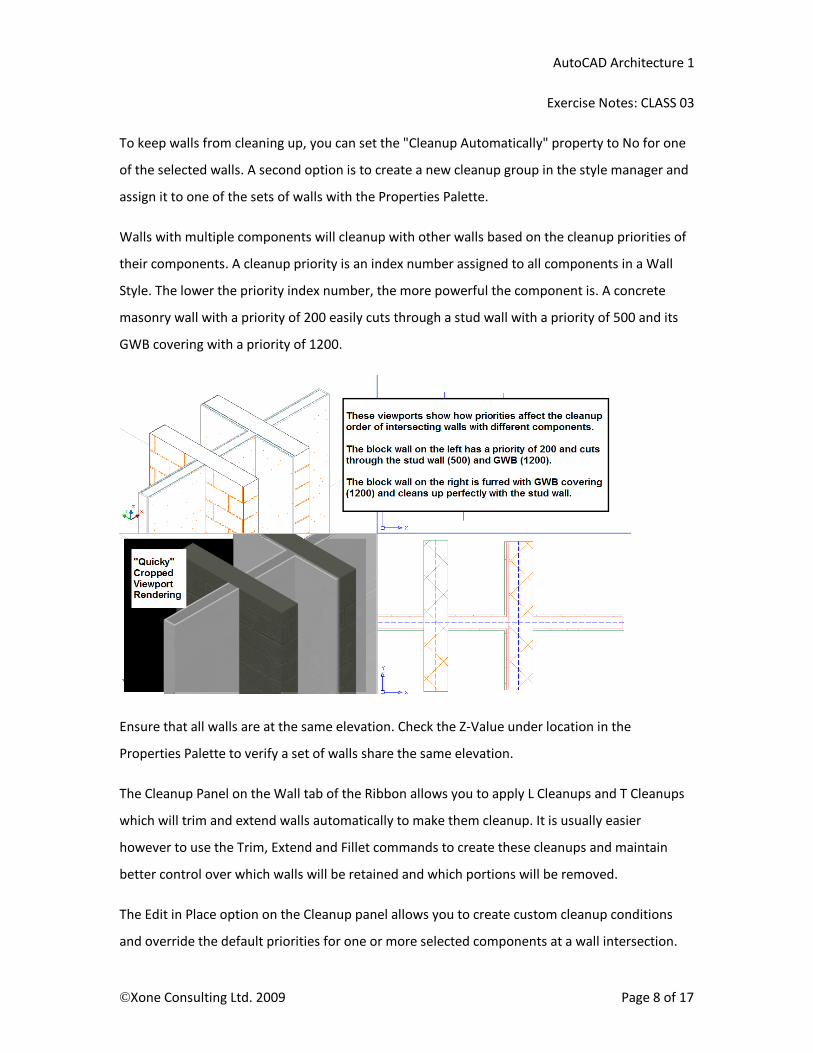
Walls with multiple components will cleanup with other walls based on the cleanup priorities of
their components. A cleanup priority is an index number assigned to all components in a Wall
Style. The lower the priority index number, the more powerful the component is. A concrete
masonry wall with a priority of 200 easily cuts through a stud wall with a priority of 500 and its
GWB covering with a priority of 1200.
Ensure that all walls are at the same elevation. Check the Z-Value under location in the
Properties Palette to verify a set of walls share the same elevation.
The Cleanup Panel on the Wall tab of the Ribbon allows you to apply L Cleanups and T Cleanups
which will trim and extend walls automatically to make them cleanup. It is usually easier
however to use the Trim, Extend and Fillet commands to create these cleanups and maintain
better control over which walls will be retained and which portions will be removed.
The Edit in Place option on the Cleanup panel allows you to create custom cleanup conditions
and override the default priorities for one or more selected components at a wall intersection.
AutoCAD Architecture 1
Exercise Notes: CLASS 03
©Xone Consulting Ltd. 2009 Page 9 of 17
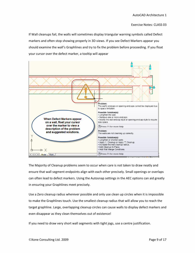
If Wall cleanups fail, the walls will sometimes display triangular warning symbols called Defect
markers and often stop showing properly in 3D views. If you see Defect Markers appear you
should examine the wall’s Graphlines and try to fix the problem before proceeding. If you float
your cursor over the defect marker, a tooltip will appear
The Majority of Cleanup problems seem to occur when care is not taken to draw neatly and
ensure that wall segment endpoints align with each other precisely. Small openings or overlaps
can often lead to defect markers. Using the Autosnap settings in the AEC options can aid greatly
in ensuring your Graphlines meet precisely.
Use a Zero cleanup radius wherever possible and only use clean up circles when it is impossible
to make the Graphlines touch. Use the smallest cleanup radius that will allow you to reach the
target graphline. Large, overlapping cleanup circles can cause walls to display defect markers and
even disappear as they clean themselves out of existence!
If you need to draw very short wall segments with tight jogs, use a centre justification.
AutoCAD Architecture 1
Exercise Notes: CLASS 03
©Xone Consulting Ltd. 2009 Page 10 of 17
Creating Wall Styles
Wall styles may be created from scratch in the Style Manager or you can create a wall style by
copying an existing style, assigning a new name to the copied style and then modifying the
properties as required.
The Wall components and their properties define the main structure of the wall. Each
component corresponds to a defining section of the wall such as brick, insulation, and frame
backup walls. Spaces such as air gaps must be included as well as placeholder components for
elements that may be swept along the wall such as a baseboard.
Wall components are rectangular volumes with their dimensions in section defined by a width, a
horizontal offset from a baseline, and vertical offsets from the Wall bottom, Wall top, Wall Base
Height, or Wall Baseline.
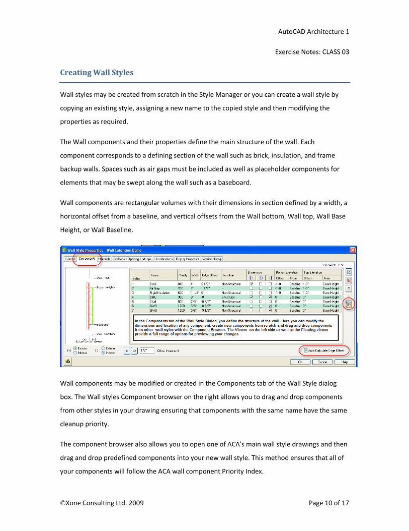
Wall components may be modified or created in the Components tab of the Wall Style dialog
box. The Wall styles Component browser on the right allows you to drag and drop components
from other styles in your drawing ensuring that components with the same name have the same
cleanup priority.
The component browser also allows you to open one of ACA's main wall style drawings and then
drag and drop predefined components into your new wall style. This method ensures that all of
your components will follow the ACA wall component Priority Index.

AutoCAD Architecture 1
Exercise Notes: CLASS 03
©Xone Consulting Ltd. 2009 Page 11 of 17
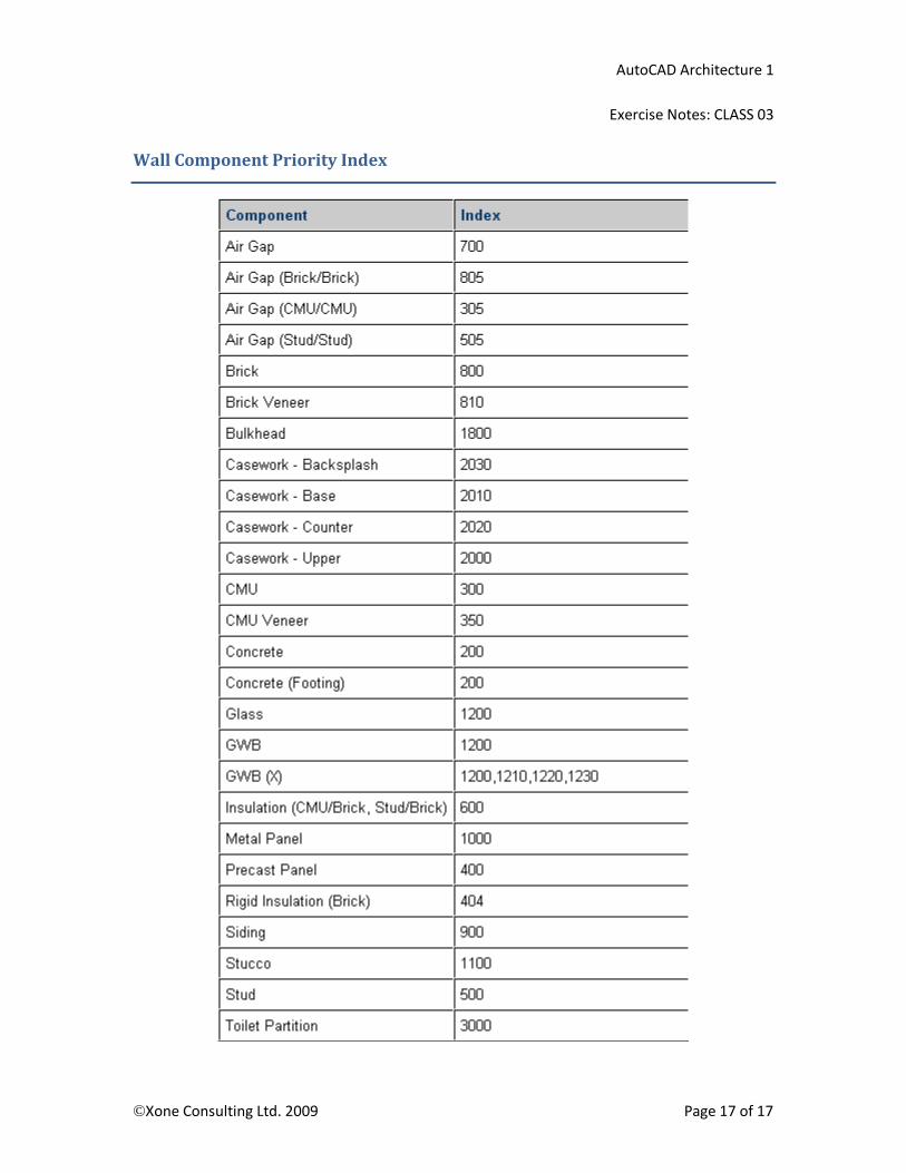
If you create components from scratch make sure you are setting the priority values to
accommodate cleanups with other walls. Refer to the component priority index shown on the
last page of the notes for this lesson or in the help file to make your custom components follow
the priorities in the ACA Priority index.
Components are defined with a width and edge offset from an imaginary vertical plane running
through the wall at a user defined location. Edge offsets may be defined with positive values (to
the exterior) and negative values (to the interior) but the widths are always set with positive
values.
Some complex wall types will include components that do not correspond to the Height of the
wall. An Exterior Brick Veneer wall on the first floor of a multi-storey house would be defined
with a height measuring from the first floor to the ceiling height. This would be the height of the
frame backup wall that will extend between these levels. On the outside of the wall however, the
exterior sheathing, air space and brick will all extend down over the outside of the floor
structure. These components could also be set to extend up in front of the next floor system.
AutoCAD Architecture 1
Exercise Notes: CLASS 03
©Xone Consulting Ltd. 2009 Page 12 of 17
When creating components which will vary in height from other components in the style, the
elevations may be defined relative to either the top and bottom of the entire wall, or to the
baseline and base height defined by the structural frame wall. Offset distances may be set with
either positive or negative values. Positive values follow the Positive Z direction and negative
values follow the Negative Z direction.
All of the default ACA wall styles are defined with component top elevations set to 0" offset from
the Wall Top and component bottom elevations set tot 0" offset from the Wall Bottom.
When you add custom components, you can define their function as being structural or non-
structural. Later, when adding AEC dimensions to a wall, you can optionally dimension only the
structural components.
The Dimensions settings further allow you to fine-tune how dimensions will be added when you
dimension the wall. Every component can be set to be dimensioned to the left side, right side, or
its centre.
The Display Properties tab in the Wall Style Editor allows you to override the drawing default
properties such as lineweight, visibility, linetype, and hatch pattern setting s for any component.
If a component's display properties is set to "by Material", it passes control of the display
properties over to the Material assignment for that component.
The Materials tab in the Wall Style Editor provides access to Material assignments for your wall
components. Materials offer more control over the display of components than available
through the regular Display properties. Not only are lineweights, colors, and section hatch
patterns available, but you can additionally specify surface hatching patterns and even render
texture settings for elevation and perspective views. Materials will be covered in more detail in
lesson 5 of this course.
The Endcaps and Opening Endcaps tab allows you to assign different wrapping conditions at wall
ends and openings such as at doors and windows. Endcaps will be covered in more detail in
lesson 4 of this course.

AutoCAD Architecture 1
Exercise Notes: CLASS 03
©Xone Consulting Ltd. 2009 Page 13 of 17
Exercise Notes – Importing and Changing Wall Styles
1. Open the floor plan you created in class 01. Switch to the ACA1 – Plot Plan layout.
2. From the Manage tab on the Ribbon, open the Style Manager and select the Architectural
Objects folder below your drawing name in the left pane. Browse to Wall Styles and see what
you have. If you have already been experimenting you may have several styles that are not
being used. Pick the Purge Styles icon at the top and Purge your drawing of all unreferenced
styles. You must pick Apply and close the dialog to make the changes stay in effect.
3. Open the Content Browser (CTRL-4) and select the Design Tool Catalog Imperial. Open the
Walls category, go to Stud walls, and then browse until you find a style called Stud-X. An X in
a wall style name indicates that it has a variable width. Using the I-Drop icon, drag and drop
the style into your drawing and then hit escape when prompted to select a start point.
4. Select the interior walls with a width of 6 ½”, open the Properties palette and in the Style
pulldown, set the style to “Stud-X”. Leave the width at 6 ½”. Notice the walls no longer clean
up properly with the other interior walls or the exterior walls.
5. Select the remaining interior walls, and set their style to Stud-X as well. Now, all of the
interior walls should clean up with each other, but not the “standard” exterior walls.
Creating Wall Styles
1. Let's create a custom brick veneer wall style for the exterior walls. From the Manage tab on
the Ribbon, choose Style Manager and set the Style Manager to display the wall styles in the
current drawing. Choose the filter icon to filter the display of styles to only walls.
2. With the wall style type selected, right-click and choose New from the shortcut menu.
3. Type a name for the new wall style and press ENTER. (ACA1_Brick-3.5 Air-1 Ply-.5 Stud 6)
4. To edit the style properties of the new wall style, select the style in the right pane, right-click
and choose Edit. You can also double click the style name or just pick the new style in the left
pane under the list of wall styles to display its properties in the right pane.
AutoCAD Architecture 1
Exercise Notes: CLASS 03
©Xone Consulting Ltd. 2009 Page 14 of 17
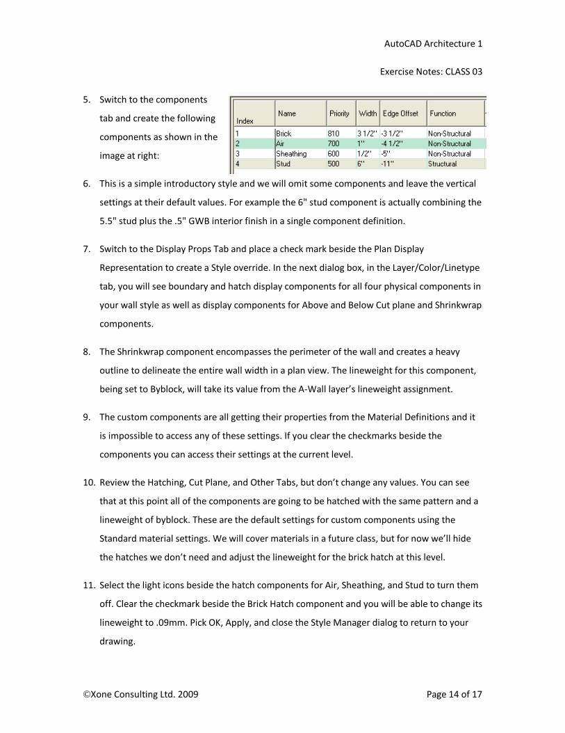
5. Switch to the components
tab and create the following
components as shown in the
image at right:
6. This is a simple introductory style and we will omit some components and leave the vertical
settings at their default values. For example the 6" stud component is actually combining the
5.5" stud plus the .5" GWB interior finish in a single component definition.
7. Switch to the Display Props Tab and place a check mark beside the Plan Display
Representation to create a Style override. In the next dialog box, in the Layer/Color/Linetype
tab, you will see boundary and hatch display components for all four physical components in
your wall style as well as display components for Above and Below Cut plane and Shrinkwrap
components.
8. The Shrinkwrap component encompasses the perimeter of the wall and creates a heavy
outline to delineate the entire wall width in a plan view. The lineweight for this component,
being set to Byblock, will take its value from the A-Wall layer’s lineweight assignment.
9. The custom components are all getting their properties from the Material Definitions and it
is impossible to access any of these settings. If you clear the checkmarks beside the
components you can access their settings at the current level.
10. Review the Hatching, Cut Plane, and Other Tabs, but don’t change any values. You can see
that at this point all of the components are going to be hatched with the same pattern and a
lineweight of byblock. These are the default settings for custom components using the
Standard material settings. We will cover materials in a future class, but for now we’ll hide
the hatches we don’t need and adjust the lineweight for the brick hatch at this level.
11. Select the light icons beside the hatch components for Air, Sheathing, and Stud to turn them
off. Clear the checkmark beside the Brick Hatch component and you will be able to change its
lineweight to .09mm. Pick OK, Apply, and close the Style Manager dialog to return to your
drawing.
AutoCAD Architecture 1
Exercise Notes: CLASS 03
©Xone Consulting Ltd. 2009 Page 15 of 17
12. Change the wall style for your exterior walls to the new Brick veneer style and Zoom in to a
corner of the wall to review the lineweight settings. Because we include the ½” sheathing
component as well as the 1” air space in our wall construction, there are too many lines and
not enough space to display them without the lines burning together.
13. Pick a wall, right-click and choose Edit Wall Style. Access the Display Properties Style override
and turn off the display of the boundaries for the Air Gap and Sheathing Components. The
wall will now display in a plan view as having a 1.5” space between the outside of the stud
component and the inside of the brick component. The cavity will be displayed by default
and will make the plan drawing read better. Pick Ok twice to exit the Wall Style dialog and
review the appearance of the wall again. The perimeter should be using a Shrinkwrap with a
.35mm line from the Layer setting. The interior components are .25mm from the material
setting and the brick hatch is using a .09 mm override from the Wall style display properties.
14. At 1/8" = 1'-0", the .25mm lineweight is still a bit heavy. Go back into the Display Properties
for the new style, clear the checkmarks beside the Brick and Stud components, and set their
lineweight to .18mm. Apply the changes and review the results. Better. :)
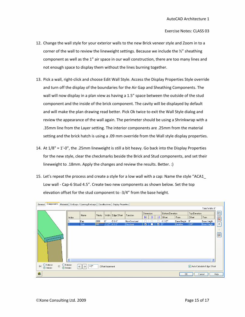
15. Let’s repeat the process and create a style for a low wall with a cap: Name the style “ACA1_
Low wall - Cap-6 Stud 4.5”. Create two new components as shown below. Set the top
elevation offset for the stud component to -3/4” from the base height.

AutoCAD Architecture 1
Exercise Notes: CLASS 03
©Xone Consulting Ltd. 2009 Page 16 of 17
16. There are two more steps to properly display the components for the low wall style. Switch
to the Display Properties tab, put a check mark under the Style override for the Plan Display
Representation.
17. In the display properties dialog box, select the other tab and put a check beside “Display
Inner Lines Below”.
18. In the Cut Plane tab, put a check mark beside "Override Display Configuration Cut plane" and
set the cut plane height to 41.5”. These last few steps ensure that the cut plane will pass
through the cap component and just above the stud component, allowing the stud portion
to be displayed as hidden lines.
19. Add the low wall as shown on the revised floor plan. The Height is 42”. Hmmm...no hidden
lines are displaying yet and the lineweight is a bit heavy for a low wall.
20. Select the wall, right click and choose Edit wall style. Access the Display properties for the
wall. Turn on the "Below Cut Plane" component which we disabled at the Drawing default
level in the previous class. Set the linetype to Hidden2, the lineweight to .15mm, and the
linetype scale override to 0.5. Pick Ok and close the dialog to see the results. The lineweights
are too heavy and you cannot distinguish the hidden lines next to the visible lines.
21. Edit the wall style again and in the Display properties controls, turn off the Shrinkwrap
component visibility, clear the checkmark for By Material beside the Cap component and
reduce the lineweight for this component to .18mm. Pick Ok and exit the wall style dialog to
review the results. By turning off the Shrinkwrap and reducing the lineweight the hidden
lines should now be distinct from the adjacent visible lines.
22. The low wall will show a slight error at the open end where the cap is not extending past the
stud component. This situation can be resolved with a custom endcap, which we shall design
in the next class. For now, save and close your file.
AutoCAD Architecture 1
Exercise Notes: CLASS 03
©Xone Consulting Ltd. 2009 Page 17 of 17
Wall Component Priority Index


![GABION WALLS DESIGNgabions.net/downloads/Documents/MGS_Design_Guide.pdf · Mechanically Stabilized Earth (MSE) Gabion Wall [Reinforced Soil Wall] GABION WALLS DESIGN Gabion Gravity](https://img.dokumen.tips/doc/110x75/5a79b6847f8b9a9e0c8c102b/gabion-walls-stabilized-earth-mse-gabion-wall-reinforced-soil-wall-gabion-walls.jpg)