Embed Size (px)
Citation preview
Overview of the Space Power Conversion
and Energy Storage Technologies
Subbarao Surampudi,
NASA-Jet Propulsion Laboratory Pasadena, CA 91109
January 24, 2011

Outline
• Overview of Potential Future Missions
• Power Technology Challenges
• Radioisotope Power Source Technology
• Solar Cell and Array Technology
• Energy Storage Technology
• Summary

Power Technology Challenges

Space Power Technology Area Overview
• Power system is 20-30% of spacecraft mass and costs 20% of the spacecraft budget.
• The major power subsystems are:
– Power Generation/Conversion
– Energy Storage
– Power Management and Distribution
• Space missions need a variety of power solutions
– Solar power systems
– Nuclear power systems
– Batteries
– Fuel Cells
– New Technology
4

Operational Envelope of Power Conversion
Technologies 10 5 The image cannot be displayed. Your computer may not have enough memory to open the image, or the image may have been corrupted. Restart your computer, and then open the file again. If the red x still
appears, you may have to delete the image and then insert it again.
The image cannot be displayed. Your computer may not have enough memory to open the image, or the image may have been corrupted. Restart your computer, and then open the file again. If the red x still appears, you may have to delete the image and then insert it again.
The image cannot be displayed. Your computer may not have enough memory to open the image, or the image may have been corrupted. Restart your computer, and then open the file again. If the red x still appears, you may have to delete the image and then insert it again.
The image cannot be displayed. Your computer may not have enough memory to open the image, or the image may have been corrupted. Restart your computer, and then open the file again. If the red x still appears, you may have to delete the image and then insert it again.
The image cannot be displayed. Your computer may not have enough memory to open the image, or the image may have been corrupted. Restart your computer, and then open the file again. If the red x still appears, you may have to delete the image and then insert it again.
The image cannot be displayed. Your computer may not have enough memory to open the image, or the image may have been corrupted. Restart your computer, and then open the file again. If the red x still appears, you may have to delete the image and then insert it again.
10 -1
10 0
10 1
10 2
10 3
10 4
Ele
ctr
ic P
ow
er
Level
(kW
e)
1 hour 1 day 1 month 1 year 10 years
Chemical
Fission Reactors
• Fission Reactors • Solar
• Dynamic Radioisotope Generators
• Solar
Solar • Static Radioisotope Generators
• Solar
Duration of Use Space missions need a variety of power solutions ( solar
cells, radioisotope power sources, nuclear reactor, batteries )

Performance Envelope of Electrochemical
Power Sources
Service life dictates the choice of energy storage technology
0.1
Mis
sile
Batteries
High Temperature & Advanced Batteries
Secondary Batteries
Primary Batteries
Other Reserve
Batteries
Fuel Cell Systems
1 10 100 1000 10,000
Po
we
r, W
Hours of discharge
Capacitors

1373 W/m2
610 W/m2
50 W/m2
1 W/m2
2 W/m2
4 W/m2
15 W/m2
2200 W/m2
~10 AU
~20 AU
~30 AU
~6 AU
~1 AU
reference
~40 AU
<1 AU
Pluto
Neptune
Uranus
Saturn
Jupiter
Mars
Earth
Venus
• Flight times are long
• Need power systems with >10 years life
• Mass is at an absolute premium
• Need power systems with high specific power and scalability
• Some missions require ion propulsion
to reduce flight time
• Need high power capabilities with
high sp. power and low cost
• Over 3 orders of magnitude reduction in solar irradiance
from Earth to Pluto
• Highly efficient solar cells/nuclear power systems
Major Power Challenges of Solar System
Missions

Extreme Environments in Planetary Missions
0,0
Temperature oC
0.01
0.1
1.0
10
100
100 -5
0 -100 -150 -200 -250 200 300 400
Limit of Military
Interest
Rad
iati
on
Dose
in
MR
ad
s
Limit of Military
Interest
Pluto
Venus
Mercury
Io-Volcano
Mars
Europa
Titan Triton
Earth
Io
Major Challenges of Solar System Missions
• Some missions require high radiation
resistant power systems
• Outer planetary surface missions require
low temperature power systems
Inner planetary missions require
power systems that can operate in very
high temperature environments
• Some outer planetary missions require power
systems that can operate in deep space and in
dense or tenuous atmospheres
NASA Interest NASA Interest

SOP Technology Capabilities
Radioisotope Power Sources
Solar Cells
Rechargeable Batteries
Power System
Power Electronics
Technology Element Capability
30-100 Wh/kg >30,000 Cycles (30% DOD)
>10 years -10 to 30 C
Ni-H2
Rigid Panel 30-40 W/kg Flexible Fold Out Array : 40-60 W/kg
4-5 W/kg 6.5 % eff
GPHS RTG
Si cells 9-15% eff , TJ Cells 24-26%
22- 120 V dc
-55 to 75C, up to a 1Mrad
> 85% converter efficiency
0.5 to 20 kW,
28- 120 V dc
Direct Energy Transfer
Shunt Regulator/Radiator

Power System Technology Challenges
10
• Power systems that provide significant mass and volume savings ( 3-4 x SOP )
– High specific power solar arrays ( 500 W/kg, 2kg/kW)
– High specific mass nuclear power systems ( >5 kg/kW)
– High specific energy batteries (500 Wh/kg)
– High specific power fuel cells ( 400 W/kg)
• Power systems with high voltage (100-1000 V) high power (100 kW- 5 MW) capabilities.
– High Voltage & High Power Solar Arrays (1000 V; >100 kW)
– Nuclear fission (2 kWe; 40 kWe; > 1 MWe Power Systems)
– Aneutronic fusion power system ( >50 MW)
– High Voltage & High Power PMAD (100-1000 V; 10 kW-1 MW)
• Power systems with operational capability in extreme space environments
– Extreme Temperatures ( -100 to 450oC)
– High radiation environments (5 MRAD)
– Dusty environments
• Power systems with long life capability ( > 30 years), high reliability and safety
Radioisotope Power Systems

Why Radioisotope Power Systems?
• Provide power for deep space
missions where there is little or no
available solar energy
• Provide power for long duration
surface and subsurface exploration
missions where solar power not readily
or continuously available (lunar polar
craters, high Martian latitudes)
• Provide power for planetary nuclear
electric propulsion systems to remove
dependency on gravity assists
4
13
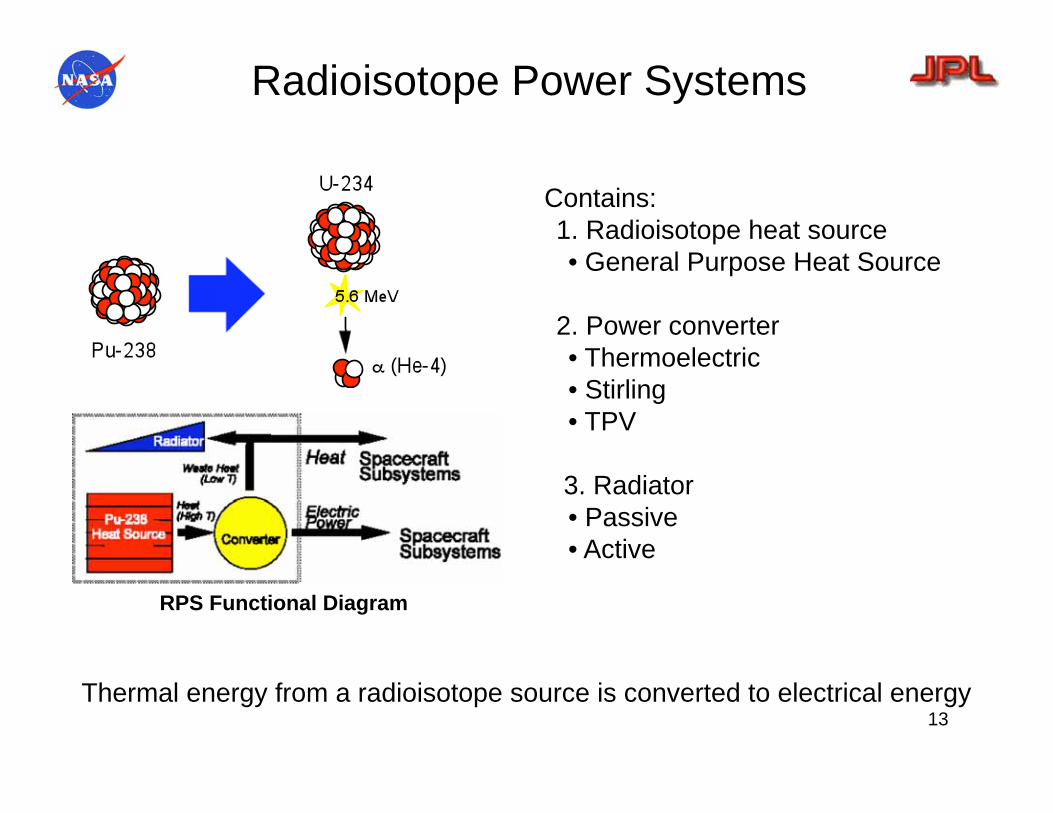
Radioisotope Power Systems
Contains:
1. Radioisotope heat source
• General Purpose Heat Source
2. Power converter
• Thermoelectric
• Stirling
• TPV
3. Radiator
• Passive
• Active
RPS Functional Diagram
Thermal energy from a radioisotope source is converted to electrical energy

14
Past NASA RTG Powered Missions
Apollo Voyager
Galileo Ulysses Cassini
Viking
Since 1961, 46 RTGs have been used on 26 US space systems.

• RTG’s were used safely in 28 missions since 1961
– 10 Earth orbit (Transit, Nimbus, LES)
– 8 planetary (Pioneer, Voyager, Galileo, Ulysses, Cassini, New Horizons)
– 6 on lunar surface (Apollo ALSEP)
– 4 on Mars surface (Viking 1& 2)
• 3 RHUs on Mars Pathfinder, 8 RHUs for each MER
5 May 22, 2007

Radioisotope Thermoelectric Generators
Used In Space Missions
285 We (BOM)
6.8% efficiency
5.1 We/kg
114 cm (44.9 in) long
42.7cm (16.8in) dia
56 kg (123 lb)
SiGe Thermoelectrics
Galileo, Ulysses, Cassini
& New Horizons
158 We (BOM)
6.6 % efficiency
4.2 We/kg
58.4 cm (23 in) long
39.7 cm (15.64 in) dia
38 kg (83.7lb)
SiGe Thermoelectrics
LES 8/9, Voyager 1/2
40.3 Watts (BOM)
6.2 % efficiency
3 We/kg
22.86 cm (9.0 in) long
50.8 cm (20 in) dia
~13 kg (28.6 lb)
PbTe Thermoelectrics
Nimbus B-1/III, Pioneer 10/11,
Viking 1/2
SiGe GPHS RTG
(1980-2006)
SiGe MHW RTG
(1970’s)
SNAP-19(PbTe RTG)
(1960-70’s)
Limitations: Low Specific Power & Low Efficiency

100 We Class RPS Under Development
• Multi-Mission RTG (MMRTG)
– Specfic Power: 2.8 We/kg
– System efficiency: 6.3%
– Design Life: 14 Years + Storage
– Power BOM/14 years: 125 We/100 We
– Environments: Deep space, Planetary
– Under development to support 2009 first launch
• Stirling Radioisotope Generator (SRG)
– Specific Power: ~ 6 We/kg
– System efficiency: 30%
– Design Life: 14 Years + Storage
– Power BOM: 130 We
– Environments: Deep space, Planetary
– Under development to support 2015 first launch
- Ulysses, Gallileo, Cassini, New Horizons
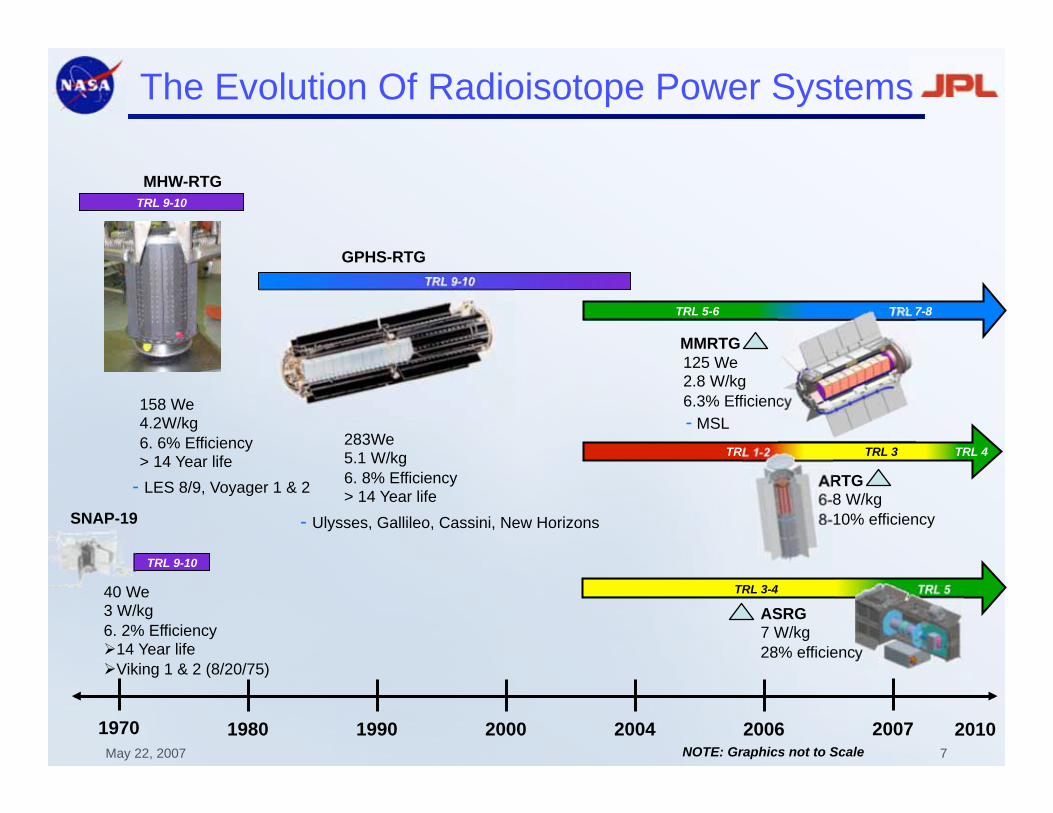
TRL 7-8 TRL 5-6
MHW-RTG
TRL 9-10
GPHS-RTG
The Evolution Of Radioisotope Power Systems
1970 1980 1990 2000 2004 2006 2007 NOTE: Graphics not to Scale
- LES 8/9, Voyager 1 & 2
TRL 9-10
SNAP-19
TRL 9-10
MMRTG
TRL 4 TRL 1-2 TRL 3
ARTG 6-8 W/kg
8-10% efficiency
125 We 2.8 W/kg
6.3% Efficiency - MSL
ASRG 7 W/kg
28% efficiency
TRL 5 TRL 3-4
283We 5.1 W/kg
6. 8% Efficiency > 14 Year life
158 We 4.2W/kg
6. 6% Efficiency > 14 Year life
40 We 3 W/kg
6. 2% Efficiency 14 Year life
Viking 1 & 2 (8/20/75)
7 May 22, 2007
2010

Summary of Future Space Science Mission
Needs For Radioisotope Power Systems
• Need 100-300 Watt Class RTG Modules
– Future missions are smaller in size and require lower power
• Low Mass
– High Specific Power 8-10 W/kg (2 X SOA SiGe RTGs)
• High Efficiency 13-35 % (2-4 X SOA SiGe RTG’s)
– Uses Less Radioisotope Material
• Long Life
– 14 Years - Enable Deep Space Missions
• Low EMI & Vibration
– Enable use of High Precision Cameras
and Magnetometers
• Function in CO2 and other planetary Atmospheres
– Enable Long Duration Mars and other planetary surface
missions (> 2 earth years)
Titan
Organics
Explorer Mars Science
Laboratory
Europa Explorer

RPS Performance Ranges
0 5 10 15 20 25 30 35 40 2
3
4
5
6
7
8
9
10
11
12 S
pecif
ic P
ow
er
(We/k
g)
System Efficiency (%)
GPHS-RTG
MMRTG
Advanced Thermoelectric Generator
Reduced fuel consumption
Mass savings
Advanced Stirling Generator-650 C
Advanced Concepts
19 May 22, 2007

Advanced RTG
• Power: 250 We
• Specific Power: 6-8 W/kg
• Efficiency : 10%
• Employs advanced TE materials and
Unicouple configuration
– High ZT( >1.0) thermoelectric
materials
• Higher efficiency
– Segmented couples
• Each segment optimized for maximum
performance

Technical Approach to Achieve
High Efficiency and Long Life
• High ZT( >1.0) thermoelectric materials
– higher efficiency
• Segmented couples
– each segment optimized for maximum performance
• Large Delta T: (1275 to 525 K Operation)
– Higher efficiency
• Sublimation Control
– Aerogel
– Metal/metal oxide coatings

Further Advances in Stirling Engine Technology
Feasible by Increasing Hot End Temperature
Lenticular Honeycomb
Involute
Foil
High Efficiency Regenerator
850oC
Heater Head Temperature
ASRG
650oC Heater
Head Temperature
4 engines with Mar M 247
heater head fabricated by
Sunpower – Pratt & Whitney
Rocketdyne Team
Ceramic Heater Head

Solar Cells/Arrays

Applications of Photovoltaic Power Systems
• Used on >99% of the
space missions launched
to date:
– Earth Orbital : GEO, LEO,MEO
– Planetary Orbital/fly byes
– Ion Propulsion Missions:DS-1
– Mars, Jupiter, Venus, Mercury,
– Plantary Surface: Mars, Moon
– Human Exploration: ISS
MGS
MGS
MER
Deep Space 1
ISS
Mars Path Finder
Hubble Space Telescope GEO

SOA Solar Cells & Arrays-Overview
• Solar Cells – High efficiency Silicon and Multi Junction Solar Cells are presently
being used in many space missions
• Solar Arrays – Body mounted, rigid panel and flexible deployable arrays
are currently being used in many spacecraft.
– These arrays are mostly suitable for low–medium power (0.5-5 kW) applications
Cell Type Efficiency
High Efficiency Si Cells 16 %
Multi Junction Solar Cells 26.5%
Array Type Specific Power (W/kg)
Rigid Panel Array 30-40 (3 J)
Flexible Fold Out Arrays 30-50 (Si)
Concentrator Arrays 30 -60
Flexible fold out Arrays 8-100 (3 J)
Si
Performance of SOP Solar Cells and Arrays is Inadequate for Future Code-S Missions
Concentrated Array

Solar Array Environments for Space Science
Missions
Military, Com, NASA Code Y
NASA Code S
• High solar
intensity
• High
temperature • Electrons,
protons,
• Atomic oxygen
• Charging effects
(fields/particles missions)
• Low-intensity
• Low temperatures
• Jupiter radiation belt
• Dust contamination
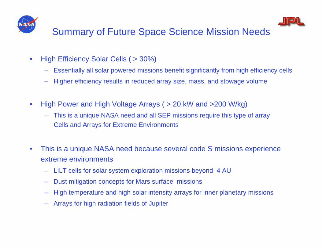
Summary of Future Space Science Mission Needs
• High Efficiency Solar Cells ( > 30%)
– Essentially all solar powered missions benefit significantly from high efficiency cells
– Higher efficiency results in reduced array size, mass, and stowage volume
• High Power and High Voltage Arrays ( > 20 kW and >200 W/kg)
– This is a unique NASA need and all SEP missions require this type of array
Cells and Arrays for Extreme Environments
• This is a unique NASA need because several code S missions experience
extreme environments
– LILT cells for solar system exploration missions beyond 4 AU
– Dust mitigation concepts for Mars surface missions
– High temperature and high solar intensity arrays for inner planetary missions
– Arrays for high radiation fields of Jupiter

Advanced Solar Cell Technologies
Under Development
Multi Junction Crystalline
Cell
Status:30% Goal: 39%
UltraFlex
Product Performance Targets:
•Specific Power*: 150-300 W/kg
•Stowage volume*: 30-70 kW/m3
•Status: 100 W/kg
The image cannot be displayed. Your computer may not have enough memory to open the image,
The image cannot be displayed. Your computer may not have enough
The image cannot be displayed. Your computer may not have enough memory to open the image,
Mars Solar Spectrum
Substrate
Thicker upper layer
Mars Solar Cells
Solar Array Dust Mitigation
Systems
Energy Storage Systems

Space Applications of Energy Storage Devices
• Energy storage devices are used in space
missions to:
– Provide primary electrical power to launch
vehicles,crew exploration vehicles, planetary
probes, astronaut equipment
– Store electrical energy in solar powered
orbital and Surface missions and provide
electrical energy during eclipse periods
– Meet peak power demands in nuclear
powered rovers, landers and planetary
orbiters
Space Station
Galileo
Europa Orbiter

SOP Energy Storage Technologies
Primary Batteries Rechargeable Batteries Fuel Cells
Li-SOCl2
Li-SO2
Ni-Cd
Ni-H2
Li-Ion
PEM
PEM
Alkaline
Ag-Zn Battery

Characteristics of SOP Primary Batteries
Limitations
• Moderate specific energy (100-250 Wh/kg)
• Limited operating temp range (-40 C to 70oC)
• Radiation tolerance poorly understood
• Voltage delay

Characteristics SOP Rechargeable Batteries
Limitations of Ni-Cd & Ni-H2 batteries:• Heavy and bulky• Limited operating temp range (-10oC to 30oC) • Radiation tolerance poorly understood.
Technology Mission Specific Energy, Wh/kg
Energy Density,
Wh/l
Operating Temp.
Range, o C
Design life,
Years
Cycle life Issues
Ag - Zn Pathfinder Lander
100 191 - 20 t0 25 2 100 Electrolyte Leakage
Limited Life
Ni - Cd Landsat, TOPEX
34 53 - 10 to 25 3 25 - 40K Heavy
Poor Low Temp. Perf.
Super Ni - Cd Sampex Battery, Image
28 - 33 70 - 10 to 30 5 58K Heavy
Poor Low Temp. Perf
IPV Ni - H 2 Space Station, HST, Landsat 7
8 - 24 10 - 10 to 30 6.5 >60K Heavy, Bulky Poor Low Temp. Perf
CPV Ni - H 2 Odyssey, Mars 98
MGS, EOS Terra
Stardust, MRO
30 - 35 20 - 40 - 5 to 10 10 to 14
50 K Heavy, Bulky Poor Low Temp. Perf
SPV Ni - H 2 Clementine, Iridium
53 - 54 70 - 78 - 10 to 30 10 <30 K Heavy Poor Low Temp. Perf
Li - Ion MER - Rover 90 250 -20 to 30 1 >500 Limited Life

Characteristics of Space Fuel cells
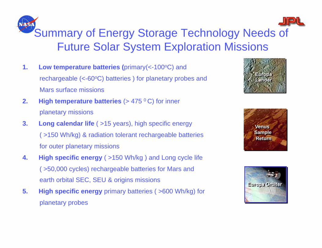
Summary of Energy Storage Technology Needs of
Future Solar System Exploration Missions
1. Low temperature batteries (primary(<-100oC) and
rechargeable (<-60oC) batteries ) for planetary probes and
Mars surface missions
2. High temperature batteries (> 475 0 C) for inner
planetary missions
3. Long calendar life ( >15 years), high specific energy
( >150 Wh/kg) & radiation tolerant rechargeable batteries
for outer planetary missions
4. High specific energy ( >150 Wh/kg ) and Long cycle life
( >50,000 cycles) rechargeable batteries for Mars and
earth orbital SEC, SEU & origins missions
5. High specific energy primary batteries ( >600 Wh/kg) for
planetary probes
Europa Orbiter
Europa Lander
Venus Sample
Return
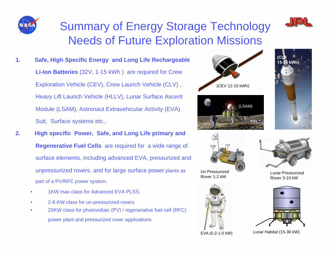
Summary of Energy Storage Technology
Needs of Future Exploration Missions
1. Safe, High Specific Energy and Long Life Rechargeable
Li-Ion Batteries (32V, 1-15 kWh ) are required for Crew
Exploration Vehicle (CEV), Crew Launch Vehicle (CLV) ,
Heavy Lift Launch Vehicle (HLLV), Lunar Surface Ascent
Module (LSAM), Astronaut Extravehicular Activity (EVA)
Suit, Surface systems etc.,
2. High specific Power, Safe, and Long Life primary and
Regenerative Fuel Cells are required for a wide range of
surface elements, including advanced EVA, pressurized and
unpressurized rovers, and for large surface power plants as
part of a PV/RFC power system.
• 1KW max class for Advanced EVA PLSS,
• 2-8 KW class for un-pressurized rovers
• 25KW class for photovoltaic (PV) / regenerative fuel cell (RFC)
power plant and pressurized rover applications.
(CEV 12-15 kWh)
(CLV
15-25 kWh)
(LSAM)
Lunar Habitat (15-30 kW) EVA (0.2-1.0 kW)
Un Pressurized
Rover 1-2 kW Lunar Pressurized
Rover 3-10 kW
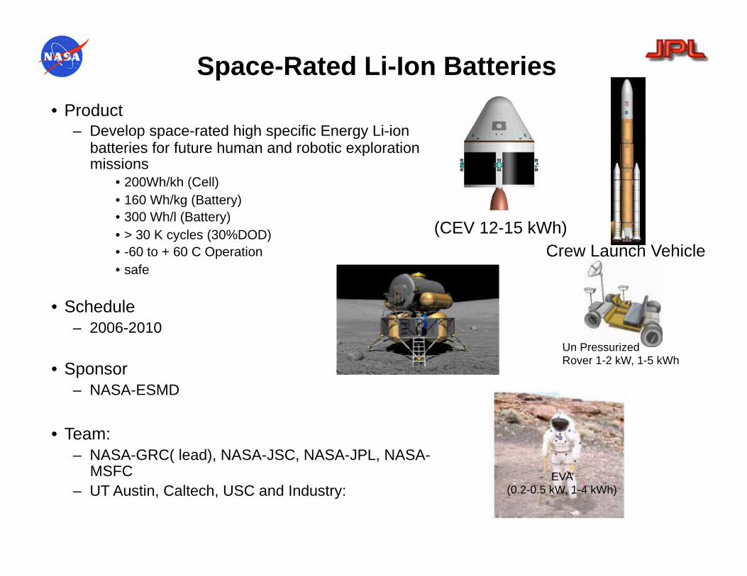
Space-Rated Li-Ion Batteries
• Product – Develop space-rated high specific Energy Li-ion
batteries for future human and robotic exploration missions
• 200Wh/kh (Cell)
• 160 Wh/kg (Battery)
• 300 Wh/l (Battery)
• > 30 K cycles (30%DOD)
• -60 to + 60 C Operation
• safe
• Schedule – 2006-2010
• Sponsor
– NASA-ESMD
• Team:
– NASA-GRC( lead), NASA-JSC, NASA-JPL, NASA-MSFC
– UT Austin, Caltech, USC and Industry:
(CEV 12-15 kWh)
Un Pressurized Rover 1-2 kW, 1-5 kWh
EVA (0.2-0.5 kW, 1-4 kWh)
Crew Launch Vehicle

PEM Fuel Cells
• Product
– Develop PEM primary and regenerative fuel cells
for future human lunar exploration missions
• 1-kW max class for advanced EVA portable life
support systems (primary fuel cell)
• 8-kW class for un-pressurized rovers (primary fuel
cell)
• 25-kW class for RFC surface power plants and
pressurized rovers (Regenerative Fuel Cell).
• Schedule
– 2006-2010
• Sponsor
– NASA-ESMD
• Team:
– NASA-GRC (lead), NASA-JSC, NASA-JPL,
– UT Austin, Caltech, USC and Industry: Lunar Habitat (15-30 kW, 5MWH)
Lunar Pressurized Rover 3-10 kW, 25-100kWh
EVA (0.2-0.5 kW, 1-4 kWh)
Un Pressurized Rover (1-2 kW, 1-5 kWh)

Summary and Conclusions

SOA Technology Capabilities
Radioisotope Power Sources
Solar Cells
Rechargeable Batteries
Power System
Power Electronics
Technology Element Capability
Ni-Cd
30-40 Wh/kg >30,000 Cycles (30% DOD)
>10 years -10 to 30 C
Ni-H2
Rigid Panel 30-40 W/kg Scarlet : 40-60 W/kg
4-5 W/kg 6.5 % eff
GPHS RTG
Si cells 9-15% eff , TJ Cells 24-26%
22- 120 V dc
-55 to 75C, up to a 1Mrad
> 85% converter efficiency
0.5 to 20 kW,
28- 120 V dc
Direct Energy Transfer
Shunt Regulator/Radiator

Space Power Technologies
Solar Cells
Radioisotope
Power Sources
Rechargeable
Batteries
Past Present Future
MHW RTG
4-5 W/kg 6.5 % eff
GPHS RTG
3-4 W/kg 6.5 % eff
35 Wh/kg >30,000
Cycles (30% DOD)
-10 to 30 C
35 Wh/kg >60,000 Cycles
(30% DOD) -10 to 30 C
Ni-Cd Ni-H2
Segmented TE
Stirling
5-10 W/kg 10-30- % eff
TJ Solar cells
Flexible Panel Array
Si Solar cells Rigid Panel Array
High eff. Cells
Low Mass Array 30-40 W/kg 9-15 % eff 100W/kg
25% eff
35% Eff
250 W/kg @ 35%
Li-Ion Batteries Li-Polymer Batteries
200 Wh/kg 50,000 Cycles
(30% DOD) -60to 60C Batteries
Summary and Conclusions
• Power conversion and energy storage systems have been used in robotic
and human space missions launched since 1960
– Launch vehicles: silver zinc batteries
– Robotic GEO, LEO spacecraft: solar arrays in combination with Ni-Cd, Ni-H2
– Robotic planetary missions: RTG’s, solar arrays, Ni-Cd/Ni-H2 batteries, Li
primary batteries
– Space shuttle: Alkaline Fuel Cells
• Future space missions have unique power conversion and energy storage
requirements
– Large power and energy storage capabilities
– Mass and volume efficiency (2-10 X vs SOP)
– Long life (> 15 years)
– Ability to operate in extreme environments
– Human rated safety and high reliability

Summary and Conclusions (continued)
• State of practice power conversion and energy storage systems have
limited performance capabilities and do not meet all future critical space
mission needs.
– Limited operating temperature range (-20o-60oc for rechargeable, -40o – 60oc)
– Radiation tolerance poorly understood
– Heavy and bulky
– Low power and energy capability
• Development of advanced power conversion and energy storage
technologies required to meet future space mission needs
– Radioisotope power systems: high specific power, high efficiency, long life,
– Solar cells/arrays: high efficiency solar cells, LILT cells, low mass and low
stowage volume arrays, high power arrays
– Batteries: high specific energy, long life, RAD hard, low temperature batteries,
human rated safety
– Fuel cells: medium power PEM fuel cells, regenerative fuel cells, small fuel
cells

For Planning and Discussion
Purposes Only
45
Acknowledgments
The work described here was carried
out at the Jet Propulsion Laboratory
(JPL), California Institute of
Technology, under contract with the
National Aeronautics and Space
Administration (NASA)