Embed Size (px)
Citation preview
NASA Technical Memorandum 88895
8
Overview of the 1986 Free-Piston Stirling Activities at NASA Lewis Research Center
(NASA-TM-88895) C V Z R I I E U CP ?BE 1986 N87- 166 € 3 F E E E - P I S I C N 3116LING A C T I V I T I E S A I NASA LEWIS btSEA3CET CENTER ( H A S A ) 17 @ CSCL Y3F
Unclas G3/85 43370
Donald L. Alger Lewis Research Center Cleveland, Ohio
Prepared for the Twenty -fourth Automotive Technology Development Contractors'
sponsored by the U.S. Department of Energy Dearborn, Michigan, October 27-30, 1986
? Coordination Meeting
https://ntrs.nasa.gov/search.jsp?R=19870007230 2018-06-12T02:42:00+00:00Z

OVERVIEW OF THE 1986 FREE-PISTON STIRLING ACTIVITIES
AT NASA LEWIS RESEARCH CENTER
ABS TRACT
Donald L. Alger National Aeronautics and Space Administration
Lewis Research Center Cleveland, Ohio 44135
An overview of the National Aeronautics and Space Administration (NASA) Lewis Research Center free-piston Stirling engine activities is pre- sented. These activities include work efforts to improve and advance the design of free-piston Stirling engines for use in specific space power applications. These work efforts are a part of the SP-100 program being conducted to support the Department of Defense (DOD), Department of Energy (DOE) and NASA. Such work efforts include: (1) the testing and improvement of 2 5 kWe Stirling Space Power Demonstrator Engine (SPDE), ( 2 ) the preliminary design of 25 kWe single-cylinder Experimental Stirling Space Engine (ESSE), and (3) a study to determine the feasibility of scaling a single-cylinder free- piston Stirling engine/Iinear alternator to 1 5 0 kWe. engine activities will be described which are directed toward the advancement of general free- piston Stirling engine technology and application of that technology in specific terrestrial appli- cations. One such work effort, supported by DOE/Oak Ridge National Laboratory (ORNL), is the technology development of a free-piston Stirling engine which produces hydraulic power. Finally, a terrestrial solar application that involves a conceptual design of a 2 5 kWe solar Advanced Stirling Conversion System (ASCS) capable of delivering power to an electric utility grid will be discussed. by DOEISandia National Laboratory (SNLA).
Other NASA Lewis free-piston Stirling
This solar work is supported
NASA LEWIS has been involved with various - Stirling engine activities since the early 1960's. During the mid-1970'~~ a significant increase in Stirling engine work occurred at NASA Lewis as the research center took on the manage- ment responsibility for development of an automo- tive Stirling Engine. This work was funded under
\ the DOE Automotive Stirling Engine (ASE) program.
Around 1975, a modest free-piston Stirling engine effort was added. Interest and activity in free- piston Stirling engines at NASA Lewis increased as it was realized that this type of Stirling engine inherently had the potential to meet the requirements of a space power system--high efficiency, high reliability and long life, simplicity, low vibration, and hermetic sealing.
Coincidentally, as NASA Lewis was conducting research on free-piston Stirling engines for this space application, the DOE became interested in a free-piston Stirling engine-driven heat pump for residential heating. Although the space power and heat pump applications appear to be quite different, their requirements are similar. These common requirements became the basis for a coop- erative interagency agreement (TAA) between DOE/ ORNL and NASA Lewis. work reported here is being funded under this IAA. A brief review of other research accom- plished under this TAA is presented in Ref. 1.
through a memorandum agreement between the DOD, NASA, and the DOE to jointly develop the tech- nology necessary for space nuclear-reactor power systems for military and space applications. Reference 2 and 3 present recent overviews of the continuing SP-100 related Stirling techno- logy work at NASA Lewis. Engine section of this report presents an updating of this activity.
DOE/SNLA and NASA Lewis to utilize Stirling space technology for solar thermal terrestrial applica- tions. NASA Lewis is providing the technical management of contracts that will apply this technology. this report.
The Hydraulic Output Unit
* In 1983, the SP-100 program was established
The Stirling Space
During 1986, an IAA was established between
Work under this IAA is described in
"Numbers in parentheses designate references at end of paper.

In addition to the above described projects, NASA Lewis, under both DOE and NASA funding, has managed the ASE development project; conducted studies and research in generic kinematic Stirling technology; and provided technical sup- port for a DOE/Jet Propulsion Laboratory (JPL) Stirling Solar Thermal Project. provides an overview of the DOEINASA ASE program. References 5 to 1 7 list a series of reports which summarized both NASA-directed and NASA-conducted free-piston and kinematic Stirling engine work.
Reference 4
FREE-PISTON STIRLING ENGINE BACKGROUND AT NASA LEWIS
The NASA Lewis free-piston Stirling engine technology effort was started in 1975. With funding provided by NASA, an in-house program was started. The purpose of the effort was to broaden the general free-piston Stirling engine technology base at NASA Lewis and to assess the applicability of the engine in a variety of applications.
One of the first activities of the NASA Lewis program was to purchase a nominal 1 kW engine, the RE-1000, from Sunpower of Athens, Ohio. single-cylinder research engine with a dashpot- load. experience. Since that time, the RE-1000 has been a reliable test engine that has been used to generate data for computer validation. Details of the engine design as well as performance characteristics of the engine are reported in Refs. 17 to 19.
The engine is an electrically heated
The RE-1000 provided early "hands on''
STIRLING SPACE ENGINES
In general, the requirements of the environment of space places a number of con- straints upon a Stirling enginelalternator design that are not present in a terrestrial application. For example, since it is always important to minimize spacecraft weight, the Stirling enginellinear alternator power conver- sion subsystem should have a low specific mass (kg/kWe). Low Stirling engine specific mass is achieved by designing the engine for higher pressure and higher frequency operation than a terrestrial Stirling engine, and by using strong, lightweight materials such as beryllium where appropriate. ciencies are also important in order to minimize the amount of rejected heat and, accordingly, the radiator weight of the overall space power con- version system. Obtaining high efficiency and low specific mass of the power conversion system simultaneously is complicated by the fact that the radiator, optimized f o r such a system, JSC-
ally operates at a temperature higher than 500 K. The linear alternator must be given special attention as well. Lightweight linear alterna- tors for space applications use permanent magnets such as samarium cobalt which are capable of producing a high magnetic field per unit magnet weight. Therefore, although space and terres- trial Stirling engines share many common
High engine and alternator effi-
technologies, the specific design approaches for each type of engine may be quite different.
provided the opportunity to initiate the design of a free-piston Stirling engine to demonstrate specific technology issues for Stirling engines in space. With funding provided under the SP-100 program, NASA Lewis awarded a contract to M I for the design and fabrication of a nominal 2 5 kWe SPDE. Within 16 months, MTI had completed the work and had begun low-power testing of the SPDE (1,201. A considerable advancement in free- piston Stirling engine technology had been accomplished. Additionally, a nominal 3 kWe free-piston Stirling enginellinear alternator, configured with externally pressurized hydro- static gas bearings, was operated by MTI and successfully accumulated over 5500 hr of operation without any down time attributed to space-related operation (such as gas bearings, alternator, heater, regenerator, or cooler failure) (21 ) . A spin-lubricated hydrodynamic gas bearing was successfully tested on a Sunpower 1 kWe free-piston Stirling engine (2,3). test results are directly applicable to larger engines because of similarity laws governing the design of gas bearings. Passive dynamic balanc- ing of the single-cylinder RE-10000 free-piston Stirling engine was successfully demonstrated by Sunpower at NASA Lewis (1).
engine technology development work that has been conducted during 1986, also funded under the SP-100 program, is described below. This work involves the further testing of the SPDE towards achievement of design power, the preliminary design of a more advanced space power engine, and procurement activity for a scaling study to define feasibility of further scale-up of single- cylinder engines.
SPACE POWER DEMONSTRATOR ENGINE (SPDE)
During the 1984-85 period, NASA Lewis was
The
Other space-related free-piston Stirling
As a part of the SP-100 program, MTI designed, fabricated, and successfullv conducted initial low-power testing of a nominal 2 5 kWe, two-opposed-piston SPDE at an engine pressure of 75 bar--half of the design pressure. initial tests, conducted during the summer of 1985, demonstrated the following design goals which are important to the SP-100 effort: (1) a specific mass of less than 8 kg/kWe; ( 2 ) proof that an opposed-piston engine has excellent dynamic balance in that casing vibration of less than 0.01 mm peak-to-peak was measured; ( 3 ) achievement of good engine performance at a temperature ratio of 2; ( 4 ) successful testing of hydrostatic gas bearings which are capable of providing long engine life; and (5 ) a signifi- cant and successful scale-up in engine power, pressure, and frequency. Figure 1 lists some of the important extensions of free-piston Stirling engine technology that has been demonstrated by the SPDE. A description of the SPDE and details of the initial low-power testing of the engine is described in Ref. 1 and 20. A photograph of the
These
2

engine is shown in Fig. 2 and a cutaway view is shown in Fig. 3.
As testing of the SPDE continued to the present time, some development issues arose which prevented achievement of full design power. Spe- cifically, these issues involved a shortfall in PV power followed by a progressive drop-off in alternator efficiency with increase of power. degradation of hydrostatic gas bearing perform- ance then occurred because of the affect of alternator heating upon the engine seal clear- ances. Figure 4 illustrates the improvement in engine PV power that has occurred as each problem was solved. Typical performance data for part- stroke operation is shown in Fig. 5. PV power is defined as the integral of P dV in the compres- sion space of the SPDE. P is the instantaneous pressure in that space and dV is the volume change caused by the power piston during the cycle.
engine PV power was experienced when the engine first operated at its design point of 150 bar pressure and 105 Hz frequency. A series of diag- nostic tests were performed to discover the reasons for the power discrepancy. It was learned that the regenerators were the major cause of the power shortfall. Substitution of sintered regenerator material for the initial loose-screen matrix, and adjustment of the manifold spaces at each end of each regenerator matrix section, resulted in an approximate 60 percent increase in engine PV power. With the modified regenerators, projections from part-power operation indicated that the engine was capable of developing more than 20 kW of PV power.
A faulty component of an over-current pro- tection circuit of the electrical load system caused a number of unplanned shutdowns. These shutdowns prevented achievement of PV power levels greater than 14 kW until the component was identified and removed in March of 1986.
By July of 1986, engine PV power had increased to 20.5 kW, but design power--achieved by full piston stroke operation--could not be reached because of a progressive loss of gas bearing pressure with increase in alternator power. The loss of bearing pressure was caused by a widening of the clearance gap between the pistons and their cylinders. Since pistons and displacers use bearing gas from a common compressor, the greater flow reqcired f o r the wider piston-cylinder gap starved the displacer bearings and caused slight displacer contact
efficiency had decreased to about 70 percent-- considerably lower than the 93 percent efficiency reached at lower power levels--alternator heating had raiised a s l i g h t expansi~n of t h e cylinder relative to its piston.
Two parallel work efforts followed. An investigation was initiated to define the alter- nator loss mechanisms, and the bearing gas supply system was modified so that full piston stroke could be reached. The altetnatnr lsss investiga- tion is still in progress. Three general loss
A
,
A 50 percent shortfall below predicted
. with its cylinder. Because the alternator
mechartisms have been tentatively identified: (1) 12R losses (function of stator material, frequency, etc.), and ( 3 ) extraneous stray losses due to eddy currents generated in the alternator support structure. The latter mechanism appears to be responsible for the major loss of alternator power and is presently being quantified. redesign procedure to minimize the alternator losses will then be defined.
loss due to coil resistance, (2) core
A
PRELIMINARY DESIGN OF A 25 kWe EXPERIMENTAL STIRLING SPACE ENGINE (ESSE)
As a part of the SP-100 program, Sunpower is currently performing the preliminary design of an experimental version (ESSE) of the 25 kWe single- cylinder Stirling Space Engine (SSE) concept previously reported in Ref. 3. MTI personnel are serving as technical consultants during the pre- liminary design. The SSE heater was designed for operation at 1350 K and the ESSE heater for oper- ation at 1050 K. Final design and fabrication of the ESSE will be accomplished by a contractor selected by a competitive procurement. The pre- liminary ESSE design is based on the initial SSE concept which utilized niobium and zirconium (Nb-1Zr) refractory metal alloys. Superalloys will be substituted for the refractory materials in the SSE. Superalloys for the ESSE heater make possible a faster and less expensive way of eval- uating the basic SSE design.
displacer design using an adaptive dynamic balance unit to minimize forces transmitted to the support structure. A drawing of the ESSE is shown in Fig. 6 . The use of a balance unit to drastically reduce casing vibrations has already been demonstrated on the NASA Lewis RE-1000 (1). The ESSE includes several significant technology advances over the SPDE. Figure 7 lists these advances. in Fig. 8.
The objective of the ESSE design, fabrica- tion, and test program is to develop and demon- strate critical technologies. These critical technologies include simplified heat exchanger modules, liquid-metal heat pipes, hydrodynamic gas bearings, improved alternator designs, and an active balance system for a single-cylinder engine.
3f 4(! heat exchanger modules. Each nodule con- sists of a heater, regenerator, and cooler encased in a single tubular structure. Heat pipes, using a sodium working fluid, will be used to transfer heat from the heat source into the heat exchanger module heater. A pumped loop will be used to reject heat from the heat exchanger ..,,..I..?~ -,.-I*-
is shown in Fig. 9. Figure 10 illustrates how a heat pipe may be integrated into the heater section of the module. modules will be fabricated separately and will be flow-tested under both steady state and oscillatsry flow to verify design parameters.
The ESSE is a simple single-piston single-
Some ESSE design parameters are listed
The ESSE heat exchanger assembly is made up
A +..-:--I L ) r y L L a ~ L - . . ~ L t c a L CnLuclugcr -___ L ---- --a. .q ~iivuuic - . L L " U U A . C V V I S L .
Complete heat exchanger
3

Hydrodynamic gas bearings will be used to support all three reciprocating components (displacer, power piston, and balance unit pis- ton). displacer hydrodynamic gas bearing has already been successfully demonstrated by Sunpower (2,3). Sunpower is continuing work, under a small busi- ness innovative research (SBIR) contract, to spin both a displacer and piston and to investigate any interactions between them on a 1 kWe engine.
Lewis in Cleveland.
Experimental testing of a spin-lubricated
The ESSE, when built, will be tested at NASA
SCALING STUDY
As reported previously (31, there is a growing need for larger amounts of electrical power for space applications. Future space plat- forms will require hundreds to thousands of kilowatts. The free-piston Stirling engine has emerged as an important candidate to meet the needs of such space-power missions using either nuclear or solar heat sources. Although free- piston Stirling engine powered conversion systems built to date have only produced power levels of the order of 10 kWe/cylinder, it is important to determine whether it is feasible to design single-cylinder power conversion systems with electrical output in excess of 100 kWe.
NASA Lewis, under SP-100 funding, is currently in the process of awarding a competitive contractual work effort to inves- tigate whether single cylinder free-piston Stirling enginellinear alternator systems can be designed in the 100 to 150 kWe power range. Relationships between percent Carnot cycle efficiency, engine specific mass, temperature ratio, and power output will also be determined. The study will cover the power range from 25 kWe through 150 kWe per cylinder and a temperature ratio range of 1.7 to 3.0. Recommendations will be made, if appropriate, for configurations other than single-cylinder engines with linear alter- nators (i.e., hydraulic, etc.). An option to the contract is included to repeat the studies for an alternative configuration. If, during the study, it becomes apparent that single cylinder power levels greater than 150 kWe appear to be feasible, an option of the study is to define the design of an engine capable of producing the maximum power per cylinder. Some initial design requirements for the free-piston Stirling engine/ linear alternator are: (1) a heater wall temper- ature of 1050 K; (2) a design life of 60 000 hr; ( 3 ) the use of helium as the working fluid; and ( 4 ) a specific mass range of 5 to 8 kg/kWe. Figure 11 outlines the scope of the work being considered under this study.
Should results of the initial study show the feasibility of such a high-power Stirling-pox-red conversion system, options of the contract may be exercised for conceptual and preliminary designs to follow the initial work.
STIRLING TERRESTRIAL ENGINES
Free-piston Stirling engines designed for terrestrial applications are not generally subjected to as restrictive environmental con- straints as are the Stirling space engines. A Stirling engine designed for a terrestrial application is free from the elevated rejection temperature constraint as well as the specific mass constraint of the space power application. Overall weight and specific mass requirements are not usually of paramount importance. In order to generally advance the free-piston Stirling technology, the work can be done in a more effi- cient manner if one is free of some of the space-dictated constraints. for technology development of the Hydraulic Output Unit described below. Since we are only concerned with understanding the dynamic inter- action between the free-piston Stirling engine and the hydraulic output unit, weight and size of the components are of little consequence.
Such is the case
HYDRAULIC OUTPUT UNIT
Under funding provided by DOEIORNL, a hydraulic. output unit Eor the RE-1000 engine was designed and built by Foster-Miller Inc., of Waltham, Mass. The RE-1000 is a free-piston Stirling engine designed and built by Sunpower. The engine was configured with a dashpot-load and it uses wear couples for all sliding seals. The RE-1000 has been a reliable test bed engine and has been used to generate data for computer code validation. The engine has a nominal 1 kW power output and has been extensively tested at NASA Lewis. A cutaway view of the RE-1000 is shown in Fig. 12. Characteristics of the RE-1000 are presented in Ref. 17.
During conversion of the RE-1000 into an engine which produces hydraulic power, the goal of the design effort was to retain the same thermodynamic cycle that existed with the dashpot-loaded engine. RE-1000 with the hydraulic unit is shown in Fig. 13. A recent report, which includes a complete description of the RE-1000 based hydraulic output engine, provides all parameters needed for a computer simulation of the engine
A cutaway view of the
(22). The hydraulic output configured RE-1000 has
been assembled and preliminary testing is in progress. Goals of the test program are to: (1) investigate and develop a viable hydraulic system, (2) investigate the dynamic interaction between the free-piston engine and the hydraulic output unit, and ( 3 ) to provide data for computer code validation.
SOLAR-POWERED FREE-PISTON STIRLING ENGINE FOR GENERATING TERRESTRIAL ELECTRICITY
Under DOE'S Solar Thermal Technology program, SNLA is developing heat engines for terrestrial Solar Distributed Receiver Systems. SNLA has identified the Stirling engine as a
.
.
4

promising candidate to meet the DOE goals for both performance and cost.
The conceptual design of an Advanced Stirling Conversion System (ASCS) is currently beginning under the SNLA program. NASA Lewis is providing the technical management for the ASCS. Following a competitive procurement, MTI and Stirling Technology Company (STC) were chosen and
produce a conceptual design of an ASCS. MTI will focus on a single-cylinder design based upon the SPDE engine in which the engine is coupled directly to a linear alternator. STC will provide a free-piston hydraulic pump design in which the pumped hydraulic fluid drives an hydraulic motor coupled to a conventional rotary alternator.
The conceptual designs of the solar-to- electrical ASCS will use a free-piston Stirling engine, an alternator, a liquid metal heat pipe receiver, and a control system. Design of the solar collector is not a part of the procurement. The goal of each work effort is to produce the conceptual design of an ASCS capable of delivering approximately 25 kWe of elrccric power to an electric grid at an enginelalternator target cost of 300 dollars per kilowatt (1984 dollars) at the manufacturing rate of 10 000 units per year. alternator is 60 000 hr. The specific objectives are shown in Fig. 14. An artist's conceptualiza- tion of the ASCS is shown in Fig. 15.
6 contracts were awarded. Each company will
The design life of the enginel
CONCLUDING REMARKS
The SPDE has achieved a PV power level of 21 kW. The initial shortfall in PV power that was reported previously has been corrected by a modification of the engine's regenerators. desibn power--achieved by full piston stroke operation--has not been reached yet because of the effect of alternator heating upon the gas bearing system. efficiency measured at lower power levels has decreased to about 70 percent at the 20 kWe level. The additional alternator heating has opened the piston-cylinder clearance suffi- ciently to place a burden upon the gas bearing system in a manner that prevents full stroke operation. An investigation is in progress to define and correct the source of alternator power loss. Meanwhile, the bearing system is being modified to provide sufficient bearing gas f o r piston and displacer support despite alternator heating . is approximately half completed. The ESSE is a superalloy design that features 40 heater/ regenerator/cooler modules with heat pipe input into each heater. The modular heat exchanger concept is expected to be easier to fabricate than the SPDE heat exchanger. advances over the SPDE have also been incorporated into the ESSE.
A competitive procurement for a free-piston Stirling engine scaling study has been initiated. The purpose of the study is to determine whether
Full
The 93 percent alternator
The preliminary design of the 25 kWe ESSE
. Other technical
it is feasible to design single-cylinder power conversion systems with electrical outputs in excess of 100 kWe.
The NASA Lewis EE-1000 engine has been converted to an engine which produces hydraulic power. Testing of the engine is in progress. Goals of the program are to investigate the dynamic interaction between the free-piston Stirling engine and the hydraulic module and to provide data for computer code validation.
Stirling Conversion System for a terrestrial solar distributed receiver system has begun with the award of two contracts. One contractor will focus on the direct coupling of the free-piston Stirling engine with a linear alternator. other contractor will design the free-piston Stirling engine to pump hydraulic fluid to drive a hydraulic motor and conventional rotary alternator.
technology that has occurred in recent years as evidenced by the scaling up and fabrication of larger engine sizes accompanied by testing to demonstrate endurance and reliability of these engines, the engines have become the object of increased attention by potential users for both space and terrestrial applications.
The conceptual design of an Advanced
The
With the advancement in free-piston Stirling
REFERENCES 1. J . G . Slaby, "Overview of Free-Piston
Stirling Technology at the NASA Lewis Research Center," NASA TM-87156, 1985.
2. J . G . Slaby, "Overview of Free-Piston Stirling SP-100 Activities at the NASA Lewis Research Center," NASA TM-87224, 1985.
3 . J . G . Slaby, "Overview of the 1986 Free-Piston Stirling SP-100 Activities at the NASA Lewis Research Center," 21st Intersociety Energy Conversion Engineering Conference, Vol. 1, Washington, D.C.: American Chemical Society, 1986, pp. 420-429.
4. D.G. Beremand and R.K. Shaltens, "DOE/NASA Automotive Stirling Engine Project, Ove-view 1986," 21st Intersociety Energy Conversion Engineering Conference, Vol. 1, Washington, D.C.: American Chemical Society, 1986, pp. 430-438.
5. J.G. Slaby, "Overview of the 1985 NASA Lewis Research Center SP-100 Free-Piston Stirling Engineer Activities," 20th Intersociety Energy Conversion Engineering Conference, Vol. 3, Warrendale, PA: Society of Auto- motive Engineers, 1985, pp. 3.180-3.188.
6. J . G . Slaby, "Overview of the NASA Lewis Research Center Free-Piston Stirling Engine Activities," 19th Intersociety Energy Conversion Engineering Conference, Vol. 3, LaGrange Park, IL: American Nuclear Society, 1984, pp. 1994-2008.
5

7. "Automotive Stirling Reference Engine Design Report," MTI-81-ASE-164DR-2, Mechanical Technology Inc., Latham, NY, 1981. (NASA CR- ' 653 81 )
5. "Automotive Stirling Engine Mod I Design Review, Vol. 1," MTI-81-ASE-142DR-1-Vol-1, Mechanical Technology Inc., Latham, NY, 1982. (NASA CR-167935)
9. N. Nightingale, W. Ernst, A. Richey, M. Simetkosky, G. Smith, C. Rohdenburg, and M. Antonelli, "Automotive Stirling Engine Development Program," MTI-83-ASE-334SA-4, Mechanical Technology Inc., Latham, NY, 1983. (NASA CR-168205)
10. W.P. Teagan, and D.R. Cunningham, "Stirling Engine Application Study," NASA CR-168087 , 1983.
11. M.A. White, "Conceptual Design and Cost Analysis of Hydraulic Output Unit for 15kW Free-Piston Stirling Engine," NASA CR-165543, 1982.
12. S. Holgersson and W.H. Percival, "The 4-95 Solar Stirling Engine - A Progress Report," Proceedings of the Twentieth Automotive Tech- nology Development Contractor's Coordination Meeting, SAE P-120, Warrendale, PA: Society of Automotive Engineers, 1983, pp. 7-16.
13. J.G. Slaby, "Overview of a Stirling Engine Test Project," NASA TM-81442, 1980.
14. G.G. Kelm, J.E. Cairelli, and R.J. Walter, "Test Results and Facility Description for a 40 kW Stirling Engine," NASA TM-82620, 1981.
16. R.J. Meijer, and B. Ziph, "Evaluation of the Potential of the Stirling Engine for Heavy Duty Application," NASA CR-175473, 1981.
17. J. Schreiber, "Testing and Performance Characteristics of a 1 kW Free-Piston Stirling Engine," NASA TM-82999, 1983.
18. J. Schreiber, "Test Results and Description . of a 1 kW Free-Piston Stirling Engine with a Dashpot-Load," 18th Intersociety Energy Conversion Engineering Conference, Vol. 2, New York, NY: AICHE, 1983, pp. 887-896.
19. J. Schreiber, "RE-1000 Free-Piston Stirling Engine Update," 20th Intersociety Energy Conversion Engineering Conference, Vol. 3 , Warrendale, PA: SAE, 1985, pp. 248-253.
20. G. Dochat, "Free-Piston Stirling Engine for Space Power," Proceedings of the 22nd Automotive Technology Development Contractor's Coordination Meeting, SAE P-155, Warrendale, PA: SAE, 1984, pp. 209-213.
21. G. Dochat, J. Rauch, and G. Antonelli, "Free- Piston Stirling Engine Endurance Test Program," Proceedings of the 21st Automotive Technology Development Contractor's Coordi- nation Meeting, SAE P-138, Warrendale, PA: Society of Automotive Engineers, 1983, pp. 83-92.
22. J. Schreiber, "RE-1000 Free Piston Stirling Engine Hydraulic Output System Description," 21st Intersociety Energy Conversion Engi- neering Conference, Vol. I , Washington, D.C.: American Chemical Society, 1986, pp. 484-489.
15. D.C. Johnson, C.W. Congdon, L.L. Begg, E.J. Britt, and L.G. Thieme, "Jet Impingement Heat Transfer Enhancement for the GPU-3 Stirling Engine," NASA TM-82727, 1981.
6

0 ENGINE POWER SCALE UP-FACTOR OF 8 OWINAL PA= (X Q U A W 0
0 FREQUENCY SCALE UP-FACTOR OF 1.75
0 TEMPERATURE RATIO SCALE DOWN-FACTOR OF 1.5
0 BERYLLIUM COMPONENTS
GAS BEARINGS
0 OPPOSED-PISTON DESIGN
PRESSURE SCALE UP-FACTOR OF 2.5
FIGURE 1.- FREE-PISTON STATE-OF-THE-ART SPDE TECHNOLOGY EXTENSION.
I
FIGURE 2. - 25 KWE SPACE POWER DEMONSTRATOR ENGINE AT
TECHNOLOGY INC. MECHANICAL

FIGURE 3.- SPACE POWER DEMONSTRATOR ENGINE.

F: 100 Hz
TH/Tc: 2.0 DESIGN GOAL
P: 75-150 BAR
30 ___----- _ _ _ _ _ _ _ _ _ _ _ - 3, r F: 70-100 HZ
PISTON STROKE L I M I T I N G PROBLEMS
REGENERATOR MODS Q
JUNE DEZ JUNE 1985 1986
FIGURE 4.- ACHIEVED SPDE POWER LEVELS,
TH/Tc: 2.0 P: 150 BAR
0 5 10 15 20 25 PISTON STROKE. MM
FIGURE 5.- TYPICAL SPDE PART-STROKE PERFORMANCE.

rBALANCE UNIT r POWER PISTON rDISPLACER I n I
ALTERNATOR L---’- HEAT PIPE - HEAT EXCHANGER MODULE^----- (HEATER-REGENERATOR-COOLER)
OVERALL LENGTH - 1 M
MAXIMUM DIAMETER - 0.4 M MASS - 138 KG
FIGURE 6.- EXPERIMENTAL STIRLING SPACE ENGINE (ESSE).
0 FULLY-OPTIMIZED AND DESIGNED FOR SPACE POWER (LABORATORY VERSION)
0 OPERATION AT SUPERALLOY TEMPERATURES APPROPRIATE FOR SPACE POWER-
THOT AND T~~~~
0 L I Q U I D METAL HEAT PIPES FOR HOT-END HEAT TRANSPORT
SIMPLIFIED HEAT EXCHANGER MODULES TO SIGNIFICANTLY REDUCE NUMBER OF FABRICATION JOINTS
0 HYDRODYNAMIC GAS BEARINGS
IMPROVED ALTERNATOR DESIGNS - FOR HIGH TEMPERATURE: POSSIBLY NO TUNING CAPACITORS REQUIRED
0 ADAPTIVE DYNAMIC BALANCE SYSTEM FOR SINGLE-CYLINDER ENGINE
0 FACTOR OF 2 INCREASE I N POWER OUTPUT PER CYCLE
FIGURE 7.- TECHNOLOGY ADVANCES OF THE ESSE DESIGN FROM THE SPDE DESIGN,

0 ALTERNATOR OUTPUT POWER 2 5 KWE
.
ENGINE SYSTEM EFFICIENCY 30%
0 HEATER TEMPERATURE 1050 DEG K
0 COOLER TEMPERATURE 525 DEG K
0 MEAN PRESSURE (HELIUM) 185 BAR
0 OPERATING FREQUENCY 90 Hz
SPECIFIC MASS 5 .5 KG/KWE
FIGURE 8.- CONCEPTUAL DESIGN PARAMETERS FOR THE 25 KWE
ESSE.
- HEAT P I P E -I
COOLER REGENERATOR HEATER
FIGURE 9.- TYPICAL ESSE HEAT EXCHANGER MODULE.

j-HEAT PIPE CONDENSOR I I / rHEATER MODULE
I $! REACTOR WORKING FLUID REGENERATOR7 / I !
I
‘-REFRACTORY ALLOY CLAD EVAPORATOR
ENGINE DISPLACER \ \L SUPERALLOY HEAT PIPE
- - \- PRESSURE VESSEL/
FIGURE 10.- CONCEPT FOR INTEGRATION OF HEAT PIPE INTO HEAT EX-
CHANGER MODULE.
0 DETERMINE DESIGN FEASIBIL ITY OF SINGLE-CYLINDER FPSE-LA I N THE 150 KWE RANGE
ESTABLISH PARAMETERIC RELATIONSHIPS
PERCENT CARNOT EFFICIENCY VERSUS SPECIFIC MASS AT TEMPERATURE RATIO AND POWER RANGE
ASSESS PROMISING ALTERNATIVE STIRLING CONFIGURATIONS
AWARD OPTIONS
REPEAT STUDY FOR ALTERNATE CONFIGURATION
CONDUCT DESIGN OF HIGH POWER SYSTEM
DETERMINE MAXIMUM POWER--BEYOND 150 KWE
FIGURE 11 .- SPACE POWER FREE-PISTON STIRLING ENGINE SCALING STUDY.

DI
FIGURE 12. RE-1000 FREE-PISTON STIRLING ENGINE WITH DASHPOT LOAD.

a.".,m,
FIGURE 13.- RE-1000 FREE-PISTON STIRLING ENGINE WITH
HYDRAULIC OUTPUT.
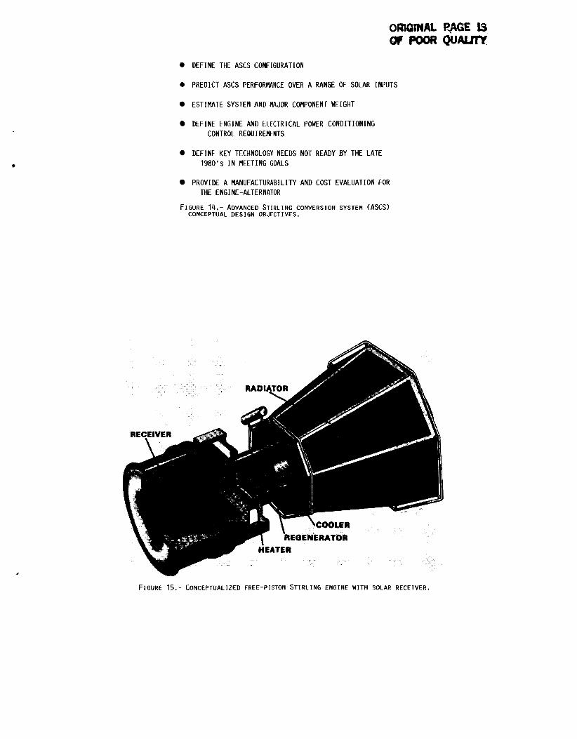
DEFINE THE ASCS CONFIGURATION
0 PREDICT ASCS PERFORMANCE OVER A RANGE OF SOLAR INPUTS
ESTIMATE SYSTEM AND MAJOR COMPONENT WEIGHT
DEFINE ENGINE AND ELECTRICAL POWER CONDITIONING CONTROL REQUIREMENTS
DEFINE KEY TECHNOLOGY NEEDS NOT READY BY THE LATE 1980's I N MEETING GOALS
PROVIDE A MANUFACTURABILITY AND COST EVALUATION FOR THE ENGINE-ALTERNATOR
FIGURE 14.- ADVANCED STIRLING CONVERSION SYSTEM (ASCS) CONCEPTUAL DESIGN OBJECTIVES.
FIGURE 15.- CONCEPTUALIZED FREE-PISTON STIRLING ENGINE WITH SOLAR RECEIVER,

1. Report No.
NASA TM-88895
17. Key Words (Suggested by Author@))
2. Government Accession NO.
18. Distribution Statement
4. Title and Subtitle
Free-piston; S t i r l i n g engine; Space power
Overview o f the 1986 Free-Piston S t i r l i n g A c t i v i t i e s a t NASA Lewis Research Center
Unc lass i f i ed - u n l i m i t e d STAR Category 85
7. Author@)
Donald L. A lger
21. No. of pages 19. Security Classif. (of this report) 20. Security Classif. (of this page)
Unc lass i f ied Unc lass i f i ed
9. Performing Organization Name and Address
Nat iona l Aeronautics and Space Admin is t ra t ion Lewis Research Center Cleveland, Ohio 44135
22. Price'
A02
2. Sponsoring Agency Name and Address
Nat ional Aeronautics and Space Admin is t ra t ion Washington, D. C. 20545
3. Recipient's Catalog No.
5. Report Date
6. Performing Organization Code
506-41 -31 8. Performing Organization Report No.
E-331 2
10. Work Unit No.
11. Contract or Grant No.
13. Type of Report and Period Covered
Technical Memorandum
14. Sponsoring Agency Code
5. Supplementary Notes
Prepared f o r t he Twenty-fourth Automotive Technology Development Cont rac tors ' Coord inat ion Meeting sponsored by the U.S. Department o f Energy, Dearborn, Michigan, October 27-30, 1986.
6 Abstract
An overview o f the Nat ional Aeronautics and Space Admin is t ra t ion (NASA) Lewis Research Center 's f ree -p i s ton S t i r l i n g engine a c t i v i t i e s I s presented. These a c t i v i t i e s inc lude work e f f o r t s t o improve and advance the design o f f ree -p i s ton S t i r l i n g engines f o r use i n s p e c i f i c space power app l i ca t i ons . e f f o r t s a r e a pa r t o f the SP-100 program being conducted t o support t he Depart- ment o f Defense (DOD) , Department o f Energy (DOE) and NASA. Such work e f f o r t s inc lude: (1) the t e s t i n g and improvement o f 25 kWe S t i r l i n g Space Power Demon- s t r a t o r Engine (SPDE), (2 ) t he p re l im ina ry design o f 25 kWe s ing le -cy l i nde r Experimental S t i r l i n g Space Engine (ESSE), and ( 3 ) a study t o determine the f e a s i b i l i t y o f sca l ing a s ing le -cy l i nde r f ree -p i s ton S t i r l i n g eng ine / l inear a l t e r n a t o r t o 150 kWe. w i l l be descr ibed which are d i r e c t e d toward t h e advancement o f general f ree - p i s t o n S t i r l i n g engine technology and a p p l i c a t i o n o f t h a t technology i n s p e c i f i c t e r r e s t r i a l app l i ca t i ons . One such work e f f o r t , supported by DOE/Oak Ridge Nat iona l Laboratory (ORNL), i s t he technology development o f a f ree -p i s ton S t i r l i n g engine which produces hyd rau l i c power. F i n a l l y , a t e r r e s t r i a l so la r a p p l i c a t i o n t h a t invo lves a conceptual design o f a 25 kWe so la r Advanced S t i r l i n g Conversion System (ASCS) capable of d e l i v e r i n g power t o an e l e c t r i c u t i l i t y g r i d w i l l be discussed. Laboratory (SNLA) .
These work
Other NASA Lewis f ree -p i s ton S t i r l i n g engine a c t i v i t i e s
This so la r work i s supported by DOE/Sandia Nat iona l