Embed Size (px)
Citation preview

© 2017 Mitsubishi Hitachi Power Systems Americas, Inc. All Rights Reserved.
Proprietary and Confidential Information. This document or information cannot be reproduced, transmitted, or disclosed without prior written consent of
Mitsubishi Hitachi Power Systems Americas, Inc.
SCAQMD AWMA Annual Regional Meeting
Overview of SCR Technology and Retrofitting of SCR’s
to Comply with Upcoming NOx BARCT Standards for
Electric Power Generating Units (EGUs)
Robert McGinty
Senior Product Manager
Gas Turbine & Industrial SCR Systems
1

© 2017 Mitsubishi Hitachi Power Systems Americas, Inc. All Rights Reserved.
Corporate Qualification
Innovative & Improved Technical Advances
(System Design, Catalyst, Modeling)
Validation of Innovation
(Reference Plants - Historical Performance)
Presentation Overview
© 2017 Mitsubishi Hitachi Power Systems Americas, Inc. All Rights Reserved.
Advanced Hot SCR Systems For Frame Simple Cycle Gas Turbines
US Reference Validating “LAER” SCR Systems for Large Frame Class Turbines
Expertise’ built over 40 years with >1000 SCR systems worldwide
(Original Pioneer of SCR Technology)
Leader in Gas Turbine & SCR Technology
Ultra Low NOx Demonstrating All BACT & LAER Requirements
Time Tested Frame SCGT Hot SCRs Spanning 25 Years
Demonstrated High Temperature SCR Systems for SC Frame GT’s
Patented Tempered Air Systems for SC Frame Turbines
OEM - Producing Both Gas Turbine and SCR Systems
Largest US Peaking Plant with Hot SCR Systems
Numerous 1st in Class Innovative Technologies
Most Advanced Class SCR System for Frame SC Gas Turbines
Reference Plant for FERC, Validating High Temp Hot SCR Systems
NRG Marsh Landing SCRs for Large Frame Simple Cycle GTs
© 2017 Mitsubishi Hitachi Power Systems Americas, Inc. All Rights Reserved.
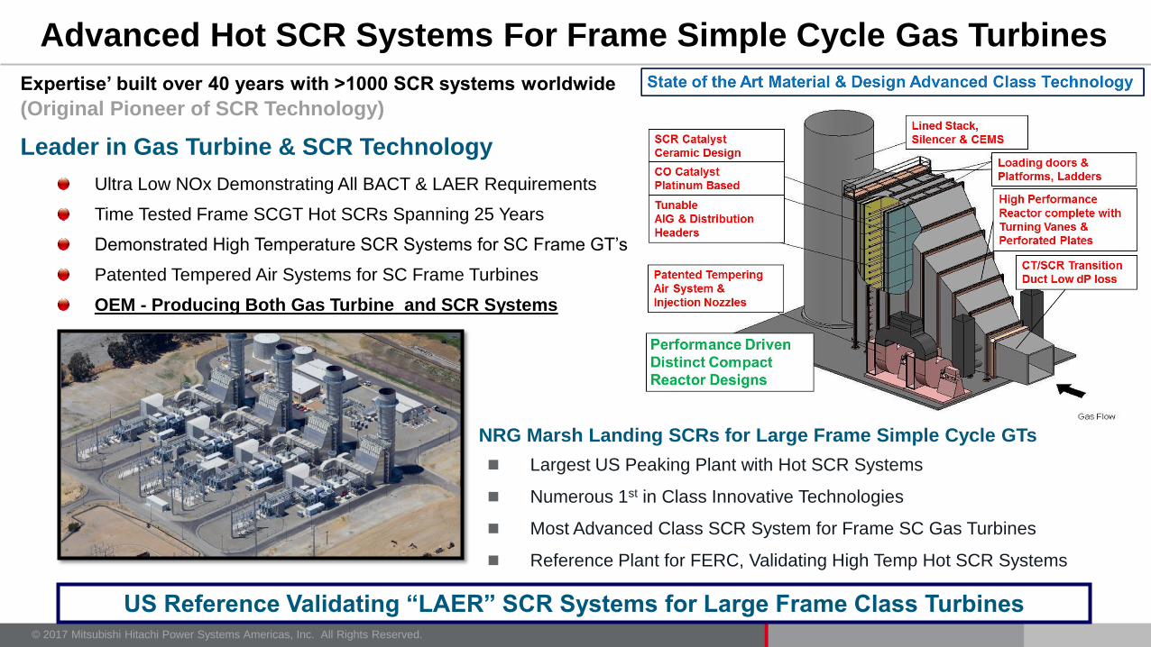
MHPS ONLY Experienced OEM who can wrap both the Gas Turbine and the SCR
for Simple Cycle Applications to meet Current and Future Environmental Regulations
Leader In Gas Turbine and SCR Technology
MHPS - Tomorrow’s Power Plant, Today
Multiple Models
J/G/H/FT
w/ Hot SCR BACT LAER*
9 ppm ≤2 ppm 2-25 ppm <2.5 ppm
15 or 25 ppm ≤2 ppm
Advanced Class Gas Turbines Hi Temp Hot SCR
NO
x
*Requirement in
Nonattainment
Regions
(and growing)

© 2017 Mitsubishi Hitachi Power Systems Americas, Inc. All Rights Reserved.
Key Components of Conventional Hot SCR Systems
Ammonia Injection
Grid
Stack
SCR Catalyst
Ammonia Vaporizing Skid
Ammonia Pump Skid
Ammonia Storage Tank
CO Catalyst
Tempering Air Injection

© 2017 Mitsubishi Hitachi Power Systems Americas, Inc. All Rights Reserved.
CONVENTIONAL SCR & CO/VOC CATALYST MODULES
WIDE ARRAY OF CATALYST SELECTION ENSURES BEST FIT APPLICATION

© 2017 Mitsubishi Hitachi Power Systems Americas, Inc. All Rights Reserved.
Large operating temperature range (350 - >1100oF)
70%
80%
90%
100%
500 600 700 800 900 1000 1100
Temperature [oF]
NO
x R
emov
al E
ffic
ienc
y
Zero V2O5
Low V2O5
High V2O5
NO = 50 ppmvd
NH3/NO = 1.25
O2 = 15.0%
H2O = 7.0%
Zero V2O5
Low V2O5
High V2O5
At higher temps, reduce V:W ratio
Stronger NH3 adsorption
Lower NH3 decomp rate
Higher DeNOx rate
Lower sintering rate
• High temp catalyst:
900F ~ >1,100F
• Medium-high temp catalyst:
800F ~ 900F
• Medium (Standard) catalyst:
450F ~ 800F
Extruded catalyst
consistently demonstrates
uniform cell sizing and
pressure drop prediction

© 2017 Mitsubishi Hitachi Power Systems Americas, Inc. All Rights Reserved.
• Platinum or other PGM promotes
CO to CO2 oxidation. May be
temperature sensitive to PGM type
• Substrate may be brazed joint
corrugated metallic foils, stacked
corrugated foil or ceramic cells.
• Typically high density CPSI
substrate employed to provide high
surface area per cu.ft. of catalyst
• Oxidation occurs on “surface” of
catalyst at active sites
• Pressure drop is directly dependent
on catalyst depth and compactness
Conventional CO & VOC Catalyst

© 2017 Mitsubishi Hitachi Power Systems Americas, Inc. All Rights Reserved.
KEY CONSIDERATIONS FOR FUTURE BARCT (EXISTING UNITS)
Existing vs. Future NOx Levels Increased Catalyst Performance
Flue Gas and Ammonia Distribution CFD Modeling for Reduced
Deviation of Velocity & Distribution
Increased Catalyst Loading Reactor Area for Added Catalyst,
Sealing System to Prevent Bypass
Catalyst Configuration Consideration Application Dual Purpose Catalyst
Advanced Catalyst Geometry
Increased Ammonia Flow High Density Ammonia Injection
Increased Balancing Valve Array
Increased Ammonia Vaporization Retrofit or Replace – AFCU
Retrofit or Replace Ammonia FPS
BEST AVAILABLE RETROFIT CONTROL TECHNOLOGY (BARCT)

© 2017 Mitsubishi Hitachi Power Systems Americas, Inc. All Rights Reserved.
Example of Advanced Catalyst Configuration, Geometry, Performance
Step-change reduction in pressure drop: 60–75% Lower!
Vastly improved emission control solution capability for NOx, CO, NH3 slip
Innovative seal to prevent need for maintenance
+ +
Pleated Module Advanced Catalyst Potential
60% Higher
Integrated Seal
Result:
0
0.5
1
1.5
2
Legacy New
Potential / Volume
Combines three new tools
Patent Pending
Information courtesy of Cormetech
Platform

© 2017 Mitsubishi Hitachi Power Systems Americas, Inc. All Rights Reserved.
Single Zone Catalyst Reactor for Combined or Simple Cycle
AIG METEOR™
Homogeneously extruded honeycomb catalyst (1 layer)
SCR functionality
V2O5-WO3/TiO2
Oxidation functionality
PGM (Pd and/or Pt)
Simplicity of one catalyst layer vs. two
Smaller footprint in HRSG
Lower pressure drop
Lower capital and O&M costs
Flexibility
applicable to new units, retrofits, and
replacements
Lower SO2 oxidation rate
Potential for reduced backend fouling
Highly resistant to sulfur, compounds in
the flue gas
Broader load flexibility from reduced
sensitivity to sulfur fouling agents when
operating at low temperature
Lower Pressure Drop
improved power output
reduced fuel costs Information courtesy of Cormetech

© 2017 Mitsubishi Hitachi Power Systems Americas, Inc. All Rights Reserved.
Catalyst Poisoning & Degradation Mechanisms
Degradation Source Mechanism
High Temperature Decreases available surface area by thermal sintering of ceramic or
washcoat material
Fine particulate Reduces available surface area by masking surface and preventing
diffusion into pre structure
Ammonia-sulfur compounds Plugs pores and prevents diffusion
Alkaline metals, Na, K Ion exchange with active sites
Alkaline earth metals, Ca, Mg Typically in form of sulfates, bond with acid sites reducing the ability of
catalyst to absorb NH3 I.e. formation of CaSO4
Halogen May react with and volatilize active metal sites
Arsenic Gaseous arsenic diffuses into catalyst and covers active sites,
preventing further reaction
V, Pt, Cr and Family Deposit onto catalyst, increasing NH3 to NO and/or SO2 to SO3

© 2017 Mitsubishi Hitachi Power Systems Americas, Inc. All Rights Reserved.
MHPS Flow Modeling – Validates Design – Minimizes Risk
13
1) Develop flow distribution devices and injection ports to;
a) Achieve acceptable velocity distributions through CO and SCR catalyst:
b) Achieve acceptable ammonia distribution at the inlet to the SCR catalyst:
c) Achieve acceptable temperature distributions at the catalyst inlets:
2) To determine from model measurements the system pressure loss for the final configuration
• Typical Boundaries: Turbine Diffuser or Process Equipment Exhaust Outlet through Stack Outlet.
• CFD and CFM results, validates ammonia injection design, ammonia mixing devices, tempering air
distribution through injection ports, turning vanes, perforated plates and flow straightening devices.

© 2017 Mitsubishi Hitachi Power Systems Americas, Inc. All Rights Reserved.
Tempering Air & Ammonia Mixing Challenges
- Major Design Concern;
a) Short Distance Available to Mix the Air
b) Conflicting requirement at the inlet duct
Mix the air into flue gas (Turbulence)
versus
Uniform gas flow necessary at CO catalyst face.
versus
Homogeneous ammonia mix in flue gas at SCR catalyst face
(Flow Straightening & Velocity Normalizing at Catalyst)
Challenging Turbine Exhaust Conditions – Typical
Flue gas exiting turbine diffuser up to ~140 FPS
Tempering air ~ 30% total flue gas volume
High exhaust gas temperature ~ 1200 def.
Contrasting optimum catalyst temperature profiles CT
SCR cata
CO cata
© 2017 Mitsubishi Hitachi Power Systems Americas, Inc. All Rights Reserved.
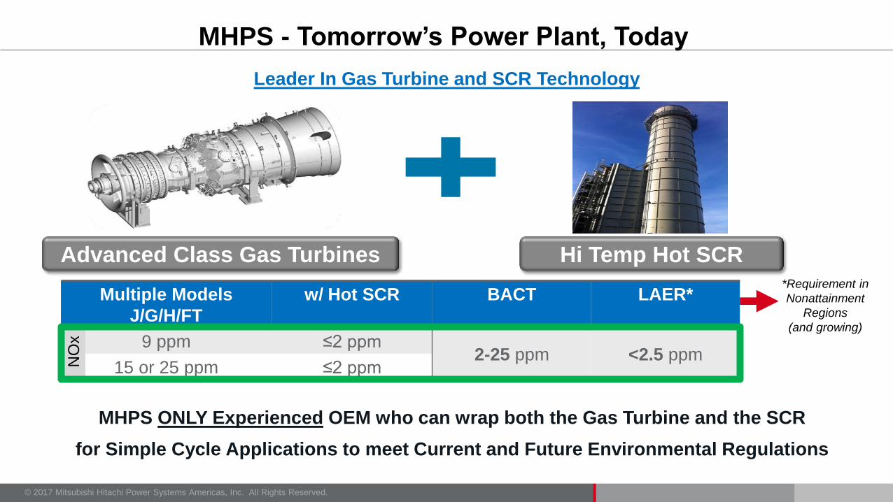
VAPORIZED NH3
EXHAUST
DUCT
LANCE PANELS
BALANCING
MANIFOLD
• Double reactor side entry balancing valve manifold to fine tune AIG
• Lance panels allows expedient optimization
• High density drilling, dense ammonia injection pattern
• Orifice flow measurements validate ammonia panel flow field balance
• Allows for future optimizing as catalyst ages or turbine performance degrades
Represents most responsive balancing
approach, easy to adjust and fastest
response, does require additional
piping, valves and manifolds
Multi-Zone
A Core Technical Attribute Facilitating Less Than 2PPM NOx & Low Ammonia Slip

© 2017 Mitsubishi Hitachi Power Systems Americas, Inc. All Rights Reserved.
Catalyst Sealing Mechanism – Good & Bad Comparison
© 2017 Mitsubishi Hitachi Power Systems Americas, Inc. All Rights Reserved.
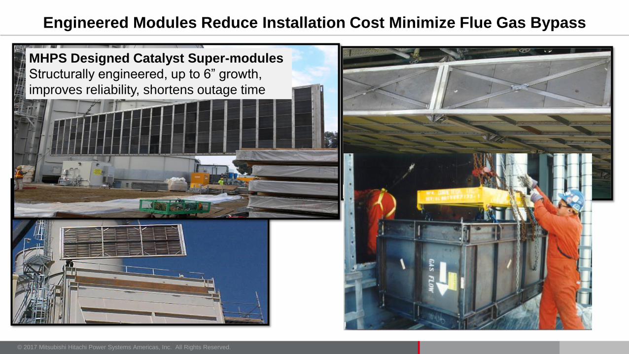
Engineered Modules Reduce Installation Cost Minimize Flue Gas Bypass
MHPS Designed Catalyst Super-modules
Structurally engineered, up to 6” growth,
improves reliability, shortens outage time
© 2017 Mitsubishi Hitachi Power Systems Americas, Inc. All Rights Reserved.
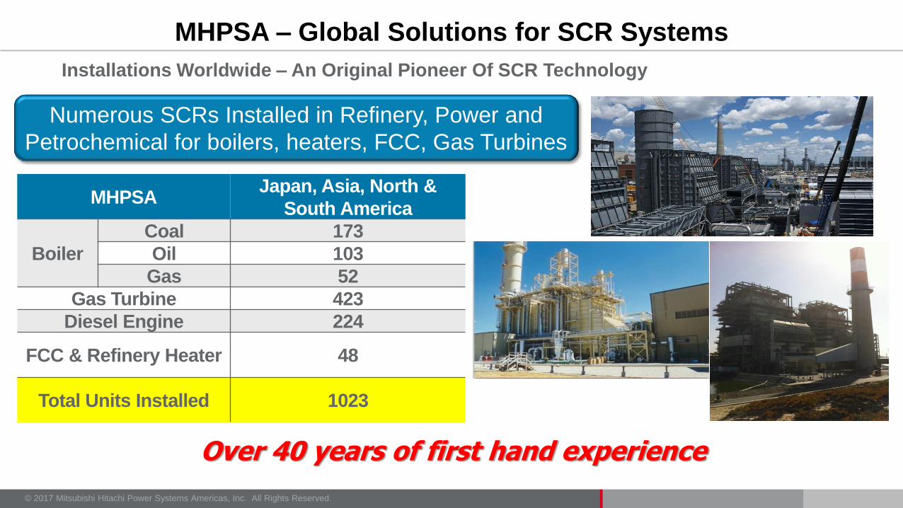
Installations Worldwide – An Original Pioneer Of SCR Technology
MHPSA – Global Solutions for SCR Systems
MHPSA Japan, Asia, North &
South America
Boiler
Coal 173
Oil 103
Gas 52
Gas Turbine 423
Diesel Engine 224
FCC & Refinery Heater 48
Total Units Installed 1023
Over 40 years of first hand experience
Numerous SCRs Installed in Refinery, Power and
Petrochemical for boilers, heaters, FCC, Gas Turbines

© 2017 Mitsubishi Hitachi Power Systems Americas, Inc. All Rights Reserved.
Project K-Point SMUD
McClellan
TEPCO
Yokosuka
Carson
IceGen
NRG
Marsh
Landing
Calpine
Mickleton
Calpine
Carll’s
Corner
PNM
La Luz
CT M701F GE 7EA M701DA LM 6000 SGT6
5000F W501AC
P&W
FT 4
TwinPac
LM6000
Gas Temp
Deg. F 1112 1020 986 875 1146 900 900 <900
Minimum
DeNOx Eff. 86% 90% 60% 90% 87% 75% 76% >94%
Start of
Operation
Jul.
1992
Apr.
2004
Aug.
1992 June 1995
Apr.
2013
May
2015
May
2015 Nov. 2015
Turbine Type Frame Frame Frame Aero Frame Frame Aero Aero
Tempering Air
Fan YES NO NO NO YES NO NO Yes
Wide Range of Gas Turbine Models and Temperature Variations

© 2017 Mitsubishi Hitachi Power Systems Americas, Inc. All Rights Reserved.
‘Knowledge’ and ‘Expertise’ built over the past 40 years
(Developer of honeycomb catalyst, plate catalyst, ammonia grid and ammonia vaporizing system technology)
Successfully completed the most difficult and challenging projects for Frame & Aero GT’s, Refinery
FCCs, Process Heaters, Thermal and Power Boilers
Ultra Low NOx & Slip (< NOx 2ppm/NH3 2ppm)
Zero-Slip ammonia systems
High temperature SCR systems SCGT’s
Tempered air systems for SC Frame Turbines
More than 1000 SCR systems world wide
Proven track record. (translates to Low Risk)
Have always met or exceeded performance guarantees
Only OEM supplier of SCR catalyst and SCR systems
We do not walk away
Competitive offerings, high reliability systems
Experienced teams in the USA, Japan R&D Centers
Financial stability
MHPS – A World Leader of Intelligent Engineered SCR Systems

© 2017 Mitsubishi Hitachi Power Systems Americas, Inc. All Rights Reserved.
Thank You
21
Robert McGinty
Mitsubishi Hitachi Power Systems
Senior Product Manager
Gas Turbine and Industrial SCR Systems
Office: 949-856-8419 Mobile: 949-633-8614
© 2017 Mitsubishi Hitachi Power Systems Americas, Inc. All Rights Reserved. 22