Embed Size (px)
Citation preview

1
���������� � � � � �� � � ��� � � �� � �� � � � � �� � �� � �� � � �
Overview of High Speed Network Technologies
PASI (Pan-American Advanced Studies Institute)
Grid Computing and Advanced Networking Technologies for e-Science
Tereza Cristina M. B. CarvalhoANSP/LARC/PCS/EPUSP
���������� � � � � �� � � ��� � � �� � �� � � � � �� � �� � �� � � �
Agenda
� Why High-Speed Networks?
� Switching Techniques
� Circuit Switching.
� Packet Switching.
� Cell Switching
� High-Speed Network Technologies.
� ATM
� MPLS
� IP Networks.
� Final Considerations

2
���������� � � � � �� � � ��� � � �� � �� � � � � �� � �� � �� � � �
Why High-Speed Networks?
� Optical Network Development
� Multimedia Application.
���������� � � � � �� � � ��� � � �� � �� � � � � �� � �� � �� � �
Network Evolution
���������� ���������������� ����
��������� ���� � � �
� ����� ������� ���� ��������� �
��!������ �
� ����� ������� �
��������� �
��!������ �
��������� ��" � ���#�$ ��% ��$�!
��!������ ��� &���
' #�����(��
)��#��
������
* ���������
������

3
���������� � � � � �� � � ��� � � �� � �� � � � � �� � �� � �� � �
Multimedia Applications
� Simultaneous and integrated usage of data, sound and video, aiming to get more efficient and interactive interface.
���������� � � � � �� � � ��� � � �� � �� � � � � �� � �� � �� � � !
Types of Multimedia Applications
� The main types of multimedia applications are:
� Conversational services.
� Retrieval services.
� Messaging services.
� Distribution services.

4
���������� � � � � �� � � ��� � � �� � �� � � � � �� � �� � �� � � "
Conversational Services
� Allow the mutual exchange of data, whole documents, pictures and sound in real-time:
� Videotelepony.
� Videoconference.
� Real-time transmission of multimedia objects (medical images, remote games, among others).
� Virtual reality systems.
���������� � � � � �� � � ��� � � �� � �� � � � � �� � �� � �� � � #
Retrieval Services
� These services are used, for instance, to obtain video filmsat any time or to acess remote software library.
� Electronic library.
� Video On-demand:
� For entertainment purposes.
� Remote education and training.
� Medical image communications.
� Professional image communications.

5
���������� � � � � �� � � ��� � � �� � �� � � � � �� � �� � �� � � $
Messaging Services
� Include mailboxes services for the transfer of sound, pictures and/or documents.
� No real-time applications.
� Video mail services (transfer of moving pictures andaccompanying sound).
� Multimedia mail services (tranfer of mixed documentscontaining text, graphics, still and moving picturesinformation as well voice annotations).
���������� � � � � �� � � ��� � � �� � �� � � � � �� � �� � �� � � ��
Distribution Services
� These services are classified as:
� Services without user presentation control:
� Distribution of video/audio signals.
� Electronic publishing such as electronic newspaper..
� TV program distribution.
� Services without user presentation control:
� Remote education and training.
� Tele-advertising.

6
���������� � � � � �� � � ��� � � �� � �� � � � � �� � �� � �� � � ��
Multimedia Application Requirements
���������� � � � � �� � � ��� � � �� � �� � � � � �� � �� � �� � � ��
Multimedia Application Requirements
VoiceDelay = 400msEco <= 100msReproduction125 µµµµs
Compressed HDTV from 20 Mbps

7
���������� � � � � �� � � ��� � � �� � �� � � � � �� � �� � �� � � ��
Quality of Service for Multimedia Applications
� Different multimedia applications work properly on different QoSparameters.
L: Low; H: High; VH: Very High.
Application Requireme
nts
Data GraphicData
Voice Interactive Voice
Video Real-Time Video
Bandwidth L H H H VH VH
Delay L L H VH H VH
Delay Variation
L L H VH H VH
Error Rate H VH L L L/H VH/
���������� � � � � �� � � ��� � � �� � �� � � � � �� � �� � �� � � �
Normally, the high-speed networks support multimedia applications guaranteeing the Quality of Service parameter
compliance.
8
���������� � � � � �� � � ��� � � �� � �� � � � � �� � �� � �� � � �
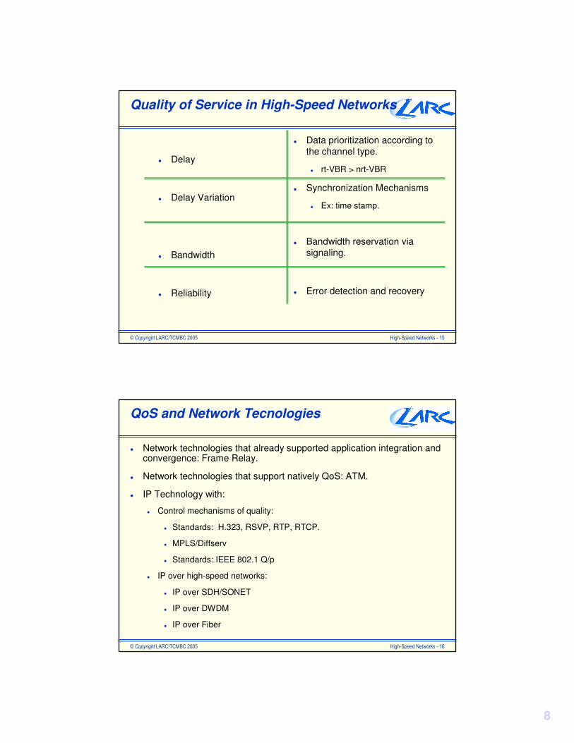
Quality of Service in High-Speed Networks
� Delay
� Delay Variation
� Bandwidth
� Reliability
� Data prioritization according to the channel type.
� rt-VBR > nrt-VBR
� Synchronization Mechanisms
� Ex: time stamp.
� Bandwidth reservation via signaling.
� Error detection and recovery
���������� � � � � �� � � ��� � � �� � �� � � � � �� � �� � �� � � �!
QoS and Network Tecnologies
� Network technologies that already supported application integration and convergence: Frame Relay.
� Network technologies that support natively QoS: ATM.
� IP Technology with:
� Control mechanisms of quality:
� Standards: H.323, RSVP, RTP, RTCP.
� MPLS/Diffserv
� Standards: IEEE 802.1 Q/p
� IP over high-speed networks:
� IP over SDH/SONET
� IP over DWDM
� IP over Fiber

9
���������� � � � � �� � � ��� � � �� � �� � � � � �� � �� � �� � � �"
Switching Techniques
���������� � � � � �� � � ��� � � �� � �� � � � � �� � �� � �� � � �#
Network = Resource Sharing
Physical Media(Multiplexing Mechanisms)
Equipment Infrastructure(Switching Mechanisms)
•Frequency.
•Time.
•Circuits
•Packets
•Cells
���������������� �������������������������������������������������������������� ���������� �������
Switching Techniques

10
���������� � � � � �� � � ��� � � �� � �� � � � � �� � �� � �� � � �$
Communication Networks
11
55
77
44
22
33
66
Nodes
CommunicationNetwork
FF
AA
DD
EE
BB
CC
Communication network is a system composed of nodes connected through transmission links that provide a path between any two
nodes of the network.
Link
���������� � � � � �� � � ��� � � �� � �� � � � � �� � �� � �� � � ��
Switching
� In a network, the information is sent from one node to another until reaching its destiny.
� In each node, the incoming information that arrives at an input port is transferred to an output port that is more proper to reach its destiny.
� The output port is defined taking as basis the information of the switching tables.
� The information transfer from one input port to an output port is called switching.
12
3
A
B
CNode
A 1B 2C 3
DestinyOutput Port
Destiny = B

11
���������� � � � � �� � � ��� � � �� � �� � � � � �� � �� � �� � � ��
Switching Techniques
� There are different types of switching techniques.
� The two most known switching techniques are:
� Circuit Switching does keep the resources reserved through the whole communication path before transmitting the information.
� Packet Switching does not keep the resources reserved through the whole communication path before transmitting the information.
���������� � � � � �� � � ��� � � �� � �� � � � � �� � �� � �� � � ��
Evolution of the Switching Techniques
� One one side, the circuit switching technique requires lower processing complexity of its nodes and supports constant bit rate (CBR - Constant Bit Rate).
� On other hand, the packet switching technique requires higher processing complexity of its nodes and provides greater flexibility, supporting also bursty traffic and variable bit rate (VBR - Variable Bit Rate).
Switching Techniques
Cell Switching
(ATM)
Fixed Bit Rate
Simplicity
Variable Bit Rate
Complexity
PacketSwitching
CircuitSwitching
MultirateCircuit
Switching
FrameRelay

12
���������� � � � � �� � � ��� � � �� � �� � � � � �� � �� � �� � � ��
Circuit Switching
� Examples of networks based on circuit switching technique:
� PSTN – Public Switched Telephone Network
� ISDN - Integrated Services Digital Network
� Cell Phone Network
���������� � � � � �� � � ��� � � �� � �� � � � � �� � �� � �� � � �
Circuit Switching
� The communication in a switched circuit network is performed in three phases:
� Circuit Establishment
In a telephone network, the resources are allocated when we callthe destiny number.
� Data Transfer
Conversation period.
� Circuit Release
Telephone disconnection.
� The circuit establishment and release are performed through a signaling mechanism between the nodes and imply some delay.

13
���������� � � � � �� � � ��� � � �� � �� � � � � �� � �� � �� � � �
A
B C
D
E F
Computer A
Computer B
Computer C
Computer D
Switching Node
����������
��
A B C D
�������
�������
���������� � � � � �� � � ��� � � �� � �� � � � � �� � �� � �� � � �!
Circuit Switching Characteristics
� The connection resources are kept allocated, even when there is no data being transferred.
� If there is no enough resources for a connection establishment, the connection request is blocked or denied.
� The delay in each node is not meaningful.
� It is not well-suited for bursty traffic.
� It is proper for transmission of isochronous signals, such as voice and video.
� Isochronous traffic - the received data has to be reproduced at the same rate of its generation.

14
���������� � � � � �� � � ��� � � �� � �� � � � � �� � �� � �� � � �"
Packet Switching
� In packet switching networks, the resources are not previously reserved.
� The resources are allocated on-demand for the packets.
� So, the packets have to wait in a queue if the required resource were not available.
� The main network resource is the link.
� If the output link is already being used, the packet will be kept in a waiting queue and as consequence it will suffer a delay.
� If the waiting queue is full, the incoming packets will be discarded.
� Why packets?
� Long messages monopolize the switch queues.
���������� � � � � �� � � ��� � � �� � �� � � � � �� � �� � �� � � �#
A
Computer A
Computer B
Computer C
Computer D Switching Node
B C
E F
D
Packet 1
Packet 2
Packet 3
Packet 4
Packet 5
A E F D
Packet 1
Packet 2
Packet 3
Packet 4
Packet 1
Packet 2
� ����
�������time

15
���������� � � � � �� � � ��� � � �� � �� � � � � �� � �� � �� � � �$
Packet Switching
Queue
� The packets are kept in a waiting queue if the resource is already being used.
� Long messages monopolize the switch queues.
Queue
���������� � � � � �� � � ��� � � �� � �� � � � � �� � �� � �� � � ��
Packet Switching
� The packet switching networks normally work with a packet maximum size:
� For this reason, the sender has to segment the too long messages in packets before they are sent to the network.

16
���������� � � � � �� � � ��� � � �� � �� � � � � �� � �� � �� � � ��
Characteristics of Packet Switching
� The link capacity is shared among several simultaneous communications.
� The delay in each node is meaningful due to the waiting time of the packets in the queues.
� It is not well-suited for isochronous transmission.
� It is very proper for bursty traffic as that one generated by data computer networks.
� In a packet switching network, the nodes accept the packets even when there is a high workload:
� The packets are kept stored in queues until the necessary resources are available.
� It implies that the delay can increase. The delay is variable and depends on the queue size.
���������� � � � � �� � � ��� � � �� � �� � � � � �� � �� � �� � � ��
Classes of Packet Switching
� There are two classes of packet switching:
� Packet switching oriented to datagram.
� Packet switching oriented to virtual circuit.

17
���������� � � � � �� � � ��� � � �� � �� � � � � �� � �� � �� � � ��
3
4
1
2
1
2
2
3
1
1 23
Packet Switching oriented to datagram
RT. .. .C 3D 4. .
RT. .. .. .C 2. .
RT. .. .. .C 3. .
RT. .. .C 2D 3. .RT = Routing Table
A
B
C
D
R
R
RRC
D
C
DC
C
D
���������� � � � � �� � � ��� � � �� � �� � � � � �� � �� � �� � � �
Packet Switching oriented to virtual circuit
� There are two types of virtual circuits:
� SVC ( Switched Virtual Circuit ) is a virtual circuit created and released on demand through a signaling protocol.
� A special packet, called signaling message, is sent by the sender.
� This message (Packet) passes from one switch to the next one until the destiny, establishing the path (virtual circuit).
� PVC ( Permanet Virtual Circuit ) is a pre-configured virtual circuit.
� The switching tables are manually configured.
� Management systems can be deployed to remotely configure this table.

18
���������� � � � � �� � � ��� � � �� � �� � � � � �� � �� � �� � � �
Packet Switching oriented to virtual circuit
A
B
C
D
SW
SW
SWSW3
4
1
2
1
2
2
3
1
20
1:
:
:
ST 1
15
1:
::
ST 1
32
1:
::
ST 1
2 *3 *
3 *
ST 1 = Switching Table Associated to Port 1
12
3215
20d 15d 32
d
12d
� Example
���������� � � � � �� � � ��� � � �� � �� � � � � �� � �� � �� � � �!
Datagram x virtual circuit
Datagram Virtual Circuit
All packets carry the complete address. The packets carry an identifier
Slow Switching:The routing is performed on demand.
Fast Switching:The routing is pre-performed.
The datagrams can be discarded during congestion periods.
It is possible to avoid congestionduring the virtual circuit establishment.
Examples:
IP, IPX, Ethernet, Token Ring
Examples:
X.25, Frame Relay, ATM, MPLS

19
���������� � � � � �� � � ��� � � �� � �� � � � � �� � �� � �� � � �"
Routing and Switching Tables
� Routing Table is a table that associates destiny addresses to output ports (links).
� It informs the output port to reach the specified destiny address.
� Switching Table is a table that associates a VCI of an input port to a VCI of an output port.
� It indicates to which output port the packets that arrive at some input port should be sent.
� It is built up during the virtual circuit establishment.
� The output port is determined from the routing table.
���������� � � � � �� � � ��� � � �� � �� � � � � �� � �� � �� � � �#
Cell Switching
� Characteristics:
� Evolution of Frame Relay
� based on the very low BER of the current physical media
� Fixed length cells
� processing overhead is reduced
� Dynamic bandwidth allocation
� End-to-end error and flow control are NOT implemented
� Supports constant or variable bit rate services
� Data, voice and video over a single network
� The number of networks needed is reduced

20
���������� � � � � �� � � ��� � � �� � �� � � � � �� � �� � �� � � �$
A
Computer 1
Computer 2
Computer 3
Computer 4
ATM Switch
B C
E
D
F
Cell Switching
cell1
cell 2
cell 3
cell 4
cell 5
A E F 4
cell 1
cell 2
cell 3
cell 4
cell 1
cell 2
cell 3
���������� � � � � �� � � ��� � � �� � �� � � � � �� � �� � �� � � �
Cell Switching
� Advantages:
� Supports data (static and dynamic images), voice and video.
� Allows the combined transfer of different types of information.
� Make possible the integration of different types of networks and communication systems.
� Disadvantages:
� Does not operate in an optimized way for any type of network.
� Requires an infrastructure with low error rate and high transmission rate.

21
���������� � � � � �� � � ��� � � �� � �� � � � � �� � �� � �� � � �
� ������+)$��, ��+% $��$ ���$ +�-�.���#���+� ����$/�0� .�.�+)$�����������������(��+)$����1$������.2
��� �� ������ ������+, ��+��##$���(������//�+��������������.���//�+3 � �������$��������$��$ + ��!���$��+� ��� �����$�������//��� � ��� ��
!����� ������+)$��#�$���� ��1$������.2+4 ������.���1$������.2+3 � ����(� .�.�����$��$ +��##$��$/�.//��� ��#���$/��������
Summaring...
���������� � � � � �� � � ��� � � �� � �� � � � � �� � �� � �� � � �
High-Speed Network Technologies
22
���������� � � � � �� � � ��� � � �� � �� � � � � �� � �� � �� � � �
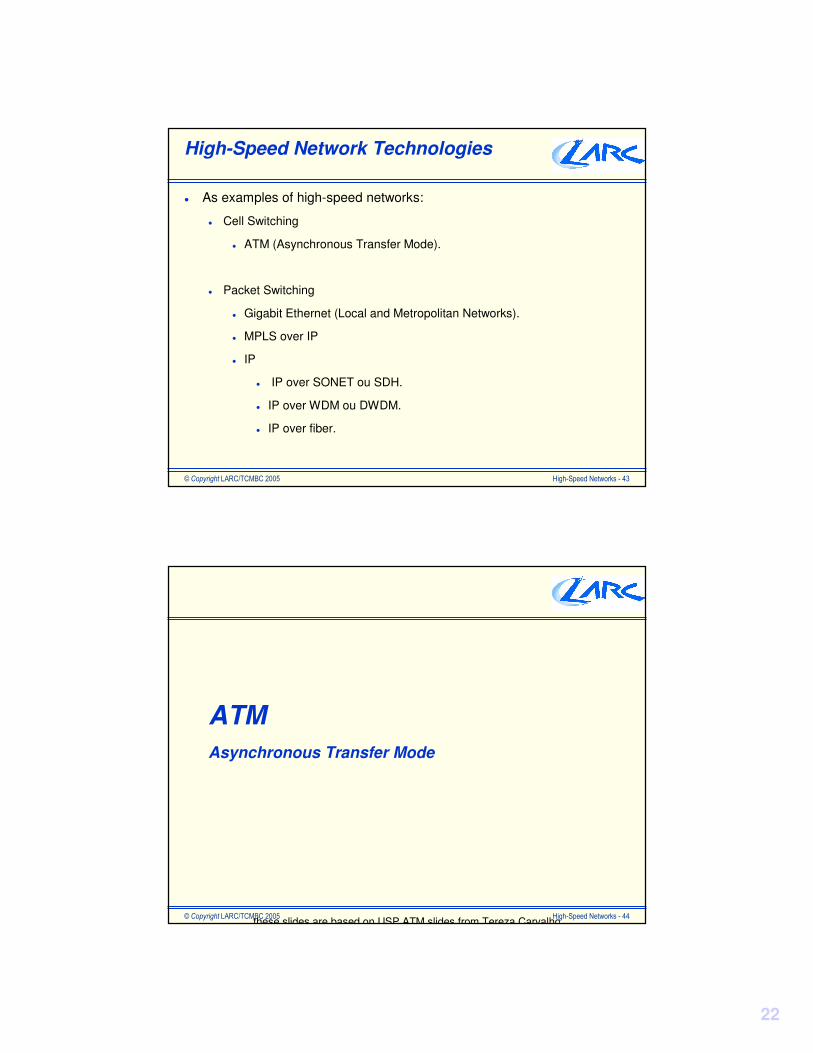
High-Speed Network Technologies
� As examples of high-speed networks:
� Cell Switching
� ATM (Asynchronous Transfer Mode).
� Packet Switching
� Gigabit Ethernet (Local and Metropolitan Networks).
� MPLS over IP
� IP
� IP over SONET ou SDH.
� IP over WDM ou DWDM.
� IP over fiber.
���������� � � � � �� � � ��� � � �� � �� � � � � �� � �� � �� � �
ATMAsynchronous Transfer Mode
these slides are based on USP ATM slides from Tereza Carvalho

23
���������� � � � � �� � � ��� � � �� � �� � � � � �� � �� � �� � �
ATM Basics
� ITU-T approved standard for Broadband ISDN
� packet switching technique with fixed length packets (53 bytes):
� cell switching
� support for multimedia applications (data, voice and video)� transmission media high-speed data links
� ATM service model includes support toconstant bit rate CBR
variable bit rate VBR
available bit rate ABR
���������� � � � � �� � � ��� � � �� � �� � � � � �� � �� � �� � � !
ATM cells
� ATM works with cells
� packets with fixed length - 53 bytes
� 5 bytes for the header + 48 bytes for payload
� some advantages of using cells include
� queuing delay for high-priority cells is reduced
� switching is more efficient
it is easier to implement switching hardware
Header Payload
5 bytes 48 bytes

24
���������� � � � � �� � � ��� � � �� � �� � � � � �� � �� � �� � � "
48 Bytes H
H
48 Bytes48 Bytes 48 Bytes
48 Bytes H
H
48 Bytes48 Bytes 48 Bytes
48 Bytes H
H
48 Bytes48 Bytes 48 Bytes
Text
Voice
Video
A
B
C
A
B
C
Virtual Channel VCI = 1 PRI = 3
Virtual Channel VCI = 2 PRI = 1
Virtual Channel VCI = 3 PRI = 2
VPI = 0
Porteiro
Buffer Interval 8 cells
QoS no ATM:Traffic
Shapping
���������� � � � � �� � � ��� � � �� � �� � � � � �� � �� � �� � � #
ATM Services
� ATM Forum has defined 5 types of services
� CBR Constant Bit Rate
� e.g. uncompressed audio & video
� RT-VBR Real Time Variable Bit Rate
� e.g. real time video conferencing
� NRT-VBR Non-Real Time Variable Bit Rate
� e.g. banking transactions, airline reservation
� ABR Available Bit Rate
� e.g. burst applications (browsing)
� UBR Unspecified Bit Rate
� e.g. data transfer

25
���������� � � � � �� � � ��� � � �� � �� � � � � �� � �� � �� � � $
Multimedia Application Requirements
���������� � � � � �� � � ��� � � �� � �� � � � � �� � �� � �� � � �
ATM – Quality of Service
� Delay and Delay Variation
� Prioritization of different service types:
� CBR, rt-VBR, nrt-VBR, ABR, UBR
� Time Stamp: AAL1 e AAL2.
� Bandwidth
� Bandwidth reservation.
� Reliability
� Congestion control.
� Header error detection and recovery.
� Adaptation Layer.

26
���������� � � � � �� � � ��� � � �� � �� � � � � �� � �� � �� � � �
MPLSMultiProtocol over Label Switching
���������� � � � � �� � � ��� � � �� � �� � � � � �� � �� � �� � � �
MPLS (MultiProtocol Label Switching)
� Corresponds to IETF standard for tag switching.
� The routing is performed deploying the traditional routing protocols such as RIP, OSPF ou BGP. It is possible to use also static routes.
� The switching is performed deploying labels (or tags wit local meaning).
� This technique can be used jointly with ATM networks, associating labels to VPI/VCI.

27
���������� � � � � �� � � ��� � � �� � �� � � � � �� � �� � �� � � �
TSRTSR TSR
TSR
TSR
TDP
Normal routing protocol (OSPF, .. )
Ingress Tagedge routerInsert a tag
Egress tag edge routerremove tag
Swichting based on the tags
Tag Switching
���������� � � � � �� � � ��� � � �� � �� � � � � �� � �� � �� � �
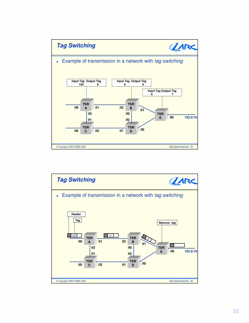
Tag Switching
� Example of transmission in a network with tag switching
Input tag output tag next step output interface
at TSR A 100 6 TSR B if1at TSR B 6 6 TSR E if1at TSR C 17 5 TSR D if2at TSR D 5 6 TSR E if0at TSR E 6 ? TSR E if0
28
���������� � � � � �� � � ��� � � �� � �� � � � � �� � �� � �� � �
Tag Switching
� Example of transmission in a network with tag switching
TSRC
TSRD
TSRE
if0
TSRA
TSRBif0
if0 if0
if0
if1
if1
if1
if1
if2
if2
if2
192.6/16if2
Input Tag Output Tag100 6
Input Tag Output Tag6 6
Input Tag Output Tag6 ?
���������� � � � � �� � � ��� � � �� � �� � � � � �� � �� � �� � � !
Tag Switching
� Example of transmission in a network with tag switching
TSRC
TSRD
TSRE
if0
TSRA
TSRBif0
if0 if0
if0
if1
if1
if1
if1
if2
if2
if2
192.6/16if2
100 66
Header
TagRemove tag

29
���������� � � � � �� � � ��� � � �� � �� � � � � �� � �� � �� � � "
MPLS (MultiProtocol Label Switching)
� Uses the tag switching technique.
� Uses prioritization mechanisms.
� The packet priority is define by the TOS (Type Of Service)field containing in the IP packet header.
� 8 different classes of service are defined.
� This field is initiated by the edge switches. In this case, all switches work with different queues with different priorities.
� These switches can also implement congestion control mechanisms. In the case of congestion, the network request to its end-nodes to reduce the generated traffic.
���������� � � � � �� � � ��� � � �� � �� � � � � �� � �� � �� � � #
MPLS (MultiProtocol Label Switching)
� MPLS allows the creation of different information flows with different service classes.
LSRC
LSRD
LSRE
LSRA
LSRB
LSR - Label Switching Router
VideoServer
FileServer
VideoFlow
DataFlow

30
���������� � � � � �� � � ��� � � �� � �� � � � � �� � �� � �� � � $
Diffserv (Differentiated Service)
� It is used to define different service classes that can be associated to different values of the IP packet field -TOS (Type Of Service), or DS (Differentiated Services) as it is called in the case of DiffServ.
� The services classes are:
� Premium Service: for applications with low delay and delay variation. For instance: IP Phone, Videoconference e Virtual Private Lines over VPNs.
� Assured Service:for applications that require nore reliability than the Best Effort Service.
� Oympic Service: provide 3 levels of service with different quality:
� Gold, Silver e Bronze.
���������� � � � � �� � � ��� � � �� � �� � � � � �� � �� � �� � � !�
Diffserv (Differentiated Service)
� The DiffServ can be used with MPLS.
� The routers provide QOS and traffic control.
���
� �
�
��������������
����������
���������� ����

31
���������� � � � � �� � � ��� � � �� � �� � � � � �� � �� � �� � � !�
IPIP over SDH/SONETIP over DWDMIP over dark fiber
���������� � � � � �� � � ��� � � �� � �� � � � � �� � �� � �� � � !�
IP over SONET/SDH
64
3rd. level STM - 16
2nd. level STM - 4
1st. level STM - 1
tributaries
Basicchannel
2.488.320
622.080
155.520
6.3122.0481.544
9.953.280 4th. level STM - 64
Basicchannel64
3rd. level STS- 12
2nd. level STS - 3
1st. level STS - 1
tributaries
2.488.320
622.080
155.520
6.3122.0481.544
9.953.280
4th. level STM - 48
51.840
5th. level STM - 192
SDH Hierarchy
SONETHierarchy
40.000.000 5th. level STM - 256
40.000.000 6th. level STM - 768
32
���������� � � � � �� � � ��� � � �� � �� � � � � �� � �� � �� � � !�
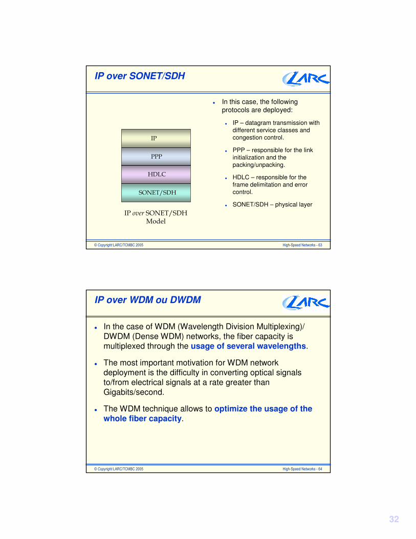
IP over SONET/SDH
� In this case, the following protocols are deployed:
� IP – datagram transmission with different service classes and congestion control.
� PPP – responsible for the link initialization and the packing/unpacking.
� HDLC – responsible for the frame delimitation and error control.
� SONET/SDH – physical layer
����� ��!
!��
�
� ����� ����� ��!� ����
���������� � � � � �� � � ��� � � �� � �� � � � � �� � �� � �� � � !
IP over WDM ou DWDM
� In the case of WDM (Wavelength Division Multiplexing)/ DWDM (Dense WDM) networks, the fiber capacity is multiplexed through the usage of several wavelengths.
� The most important motivation for WDM network deployment is the difficulty in converting optical signals to/from electrical signals at a rate greater than Gigabits/second.
� The WDM technique allows to optimize the usage of the whole fiber capacity.

33
���������� � � � � �� � � ��� � � �� � �� � � � � �� � �� � �� � � !
IP over WDM ou DWDM
� In the case of DWDM, it is possible to have for instance:
� 2,5 Gbps Channels:
� 16 Channels = 40 Gbps.
� 24 Channels = 60 Gbps.
� 40 Channels = 100 Gbps.
� 80 Channels = 200 Gbps.
� 10 Gbps Channels:
� 4 Channels = 40 Gbps.
� 16 Channels = 160 Gbps.
� 128 Channels = 1280 Gbps.
���������� � � � � �� � � ��� � � �� � �� � � � � �� � �� � �� � � !!
IP over Fiber
� Other option is to deploy IP over dark fiber.
� In this case, the transmission and the reception of the optical signals can be performed by the routers.
� It can be used in limited geographical areas (It is supposed no usage of regenerators).
� There is a very good usage of the fiber transmission capacity.
� It supports bandwidth scalability.

34
���������� � � � � �� � � ��� � � �� � �� � � � � �� � �� � �� � � !"
Multimedia Application Requirements
���������� � � � � �� � � ��� � � �� � �� � � � � �� � �� � �� � � !#
IP and QoS
� Delay and Delay Variation
� Prioritization of different service types.
� Time Stamp: RTP (Real Time Protocol) and RTCP (Real Time ControlProtocol).
� Transmission Bandwidth
� Bandwidth Allocation: RSVP
� Reliability
� Congestion Control.
� Error Recovery by TCP or any application.

35
���������� � � � � �� � � ��� � � �� � �� � � � � �� � �� � �� � � !$
Final Considerations
� The concept of high-speed networks has changed very fast with the technology advances:
� The optical fiber is one of the most important change factor.
� As consequence, new types of applications have become possible.
� The Internet 2 community concentrates research related to:
� Optical networks as Reuna, Giga, Kyatera, Lambda-Rail, Geant-2.
� Advanced Applications:
� Grid Computing (infra-structure).
� e-Science.
� e-Medicine.
� e-learning.
���������� � � � � �� � � ��� � � �� � �� � � � � �� � �� � �� � � "�
Acknowledgments
Thanks to:Prof. Stephan Kovach and Denis Gabus from the Network and Computer Architecture Laboratory (LARC) from the Department of Computer Engineering - Escola Politécnica - Univ. of Sao Paulo
(USP) - Brazil