Embed Size (px)
Citation preview

OVERVIEW OF DIRECT FIXATION FASTENERS in MAJOR U.S. TRANSIT SYSTEMS
Korhan Ciloglu & Robert Alsop
L.B. FOSTER COMPANY
2018 INTERNATIONAL CROSSTIE AND FASTENING SYSTEM SYMPOSIUMUniversity of Illinois at Urbana Champaign
May 15, 2018

Introduction & Overview• Direct fixation track is also known as ballastless track Non-embedded
Embedded
• Original use of direct fixation fasteners (DFF) date back 1920s in NYC
• Increased use of slab track design in urban areas in the second half of 20th century
(e.g. MARTA, BART, WMATA)
• New fastening systems were needed to accommodated slab track design and
construction
• Numerous designs were created over the years in the US and globally, all aiming to:
Maintain track integrity under operational loads
Offer noise and vibration mitigation
Insulate rails electrically
2
3
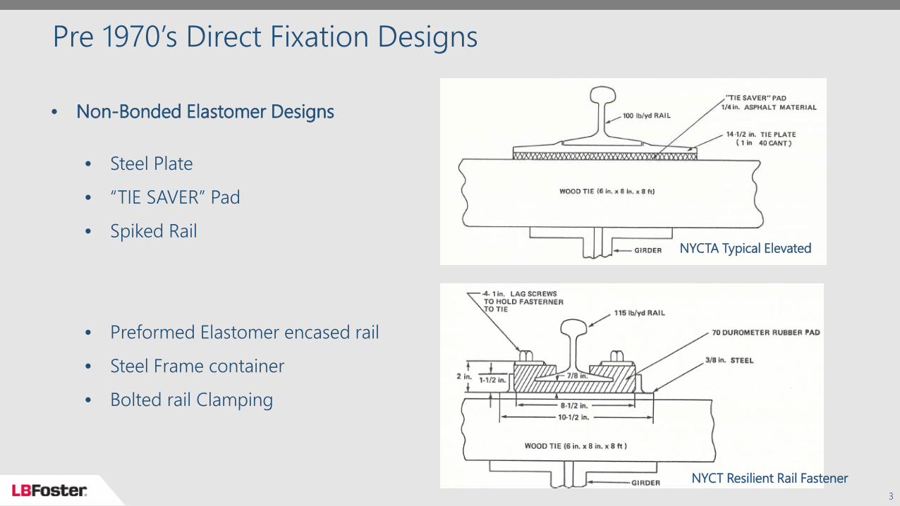
Pre 1970’s Direct Fixation Designs
NYCT Resilient Rail Fastener
NYCTA Typical Elevated
• Non-Bonded Elastomer Designs
• Steel Plate
• “TIE SAVER” Pad
• Spiked Rail
• Preformed Elastomer encased rail
• Steel Frame container
• Bolted rail Clamping

1970’s through 1980’s Direct Fixation Designs
4
Transit Products H10
Lord Corp J16281
• Predominantly Bonded Elastomer
• Steel Plate fixed through fastener
body anchorage points
• Vulcanize Bonded Elastomer to
form a “one piece” fastener body
• Various bolted rail clip and spring
clip designs
• Rail Adjustment along top surface
of steel plate

Mid 1980’s to Present Direct Fixation Designs
5
• Predominate Bonded Elastomer
• Ductile Iron Plates fixed through
bottom plate anchorage points
• Vulcanize Bonded Elastomer to
form a “one piece” fastener body
• Predominate fixed spring clip
housing
• Rail Adjustment by moving entire
fastener body
LB Foster F23R4
Lord Corp LAMTA

Design Evolution
6
Transit Products H12
1977 Design
LB Foster F20L0
1997 Design

Key Historical Milestones in the last ~40 Years• Vulcanize Bonded Elastomer Product to form a “one piece” fastener
• Simplified installation, improved electrical isolation leakage paths and corrosion protection
• Ductile Iron plate manufacturing provided ability to produce features• Bolt the fastener body through the bottom plate• Reduction of bolt bending stress and reduced bolt torque loss• Eliminate a hard vibration bridge from top plate to the mounting surface
• Introduced improved ability to cant the rail seat allowing flat plinth construction for installed system cant consistency
• Mechanical design features to provide greater lateral resilience
7

Typical US Agency DFF Specification Structure• General Scope, references (ASTM, ASME etc.) Submittal requirements
• Design • Qualification Testing• Quality Control Plan
• Products Allowable limits on products and materials
• Geometry and size of features• Limits on fastener components (and subcomponents if applicable) Metal parts, elastomer parts, electrical insulation elements etc.
• Chemistry, physical, mechanical, electrical and environmental requirements Qualification testing requirements
• Execution Packaging, loading, shipping and handling Production testing
8

Key DFF Design Parameters• Electrical Insulation Longer leakage path the better, but distance usually constrained due to geometry limitations Typical materials used for electrically insulating the DFF: Vulcanized rubber, polyurethane,
nylon etc.• Lateral stability Anchoring details, number of bolts, location adjustability etc.
• Vertical dynamic stiffness Key parameter for vibration mitigation Different design options to achieve the end goal as specified by the agency
• Durability under environmental and operational conditions Repeated load testing Sustained performance under exposure to various elements (oil, ozone, water, varying
temperatures etc.)
9

Sampling of Major US Transits - Static Spring Rate Criteria
Agency Range of Measure(pounds per fastener body)
Spring Rate Range(pounds / inch deflection)
Atlanta (MARTA) 5,000 to 12,000 100,000 to 200,000Denver (RTD) 4,000 to 12,000 91,800 to 124,200Honolulu (HART) 4,500 to 12,000 94,000 to 200,000Los Angeles (LAMTA) 2,000 to 10,000 76,000 to 114,000
Miami (MDT) 4,000 to 12,0004,500 to 12,000
80,000 to 120,00094,000 to 200,000
Minnesota 2,000 to 10,000 76,000 to 114,000New York (NYCT) 5,000 to 10,000 75,000 to 120,000Phoenix (Valley Metro) 4,500 to 12,000 90,000 to 150,000Seattle (SST) 4,500 to 12,000 94,000 to 200,000San Francisco (BART) 4,000 to 12,000 187,000 maxTypical High Resilient 2,000 to 10,000 40,800 to 61,200
10
Dynamic Spring Rate ~ 1.5 * Static Spring Rate

Vibration Isolation Modeling
11
Equivalent track mass (mT) and track stiffness (kT) calculation
𝑓𝑓𝑛𝑛 =1
2𝜋𝜋�
𝑘𝑘𝑇𝑇(𝑚𝑚𝑇𝑇 + 𝑚𝑚𝑤𝑤)
Natural Frequency
𝐹𝐹𝑇𝑇𝐹𝐹
= ��1
1 − 1(1 + 𝑖𝑖𝑖𝑖) �
𝑛𝑛𝑓𝑓𝑛𝑛�
2�� Force Transmissibility (Tf)
Vibration isolation model
𝑘𝑘𝑇𝑇 = 2√2(𝐸𝐸𝐸𝐸)1/4𝑠𝑠𝑒𝑒𝑒𝑒3/4
𝑠𝑠𝑒𝑒𝑒𝑒 = 𝑚𝑚𝑇𝑇𝑤𝑤2
𝑤𝑤 = �𝑚𝑚1𝑠𝑠1 + 𝑚𝑚1𝑠𝑠2 + 𝑚𝑚2𝑠𝑠1 ± �(𝑚𝑚1𝑠𝑠1 + 𝑚𝑚1𝑠𝑠2 + 𝑚𝑚2𝑠𝑠1)2 − 4𝑚𝑚1𝑚𝑚2𝑠𝑠1𝑠𝑠2
2𝑚𝑚1𝑚𝑚2 𝐸𝐸𝐼𝐼 = 20 log10 �
𝑇𝑇𝑓𝑓𝑇𝑇𝑓𝑓𝑟𝑟𝑒𝑒𝑓𝑓𝑒𝑒𝑟𝑟𝑒𝑒𝑛𝑛𝑟𝑟𝑒𝑒 � Insertion gain

Typical Vibration Isolation Levels
12
-40.000
-30.000
-20.000
-10.000
0.000
10.000
20.000
0.01
0.10
1.00
10.00
0 50 100 150 200 250
20 lo
g(Ft
/F) i
n dB
Ft/F
Frequency (Hz)
Force Transmissibility vs. Frequency
-35
-30
-25
-20
-15
-10
-5
0
5
10
15
5 6.3 8 10 12.5 16 20 25 31.5 40 50 63 80 100 125 160 200 250
Inse
rtio
n ga
in (d
b)
One-third octave band centre frequency (Hz
IG w.r.t. stiff plate pad system
-25
-20
-15
-10
-5
0
5
10
15
5 6.3 8 10 12.5 16 20 25 31.5 40 50 63 80 100 125 160 200 250
Inse
rtio
n ga
in (d
b)
One-third octave band centre frequency (Hz
IG w.r.t. stiff plate pad system
-40.000
-30.000
-20.000
-10.000
0.000
10.000
20.000
0.01
0.10
1.00
10.00
0 50 100 150 200 250
20 lo
g(Ft
/F) i
n dB
Ft/F
Frequency (Hz)
Force Transmissibility vs. Frequency
Hi-Resilient Fastener ~ Kdyn = 75 kips/in Standard Fastener ~ Kdyn = 250 kips/in

Summary and Discussion• Direct fixation fasteners predominantly used in the US were reviewed• Following challenges remain in direct fixation track design
• Providing softer designs with minimal allowance of increased height or width perpendicular to track
• Restrictions of existing plinth support areas• Aging plinths leading to uneven support for direct fixation fasteners• Added performance desires with demand to match existing footprints• No common standards exist in the transit industry for modeling or testing
vibration isolation provided by DFF as a result of wheel excitation in the frequency domain
13

References
14
• Proceedings: Direct Fixation Fastener Workshop. Transportation Systems
Center, Cambridge MA. UMTA-MA-06-0153-85-3. Final Report, June 1985
• TCRP Project D-7 Task 11, Development of Direct Fixation Fastener
Specifications and Related Material, by James M. Tuten III, January 2004
• Thompson, D.J., Railway noise and vibration: mechanisms, modelling and me
ans of control. Elsevier, 2009

THANK YOU
15