Embed Size (px)
Citation preview

1/NOverview of the COMPASS-U Project 1/22
Overview of COMPASS-U Design
Design status: end of 2020

2/NOverview of the COMPASS-U Project 2/22
Outline
● COMPASS Upgrade mission● Design requirements, plasma scenarios● Design of individual tokamak systems
● Cryostat● Support structure● TF coils● PF coils + central solenoid● Vacuum vessel● Plasma facing components● Cryogenics● NBI● ECRH● Power supply system
● Neutronics

3/NOverview of the COMPASS-U Project 3/22
COMPASS-U mission
GOAL: Compact flexible device with set of unique parameters relevant to next step devices
• Closed divertor with high plasma and neutral density, high opacity, high PB/R, high power fluxes
• High magnetic field, access to advanced confinement modes• Hot first wall, full recycling regime, possibility to study liquid metals
1) Conventional divertors ● Experimental demonstration of detached operation at ITER/DEMO relevant power fluxes
2) Edge plasma physics and confinement related activities● Enhanced confinement modes (QH-mode, I-mode, negative triangularity) ● Low torque operation● Disruption and RE physics (avoidance, mitigation, prediction, loads, etc.)● Validation of theoretical models
3) Test of advanced PFC materials in the divertor with quick response time
4) Test of liquid metals divertor concepts, hot wall operation● Effect of liquid metals on machine performance, comparison of heat flux handling with solid/liquid
metals divertor.
5) Advanced divertor concepts● Experimental demonstration of the snowflake configuration in a high density divertor; direct
comparison with a conventional divertor

4/NOverview of the COMPASS-U Project 4/22
Design overview
Main design requirements● Toroidal magnetic field B
t = 5 T
● Plasma current Ip = 2 MA
● Major radius R = 0.894 m● Minor radius a = 0.27 m● Aspect ratio A = 3.3● Triangularity δ = 0.3-0.6● Elongation κ = 1.8● Enough space for different divertors● Plasma shapes
● single lower null, neg. triangularity with limited parameters (Phase 1-2)● double null (Phase 2-3)● snowflake, negative triangularity (Phase 3-4)
● Heating power● Phase 1 P
NBI >= 3 MW, P
ECRH = 1 MW (P*B/R ~ 25)
● Phase 2 up to PNBI
= 8 MW, PECRH
= 10 MW (P*B/R ~ 100)
● Vacuum vessel operation temperature up to 500°C (min. 300°C)

5/NOverview of the COMPASS-U Project 5/22
Plasma scenarios
# Bt [T] Ip [MA] q95 κ δ flat-toplength [s]
2 SND 1.25 0.4 3 1.8 0.5 4-113 SND 2.5 0.8 3 1.8 0.5 3-95 SND 5 1.6 3 1.8 0.5 1-3
6.4 SND 5 2 2.5 1.8 0.5 1-36.5 SND, low triangularity 5 2 2.5 1.8 0.3 1-36.6 SND, high triangularity 5 2 2.5 1.8 0.6 1-37 Double null 5 2 2.2 1.8 0.5 1-311 SND, negative triangularity 5 1 2.8 1.4 -0.2
● Full time evolution of different plasma scenarios modelled using METIS + FIESTA● Example of scenarios:
Scenario 11.0κ = 1.4, δ = -0.2, I
p = 1 MA
Scenario 6.6κ = 1.8, δ = 0.6
Scenario 6.4κ = 1.8, δ = 0.5
Scenario 7.4κ = 1.8, δ = 0.5
SnowflakeI
p = 1.5 MA

6/NOverview of the COMPASS-U Project 6/22
Design overview
6.6
m
4.8 m
Main design features
● Metalic first wall (Inconel, W-coated Inconel, W)
● Up to 35 mm thick Inconel 625 vacuum vessel
● Hot first wall and vacuum vessel operation (300-500°C, gaseous He or CO2)
● Vacuum vessel thermaly insulated by multilayer insulation (MLI)
● OFHC copper coils cooled to 80K (gaseous He)
● Central solenoid (8 segments) and PF coils (4+4) inside the TF
● Dismountable TF coils (sliding and bolted joints)
● Massive stainless steel support structure
● Stainless steel cryostat
● Vacuum vessel human access via large midplane ports
● Overal dimensions ~6.6x4.8 m, weight ~300 t

7/NOverview of the COMPASS-U Project 7/22
Cryostat
6.6
m2.
7 m
● Stainless steel cryostat (AISI 304)● Volume ~100 m3, weight ~50 t● Tokamak is placed on top of the cryostat base● 8 massive steel supports attached to the 0.8 m
thick steel-reinforced concrete slab of the experimental hall
● Multilayer thermal insulation on the inner surface
● Mechanical stress from the atmospheric pressure and disruptions was checked to be within acceptable limits
Upper lid
Upper section
Middle section
Bottom section
Cryostat base
8 cryostat supports
70 MPa
40 MPa
160 MPa
80 MPa80 MPa
8/NOverview of the COMPASS-U Project 8/22
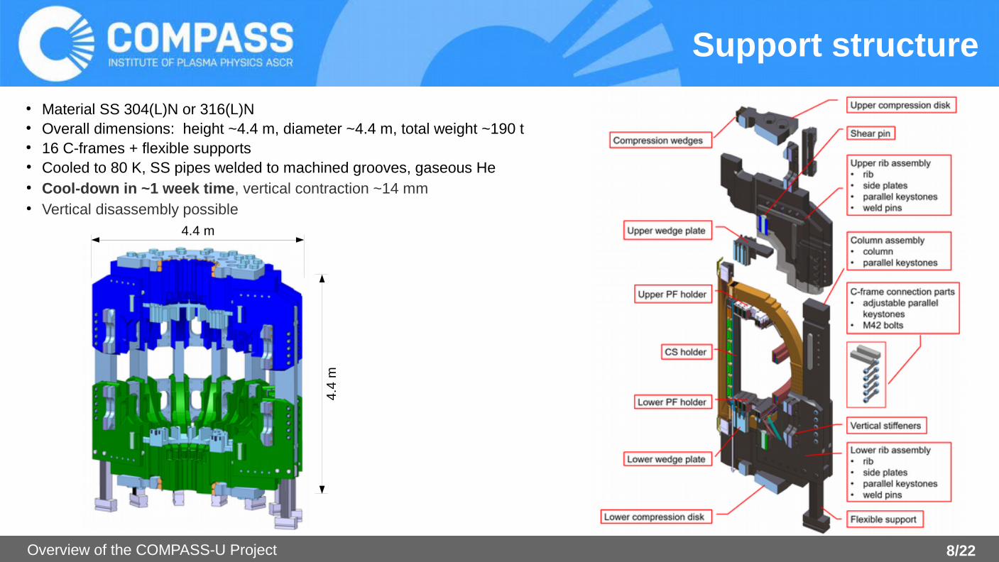
Support structure
● Material SS 304(L)N or 316(L)N● Overall dimensions: height ~4.4 m, diameter ~4.4 m, total weight ~190 t● 16 C-frames + flexible supports● Cooled to 80 K, SS pipes welded to machined grooves, gaseous He● Cool-down in ~1 week time, vertical contraction ~14 mm● Vertical disassembly possible
4.4
m
4.4 m
9/NOverview of the COMPASS-U Project 9/22
Support structure
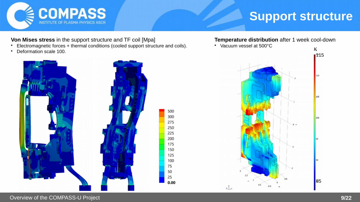
Von Mises stress in the support structure and TF coil [Mpa]• Electromagnetic forces + thermal conditions (cooled support structure and coils).• Deformation scale 100.
Temperature distribution after 1 week cool-down• Vacuum vessel at 500°C
85
115K
10/NOverview of the COMPASS-U Project 10/22
Toroidal field coils
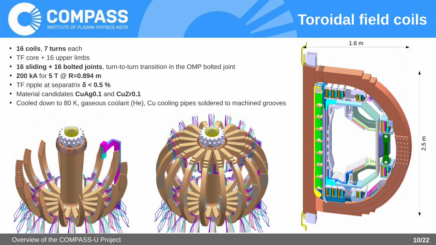
● 16 coils, 7 turns each● TF core + 16 upper limbs● 16 sliding + 16 bolted joints, turn-to-turn transition in the OMP bolted joint● 200 kA for 5 T @ R=0.894 m● TF ripple at separatrix δ < 0.5 %● Material candidates CuAg0.1 and CuZr0.1● Cooled down to 80 K, gaseous coolant (He), Cu cooling pipes soldered to machined grooves
2.5
m
1.6 m
11/NOverview of the COMPASS-U Project 11/22
Toroidal field coilsjoints
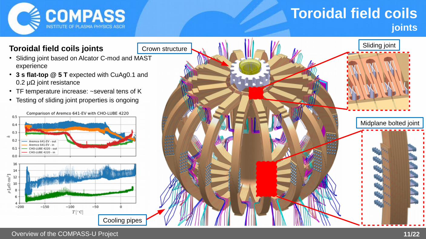
Toroidal field coils joints● Sliding joint based on Alcator C-mod and MAST
experience● 3 s flat-top @ 5 T expected with CuAg0.1 and
0.2 μΩ joint resistance● TF temperature increase: ~several tens of K● Testing of sliding joint properties is ongoing
Crown structure Sliding joint
Midplane bolted joint
Cooling pipes

12/NOverview of the COMPASS-U Project 12/22
Poloidal field coils
● 8 identical CS coils, 4+4 PF coils● 1 power supply per pair of CS coils => 14 PS in total.● Hollow conductor - material CuAg0.1 (C10700), half or full hard● Cooling down to 80 K by gaseous coolant (He, H2)● Conductor Insulation: 1 mm S2 glass tape + kapton● Inter-layer insulation: 0.6 mm S2 glass tape● Ground insulation: 3 mm S2 glass tape● Vacuum pressure impregnation using epoxy resin
name, qty.
Current range [kA]
Conductorw x h[mm]
D [m] turnswinding length
[m]
cooling segments
8x CS ± 50 24 x 21 0.8 29 90 1
2x PF1a ± 25 15 x 15 1.2 32 120 2
2x PF1b ± 25 15 x 15 1.3 32 137 2
2x PF2 ± 25 15 x 15 1.5 32 155 2
2x PF3 ± 25 15 x 15 2.1 36 233 3
2x PF4 ± 30 17 x 20 2.9 40 360 5
CS1U
CS2U
CS3U
CS4U
CS4L
CS3L
CS2L
CS1L
PF
1aU
PF
2U
PF
3U
PF
4L
PF
1bU
PF
1aL
PF
2L
PF
3L
PF
1bL
PF
4U

13/NOverview of the COMPASS-U Project 13/22
Central solenoid pre-load● CS is placed inside of inner and outer tie tubes (Nitronic)● Outer tie tube is fixed to the lower TF wedge plate● 20 stacks of heavy duty Belleville washers● ~several MN pre-load, ~1 cm working range
Poloidal field coilsCentral solenoid
Outer tie tube
Inner tie tube
CS feeders
CS pre-load mechanism

14/NOverview of the COMPASS-U Project 14/22
Vacuum vessel
● Material: Inconel 625● 23 mm thick inner tube, 35 mm top, bottom and 30 mm LFS parts● total weight: ~9 t (including PSP)● 8 flexible Inconel 625 supports from bottom – connected to the lower
compression disk of the support structure
Flexible plate support of VV
PSP support
Passive Stabilising Plates (PSP)
Main vessel
R1325
R538
2 types of midplane ports, 3 types of divertor ports

15/NOverview of the COMPASS-U Project 15/22
Vacuum vesselheating
● Heating of VV up to 500 °C in ~24 h => heating power~40 kW● Removal of deposited energy from plasma discharge (max. 40 MJ) in 20 min. => cooling power ~33 kW● Inconel 625 pipes welded on inside of VV, OD 16 mm, 2 mm wall● Gaseous medium (He or CO
2 )
● PFC heated mainly by radiation● 20 mm MLI thermal insulation at the outer surface
Temperature distribution at the vacuum vessel and port extensions. Von Mises stress in the vacuum vessel and PSP. Vacuum vessel heating pipe routing.
Static Dynamic
MPa
16/NOverview of the COMPASS-U Project 16/22
Plasma Facing Components
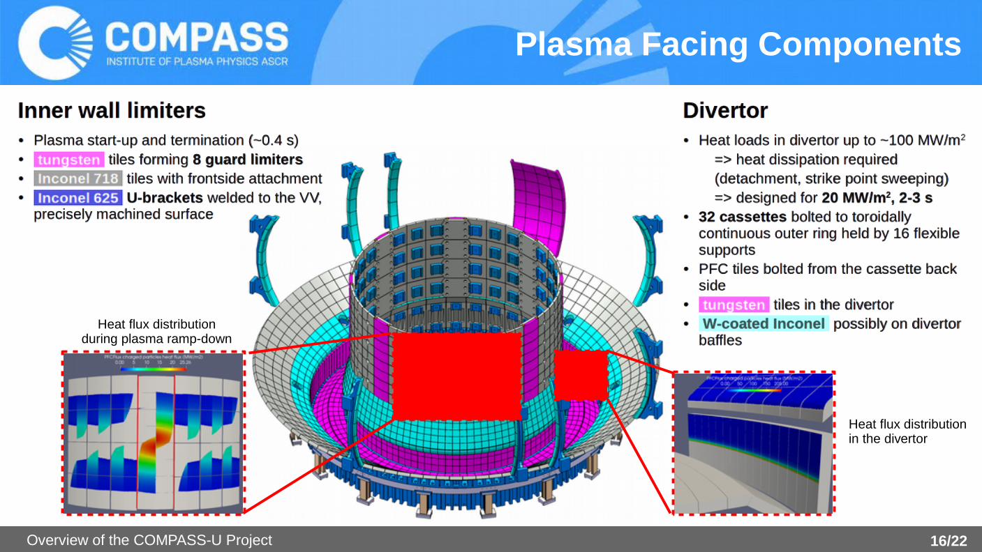
Inner wall limiters● Plasma start-up and termination (~0.4 s)● tungsten tiles forming 8 guard limiters● Inconel 718 tiles with frontside attachment● Inconel 625 U-brackets welded to the VV,
precisely machined surface
Divertor● Heat loads in divertor up to ~100 MW/m2
=> heat dissipation required(detachment, strike point sweeping)=> designed for 20 MW/m2, 2-3 s
● 32 cassettes bolted to toroidally continuous outer ring held by 16 flexible supports
● PFC tiles bolted from the cassette back side
● tungsten tiles in the divertor● W-coated Inconel possibly on divertor
bafflesHeat flux distribution
during plasma ramp-down
Heat flux distribution in the divertor
17/NOverview of the COMPASS-U Project 17/22
115 K
85 K
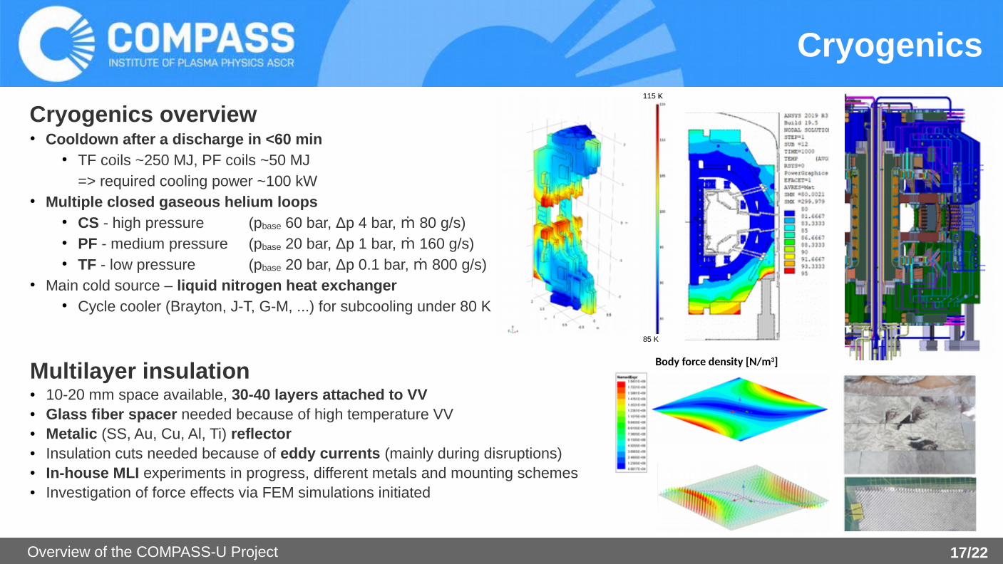
Cryogenics
Cryogenics overview● Cooldown after a discharge in <60 min
● TF coils ~250 MJ, PF coils ~50 MJ=> required cooling power ~100 kW
● Multiple closed gaseous helium loops● CS - high pressure (pbase 60 bar, Δp 4 bar, ṁ 80 g/s)● PF - medium pressure (pbase 20 bar, Δp 1 bar, ṁ 160 g/s)● TF - low pressure (pbase 20 bar, Δp 0.1 bar, ṁ 800 g/s)
● Main cold source – liquid nitrogen heat exchanger● Cycle cooler (Brayton, J-T, G-M, ...) for subcooling under 80 K
Multilayer insulation● 10-20 mm space available, 30-40 layers attached to VV● Glass fiber spacer needed because of high temperature VV● Metalic (SS, Au, Cu, Al, Ti) reflector● Insulation cuts needed because of eddy currents (mainly during disruptions)● In-house MLI experiments in progress, different metals and mounting schemes● Investigation of force effects via FEM simulations initiated
Body force density [N/m3]
18/NOverview of the COMPASS-U Project 18/22
NBI
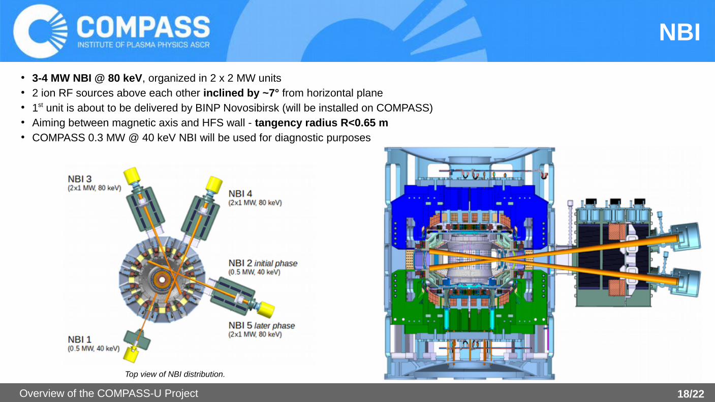
● 3-4 MW NBI @ 80 keV, organized in 2 x 2 MW units● 2 ion RF sources above each other inclined by ~7° from horizontal plane● 1st unit is about to be delivered by BINP Novosibirsk (will be installed on COMPASS)● Aiming between magnetic axis and HFS wall - tangency radius R<0.65 m● COMPASS 0.3 MW @ 40 keV NBI will be used for diagnostic purposes
Top view of NBI distribution.

19/NOverview of the COMPASS-U Project 19/22
ECRH
ECRH for different COMPASS-U scenarios Deposition on-axis is achieved for B
t 1-2.5 and 5 T
Toroidal steering needed for Bt 3-4 T
● Simulations in TORBEAM + ASTRA ongoing
Components specification● Gyrotrons: dual freq. 105-140 GHz, 1MW, 3-5s pulse length● Waveguides: 63.5 mm diameter, total length < ~30 m● Launchers: large equatorial port, steering mirrors
scenario Bt [T] n
co [m-3]
Operation mode f [GHz]
2 1.25 0.9x1020 X3 105
3 2.5 1.2x1020 X2 140
12 3.4 1.4x10²⁰ O1, toroidal steering 105
4 4.3 2.4x10²⁰ O1, toroidal steering 140
6 5 2.4x10²⁰ O1 140
Scenario 12.4 (3.4 T), 105 GHz, O-modeOptimal injec. 20°, full abs. at <0.3⍴

20/NOverview of the COMPASS-U Project 20/22
Power supply system
Schematic overview of the power supply system.
Power Supply System● Existing flywheel generators (50 MVA, 50 MJ each)● Two new flywheel generators (106 MVA, 195 MJ each)● PF coils:
● 85 MW, 90 MJ from flywheel● IGBT H-bridges
● TF coils:● 140 MW, 340 MJ● thyristor converters
● Auxiliary heating + reserve: 38 MW, 60 MJ● In total: 263 MW, 490 MJ
Status● FDR completed in February 2019● Contract signed in February 2020

21/NOverview of the COMPASS-U Project 21/22
Neutronics
● The majority of ionizing radiation will come from beam-target produced neutrons during NBI operation.● The expected neutron rate 1×10¹⁴ to 1.8×10¹⁵ neutrons/s (4 MW NBI)
=> yearly production of 3×10¹⁸ neutrons for the expected scenario distribution.● Monte Carlo simulations were carried out with the MCNP code to calculate both the neutron and gamma
fields inside the experimental hall (IFJ PAN, Poland)

22/NOverview of the COMPASS-U Project 22/22
Summary & Outlook
https://youtu.be/oGfg0A5EsSE


![[Solutions] Introduction to Plasma Physics and Controlled Fusion Plasma Physics](https://img.dokumen.tips/doc/110x75/55cf9d44550346d033ace210/solutions-introduction-to-plasma-physics-and-controlled-fusion-plasma-physics.jpg)