Embed Size (px)
Citation preview

Overview of advanced cathodes for High Brightness Beams
L. Cultrera(INFN-LNF)
Workshop on the physics and application of high brightness electron beamsMaui, Hawaii
November 16-19, 2009
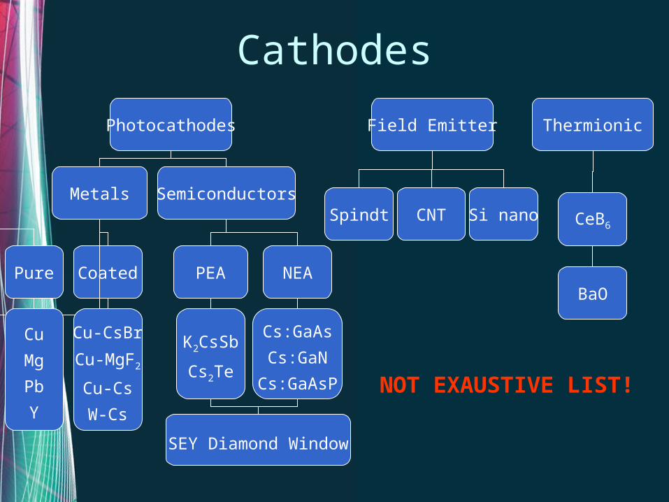
Cathodes
Photocathodes Field Emitter Thermionic
Metals Semiconductors
Pure Coated PEA NEA
Cu
Mg
Pb
Y
Cu-CsBr
Cu-MgF2
Cu-Cs
W-Cs
K2CsSb
Cs2Te
Cs:GaAs
Cs:GaN
Cs:GaAsP
Spindt Si nanoCNT
NOT EXAUSTIVE LIST!
CeB6
BaO
SEY Diamond Window

Brigthness of an electron beam
• Brightness is limited by:– thermal emittance
• Emission size• Transverse momentum distribution
– achievable current• Photocathode => QE and laser damage• Field emitter => arcing and Joule effect• Thermoionic => Electric field
ynxn
InB ,,
2
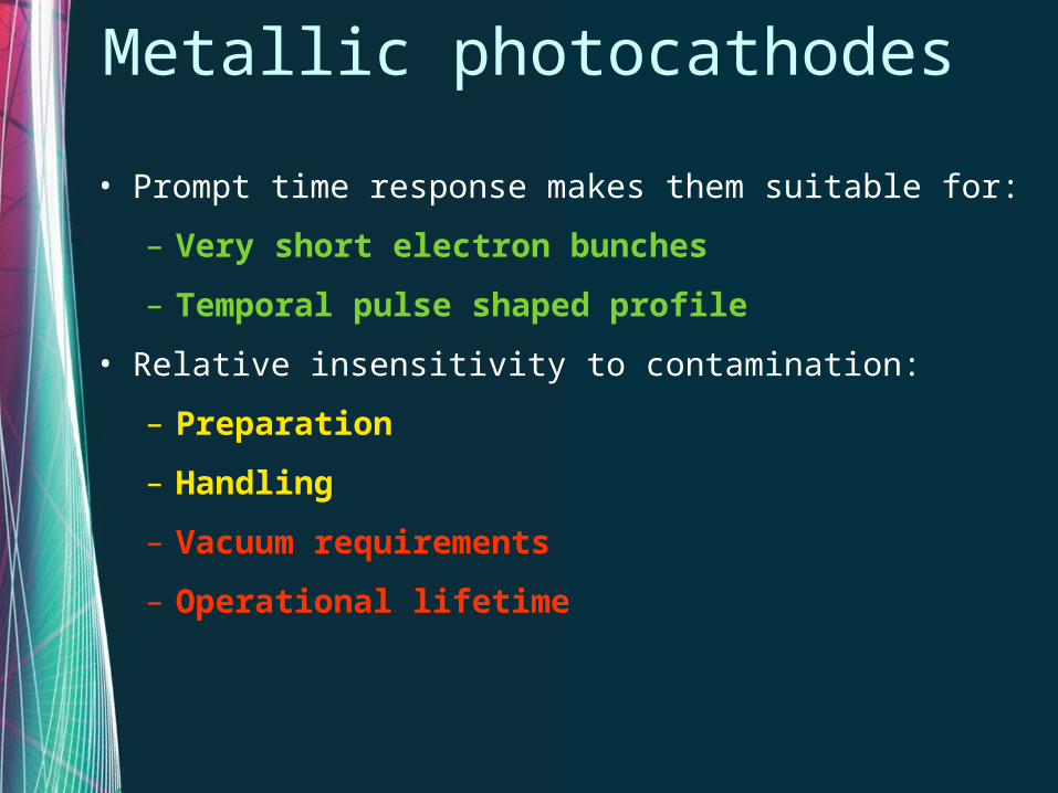
Metallic photocathodes
• Prompt time response makes them suitable for:
– Very short electron bunches
– Temporal pulse shaped profile
• Relative insensitivity to contamination:
– Preparation
– Handling
– Vacuum requirements
– Operational lifetime
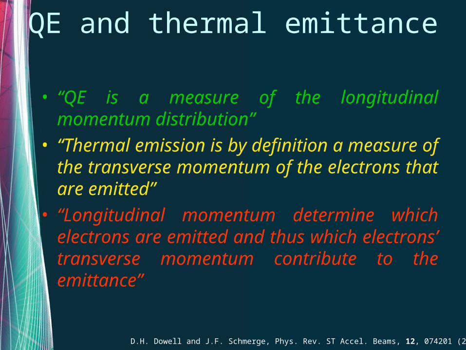
QE and thermal emittance
• “QE is a measure of the longitudinal momentum distribution”
• “Thermal emission is by definition a measure of the transverse momentum of the electrons that are emitted”
• “Longitudinal momentum determine which electrons are emitted and thus which electrons’ transverse momentum contribute to the emittance”
D.H. Dowell and J.F. Schmerge, Phys. Rev. ST Accel. Beams, 12, 074201 (2009)

QE and thermal emittance
effFeff
eff
ee
opt E
RQE
81
12
D.H. Dowell and J.F. Schmerge, Phys. Rev. ST Accel. Beams, 12, 074201 (2009)
23mc
v effxth
Generally speaking to get higher QE from metallic photocathode it should be accepted that this will give higher thermal emittance.

Metallic photocathode: lifetimeDespite their claimed contamination
insensivity even in UHV (10-9 mbar range) low work function metals as Mg, Y but also the most and inert Cu may suffer from the contamination due to chemical species present in residual gases (H2, CO, CO2, H2O).
Background Pressuresw/o RF ~ 5x10⁻¹⁰
mbarwith RF ~ 2x10⁻⁹
mbarCu
Y Mg

• Wide band gap thin film coatings are giving interesting and in some way unexpected results
Improving lifetime
Accurate choice of the coating material to be transparent to the laser wavelength. The thickness may be designed to create an antireflecting coating at the cathode surface.

Metals with CsBr coating• Transmission @ 257 nm• Photoemission arises from
intraband states• Electrons injected through
the metal insulator junction sustain the emission
• Reflection @ 257 nm• 50 times higher QE• No strong degradation of
QE due to air exposre
Z. Liu et al., Appl. Phys. Lett., 89, 111114 (2006)J. Maldonado et al., Phys. Rev. ST Accel. Beams, 11, 060702 (2008)
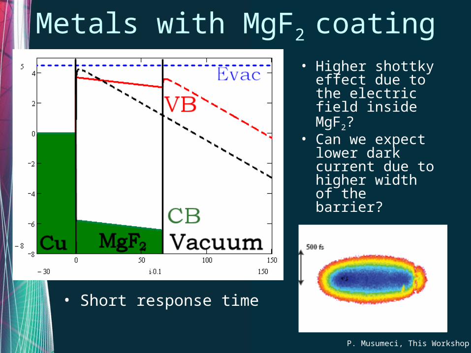
Metals with MgF2 coating
P. Musumeci, This Workshop
• Short response time
• Higher shottky effect due to the electric field inside MgF2?
• Can we expect lower dark current due to higher width of the barrier?

SPARC and SPARX photocathode R&D
• Cu and Mg needs UV photons (266 nm, 3rd
harmonic Ti:Sa) while Y should emits electrons in visible range (400 nm, 2nd
harmonic Ti:Sa)Yttrium emission curve @ 406 nm after laser
cleaning
QE ~ 3.4x10⁻⁵
1 nC should require about 100 J laser pulses @ 406 nm

Yttrium Lifetime
Time (s)
QE
Pbg=10-9 mbarE = 1.7 MV/m= 406 nm
May be improved with MgF2 coating?
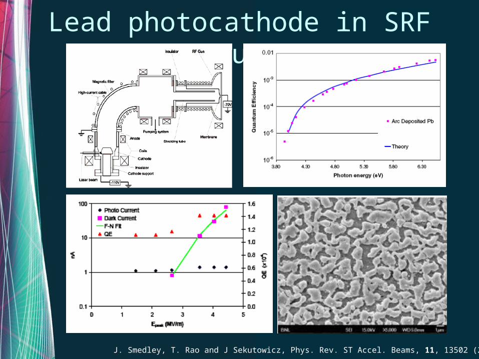
Lead photocathode in SRF gun
J. Smedley, T. Rao and J Sekutowicz, Phys. Rev. ST Accel. Beams, 11, 13502 (2008)
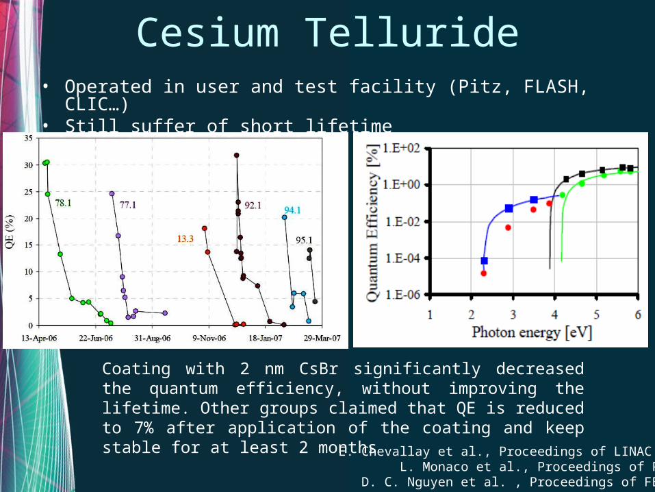
Cesium Telluride• Operated in user and test facility (Pitz, FLASH, CLIC…)• Still suffer of short lifetime
Coating with 2 nm CsBr significantly decreased the quantum efficiency, without improving the lifetime. Other groups claimed that QE is reduced to 7% after application of the coating and keep stable for at least 2 months
E. Chevallay et al., Proceedings of LINAC 2000L. Monaco et al., Proceedings of PAC07
D. C. Nguyen et al. , Proceedings of FEL 98

KCsSb with protective coating
• Loosing efficiency by means of protective layer increases the stability versus reactive gases
E. Shefer et al, Nucl. Instr. Met. A, 433, 502 (1999)
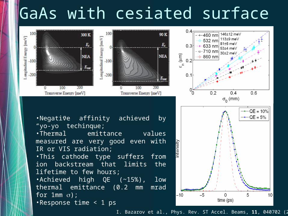
GaAs with cesiated surface
•Negative affinity achieved by “yo-yo” techinque;•Thermal emittance values measured are very good even with IR or VIS radiation;•This cathode type suffers from ion backstream that limits the lifetime to few hours;•Achieved high QE (~15%), low thermal emittance (0.2 mm mrad for 1mm );•Response time < 1 ps
I. Bazarov et al., Phys. Rev. ST Accel. Beams, 11, 040702 (2008)
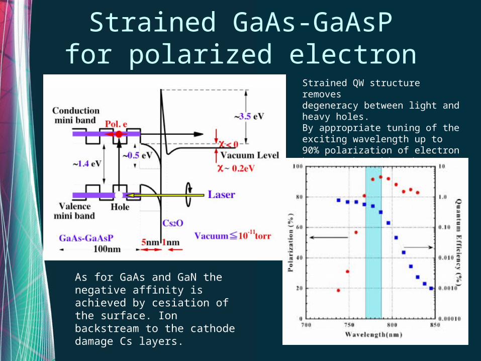
Strained GaAs-GaAsPfor polarized electron beam
Strained QW structure removesdegeneracy between light and heavy holes.By appropriate tuning of the exciting wavelength up to 90% polarization of electron beam can be achieved
As for GaAs and GaN the negative affinity is achieved by cesiation of the surface. Ion backstream to the cathode damage Cs layers.
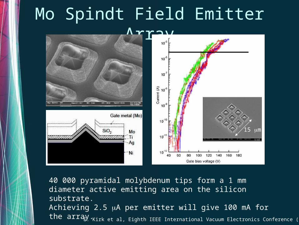
Mo Spindt Field Emitter Array
E. Kirk et al, Eighth IEEE International Vacuum Electronics Conference (2007)
15 m
40 000 pyramidal molybdenum tips form a 1 mm diameter active emitting area on the silicon substrate.Achieving 2.5 A per emitter will give 100 mA for the array.

Mo Spindt Field Emitter Array
S. C. Leemann, A. Streun, and A. F. Wrulich, Phys. Rev. ST Accel. Beams, 10, 071302 (2007)
50000 conical molybdenum tips form a 1 mm diameter active emitting area on the silicon substrate.Achieved 2 mA with DC pulses of 100 ns and 40 kV.
Beamlets pinhole maskBeamlet single slit
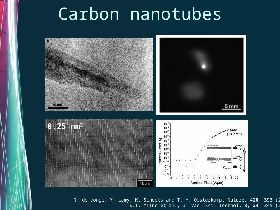
Carbon nanotubes
N. de Jonge, Y. Lamy, K. Schoots and T. H. Oosterkamp, Nature, 420, 393 (2002)W.I. Milne et al., J. Vac. Sci. Technol. B, 24, 345 (2006)
0.25 mm2

Photo field assisted cathode
L. Hudansky et al., Nanotechonology, 19, 105201 (2008)R. Ganter et al., Phys. Rev. Letter, 100, 064801 (2008)
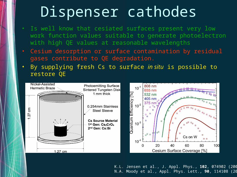
Dispenser cathodes• Is well know that cesiated surfaces present very low work function
values suitable to generate photoelectron with high QE values at reasonable wavelengths
• Cesium desorption or surface contamination by residual gases contribute to QE degradation.
• By supplying fresh Cs to surface in situ is possible to restore QE
K.L. Jensen et al., J. Appl. Phys., 102, 074902 (2007)N.A. Moody et al., Appl. Phys. Lett., 90, 114108 (2007)

Dispenser rejuvenation
J. Montgomery et al., Proc of AAC 13° Workshop, 599 (2009)N.A. Moody et al., Proc. FEL 2006, 748 (2008)
External Cs source on Silver illuminated with 375 nm laser
Subsurface Cs source on W cathode
“Two modes of cathode operation were demonstrated: periodic and continuous rejuvenation. The 1/e effective (continuous duty cycle) lifetime in this mode was an astounding 47 days.”
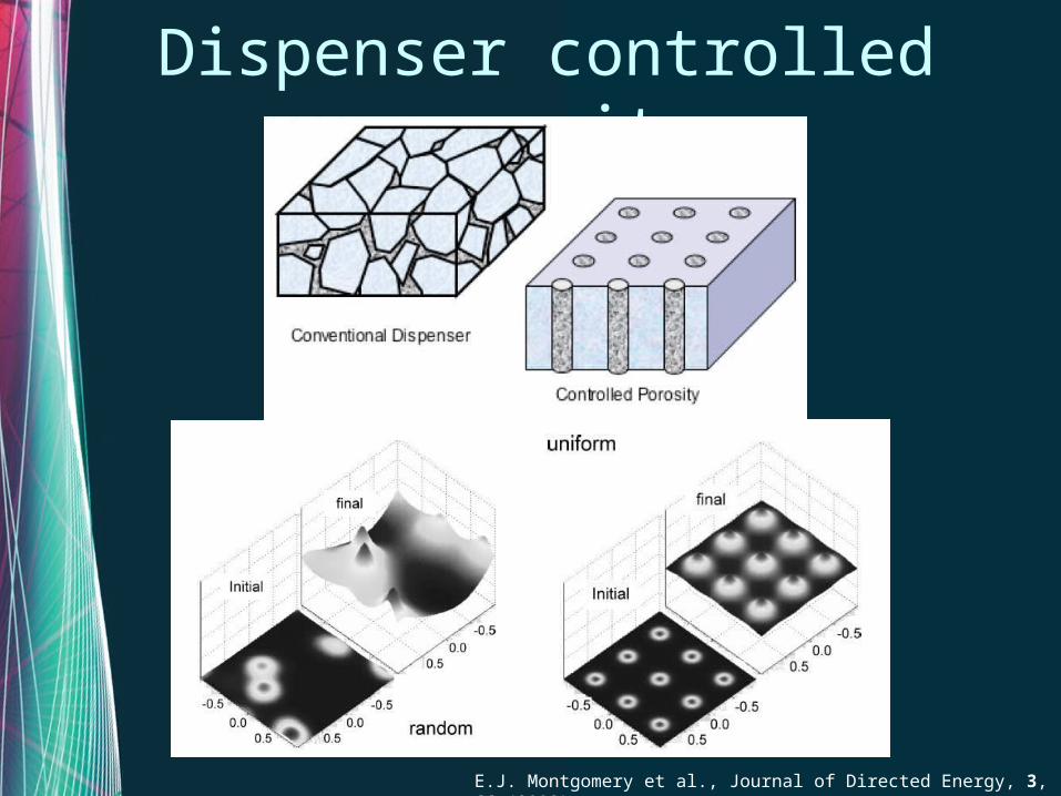
Dispenser controlled porosity
E.J. Montgomery et al., Journal of Directed Energy, 3, 66 (2008)
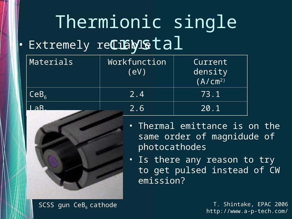
Thermionic single crystal• Extremely reliable
Materials Workfunction (eV)
Current density (A/cm2)
CeB6 2.4 73.1
LaB6 2.6 20.1
• Thermal emittance is on the same order of magnidude of photocathodes
• Is there any reason to try to get pulsed instead of CW emission?
T. Shintake, EPAC 2006http://www.a-p-tech.com/
SCSS gun CeB6 cathode
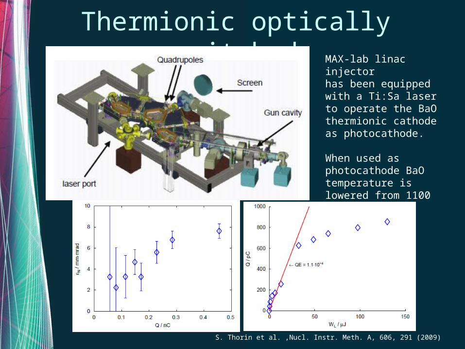
Thermionic optically switched
S. Thorin et al. ,Nucl. Instr. Meth. A, 606, 291 (2009)
MAX-lab linac injectorhas been equipped with a Ti:Sa laser to operate the BaO thermionic cathode as photocathode.
When used as photocathode BaO temperature is lowered from 1100 to 700 °C
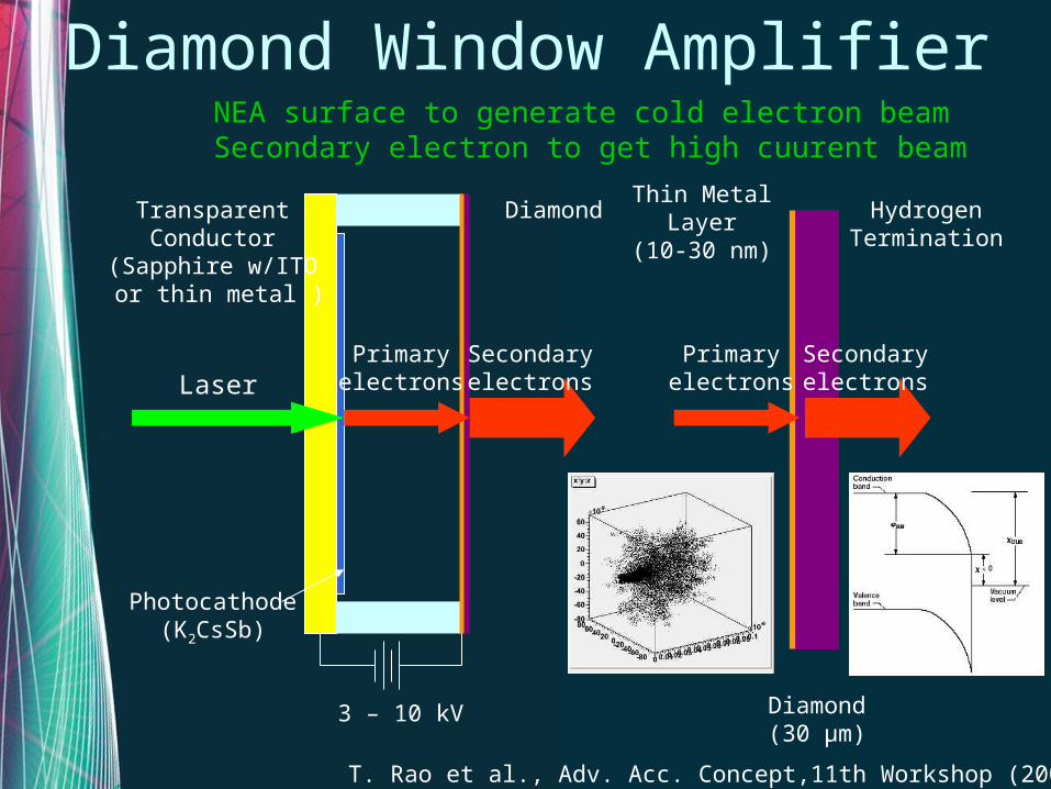
Diamond Window Amplifier
3 – 10 kV
TransparentConductor
(Sapphire w/ITO or thin metal )
Photocathode(K2CsSb)
LaserPrimary
electronsSecondaryelectrons
DiamondThin Metal
Layer(10-30 nm)
Diamond(30 μm)
HydrogenTermination
Primaryelectrons
Secondaryelectrons
NEA surface to generate cold electron beam Secondary electron to get high cuurent beam
T. Rao et al., Adv. Acc. Concept,11th Workshop (2004)
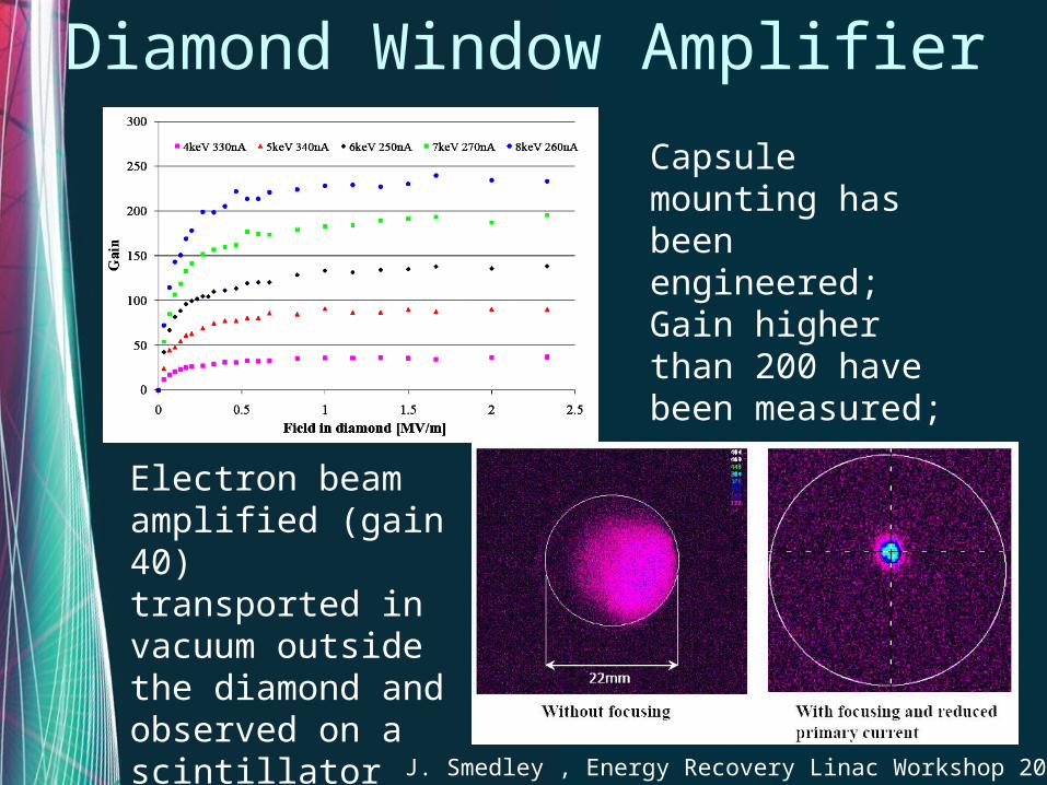
Diamond Window Amplifier
Capsule mounting has been engineered;Gain higher than 200 have been measured;
Electron beam amplified (gain 40) transported in vacuum outside the diamond and observed on a scintillator screen
J. Smedley , Energy Recovery Linac Workshop 2009
Conclusion
• Still a lot of work to do:– Lifetime and stability of emission
• Photocathodes• Field emitter
– New ideas in making hybrids emitter combining advantages of different emission mechanisms

Thank you for the attention!