Embed Size (px)
Citation preview

86 PHILIPS TECHNICAL REVIEW VOLUME 29
Oversized rectangular waveguide componentsfor millimetre waves
H. J. Butterweck and F. C. de Ronde
Since microwaves first came into practical use, the hol/ow pipe, usually ofrectangular cross-section, has been the standard means for transmission of the waves. In the conventional use ofthis waveguide the waves can travel in a single precisely defined pattern - a very valuableproperty of the guide for many applications. IJ, however, the same techniques are used inthe millimetre and submillimetre wavebands, power loss in the guide becomes a very severeproblem and the components become prohibitively small. These have been two of the chiefreasons for the development of other types of transmission lines. .
In the "oversized waveguide" the losses are much lower than in the standard guide, whilethe advantage of propagation in a well-defined pattern can be maintained by proper "mode
. control". The size of the guide can be chosen in a convenient range. Another important ad-vantage is that very broad-band components can be made.
Introduetion
At microwave frequencies electromagnetic waves canpropagate along several types oftransmission line.Thesecan be divided into two classes. In the first class theelectromagnetic field extends to infinity in the directiontransverse to the axis of propagation; the correspondingstructures are usually said to be "open". In the secondclass the electromagnetic field has only a finite trans-verse extension. Since the boundaries are imposed bymetallic screening, this class is said to be "shielded"or "closed".Well-known transmission lines such as the dielectric
line [ll, the image line [2l, the H-guide [3l and themicrowave beam [4l, belong to the firstclass. The shieldedstructures of the second class include hollow pipesand pipes containing one or more inner conductors.The rectangular waveguide and the coaxialline are typ-ical representatives of this class.In the millimetre-wave region, to which we shall con-
fine ourselves, both classes of structures have theirspecific fields of application and both have their specialadvantages [5l. In this article we shall be concernedwith the closed structures. Let us begin by noting someof their advantages. First, the shielding prevents radia-tion. and makes the device insensitive to parasitic elec-tromagnetic fields; there is no coupling even betweenclosely spaced guides. Secondly, the shielding part ofthe structure gives sufficient rigidity without requiring
Dr. H. J. Butterweck.formerly with Philips Research Laboratories,Eindhoven, is now Professor of Electrical Engineering at theTechnical University of Eindhoven, Netherlands; Ir. F. C. de Rondeis with Philips Research Laboratories, Eindhoven.
additional support, and alignment is quite easy. Finally,many almost ideal components (bends, directionalcouplers, etc.) can be produced: this is not so with theopen structures, where diffraction phenomena mayeasily giverise to unpredictable deviations from the idealbehaviour.
A traditional closed microwave structure is designedto operate in a single mode: waves of a single defi-nite pattern only can be propagated. For this to betrue the structure must be of "standard size", i.e. thecross-sectional dimensions must not exceed certain criti-cal values which are of the order of magnitude of thewavelength used. For millimetre waves in particular,if a cross-section is to be of standard size it must besmaller than a few millimetres across. Coaxial trans-mission lines of this- size are extremely lossy andtherefore not very suitable for millimetre-wave appli-cations. On the other hand, standard-size rectangularwaveguide components for wavelengths as short as2 mm have been developed and are in current use [6l.
If, at a given frequency, the cross-sectional dimen-sions of a guide do exceed the critical value referred toabove, transmission is possible in several modes. Aswe shall explain more fully below, this will in general,lead to an unstable electromagnetic field pattern,that is to say, the pattern may vary erratically alongthe guide. If, however, it is possible to prevent theexcitation of the higher-order modes, such "oversized"transmission lines have several advantages over stan-dard-size lines. To mention a few: the attenuation can beconsiderably lower, braad band components can be
1968, No. 3/4 OVERSIZED WAVEGUlDE FOR mm-WAVES 87
designed, and, particularly in the millimetre and sub-millimetre range, manufacture can be easier. The speci-fic problems associated with <oversized transmissionlines will be the subject of the present article.
Transmission lines of three main types of cross-section are usually considered. These are: the rectangu-lar waveguide, the circular waveguide, and the coaxialline. The latter is of no interest here, as the design ofcomponents not exciting higher-order modes proves tobe very difficult. The oversized circular waveguide hasbecome very promising, particularly for long-distancetransmission [7]. For laboratory applications, however,the rectangular form offers certain advantages.
The present article is mainly about the rectangulartype of oversized waveguide, which has already attractedsome interest [8]; a brief comparison between the cir-cular type and the rectangular type will be given at theend. After a general discussion of the mode spectrum ofthe rectangular waveguide, we pay special attention tothe measurement and control of higher-order modes.Several components which have been developed inour laboratory will be described in detail. In particular,we discuss mode filters, tapers, bends, directionalcouplers, and variable attenuators, phase shifters, andimpedances. Finally various applications are enu-merated.
Most of our components have been designed for andtested in the 4-mm wave region, and have been builtusing standard 3-cm waveguide as a starting point.
Mode spectrum of the rectangular waveguide
To give an insight into the problems associated withhigher-order modes let us consider some fundamentalproperties of hollow waveguides [9]. Assuming that wehave a waveguide of constant cross-section, let us raisethe frequency (instead of taking increased dimensions ata given frequency, as above). To begin with no propa-gation of electromagnetic waves is possible at all belowa critical frequency, the cut-off frequency fcl. This cut-off frequency is a specific property of the cross-sectionunder consideration. For frequencies f slightly abovefCl the electromagnetic field propagates in a charac-teristic pattern, thefundamental mode ofthe waveguide.If the frequency is raised further, a second cut-off fre-quency fC2 is obtained, above which another mode witha different field pattern can be propagated. (For fC2the waveguide has the critical dimensions referred to inthe introduction.) Every waveguide has an infinitespectrum of such cut-off frequencies [a, fC2, fC3, ... ,so that for sufficiently high frequencies the energy canbe transmitted in a large number of modes simulta-neously. In most cases it turns out that the cut-offwavelength ACl corresponding to the first cut-off fre-quency j~l has the same order of magnitude as the di-
mensions of the cross-section (this wavelength is givenby ACl= clfcl, where c is the free-space velocity oflight). Thus any wave that can be propagated has afree-space wavelength A comparable to these dimen-sions or smaller.
A specific mode is propagated along the waveguidewithout change of the transverse field distribution. In alossless waveguide, the amplitude is constant. The phasevelocity Vi of the mode i, i.e. the velocity of propaga-tion of the field pattern, is given by:
(I) .
where ACi is the cut-off ~avelength of the mode. Thus,at a given frequency, the phase velocities are differentfor different modes. Therefore, if several modes areexcited, the transverse electromagnetic field distribu-tion varies along the guide owing to the continuouslyvarying phase differences between the individual modes.This unstable situation may occur if f> fC2, and ifthe frequency satisfies this condition the waveguide issaid to be overmoded or oversized. If the frequency liesbetweenfcl andfc2, the case which we shall referto asstandard-size operation, only the fundamental modeis present and the propagation is stable. If stable opera-tion is required in. oversized waveguide, special carehas to be taken to excite only one mode, which need notnecessarily be the fundamentalone. Such "modecontrol" will be discussed in detail in the next section.
We now apply these general considerations to thespecial case of a rectangular cross-section. Let a and
[1] G. SchuIten, Archiv elektr. Übertr. 14, 163-166, 1960; seealso: H, Severin and G. SchuIten, Surface-wave transmis-sion lines for microwave frequencies, Philips tech. Rev. 26,342-356, 1965.
[2] S, P. Schlesinger and D. D. King, IRE Trans. MTT-6,291-299, 1958. The image line is also discussed in the secondarticle in ref. [1].
[3] J. W. E, Griemsmann and L. Birenbaum, Proc. Symp. Milli-meter Waves, New York 1959,pub!. Polytech. Inst. Brooklyn1960, p. 543-562.
[4] T. Nakahara and N. Kurauchi, IEEE Trans. MTT-1S,66-71, 1967 (No. 2); A. G. van Nie, Philips Res. Repts. 19,378-394, 1964 and Nachr.techn. Z., edn. Comm. J. 6, 264-269, 1965.
[5] An extensive survey of several types of transmission linestudied in view of their application at millimetre and sub-millimetre wavelengths and paying special attention to
. losses has been made by D. J. Kroon and J. M. van Nieuw-land of this laboratory. This survey is published in: D. H.Martin, Spectroscopie techniques for far infra-red, submilli-metre and millimetre waves, North-Holland Pub!. Co.,Amsterdam 1967, Chap. 7: Techniques of propagation atmillimetre and submillimetre wavelengths, p. 308-380.
[6] C. W. van Es, M. Gevers and F. C. de Ronde, Waveguideequipment for 2 mm microwaves, Philips tech. Rev. 22,131-125 andI81-189, 1960/61.
[7] S. E. Miller, Bell Syst. tech. J. 33, 1209-1265, 1954.[8] J. J. Taub, H. J. Hindin, 0, F. Hinckelmann and M. L.
Wright, IEEE Trans. MTT-ll, 338-345, 1963.[0] For extensive theoretical treatments of th is subject the reader
is referred to standard textbooks on waveguide theory. Anintroduetion is given in: W. Opechowski, Electromagneticwaves in waveguides, Philips tech. Rev. 10, 13-25 and 46-54,1948/49.<

88 PHILlPS TECHNICAL REVIEW VOLUME29
Fig. 2. Field pattern of thefundamental mode and somehigher-order modes in .rectan-gular waveguide. The longi-tudinal cross-section is shownabove, and the transversecross-section below. The elec-tric field lines are shown solidand the magnetic field linesdashed. It should be notedthat many of the lines drawnin the cross-sectional planesare not the actual field lines,but projections of the fieldlineson these planes. In the longi-tudinal cross-sections the di-rections indicated (arrows) arethose of the lines near the topof the guide, and in the trans-verse cross-section the direc-tions are those of the lines near the section A-A (as indicated in the first drawing). These directions correspond to the direction ofpropagation indicated between the first two drawings. The various modes are drawn in such a way that they have the sameguide wavelength Àg= vII! (the length of the longitudinal section drawn is ~Àg); this implies that, if the Àcl's differ, the frequen-cies will be different (cf. eq. 1).
A
1
b be the width and the height of the rectangle, res-pectively, where a> b. The first cut-off wavelength isthen given by:
ÁCI = 2a.
The field pattern of the fundamental mode, often re-ferred to as the HlO mode, is shown infig. 1. The elec-tric field lines E are parallel to the shorter side of thewaveguide while the magnetic field lines H lie in planesperpendicular to the electric field. The cut-off wave-lengths Ácmn of the higher-order modes are given by:
(2/Ácmn)2 = (m/a)2 + (n/b)2.
Fig. 1. Field pattern of the HIO mode in rectangular waveguide.
(2)
this type are generally called H modes. Thus we have anH2o mode, an H30 mode, an HOI mode, etc. If neitherm nor n is zero, two different field patterns are possiblewhich have the same cut-off wavelength Ácmn. Thefirst, known as Hmn, has again a vanishing electric fieldcomponent Ez, but a non-vanishing Hz; the second,known as Emn, has a vanishing magnetic field compo-nent Hz, but a non-vanishing Ez. The indices m and nare equal to the number of half periods of the wavepattern along the width a and the height b respectively.
Fig. 3 is an illustration of how the field pattern of thefundamental mode in an oversized waveguide is elon-gated in the transverse direction and compressed in thelongitudinal direction, compared with the pattern instandard-size guide. When a guide is highly oversizedthe pattern is close to that of a transverse electromagne-tic wave.
(3)
This expression yields the complete mode spectrum: an CIllIIl:I Ibinfinite set of modes, each characterized by two mode ~numbers m and n, one of which, but not both, may bezero.In fig. 2 the field patterns of the fundamental mode
and some higher-order modes of the rectangularwaveguide are shown. If m = ° or n = 0, then only themagnetic field has an axial component Hz; the axialcomponent of the electric field Ez vanishes. Modes of
II .0'=50
Fig. 3. The field pattern of the fundamental mode HlO at a givenfree-space wavelength À in a standard-size guide (the width a issmaller than À) and in a guide of width a' = 5a which is over-sized if 5a > À (cf. eq. 3). Oversizing has been obtained hereby increasing the width; sufficient increase of the height alonewould also give oversizing: in practical oversized waveguideboth dimensions are usually considerably larger than in thestandard-size guide.

1968, No. 3/4 OVERSIZED WAVEGUIDE FOR mm-WAVES
Eq. (3) yields the cut-off frequencies fcmn = C/Acmnfor any combination of indicesm and n. The mode spec-trum fcl, fC2, fc3 ... , arranged in order of increasingcut-off frequencies, depends upon a and b. The ratioalb determines the higher cut-offfrequencies relative tofc1. Mode spectra of this type are shown in fig. 4 forthe two values alb = 22.86/10.16= 2.25 and alb =22.86/1.55 = 14.8. The first case corresponds to stan-dard 3-cm waveguide (inner dimensions 0.9" X 0.4 ",i.e. 22.86 X 10.16mm), the second to a flat waveguide,with the same width as 3-cm waveguide but heightequal to that of 4-mm waveguide. For both configura-
20
I 11011
10I
5041 1
1 22
o~f 11I I I30b
I I
20I I I 11
./mO150
tions the ratio fC2/fc1, which determines the frequencyband of stable HlO mode transmission, is equal to 2.It is easy to show that this is the case wheneveralb ~ 2. If this condition is met the rectangularwaveguide, for standard-size operation, can be usedtheoretically over a frequency range of an octave.For practical purposes, however, only part of this bandis useful: in the vicinity oî f«: the losses ofthe HlO modebecome very high, and in the vicinity of fC2 the nexthigher-order mode H2o is almost propagating, whichmeans that this mode, if excited by an obstacle, diesaway very slowly. The frequency ratio fmax/fmin of the
61
90 91
140 141 14)130 131 !~.2
120 121 12·110 111 112
100 101 10290 91 92
80 81 8270 71 j60 61
50 5140 41
30
I ~I20
I10 II
_ma11p_m1102-m2
_m3
64 _m4
11 r h ~ 111 ~nJII III I1 =t~4'0 50 6b 70 GHz
/m1151
;1m2152
.....3n
.....2n
.....Tn--On
,I II~11,11111 ~ ~ 11111200 GHz
I I I I I Ililil! IIII III I III I II III II 11 III I1 III 60b 20 , 4'0 8'0 ' TOa ' 120 i 120 ' 160 i tdo
Fig. 4. Mode spectrum of standard 3-cm waveguide (upper diagram; alb = 2.25) and spectrumof a flat waveguide with the same width as 3-cm waveguide but height equal to that of 4-mmwaveguide (lower diagram; ajb == 14.8). The spectra show the cut-off frequencies fcmn abovewhich the mode (m, 11) can propagate. The numbers m and 11 are indicated in the figure. For aspecific pair m.n, both *' 0, two modes exist: the Emn,mode and the Hm« mode, with thesame cut-off frequency. For m or 11 = 0 only the modes Hon and Hmo are possible; Eon. Emoand Hoo do not exist.
89

90 PHILIPS TECHNICAL REVIEW VOLUME29
band recommended for standard-size operation ofrectangular waveguides is only 1.6.
Mode, control
As mentioned above, special care has to be takfm if,in an oversized waveguide, a single mode is wanted.This is because, even when a single mode is launched atthe input, many modes will easily arise in a circuit:in each microwave component and even at each irregu-larity in a waveguide there will be mode conversion, i.e.if a wave of a certain mode is incident on the componentor at the irregularity, other modes are excited.
One may ask just why multimode operation is soundesirable. The answer is that in multimode operationa simple description of the electromagnetic waves in acircuit is no longer possible. Even in a simple piece ofoversized waveguide the transverse field distribution isnot well defined and varies along the guide. More gen-erally, if a component is considered as a black boxwith a number of waveguide arms, the reflection andtransmission coefficients of the wanted modes as wellas the conversion coefficients must be known for acomplete description of such a component. If there areseveral components in the circuit, the mathematicaldescription may soon become so unwieldy that inpractice the field distribution is unpredictable; on theother hand, measurements in such a circuit will notlead to definite conclusions about the characteristicsof a certain component.Ifthe conversion from the wanted mode to unwanted
modes is negligible, we can refer to single-mode orstable operation of a specific oversized waveguide cir-cuit. However, it should be emphasized that, even ifthecoefficients describing the conversion into the separate-components are very small, higher-order modes withsubstantial amplitudes may arise. This may occur forexampleifthe higher-order modes, excited at some irreg--ularity, are trapped between two tapers, as shown injig. 5. A taper (to be treated in the following section)gives a smooth transition between an oversized wave-guide and a standard-size waveguide. Since only thefundamental mode can propagate in the standard guide,a higher-order mode incident from the oversizedsection is totally reflected. Multiple reflections of thehigher-order modes may give rise to resonance ofthese modes. If the frequency of the source coincides,with one 'of the resonance frequencies, absorptiontakes place causing a considerable loss in the totaltransmitted power. This, when plotted as a functionof frequency (fig. 5), may exhibit a great number ofsuch resonance absorptions. The density of theseresonances increases with increasing degree' of over-. ,
sizing and increasing length of the trapped-mode'resonator. Furthermore, the larger the conversion
coefficient of the irregularity and the lower theattenuation per unit length of the resonating mode,the stronger the absorption. In the limiting case ofvanishing attenuation the transmission may even bezero [lOl, which corresponds to a total reflection of theincident wave.There are some special applications of oversized
waveguides where it would be very difficult to achievesingle-mode transmission, but multimode operationis however acceptable. For instance, if submiIIimetrewaves are transmitted through a standard centimetre-waveguide, this guide is oversized to a very highdegree, and in such a case it is extremely difficultto make an almost ideal taper and launch only asingle mode [11l. Nevertheless, such a guide may beuseful, if only for transferring power over normalla bor-atory distances with low attenuation. In this case theexistence of higher-order modes does not essentially af-fect the overall transmission, for if the waveguide islong enough the trapped-mode resonances are welldamped out.Such special cases apart, oversized waveguides will
usually be used in single-mode operation. This is almostinvariably so in measurement work. If, for instance,a bridge circuit has to be designed, the components,such as power dividers and directional couplers shouldbe substantially free from mode conversion, since theexcitation of higher-order modes may easily lead tounpredictable errors.
3
Q
Fig. 5. Trapped-mode resonances. Microwave power from aswept-frequency generator 1 with standard-size output is fedthrough a taper 2 into oversized waveguide 3 and by a secondtaper 4 into a broadband detector 5 in standard-size waveguide.The tapers are assumed to be free from mode conversion. Modeconversion will take place at any irregularity 6. A higher-ordermode will be reflected in the tapers and be trapped, givingresonance losses at certain frequencies, which can be determinedfrom the power-frequency plot on the oscilloscope 7. a) Lowmode conversion at 6; b) high fuq,de conversion; c) the densityof resonances increases if the length-of the oversized waveguide3 or its degree of oversizing is increased.-,

1968, Np. 3/4 OVERSIZED WAVEGUIDE FOR mm-WAVES 91
Some time ago, we began an investigation in thislaboratory to find out how to design componentswith low mode conversion. For this work, we neededequipment for measuring the conversion coefficients.An essential element of such equipment is the modetransducer, several types of which are described below.If the components to be developed do not satisfy cer-tain requirements for mode purity, this can be improvedby mode filters, which will be described later. The meas-urements to test the components that had been devel-oped were all made with the aid of a swept-frequencytechnique in which we used a backward-wave oscillatorthat could be swept between 72 and 77 GHz.
lv/ode transducers
A typical arrangement for the measurement of modeconversion using a mode transducer is shown infig. 6.The waveguide component under test is excited by awave in the wanted HlO mode incident from the left.An HlO mode and several higher-order modes produced
Fig. 6. Measurement of the conversion of the wanted mode H10
into a specific higher-order mode X in a component (1) to betested. The test is carried out with the aid of a'rnode transducer 3combined with a mode filter 2. The fundamental mode is inci-dent at the input (standard or oversized) of 1. The fundamentalmode and several higher-order modes may leave by the output aswell as by the input (reflection). In 2 all the modes from the out-put of 1, including HlO, are absorbed, except the mode X, whichis converted in 3 into the H10 mode in the standard-size output ofthe transducer. In an ideal filter-transducer combination noneof the modes a re reflected at the input of the mode filter.
in the component by mode conversion leave by theright-hand arm. All these modes except the one to bemeasured (X) are completely absorbed by a mode filterbefore the transducer. (The mode filter is often incorpo-rated in the transducer.) The remaining mode X is con-verted into the HIOmode in the outgoing standard-sizewaveguide of the transducer. The way in which thisconversion is actually performed is different for eachtype of mode transducer, and will be discussed below.If the transmission characteristics of the mode trans-ducer are known the overall HlO ~ HlO-transmissionof the arrangement is a measure of the mode conver-sion HlO ~ X in the component under test. Care mustbe taken that the transducer doesnot reflect the mode Yto be measured, since a reflected wave might causefurther mode conversion in the unknown device. Theinput waveguide of the component under test may be'oversized or of standard size., '. A different approach for testing components is tomeasure the 'distribution of the modes in the oversized
waveguide by a method proposed by Peaudecerf [12]
and by Levinson and Rubinstein [13]. This method isbased on probing the electromagnetic field with theaid of a single movable probe or a number of identicalfixed probes. The amplitudes of the individual modescan be evaluated from the field distribution measuredin this way. The probe method has the advantage thatthe mode distribution can be measured in a systemwhile it is operating, while the method using modetransducers only permits the evaluation of the modeconversion in a single component. Small distortions ofthe wanted mode pattern, however, cannot be accurate-ly determined by the probe method, whereas with thetransducers to be described below, spurious modelevels of more than 40 dB below the fundamentalmode level can easily be measured. Another disad-vantage of the probe method is that the probes maydisturb the original field distribution.Before describing a few types of mode transducer
in detail, let us consider the possible higher-order modesin a rectangular waveguide. These modes (cf. fig. 2)can be divided into two classes according to whetherthe field does or does not vary in the j-direction (thedirection perpendicular to the broad face ofthe guide).Class 1, in which the field does vary with y, consists ofthe Emn and Hmn modes with n =1= O. Class 2, in whichthe field does not depend on y, contains the Hmo modeswith m =1= 1. It will be shown that mode filters caneasily be designed for the modes belonging to class 1.Thus no difficulties arise from conversion into thesemodes provided the power loss of the HlO mode is notexcessive. For this reason, mode transducers have beendesigned for the second class only, and in this classonly for the most interfering types H20 and H3o.An HlO~H2o mode transducer first proposed by
Montgomery, Dicke and PureelI [14], is shown infig. 7.A standard-size waveguide is split into two parts bymeans of a metal sheet perpendicular to the electricfield. The two guides then twist through 90° in oppositesenses. This brings the two field patterns side by side,giving the wanted H20 mode. Finally there is a smoothlinear taper to an oversized waveguide. As this device isreciprocal it can be used in both directions, i.e. as anH20 detector or as an H20 exciter. This transducer issubject to some mode conversion in the taper, but thiseffect can be made arbitrarily small by using a suffi- '
[10] H. J. Butterweck, A theorem about lossless reciprocal th ree-ports, IEEE Trans. CT-IS, No. 1, March 1968.
[11) H. J. Butterweck, unpublished; see also: H.-G. Unger,Bell Syst. tech. J. 37, 899-912, 1958.
[12) M. Peaudecerf, Thesis, University of Toulouse, 1966.[13) n. S. Levinson and I. Rubinstein, IEEE Trans. MTT-I4,
310-322, 1966 and 15, 133-134, 1967 (No. 2).[14] C. G. Montgomery, R. H. Dicke and E. M. Purcell, Prin-
ciplés of microwave circuits., Radiation Laboratory SeriesNo. 8, McGraw-HiII, New York 1948, p. 339.

92 PHILIPS TECHNICAL REVIEW
ciently smooth taper. Furthermore, a small asymmetryin the twisted section may give rise to a residual HlOmode in the oversized waveguide; this is absorbed bymeans of a resistive sheet placed at the centre of theguide. An additional function of this sheet is the ab-sorption of any HI0 mode energy that might arrive from
VOLUME 29
extremely thin or not positioned exactly, there is somemode conversion H30 --+ HID, diminishing the effecti-veness of the mode filter. (In the H2o mode filter de-scribed above the absorbing sheet need not be extreme-ly thin, as there is no mode conversion H2o --+ HlOeven in a thick sheet.)
Fig. 7. HIO +± H2o mode transducer.
the oversized section. Finally, care must be taken toavoid trapped-mode resonances associated with modeswhich cannot propagate through the taper. It is there-fore advisable to use this transducer in connectionwith one of the separate mode filters described in thefollowing section.
We have developed a mode transducer for the H30
mode, making use of the principle of mode-selectivedirectional coupling (fig. 8). Two waveguides whosewidths differ by a factor of 3 are coupled by means ofa slot. Since the HI0 mode in the narrow guide and theH30 mode in tbe broad guide have equal phase veloci-ties they interact strongly. In a way analogous to theaction of two coupled pendulums of equal resonancefrequency, the energy of the HlO mode in the narrowguide is transferred into the H30 mode in the broadguide, the distance for complete transfer depending onthe width of the slot. A smooth taper guides the H30
mode into the oversized waveguide.Since the directional coupler and the taper are not
ideal the residual power propagating in the HID modehas to be dissipated in a suitable mode filter. We haveused two thin resistive sheets located at the nodes ofthe electric field of the H30 mode. If the sheets are not
Measurements on a complete mode-transducer as-sembly, using a 12-fLm"Mylar" [*J sheet with a resistivemetallic film for the mode filter, have indicated an H30
mode purity of better than 50 dB. The surface impe-dance of the resistive sheets of the mode filter can beoptimized by applying well-known principles describedelsewhere [15]. For standard X-band (3-cm) waveguide
o
30Fig. 8. Transverse cross-section of HIO +:t H30 mode transducer.Owing to the equal phase velocities of the HIO mode in the upperguide and the H30 mode in the lower guide, power in one of thesemodes will be completely transferred into the other in a distancealong the guides which depends on the width ofthe coupling slot.

, 1968, No. 3/4 OVERSIZED WAVEGUlDE FOR mm-WAVES
and a frequency f = 75 GHz (4 mm) one obtains anoptimum surface resistance of RO = 560 ohms givingan attenuation of Ct = 2.4 dB/cm for the HlO mode.As in the H2o mode filter the resistive sheets have theadditional function of absorbers for any HlO modeenergy incident from the oversized waveguide section.These sheets also suppress potential trapped-moderesonances.
M ode filters
In the mode transducers described above suitablemode filters were incorporated where necessary. As,however, mode conversion is an effect which can easilyoccur in oversized components, separate mode filtersare desirable for mode control. A mode filter is essen-tially a two-port which strongly attenuates unwant-ed modes, while transmitting the 'wanted mode (usuallythe HIO mode) almost unperturbed. Furthermore, allmodes should be matched; in other words, the mode-selective transmission should not be achieved by meansof reflecting obstacles as these might giverise to trapped-mode resonances.
A simple design for a mode filter for the higher-order modes of class 1 (cf. p. 91), that is to say, theEmn and Hmn modes with n =1= 0, consists of one ormore resistive sheets perpendicular to the electric fieldlines of the wanted HIO mode (fig. 9). Such sheets donot perturb the propagation of the HIO mode, butattenuate Emn and Hmn modes with n =1= ° since thesemodes have an electric field component parallel to thesheets. Unperturbed transmission can however occurifthe planes ofthe sheets happen to coincide with nodalplanes of one of these modes.It should be noted that an Hmn mode (n =1= 0) inci-
dent at one port of this general type of mode filtergives not only an (attenuated) Hmn mode at the otherport, but an Emn mode as well (with the same subscriptsm, n). Likewise, an incident Emn mode sets up an Hmnmode at the other port. This mode conversion is re-
Fig. 9. Filter for the modes Emn and Hmn with 11 i= O. Thesemodes are attenuated by the resistive sheets J, unless they happento have no tangential E-component at the sheets. The HlO modeis unperturbed since its E-field is perpendicular to the sheets.
lated to what is called the "degeneracy" of the twomodes Emn and Hmn, which means that their phase vel-ocities are equal. If the modes Emn and Hmn aresuperimposed in a rectangular waveguide, their phasedifference does not vary along the guide, i.e. the fieldpattern is stable. Thus every superposition of thesemodes also gives a mode.It has been shown [151 that there are two such com7
binations of the Emn and Hmn mode which undergono mode conversion in this type of mode filter. These
<combinations are characterized by the propertiesEy = 0 and Hy = 0, respectively. This implies thateither the electric or the magnetic field lines lie inplanes parallel to the sheet. These two modified mn-modes are often called "Iongitudinal-section modes"(LS-modes). An Emn or Hm« wave incident from theempty guide sets up both types of LS-mode. Thus foran efficient filtering of Emn and Hmn modes both LS-modes have to be attenuated sufficiently in the modefilter.The electric field patterns of the LS-modes inside
the mode filter are shown infig. 10 for the case m = n= 1 and with one symmetrically located sheet. The
[15] H. J. Butterweck, Mode filters for oversized rectangularwaveguide, to be published in IEEE Trans. MTT.
[*] Registered trade mark of Du Pont de Nemours.
EHW EHf;)
~b ~ba a
~I~z
Fig. 10. The electric field pattern of the longitudinal-section (LS) modes with III = 11 = 1,EHl1(l) and EHl1(2), in a móde filter with one symmetrically located resistive sheet. The LSmodes do not undergo mode conversion in a filter of the type of fig. 9.
uuuuuo_z000000
93

94 PHILIPS TECHNICAL REVIEW VOLUME29
first mode, called EHll (1), has two electric field com-ponents, Ex and Ez, parallel to the sheet, Ez beingnegligible for highly oversized waveguide. This modeis considerably attenuated by the sheet. For the secondmode, EHll (2), however, the only important componentparallel to the sheet is Ez and this axial component isvery small anyway, as might be expected since waves inhighly oversized waveguide are approximately trans-verse electromagnetic in character (cf. fig. 3). Thusthe surface resistance of the sheet has to be chosencarefully to obtain a reasonable value for the attenua-tion of the EHn (2) mode. As is usual in absorptionproblems, there is an optimum value of the surfaceresistance RO (neither a perfect conductor nor a per-fect insulator absorb electromagnetic waves), and forthe case of a single symmetrically located sheet thisvalue has been shown to be [151 :
RO = 140Afb ohms.
The corresponding maximum attenuation of theEHll (2) mode (in dB per unit length) is:
amax = 3.8Afb2• . . . . (5)
For our example of standard 3-cm waveguide (b =10.16mm) and), = 4 mm we obtain Ro = 56 ohmsand amax = 1.5 dB/cm.It .should be mentioned that the comparatively low
value of RO given by eq. (4) is quite different fromthe corresponding optimum value for the EHn (1)
mode. For a high degree of oversizing, the attenuationofthe EHn(1) mode can be even lower than that oftheEHll (2) mode, if the optimum value for the latter ischosen from eq. (4). In this case a compromise for thevalue of the surface resistance RO is recommended [151.
For the higher-order modes of class 2 (p.91), thatis tosay the Hmo modes with m =j:. 1, we were unableto design a mode filter with such an almost ideal per-formance as that ofthe filter described above. However,we give details of two designs which do at least meetcertain requirements. The first type is inherently broad-band and attenuates all the higher modes simultaneous-ly; but the wanted HlO mode is also attenuated to acertain extent. The second type of mode filter trans-mits the HlO mode without losses, but is narrow-bandand absorbs only a specific higher-order mode.The first design consists of a waveguidewhose narrow
walls are made of lossy material (see fig. 11). If thebroad walls are assumed to be perfectly conducting,the attenuation (in dB per unit length) of the Hmomodes is given by
m2).2 Vm s;am = 8.67--
2aa c Zo
Here Vrn is the phase velocity of the mode under con-
sideration as given by eq. (1), Rw is the surface resist-ance ofthe lossy walls, and Zo= 377ohms is the free-space characteristic impedance. If the waveguide ishighly oversized and if m is not too high, we haveVrn R::i C so that arn may be assumed to increase inproportion to m2• Thus the Hao mode is attenuatednine times as much as the HlO mode.
This dependence of the attenuation upon the mode number mcan be illustrated with the aid of the well-known representation ofan Hmo mode by the zigzag reflections of a plane wave [161.The angle El (see fig. 11) between its direction of propagationand the reflecting wall follows from the relation:
sin e = À/Àcm = mÄ/2a. .... . . (7)Thus El increases with increasing mode number m. The distanceL which the wave travels along the guide between two reflectionsis given by:
L = a/tan e. (8)
(4) The relative power loss per reflection equals I -lrI2, where r isthe complex amplitude reflection coefficient of the wall. Thepower loss in dB per unit length of the guide, which equals twicethe attenuation constant CXm, is therefore:
2CXm = 8.67(1 -lrI2)/L = 8.67(tan e) (I -lrI2)/a. • (9)
The power reflection coefficient Irl2 of a plane wave obliquelyincident on a dissipative medium with surface resistance Rw canbe found in standard textbooks and is given by:
Irl2 = I -4(Rw/Zo)sin EI (10)
If eqs. (7) and (10) are substituted in (9) and use is made of eq. (I),we obtain eq. (6) for the attenuation of the Hm« modes. It isclear that the m2 law is due to the fact that a) the number of re-f1ections per unit length, and b) the power loss per reflection in-crease with increasing mode number m,
Fig. 11. Filter for the modes HmO with m ;;;;;2. The side walls aremade of lossy material. This filter is not ideal in principle as theHlO mode undergoes some attenuation, but the attenuation in-creases with the mode number m (cf. eq. 6). To illustrate the deri-vation of eq. (6) an Hm» mode is represented by the plane wave1which is reflected in a zigzag path by the narrow walls.
(6)
The second type of mode filter, designed for thesuppression of a specific Hrno mode in a highly over-sized waveguide, is shown infig. 12.The filtering actionis based on the principle of mode-selective directionalcoupling. Two subsidiary waveguides are coupled to

1968, No. 3/4 OVERSIZED WAVEGUIDE FOR mm-WAVES 95
the main guide by means of dielectric sheets. Let themode to be absorbed by the filter be of the H30 type.In this case the width of the subsidiary guides is madeabout a third of that of the main guide. The phasevelocity ofthe HI0 mode in these subsidiary waveguidesthen approximately equals the phase velocity of theH30 mode in the main guide, resulting in a strong inter-action between these two modes. As in the HlO~H30transducer described in the preceding section, all thepower of the H30 mode in the main guide can be trans-ferred to the subsidiary guides and dissipated there,provided all the parameters (physical dimensions, di-electric constant of the sheet) are related in a certainmanner which we shall not go into here. A detailedtheoretical treatment is given elsewhere [15].
3
Fig. 12. Filter for the H30 mode. Power in the H30 mode in themain waveguide 1 is transferred by means of dielectric sheets 2into the HIO mode in the subsidiary guides 3, which is absorbedin the loads 4. For the filter to be effective the phase velocities ofH30 in 1 and HIO in 3 must be equal, i.e. c must be equal to a/3.
Both types of Hmo mode filter described above sufferfrom the general disadvantage of mode conversionfrom the HI0 mode to higher-order modes Hmo with modd. This effect is also described in reference [15].
Mode filters of the three designs described havebeen made in standard 3-cm waveguide and their per-formance in the 4-mm wave region has been measured.In the first type (cf. fig. 9) we used three equidistantresistive sheets with a surface resistance of 70 ohmsand a length of 10 cm. We are not able to quotequantitative results since we had no suitable modetransducer, but the complete suppression of strongtrapped-mode resonances did give a rough indicationof an effectivemode filtering. The second type (fig. 11)was constructed with a lossy wall having a surface re-sistance of about 250 ohms. With a length of 15cmwe obtained the following attenuations: 0.6 dB, 2.5 dB,and 5.4 dB for the HlO, H20, and H30 modes, respecti-vely. A filter of the third type (fig. 12),with a length of15 cm, gave attenuations of 0.3 dB 'and 30 dB for theHlO and H30 modes respectively. For both of the last
two types of filter the mode conversion HI0-+H30 wasabout -30 dB.
Components
We shall now describe several components for over-sized rectangular waveguide, some ofthem new, payingregard to mode conversion. Special attention will bepaid to their braadband characteristics. In most caseswe were able to design components for aIO toI fre-quency band with the lowest frequency correspondingto standard-size operation.
3
Tapers
The waveguide output of coherent microwavesources is usually designed for standard-size operation.This means that some sort of transition is neededfrom standard-size to oversized waveguide. In order tolaunch an almost pure HlO mode in the oversizedwaveguide, this transition has to be very smooth. Sucha "taper" is also needed for the normal types ofdetector mounted in standard-size waveguide, Inprinciple, a detector can also be designed for oversizedwaveguide, e.g. in the form of a homogeneous detect-ing sheet mounted transversely in the waveguide.However, such a detector is too insensitive for mostapplications. For good sensitivity some sort of con-centration ofthe energy is required. This can be achievedwith a taper much more efficiently than with otherdevices such as concave mirrors and lenses, whichmoreover will excite higher modes in the oversizedguide.In a taper the field pattern of the HI0 mode is elong-
ated in the transverse direction and compressed in thelongitudinal direction. This must not involve a sub-stantial perturbation of the characteristic field pat-tern of the mode; in other words, no serious mode con-version is allowed to occur. Furthermore, the reflectioncoefficient of a taper must be as low as possible. For-tunately in most cases, tapers optimized for low modeconversion also automatically exhibit negligible re-flection coefficients. Measurements have indicated thatthe reflection coefficient is of the order of 1%.The tapers considered here have a smoothly-varying
cross-section with a) every cross-section rectangular,b) the centres of all the rectangles on a straight line,the "axis" of the taper, c) no twisting of the rectangleswith respect to each other. It has been shown [11] thatin a smooth rectangular waveguide taper the excitationof the H30 mode, which is found to be the most trouble-some one, is dependent only upon the axial variation ofthe width a of the taper. Roughly speaking, the mode
[16] S. Ramo and J. R. Whinnery, Fields and waves in modernradio, Wiley, New York 1944, p. 348. See also the articleby Opechowski [9].

96 PHILTPS TECHNICAL REVIEW VOLUME 29
conversion decreases with increasing length of thetaper, but for a given length the form of the taper canbe optimized in order to yield minimum mode conver-sion.
In the theoretical design providing a minimum HlO-)-
H30 mode conversion the function a(z) has a bottle-like shape as shown in fig. 13; b can be a linear func-tion of z. A taper of this form, 140 mm long, betweenstandard 4-mm waveguide (1.55 X 3.10 mm inner di-mensions) and standard 3-cm waveguide, gave a modeconversion HlO -+ H30 of less than -40 dB (i.e. theexcited H30 mode is at least 40 dB below the HIO mode).On the other hand, a taper with a linear function a(z)and the same length gave a much larger HIO ->- H30conversion (a value of about -18 dB was measured).
Fig. 13. The taper for transferring the Hlo mode from standard-size to oversized waveguide. The design is based on a minimumHw --+ H30 mode conversion for a given length of the taper.The width a is a function of z with a bottle-like shape, the heightb a linear function of z.
We can understand the superiority of the "bottle"form shown in fig. 13 as follows: owing to the finite in-elination ofthe walls an infinitesimal element ofthe taperat z = Zo gives rise to two elementary waves of the un-wanted H30 mode; one travels towards the oversizedsection (to the right in fig. 13), the other in the oppositedirection. The wavetravelling to the leftis totallyreflectedin the cross-section at z = Ze, for which the H30 modebecomes cut-off, then it too travels, as a secondarywave, toward the oversized section. Now, for the primarywaves, let us consider the phase difference 6.rp betweenthe HIO wave incident at the origin (z = 0) and theH30 wave leaving at the end (z = I). 6.rp is determinedby the phase velocity of the HIO wave from z = 0 upto z = Zo and that of the H30 wave from z = Zo up toz = l. It is therefore dependent upon the position Zo ofthe infinitesimal mode-converting element under con-sideration. Obviously the total H30 amplitude foundby integration of the elementary contributions is farless than the sum of the absolute values because of"destructive interference" (i.e. contributions of oppo-site phase cancel each other, partially or totally, de-pending on their magnitudes). Since the phase constants
(phase shifts per unit length) of the HlO and H30 modeboth approach the free-space phase constant withincreasing width a of the taper, their difference tends tozero as a tends to infinity. The destructive interferencetherefore becomes less effective with increasing width,which means that the contributions from the end of thetaper, corresponding to the largest val ues of the widtha, have a relatively large weighting factor. This parttherefore has to be designed with a very small slope toensure small elementary contributions to the mode con-version, whereas the narrower part may have a greaterinclination. This approach leads to the "bottle" shapefor the taper. With the secondary waves reflected atthe cut-off plane, the sum of their two phase constantsdetermines the destructive interference; this leads,
o 5cm
after integration, to total amplitudes which are alwaysnegligible when compared with the effect of theprimary waves.
An important concept in connection with the analy-sis oftapers and other oversized waveguide componentsis the beat wavelength Àh of two distinct modes, i.e.the length along which the phase difference of the twomodes changes by 2n. In other words Àb equals 2ndivided by the difference of the two phase constants.To obtain sufficient destructive interference in a com-ponent, it should be long with respect to the beat wave-length Ab. For two specific modes Àb is dependent onthe frequency and the dimensions a and b. Thus, forthe modes HlO and H30, Ab = 130 mm for f = 75 GHzand standard 3-cm waveguide.
Because of the symmetrical structure of this kind oftaper Hmn modes with m even or 11 odd cannot be ex-cited, and therefore only the types H30, H50, ... , H12,H32, ... , H14, H34, ... occur. Of these, the H30 modeusually has the largest amplitude, since the correspond-ing beat wavelength Ab is by far the largest. The tendencytowards destructive interference is therefore particular-ly small with this type of mode, and on this account
1968, No. 3/4 OVERSIZED WAVEGUIDE FOR mm-WAVES 97
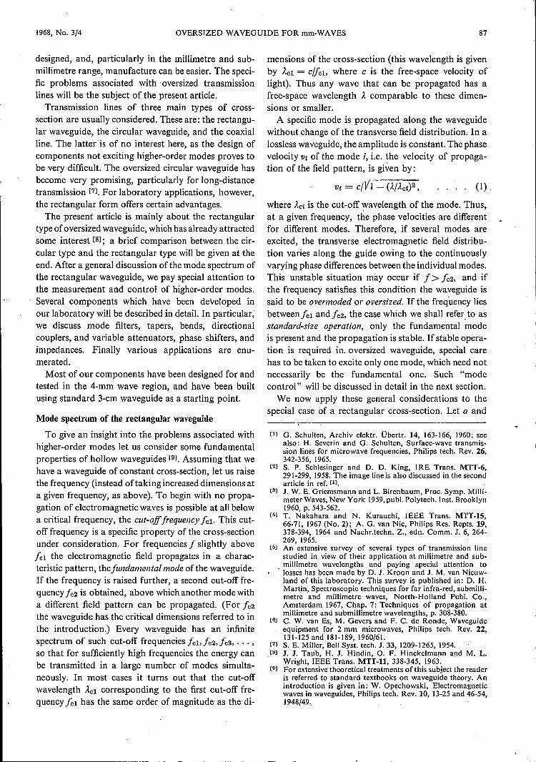
Fig. 14. The 900 E-plane bend (on the left) and the 90° H-plane bend (on the right), designedby the "optical approach", in which the wave propagation is assumed to take place along"rays".
our taper has only been optimized for low HlO-+ Haomode conversion.
The only part of the taper which is significant inmode conversion is the part where the unwanted highermode can propagate. The rest of the taper can be de-signed more or less arbitrarily: we chose a linear func-tion for a(z). We made the variation of b with z linearthroughout, since variation in height excites only thetypes H12, H32, ... , H14, H34, ... which always havesmall amplitudes on account of their small beat wave-lengths.
Bends
There are two different approaches to the design ofthemajority of the components for oversized waveguide.The first, used by most workers in this field [81 [171,
is the "optical approach", in which the propagationof electromagnetic energy is assumed to take placeessentially along "rays", which undergo reflection and
refraction, as in geometrical optics. This approach isuseful especially for a high degree of oversizing, sincein this case the fundamental HlO wave behaves verymuch like a plane wave. However, there are some com-ponents such as tapers and mode filters which cannotbe designed by using optical principles. It has beenfound very difficult to make these indispensible ele-ments with low enough mode conversion if the wave-guide is highly oversized. In the work described herewe therefore used a different approach, suitable for amedium degree of oversizing. This is the "waveguideapproach" in which the propagated wave is separatedinto the waveguide modes, between which conversionscan take place.
H- and E-plane bends designed by the optical ap-proach are shown infig. 14. The incident wave, whichmay be represented by a "ray", falls upon a planemirror at a certain angle and is reflected at the sameangle towards the output port. However, some diffrac-tion occurs, since in both waveguide arms a part of thewall has to be left out to permit the desired deflectionof the ray. As the wall currents in the broad walls of ahighly oversized waveguide are much higher than in the
narrow walls, this diffraction is obviously more markedin the E-plane bend (on the left in fig. 14). In waveguideterms diffraction means excitation of higher-ordermodes; these belong to the Eln and Hi« types for theE-plane bend and to the Hmo types for the H-plane bend.Although the Ei« and Hln modes can be absorbedby using the mode filters described above, the overalllosses become so excessive (several decibels) that theE-plane bend designed by the optical method is notvery attractive. On the other hand, the H-plane bendgives satisfactory results provided the waveguide issufficiently oversized. An extensive theoretical analysishas been given by Dr. C. J. Bouwkamp of this labora-tory [181.For instance, the power loss due to mode con-version into the Hmo modes has been shown to be lessthan 0.4 dB if the frequency exceeds eight times thecut-off frequency, in other words, if the waveguide ismore than about five times oversized. However, itshould be emphasized that the power loss in a complete
system may be substantially higher because of trapped-mode resonances.
Since the optical approach has proved to be unsatis-factory in the case of an E-plane bend, a solution basedon the waveguide principle has been sought. In thearrangement shown infig. 15the actual bend is made offlat waveguide, which is connected with the full-heightoversized waveguides by means of two tapers. In thebend section there is some mode conversion into theEi« and Hin modes; but if the height of the flat wave-guide does not exceed halfthe wavelength these modesare evanescent and do not appear at the ports. A bendof this type is usable from frequencies giving standard-size operation to those at which there is a high degreeof overmoding, because the quantity determining thecut-off frequency of the desired mode, i.e. the width,does not change. The power loss, which is only of theorder of a few tenths of a decibel, is mainly due to thewall losses in the flat guide.
[17] B. Z. Katsenelenbaum, Soviet ·Phys. Uspekhi 7, 385-400,1964/65; Radio Engng, Electronic Phys, 8, 1098-1106, 1963.
[lS] C. J. Bouwkamp, unpublished. See also: I. P. Kotik andA. N. Sivov, Radio Engng.r Electronic Phys. 10, 140-142,1965.

.--------------------------------- ~--- --
98 PHILIPS TECHNICAL REVIEW VOLUME 29
Fig. IS. The 90° E-plane bend designed from a "waveguide approach" in which the wave is split up into waveguide modes. Con-version into E,,, and Hi" can occur, but these modes do not propagate in the flat guide provided b i < À/2. In a design for use atÀ ~ 4 mm the following dimensions were chosen: a X b = 22.86 X 10.13 mm, r = 420 I11m; b, = 2 mm.
a
53
2
3+IIIII
l--l-------
'------v-------6
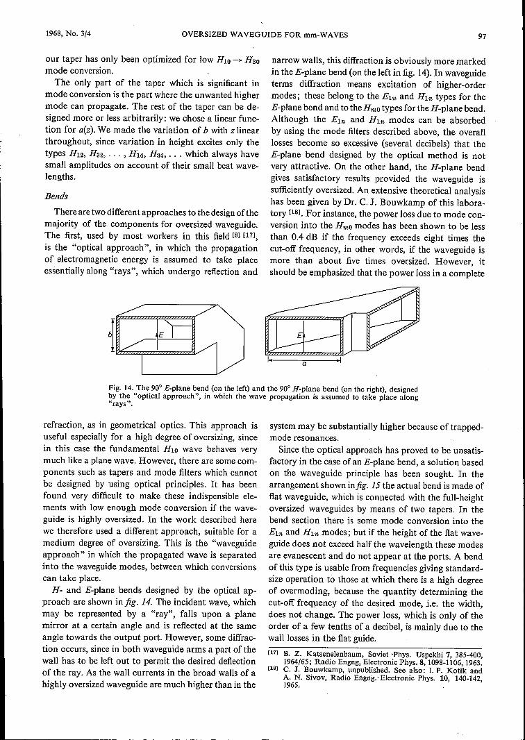
Fig. 17. Principle of a three-port directional coupler. At the left, transversecross-section; on the right, longitudinal cross-section. Power from port I isdivided in the ratio (b - yJ: y between the ports 2 and 3. Ports 2 and 3 aredecoupled. 4 metallic sheet, 5 semi-transparent resistive sheet, 6 higher-ordermode filter'2
t
Fig. 16. Directional coupler designed from optical principles. His in the plane of drawing. At the dielectric sheet S the incidentwave 1 is partly reflected (3), partly transmitted (4). There issome unwanted coupling J -+ 2 owing to diffraction, even withoutany sheet.
Directional couplers
A well-known optical design for a directional coupleris shown infig. 16. It consists of an H-plane cross-junc-tion of two waveguides, with a dielectric sheet placedin the diagonal plane of the cross. This sheet acts as asemi-transparent mirror and provides a directionalcoupling, as in optical interferometers. However, evenwithout any sheet, a fundamental mode incident in
Fig. 18. Practical design of a 3-dB three-port directional coupler,from the principle of fig. 17.
5cm
o
1968, No. 3/4 OVERSIZED WAVEGUIDE FOR mm-WAVES
one arm causes some radia-tion into the side arms ow-ing to diffraction. The dis-tribution of this deflectedpower as well as of the re-flected and transmittedpower among the differentmodes has been calculatedby Katsenelenbaum [17] andby Bouwkamp [18l. Thesediffraction phenomena giverise to certain errors in theperformance of the directi-onal coupler which decreasewith increasing degree ofovermoding. Special carehas to be taken if the direc-tional coupler is used closeto the cut-off freq uency ofa higher-order Hmo modewhich may give resonan-ces in a system.lf there is no special rea-
son for using a four-portdirectional coupler, and athree-port type of direction-al coupler with built-in loadis sufficient, the followingarrangement based on thewaveguide principle is to bepreferred [19]. A waveguideis divided into two partsby a septum parallel to thebroad walls (fig. 17). Thisseptum consists of twoparts: a metal sheet and aresistive film which is semi-transparent to microwaves.Power incident from the left(port 1) is divided betweenwaveguides 2 and 3 in theratio of their heights. Thisratio determines the coupling factor of the directionalcoupler. Port 2 does not couple to port 3, because intwo parallel guides separated by a homogeneous sheet,a wave propagating in one of the guides does not excitea wave propagating in the opposite direction in theother guide. The higher-order modes excited by the re-sistive sheet are attenuated by the mode filter at port 1.The resistive sheets of this filter and the resistive part ofthe septum are equivalent.to the built-in load used inconventional standard-size directional couplers. Amore practical form of oversized waveguide directionalcoupler is given in fig. 18. With this construction a di-
Some variable componentsIn principle the directional coupler described above
[19J S. B. Cohn, Microwaves 5, No. 6,62, 1966; G. W. Epprecht,International Microwave Symposium Digest, Boston, May1967, p. 10; W. K. Kahn, ibid. p. 54-57.
}2 :: ::Iy'---v------'
4Fig. 19. Variable attenuator derived from the directional coupler of fig. 17. The guide is againdivided by a metallic sheet I and resistive sheets 2. Power in the upper guide is absorbed in thematched load 3. The attenuation is varied by vertical displacement of the unit consisting of thesheets J and 2 and the load 3. Higher-order modes are filtered out, as before, by the modefilters 4.
rectivity of about 50 d B has been obtained for a couplingof 3 dB (À = 4 mm, standard 3-cm waveguide). A greatadvantage of the present device is the frequency inde-pendenee of the coupling, which is solely determinedby the physical dimensions. Like the E-plane bendshown in fig. 15 the directional coupler is inherentlybroadband.
99
100 PHILlPS TECHNICAL REVIEW
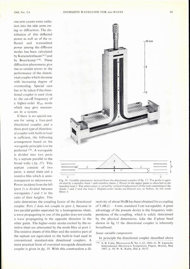
can also be used as a frequency-independent attenuator,if one arm is terminated in a matched load. Infig.19 twosuch directional couplers are connected symmetricallyin cascade, so that the input and output waveguidesare full-height again. The device can easily be made intoa variable attenuator by making the septum movable.As each ofthe directional couplers with one arm matchedis a reciprocal two-port the total attenuation (in dB)is theoretically equal to twice the coupling (in dB) ofeach directional coupler; it is given by (cf. fig. 19):
attenuation = 20 log (b/y).
VOLUME 29
caption. This "line stretcher" can be used in allcases where the variation of its total length causes nodifficulty.
A variable phase-shifter and a variable attenuatorconnected in cascade and terminated in a short-circuitconstitute a variable impedance. Since in this case theoutput port need not be accessible, the arrangementcan be simplified by using half of the attenuator shownin fig. 19. This gives the configuration oî fig. 21 wherethe metallic sheet of the directional coupler has clearlybecome superfluous. The magnitude of the reflectioncoefficient can be varied by vertical displacement of the
short-circuiting part togeth-er with the resistive sheetand the load: its val ue issimply given by yjb. Thephase is varied by the 1ine-stretcher described above,which is placed in front ofthe present device.
(J I)
fJ\'
Fig. 20. Variable phaseshifter (line stretcher). Thephase shift between the twoends of a waveguide is var-ied by varying the lengthof the line. By turning theknob the part I is made toslide in the transverse di-rection, thereby causingpart 2 of the waveguide toslide in the longitudinal di-rection over the fixed part3. The top and bottorn ofthe waveguide are partlyformed by J. 4 is a thinmetal sheet covering thehole of varying size be-tween 2 and 3.
Conclusions
Now that we have de-scribed the particular fea-tures of several special com-ponents at some length, letus summarize some princi-pal aspects of the design ofsingle-mode oversized wave-guide components. We haveseen that the corn ponentsdesigned from optical prin-ciples work satisfactorilyonly if the waveguide issufficiently oversized. If, onthe other hand, the wa ve-guide is more than about tentimes oversized, the tapersand mode filters - in-dispensable components formost applications - haveto be inconveniently long.The quasi-optical corn po-nents will therefore beusableonly in a limited frequencyinterval, roughly character-ized in practice by the limits"five times oversized" and"ten times oversized", cor-
responding to an octave. On the other hand, some ofthe components described in this paper and designedfrom "waveguide" principles, work over a frequencydecade, that is to say, between the frequencies corres-ponding to "not oversized" and "ten times oversized".
Measurements (À = 4 mm, standard 3-cm waveguide)have indicated a minimum attenuation of 0.5 dB, anda maximum attenuation of 50 dB.
Fig. 20 shows a simple construction of a variablephase-shifter; some of the details are explained in the

1968, No. 3/4 OVERSIZED WAVEGUIDE FOR mm-WAVES 101
Almost all components give rise to some modeconversion into unwanted modes. This phenomenon isannoying not only because of the loss in the powertransmitted in the fundamental mode, but also because
Fig. 21. Termination giving a reflection ofvariable magnitude andphase. This device, together with the variable phase shifter offig. 20(6 in this figure) constitutes a variable impedance. The magnitudeof the reflection is varied by vertical displacement of the part Jtogether with the resistive sheet 2. 3 is a load, 4 a 90° E-planebend, both reflectionless. 5 mode filter. The magnitude of thereflection coefficient is equal to ylb (cf. fig. 19).
of possible interactions between the higher-order modesexcited by different components and, in particular,the possible occurrence of trapped-mode resonances.On account of these effects mode filters have to be usedwhich suppress or at least reduce these interactions andresonances. Since for the higher-order modes of class 1(Emn and Hmn modes with 11 =F 0) almost ideal filterscan be constructed in the form of resistive sheets, thepreferred components should be those which only giveconversion into these modes. This is the case with theE-plane bend of fig. 15 and the directional coupler offig. 18.These components have the common characteris-tic that all longitudinal cross-sections parallel to thenarrow wall are identical. Furthermore, they are in-herently broadband because the only limitation to thefrequency of the dominant mode to be transmitted is alower limit: the cut-off frequency determined by thewidth of the waveguide.Tolerances in the form and dimensions of compo-
nents have not been discussed in this article. Due atten-tion has to be paid to precision manufacturing of thecomponents and careful alignment in a system, asany deviation from ideal dimensions, any discontinuityat the flanges or inhomogeneity along the guide, canin principle give rise to higher-order modes.
Finally, let us enumerate some of the applications ofoversized rectangular waveguide equipment:1) Short-distance transmission, e.g. in radar aerial
feeds.2) Measurements of physical properties of materials
such as dielectric constant, conductivity, surface im-pedance.
3) Simultaneous transmission of microwave signals ofseveral frequencies covering a wide band (multi-plex).
4) High-power transmission. This application, how-ever, may be limited by breakdown or excessiverise of temperature in some of the componentsdescribed in this paper.
5) It mayalso be possible to apply the oversized rec-tangular waveguide method to the submillimetreregion, by scaling down the components.
In applications such as these the rectangular waveguidehas proved to be superior to the circular waveguideoperated in the HOI mode. A serious drawback of theHOI circular mode is that it is very difficult to designmode-launchers and filters, which means that its useis justified only if full advantage can be taken of theextremely low loss in this mode. Mode control in thecircular guide is rather difficult, particularly since theHOI mode in this guide is degenerate with the Ellmode, so that mode conversion easily takes place.
Summary. The use of oversized waveguide for the transmission ofmillimetre waves has advantages over standard-size waveguide:the larger guide is easier to manufacture and to handle, the lossesare smaller, and very broadband components can be made. Formeasuring purposes in particular, single-mode operation of theoversized waveguide is essential, as with multimode operation thefield pattern is in practice unpredictable. If single-mode operationis to be achieved, mode control is necessary, i.e. measures haveto be taken to prevent the conversion of the fundamental modeinto higher-order modes, or to eliminate the effects of such con-version. An essential element for examining the mode conversionof components is the mode transducer, which converts a specifichigher-order mode into the fundamental mode. Another in-dispensable element for mode control is the mode filter, whichideally absorbs all the higher modes without attenuating the fun-damental mode. Several mode transducers and filters are de-scribed. Some ofthe oversized waveguide components discussed':tapers, E-plane bends, directional couplers, variable attenuators,phase shifters and impedances can be used over a 10 to 1 fre-quency band.