Embed Size (px)
Citation preview

A L T R A I N D U S T R I A L M O T I O N
Overrunning and Backstopping ClutchesFor Mining Applications
ARTEN Freios e Embreagens - Fone: 11 5594-8333

AS
910 0 Rev.B
Formsprag’s Quality Management System is certified to ISO9001:2008
and AS9100 Rev.B.
Formsprag overrunning and backstopping clutches are hard at work at mines around the world.
For over 50 years, Formsprag Clutch has been a recognized leader in designing, manufacturing, and delivering dependable long-lived overrunning clutches for a wide spectrum of applications in the mining industry.
By offering the broadest range of both sprag and ramp & roller type overrunning clutches and backstops available globally, Formsprag Clutch, together with our sister company Stieber Clutch in Germany, is the world’s leading authority for solving mining application challenges requiring overrunning clutches.
Backstopping ApplicationsLLH® (Long Life Holdbacks®)
LLH holdback clutches are mounted on the head shaft of the conveyor, typically on the side opposite the electric motor and gear reducer. The LLH clutch allows the headshaft to freely rotate in the driving direction while preventing any rotation in the opposite direction.
HSB (High Speed Backstops)
HSB units are intended for use as backstops on the high speed shaft or intermediate shaft of a reducer, and as holdbacks on the head shaft of conveyors. They use standard clutches with the addition of the oil reservoir. The oil reservoir is an aluminum casting with cooling fins. HSB models have a spacer replacing the seal at the reservoir end to permit free oil flow between clutch and reservoir. The reservoir has a flush oil sight gauge and a combination breather and oil filter.
FHB Backstopping Clutches
FHB is a high speed, centrifugal throw-out (C/T) Sprag type backstop with internal sealed ball bearings. It engages instantaneously and automatically to prevent any reverse shaft rotation. Operates at higher overrunning speeds and holds greater torque loads than competing backstops. A larger number of torque transmitting C/T Sprags reduce the hertzian contact stresses during backstopping leading to longer life than is possible with shoe designs.
Creep/Dual Drive ApplicationsFSO Overrunning Clutches
In northern climates where there are outdoor conveyor belts that do not run continuously, they can experience the conveyor belt idlers freezing up. A solution is to operate the belt at a low and creep speed to prevent this. The FSO overrunning clutch is the safest and easiest type of clutch for this application.
ARTEN Freios e Embreagens - Fone: 11 5594-8333

P-7043-FC 1/16 1
This class of applications is typified by standby and compound drives. For ex am ple, a steam turbine and a standby electric motor may be con nect ed to a sin gle driven shaft through overrunning clutches. The shaft can then be driven by either the turbine or the motor or both with no further modification of the installation. The turbine drive clutch au to mat i cal ly engages when the tur bine starts to drive, but au to mat i cal ly over runs when the load is transferred to the electric motor.
Considerations• Type of motor• Max starting torque• Internal combustion engines,
please consult Formsprag• Nominal driving torque• Range of driving speed• Inertia (WR2) of the driven masses• Range of overrunning speed• Number of starts during service life• Shaft diameter
Applications• Dual motor/engine drives• Conveyor belts• Creep and starter drives• Disengagement of centrifugal mass es
In backstopping or holdback* ap pli ca tions, one race is always fixed to a sta tion ary ground member. The function of the clutch is to permit ro ta tion of the mechanism, con nect ed to the other race, in one di rec tion only, and to prevent any ro ta tion in the reverse di rec tion at all times. Although the clutch nor mal ly overruns most of the time, it is re ferred to as a holdback or backstop in conveyors, gear reducers and sim i lar equipment because its func tion is to pre vent reverse rotation.
* “Holdback” is a name given to a back stopclutch when mounted on an inclined con vey orhead shaft.
Considerations• Motor breakdown torque• Maximum dynamic reverse torque
due to elasticity of the locked parts:elastic belts, shafts of more than9 feet (3 meters) long
• Range of overrunning speed• Number of torque applications
during service life• Shaft diameter
Applications• Inclined conveyors• Bucket elevators• Pumps• Gear drives• Fans
Overrunning clutch Backstopping clutch
Contents
Clutch Functions and Applications . . . . . 1
Overrunning Clutch Designs . . . . . . . . . . 2
Principles of Operation. . . . . . . . . . . . . . . 4
Selection. . . . . . . . . . . . . . . . . . . . . . . . . . 6
Models:. . . . . . . . . . . . . . . . . . . . . . . . . . 10
FS/ FSO/HPI . . . . . . . . . . . . .10
FHB. . . . . . . . . . . . . . . . . . . .14
HSB. . . . . . . . . . . . . . . . . . . .16
LLH . . . . . . . . . . . . . . . . . . . .20
Accessories . . . . . . . . . . . . . . . . . . . . . . 36
Stieber Interchange Chart . . . . . . . . . . . 41
CrossReference Part Numbers . . . . . . . 41
Engineering Data . . . . . . . . . . . . . . . . . . 42
Application Data Form . . . . . . . . . . . . . . 49
Conversion Factors . . . . . . . . . . . . . . . . 50
Rebuild and Overhaul Service . . . . . . . . 51
Clutch Functions
ARTEN Freios e Embreagens - Fone: 11 5594-8333

2 P-7043-FC 1/16
Overrunning Clutch DesignsRamp & Roller Overrunning Clutches
Ramp & Roller DesignThese rugged, reliable clutches consist of a cy lin dri cal out er race and an in ner race incorporating the ramps on which the rollers ride. The rollers are in di vid u al ly spring loaded to provide constant force between the rollers and both rac es. This force ensures in stan ta neous lockups when switch ing from the
overrun ning mode to the driv ing mode.
This design is also quite versatile, as the clutch can be operated in all three modes: over run ning, in dex ing and back stop ping. The out er race has great er over run ning speed ca pa bil i ty than the inner race, making the unit ideal for use as an indexing clutch, with the outer race acting as the re cip ro cat ing member.
Ramp-Roller DesignFor in creased ac cu ra cy in in dex ing ap pli ca tions, spec i fy “V” type, with stron ger en er giz ing springs.
Two Design StylesStieber overrunning clutches are available in two basic designs:
• Ramp & Roller
• Sprag
Overrunning clutch speed is a major determining factor in selecting the design best suited for each application. Ramp & roller clutches are used for applications with lowtomedium overrunning speeds and for indexing. Sprag clutches are the choice for applications with high overrunning speeds and for backstopping.
With each basic design there are several variations to choose from to meet specific application requirements. These variations include clutches with or without internal bearings, as well as a range of mounting flanges, covers and couplings.
Ball Bearing
Spring/Plunger
Seal
Locking Roller
Inner Race
Outer Race
Outer race
Locking roller
Inner race
Spring load ed plung ers
Individually spring loaded
OverrunningDrive
DriveOverrunning
When the outer race is the driving member, this is the resultant race activity.
ARTEN Freios e Embreagens - Fone: 11 5594-8333

P-7043-FC 1/16 3
Overrunning Clutch DesignsSprag Overrunning Clutches
and the clutch is free, or overruns. Either race may be the driven member or driving member.
If one race of the overrunning clutch is securely fixed to a grounded member, so that it cannot rotate, and the other race is free to turn, the free race will turn freely in one direction of rotation, but will be locked to the ground in the opposite direction.
In an overrunning clutch, the specific
Sprag DesignA sprag overrunning clutch consists of a cylindrical inner race and a cylindrical outer race surrounding it, with an annular space between the two races. A full complement of accurately formed sprags fills this annular space. Each sprag is essentially a strut placed between the races in such a way that it transmits power from one race to the other by a wedging action when either race is rotated in the driving direction. Rotation in the other direction disengages the sprags
D shape sprag design Free action PCE® design Inner race C/T design
Various Sprag Designs
Load Transmitting Formchrome® Sprags
Free Action Retainer
Oil Seal
Inner Race
Outer Race
Snap Ring
Lubrication Holes
Energizing Springs
Oil Seal
Snap Ring
Ball Bearings
sprag shapes have been developed to meet most conceivable types of clutch applications. Since different types of overrunning applications involve different loading characteristics, different sprag shapes are used to provide the greatest possible life, torque capacity, and functional characteristics for the three basic types of overrunning clutch applications: overrunning, indexing, and backstopping.
ARTEN Freios e Embreagens - Fone: 11 5594-8333

4 P-7043-FC 1/16
Principles of Operation
Ramp & Roller DesignRamp & roller clutches consist essentially of an out er race with a cylindrical inside diameter, an inner race with ramps, and a set of rollers which are individually spring loaded to provide constant contact between the rollers and both races. This arrangement assures instant action at all running speeds and guarantees immediate driving capability whenever one of the two races rotates with respect to the other in the drive direction.
ApplicationClutches of this type can be used in all types of overrunning, backstopping and indexing applications.
When used as an overrunning clutch the ramp & roller clutch should be mounted in such a way that the outer race is the overrunning member. This is especially important with higher overrunning speeds. In applications where the inner race overruns, the centrifugal force on the rollers results in lower overrunning speed limits.
When used as a backstop a ramp & roller clutch with rotating inner race is especially suited at lower speeds. If the RPM is higher than the RPM recommended in the tables, we suggest using a sprag type clutch.
When used as an indexing clutch the outer race should always be the oscillating member and the inner race should be the driven member. Otherwise, the inertia of the rollers and springs will lead to inaccuracies, especially at high index
DRIVE
DRIVEOUTER RACE DRIVE
INNER RACE DRIVE
OUTER-RACE OVER-RUN
INNER-RACE OVER-RUN
Sprag DesignThis spragtype design overrunning clutch generally consists of an inner race, an outer race, a set of sprags, a sprag retainer, energizing springs, and bearings.
The wedging of the sprags between the races transmits power from one race to the other. The sprags have a greater diagonal dimension across one set of corners than across the other (see Figure 1). The wedging action occurs when the relative rotation of the inner and outer races tends to force the sprag to a more upright position where the crosssection is greater.
OUTER RACE
OVERR
UN
INNER RACEDRIVE
Figure 3Gripping angle increases as load increases and annular space increases.
Figure 1Detail of sprag. Dimension “A” is greater than dimension “B.”
Gripping AngleWedging action depends upon the wedging, or gripping angle of the sprags between the races. The fundamental concept of sprag clutches requires that the coefficient of friction of the sprag, with respect to the inner race at the instant torque is applied in the drive direction, must be greater than the tangent of the gripping angle, GA. If the condition is not satisfied, wedging will not occur.
The gripping angle is determined by the construction of Figure 2, where points A and B are the points of contact of the sprag with the inner and outer races, respectively.
Sprags are designed to have a low initial gripping angle to insure positive initial engagement. As torque increases, the sprags produce radial forces which cause race deflections, which make the sprags roll to new positions. Sprags are usually designed to have an increasing gripping angle as they roll from overrunning position to maximum loadcarrying position.
A higher gripping angle reduces the radial load imposed by the sprag, thus permitting higher torques to be transmitted within the limits of race stretch and brinelling.
Sprag
Energizing Spring
Sprag Retainer
Inner Race
Outer Race
A B
Figure 2Geometry of sprag, showing gripping angle “GA.”
Higher Load
Lower Load
A
A1
B
GA
B1
GA1
Sprag
GrippingAngle (GA)
Inner Race
Outer Race
A
B
GA
frequencies. The use of thinner lubricating oil and stronger springs will provide higher indexing accuracy and can be supplied upon request.
ARTEN Freios e Embreagens - Fone: 11 5594-8333

P-7043-FC 1/16 5
Principles of Operation
Free action
In the Formsprag “free action” retainer all sprags are permitted to have free and independent action. During overrunning this allows each sprag independently to adapt itself to any variations in annular space caused by runout or by foreign matter which may inadvertently get inside the clutch. Since each sprag operates independently, it cannot transfer the effects of variations from one sprag to the next. With all sprags in uniform engagement at all times, the load is evenly distributed. The free action principle also distributes wear evenly for a minimum of wear on all components.
Formsprag and Stieber manufacture a wide variety of sprag sizes and shapes to meet the market requirements.
The C/T Sprag PrincipleCentrifugal Throwout, or C/T, retainer assemblies are designed for high speed inner or outer race overrunning, and lower speed drive conditions. C/T sprags are available in a variety of models. Model FSO sizes 300 through 700 are available with PCE or C/T sprag option with outer race overrunning.
Outer Race C/TIn the outer race centrifugally disengaging sprag design, the mass of the sprag is located so that when the outer race is overrunning, the centrifugal force of the sprags overcomes the force of the energizing spring causing the sprags to completely “lift off” of the inner race.
Inner Race C/TModel RSBI & RIZ sizes 20 through 240 are available with the inner race C/T feature.
In the inner race centrifugally disengaging sprag design, the mass of the sprag is located so that when the inner race is overrunning the centrifugal force of the sprags overcomes the force of the energizing spring causing the sprags to completely “pull away” from the outer race.
The point at which the sprags lift off of the inner or outer race is listed as the “liftoff speed.” The maximum drive speed is always le ss than the liftoff speed to insure positive sprag energizing.
The primary advantage of the centrifugal throwout sprag retainer is that when the sprags lift off the inner or outer race there is no rubbing contact in the clutch. Therefore, the life of the clutch is determined by the life of the bearings.
Note: In centrifugal throwout designs, the sprags lift off the inner or outer race during overrunning. Therefore, for drive conditions, C/T designs require that the driving speed be lower than the liftoff speed.
Lift Off
Sprag Energizing
Torque transmission
Lift-off
The sprags are energized by springs that act upon each end of each sprag. Formsprag has developed several different types of energizing springs, such as contracting springs, expanding springs and a torsional type spring. In each overrunning clutch the type of energizing spring used will reflect Formsprag’s broad experience in the design and application of overrunning clutches in the choice of a method of energizing best suited for the particular design of clutch.
In all cases, whether the spring is an expanding spring, a contracting spring, or a torsional spring, the spring design energizes each sprag individually without transfer of motion or effect from one sprag to the next.
PCE® spragPCE sprags are designed to overcome the effects of severe torsional and linear vibrations as well as high transient torque overloads. It is a Formsprag exclusive. This design, which provides built in protection from otherwise damaging overloads, is now standard in model sizes 300 through 700.
Formchrome® extends sprag lifeUltrahard Formchrome sprags provide extralong life, maximum wear resistance and lower maintenance costs. Formchrome sprags — exclusive with Formsprag — are made by diffusing chromium into the surface of hardened high carbon alloy steel to form a chromiumcarbide alloy.
1000 times enlargement
ARTEN Freios e Embreagens - Fone: 11 5594-8333

6 P-7043-FC 1/16
Selection GuideSelection Procedure
When a clutch is to be selected on the basis of torque calculation, follow the eleven steps below:
1. Calculate load torque to betrans mitted by the clutch.
5250 x HPTorque (lb.ft.) =
RPM
or
Torque (Nm) = lb.ft. x 1.356
2. Select the proper service factorfrom the appropriate table on page9.
3. Determine the design torque bymultiplying the load torque by theservice factor.
4. Check the key and shaft stressbefore making a final clutchselection since this may determinethe maximum allowable drivetorque capacity.
5. Determine the overrunning anddrive speed along with which racewill overrun.
6. Select a clutch MODEL and SIZEfrom the catalog based on designtorque, bore size, overrunningspeed and dimensions for properfit into the available space.
7. If the outer race is the overrunningmember, then determine if the C/Toption can be used for the clutchmodel selected.
a. A Centrifugal Throwout (C/T)model clutch may be used ifthe drive speed is less thanthe maximum C/T drive speedand the overrunning speed ishigher than the liftoff speed.
b. A C/T model clutch may notbe used when the drive speedis higher than the maximumC/T drive speed.
c. For overrunning speeds otherthan listed, contact thefactory.
8. When higher speeds arerequired select the LABYRINTHGREASE SEAL option listedin the Specification chart foreach clutch model or contactFormsprag Application EngineeringDepartment.
9. Determine the shaft size, boreand key size requirement of theclutch from the catalog. Referto the BORE SIZES/ SHAFTTOLERANCES chart on pages42 and 43 for the ACTUAL BORESIZE that will be supplied withthe clutch. If the actual bore sizerequired is other than that listed, contact the factory.
10. Select the type of LUBRICANT,oil or grease, for the clutch modelwhere appropriate. It should benoted that many of the clutchmodel are available in either oil orgrease only. If the Labyrinth greaseseal option is selected in step 8above, the clutch must be greaselubricated.
11. Determine the DIRECTION OFROTATION for the model selectedwhere necessary. When viewingthe clutch from the end as shownin the catalog, if the inner raceis to rotate freely in the CCWdirection and drive in the CWdirection it is a Right Hand(RH) rotation. Left Hand (LH) isopposite. See clutch rotation onpage 8.
The torque values listed in this catalog are based upon normal use with 1 million load cycles at full catalog torque and receiving proper care and maintenance. For Models FSO, HPI, FSA and SB the torque ratings are based upon using only one end face to transmit.
Caution: Consult factory for reciprocated type prime mover and any inclined or vertically mounted applications.
Special DesignsWhile the wide range of sizes and capa cities covered by this catalog’s line of clutches will cover substantially all industrial needs, it is sometimes necessary to design and build clutches to meet specialized requirements.
Special designs can also take advantage of a selfcontained lubrication system or lubricant contained within the customer’s machine. In such cases, lubrication could be introduced through the inner race or through clutches assembled without seals to permit a free flow of oil through the clutch. Since other factors may affect selection of clutches in both indexing and holdback cases, consult our Application Engineering Department for assistance.
ARTEN Freios e Embreagens - Fone: 11 5594-8333

P-7043-FC 1/16 7
Selection GuideHow To Order
1) FSO – 700 C/T / 2.25 .625 x .322) FSR – 16 / 1.00 .50 x .25 GR RH3) HPI – 900 L / 4.50 1.00 x .50 GR
Example:
Model
Size
Options (Labyrinth Seal, C/T Sprag)
Nominal Bore
Keyseat Size*
Lubricant (Blank Oil, GR Grease)
Direction of Rotation
* If keyseat is not specified when ordering, the clutch will be supplied with the available standard keyseat.
When placing an order always use the part number in addition to the model number if available.
The part number is marked on the clutch and listed in the price sheets. There is a unique part number for each design and bore combination and the format is as follows:
Format is
CL (clutch)
Base model no. (5 digits)
Clutch Bore (1, 2 or 3 digits)
Special Design of the same bore (1, 2 or 3 digits)
Example is CL421561232
The model number is marked on the clutch
and listed in the product catalog.
Example:1. FSO 700 model clutch, optional
C/T retainer, 2.2485/2.2500” bore,.625 x .32 keyseat, oil lubricated.
2. FSR 16 model clutch, 1.000/1.001”bore, .50 x .25 keyseat, greaselubricated, right hand rotation.
3. HPI 900 model clutch, optionalLabyrinth grease seals, 4.498/4.500”bore, 1.00 x .50 keyseat, greaselubricated.
CL XXXXX – XXX – XX
ARTEN Freios e Embreagens - Fone: 11 5594-8333

8 P-7043-FC 1/16
Selection Guide
Drag TorqueIn an overrunning clutch the drag or resistance to freely turn is a result of the additive values of seal drag, bearing drag and sprag energizing drag. This clutch drag torque is noted as “resistance after runin” and is listed for each model on its data page. The drag (resistance after runin) torque values for new clutches will be higher at first and after 12 to 24 hours of overrunning at standard motor speeds will reduce to cataloglisted values. When a clutch is overrunning, the drag torque is exerted upon the lower speed race and any attached drive components.
Overrunning Clutches
Overrunning SpeedsThis is the maximum speed differential between the inner and outer races. When one race is stationary and the other overruns, clutch selection may be based on maximum overrunning speeds shown in the catalog.
Same direction of rotationIf both races rotate in the same direction at different speeds, the overrunning speed is the difference in their speeds.
Opposite direction of rotationIf the races rotate in opposite directions, the overrunning speed is the sum of their speeds.
If the overrunning clutch design is not symmetrical, then the clutch rotation will need to be determined, and this information (RH or LH) must be provided at time of order placement.
To establish rotation of a clutch, look at the clutch from the end specified by the arrow for each clutch series. If the inner race drives the outer race in the clockwise direction it is a right hand rotation.
Clutch rotation
F ree D riveD rive F ree Outer Race
Inner Race
Bore
Right Hand Rotation ShownLeft Hand Rotation Shown
ARTEN Freios e Embreagens - Fone: 11 5594-8333

P-7043-FC 1/16 9
Selection Guide
Service Factors
Formsprag and Stieber Overrunning ClutchesClutches are suitable for many different power transmission applications. Please refer to this table for the proper service factor for your application.
Typical prime movers are listed at the left, types of loads across the top, and your service factor opposite the typical prime movers.
When torsional or linear vibration is present, use an FSO series clutch and increase the service factor at least 50%. For severe vibration, a greater service factor increase is necessary. To conform with couplings manufacturer’s recommendations, use a minimum service factor of 1.5 on all Clutch Couplings.
Driven Equipment Load Classifications
Light Steady LoadsStarting torque is equal to or slightly greater than running torque.
Moderate LoadsHigh starting torque or above average running torque.
Medium LoadsStarting torque is approximately double running torque.
Heavy-Duty LoadsHigh starting torque, shock loading, light torque reversals during drive.
Centrifugal pumps, uniformly loaded conveyors, lightduty fans and blowers, liquid mixers and agitators, centrifugal compressors, lobe and vane type blowers, gear pumps, textile machinery, woodworking machinery.
Hot oil pumps, heavyduty centrifugal pumps, cooling towers, slurry agitators, boiler feed pumps, hoists, conveyors.
Dredge pumps, dynamometer drives, lightduty hammermills, lineshafts, paperconverting machinery, rotary kilns, rotary or screwtype pumps for high viscosity fluids.
Mine ventilating fans, reciprocating pumps or compressors, papermaking machinery, heavyduty hammermills, ore crushers, pulverizing mills.
Steam, gas or air turbine 1.00 1.50 1.50 2.50
AC electric motor 1.25 1.50 1.50 2.50
DC electric motor with DOL startAC electric motor
1.25 1.50 1.75 3.00
Gasoline, natural gas, propane or Consult Consultother spark ignition engine
3.0 3.0Formsprag Formsprag
Consult Consult Consult ConsultDieselFormsprag Formsprag Formsprag Formsprag
Pri
me
Mo
ver
Overrunning & Backstopping Applications Service Factors
Indexing Applications Service Factors
FS-02, 04, 05 FSR 6 to 16 Roller Type of Load FSR-3 & 5 HPI FSO Design
Less than 90° or less than 150 strokes/min. 3 2 2 2
Over 150 strokes/min. 4 2 N/A 3
When angle is greater than 90° and over 200 strokes/min.
4 2 N/A 2.5
* Recommended for maximum performance and maximum life.
Note: In all cases where considerable vibration is present, a higher service factor may be needed (possibly up to 6).
DOL = Direct on Line
ARTEN Freios e Embreagens - Fone: 11 5594-8333

10 P-7043-FC 1/16
General Purpose ClutchesFSO/HPIOverrunning, Indexing, Backstopping Ball Bearing Supported, Sprag Clutches
The Model FSO clutches must be axially restrained, see accessories page 36 for set collars, restraint keys and OSHA covers, etc. All fasteners are recommended to be grade 8 bolts.
Typical Mounting Arrangement
Torque Resistance ShippingCapacity after run-in FSO HPI Weight
lb.ft. Inner Outer Inner Outer Inner Outer Max. Sprag lb.ft. oz oz lb. Size (Nm) Race Race Race Race Race Race drive lift-off (Nm) (ml) (ml) (kg)
300 275
3,000 900 3,600 900 3,000 6,000 1,100 1,300.13 .25 .50 3.5
(374) (.18) (7.0) (14.0) (1.6)
400 300
2,800 850 3,600 850 2,800 5,000 1,100 1,300.20 .33 .67 6
(408) (.27) (9.9) (19.8) (2.7)
500 1,175
2,500 800 3,000 800 2,500 4,000 1,000 1,200.23 .75 1.25 10.5
(1598) (.31) (22.0) (35.0) (4.8)
550 1,885
1,175 800 — — — — — —.35 1.75
— 12
(2564) (.47) (52.0) (5.4)
600 2,250
2,200 750 2,400 750 2,200 3,600 1,000 1,200.46 1.75 3.00 19
(3060) (.62) (52.0) (84.0) (8.6)
650 2,375
900 600 — — — — — —.80 6.00
— 24
(3230) (1.08) (168.0) (10.8)
700 5,000
1,600 450 2,000 450 1,600 2,500 800 1,0001.15 6.00 10.00 42
(6800) (1.56) (168.0) (280.0) (19)
Note: Check key and shaft stress before making final clutch selection since this may determine the maximum allowable drive torque capacity. Shaft keys are not provided with the clutches on sizes 300 through 700.
All models contain PCE sprags with Formchrome® and Formsprag “Freeaction” retainers except models FSO 550 & FSO 650. Standard clutches and all C/T clutches are oil lubricated. Grease lubrication is available for applications where maintenance is inadequate, or where higher inner race overrunning speeds are required. These clutches mount on a throughshaft, with the inner race driven by a key. The ground O.D. of the outer race is designed as a pilot or mounting surface for attaching parts and is concentric with the bore. Tapped holes are provided in each end of the outer race for securing these parts to the clutches. Refer to Bore Sizes/Shaft Tolerances chart for mounting data, page 42.
For vertical mounting, contact Application Engineering.
Model FSOGeneral purpose, ballbearing clutches suitable for overrunning, backstopping and light to mediumduty indexing applications. They are oil lubricated and equipped with lip type seals. Grease is available. Increased speeds are possible with steel labyrinth seals.
C/T Sprag Models (FSO Only)C/T sprag clutches are ideal for applications with high speed outer race overrunning and low speed driving. Available with oil lubrication only.
Model HPIEspecially designed for medium to heavy-duty indexing applications, or applications in excess of 150 strokes/min. to provide the maximum in dependable, uniform, long life performance except models FSO 550 & FSO 650. They are oil lubricated and equipped with lip type seals. Grease is available.
Oil Lubricated ClutchesFSO300 through 700 clutches are shipped from the factory with Mobil DTE Heavy Medium oil.
HPI300 through 700 clutches are shipped from the factory with Mobil DTE Light oil.
Specifications
Oil and GreaseLip Seals
Lubrication
Oil or Oil Grease onlyOverrunning
Speed
C/T Sprag Models
LabyrinthGrease Seals
Overrunning Speed
Standard Models
Maximum RPM
Grease Lubricated ClutchesFSO300 through 700 clutches are shipped from the factory packed with Fiske Brothers Lubriplate LowTemp grease.
HPI300 through 700 clutches are shipped from the factory with Mobil DTE Light.
OSHA cover kits are available for Models FSO & HPI400 through 700, see page 39 for details.
For further information, write for Installation and Maintenance Bulletin No. 2219 for the FSO series and No. 2213 for the HPI series.
ARTEN Freios e Embreagens - Fone: 11 5594-8333

P-7043-FC 1/16 11
General Purpose ClutchesFSO/HPI
Bore sizes and keyseats**** inches (mm)
Notes:
Angle — oil hole to mounting bolt hole Model 300, 400, 500 = 45°
600 = 15° 700 = 0° or 30° (offset from center of outer race)
Snap ring is located on the outboard side of the oil seal on Models 400, 600 and 700. On Models 300 and 500, snap ring is inboard of the oil seal.
Dimensions inches (mm)
AD
Chamfer G
E FB
C
.250-28Oil Hole
(see note)
Snap RingLocations(see note)
FSO OSHA cover kits are designed for shaft end mounted FSO or HPI clutches and available from Formsprag from size 400 through 1027. These cover kits provide not only the stationary cover enclosure required by OSHA, but provide additional protection for the clutch from abrasive environments as well.
Note: OSHA requires that a stationary guard must enclose clutches with rotating projecting parts and operating seven (7) feet or less above the floor.
G Size A B C D E F Number Thread Depth
3002.50 3.000/2.998 2.38 .06 x 45° 1.12 2.625
4 @ 90° .250-28 .50
(63.50) (76.20/76.15) (60.45) (1.58 x 45°) (28.58) (66.67) (12.70)
4002.75 3.500/3.498 2.69 .06 x 45° 1.19 2.875
4 @ 90° .312-24 .63
(69.85) (88.90/88.85) (68.26) (1.58 x 45°) (30.15) (73.02) (16.00)
5003.50 4.250/4.248 3.38 06 x 45° 1.77 3.625
4 @ 90° .312-24 .63
(88.90) (107.95/107.90) (85.72) (1.58 x 45°) (45.0) (92.07) (15.87)
550 3.25 4.750/4.748 3.125 0.08 2.75 4.25
6 @ 60° .312-24 .54
(82.55) (120.65/120.60) (79.38) (69.85) (107.95) (13.72)
2.50
6003.75 5.375/5.373 3.63 .06 x 45° (63.50) 4.750
6 @ 60° .312-24 .63
(95.25) (136.53/136.47) (92.07) (1.58 x 45°) †2.72 (120.65) (15.87) (69.09)
650 3.50 6.500/6.498 3.375 0.09 3.187 5.75
8 .375-24 .79
(88.90) (165.1/165.05) (85.72) (80.94) (146.05) (20.06)
3.56
7005.00 7.125/7.123 4.88 .06 x 45° (90.42) 6.250
8† .375-24 .75
(127.00) (180.97/180.92) (123.82) (1.58 x 45°) †4.00 (158.75) (19.05) (101.60)
Notes:† Six holes equally spaced at 60° plus two extra holes at 180°. Six hardened mounting screws are adequate for torque
loads up to 3000 lb.ft. (4068 Nm). Use eight hardened mounting screws for torque loads above these values.‡ The “E” dimension is larger for this bore size.
Bore Bore Range Size Size Keyseat Min. Max.
.500 1/8 x 1/16 (12.70) (3.18 x 1.57)
.625 3/16 x 3/32 .500 .750 300 (15.87) (4.75 x 2.36)
15mm ***5 x 2.3mm*** (12.70) (19.05) .750 3/16 x 3/32
(19.05) (4.75 x 2.36).500 1/8 x 1/16
(12.70) (3.18 x 1.57) .625 3/16 x 3/32
(15.87) (4.75 x 2.36) .437 .875 400 18 mm ***6 x 2.8mm***
.750 3/16 x 3/32 (11.10) (22.22) (19.05) (4.75 x 2.36)
.875 3/16 x 1/16 (22.22) (4.75 x 1.57)
.875 3/16 x 3/32 (22.22) (4.75 x 2.36) 1.000 1/4 x 1/8
(25.40) (6.35 x 3.18) 1.125 1/4 x 1/8 .750 1.312 500 (28.57) (6.35 x 3.18) 30mm ***10 x 3.3mm*** (19.05) (33.32) 1.250 1/4 x 1/8
(31.75) (6.35 x 3.18) 1.312 1/4 x 3/32
(33.32) (6.35 x 2.29) 1.250 1/4 x 1/8
(31.75) (6.35 x 3.18) 1.312 3/8 x 3/16
550(33.32) (9.52 x 4.75) 1.00 1.625
1.5000 3/8 x 3/16 (25.40) (41.27) (38.10) (9.52 x 4.75) 1.625 3/8 x 1/8
(41.27) (9.52 x 3.18)1.250 1/4 x 1/8
(31.75) (6.35 x 3.18) 1.375 3/8 x 3/16
(34.92) (9.52 x 4.75) 1.5000 3/8 x 3/16 (38.10) (9.52 x 4.75) 40mm ***12 x 3.3mm*** .937 *†2.250*‡
600 1.625 3/8 x 3/16 (41.27) (9.52 x 4.75) (23.80) (57.15)
1.750 3/8 x 3/16 (44.45) (9.52 x 4.75) 45mm ***14 x 3.8mm*** 50mm ***14 x 3.8mm*** 2.000 3/8 x 1/8
(50.80) (9.52 x 3.18) 1.937 1/2 x 1/4
(49.20) (12.70 x 6.35) 2.000 1/2 x 1/4
(50.80) (12.70 x 6.35)
6502.250 1/2 x 1/4 1.69 2.500
(57.15) (12.70 x 6.35) (42.85) (63.5) 2.437 5/8 x 1/8
(61.90) (15.87 x 3.18) 2.500 5/8 x 1/8
(63.50) (15.87 x 3.18)1.937 1/2 x 1/4
(49.20) (12.70 x 6.35) 50mm 14 x 3.8mm 2.000 1/2 x 1/4
(50.80) (12.70 x 6.35) 2.250 1/2 x 1/4
(57.15) (12.70 x 6.35) 60mm ***18 x 4.4mm*** 2.437 5/8 x 5/16
700(61.90) (15.87 x 7.93) 1.875 †*3.250**‡
2.500 5/8 x 5/16 (47.62) (82.55) (63.50) (15.87 x 7.93) 65mm ***18 x 4.4mm*** 2.750 5/8 x 7/32
(69.85) (15.87 x 5.53) 70mm ***20 x 4.9mm*** 2.937 5/8 x 1/8
(74.60) (15.87 x 3.18) 75mm ***20 x 4.9mm*** 80mm ***22 x 5.4mm***
* 1/2 x 1/8 keyway. ** 3/4 x 1/4 keyway.*** Contact Formsprag for keyseat information.**** For Bore Sizes/Shaft Tolerences, see page 42.‡ The “E” dimension is larger for this bore size.
ARTEN Freios e Embreagens - Fone: 11 5594-8333

12 P-7043-FC 1/16
General Purpose ClutchesFS/FSO/HPIOverrunning, Indexing, Backstopping Ball Bearing Supported, Sprag Clutches
All models contain Formchrome® sprags and Formsprag “Freeaction” retainers. These clutches mount on a throughshaft, with the inner race driven by a key. Standard keys are supplied by Formsprag at no additional charge. The ground O.D. of the outer race is designed as a pilot or mounting surface for attaching parts and is concentric with the bore. Tapped holes are provided in each end of the outer race for securing these parts to the clutch. Refer to Bore Sizes/Shaft Tolerance chart for mounting data, page 42.
For vertical mounting, contact Application Engineering.
Model FSOAllows higher inner race overrunning speeds than FS series. They are also suitable for general overrunning and light to mediumduty indexing applications.
They are grease lubricated and equipped with grease seals.
Model HPIAre especially designed for medium to heavyduty indexing applications, or applications in excess of 150 strokes/ min. to provide the maximum in dependable, uniform, long life performance. They are oil lubricated and equipped with lip type seals. Grease is available.
Model FSSuitable for general overrunning, backstopping and light to mediumduty indexing applications. They are oil lubricated and equipped with liptype seals.
C/T Sprag Models (FS Only)Ideal for applications with high speed outer race overrunning and low speed driving. Available with oil lubrication only.
Oil Lubricated ClutchFS750 through 1027 clutches are shipped from the factory with Mobil DTE Heavy Medium oil.
HPI750 through 1027 clutches are shipped from the factory with Mobil DTE Light oil.
Torque Resistance ShippingCapacity after run-in FSO HPI FS Weight
lb.ft. Inner Outer Inner Outer Inner Outer Max. Sprag lb.ft. oz oz oz lb. Size (Nm) Race Race Race Race Race Race drive lift-off (Nm) (ml) (ml) (ml) (kg)
750 7,000
1,000 650 1,800 650 1,000 1,800 650 8003.75 7.5 13 7 83
(9520) (5.08) (222) (384) (207) (38)
800 13,000
850 525 1,500 525 850 1,500 525 6755.25 7.5 15 8.5 102
(17,680) (7.12) (222) (444) (251) (46)
900 18,000
700 500 1,350 500 700 1,350 500 6506.25 18 16 11.5 156
(24,480) (8.47) (532) (473) (340) (71)
1027 27,000
500 375 1,100 375 500 1,100 375 47510.00 22 32 16 250
(36,720) (13.56) (651) (946) (473) (113)
Notes:* FSO-1027 C/T Sprags are not Formchromed.Check key and shaft stress before making final clutch selection since this may determine the maximum allowable drive torque capacity.FSO-750 only, shipped with labyrinth seals.Shaft keys are provided with the clutches on sizes 750 and up.
Specifications
Lip SealFS & FSO
Lubrication
Grease OilOverrunningSpeed
C/T Sprag Models*
LabyrinthFSO
Overrunning Speed
Standard Models
Maximum RPM
Grease Lubricated ClutchFSO750 through 1027 clutches are shipped from the factory packed with Fiske Brothers AeroLubriplate grease.
HPI750 through 1027 clutches are shipped from the factory with Mobil DTE Light.
OSHA cover kits are available for Models FS, FSO & HPI750 through 1027, see page 39 for details.
For further information, write for Installation and Maintenance bulletin No. 2219 for FS and FSO series, and No. 2213 bulletin for the HPI series.
The Model FSO clutches must be axially restrained, see accessories page 36 for set collars, restraint keys and OSHA covers, etc. All fasteners are recommended to be grade 8 bolts.
Typical Mounting Arrangement
ARTEN Freios e Embreagens - Fone: 11 5594-8333

P-7043-FC 1/16 13
General Purpose ClutchesFS/FSO/HPI
A
E
GB
E
CF
Chamfer
D
.500-20Oil Holes (4)(see note)
H
Notes:
Angle — oil hole to mounting bolt hole Model 750 = 0° or 30°
900 = 0° or 18° 800 = 0° or 45°
1027 = 15°
Dimensions inches (mm)
Bore sizes and keyseats**† inches (mm)
H Size A B C D E F G Number Thread Depth
7506.00 8.750/8.748 5.88 4.25 1.25 .06 x 45° 7.00
8* .500-20 1.00
(152.4) (222.25/222.20) (149.22) (107.95) (31.75) (1.58 x 45°) (177.80) (25.40)
8006.00 10.000/9.998 5.88 5.50 1.25 .06 x 45° 8.94
8 @ 45° .500-20 1.00
(152.4) (254.00/253.95) (149.22) (139.70) (31.75) (1.58 x 45°) (227.01) (25.40)
9006.38 12.000/11.997 6.25 6.38 1.38 .06 x 45° 9.75
10 @ 36° .625-18 1.25
(161.9) (304.80/304.72) (158.75) (161.92) (34.92) (1.58 x 45°) (247.65) (31.75)
10276.63 15.000/14.997 6.50 9.00 1.38 .13 x 45° 11.75
12 @ 30° .625-18 1.00
(168.3) (381.00/380.92) (165.10) (228.60) (34.92) (3.17 x 45°) (298.45) (25.40)
* Six holes equally spaced at 60° plus two extra holes at 180°. Six hardened mounting screws are adequate for torque loads up to 5100 lb.ft. (6915 Nm). Use eight hardened mounting screws for torque loads above these values.
** For finished dimensions of keys supplied with the clutch, contact Formsprag.
Bore Bore Range Size Size Keyseat Min. Max..
2.437 5/8 x 5/16 (61.90) (15.87 x 7.94) 2.500 5/8 x 5/16
(63.50) (15.87 x 7.94) 65mm ***18 x 4.4mm*** 2.750 5/8 x 5/16
(69.85) (15.87 x 7.94) 70mm ***20 x 4.9mm***
7502.937 3/4 x 3/8 2.250 3.437
(74.60) (19.05 x 9.52) (57.15) (87.30) 75mm ***20 x 4.9mm*** 3.000 3/4 x 3/8
(76.20) (19.05 x 9.52) 80mm ***22 x 5.4mm*** 3.250 3/4 x 1/4
(82.55) (19.05 x 6.35) 3.437 3/4 x 3/16
(87.30) (19.05 x 4.75)3.000 3/4 x 3/8
(76.20) (19.05 x 9.52) 80mm ***22 x 5.4mm*** 3.250 3/4 x 3/8
(82.55) (19.05 x 9.52) 85mm ***22 x 5.4mmv*** 3.437 7/8 x 7/16
(87.30) (22.23 x 11.11) 3.500 7/8 x 7/16
(88.90) (22.23 x 11.11) 90mm ***25 x 5.4mm*** 2.625 4.437
800 3.750 7/8 x 7/16 (95.25) (22.23 x 11.11) (66.67) (112.70) 100mm ***28 x 6.4mm*** 3.937 1 x 1/2
(100.00) (25.40 x 12.70) 4.000 1 x 1/2
(101.60) (25.40 x 12.70) 4.250 1 x 3/8
(107.95) (25.40 x 9.52) 110mm ***28 x 6.4mm*** 4.437 1 x 1/4
(112.70) (25.40 x 6.35)100mm ***28 x 6.4mm*** 4.000 1 x 1/2
(101.60) (25.40 x 12.70) 4.250 1 x 1/2
(107.95) (25.40 x 12.70) 110mm ***28 x 6.4mm*** 4.437 1 x 1/2
(112.70) (25.40 x 12.70) 4.500 1 x 1/2
(114.30) (25.40 x 12.70) 120mm ***32 x 7.4mm*** 3.625 5.437 9004.750 1 x 1/2 (92.07) (138.10)
(120.65) (25.40 x 12.70) 4.937 1 x 3/8
(125.40) (25.40 x 9.52) 5.000 1 x 3/8
(127.00) (25.40 x 9.52) 130mm ***32 x 7.4mm*** 5.250 1 x 1/4
(133.35) (25.40 x 6.35) 5.437 1 x 1/4
(138.10) (25.40 x 6.35)4.937 1 1/4 x 5/8
(125.40) (31.75 x 15.87) 130mm ***36 x 8.4mm*** 150mm ***45 x 10.4mm*** 6.000 1 1/4 x 5/8
(152.40) (31.75 x 15.87) 6.250 1 1/2 x 1/2
(158.75) (38.10 x 12.70) 4.937 7.000 1027 6.625 1 1/2 x 1/2
(168.27) (38.10 x 12.70) (125.40) (177.80) 6.750 1 1/2 x 1/2
(171.45) (38.10 x 12.70) 6.875 1 1/2 x 1/2
(174.62) (38.10 x 12.70) 175mm ***45 x 10.4mm*** 7.000 1 1/2 x 7/16
(177.80) (38.10 x 11.10)*** Contact Formsprag for keyseat information.† For Bore Sizes/Shaft Tolerences, see page 42.
ARTEN Freios e Embreagens - Fone: 11 5594-8333

14 P-7043-FC 1/16
Backstopping ClutchesFHBBackstopping Ball Bearing Supported, Sprag Clutches
Falk® is a registered trademark of Rexnord Industries, LLC.
Model FHB is directly interchangeable with the older FALK® Model BIF external high-speed backstop.
Model FHB is a high speed, centrifugal throwout (C/T) Sprag type backstop with internal sealed ball bearings. This selfcontained design is completely maintenance free. It requires no relubrication, no external control, and no adjustment. It engages instantaneously and automatically to prevent any reverse shaft rotation. Model FHB operates at higher overrunning speeds and holds greater torque loads than competing backstops. A larger number of torque transmitting C/T Sprags reduce the hertzian contact stresses during backstopping leading to longer life than is possible with shoe designs.The FHB backstop is mounted on a throughshaft with its
Specifications
Torque Shipping Capacity Overrunning Speed Weight
lb.ft. Inner Race RPM lb. Size (Nm) Min Max (kg)
FHB-101,734
400 2,40031
(2350) (14)
FHB-201,734
400 2,00063
(2350) (29)
FHB-604,130
400 1,800158
(5600) (72)
The Model FHB can be axially restrained by a cotter pin in the reaction pin
Typical Mounting Arrangements
inner race driven by a key, and its integral outer race torque arm prevented from rotating through a clearance fit interface with a fixed reaction pin. The reaction pin may also be used to provide axial restraint of the backstop on the rotating shaft. Typical uses for the Model FHB backstop include inclined conveyors, bucket elevators, and other applications where a rotating shaft must be absolutely prevented from rotating in a reverse direction, as commonly found in mining, aggregates, material handling, and other industries. The high speed capability of the unit make this backstop ideal for mounting on double extended input shafts of gear reducers. The overrunning speed of the rotating shaft should be greater than 400 RPM to assure C/T Sprag “liftoff”.
Grease Lubricated Backstops, the Model FHB is shipped from the factory lubricated for life and the ambient operating temperatures range is from 40°F (40°C) to 150°F (65°C).Optional OSHA cover kits are available for all three sizes. See page 39.
ARTEN Freios e Embreagens - Fone: 11 5594-8333

P-7043-FC 1/16 15
Backstopping ClutchesFHB
BOREModel No. Min Max A B C D E
FHB-10 1.13 1.88 6.88 8.38 4.13 4.13 0.81
(28.70) (47.75) (174.75) (212.85) (104.90) (104.90) (20.5)
FHB-20 1.75 2.25 8.23 11.26 5.50 6.00 1.25
(44.45) (57.15) (209.04) (286.00) (139.70) (152.40) (31.75)
FHB-60 2.25 3.75 12 15.25 6.50 7.75 1.88
(57.15) (95.25) (304.80) (387.35) (165.10) (196.85) (47.75)
Dimensions – Formsprag FHB (mm)
BOREModel No. Min Max A B C D
10BIF 1.13 1.63 7.28 8.59 4.13 4.13
(28.70) (41.40) (184.91) (218.19) (104.90) (104.90)
20BIF 1.75 2.25 10.28 12.27 5.50 6.00
(44.45) (57.15) (261.11) (311.66) (139.70) (152.40)
60BIF 2.25 3.75 13.03 15.78 6.50 7.75
(57.15) (95.25) (330.96) (400.81) (165.10) (196.85)
Dimensions – Falk® BIF (mm)
ØA
B
D
C
E
Bore sizes and keyseats inches (mm)
Bore Bore Range Size Size Keyseat Min. Max.
1.13 (28.58)
1.25 (31.75)
10 1.50 1/4 x 1/8 1.13 1.88 (38.10) (28.7) (47.8)
1.56 (39.67)
1.63 (41.28)
1.75 (44.45)
1.79 (45.339) 1.75 2.25
20 2.00 *** (50.8) (44.5) (57.2) 2.13
(53.975) 2.25
(57.15) 2.25
(57.15) 2.38
(60.325) 2.50
(63.5) 2.75 ***
(69.85) 60 2.94 2.25 3.75
(74.6) (57.2) (95.3) 3.00
(76.2) 3.25
(82.55) 3.50
(88.9) 3.75
(95.25)
Typical Mounting Arrangements
ARTEN Freios e Embreagens - Fone: 11 5594-8333

16 P-7043-FC 1/16
Backstopping ClutchesHSB (High Speed Backstops)Backstopping Ball Bearing Supported, Sprag Clutches
Combination sprag clutch and oil reservoir Holdback conveyors and reducers
HSB units are intended for use as backstops on the high speed shaft or intermediate shaft of a reducer, and as holdbacks on the head shaft of conveyors. They use standard clutches with the addition of the oil reservoir. The oil reservoir is an aluminum casting with cooling fins. HSB models have a spacer replacing the seal at the reservoir end to permit free oil flow between clutch and reservoir. The reservoir has a flush oil sight gauge and a combination breather and oil filter. Refer to Bore Sizes/Shaft Tolerance chart for mounting data. Standard keys supplied by Formsprag at no additional charge for models 750 through 1027.
A torque arm is required to prevent the outer race and reservoir from rotating, see page 40.
The FSO400 through 700 and FS750 through 1027 clutch assemblies that are used to make up the HSB series clutches are shipped from the factory with Mobil DTE Heavy Medium oil, but must be filled to the proper level before operation.
For further information, write for Installation and Maintenance Bulletin No. 2214.
Torque Resistance Lubrication Shipping Capacity Overrunning after run-in Oil Weight
lb.ft. Speed lb.ft. oz lb. Size (Nm) Max. RPM (Nm) (ml) (kg)
300 2,900
.20 2 7 400 (408) (.27) (59.1) (3.2)
1,175 2,650
.45 3.5 12.5 500 (1598) (.61) (103.5) (5.7)
2,250 2,300
.90 6 20 600 (3060) (1.22) (177.4) (9)
5,000 2,000
2.13 10 47 700 (6800) (2.89) (295.7) (21)
7,000 1,800
3.75 20 88 750 (9520) (5.08) (591.4) (40)
13,000 1,400
5.25 25 112 800 (17,680) (7.12) (739.3) (51)
18,000 1,300
6.25 30 170 900 (24,480) (8.47) (887.1) (77)
27,000 1,050
10.00 40 315 1027 (36,720) (13.56) (1183.4) (143)
Notes:Check key and shaft stress before making final clutch selection since this may determine the maximum allowable drive torque capacity. Specify direction of rotation when ordering.
HSB-400 to 700 clutch assemblies are FSO clutches plus an HSB oil reservoir kit.
HSB-750 to 1027 clutch assemblies are FS clutches plus an HSB oil reservoir kit.
The reservoir kits are boxed separately.Always consult the Installation and Maintenance Bulletin 2214 for the special seal modifications required to the FSO clutch when being used with the HSB oil reservoir kit, before attaching the reservoir.
Specifications
ARTEN Freios e Embreagens - Fone: 11 5594-8333
P-7043-FC 1/16 17
Backstopping ClutchesHSB (High Speed Backstops)
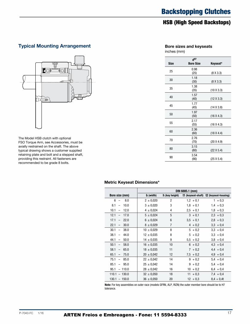
Typical Mounting Arrangement
The Model HSB clutch with optional FSO Torque Arm, see Accessories, must be axially restrained on the shaft. The above typical drawing shows a customer supplied retaining plate and bolt and a stepped shaft, providing this restraint. All fasteners are recommended to be grade 8 bolts.
Bore sizes and keyseats inches (mm)
dH7 Size Bore Size Keyseat*
250.98
(25) (8 X 3.3)
301.18
(30) (8 X 3.3)
351.38
(35) (10 X 3.3)
401.57
(40) (12 X 3.3)
451.77
(45) (14 X 3.8)
501.97
(50) (16 X 4.3)
552.17
(55) (16 X 4.3)
602.36
(60) (18 X 4.4)
702.76
(70) (20 X 4.9)
803.15
(80) (22 X 5.4)
903.54
(90) (25 X 5.4)
DIN 6885.1 (mm)Bore size (mm) b (width) h (key height) t1 (keyseat-shaft) t2 (keyseat-housing)
6 – 8.0 2 ± 0,020 2 1,2 + 0,1 1 + 0,3
8.1 – 10.0 3 ± 0,020 3 1,8 + 0,1 1,4 + 0,3
10.1 – 12.0 4 ± 0,024 4 2,5 + 0,1 1,8 + 0,3
12.1 – 17.0 5 ± 0,024 5 3 + 0,1 2,3 + 0,3
17.1 – 22.0 6 ± 0,024 6 3,5 + 0,1 2,8 + 0,3
22.1 – 30.0 8 ± 0,029 7 4 + 0,2 3,3 + 0,4
30.1 – 38.0 10 ± 0,029 8 5 + 0,2 3,3 + 0,4
38.1 – 44.0 12 ± 0,035 8 5 + 0,2 3,3 + 0,4
44.1 – 50.0 14 ± 0,035 9 5,5 + 0,2 3,8 + 0,4
50.1 – 58.0 16 ± 0,035 10 6 + 0,2 4,3 + 0,4
58.1 – 65.0 18 ± 0,035 11 7 + 0,2 4,4 + 0,4
65.1 – 75.0 20 ± 0,042 12 7,5 + 0,2 4,9 + 0,4
75.1 – 85.0 22 ± 0,042 14 9 + 0,2 5,4 + 0,4
85.1 – 95.0 25 ± 0,042 14 9 + 0,2 5,4 + 0,4
95.1 – 110.0 28 ± 0,042 16 10 + 0,2 6,4 + 0,4
110.1 – 130.0 32 ± 0,050 18 11 + 0,3 7,4 + 0,4
130.1 – 150.0 36 ± 0,050 20 12 + 0,3 8,4 + 0,4t
Note: For key assemblies on outer race (models GFRN, ALP, RIZN) the outer member bore should be to H7 tolerance.
Metric Keyseat Dimensions*
ARTEN Freios e Embreagens - Fone: 11 5594-8333

18 P-7043-FC 1/16
Backstopping ClutchesHSB (High Speed Backstops)
J Size A B C D E F G H Number Thread Depth K *L*
4004.78 2.75 3.500/3.498 2.69 .06 x 45° 1.19 .03 2.88
4 @ 90° .312-24 .50
.250-28 45° (121.44) (69.85) (88.90/88.85) (68.25) (1.57 x 45°) (29.97) (.78) (73.02) (12.70)
5006.50 3.50 4.250/4.248 3.38 .06 x 45° 1.19 .06 3.63
4 @ 90° .312-24 .63
.250-28 45° (165.10) (88.90) (107.95/107.90) (85.72) (1.57 x 45°) (30.15) (1.57) (92.07) (15.87)
6006.75 3.75 5.375/5.373 3.63 .06 x 45° 1.75 .06 4.75
6 @ 60° .312-24 .63
.250-28 30° (171.45) (95.25) (136.52/136.47) (92.07) (1.57 x 45°) (44.45) (1.57) (120.65) (15.87)
7009.00 5.00 7.125/7.123 4.88 .06 x 45° 3.56 .06 6.25
8** .375-24 .75
.250-28 0° or 30° (228.60) (127.00) (180.97/180.92) (123.82) (1.57 x 45°) (90.42) (1.57) (158.75) (19.05)
75011.00 6.00 8.750/8.748 5.88 .06 x 45° 4.25 .06 7.00
8** .500-20 1.00
.500-20 0° or 30° (279.40) (152.40) (222.25/222.20) (149.22) (1.57 x 45°) (107.95) (1.57) (177.80) (25.40)
80011.50 6.00 10.000/9.998 5.88 .06 x 45° 5.50 .06 8.94
8 @ 45° .500-20 1.00
.500-20 0° or 45° (292.10) (152.40) (254.00/253.95) (149.22) (1.57 x 45°) (139.70) (1.57) (227.00) (25.40)
90012.25 6.38 12.000/11.997 6.25 .06 x 45° 6.38 .06 9.75
10 @ 36° .625-18 1.25
.500-20 0° or 18° (311.15) (161.92) (304.80/304.72) (158.75) (1.57 x 45°) (161.92) (1.57) (247.65) (31.75)
102712.68 6.63 15.000/14.997 6.50 .13 x 45° 9.00 .06 11.75
12 @ 30° .625-18 1.00
.500-20 15° (322.07) (168.27) (381.00/380.92) (165.10) (3.17 x 45°) (228.60) (1.57) (298.45) (25.40)
* Angle-breather hole to mounting hole.
** Six holes equally spaced at 60° plus two extra holes at 180°. Six hardened mounting screws are adequate for torque loads up to 3,000 lb.ft. (4068 Nm) for model 700, or 5,100 lb.ft. (6916 Nm) for model 750; use eight hardened mounting screws for torque loads above these values.
Dimensions inches (mm)
D
KOil Holes
LAngle-Breather Hole
to Mounting Hole
.375-18 NPTFThread
Sight Gauge
AE
Chamfer
C HF
JG
B
ARTEN Freios e Embreagens - Fone: 11 5594-8333

P-7043-FC 1/16 19
Backstopping ClutchesHSB
Bore sizes and keyseats***† inches (mm)
Bore RangeSize Bore Size Keyseat Min. Max.
.500 1/8 x 1/16 (12.70) (3.17 x 1.57)
.625 .437 .875400
(15.87) 3/16 x 3/32 (11.10) (22.22).750 (4.75 x 2.36)
(19.05)
.875 3/16 x 1/16 (22.22) (4.75 x 1.57)
.875 3/16 x 3/32 (22.22) (4.75 x 2.36)
1.000 (25.40)
5001.125 1/4 x 1/8 .750 1.312
(28.57) (6.35 x 3.17) (19.05) (33.32)
1.250 (31.75)
1.312 1/4 x 3/32 (33.32) (6.35 x 2.36)
1.250 1/4 x 1/8 (31.75) (6.35 x 3.17)
1.375 (34.92)
1.500 .937 *2.250*600
(38.10) 3/8 x 3/16 (23.80) (57.15)1.625 (9.52 x 4.75)
(41.27)
1.750 (44.45)
2.000 3/8 x 1/8 (50.80) (9.52 x 3.17)
1.937 (49.20)
2.000 1/2 x 1/4 (50.80) (12.70 x 6.35)
2.250 (57.15)
7002.437 1.875 **3.250**
(61.90) 5/8 x 5/16 (47.62) (82.55)
2.500 (15.87 x 7.92) (63.50)
2.750 5/8 x 7/32 (69.85) (15.87 x 5.59)
2.937 5/8 x 1/8 (74.60) (15.87 x 3.17)
* 1/2 x 1/8 keyway
** 3/4 x 1/4 keyway
*** For finished dimensions of keys supplied with the clutch, contact Formsprag.
† For Bore Sizes/Shaft Tolerances, see page 42.
Bore RangeSize Bore Size Keyseat Min. Max.
2.437 (61.90)
2.500 5/8 x 5/16 (63.50) (15.87 x 7.92)
2.750 (69.85)
7502.937 2.250 3.437
(74.60) 3/4 x 3/8 (57.15) (87.30)
3.000 (19.05 x 9.52) (76.20)
3.250 3/4 x 3/16 (82.55) (19.05 x .635)
3.437 3/4 x 3/16 (87.30) (19.05 x 4.75)
3.000 (76.20) 3/4 x 3/83.250 (19.05 x 9.52)
(82.55)
3.437 (87.30)
3.500 7/8 x 7/16 (88.90) (22.22 x 11.10)
8003.750 2.625 4.437
(95.25) (66.67) (112.70)
3.937 (100.00) 1 x 1/2
4.000 (25.40 x 12.70) (101.60)
4.250 1 x 3/8 (107.95) (25.40 x 9.52)
4.437 1 x 1/4 (112.70) (25.40 x 6.35)
4.000 (101.60)
4.250 (107.95)
4.437 1 x 1/2 (112.70) (25.40 x 12.70)
4.500 (114.30)
9004.750 3.625 5.437
(120.65) (92.07) (138.10)
4.937 (125.40) 1 x 3/8
5.000 (25.40 x 9.52) (127.00)
5.250 (133.35) 1 x 1/4
5.437 (25.40 x 6.35) (138.10)
4.937 to 6.000 1 1/4 x 5/8 (125.40 to 152.40) (31.75 x 15.87)
10276.250 to .6.500 1 1/2 x 1/2 4.937 7.000
(158.75 to 165.10) (38.10 x 12.70) (125.40) (177.80)
6.750 to 7.000 1 1/2 x 7/16 (171.45 to 177.80) (38.10 x 11.10)
ARTEN Freios e Embreagens - Fone: 11 5594-8333

20 P-7043-FC 1/16
Holdback ClutchesLLH® (Long Life Holdbacks®)
Ball Bearings
Load Carrying Elements (Sprag)
Inner Race
Outer Race
Oil SealTorque Caps
Labyrinth Seal
Torque Arm
Quick Disconnect Mounting Pins
Backstopping Technology
Formsprag offers two technologies in backstopping designs, Sprag and Ramp & Roller. The sprag design is comprised of a full complement of accurately formed sprags filling the annular space. The ramp & roller design consists of precisionmachined ramps on the inner race and bearing quality cylindrical rollers filling the annular space.
In backstopping or holdback applications, one race is always fixed to a stationary ground member. The function of the holdback clutch is to permit rotation of the mechanism connected to the inner race in one direction only, and to prevent rotation in the reverse direction at any time. Although the clutch normally overruns most of the time, it is referred to as a holdback or backstop in conveyors, gear reducers and similar equipment, because its function is to prevent reverse rotation.
LLH holdback clutches are ready to install. They are equipped with a onepiece, quickly detachable torque arm (simply remove two pins), and grease labyrinth protected oil seals that positively prevent airborne contaminants from reaching internal seals and parts. Oil lubricated, the clutch assembly also includes an oil sight gauge with filter breather, for ease in checking lubricant level. These clutches are designed to be mounted on a through shaft, with the inner race driven by a key. Standard keys are supplied by Formsprag with all holdbacks at no additional charge.
Load Carrying Elements (Rollers)
Inner Race
Outer Race
Oil Seal Torque Arm
Quick Disconnect Mounting Pins
Torque CapsLabyrinth Seal
Sprag Design(Models LLH-700S through LLH-5000S)
Ramp and Roller Design(Models LLH-1250R through LLH-5500R)
Ball Bearing
ARTEN Freios e Embreagens - Fone: 11 5594-8333

P-7043-FC 1/16 21
Holdback ClutchesLLH® (Long Life Holdbacks®)
Bore Range Torque Maximum Resistance Available Shipping
Capacity Overrunning after run-in Min. Max. Weight lb.ft. Speed lb.ft. in. in. lb.
Size (Nm) RPM (Nm) (mm) (mm) (kg)
7005,000
4002.63 1.875 2.937 160
(6800) (3.57) (47.63) (74.60) (72)
7507,000
3803.75 2.250 3.437 215
(9520) (5.09) (57.15) (87.30) (97)
80013,000
3005.25 2.625 4.437 325
(17680) (7.12) (66.68) (112.70) (147)
90018,000
2506.25 3.625 5.437 570
(24480) (8.48) (92.08) (138.10) (258)
1027 27,000
20010 4.937 7.000 750
(36720) (13.56) (125.40) (177.80) (340)
1051 45,000
20012 4.937 7.000 800
(61200) (16.27) (125.40) (177.80) (363)
1250 65,000
17015 6.750 9.000 1,400
(88400) (20.34) (171.45) (228.60) (633)
1300 90,000
14028 7.937 10.000 1,700
(122400) (37.97) (201.60) (254.00) (770)
1375 135,000
13039 8.937 11.000 2,200
(183600) (52.87) (227.00) (279.40) (995)
2000 200,000
10080 10.937 13.250 3,200
(272000) (108.48) (277.80) (336.55) (1452)
2400 265,000
85100 13.000 15.500 4,200
(360400) (135.60) (330.20) (393.70) (1905)
3500 375,000
80120 13.437 20.000 5,850
(510000) (162.72) (341.30) (508.00) (2653)
5000 700,000
75125 13.437 20.000 5,930
(952000) (169.50) (341.30) (508.00) (2690)
Specifications Typical Holdback Specifications
1. Holdbacks installed on elevatorsand inclined conveyors musthave adequate torque capacity toprevent runback, and must complywith the holdback manufacturer’srecommended practice in theselection and application of a safesize.
2. The sprags within the holdbackmust be positioned and individuallyenergized within a suitable retainer.Sprags must act independent ofthe retainer and independent of theaction of any other sprag.
3. The sprags and the bearings withinthe holdback must be lubricatedwith lubricant suitable for theapplicable extremes of ambienttemperatures. The lubricationsystem must incorporate atransparent area suitable forvisual checking of the oil levelat approximately the level of thecenterline of the shaft, suitablefitting for draining oil from theholdback, means for filling theholdback with oil, and a breatherto relieve pressure within theholdback. The breather must beequipped with a renewable filterarranged to prevent entry of foreignmatter into the lubrication system.The breather and filter may beincor por ated into the oil fillingfitting. An oil seal must be installedexternally of each bearing.
4. For dusty or abrasive atmospheresthe holdbacks must be equippedwith a greasefilled labyrinth sealexternal to each oil seal.A sufficient number of greasefittings must be provided to insurecomplete filling and purging of thelabyrinth.
5. The holdback must be symmetricalto permit field installation for eitherdirection of rotation withoutdisassembly of the sealedholdback assembly.
6. The holdback must be equippedwith torque arm securely fastenedto the outer race of the clutch. Theouter end of the torque arm mustbe re strained by means that allowthe arm to float while preventingrotation of the outer race.
7. The torque and speed capacityspecified by the holdbackmanufacturer must be based uponadequate tests and engineeringdocumentation. Since these unitsare used as safety devices, anadequate design safety factor mustbe used. The compressive stressused in the Hertz stress equationswill not exceed 450,000 psi.
8. Load carrying elements in theholdbacks will preferably bemanufactured from steel forgings,extrusions or bar stock.
9. To assure that proper heattreatment has been given to theholdback parts, relative tohardness, case depth andmicrostructure, a certificate ofquality attesting to propermetallurgical examination of theabove mentioned items by theholdback manufacturer’slaboratory will be provided to the purchaser.
ARTEN Freios e Embreagens - Fone: 11 5594-8333

22 P-7043-FC 1/16
Holdback ClutchesLLHApplication Information
Typical Conveyor Holdback Arrangements
Formsprag Long Life Holdbacks are designed to “holdback” reverse torque. They are commonly used on inclined conveyors, bucket elevators, or pumps. Holdbacks have also been used on people moving systems, such as ski lifts and elevators. Specially designed nuclear holdbacks are currently installed on vertical shaft applications in several nuclear power plants with a required 40year life.
Torque Arm Mounting Positions — With standard oil sight gauges, the preferred torque arm mounting position is
approximately horizontal or slightly off of vertical. For installations requiring torque arms oriented in some other position, consult Formsprag.
Axial Retention Collars — Formsprag recommends that holdbacks be axially restrained on the shaft. The preferred method of accomplishing this is with set collars (see page 36). Any type of axial restraint applied to the torque arm reaction end will result in uneven bearing loads that will greatly reduce the bearing B10 life. Restraint keys are also available. See page 37.
Single Head Pulley DriveLocate the holdback on the opposite end of the head pulley drive shaft from the drive motor, speed reducer and coupling.
There are two rules for selecting holdbacks:
1. The holdback should always be mounted on the drive shaft.
2. The torque capacity of the holdback should be equal toor greater than the rated capacity of the drive motor.
Single Drive Pulley Other Than Head PulleyLocate the holdback on the drive pulley shaft, at the opposite end from the drive motor, speed reducer and coupling.
There are two rules for selecting holdbacks:
1. The holdback should always be mounted on the drive shaft.
2. The torque capacity of the holdback should be equal toor greater than the rated capacity of the drive motor.
ARTEN Freios e Embreagens - Fone: 11 5594-8333

P-7043-FC 1/16 23
Tandem Drive PulleysContact Formsprag for selection information on other possible holdback mounting arrangements.
Auxiliary Seals — All Formsprag holdbacks are furnished with two grease labyrinthtype seals. These seals, when purged with fresh grease periodically in accordance with our maintenance instructions, will protect the clutch against dusty or abrasive environments.
Operating Temperatures — For temperatures above 200°F consult Formsprag.
Standard Supplied Keys — All holdbacks are furnished with a hardened (25 – 40Rc) key. Customers should check key and
shaft stress before making final clutch selection since this may determine the maximum allowable drive torque capacity. Do not drive or pressfit the key. It should be installed in the shaft keyway with a “push” fit.
Extended Storage — If holdbacks are kept out of operation for six months or more, they should be flushed out and relubricated prior to operation. If holdbacks are to be stored over an extended period of time, consult Formsprag for specific preservation and packaging instructions. See page 33 for extended storage.
Single Pulley With Dual DriveContact Formsprag for selection information on other possible holdback mounting arrangements.
Holdback ClutchesLLH
ARTEN Freios e Embreagens - Fone: 11 5594-8333

24 P-7043-FC 1/16
Holdback ClutchesLLHModel sizes 700 through 900
Size A B C F G H J L M N P
33.63 30.00 18.00 8.25 7.13 6.38 5.00 3.63 5.31 3.88 2.50 700 (854.07) (762.00) (457.20) (209.55) (180.97) (161.92) (127.00) (92.07) (134.92) (98.42) (63.50)
36.38 32.00 20.38 9.25 8.38 7.38 6.00 4.63 5.81 3.88 2.50 750 (923.92) (812.80) (517.52) (234.95) (212.72) (187.32) (152.40) (117.47) (147.62) (98.42) (63.50)
37.00 32.00 22.13 9.50 8.63 7.63 6.00 5.44 7.31 4.19 2.75 800 (939.80) (812.80) (561.97) (241.30) (219.07) (193.67) (152.40) (138.10) (185.72) (106.35) (69.85)
50.00 44.00 22.75 9.75 9.25 8.00 6.38 6.44 8.56 4.69 3.25 900 (1270.00) (1117.60) (577.85) (247.65) (234.95) (203.20) (161.92) (163.50) (217.47) (119.05) (82.55)
* Model 700 through 900, pins are on centerline of torque arm.
U C
T
V
M
R
A
S
1/2"Min.
U C
T
V
A
12.010.0S
M
Horizontal Mounting
Sizes 700 through 800
Size 900
Dimensions inches (mm)
ARTEN Freios e Embreagens - Fone: 11 5594-8333

P-7043-FC 1/16 25
Holdback ClutchesLLH
Bore sizes and keyseats*† inches (mm)
Dimensions inches (mm)
Size Q R S T U V
1.00 7.00 7.13 6.00 6.00 5.00 700 (25.40) (177.80) (180.97) (152.40) (152.40) (127.00)
1.00 8.00 8.00 11.50 7.25 7.25 750 (25.40) (203.20) (203.20) (292.10) (184.15) (184.15)
1.00 10.00 10.00 12.50 8.00 7.75 800 (25.40) (254.00) (254.00) (317.50) (203.20) (196.85)
1.50 10.00 12.00 13.50 9.25 8.75 900 (38.10) (254.00) (304.80) (342.90) (234.95) (222.25)
Bore RangeSize Bore Size Keyseat Min. Max.
1.937 49.20)
2.000 1/2 x 1/4 (50.80) (12.70 x 6.35)
2.250 (57.15)
7002.437
5/8 x 5/16(61.90) (15.87 x 7.93)2.500
(63.50)
2.750 5/8 x 7/32 (69.85) (15.87 x 5.56)
2.937 5/8 x 1/8 (74.60) (15.87 x 3.18)
2.437 61.90)
2.500 5/8 x 5/16 (63.50) (15.87 x 7.93)
2.750 (69.85)
7502.937
(74.60)
3.000 3/4 x 3/8
(76.20)
(19.05 x 9.52)
3.250 3/4 x 1/4 (82.55) (19.05 x 6.35)
3.437 3/4 x 3/16 (87.30) (19.05 x 4.75)
2.937 (74.60)
3.000 3/4 x 3/8 (76.20) (19.05 x 9.52)
3.250 (82.55)
3.437 (87.30)
3.500 7/8 x 7/16 (88.90) (22.22 x 11.10)
8003.750
(95.25)
3.937 (100.00)
4.000 1 x 1/2
(101.60)
(25.40 x 12.70)
4.250 1 x 3/8 (107.95) (25.40 x 9.52)
4.437 1 x 1/4 (112.70) (25.40 x 6.35)
3.937 (100.00)
4.000 (101.60)
4.250 (107.95)
4.437 1 x 1/2
(112.70)
(25.40 x 12.70)
4.500 (114.30)
9004.750
(120.65)
4.937 (125.40)
5.000 1 x 3/8
(127.00)
(25.40 x 9.52)
5.250 (133.35)
5.437 1 x 1/4
(138.10)
(25.40 x 6.35)
*†
For finished dimensions of keys supplied with the clutch, contact Formsprag.
T For Bore Sizes/Shaft Tolerances, see page 34.
F
GH
B
L
QPN
1"Min.
1"Min.
JC
Sizes 700 through 900
1.875 (47.62)
3.250 (74.60)
2.250 (57.15)
3.437 (87.30)
2.625 (66.67)
4.437 (112.70)
3.625 (92.07)
5.437 (138.10)
ARTEN Freios e Embreagens - Fone: 11 5594-8333

26 P-7043-FC 1/16
Holdback ClutchesLLHModel Sizes 1027 Through 5000
Size A B C F G H J K L M N
68.63 61.88 18.00 9.63 9.50 8.25 6.63 — 8.88 10.75 10.00 1027 (1743.55) (1571.62) (457.20) (244.47) (241.30) (209.55) (168.27) — (225.42) (273.05) (254.00)
68.63 61.13 18.00 14.25 10.75 9.50 9.63 0.06 8.63 9.63 11.88 1051 (1743.07) (1552.57) (457.20) (361.95) (273.05) (241.30) (244.47) (1.57) (219.07) (244.47) (301.62)
76.00 66.00 20.25 14.97 11.57 9.80 10.25 .23 10.56 12.00 12.00 1250 (1930.40) (1676.40) (514.36) (380.24) (293.88) (248.92) (260.35) (5.84) (268.22) (304.80) (304.80)
77.75 67.00 21.81 15.10 11.87 9.80 10.25 .23 11.72 13.00 12.00 1300 (1974.85) (1701.80) (553.97) (383.54) (300.23) (248.92) (260.35) (5.84) (297.69) (330.20) (304.80)
82.25 70.00 24.50 15.22 12.07 9.80 11.00 .61 13.56 15.00 12.00 1375 (2089.15) (1778.00) (622.30) (386.59) (306.58) (248.92) (279.40) (15.494) (344.42) (381.00) (304.80)
97.00 82.00 29.44 15.38 12.38 10.38 10.62 0.13 17.56 19.25 13.00 2000 (2463.80) (2082.80) (747.70) (390.52) (314.32) (263.52) (269.8) (3.17) (446.07) (488.95) (330.20)
100.50 82.50 34.19 15.38 12.38 10.63 10.88 0.13 19.56 21.25 13.25 2400 (2552.70) (2095.50) (868.35) (390.52) (314.32) (269.87) (276.22) (3.17) (496.87) (539.75) (336.55)
101.50 82.50 34.12 20.16 17.00 14.75 18.00 1.03 22.46 26.00 16.75 3500 (2578.10) (2095.50) (866.65) (512.06) (431.80) (374.65) (457.20) (26.16) (570.48) (660.40) (425.45)
101.50 82.50 34.12 24.66 21.50 19.25 22.81 1.03 22.46 26.00 21.25 5000 (2578.10) (2095.50) (866.65) (626.36) (546.10) (488.95) (579.37) (26.16) (570.48) (660.40) (539.75)
F G H
L
KB
NQ
1 1/2"Min.C
1 1/2"Min.
A
J
Horizontal Mounting
S
T
1"Min.
Dimensions inches (mm)
ARTEN Freios e Embreagens - Fone: 11 5594-8333

P-7043-FC 1/16 27
Holdback ClutchesLLH
R1"
T
S
M
A
B
4.937 (125.40)
7.000 (177.80)
6.750 (171.45)
9.000 (228.60)
7.937 (201.60)
10.000 (254.00)
8.937 (227.00)
11.000 (279.40)
10.937 (277.80)
13.250 (336.55)
13.000 (330.20)
15.500 (393.70)
13.437 (341.30)
20.00 (508.00)
13.437 (341.30)
20.00 (508.00)
Vertical Mounting(Must be mounted at least 10° off of vertical)
4.937 (125.40)
7.000 (177.80)
Bore sizes and keyseats**† inches (mm)
Size P* Q R S T
1027 8.25 5.25 12.00 15.00 14.50
(209.55) (133.35) (304.80) (381.00) (368.30)
1051 9.50 5.25 12.00 15.00 12.00
(241.30) (133.35) (304.80) (381.00) (304.80)
1250 — 5.50 15.00 20.00 13.17
— (139.70) (381.00) (508.00) (334.52)
1300 — 6.25 18.00 21.50 13.42
— (158.75) (457.20) (546.10) (340.87)
1375 — 6.25 18.00 24.50 14.55
— (158.75) (457.20) (622.30) (369.57)
2000 — 7.13 24.00 30.00 17.25
— (180.97) (609.60) (762.00) (438.15)
2400 — 7.88 24.00 36.00 18.75
— (200.02) (609.60) (914.40) (476.25)
3500 — 8.00 24.00 38.00 20.17
— (203.20) (609.670) (965.20) (512.32)
5000 — 8.00 24.00 38.00 20.17
— (203.20) (609.60) (965.20) (512.32)
* Width over torque cap, see page 25.
Dimensions inches (mm)
Bore Range Size Bore Size Keyseat Min. Max.
4.937 (125.40) to 1 1/4 x 5/8 (31.75 x 15.87)
6.000 (152.40)6.250 (158.75)
1027 to 1 1/2 x 1/2 (38.10 x 12.70) 6.500 (165.10)6.750 (171.45)
to 1 1/2 x 7/16 (38.10 x 11.10) 7.000 (177.80)5.000 (127.00)
to 1 1/4 x 5/8 (31.75 x 15.88) 6.000 (152.40) 6.250 (158.75)
to 1 1/2 x 5/8 (38.10 x 15.88) 1051 6.625 (162.28)
6.750 (171.45) to 1 1/2 x 1/2 (38.10 x 12.70)
6.875 (174.63) 7.000 (177.80) 1 1/2 x 7/16 (38.10 x 11.11)7.50 (190.50)
to 1 3/4 x 7/8 (44.45 x 22.35) 7.937 (201.60) 8.000 (203.20)
1250 to 1 3/4 x 5/8 (44.45 x 16.00) 8.250 (209.55) 8.312 (211.12)
to 1 1/2 x 1/2 (38.10 x 12.70) 9.000 (228.60) 8.000 (203.20)
to 1 3/4 x 7/8 (44.45 x 22.35) 9.000 (228.60)
13009.063 (230.20)
to 1 1/2 x 1/2 (38.10 x 12.70) 10.000 (254.00)
9.000 (228.60) to 1 3/4 x 7/8 (44.45 x 22.35)
10.250 (260.35) 1375
10.312 (261.93) to 2 x 3/4 (50.80 x 19.05)
11.00 (279.40) 10.937 (277.80)
to 2 1/2 x 1 1/4 (63.50 x 31.75) 12.000 (304.80)
200012.063 (306.40)
to 2 1/2 x 1 (63.50 x 25.40) 13.250 (336.55) 13.000 (330.20)
to 2 1/2 x 1 1/4 (63.50 x 31.75) 15.000 (381.00)
240015.063 (382.60)
to 2 1/2 x 1 (63.50 x 25.40) 15.500 (393.70) 13.437 (341.30)
to 2 1/2 x 1 1/4 (63.50 x 31.75) 13.750 (349.25)
3500 14.000 (355.60) to 3 x 1 1/2 (76.20 x 38.10)
18.000 (457.20) 20.000 (508.00) 3 x 1 1/4 (76.20 x 31.75)13.437 (341.30)
to 2 1/2 x 1 1/4 (63.50 x 31.75) 13.750 (349.25)
5000 14.000 (355.60) to 3 x 1 1/2 (76.20 x 38.10)
18.000 (457.20) 20.000 (508.00) 3 x 1 1/4 (76.20 x 31.75)
** For finished dimensions of keys supplied with the clutch, contact Formsprag.† For Bore Sizes/Shaft Tolerances, see page 34.
ARTEN Freios e Embreagens - Fone: 11 5594-8333

28 P-7043-FC 1/16
Holdback ClutchesLLHModel Sizes 1250R Through 5500R
Model Torque Maximum Overrunning Shipping No. Capacity Speed A B C F J Weight
1250R63,000
12087.44 77.95 12.25 9.3 9.3 830
(85909) (2221) (1980) (311) (236) (236) (381)
1300R90,000
10591.89 81.89 14.25 10.5 10.5 1,130
(122040) (2334) (2080) (362) (267) (267) (520)
1375R135,000
9099.61 87.99 16.06 11.75 11.75 1,500
(183060) (2530) (2235) (408) (298) (298) (690)
2000R180,000
80107.72 94.09 16.54 12.6 12.6 2,100
(244407) (2736) (2390) (420) (320) (320) (966)
2400R240,000
70115.16 100.00 18.0 16.0 16.0 2,700
(325,396) (2925) (2540) (457) (406) (406) (1242)
3500R375,000
60138.89 120.00 23.0 18.75 18.7 6,000
(508432) (3528) (3048) (584) (476) (476) (2760)
5000R540,000
60166 144 26.50 22.5 22.5 9,000
(732142) (4216) (3658) (673) (572) (572) (4140)
5500R720,000
60166 144 26.50 23.5 23.5 10,000
(976271) (4216) (3658) (673) (597) (597) (4545)
Dimensions inches (mm)
* Torque arm I-beam. S-type section dimensions may vary according to the American Iron and Steel Institute or DIN standards.
F
SR
QJ
B
C
A
F
SR
QJ
B
C
A
ARTEN Freios e Embreagens - Fone: 11 5594-8333

P-7043-FC 1/16 29
Holdback ClutchesLLH
5.25(133.35)
8.000(203.2)
5.75(146.05)
9.000(230.00)
6.75(171.45)
10.500(270.00)
7.25(184.15)
11.75(298.45)
8.25(209.55)
14.000(360.00)
10.25(260.35)
18.00(457.20)
15.25(387.35)
21.00(533.40)
Bore sizes and keyseats**† inches (mm)
Dimensions inches (mm)
Model Bore Bore Range
No. Size Keyseat Min. Max.
6.000 (152.00)to 1.500 x .75 (38.10 x 19.05)
6.500 (165.10)
6.563 (166.70) to 1.750 x .75 (44.45 x 15.88) 1250R 7.500 (190.50)
7.563 (192.10)to 2.000 x .75 (50.80 x 19.05)
8.250 (209.55)
6.500 (165.10) 1.500 x .75 (38.10 x 12.70)
6.563 (166.70)to
7.500 (190.50) 1.750 x .75 (44.45 x 19.05)
1300R
7.563 (192.10)to
8.750 (222.25) 2.000 x .75 (50.80 x 19.05)
7.750 (196.85)to
9.000 (228.60) 2.000 x .75 (50.80 x 19.05)
1375R9.063 (230.20)
to10.250 (260.35)
2.500 x .88 (63.50 x 22.23)
9.000 (228.60) 2.000 x .75 (50.80 x 19.05)
9.063 (230.20)to
2000R 11.000 (279.40)
2.500 x .88 (63.50 x 22.23)
11.063 (281.00)to
12.000 (304.80) .000 x 1.00 (76.20 x 25.40)
10.500 (266.70)
to11.000 (279.40)
2.500 x .88 (63.50 x 22.23)
2400R
11.063 (281.00)to
13.000 (330.20) 3.000 x 1.00 (76.20 x 25.40)
13.063 (331.80)to
13.750 (249.25) 3.500 x 1.25 (88.90 x 31.75)
13.000 (330.20) 3.000 x 1.00 (76.20 x 25.40)
13.063 (331.80)to 3.500 x 1.25 (88.90 x 31.75)
3500R 15.000 (381.00)
15.063 (382.60)to 4.000 x 1.50 (101.60 x 38.10)
17.000 (431.80)
13.000 (330.20) 3.000 x 1.00 (76.20 x 25.40)
13.063 (331.80)
to 3.500 x 1.25 (88.90 x 31.75)
15.000 (381.00)
15.063 (382.60)
5000Rto 4.000 x 1.50 (101.60 x 38.10)
and 18.000 (457.20)
5500R 18.063 (458.80)
to 5.000 x 1.75 (127.00 x 44.45)
22.000 (558.80)
22.063 (560.40)to
21.000 (533.4) 6.000 x 4.00 (152.40 x 101.60)
** For finished dimensions of keys supplied with the clutch, contact Formsprag.† For Bore Sizes/Shaft Tolerances, see page 34.
Model No. Q* R* S
1250R5.00 10.00 19.6 (127) (254) (489)
1300R5.51 12.01 23.0 (140) (305) (584)
1375R5.62 15.00 25.7 (143) (381) (653)
2000R6.26 18.00 30.3 (159) (457) (770)
2400R6.38 20.00 34.5 (162) (508) (876)
3500R8.00 24.20 41.0 (203) (615) (1041)
5000R 10.12 27.20 47.0
(257) (691) (1194)
5500R 10.12 27.20 47.0
(257) (691) (1194)
ARTEN Freios e Embreagens - Fone: 11 5594-8333

30 P-7043-FC 1/16
Holdback ClutchesLLHSelection Procedure
ConveyorsThere are basically two ways to size conveyor backstops or holdbacks, either according to CEMA (Conveyor Equipment Manufacturers Association) standards or based on motor breakdown/stall torque values. Formsprag recommends that the selection be made on whichever value is greater.
CEMA Formula:The CEMA formula allows the design engineer to consider friction as a partial aid in preventing reverse rotation, thus reducing the torque capacity required for the clutch. Selection by this method does require the use of a service factor (S.F.). The basic CEMA formula for design torque is:
(S.F.) (Lift HP 1/2 Friction HP) (5,250) Tcema (lb.ft.) =
(Headshaft RPM)
Formsprag recommends a minimum service factor of 1.5 when sizing with this formula. See worksheet, page 31.
Motor Breakdown or Stall Torque Formula:Motor breakdown or stall torque could be imposed on the backstop if the conveyor is jammed or frozen, or when the conveyor is overloaded. In this condition the motor will produce stall torque which is significantly higher than the motor nameplate rating. This will cause the belt to stretch; and when the motor stalls, the stall torque produced by the motor will be imposed on the backstop. This torque will be increased if there is a load on the belt. Therefore, the maximum loading on a backstop occurs in the rare case of a moving belt being gradually overloaded until the motor reaches stall or breakdown torque. The torque on the backstop will be the motor torque from the stretched belt plus the torque from the load moving in the reverse direction due to the force of gravity.
To select a holdback based on motor breakdown torque, calculate motor torque using the following formula:
(S.F.) (Motor Nameplate HP) (5,250) Tmotor (lb.ft.) =
(Headshaft RPM)
The clutch may be selected on the basis of installed nameplate horsepower without using a service factor (S.F.), provided the motor breakdown torque does not exceed 175 percent of the nameplate rating; a minimum service factor based upon the ratio of motor breakdown torque to 175 percent of nameplate torque is required in order to preclude serious damage to the installation or to the holdback.
Torque Limiting Device:If a torque limiting device is used and is less than 175 percent of the motor nameplate torque, then the holdback selected should have a capacity not less than 1.5 times the CEMA runback torque.
Bucket Elevators When selecting and sizing long life holdbacks application on bucket elevators, friction may or may not be considered because it is usually only a small fraction of the lift HP required. Similarly, motor breakdown HP is usually not considered if traction wheel drives are used because the elevator will usually slip before the breakdown HP is reached. For these reasons, the recommended design torque is based on lift HP alone.
(S.F.) (Lift HP) (5,250) TB (lb.ft.) =
(Headshaft RPM)
A minimum service factor (S.F.) of 2.0 is recommended. If additional assistance is needed, consult Formsprag Application Engineering.
ARTEN Freios e Embreagens - Fone: 11 5594-8333

P-7043-FC 1/16 31
Holdback ClutchesLLH
Material Weight (lb.ft.3)
Belt 30 lbs. 50 lbs. 75 lbs. 100 lbs. 130 lbs. 200 lbs. Width F C F C F C F C F C F C (Ratio)
18”.017 .050 .017 .050 .018 .050 .018 .050 .018 .050 .020 .037 .0 - .105
.015 .040 .015 .040 .016 .040 .016 .040 .018 .034 .020 .033 .105 - .310
24” .021 .050 .020 .043 .020 .045 .020 .041 .020 .045 .022 .037 .0 - .105
.020 .035 .019 .033 .019 .033 .020 .030 .020 .030 .020 .030 .105 - .310
30” .025 .044 .025 .043 .022 .037 .022 .041 .025 .038 .022 .037 .0 - .105
.024 .030 .025 .028 .022 .028 .023 .025 .025 .025 .025 .025 .105 - .310
36”.030 .040 .030 .038 .030 .037 .030 .038 .032 .038 .030 .039 .0 - .105
.027 .030 .027 .030 .027 .030 .027 .030 .032 .029 .030 .023 .105 - .310
42”.030 .040 .036 .036 .030 .040 .030 .040 .036 .040 .038 .040 .0 - .105
.031 .030 .031 .030 .035 .027 .036 .027 .036 .027 .038 .027 .105 - .310
48”.038 .036 .038 .038 .038 .039 .043 .038 .045 .040 .052 .044 .0 - .105
.038 .030 .038 .030 .040 .027 .043 .027 .043 .027 .052 .027. .105 - .310
54”.040 .037 .040 .040 .045 .042 .046 .042 .050 .047 — — .0 - .105
.040 .030 .041 .028 .047 .028 .051 .028 .051 .030 — — .105 - .310
60”.042 .037 .042 .040 .052 .045 .052 .049 — — — — .0 - .105
.042 .030 .042 .028 .052 .029 .052 .030 — — — — .105 - .310
Speed and Idler Factors
Conveyors under 500’ in lengthBased on:
Material Weight (W) Total Lift (H) Conveyor Length (L)
F = Speed factor for empty belt C = Idler factor for loaded belt
Factor used depends on H/L Ratio (Sine of Angle of Slope)
Worksheet—CEMA FormulaHoldback torque calculations are based on lift HP minus onehalf friction HP. Equations are condensed and constants are tabulated as shown above.
D
H
L
DataConveyor Length L = ___________ feet Belt Speed S = ___________ FPM Short Tons Per Hour W = ___________ TPH Total Lift H = ___________ feet Headshaft Pulley Diameter D = ___________ feet Belt Width = ___________ inches Material Weight = ___________ lb./ft.3 Speed Factor F = ___________ Idler Factor C = ___________ Service Factor = ___________
(1.5 minimum)
CalculationsEnter the data into these equations and perform the calculations following the sample worksheet.
(1) Power to lift load (P1):
P1 = WH = ( ) ( ) = HP 990 990
(2) Power to move empty belt and idlers (P2):
P2 = .5LSF = .5 ( ) ( ) ( ) = HP 1,000 1,000
(3) Power to move loaded belt (P3):
P3 = .5LWC = .5 ( ) ( ) ( ) = HP 990 990
(4) Total Holdback Power (HBP) = P1 – P2 – P3 = HBP
(5) Holdback Torque (Tcema) =(HPB) (πD) 5,250 x Service Factor
S
Tcema = ( ) ( ) ( 5,250 ) ( ) = lb.ft. ( )
HL
ARTEN Freios e Embreagens - Fone: 11 5594-8333

32 P-7043-FC 1/16
Holdback ClutchesLLH
Torque Arm InstallationThe torque arm reaction force is the force which the torque arm stops must resist. Formsprag recommends that the stops be at least 3/4 of the distance (B) away from the center line of the clutch.
Models 1027 thru 5000
1"2
1" 1"
Models 700 thru 900
Torque Arm ClearanceTorque arm clearance is required on all sides of the torque arm to prevent binding which could cause uneven loading of the holdback bearings.
Note: The torque arm must not be rigidly fastened at reaction point.
The torque arm reaction force is calculated as follows:
Torque Arm Reaction—lbs. (kg) = *Rated Backstopping Torque—lb.ft. (Nm)
Distance (.75B) of stop from centerline—ft. (m)
Note: Do not restrict torque arm movement in the axial direction.
* Ratings are shown on page 21of catalog for applicable holdback.
1 1"2
1 1"2
1"
STOP
STOP
B
Specifications
B .75B Catalog Torque Values Torque Arm Reaction ft. ft. lb.ft. lb.
Size (m) (m) (Nm) (kg)
700S2.5 1.88 4,000 2,150
(.76) (.57) (5424) (975)
750S2.67 2.00 6,800 3,400
(.81) (.61) (9221) (1542)
800S2.67 2.00 11,500 5,750
(.81) (.61) (15594) (2608)
900S3.67 2.75 18,000 6,550
(1.12) (.84) (24408) (2970)
1027S5.16 3.87 27,000 7,000
(1.57) (1.18) (36612) (3175)
1051S5.09 3.82 45,000 12,000
(1.55) (1.16) (61020) (5443)
1250S5.50 4.13 65,000 15,750
(1.68) (1.26) (88140) (7145)
1250R6.5 4.87 63,000 12,936
(1.98) (1.48) (85417) (7145)
1300S5.58 4.19 90,000 21,500
(1.71) (1.28) (122040) (9750)
1300R6.8 5.1 90,000 17,647
(2.0) (1.5) (122040) (9750)
1375S5.83 4.38 135,000 31,000
(1.78) (1.34) (183060) (14060)
1375R7.3 5.4 135,000 25,000
(2.2) (1.65) (183060) (14060)
2000S6.83 5.12 200,000 39,500
(2.08) (1.56) (271200) (17917)
2000R7.5 5.85 180,000 30,770
(2.3) (1.72) (244047) (17917)
2400S6.88 5.16 265,000 51,500
(2.10) (1.57) (359340) (23360)
2400R8.3 6.2 240,000 38,700
(2.5) (1.87) (325396) (23360)
3500S6.88 5.16 375,000 68,000
(2.10) (1.57) (508500) (30844)
3500R10 7.5 375,000 50,000
(3.0) (2.25) (508500) (30844)
5000S6.88 5.16 700,000 136,250
(2.10) (1.57) (949200) (61800)
5000R12 9 540,000 60,000
(3.6) (2.7) (732146) (27272)
5500R12 9 720,000 80,000
(3.6) (2.7) (976271) (36363)
ARTEN Freios e Embreagens - Fone: 11 5594-8333
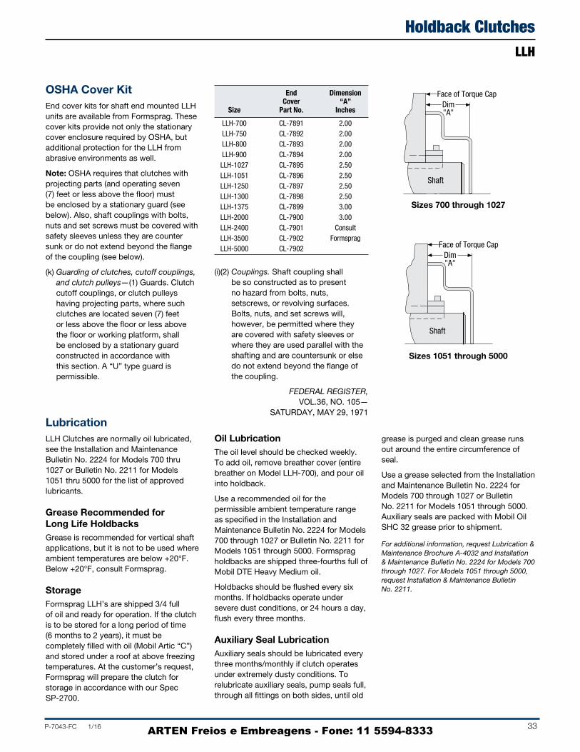
P-7043-FC 1/16 33
Holdback ClutchesLLH
End Dimension Cover “A”
Size Part No. Inches
LLH-700 CL-7891 2.00 LLH-750 CL-7892 2.00 LLH-800 CL-7893 2.00 LLH-900 CL-7894 2.00 LLH-1027 CL-7895 2.50 LLH-1051 CL-7896 2.50 LLH-1250 CL-7897 2.50 LLH-1300 CL-7898 2.50 LLH-1375 CL-7899 3.00 LLH-2000 CL-7900 3.00 LLH-2400 CL-7901 Consult LLH-3500 CL-7902 Formsprag LLH-5000 CL-7902
OSHA Cover KitEnd cover kits for shaft end mounted LLH units are available from Formsprag. These cover kits provide not only the stationary cover enclosure required by OSHA, but additional protection for the LLH from abrasive environments as well.
Note: OSHA requires that clutches with projecting parts (and operating seven (7) feet or less above the floor) mustbe enclosed by a stationary guard (seebelow). Also, shaft couplings with bolts,nuts and set screws must be covered withsafety sleeves unless they are countersunk or do not extend beyond the flangeof the coupling (see below).
(k) Guarding of clutches, cutoff couplings,and clutch pulleys—(1) Guards. Clutchcutoff couplings, or clutch pulleyshaving projecting parts, where suchclutches are located seven (7) feetor less above the floor or less abovethe floor or working platform, shallbe enclosed by a stationary guardconstructed in accordance withthis section. A “U” type guard ispermissible.
LubricationLLH Clutches are normally oil lubricated, see the Installation and Maintenance Bulletin No. 2224 for Models 700 thru 1027 or Bulletin No. 2211 for Models 1051 thru 5000 for the list of approved lubricants.
Grease Recommended for Long Life HoldbacksGrease is recommended for vertical shaft applications, but it is not to be used where ambient temperatures are below +20°F. Below +20°F, consult Formsprag.
StorageFormsprag LLH’s are shipped 3/4 full of oil and ready for operation. If the clutch is to be stored for a long period of time (6 months to 2 years), it must be completely filled with oil (Mobil Artic “C”) and stored under a roof at above freezing temperatures. At the customer’s request, Formsprag will prepare the clutch for storage in accordance with our Spec SP 2700.
Oil LubricationThe oil level should be checked weekly. To add oil, remove breather cover (entire breather on Model LLH700), and pour oil into holdback.
Use a recommended oil for the permissible ambient temperature range as specified in the Installation and Maintenance Bulletin No. 2224 for Models 700 through 1027 or Bulletin No. 2211 for Models 1051 through 5000. Formsprag holdbacks are shipped threefourths full of Mobil DTE Heavy Medium oil.
Holdbacks should be flushed every six months. If holdbacks operate under severe dust conditions, or 24 hours a day, flush every three months.
Auxiliary Seal LubricationAuxiliary seals should be lubricated every three months/monthly if clutch operates under extremely dusty conditions. To relubricate auxiliary seals, pump seals full, through all fittings on both sides, until old
grease is purged and clean grease runs out around the entire circumference of seal.
Use a grease selected from the Installation and Maintenance Bulletin No. 2224 for Models 700 through 1027 or Bulletin No. 2211 for Models 1051 through 5000. Auxiliary seals are packed with Mobil Oil SHC 32 grease prior to shipment.
For additional information, request Lubrication & Maintenance Brochure A-4032 and Installation & Maintenance Bulletin No. 2224 for Models 700 through 1027. For Models 1051 through 5000, request Installation & Maintenance Bulletin No. 2211.
(i)(2) Couplings. Shaft coupling shall be so constructed as to present no hazard from bolts, nuts, setscrews, or revolving surfaces. Bolts, nuts, and set screws will, however, be permitted where they are covered with safety sleeves or where they are used parallel with the shafting and are countersunk or else do not extend beyond the flange of the coupling.
FEDERAL REGISTER, VOL.36, NO. 105—
SATURDAY, MAY 29, 1971
Face of Torque CapDim"A"
Shaft
Face of Torque CapDim"A"
Shaft
Sizes 700 through 1027
Sizes 1051 through 5000
ARTEN Freios e Embreagens - Fone: 11 5594-8333
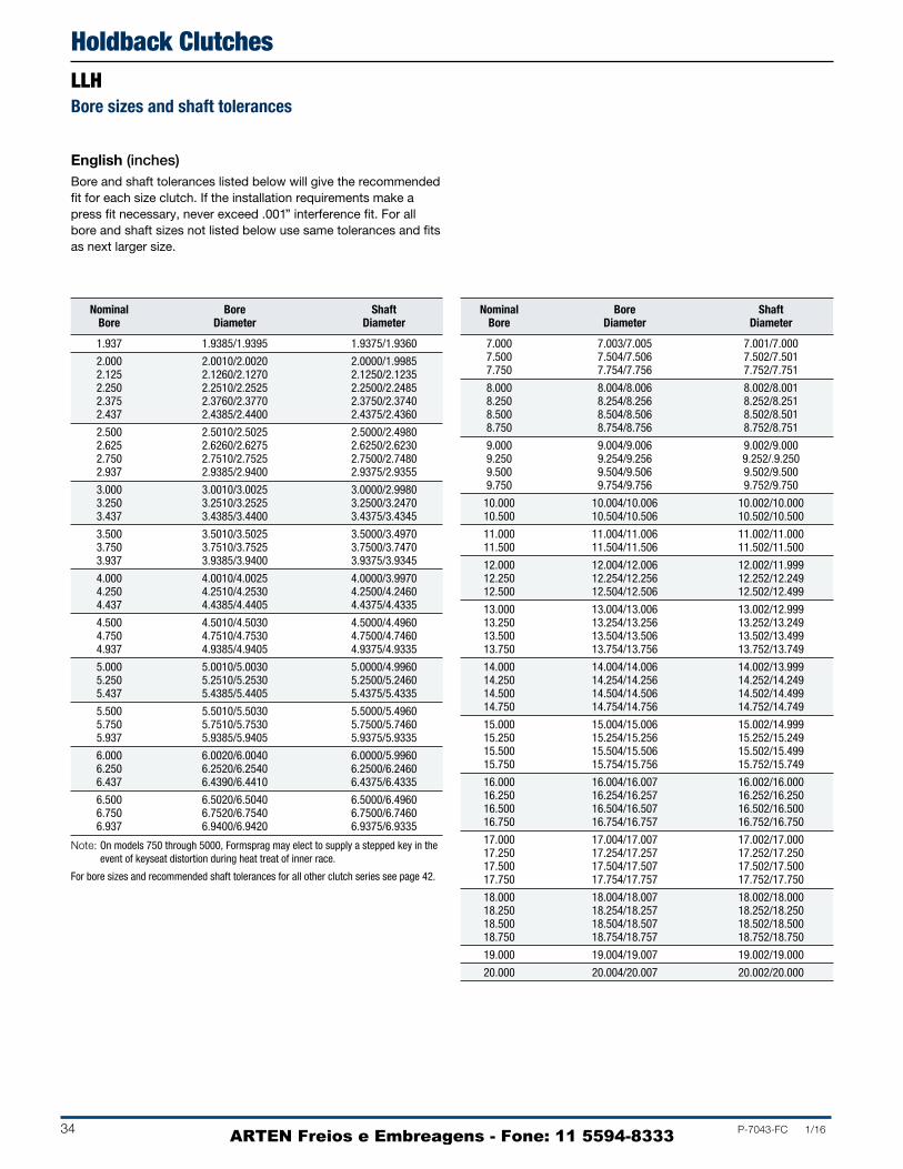
34 P-7043-FC 1/16
Holdback ClutchesLLHBore sizes and shaft tolerances
Nominal Bore Shaft Bore Diameter Diameter
1.937 1.9385/1.9395 1.9375/1.9360
2.000 2.0010/2.0020 2.0000/1.9985 2.125 2.1260/2.1270 2.1250/2.1235 2.250 2.2510/2.2525 2.2500/2.2485 2.375 2.3760/2.3770 2.3750/2.3740 2.437 2.4385/2.4400 2.4375/2.4360
2.500 2.5010/2.5025 2.5000/2.4980 2.625 2.6260/2.6275 2.6250/2.6230 2.750 2.7510/2.7525 2.7500/2.7480 2.937 2.9385/2.9400 2.9375/2.9355
3.000 3.0010/3.0025 3.0000/2.9980 3.250 3.2510/3.2525 3.2500/3.2470 3.437 3.4385/3.4400 3.4375/3.4345
3.500 3.5010/3.5025 3.5000/3.4970 3.750 3.7510/3.7525 3.7500/3.7470 3.937 3.9385/3.9400 3.9375/3.9345
4.000 4.0010/4.0025 4.0000/3.9970 4.250 4.2510/4.2530 4.2500/4.2460 4.437 4.4385/4.4405 4.4375/4.4335
4.500 4.5010/4.5030 4.5000/4.4960 4.750 4.7510/4.7530 4.7500/4.7460 4.937 4.9385/4.9405 4.9375/4.9335
5.000 5.0010/5.0030 5.0000/4.9960 5.250 5.2510/5.2530 5.2500/5.2460 5.437 5.4385/5.4405 5.4375/5.4335
5.500 5.5010/5.5030 5.5000/5.4960 5.750 5.7510/5.7530 5.7500/5.7460 5.937 5.9385/5.9405 5.9375/5.9335
6.000 6.0020/6.0040 6.0000/5.9960 6.250 6.2520/6.2540 6.2500/6.2460 6.437 6.4390/6.4410 6.4375/6.4335
6.500 6.5020/6.5040 6.5000/6.4960 6.750 6.7520/6.7540 6.7500/6.7460 6.937 6.9400/6.9420 6.9375/6.9335
Nominal Bore Shaft Bore Diameter Diameter
7.000 7.003/7.005 7.001/7.000 7.500 7.504/7.506 7.502/7.501 7.750 7.754/7.756 7.752/7.751
8.000 8.004/8.006 8.002/8.001 8.250 8.254/8.256 8.252/8.251 8.500 8.504/8.506 8.502/8.501 8.750 8.754/8.756 8.752/8.751
9.000 9.004/9.006 9.002/9.000 9.250 9.254/9.256 9.252/.9.250 9.500 9.504/9.506 9.502/9.500 9.750 9.754/9.756 9.752/9.750
10.000 10.004/10.006 10.002/10.000 10.500 10.504/10.506 10.502/10.500
11.000 11.004/11.006 11.002/11.000 11.500 11.504/11.506 11.502/11.500
12.000 12.004/12.006 12.002/11.999 12.250 12.254/12.256 12.252/12.249 12.500 12.504/12.506 12.502/12.499
13.000 13.004/13.006 13.002/12.999 13.250 13.254/13.256 13.252/13.249 13.500 13.504/13.506 13.502/13.499 13.750 13.754/13.756 13.752/13.749
14.000 14.004/14.006 14.002/13.999 14.250 14.254/14.256 14.252/14.249 14.500 14.504/14.506 14.502/14.499 14.750 14.754/14.756 14.752/14.749
15.000 15.004/15.006 15.002/14.999 15.250 15.254/15.256 15.252/15.249 15.500 15.504/15.506 15.502/15.499 15.750 15.754/15.756 15.752/15.749
16.000 16.004/16.007 16.002/16.000 16.250 16.254/16.257 16.252/16.250 16.500 16.504/16.507 16.502/16.500 16.750 16.754/16.757 16.752/16.750
17.000 17.004/17.007 17.002/17.000 17.250 17.254/17.257 17.252/17.250 17.500 17.504/17.507 17.502/17.500 17.750 17.754/17.757 17.752/17.750
18.000 18.004/18.007 18.002/18.000 18.250 18.254/18.257 18.252/18.250 18.500 18.504/18.507 18.502/18.500 18.750 18.754/18.757 18.752/18.750
19.000 19.004/19.007 19.002/19.000
20.000 20.004/20.007 20.002/20.000
English (inches)Bore and shaft tolerances listed below will give the recommended fit for each size clutch. If the installation requirements make a press fit necessary, never exceed .001” interference fit. For all bore and shaft sizes not listed below use same tolerances and fits as next larger size.
Note: On models 750 through 5000, Formsprag may elect to supply a stepped key in the event of keyseat distortion during heat treat of inner race.
For bore sizes and recommended shaft tolerances for all other clutch series see page 42.
ARTEN Freios e Embreagens - Fone: 11 5594-8333

P-7043-FC 1/16 35
Holdback ClutchesLLH
Nominal Bore Shaft Bore Diameter Diameter
49.20 49.24/49.26 49.21/49.17
50.80 50.83/50.85 50.80/50/76 53.98 54.00/54.03 53.97/53.94 57.15 57.18/57.21 57.15/57.11 61.90 61.94/61.98 61.91/61.87
63.50 63.53/63.56 63.50/63.45 66.68 66.70/66.74 66.68/66.62 69.85 69.88/69.91 69.85/69.80 74.60 74.64/74.68 74.61/74.56
76.20 76.23/76.26 76.20/76.15 82.55 82.58/82.61 82.55/82.47 87.30 87.34/87.38 87.31/87.24
88.90 88.92/88.96 88.90/88.82 95.25 95.28/95.31 95.25/95.17 100.00 100.04/100.08 100.01/99.94
101.60 101.63/101.66 101.60/101.52 107.95 107.98/108.03 107.95/107.88 112.70 112.74/112.79 112.71/112.61
114.30 114.33/114.38 114.30/114.20 120.65 120.68/120.73 120.65/120.55 125.40 124.44/125.49 125.43/125.31
127.00 127.03/127.08 127.00/126.90 133.35 133.38/133.43 133.35/133.25 138.10 138.14/138.19 138.11/138.01
139.70 139.72/139.78 139.70/139.60 146.05 146.08/146.13 146.05/145.95 150.80 150.84/150.89 150.81/150.71
152.40 152.45/152.50 152.40/152.30 158.75 158.80/158.85 158.75/158.65 163.50 163.55/163.60 163.51/163.41
165.10 165.15/165.20 165.10/164.10 171.45 171.50/171.55 171.45/171.35 176.20 176.28/176.33 176.21/176.11
Nominal Bore Shaft Bore Diameter Diameter
177.80 177.88/177.93 177.83/177.80 190.50 190.60/190.66 190.55/190.53 196.85 196.95/197.00 196.90/196.88
203.20 203.30/203.35 203.25/203.23 209.55 209.65/209.70 209.60/209.58 215.90 216.00/216.05 215.95/215.93 222.25 222.35/222.40 222.30/222.28
228.60 228.70/228.75 228.65/228.60 234.95 235.05/235.10 235.00/234.95 241.30 241.40/241.45 241.35/241.30 247.65 247.75/247.80 247.70/247.65
254.00 254.10/254.15 254.05/254.00 266.80 266.80/266.85 266.75/266.70
279.40 279.50/279.55 279.45/279.40 292.10 292.20/292.25 292.15/292.10
304.80 304.90/304.95 304.85/304.77 311.15 311.25/311.30 311.20/311.12 317.50 317.60/317.65 317.55/317.47
330.20 330.30/330.35 330.25/330.17 336.55 336.65/336.70 336.60/336.52 342.90 343.00/343.05 342.95/342.87 349.25 349.35/349.40 349.30/349.22
355.60 355.70/355.75 355.65/355.57 361.95 362.05/362.10 362.00/361.92 368.30 368.40/368.45 368.35/368.27 374.65 374.75/373.80 374.70/374.62
381.00 381.10/381.15 381.05/380.97 387.35 387.45/387.50 387.40/387.32 393.70 393.80/393.85 393.75/393.67 400.05 400.15/400.20 400.10/400.02
406.40 406.50/406.58 406.45/406.40 412.75 412.85/412.93 412.80/412.75 419.10 419.20/419.28 419.15/419.10 425.25 425.55/425.63 425.50/425.45
431.80 431.90/431.98 431.85/431.80 438.15 438.25/438.33 438.20/438.15 444.50 444.60/444.68 444.55/444.50 450.85 450.95/451.01 450.90/450.85
457.20 457.30/457.38 457.25/457.20 463.55 463.65/463.73 463.60/463.55 469.90 470.00/470.08 469.95/469.90 476.25 476.35/476.43 476.30/476.25
482.60 482.70/482.78 482.65/482.60
508.00 508.10/508.18 508.05/508.00
Metric (millimeters)Bore and shaft tolerances listed below will give the recommended fit for each size clutch. If the installation requirements make a press fit necessary, never exceed .025 mm interference fit. For all bore and shaft sizes not listed below use same tolerances and fits as next larger size.
For metric bores the recommended bore tolerances are F7.
Note: On models 750 thru 5000, Formsprag may elect to supply a stepped key in the event of keyseat distortion during heat treat of inner race.
For bore sizes and recommended shaft tolerances for all other clutch series see page 43.
ARTEN Freios e Embreagens - Fone: 11 5594-8333

36 P-7043-FC 1/16
Set Collars Set Collar
Snap Ring Shaft Shoulder Restraint Key
Retainer Plate
Axial RestraintFormsprag requires that all clutches and holdbacks be axially restrained when mounted. Our recommended bore to shaft fits are loose to facilitate installation and removal, therefore, axial restraint must be provided by set collars, shoulders, restraining keys, retaining snap rings, retainer plates, or some other axial restraint device approved by Formsprag.
Holdback axial restraint is required to prevent the reaction end of the torque arm from imposing biasing loads on the bearings. Holdbacks installed without axial restraint can shift on the shaft, causing bearing loads which can significantly reduce bearing B10 life.
For customers wishing to have a tolerance gap between the axial restraining device and the holdback inner race, a maximum gap of 1/8” per side is recommended.
Dimensions inches (mm)
Set Collars
AF
D
BC
E
G Tap through 2 holes 1"8
R
120
E
D
A
B
G Tap through 2 holes
Shaft Length Required to Mount LLH with Two Set Collars
700 – 1027 1051 – 2400
Required Shaft Length
Model in. mm
700 8.67 220.22
750 9.64 244.86
800 9.91 251.49
900 10.28 261.11
1027 11.03 280.16
1051 12.13 308.10
1250 13.25 336.55
1300 13.25 336.55
1375 14.50 368.30
2000 14.13 358.90
2400 14.88 377.95
3500 22.00 558.80
5000 22.00 558.80
A GSize Part No. Bore B C D E F Bore Screw
700 CL32136-11.938 to 2.938 1.625 .625 .500 4.000 3.500
.500-20 SC2206-N (49.23 to 74.63) (41.28) (15.88) (12.70) (101.60) (88.90)
750 CL32136-22.438 to 3.438 1.565 .563 .500 4.500 4.000
.500-20 SC2206-N (61.93 to 87.33) (39.70) (14.30) (12.70) (114.30) (101.60)
800 CL32136-32.938 to 4.438 1.688 .688 .500 5.500 5.000
.500-20 SC2206-N (74.63 to 112.73) (42.88) (17.48) (12.70) (139.70) (127.00)
900 CL32136-43.938 to 5.438 1.688 .688 .500 6.500 6.000
.500-20 SC2206-N (100.03 to 138.13) (42.88) (17.48) (12.70) (165.10) (152.40)
1027 CL32136-54.938 to 7.000 1.938 .688 .625 8.000 7.625
.500-20 SC2206-N (125.43 to 177.80) (49.23) (17.48) (15.88) (203.20) (193.68)
1051 CL32136-64.938 to 7.000 1.250 — .625 8.000 —
.500-20 SC2206-N (125.43 to 177.80) (31.75) — (15.88) (203.20) —
1250 CL32136-86.750 to 9.000 1.500 — .750 10.000 —
.625-18 SC2608-N (171.45 to 228.60) (38.10) — (19.05) (254.00) —
1300 CL32136-97.938 to 10.000 1.500 — .750 11.250 —
.625-18 SC2608-N (201.64 to 254.00) (38.10) — (19.05) (285.75) —
1375 CL32136-158.938 to 11.000 1.750 — .875 13.000 —
.750-10 SC2711-N (227.03 to 279.40) (44.45) — (22.23) (330.20) —
2000 CL32136-1211.000 to 13.250 1.750 — .875 15.500 —
.750-10 SC2711-N (279.40 to 336.55) (44.45) — (22.23) (393.70) —
2400 CL32136-1313.250 to 15.500 2.000 — 1.000 19.563 —
.750-10 SC2711-N (336.55 to 393.70) (50.80) — (25.40) (496.90) —
3500 Built-in Set Collar
5000 Built-in Set Collar
Axial Restraint Set Collars
Accessories
ARTEN Freios e Embreagens - Fone: 11 5594-8333

P-7043-FC 1/16 37
LLH-700 thru LLH-1027
Single Block
B
C
A
B
CA
D
E
B
C
A
B
CA
D
E
LLH-1051 thru LLH-5000
Size A B C D E Screw Series
7006.312 5.062 6.000 1.250 .937
SC1000 (160.32) (128.57) (152.40) (31.75) (23.80)
7507.500 6.062 7.062 1.437 1.000
SC1000 (190.50) (153.97) (179.37) (36.50) (25.40)
8007.625 6.062 7.187 1.562 1.125
SC1300 (193.68) (153.97) (182.44) (39.67) (28.58)
9008.062 6.437 7.625 1.625 1.187
SC1500 (204.77) (163.50) (193.68) (41.28) (30.15)
10278.312 6.687 7.875 1.625 1.187
SC1500 (211.12) (169.85) (200.03) (41.28) (30.15)
105110.625 9.687 9.968
— — SC1700 (269.88) (246.05) (253.19)
125011.187 10.312 10.593
— — SC1700 (284.15) (261.92) (269.06)
130011.187 10.312 10.593
— — SC1700 (284.15) (261.92) (269.06)
137512.187 11.062 11.437
— — SC2100 (309.55) (280.97) (290.50)
200011.625 10.687 11.062
— — SC2100 (295.28) (271.45) (280.97)
240011.875 10.937 11.687
— — SC2100 (301.63) (277.80) (296.85)
Single Block Style inches (mm)
Size A B C D E Screw Series
7007.625 5.125 7.000 1.250 .938
SC1000 (193.68) (130.18) (177.80) (31.75) (23.83)
7509.000 6.125 8.125 1.438 1.000
SC1000 (228.60) (155.58) (206.38) (36.53) (25.40)
8009.250 6.125 8.375 1.563 1.125
SC1300 (234.95) (155.58) (212.73) (39.70) (28.58)
9009.750 6.500 8.875 1.625 1.188
SC1500 (247.65) (165.10) (225.43) (41.28) (30.18)
102710.000 6.750 9.125 1.625 1.188
SC1500 (254.00) (171.45) (231.78) (41.28) (30.18)
105111.625 9.750 10.313
— — SC1700 (295.28) (247.65) (261.95)
125012.062 10.375 10.938
— — SC1700 (306.37) (263.53) (277.83)
130012.062 10.375 10.938
— — SC1700 (306.37) (263.53) (277.83)
137513.375 11.125 11.875
— — SC2100 (339.73) (282.58) (301.63)
200012.625 10.750 11.500
— — SC2100 (320.68) (273.05) (292.10)
240013.000 11.000 11.750
— — SC2100 (330.20) (279.40) (298.45)
3500 to 5000 as required
Note: Restraint keys must be secured in shaft keyseat.
Double Block Style inches (mm)
LLH-700 thru LLH-1027
Double Block
B
C
A
B
CA
D
EED
B
C
A
B
CA
D
EED
LLH-1051 thru LLH-5000
Axial Restraint Keys IntroductionRestraint keys are a cost effective method of providing axial restraint for clutches and holdbacks. The restraint key is longer than the clutch through bore length or clutch width. The single block key will prevent axial movement in only one direction and must be used with some other means to prevent movement in the other direction such as a set collar or a step in the shaft.
The double block key will prevent axial movement of the clutch in either direction. All restraint keys must be secured in the shaft key seat. This can usually be accomplished by cutting the keyseat with an end mill without breaking out at the end of the shaft.
Axial Restraint Set Collars
Accessories
ARTEN Freios e Embreagens - Fone: 11 5594-8333

38 P-7043-FC 1/16
AccessoriesStub Shaft AdaptersFor Clutch Sizes 400 through 1027 Mount Gears, Pulleys, and Similar Attachments
Weight lb.
Size E F G H I J K L M (kg)
400 3.88 .250 x .13 1.347/1.351 .033/.043 0.250 0.188 0.438 1.875 0.563 1.6
(98.42) (6.35 x 3.18) (34.21/34.31) (.84/1.09) (6.35) (4.76) (11.11) (47.63) (14.29) (.73)
500 4.63 .312 x .16 1.579/1.584 .045/.055 0.250 0.250 0.500 2.625 0.625 3.2
(117.47) (7.92 x 3.96) (40.11/40.23) (1.14/1.40) (6.35) (6.35) (12.70) (66.68) (15.88) (1.45)
600 5.75 .375 x .19 1.835/1.840 .055/.065 0.250 0.250 0.500 3.500 0.625 5.8
(146.05) (9.52 x 4.75) (46.61/46.99) (1.40/1.65) (6.35) (6.35) (12.70) (88.90) (15.88) (2.63)
700 7.63 .625 x .31 2.335/2.340 .103/.113 0.250 0.250 0.500 5.000 0.625 12.6
(193.67) (15.87 x 7.92) (59.31/59.44) (2.62/2.87) (6.35) (6.35) (12.70) (127.00) (15.88) (5.72)
750 9.50 .750 x .38 2.804/2.809 .103/.113 0.375 0.250 0.625 5.500 1.000 23.8
(241.30) (19.05 x 9.52) (71.22/71.35) (2.62/2.87) (9.53) (6.35) (15.88) (139.70) (25.40) (10.79)
800 10.75 1.000 x .50 3.566/3.571 .120/.130 0.320 0.375 0.750 7.500 1.500 40.5
(273.05) (25.40 x 12.70) (90.57/90.70) (3.05/3.30) (8.13) (9.53) (19.05) (190.50) (38.10) (18.37)
900 12.75 1.250 x .63 4.316/4.321 .139/.149 0.375 0.313 0.870 7.750 1.250 62.8
(323.85) (31.75 x 15.87) (109.63/109.75) (3.53/3.78) (9.53) (7.94) (22.10) (196.85) (31.75) (28.49)
1027 15.75 1.250 x .63 5.140/5.145 .094/.104 0.375 0.310 0.875 10.000 1.250 103.4
(400.05) (31.75 x 15.87) (130.56/130.68) (2.34/2.64) (9.53) (7.87) (22.23) (254.00) (31.75) (46.90)
Stub shaft adapters are available to fit clutches from size 400 through 1027. They are secured to the clutch by fastening to the tapped holes at the end face of the outer race. The stub shaft adapters may be used to mount gears, pulleys or similar attachments when the item to be mounted is too small to mount on the O.D. of the clutch, and to mount couplings when the customer desires to use a coupling other than the FormspragFormflex clutch coupling assembly.
Hardened bolts are supplied by Formsprag at no additional charge with purchased adapters.
Detail drawings sufficient to manufacture stub shaft adapters are available on request for those who would prefer to manufacture their own.
Adapter Kit Size No. No.
400 A-4 AC30156
500 A-5 AC30157
600 A-6 AC30158
700 A-7 AC30159-4
750 A-7.5 AC30161-5
800 A-8 AC30160-6
900 A-9 AC30162-4
1027 A-10 AC30163-A
Consult Formsprag for other stub shaft adapter sizes.
Selection
FKeyseat
B
L
M
H
E
G
D
A
C
J
I
K
Model No. A B C D
4003.500/3.501 .751/.750 1.50 5.09
(88.90/88.85) (19.07/19.05) (38.10) (129.36)
5004.250/4.251 1.251/1.250 1.75 6.19
(107.95/107.90) (31.77/31.75) (44.45) (157.15)
6005.375/5.376 1.751/1.750 2.00 6.75
(136.52/136.47) (44.47/44.45) (50.80) (171.45)
7007.125/7.126 2.752/2.750 2.50 8.44
(180.97/180.92) (69.90/69.85) (63.50) (214.30)
7508.750/8.751 3.252/3.250 3.00 10.50
(222.25/222.20) (82.60/82.55) (76.20) (266.70)
80010.000/10.001 4.252/4.250 3.75 11.13
(254.00/253.95) (108.00/107.95) (95.25) (282.57)
90012.000/12.001 5.252/5.250 4.50 12.25
(304.80/304.72) (133.40/133.35) (114.30) (311.15)
1027 15.000/15.002 6.252/6.250 5.50 13.56
(381.00/380.92) (158.80/158.75) (139.70) (344.42)
Dimensions inches (mm)
ARTEN Freios e Embreagens - Fone: 11 5594-8333

P-7043-FC 1/16 39
AccessoriesFSO, FHB OSHA Cover Kits
FSO Cover & Dimensions inches (mm)
FSO OSHA cover kits are designed for shaft end mounted FSO or FHB clutches and available from Formsprag from size 400 through 1027. These cover kits provide not only the stationary cover enclosure required by OSHA, but provide additional protection for the clutch from abrasive environments as well.
The OSHA cover kit includes the cover and required fasteners.
Note: OSHA requires that a stationary guard must enclose clutches with rotating projecting parts and operating seven (7) feet or less above the floor.
Kit F Size No. A B C D E F dia.
400 AC335942.06 1.50 0.75 2.88 3.38
4 @ 90° 0.34
(58.32) (38.1) (19.05) (73.15) (85.85) (8.64)
500 AC335952.75 1.50 0.75 3.63 4.13
4 @ 90° 0.34
(69.85) (38.1) (19.05) (92.20) (104.90) (8.64)
550 AC33713-12.25 1.50 0.75 4.25 4.75
6 @ 60° 0.34
(57.1) (38.1) (19.05) (107.9) (120.6) (8.64)
600 AC335963.88 1.50 0.75 4.75 5.25
6 @ 60° 0.34
(98.55) (38.1) (19.05) (120.65) (133.35) (8.64)
650 AC33714-13.25 1.50 1.00 5.75 6.50
8 @ 45° 0.40
(82.5) (38.1) (25.4) (146) (165.1) (10.2)
700 AC335975.25 1.50 0.75 6.25 7.00
4 @ 90° 0.44
(133.35) (38.1) (19.05) (158.75) (177.80) (11.18)
750 AC336005.88 2.00 1.00 7.00 8.00
4 @ 90° 0.56
(149) (50.8) (25.4) (177.80) (203.20) (14.22)
800 AC335987.50 2.00 1.00 8.94 9.88
4 @ 90° 0.56
(190.5) (50.8) (25.4) (277.08) (250.95) (14.22)
900 AC335998.56 2.00 1.00 9.75 11.00
6 @ 60° 0.69
(217.4) (50.8) (25.4) (247.65) (279.40) (17.53)
1027 AC3360110.23 3.00 1.50 11.75 13.50
4 @ 90° 0.75
(259.84) (76.2) (38.1) (298.45) (342.90) (19.05)
A
C
B
DF
E
A
B
D
C
FSO
FHB
FHB Cover & Dimensions inches (mm)
Kit D* Size No. A B C No. of Holes Dia.
10 CL701392.8 1.5 4.8
6 @ 60°4.3
(69.9) (38.1) (120.7) (109.2)
20 CL701403.9 1.5 5.3
6 @ 60°4.8
(98.6) (38.1) (133.4) (120.7)
60 CL701415.9 2.0 8.0
4 @ 90°7.0
(149.4) (50.8) (203.2) (177.8)
* These covers can be used on other Formsprag clutches so there may be additional mounting holes, not required for the FHB Backstops.
ARTEN Freios e Embreagens - Fone: 11 5594-8333
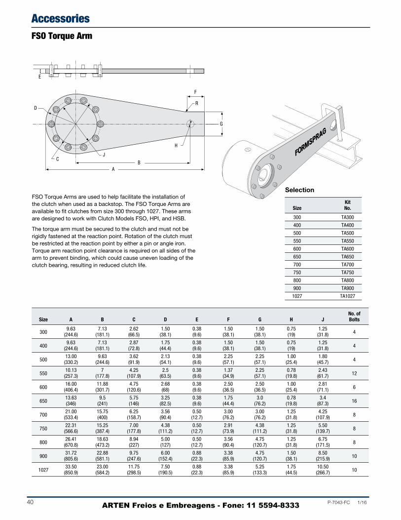
40 P-7043-FC 1/16
FSO Torque Arms are used to help facilitate the installation of the clutch when used as a backstop. The FSO Torque Arms are available to fit clutches from size 300 through 1027. These arms are designed to work with Clutch Models FSO, HPI, and HSB.
The torque arm must be secured to the clutch and must not be rigidly fastened at the reaction point. Rotation of the clutch must be restricted at the reaction point by either a pin or angle iron. Torque arm reaction point clearance is required on all sides of the arm to prevent binding, which could cause uneven loading of the clutch bearing, resulting in reduced clutch life.
E
F
R
H
G
BA
D
CJ
Kit Size No.
300 TA300
400 TA400
500 TA500
550 TA550
600 TA600
650 TA650
700 TA700
750 TA750
800 TA800
900 TA900
1027 TA1027
No. of Size A B C D E F G H J Bolts
300 9.63 7.13 2.62 1.50 0.38 1.50 1.50 0.75 1.25
4 (244.6) (181.1) (66.5) (38.1) (9.6) (38.1) (38.1) (19) (31.8)
400 9.63 7.13 2.87 1.75 0.38 1.50 1.50 0.75 1.25
4 (244.6) (181.1) (72.8) (44.4) (9.6) (38.1) (38.1) (19) (31.8)
500 13.00 9.63 3.62 2.13 0.38 2.25 2.25 1.00 1.80
4 (330.2) (244.6) (91.9) (54.1) (9.6) (57.1) (57.1) (25.4) (45.7)
550 10.13 7 4.25 2.5 0.38 1.37 2.25 0.78 2.43
12 (257.3) (177.8) (107.9) (63.5) (9.6) (34.9) (57.1) (19.8) (61.7)
600 16.00 11.88 4.75 2.68 0.38 2.50 2.50 1.00 2.81
6 (406.4) (301.7) (120.6) (68) (9.6) (36.5) (36.5) (25.4) (71.1)
650 13.63 9.5 5.75 3.25 0.38 1.75 3.0 0.78 3.4
16 (346) (241) (146) (82.5) (9.6) (44.4) (76.2) (19.8) (87.3)
700 21.00 15.75 6.25 3.56 0.50 3.00 3.00 1.25 4.25
8 (533.4) (400) (158.7) (90.4) (12.7) (76.2) (76.2) (31.8) (107.9)
750 22.31 15.25 7.00 4.38 0.50 2.91 4.38 1.25 5.50
8 (566.6) (387.4) (177.8) (111.2) (12.7) (73.9) (111.2) (31.8) (139.7)
800 26.41 18.63 8.94 5.00 0.50 3.56 4.75 1.25 6.75
8 (670.8) (473.2) (227) (127) (12.7) (90.4) (120.7) (31.8) (171.5)
900 31.72 22.88 9.75 6.00 0.88 3.38 4.75 1.50 8.50
10 (805.6) (581.1) (247.6) (152.4) (22.3) (85.9) (120.7) (38.1) (215.9)
1027 33.50 23.00 11.75 7.50 0.88 3.38 5.25 1.75 10.50
10 (850.9) (584.2) (298.5) (190.5) (22.3) (85.9) (133.3) (44.5) (266.7)
Selection
FSO Torque Arm
Accessories
ARTEN Freios e Embreagens - Fone: 11 5594-8333

P-7043-FC 1/16 41
Stieber has two manufacturing facilities: one in Munich and a second in Heidelberg. These plants have produced identical clutches marketed under different part numbers as listed in the chart below. The models listed in bold are in current production and supersede the other model.
Munich Heidelberg Munich Heidelberg Munich Heidelberg
AS NSS CAB RS/BI, RBI
ASNU NFS CA —
AN NF — ETK CLA RIW, RIZ
ANG/ANR NFR — ETKG CLAP RIWN, RINZ
AG GFR F… RS/BF
AL(P) CR —
AGP GFRN CSK KK
AL..G EOC CSK..P —
ALB..M RS/RW CSK..RS —
ALB..M UGF/UGR CLV(P) RAZ, RANZ
AV..04 RS/BW — GFK
AV —
AK —
AA —
AR —
ALZ —
AVZ —
ASK —
AE —
— KI
Stieber Interchange Chart
Cross-Reference Part Numbers
Formsprag Morse Renald Marland
FS-02 — SA-02 —
FS-04 — SA-04 —
FS-05 — SA-05 —
FSR-3 PB-3A SB-3 —
FSR-5 PB-5A SB-5 —
FSR-6 PB-6A SB-6 —
FSR-8 PB-8A SB-8 —
FSR-10 PB-10A SB-10 —
FSR-12 PB-12A SB-12 —
FSR-14 PB-14A SB-14 —
FSR-16 PB-16A SB-16 —
FSO-300 MG-300A — —
FSO-400 MG-400A *SO-400 RMS-14
FSO-500 MG-500A *SO-500 RMS-21
FSO-550 — — RMS-26
FSO-600 MG-600A *SO-600 RMS-32
FSO-650 — — RMS-40
FSO-700 MG-700A *SO-700 RMS-47
FS-750 MG-750A *SO-750 RMS-55
FS-800 MG-800A *SO-800 RMS-72
FS-900 MG-900A *SO-900 —
FS-1027 MG-1000A *SO-1000 —
HPI-300 MI-300A — —
HPI-400 MI-400A SX-400 RMS-14
HPI-500 MI-500A SX-500 RMS-21
— — — RMS-26
HPI-600 MI-600A SX-600 RMS-32
— — — RMS-40
HPI-700 MI-700A SX-700 RMS-47
HPI-750 MI-750A SX-750 RMS-55
HPI-800 MI-800A SX-800 RMS-72
HPI-900 MI-900A SX-900 —
HPI-1027 MI-1000A SX-1000 —
FS-100 HT-10 — —
FS-200 HT-20 — —
FS-300 HT-30 — —
FSO-300L† MO-300A — —
FSO-400L† MO-400A — —
FSO-500L† MO-500A — —
FSO-600L† MO-600A — —
FSO-700L† MO-700A — —
FSO-750L† MO-750A — —
FSO-800L† MO-800A — —
FSO-900L† MO-900A — —
FSO-1027L† MO-1000A — —
* Also available for end face GR lubrication † FSO Series with labyrinth seal option
Cross-Reference Part Numbers
Stieber Interchange Chart
ARTEN Freios e Embreagens - Fone: 11 5594-8333

42 P-7043-FC 1/16
Nominal Bore Shaft Bore Diameter Diameter
.500 .499/.500 .499/.498 .625 .624/.625 .624/.623 .750 .749/.750 .749/.748 .875 .874/.875 .874/.873
1.000 0.999/1.000 .999/.998 1.125 1.124/1.125 1.124/1.123 1.250 1.249/1.250 1.249/1.248 1.312 1.312/1.313 1.311/1.310 1.375 1.374/1.375 1.374/1.373 1.500 1.499/1.500 1.499/1.498 1.625 1.624/1.625 1.624/1.623 1.750 1.749/1.750 1.749/1.748 1.937 1.9365/1.9375 1.9365/1.9355
2.000 1.999/2.000 1.999/1.998 2.125 2.124/2.125 2.124/2.123 2.250 2.2485/2.2500 2.2485/2.2475 2.375 2.375/2.376 2.375/2.374 2.437 2.4360/2.4375 2.4360/2.4350 2.437 2.4365/2.4375 2.4365/2.4355 2.500 2.4985/2.5000 2.4985/2.4975 2.625 2.624/2.625 2.624/2.623 2.750 2.7485/2.7500 2.7485/2.7475 2.937 2.9360/2.9375 2.9360/2.9350
3.000 2.9985/3.0000 2.9985/2.9975 3.250 3.2485/3.2500 3.2485/3.2475 3.437 3.4360/3.4375 3.4360/3.4350 3.500 3.4985/3.5000 3.4985/3.4975 3.750 3.7485/3.7500 3.7485/3.7475 3.937 3.9360/3.9375 3.9360/3.9350 3.937 3.9355/3.9370 3.9355/3.9345
4.000 3.9985/4.0000 3.9985/3.9975 4.000 3.998/4.000 3.998/3.997 4.250 4.248/4.250 4.248/4.247 4.250 4.2485/4.2500 4.2485/4.2470 4.437 4.4355/4.4375 4.4355/4.4345 4.437 4.4360/4.4375 4.4360/4.4350 4.500 4.498/4.500 4.498/4.497 4.750 4.748/4.750 4.748/4.747 4.937 4.9355/4.9375 4.9355/4.9345 4.937 4.9360/4.9375 4.9360/4.9345
5.000 4.998/5.000 4.998/4.997 5.000 5.002/5.004 5.001/5.000 5.250 5.248/5.250 5.248/5.247 5.437 5.4355/5.4375 5.4355/5.4345 5.437 5.435/5.437 5.435/5.434 5.500 5.498/5.500 5.498/5.497 5.750 5.748/5.750 5.748/5.747 5.937 5.9355/5.9375 5.9355/5.9345 5.937 5.9360/5.9375 5.9360/5.9350
6.000 5.998/6.000 5.998/5.997 6.250 6.248/6.250 6.248/6.247 6.437 6.4355/6.4375 6.4355/6.4345 6.437 6.436/6.438 6.436/6.435 6.500 6.498/6.500 6.498/6.497 6.750 6.748/6.750 6.748/6.747 6.937 6.9355/6.9375 6.9355/6.9345
Note: On Models 750 thru 5000, Formsprag may elect to
supply a stepped key in the event of keyseat
distortion during heat treat of inner race.
Nominal Bore Shaft Bore Diameter Diameter
7.000 7.000/6.998 6.997/6.998 7.500 7.504/7.506 7.503/7.502 7.750 7.754/7.756 7.753/7.752
8.000 8.004/8.006 8.003/8.002 8.250 8.254/8.256 8.253/8.252 8.500 8.504/8.506 8.503/8.502 8.750 8.754/8.756 8.753/8.752
9.000 9.004/9.006 9.003/9.002 9.250 9.254/9.256 9.253/9.252 9.500 9.504/9.506 9.503/9.502 9.750 9.754/9.756 9.753/9.752
10.000 10.004/10.006 10.003/10.002 10.500 10.504/10.506 10.503/10.502
11.000 11.004/11.006 11.003/11.002 11.500 11.504/11.506 11.503/11.502
12.000 12.004/12.006 12.003/12.001 12.250 12.254/12.256 12.253/12.251 12.500 12.504/12.506 12.503/12.501
13.000 13.004/13.006 13.003/13.001 13.250 13.254/13.256 13.253/13.251 13.500 13.504/13.506 13.503/13.501 13.750 13.754/13.756 13.753/13.751
14.000 14.004/14.006 14.003/14.001 14.250 14.254/14.256 14.253/14.251 14.500 14.504/14.506 14.503/14.501 14.750 14.754/14.756 14.753/14.751
15.000 15.004/15.006 15.003/15.001 15.250 15.254/15.256 15.253/15.251 15.500 15.504/15.506 15.503/15.501 15.750 15.754/15.756 15.753/15.751
16.000 16.004/16.007 16.003/16.001 16.250 16.254/16.257 16.253/16.251 16.500 16.504/16.507 16.503/16.501 16.750 16.754/16.757 16.753/16.751
17.000 17.004/17.007 17.003/17.001 17.250 17.254/17.257 17.253/17.251 17.500 17.504/17.507 17.503/17.501 17.750 17.754/17.757 17.753/17.751
18.000 18.004/18.007 18.003/18.001 18.250 18.254/18.257 18.253/18.251 18.500 18.504/18.507 18.503/18.501 18.750 18.754/18.757 18.753/18.751
19.000 19.004/19.007 19.003/19.001
20.000 20.004/20.007 20.003/20.0011 Model 750 only2 Model 900 only3 Model 1027 only4 Model 1051 only5 FSO 600/2.00 tolerance 2.000/2.0016 Model 800 only
Bore and shaft tolerances listed below will give the recommended fit for each size clutch. If a press fit is necessary, never exceed .001” (.025mm) interference fit. For all bore and shaft sizes not listed below use same tolerances and fits as next larger size.
5
1
6
2, 6
2
2
2
4
3
3
3
Nominal Bore Shaft Series Bore Diameter Diameter
.250 .250/.252 .250/.249
FS.375 .375/.377 .3745/.374
.500 .500/.502 .4995/.499
.625 .625/.626 .6245/.6240
.375 .375/.376 .3745/.374
.500 .500/.501 .4995/.499
.625 .625/.626 .6245/.624
.687 .687/.688 .6865/.6860
.750 .750/.751 .7495/.749
.875 .875/.876 .8745/.874
1.000 1.000/1.001 .9995/.999
FSR1.125 1.125/1.126 1.1245/1.1235
1.250 1.250/1.251 1.2495/1.2485
1.375 1.375/1.376 1.3745/1.3735
1.500 1.500/1.501 1.4995/1.4985
1.625 1.625/1.626 1.6245/1.6235
1.750 1.750/1.751 1.7495/1.7485
1.875 1.875/1.876 1.8745/1.8735
2.000 2.000/2.001 1.9995/1.9985
2.187 2.187/2.188 2.1865/2.1855
* For LLH series, see page 34.
Sleeve Bearing Clutches
English (inches) Ball Bearing Clutches (except LLH Series)
Bore Sizes and Shaft Tolerances
Engineering Data
ARTEN Freios e Embreagens - Fone: 11 5594-8333

P-7043-FC 1/16 43
Nominal Bore Shaft Series Bore Diameter Diameter
6.35 6.35/6.401 6.35/6.325
FS9.525 9.525/9.576 9.512/9.500 12.70 12.70/12.751 12.687/12.675 15.875 15.875/15.900 15.862/15.850
9.525 9.525/9.550 9.512/9.500 12.70 12.70/12.725 12.687/12.675 15.875 15.875/15.900 15.862/15.850 17.450 17.450/17.475 17.437/17.424 19.05 19.05/19.075 19.037/19.025 22.225 22.225/22.250 22.212/22.200
FSR 25.400 25.400/25.425 25.387/25.375 28.575 28.575/28.600 28.562/28.537 31.75 31.75/31.775 31.737/31.712 34.925 34.925/34.950 34.912/34.887 38.1 38.1/38.125 38.087/38.062
41.275 41.275/41.300 41.262/41.237 44.45 44.45/44.475 44.437/44.412 47.625 47.625/47.650 47.612/47.587 50.8 50.8/50.825 50.787/50.762
55.550 55.550/55.575 55.537/55.512
* For LLH series, see page 35.
Nominal Bore Shaft Bore Diameter Diameter
177.800 177.800/177.749 177.724/177.749 190.500 190.602/190.652 190.576/190.551 196.850 196.952/197.002 196.926/196.901
203.200 203.302/203.352 203.276/203.251 209.550 209.652/209.702 209.626/209.601 215.900 216.002/216.052 215.976/215.951 222.250 222.352/222.402 222.326/222.301
228.600 228.702/228.752 228.676/228.651 234.950 235.052/235.102 235.026/235.001 241.300 241.402/241.452 241.376/241.351 247.650 247.752/247.802 247.726/247.701
254.000 254.102/254.152 254.076/254.051 266.700 266.802/266.852 266.776/266.751
279.400 279.502/279.552 279.476/279.451 292.100 292.202/292.252 292.176/292.151
304.800 304.902/304.952 304.876/304.825 311.150 311.252/311.302 311.226/311.175 317.500 317.602/317.652 317.576/317.525
330.200 330.302/330.352 330.276/330.225 336.550 336.652/336.702 336.626/336.575 342.900 343.002/343.052 342.976/342.925 349.250 349.352/349.402 349.326/349.275
355.600 355.702/355.752 355.676/355.625 361.950 362.052/362.102 362.026/361.975 368.300 393.802/368.452 368.376/368.325 374.650 374.752/374.802 374.726/374.675
381.000 381.102/381.152 381.076/381.025 387.350 387.452/387.502 387.426/387.375 393.700 393.802/393.852 393.776/393.725 400.050 400.152/400.202 400.126/400.075
406.400 406.502/406.578 406.476/406.425 412.750 412.852/412.928 412.826/412.775 419.100 419.202/419.278 419.176/419.125 425.450 425.552/425.628 425.526/425.475
431.800 431.902/431.978 431.876/431.825 438.150 438.252/438.328 438.226/438.175 444.500 444.602/444.678 444.576/444.525 450.850 450.952/451.028 450.926/450.875
457.200 457.302/457.378 457.276/457.225 463.550 463.652/463.728 463.626/463.575 469.900 470.002/470.078 469.976/469.925 476.250 476.352/476.428 476.326/476.275
482.600 482.702/482.778 482.676/482.625
508.000 508.102/508.178 508.076/508.0251 Model 750 only2 Model 900 only3 Model 1027 only4 Model 1051 only5 FSO 600/50.8 tolerance 50.800/50.8256 Model 800 only
Bore and shaft tolerances listed below will give the recommended fit for each size clutch. If a press fit is necessary, never exceed .001” (.025mm) interference fit. For all bore and shaft sizes not listed below use same tolerances and fits as next larger size.
For Metric bores the recommended bore tolerances are H7.
Sleeve Bearing Clutches
Metric (millimeters)
Nominal Bore Shaft Bore Diameter Diameter
12.700 12.675/12.700 12.675/12.649 15.875 15.850/15.875 15.850/15.824 19.050 19.025/19.050 19.025/18.999 22.225 22.200/22.225 22.200/22.174
25.400 25.375/25.400 25.375/25.349 28.575 28.550/28.575 28.550/28.524 31.750 31.725/31.750 31.725/31.699 33.325 33.299/33.325 33.299/33.274 34.925 34.900/34.925 34.900/34.874 38.100 38.075/38.100 38.075/38.049 41.275 41.250/41.275 41.250/41.224 44.450 44.425/44.45 44.425/44.399 49.200 49.187/49.213 49.187/49.162
50.800 50.775/50.800 50.775/50.749 53.975 53.950/53.975 53.950/53.924 57.150 57.112/57.150 57.112/57.087 61.900 61.874/61.913 61.874/61.849 61.900 61.887/61.913 61.887/61.862 63.500 63.462/63.500 63.462/63.437 66.675 66.650/66.675 66.650/66.624 69.850 69.812/69.850 69.812/69.787 74.600 74.574/74.613 74.574/74.549
76.200 76.162/76.200 76.162/76.137 82.550 82.512/82.550 82.512/82.487 87.300 87.274/87.313 87.274/87.249 88.900 88.862/88.900 88.862/88.837 95.250 95.212/95.250 95.212/95.187 100.000 99.974/100.013 99.974/99.949 100.000 99.962/100.000 99.962/99.936
101.600 101.562/101.600 101.562/101.537 101.600 101.549/101.600 101.549/101.524 107.950 107.899/107.950 107.899/107.874 107.950 107.912/107.950 107.912/107.874 112.700 112.662/112.713 112.662/112.636 112.700 112.674/112.713 112.674/112.649 114.300 114.249/114.300 114.249/114.224 120.650 120.599/120.650 120.599/120.574 125.400 125.362/125.413 125.362/125.336 125.400 125.374/125.413 125.374/125.336
127.000 126.949/127.000 126.949/126.924 127.000 127.051/127.102 127.025/127.000 133.350 133.299/133.350 133.299/133.274 138.100 138.062/138.113 138.062/138.036 138.100 138.049/138.100 138.049/138.024 139.700 139.649/139.700 139.649/139.624 146.050 145.999/146.050 145.999/145.974 150.800 150.762/150.813 150.762/150.736 150.800 150.774/150.813 150.774/150.749
152.400 152.349/152.400 152.349/152.324 158.750 158.699/158.750 158.699/158.674 163.500 163.462/163.513 163.462/163.436 163.500 163.474/163.525 163.474/163.449 165.100 165.049/165.100 165.049/165.024 171.450 171.399/171.450 171.399/171.374 176.200 176.162/176.213 176.162/176.136
Note: On Models 750 thru 5000, Formsprag may elect to
supply a stepped key in the event of keyseat
distortion during heat treat of inner race.
5
1
6
2, 6
2
2
2
4
3
3
3
Bore Sizes and Shaft Tolerances
Engineering Data
ARTEN Freios e Embreagens - Fone: 11 5594-8333

44 P-7043-FC 1/16
Press fit assembliesShaft and bore tolerances are spec i fied on the pages for each type where press fitting is ap pro pri ate.
As with standard bearings, suitable tool ing must be used for press fit ting such that no axial load is trans mit ted through the inner part of the clutch during assembly.
Metric Key assembliesFor all overrunning clutch inner races connect ed to shaft by a key, our stan dard bore tol er ance is H7, with key way to JS10.
We recommend a shaft tolerance of h6 or j6. For maximum indexing ac cu ra cy, adjusted keys should be ma chined to give no clearance.
b
h
t 2t 1
D
Mounting ExamplesListed below are a number of clutch models that are used in backstopping applications. In each case the clutch must be axially restrained on the shaft and the torque arm must be restrained from rotating, but free to float in the axial and radial planes to avoid preloading the internal bearings of the clutch.
(Metric keyseat dimensions listed on page 45.)
Mounting Requirements
Engineering Data
HSB
FSOLLH
FHB
ARTEN Freios e Embreagens - Fone: 11 5594-8333
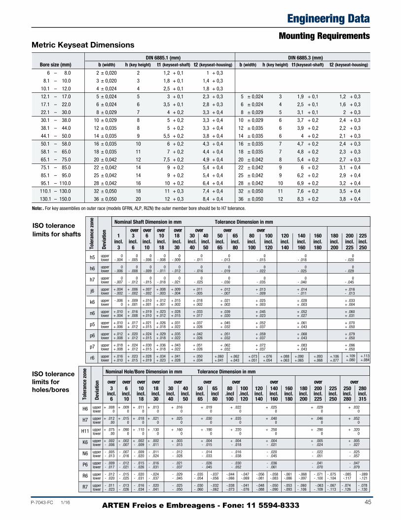
P-7043-FC 1/16 45
1 3 6 10 18 30 40 incl. incl. incl. incl. incl. incl. incl. 3 6 10 18 30 40 50
h5 upper 0 0 0 0 0 0 lower - .004 - .005 - .006 - .008 - .009 - .011
h6 upper 0 0 0 0 0 0 lower - .006 - .008 - .009 - .011 - .012 - .016
h7 upper 0 0 0 0 0 0 lower - .007 - .012 - .015 - .018 - .021 - .025
j6 upper + .004 + .006 + .007 + .008 + .009 + .011 lower - .002 - .002 - .002 - .003 - .004 - .005
k6 upper - .006 + .009 + .010 + .012 + .015 + .018 lower 0 + .001 + .001 + .001 + .002 + .002
n6 upper + .010 + .016 + .019 + .023 + .028 + .033 lower + .004 + .008 + .010 + .012 + .015 + .017
p5 upper + .010 + .017 + .021 + .026 + .031 + .037 lower + .006 + .012 + .015 + .018 + .022 + .026
p6 upper + .012 + .020 + .024 + .029 + .035 + .042 lower + .008 + .012 + .015 + .018 + .022 + .026
p7 upper + .018 + .024 + .030 + .036 + .043 + .051 lower + .008 + .012 + .015 + .018 + .022 + .026
r6 upper + .016 + .023 + .028 + .034 + .041 + .050lower + .010 + .015 + .019 + .023 + .028 + .034
DIN 6885.1 (mm) DIN 6885.3 (mm)Bore size (mm) b (width) h (key height) t1 (keyseat-shaft) t2 (keyseat-housing) b (width) h (key height) t1(keyseat-shaft) t2 (keyseat-housing)
6 – 8.0 2 ± 0,020 2 1,2 + 0,1 1 + 0,3
8.1 – 10.0 3 ± 0,020 3 1,8 + 0,1 1,4 + 0,3
10.1 – 12.0 4 ± 0,024 4 2,5 + 0,1 1,8 + 0,3
12.1 – 17.0 5 ± 0,024 5 3 + 0,1 2,3 + 0,3 5 ± 0,024 3 1,9 + 0,1 1,2 + 0,3
17.1 – 22.0 6 ± 0,024 6 3,5 + 0,1 2,8 + 0,3 6 ± 0,024 4 2,5 + 0,1 1,6 + 0,3
22.1 – 30.0 8 ± 0,029 7 4 + 0,2 3,3 + 0,4 8 ± 0,029 5 3,1 + 0,1 2 + 0,3
30.1 – 38.0 10 ± 0,029 8 5 + 0,2 3,3 + 0,4 10 ± 0,029 6 3,7 + 0,2 2,4 + 0,3
38.1 – 44.0 12 ± 0,035 8 5 + 0,2 3,3 + 0,4 12 ± 0,035 6 3,9 + 0,2 2,2 + 0,3
44.1 – 50.0 14 ± 0,035 9 5,5 + 0,2 3,8 + 0,4 14 ± 0,035 6 4 + 0,2 2,1 + 0,3
50.1 – 58.0 16 ± 0,035 10 6 + 0,2 4,3 + 0,4 16 ± 0,035 7 4,7 + 0,2 2,4 + 0,3
58.1 – 65.0 18 ± 0,035 11 7 + 0,2 4,4 + 0,4 18 ± 0,035 7 4,8 + 0,2 2,3 + 0,3
65.1 – 75.0 20 ± 0,042 12 7,5 + 0,2 4,9 + 0,4 20 ± 0,042 8 5,4 + 0,2 2,7 + 0,3
75.1 – 85.0 22 ± 0,042 14 9 + 0,2 5,4 + 0,4 22 ± 0,042 9 6 + 0,2 3,1 + 0,4
85.1 – 95.0 25 ± 0,042 14 9 + 0,2 5,4 + 0,4 25 ± 0,042 9 6,2 + 0,2 2,9 + 0,4
95.1 – 110.0 28 ± 0,042 16 10 + 0,2 6,4 + 0,4 28 ± 0,042 10 6,9 + 0,2 3,2 + 0,4
110.1 – 130.0 32 ± 0,050 18 11 + 0,3 7,4 + 0,4 32 ± 0,050 11 7,6 + 0,2 3,5 + 0,4
130.1 – 150.0 36 ± 0,050 20 12 + 0,3 8,4 + 0,4 36 ± 0,050 12 8,3 + 0,2 3,8 + 0,4
Note: . For key assemblies on outer race (models GFRN, ALP, RIZN) the outer member bore should be to H7 tolerance.
ISO tolerance limits for holes/bores
Nominal Hole/Bore Dimension in mm Tolerance Dimension in mm
Tole
ranc
e zo
ne
Devi
atio
n
ISO tolerancelimits for shafts
over over over over over over over
Nominal Shaft Dimension in mm Tolerance Dimension in mm
Tole
ranc
e zo
ne
Devi
atio
n
Metric Keyseat Dimensions
+.109 +.113 +.080 +.084
over over over over over over over over over over 3 6 10 18 30 40 50 65 80 100 120 140 160 180 200 225 250 280 incl. incl. incl. incl. incl. incl. incl. incl .incl .incl. incl. incl. incl. incl. incl. incl. incl. incl. 6 10 18 30 40 50 65 80 100 120 140 160 180 200 225 250 280 315
H6 upper + .008 + .009 + .011 + .013 + .016 + .019 + .022 + .025 + .029 + .032 lower 0 0 0 0 0 0 0 0 0 0
H7 upper + .012 + .015 + .018 + .021 + .025 + .030 + .035 + .040 + .046 + .052 lower .00 0 0 0 0 0 0 0 0 0
H11 upper + .075 + .090 + .110 + .130 + .160 + .190 + .220 + .250 + .290 + .320 lower .00 0 0 0 0 0 0 0 0 0
K6 upper + .002 + .002 + .002 + .002 + .003 + .004 + .004 + .004 + .005 + .005 lower - .006 - .007 - .009 - .011 - .013 - .015 - .018 - .021 - .024 - .027
N6 upper - .005 - .007 - .009 - .011 - .012 - .014 - .016 - .020 - .022 - .025 lower - .013 - .016 - .020 - .024 - .028 - .033 - .038 - .045 - .051 - .057
P6 upper - .009 - .012 - .015 - .016 - .021 - .026 - .030 - .036 - .041 - .047 lower - .017 - .021 - .026 - .031 - .037 - .045 - .052 - .061 - .070 - .079
R6 upper - .012 - .015 - .020 -.024 - .029 - .035 -.037 -.044 -.047 -.056 -.058 -.061 -.068 - .071 - .075 -.085 -.089 lower - .020 - .025 - .031 - .037 - .045 - .054 -.056 -.066 -.069 -.081 -.083 -.086 -.097 - .100 - .104 -.117 -.121
R7 upper - .011 - .013 - .016 - .020 - .025 - .030 -.032 -.038 -.041 -.048 -.050 -.053 - .060 -.063 - .067 - .074 - .078 lower - .023 - .026 - .034 - .041 - .050 - .060 -.062 -.073 -.076 -.088 -.090 -.093 - .106 - .109 - .113 - .126 - .130
50 65 80 100 120 140 160 180 200 225 incl. incl. incl. incl. incl. incl. incl. incl. incl. incl. 65 80 100 120 140 160 180 200 225 250
0 0 0 0 - .013 - .015 - .018 - .020
0 0 0 0 - .019 - .022 - .025 - .029
0 0 0 0 - .030 - .035 - .040 - .045
+ .012 + .013 + .014 + .016 - .007 - .009 - .011 - .013
+ .021 + .025 + .028 + .033 + .002 + .003 + .003 + .004
+ .039 + .045 + .052 + .060 + .020 + .023 + .027 + .031
+ .045 + .052 + .061 + .070 + .032 + .037 + .043 + .050
+ .051 + .059 + .068 + .079 + .032 + .037 + .043 + .050
+ .062 + .072 + .083 + .096 + .032 + .037 + .043 + .050
+ .060 + .062 + .073 + .076 +.088 + .090 + .093 + .106+ .041 + .043 + .051 + .054 +.063 + .065 + .068 + .077
Mounting Requirements
Engineering Data
ARTEN Freios e Embreagens - Fone: 11 5594-8333
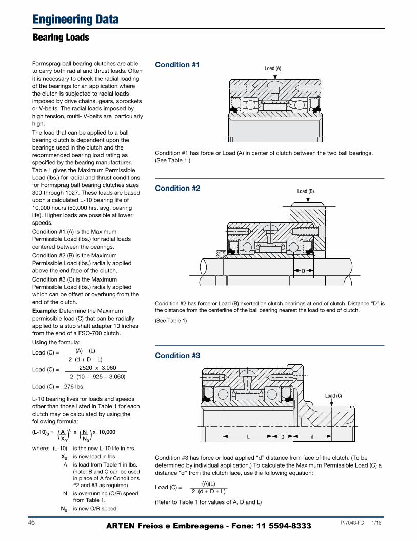
46 P-7043-FC 1/16
L10 bearing lives for loads and speedsother than those listed in Table 1 for eachclutch may be calculated by using thefollowing formula:
(L-10)0 = A 3 x N x 10,000X0 N0
(–– ) (–– )
Engineering DataBearing Loads
Formsprag ball bearing clutches are able to carry both radial and thrust loads. Often it is nec es sary to check the radial loading of the bearings for an application where the clutch is subjected to radial loads imposed by drive chains, gears, sprockets or Vbelts. The radial loads imposed by high tension, multi Vbelts are particularly high.
The load that can be applied to a ball bearing clutch is dependent upon the bearings used in the clutch and the recommended bearing load rating as specified by the bearing manufacturer. Table 1 gives the Maximum Permissible Load (lbs.) for radial and thrust con di tions for Formsprag ball bearing clutches sizes 300 through 1027. These loads are based upon a calculated L10 bearing life of 10,000 hours (50,000 hrs. avg. bearing life). Higher loads are possible at lower speeds.
Condition #1 (A) is the Maximum Permis sible Load (lbs.) for radial loads centered between the bearings.
Condition #2 (B) is the Maximum Permis sible Load (lbs.) radially applied above the end face of the clutch.
Condition #3 (C) is the Maximum Permis sible Load (lbs.) radially applied which can be offset or overhung from the end of the clutch.
Example: Determine the Maximum permissible load (C) that can be radially applied to a stub shaft adapter 10 inches from the end of a FSO700 clutch.
Using the formula:
Load (C) = (A) (L)
2 (d + D + L)
Load (C) = 2520 x 3.060
2 (10 + .925 + 3.060)
Load (C) = 276 lbs.
Condition #1
Condition #1 has force or Load (A) in center of clutch between the two ball bear ings. (See Table 1.)
Condition #2
Condition #3 has force or load applied “d” distance from face of the clutch. (To be determined by individual application.) To calculate the Maximum Permissible Load (C) a distance “d” from the clutch face, use the following equation:
Load (C) =(A)(L)
2 (d + D + L)
(Refer to Table 1 for values of A, D and L)
Condition #3
Condition #2 has force or Load (B) exerted on clutch bearings at end of clutch. Distance “D” is the distance from the centerline of the ball bearing nearest the load to end of clutch.
(See Table 1)
Load (A)
Load (B)
D
Load (C)
L D d
where: (L10) is the new L10 life in hrs.
X0 is new load in lbs.
A is load from Table 1 in lbs. (note: B and C can be used in place of A for Conditions #2 and #3 as required)
N is overrunning (O/R) speed from Table 1.
N0 is new O/R speed.
ARTEN Freios e Embreagens - Fone: 11 5594-8333

P-7043-FC 1/16 47
Engineering DataBearing Loads
Table 1
Maximum Permissible Load Thrust Max Cond. Cond. Cap. @ O/R
Clutch #1 (A) #2 (B) D L Max. O/R Speed No. lb. lb. in. in. Speed lb.* RPM
FSO-300 413 150 .516 1.381 413 3,600
FSO-400 480 160 .675 1.376 467 3,600
FSO-500 816 297 .745 1.990 820 3,000
FSO-600 879 304 .836 1.950 1,039 2,400
FSO-700 2,559 982 .925 3.060 2,810 2,000
FSO-750 1,656 612 1.247 3.550 2,158 1,800
FSO-800 2,412 891 1.251 3.542 3,237 1,500
FSO-900 3,183 1,191 1.257 3.740 4,046 1,350
FSO-1027 1,013 353 1.446 3.355 2,750 1,100
The clutch thrust capacity at Max. O/R speed given in Table 1 is the Maximum permissible load applied in an axial direction to the end of the clutch. The clutch thrust capacity listed in Table 1 is without any radial load applied to the clutch. For applications that have both thrust and radial loads consult Formsprag engineering.
Example: Determine the maximum permissible load that can be radially applied between the bearings of a FSO750 with an over run ning speed of 600 RPM that will result in a L10 bearing life of 10,000 hours.
Since the load is applied between the bearings the value (A) for Condition #1 is used for this calculation. Also, be cause the bearing life is 10,000 hours, the new L10 remains at 10,000 hrs.
Using the bearing life formula:
(L10)0 = A 3 x N x 10,000 X0 N0
Substituting values into the equation:
10,000 = 2,040 3 x 1,800 x 10,000 X0 600
X03 = 2,0403 x 1,800 x 10,000
600 10,000
X0 = 3 2,0403 x 3 x 1
X0 = 2,942 lbs
Answer: The new maximum permissible radial load that can be applied is 2,942 lbs.
℘
(––) ( –– )
(–—–) (–—–)–—– –——
* Always contact Formsprag Engineering for approval when applying axial loads to the clutch.
ARTEN Freios e Embreagens - Fone: 11 5594-8333

48 P-7043-FC 1/16
Proper lubrication and lubricant maintenance are the most important single maintenance factors for long, effective, troublefree clutch operation.
Many models are shipped from the factory prelubricated and ready to install. Some models require lubrication to be added prior to being put into service, and other designs rely on lubrication integral to the application, see the model data pages for details.
Formsprag has evaluated and approved a wide selection of oil and grease lubricants necessary to meet a wide range of customer application needs. If no lubricant is specified on the order, the clutch will be supplied with the standard lubricant
that is listed on the model data page. Not all lubricants are compatible, so before switching check with Formsprag Engineering. Grease lubrication is recommended for applications where: (1) conditions do not permit the type of maintenance required for oil lubricated clutches, (2) the clutch is exposed to severe dusty conditions, (3) the clutch is mounted on a vertical shaft.
The selection of the proper lubricant for each application should include the ambient temperature range; see the table below for a listing of approved lubricants. Contact Formsprag Engineering if you have any questions about lubrication.
Overrunning and Backstopping Applications
+20°F to +150°F(–7°C to +65°C)
Maximum permissible ambient temperature
–20°F to +20°F(–23°C to –7°C)
Ambient temperature
–40°F to +150°F(–40°C to +65°C)
Maximum permissible ambient temperature
+20°F to +150°F(7°C to +65°C)
If below +20°F (–7°C) Consult Formsprag
Chevron GST Oil 68 Mobil DTE Heavy Medium Automatic Transmission Fluid (ATF)** Texaco Regal Oil R&O 68 Shell Turbo Oil 68 Amoco Industrial Oil 68 Exxon Teresstic Oil 68 Sunoco Sunvis 931 Mobil SHC626
Mobil Gargoyle Arctic C Heavy Texaco Regal Oil R&O 46 Automatic Transmission Fluid (ATF)** Amoco Oil Industrial 46 Sunoco Sunvis 921 Mobil SHC624 Royal Purple Synfilm GT (equivalent to ISO #32)
Mobil Jet Oil 2 Shell Aeroshell Turbine Oil 555 (MILPRF23699) Shell Aeroshell Turbine Oil 500 (MILPRF23699) Exxon Turbo Oil 2380 Exxon Turbo Oil 2389 Military Oils MILPRF7808 or MILPRF23699 * Mobil HFA (MILPRF5606)
Fiske Bros. Lubriplate Low Temp Fiske Bros. Aero Lubriplate Shell Aeroshell No. 7 Shell Aeroshell No. 22 Beacon 325
At 150 strokes per minutes or less
At 150 strokes per minutes or less
–10°F or below(–23°C)
Indexing Applications
Oil Lubricants
Mobil DTE Light Oil Automatic Transmission Fluid (ATF)** Texaco Regal Oil R&O 32 Shell Turbo Oil 32 Amoco Industrial Oil 32 Exxon Teresstic Oil 32
Sunoco Sunvis 916 Exxon Zerice 46 Automatic Transmission Fluid (ATF)** Consult Formsprag
Not Applicable Consult Formsprag
* This lubricant is suitable for a low temperature and low speed application.** Any automatic transmission fluid (ATF) without friction reducing agents or high friction modifier, synthetic preferred.
CAUTION: Do not use EP additives type lubricants (extreme pressure characteristics) or those containing slippery additives, such as molybdem disulfide graphite compounds.
Recommended Lubricants
Grease Lubricants
Temperature Range
Oil Lubricants
Lubrication
Engineering Data
ARTEN Freios e Embreagens - Fone: 11 5594-8333

P-7043-FC 1/16 49
Date
Company name
Address
City State Zip
Name of contact Title
Phone Fax
Type of equipment
Type of application
Overrunning Indexing Backstop Clutch Coupling
Maximum torque at clutch
pound-feet, or
HP at RPM
Power Source
Electric motor Diesel engine Turbine Air cylinder
Gasoline engine
Load Application
Smooth Moderate Shock
Lubrication
Runs in oil Not accessible Accessible for lubricating
Type or specification of lubricant
For overrunning or backstop applications
Inner race speed during overrunning RPM max.
Outer race speed during overrunning RPM max.
If both members are rotating during overrunning, are they rotating in the
Same direction Opposite directions
Time cycle of Formsprag clutch
Drive____________minutes Rest____________minutes
Over-run___________minutes
For indexing applications
Indexes per minute__________max.
Degrees per index__________max.
Clutch operating time
hours per day
Shaft diameter (give limits)
Size of keyseat in shaft
Environment
Temperature range °F to °F
Exposed location?
Radiation?
For non-symmetrical clutches and clutch-couplings
a. Identify the end from which the clutch is viewed
b. The (inner, outer) member (drives, over-runs) in the(clockwise, counter-clockwise) direction
Anticipated quantity required
a. For this application
b. Annually
Supply a sketch of your installation.
Note: A clutch is not a coupling. When necessary to couple two shafts, a coupling must be used with the clutch. Ambient temperature should not exceed approxi mately 150°F. It is requested that prints of installation be supplied if available.
Completed by
For Application Assistance call 1-800-927-3262 or Fax (586) 758-5204
Overrunning Clutches Application Data Form
ARTEN Freios e Embreagens - Fone: 11 5594-8333

50 P-7043-FC 1/16
Length
1 in. = 25.4 mm = 0.0254 m1 ft. = 304.8 mm = 0.3048 m
1µm = .00004 in.1 m = 39.37 in.1 m = 3.28 ft.
Area1 in.2 = 6.4516x10⁴ m2
1 ft.2 = 9.29x10² m2
1 m2 = 1550 in.2
1 m2 = 10.764 ft.2
Volume1 in.3 = 1.639x10⁵ m3
1 ft.3 = 2.832x10² m3
1 gal (US) = 3.7854 l
1 m3 = 61023 in.3
1 m3 = 35.315 ft.3
1 l = 0.2642 gal (US)
Mass1 lb. s2 ft.1 = 14.6 kg 1 kg = 6.85x10² lb. s2 ft.1
Force1 lb. = 445 g 1 kg = 2.2 lb.
Pressure1 lb.in.2 = 6.895x10³ Nmm2
(pai) = 6.895x10³ Nm2
1 Nmm2 = 145 lb.in.2
1 bar = 14.2 lb.in.2
Torque1 lb.in. = 0.113 Nm1 lb.ft. = 1.36 Nm
1 Nm = 8.85 lb.in.1 Nm = 0.738 lb.ft.
Work1 Btu = 778 lb.ft.1 Btu = 1055 J = 1.055 kJ1 Btu = 2.93x10⁴ kWh
1 kJ = 0.948 Btu1 kWh = 3410 Btu
Power1 HP = 746 W = 0.746 kW 1 HP = 1.014 CV
1 kW = 1.34 HP1 CV = 0.986 HP
Moment of Inertia1 lb.ft.2 = 0.04214 kgm2
1 lb.in.2 = 2.93x10⁴ kgm2
1 lb.ft. s2 = 1.3847 kgm2
1 lb.in. s2 = 0.1129 kgm2
1 kgm2 = 23.73 lb.ft.2
1 kgm2 = 3417.17 lb.in.2
1 kgm2 = 0.738 lb.ft. s2
1 kgm2 = 8.8507 lb. in. s2
Mass/Volume1 lb.ft.3 = 16.018 kgm3 1 kgm3 = 6.24x10² lb.ft.3
Temperature°F = (1.8x°C) + 32°F = 1.8x(K–273) + 32 K = 5/9x (°F–32) + 273
°C = 5/9x(°F–32)
Performance AssuranceRated torque and speeds of Formsprag Clutch products are provided in current catalogs to assist the buyer in selecting the proper Formsprag Clutch product. In addition, application assistance is offered by Formsprag Clutch for guidance to the buyer in selection of a catalog product and application of custom designed products. Since the actual performance characteristics of all Formsprag Clutch products in the buyer’s application is the responsibility of the buyer, performance assurance is usually accomplished through manufacture of a prototype by Formsprag Clutch, and a test or qualification program on the part of the buyer.
Rotating EquipmentRotating equipment is potentially dangerous and should be properly guarded. The user should check for all applicable safety codes (in local area) and provide a suitable guard. Formsprag clutches and backstops have surfaces which wear with use over time and as a result will need to be replaced. The decision for time of replacement must be made by the operator of the equipment based upon the specific application and performance of the clutch or backstop.
Catalog ChangesThe contents of this catalog are subject to change without notice or obligation.
WarrantyFormsprag LLC warrants that it will repair or replace (whichever in its sole discretion it deems advisable) any product it manufactured and sold which proves to be defective in material or workmanship within a period of one (1) year from date of original purchase for consumer, commercial or industrial use. This warranty extends only to the original purchaser and is not transferable or assignable without Formsprag LLC’s prior consent.
This warranty covers normal use and does not cover damage or defect which results from alterations, accident, neglect, disassembly, or improper installation, operation, or maintenance.
Formsprag LLC’s obligation under this warranty is limited to the repair or replacement of the defective product. In no event shall Formsprag LLC be liable for consequential, indirect or incidental damages of any kind incurred by reason of manufacture, sale or use of any defective product. Formsprag LLC neither assumes nor authorizes any other person to give any other warranty or to assume any other obligation or liability on its behalf.
Conversion Factors
Conversion Factors
ARTEN Freios e Embreagens - Fone: 11 5594-8333
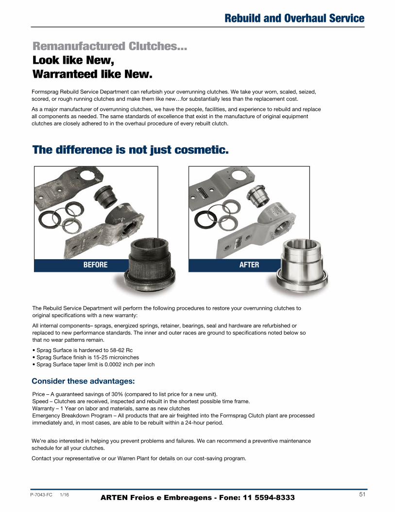
P-7043-FC 1/16 51
Remanufactured Clutches...Look like New,Warranteed like New.
The difference is not just cosmetic.
The Rebuild Service Department will perform the following procedures to restore your overrunning clutches to original specifications with a new warranty:
All internal components– sprags, energized springs, retainer, bearings, seal and hardware are refurbished or replaced to new performance standards. The inner and outer races are ground to specifications noted below so that no wear patterns remain.
• Sprag Surface is hardened to 5862 Rc• Sprag Surface finish is 1525 microinches• Sprag Surface taper limit is 0.0002 inch per inch
Price – A guaranteed savings of 30% (compared to list price for a new unit). Speed – Clutches are received, inspected and rebuilt in the shortest possible time frame.Warranty – 1 Year on labor and materials, same as new clutchesEmergency Breakdown Program – All products that are air freighted into the Formsprag Clutch plant are processed immediately and, in most cases, are able to be rebuilt within a 24hour period.
Consider these advantages:
Formsprag Rebuild Service Department can refurbish your overrunning clutches. We take your worn, scaled, seized, scored, or rough running clutches and make them like new…for substantially less than the replacement cost.
As a major manufacturer of overrunning clutches, we have the people, facilities, and experience to rebuild and replace all components as needed. The same standards of excellence that exist in the manufacture of original equipment clutches are closely adhered to in the overhaul procedure of every rebuilt clutch.
We’re also interested in helping you prevent problems and failures. We can recommend a preventive maintenance schedule for all your clutches.
Contact your representative or our Warren Plant for details on our costsaving program.
BEFORE AFTER
Rebuild and Overhaul Service
ARTEN Freios e Embreagens - Fone: 11 5594-8333

A l t r a I n d u s t r i a l M o t i o n
Check Outwww.AltraMining.comThe website offers the worldwide mining and aggregate marketplace convenient, 24-hour access to the Altra brands, products and applications critical to virtually every operation in the mining process.
The website is organized by 15 mining application categories ranging from shovels and draglines to conveyors, crushers, winders and hoists, and more.
Within these categories are the features and benefits of each Altra product solution that can be applied to improve efficiency, productivity and safety in the mining operation. Each product contains a web link to one of the 13 Altra brands that support the mining industry where engineers can access detailed product specifications.
The website also contains a Mining Solutions Video, Case Studies, a Literature Portal and information on Altra’s Replacement Program for clutches and brakes from Industrial Clutch, Wichita Clutch and Twiflex as well as its Rebuild Program for backstops from Formsprag Clutch and Marland Clutch.
ARTEN Freios e Embreagens - Fone: 11 5594-8333