Embed Size (px)
Citation preview

Sup
erse
ded
by T
HR
CI 1
2030
ST
v2.0
Overbridges and Footbridges
T HR CI 12030 ST
Standard
Version 1.0
Issued date: 13 April 2015
Important Warning
This document is one of a set of standards developed solely and specifically for use on public transport assets which are vested in or owned, managed, controlled, commissioned or funded by the NSW Government, a NSW Government agency or a Transport Agency (as defined in the Asset Standards Authority Charter). It is not suitable for any other purpose.
You must not use or adapt it or rely upon it in any way unless you are authorised in writing to do so by a relevant NSW Government agency. If this document forms part of a contract with, or is a condition of approval by a NSW Government agency, use of the document is subject to the terms of the contract or approval.
This document may not be current. Current standards are available for download from the Asset Standards Authority website at www.asa.transport.nsw.gov.au.
© State of NSW through Transport for NSW

T HR CI 12030 ST Overbridges and Footbridges
Version 1.0 Issued date: 14 April 2015
Sup
erse
ded
by T
HR
CI 1
2030
ST
v2.0 Standard governance
Owner: Lead Civil Engineer, Asset Standards Authority
Authoriser: Chief Engineer Rail, Asset Standards Authority
Approver Director, Asset Standards Authority on behalf of the ASA Configuration Control Board
Document history
Version Summary of Changes
1.0 First issue
For queries regarding this document, please email the ASA at [email protected] or visit www.asa.transport.nsw.gov.au
© State of NSW through Transport for NSW

T HR CI 12030 ST Overbridges and Footbridges
Version 1.0 Issued date: 14 April 2015
Preface The Asset Standards Authority (ASA) is an independent unit within Transport for NSW (TfNSW)
and is the network design and standards authority for defined NSW transport assets.
The ASA is responsible for developing engineering governance frameworks to support industry
delivery in the assurance of design, safety, integrity, construction, and commissioning of
transport assets for the whole asset life cycle. In order to achieve this, the ASA effectively
discharges obligations as the authority for various technical, process, and planning matters
across the asset life cycle.
The ASA collaborates with industry using stakeholder engagement activities to assist in
achieving its mission. These activities help align the ASA to broader government expectations
of making it clearer, simpler, and more attractive to do business within the NSW transport
industry, allowing the supply chain to deliver safe, efficient, and competent transport services.
The ASA develops, maintains, controls, and publishes a suite of standards and other
documentation for transport assets of TfNSW. Further, the ASA ensures that these standards
are performance-based to create opportunities for innovation and improve access to a broader
competitive supply chain.
This standard was developed by the Chief Engineer Rail section of the ASA, reviewed by a
committee of TfNSW cluster representatives and approved by the ASA Configuration Control
Board.
This standard details the design requirements for overbridges and footbridges on the TfNSW
heavy rail network and was developed from RailCorp standard ESC 320 Overbridges and
Footbridges, Version 2.2.
ESC 320 is withdrawn with the publication of this standard.
This standard is a first issue.
© State of NSW through Transport for NSW Page 3 of 36
Sup
erse
ded
by T
HR
CI 1
2030
ST
v2.0

T HR CI 12030 ST Overbridges and Footbridges
Version 1.0 Issued date: 14 April 2015
Foreword
This standard is intended to be used by competent personnel engaged in the provision of
services relating to rail infrastructure. Compliance with the requirements in this standard will not,
by itself, be sufficient to ensure that satisfactory outcomes will be produced. Personnel
providing services based on the standard need to bring appropriate expertise to the matters
under consideration.
In addition to the requirements of this standard, asset decisions shall take into account the life
cycle cost considerations specified in T MU AM 01001 ST Life Cycle Costing.
If, when using the standard, it is considered that the intent of stated requirements is not clear, a
clarification should be sought from the ASA.
© State of NSW through Transport for NSW Page 4 of 36
Sup
erse
ded
by T
HR
CI 1
2030
ST
v2.0
T HR CI 12030 ST Overbridges and Footbridges
Version 1.0 Issued date: 14 April 2015
Table of contents 1. Introduction .............................................................................................................................................. 7
2. Purpose .................................................................................................................................................... 72.1. Scope ..................................................................................................................................................... 72.2. Application ............................................................................................................................................. 7
3. Reference documents ............................................................................................................................. 8
4. Terms and definitions ........................................................................................................................... 10
5. Safety requirements .............................................................................................................................. 10
6. Environmental and heritage requirements ......................................................................................... 11
7. Construction .......................................................................................................................................... 12
8. Maintenance ........................................................................................................................................... 12
9. Decommissioning or disposal ............................................................................................................. 12
10. Nameplates and plaques ...................................................................................................................... 13
11. Attached advertising signs ................................................................................................................... 13
12. Design criteria ........................................................................................................................................ 1412.1. Configuration ................................................................................................................................... 1412.2. Aesthetics ........................................................................................................................................ 1512.3. Graffiti .............................................................................................................................................. 1512.4. Design standards ............................................................................................................................. 1512.5. Roads and Maritime Services Bridge Technical Directions ............................................................. 1612.6. Design life ........................................................................................................................................ 1612.7. Traffic loads ..................................................................................................................................... 1612.8. Collision loads and protection requirements .................................................................................... 1612.9. Earthquake effects ........................................................................................................................... 1812.10. Fire effects for footbridges ............................................................................................................... 1812.11. Bearings and deck joints .................................................................................................................. 1912.12. Clearances ....................................................................................................................................... 1912.13. Abutments and wingwalls ................................................................................................................ 1912.14. Earthworks ....................................................................................................................................... 1912.15. Drainage .......................................................................................................................................... 1912.16. Stepways ......................................................................................................................................... 2012.17. Attachment of overhead wiring ........................................................................................................ 2012.18. Cathodic protection .......................................................................................................................... 2012.19. Bird nesting ...................................................................................................................................... 2012.20. Approved materials .......................................................................................................................... 2012.21. Formwork ......................................................................................................................................... 2112.22. Provision for services ....................................................................................................................... 2112.23. Traffic barriers .................................................................................................................................. 2112.24. Safety screens ................................................................................................................................. 2212.25. Protection screens ........................................................................................................................... 22 © State of NSW through Transport for NSW Page 5 of 36
Sup
erse
ded
by T
HR
CI 1
2030
ST
v2.0

T HR CI 12030 ST Overbridges and Footbridges
Version 1.0 Issued date: 14 April 2015
12.26. Earthing and bonding ....................................................................................................................... 2312.27. Clearances to electrical services and equipment ............................................................................ 2312.28. Drawing standards ........................................................................................................................... 24
13. Refurbishment of overbridges and footbridges ................................................................................. 2413.1. Design criteria for refurbishment...................................................................................................... 2413.2. Traffic barrier replacement ............................................................................................................... 2513.3. Collision protection .......................................................................................................................... 26
14. Load rating ............................................................................................................................................. 26
15. Collision protection of existing bridges .............................................................................................. 26
16. Provision of safe areas ......................................................................................................................... 2716.1. Safety refuge details ........................................................................................................................ 2816.2. Handhold device details ................................................................................................................... 2816.3. No safe place sign ........................................................................................................................... 28
17. Street name signs .................................................................................................................................. 2917.1. Location ........................................................................................................................................... 2917.2. Fixing details .................................................................................................................................... 3017.3. Front details ..................................................................................................................................... 3017.4. Manufacturing details ....................................................................................................................... 30
Appendix A RMS Bridge Technical Directions .................................................................................... 31
Appendix B Guidance regarding compliance of refurbishment works ............................................. 32
Appendix C Guard rails .......................................................................................................................... 33C.1. Configuration details ............................................................................................................................ 33C.2. Signalling interface .............................................................................................................................. 34C.3. Joints in guard rails .............................................................................................................................. 35C.4. Automatic Train Protection interface ................................................................................................... 35
Appendix D Aesthetic considerations and guidelines ........................................................................ 36
© State of NSW through Transport for NSW Page 6 of 36
Sup
erse
ded
by T
HR
CI 1
2030
ST
v2.0

T HR CI 12030 ST Overbridges and Footbridges
Version 1.0 Issued date: 14 April 2015
1. Introduction An overbridge is a bridge carrying vehicular traffic over the track. Overbridges may include
provisions for pedestrians and cyclists.
A footbridge is a bridge over the track that carries pedestrian traffic only. Footbridges may be
standalone structures at stations; standalone structures between stations; or, when combined
with an overhead booking office or retail outlets, can be part of station concourses.
2. Purpose This standard details the design, refurbishment, decommissioning and disposal requirements
for overbridges and footbridges on the Transport for New South Wales (TfNSW) heavy rail
network.
This document also provides guidance on compliance of refurbished works and aesthetic
considerations for overbridges and footbridges.
2.1. Scope This standard does not cover the load rating of overbridges and footbridges. This work shall be
undertaken in accordance with AS 5100.7 Bridge design – Part 7: Rating of existing bridges.
2.2. Application This standard applies to the design of new overbridges and footbridges and the design of
refurbishment works for existing overbridges and footbridges on the TfNSW heavy rail network.
This standard is intended to be used by competent personnel engaged in the provision of
services relating to rail infrastructure. Compliance with the requirements in this standard will not,
by itself, be sufficient to ensure that satisfactory outcomes will be produced. Personnel
providing services based on the standard need to bring appropriate expertise to the matters
under consideration.
If, when using the standard, it is found that the intent of stated requirements is not clear, a
clarification should be sought from the Asset Standards Authority (ASA).
© State of NSW through Transport for NSW Page 7 of 36
Sup
erse
ded
by T
HR
CI 1
2030
ST
v2.0

T HR CI 12030 ST Overbridges and Footbridges
Version 1.0 Issued date: 14 April 2015
3. Reference documents The following documents are cited in the text. For dated references, only the cited edition
applies. For undated references, the latest edition of the referenced document applies.
Australian standards
AS 1085.1 Railway track material – Part 1: Steel rails
AS 1744 Forms of letters and numerals for road signs (known as Standard alphabets for road
signs)
AS 1530.4 Methods for fire tests on building materials, components and structures – Part 4:
Fire-resistance tests for elements of construction
AS 1906.1 Retroreflective materials and devices for road traffic control purposes –
Retroreflective materials
AS 2832.5 Cathodic protection of metals – Part 5: Steel in concrete structures
AS 5100 Bridge design
AS 5100.1 Bridge design – Part 1: Scope and general principles
AS 5100.2 Bridge design – Part 2: Design loads
AS 5100.7 Bridge design – Part 7: Rating of existing bridges
AS/NZS 1734 Aluminium and aluminium alloys – Flat sheet, coiled sheet and plate
AS/NZS 3845 Road safety barrier systems
Transport for NSW standards
EP 10 01 00 06 SP HV Aerial Line Standards for Design and Construction
ESB 000 Introduction
ESB 001 Station Context and Processes
ESB 002 Design Principles
ESB 003 Station Functional Spaces
ESB 004 Station Services and Systems
ESC 100 Civil Technical Maintenance Plan
ESC 302 Structures Defect Limits
ESC 215 Transit Space
ESC 220 Rail and Rail Joints
ESC 350 Platforms and Retaining Walls
ESC 420 Track Drainage © State of NSW through Transport for NSW Page 8 of 36
Sup
erse
ded
by T
HR
CI 1
2030
ST
v2.0
T HR CI 12030 ST Overbridges and Footbridges
Version 1.0 Issued date: 14 April 2015
ESG 100.17 Signal Design Principles Track Circuits
SPC 301 Structures Construction
T HR EL 08001 ST Safety Screens and Barriers for 1500 V OHW Equipment
T HR EL 20003 ST Underground installation configurations for high voltage and 1500 V dc
cables
T MU AM 01001 ST Life Cycle Costing
T MU AM 01003 ST Development of Technical Maintenance Plans
TMD 0001 CAD and drafting manual – All design areas – Section 1 and Section 2
TMD 0001 CAD and drafting manual - Civil design – Section 3
TS 20001 System Safety Standard for New or Altered Assets
30-ST-164/4.0 TfNSW Enterprise Risk Management Standard (available on request from
TN 016: 2015 Earthing and Bonding Requirements for Overbridges and Footbridges
Transport for NSW standard drawings
CV 0179048 Guard rails – Installation of guard rails ballast top underbridge – General
Arrangement
CV 0179050 Guard rails – Installation of guard rails ballast top underbridge – Details of guard
rails on concrete sleepers
CV 0179051 Guard rails – Installation of guard rails ballast top and transom top underbridges –
Detail of tapered nose section
CV 0282111 Standard – All lines – Danger Sign “No Safe Place” – General Arrangement
CV 0301159 Standard – All lines – Handhold Devices – General Arrangement
CV 0558906 Typical Details – All Lines – Combined ALT 1 & Guard Rail Plate – Details
Legislation
Environmental Planning and Assessment Act 1979 (NSW)
Heritage Act 1977 (NSW)
Other reference documents
Australian Paint Approval Scheme, Specification 1441/1 - Permanent exterior clear graffiti
barrier
Austroads, Guide to road design
© State of NSW through Transport for NSW Page 9 of 36
Sup
erse
ded
by T
HR
CI 1
2030
ST
v2.0

T HR CI 12030 ST Overbridges and Footbridges
Version 1.0 Issued date: 14 April 2015
Department of Planning and Environment July 2007, Transport Corridor Outdoor Advertising
and Signage Guidelines – Assessing Development Applications under SEPP 64, publication
number DP 07-033
Office of Environment and Heritage January 2005, State Agency Heritage Guide – Management
of Heritage Assets by NSW Government Agencies, publication number HO05/01
RailCorp February 2011, Structures over track risk model, publication number 220512-R-003
Roads and Maritimes Services July 2012, Bridge Aesthetics – Design guidelines to improve the
appearance of bridges in NSW
Roads and Maritime Services, Bridge Technical Directions
Roads and Maritime Services, Specification D&C B345 – Supply of Bridge Nameplates
4. Terms and definitions The following terms and definitions apply in this document:
AEO Authorised Engineering Organisation
APAS Australian Paint Approval Scheme
ASA Asset Standards Authority
OHW overhead wiring
RMS Roads and Maritime Services
SFAIRP so far as is reasonably practical
TfNSW Transport for New South Wales
5. Safety requirements The design of overbridges and footbridges shall take into account safety considerations for
construction, operational, maintenance and decommissioning workers; and of the potential
users of the structure.
The Authorised Engineering Organisation (AEO) shall establish and implement a design
process system that manages safety assurance across the full life cycle of the structure. The
design process system shall be developed with reference to TS 20001 System Safety Standard
for New or Altered Assets.
The design of overbridges and footbridges shall provide safe access for inspection and
maintenance in accordance with AS 5100 Bridge design. This may include items such as
access steps, ladders, cages, walkways and fixing points
© State of NSW through Transport for NSW Page 10 of 36
Sup
erse
ded
by T
HR
CI 1
2030
ST
v2.0

T HR CI 12030 ST Overbridges and Footbridges
Version 1.0 Issued date: 14 April 2015
6. Environmental and heritage requirements The design of overbridges and footbridges, including the refurbishment of existing structures,
shall consider environmental impacts and sustainability opportunities during investigation,
design, construction and operational activities.
The design shall consider sustainability over the life cycle of the asset. Considerations relating
to overbridges and footbridges include the following:
• embodied energy in construction materials
• protection or enhancement of biodiversity
• stormwater management
• noise and vibration particularly during construction
• traffic effects particularly during construction
Environment and heritage management is governed by the Environmental Planning and
Assessment Act 1979 (NSW) and the Heritage Act 1977 (NSW).The Environmental Planning
and Assessment Act requires that environmental impacts resulting from development be
appropriately assessed. This includes impacts on heritage items. The Heritage Act is the
relevant legislation designed to protect, conserve and manage environmental heritage, including
items of archaeological significance. When changes are proposed for items listed on the State
Heritage Register, the provisions of the Heritage Act shall be met. For heritage items listed on
the Section 170 State agency heritage register, the principles and relevant guidelines contained
in the Office of Environment and Heritage State Agency Heritage Guide – Management of
Heritage Assets by NSW Government Agencies shall be followed.
Maintenance and designed changes to listed overbridges and footbridges shall be undertaken
in a manner that respects and maintains their heritage significance. Such work shall result in
minimal adverse visual and physical heritage impacts, not only upon the bridges themselves,
but also on their setting and broader landscape context.
All relevant environmental factors, including heritage significance, should be considered at a
sufficiently early stage of a project to be satisfactorily addressed in concept designs. When
bridges need to be modified, anticipated maintenance requirements for maintaining and
conserving heritage fabric shall be taken into proper account at all design stages. Alternative
approaches to conservation, including appropriate means of protecting significant fabric from
damage and vandalism, may be required for bridges (and remnant sections of bridges) that are
no longer being used.
Whilst rail heritage listings typically comprise a station group or precinct, a number of
overbridges and footbridges are individually listed as individual items. In station precincts,
overhead booking offices are often located adjacent to, or structurally integrated with
© State of NSW through Transport for NSW Page 11 of 36
Sup
erse
ded
by T
HR
CI 1
2030
ST
v2.0

T HR CI 12030 ST Overbridges and Footbridges
Version 1.0 Issued date: 14 April 2015
overbridges or footbridges (common to many early steel girder footbridges), and so the
maintenance of these related elements should be considered sympathetically.
7. Construction The design documentation shall identify standards for construction, including construction
methods, processes and materials.
Overbridges and footbridges shall be constructed in accordance with SPC 301 Structures
Construction.
The design documentation shall reflect this requirement and shall include any project specific
requirements necessary for completeness of the technical specifications.
The design shall take into account construction constraints, particularly construction activities
during live road and rail operating conditions as well as any restrictions associated with
construction during track possession.
8. Maintenance The design shall provide ease of access to, and sufficient clearance around components for
inspection and maintenance activities.
The design engineer shall carefully select components, materials and finishes that will minimise
maintenance during the life of the structure.
Maintenance requirements shall be specified, in the form of a technical maintenance plan, in the
design documentation of the structure. The requirements shall include examination tasks and
frequencies, damage limits and repair standards. In most cases, ESC 100 Civil Technical
Maintenance Plan and ESC 302 Defect Limits will apply. However, it may be necessary to
document site specific maintenance requirements.
The requirements and high level processes for the development of technical maintenance plans
are detailed in T MU AM 01003 ST Development of Technical Maintenance Plans.
9. Decommissioning or disposal Decommissioning is the final process of withdrawing an asset from active service on the
network.
Disposal is the process of removing an asset from the network. For example demolition of an
overbridge followed by removal and recycling.
The decommissioning or disposal of an asset is the final stage of the asset life cycle. Proper
planning of this part of the life cycle is an integral part of the strategic life cycle process.
© State of NSW through Transport for NSW Page 12 of 36
Sup
erse
ded
by T
HR
CI 1
2030
ST
v2.0

T HR CI 12030 ST Overbridges and Footbridges
Version 1.0 Issued date: 14 April 2015
The process to be undertaken for the disposal of an overbridge or footbridge shall be as follows:
i A report shall be produced to confirm that the asset is surplus to the requirements of the
rail network or it is life expired.
ii The report shall identify the benefits including financial and costs arising from the proposed
decommissioning or disposal.
iii The report shall confirm stakeholder engagement regarding the proposed action. Such
engagement shall include, but not be limited to heritage, council and environmental body
consultation.
iv The means of decommissioning or disposal shall be a risk based decision carried out in
accordance with the TfNSW safety management system. Refer to 30-ST-164 TfNSW
Enterprise Risk Management Standard for requirements regarding the mitigation of risk
SFAIRP.
v The report shall include a decommissioning or disposal plan for implementation.
Following decommissioning or disposal, the asset database shall be updated to reflect network
changes.
95% of construction and demolition waste by weight of the decommissioned asset shall be
diverted from landfill.
10. Nameplates and plaques Nameplates shall be provided on all new overbridges and footbridges and on bridges that
undergo major refurbishment works.
All details for nameplates shall comply with Roads and Maritime Services specification B345
Supply of Bridge Nameplates except for the legend and location details.
The following legend and location details provided shall be used instead:
• the nameplate shall indicate the kilometrage of the bridge, the name of the constructing
authority (for example TfNSW) and the year of construction
• the nameplate shall be securely attached to a suitable location on the Down Sydney side of
the bridge (for example the bridge kerb or the end-post of the balustrade)
11. Attached advertising signs Advertising signs shall not be attached to the external faces, that is, facing towards the track of
overbridges and footbridges.
Advertising signs may be attached to the road or pedestrian traffic faces of overbridges and
footbridges.
© State of NSW through Transport for NSW Page 13 of 36
Sup
erse
ded
by T
HR
CI 1
2030
ST
v2.0

T HR CI 12030 ST Overbridges and Footbridges
Version 1.0 Issued date: 14 April 2015
The design load for advertising signs shall be in accordance with the relevant Australian
standards.
The bridge shall be assessed to determine if it has sufficient structural capacity to carry the
additional load from the advertising sign.
Fixing details shall be in accordance with the relevant Australian standards and good
engineering practice. The advertising signs shall not adversely affect the structural integrity of
the bridge. The advertising signs shall only be fixed to existing structural members only when
the AEO determines that there will not be an adverse effect on the structure.
Advertising signs shall not create an obstruction that causes water to pond or debris to
accumulate anywhere on the overbridge or footbridge. Signs shall not be a factor in the
deterioration of the bridge.
Fixings and ladders for the sign shall not infringe the clear walking space of footbridges or
pedestrian walkways on overbridges.
Signs and fixings shall not prevent access for inspection and maintenance of the overbridge or
footbridge; and this includes the part of the structure immediately behind the sign.
Additional information on advertising signs is in the Department of Planning and Environment
publication Transport Corridor Outdoor Advertising and Signage Guidelines – Assessing
Development Applications under SEPP 64.
12. Design criteria The design of an overbridge or footbridge shall take into account associated requirements such
as service routes; overhead wiring and signalling infrastructure; earthing and bonding; drainage;
architectural treatments; and any other site specific requirements.
Where proper design of temporary works requires a detailed knowledge of the structural
capacity and structural behaviour of the permanent works component, the detailed design and
documentation of the temporary works shall be carried out by the AEO that prepared the
permanent works design.
12.1. Configuration The configuration of overbridges and footbridges shall comprise a clear span between
abutments.
Footbridges without abutments shall comprise a clear span between outer piers.
Intermediate piers are permissible when they are located on platforms with the characteristics
defined in Section 12.8 of this standard.
© State of NSW through Transport for NSW Page 14 of 36
Sup
erse
ded
by T
HR
CI 1
2030
ST
v2.0
T HR CI 12030 ST Overbridges and Footbridges
Version 1.0 Issued date: 14 April 2015
Bridge decks on new structures shall be structurally continuous without gaps or openings in
order to prevent debris penetrate the deck within the spans. Where precast beams with gaps
are used, the top surface shall comprise a continuous deck slab.
Bridge decks installed in the refurbishment of a bridge (for example, deck replacement) shall be
structurally continuous.
12.2. Aesthetics The final appearance and aesthetic qualities of a bridge shall be considered in the design
process. The overall form of a bridge should have a pleasing appearance and should also look
appropriate for its specific location.
Designs for bridge structures shall be considered in relation to environmental context. Sensitive
contextual design involves being responsive to a particular setting. It is not enough for
structures merely to look inoffensive; they should make a positive visual contribution to their
surroundings.
Refer to Appendix D for guidance on aesthetic considerations for overbridge and footbridges
12.3. Graffiti Anti-graffiti paints shall be used on bridges in all areas accessible by the public and in areas
within the corridor where the rail infrastructure manager determines that there is a high risk of
graffiti. Anti-graffiti coatings shall comply with APAS specification 1441/1 Permanent exterior
graffiti barrier. Overbridges and footbridges shall not be painted in the safe working colours of
red, orange or green.
12.4. Design standards Overbridges and footbridges shall be designed to AS 5100 and the requirements specified in
this engineering standard. Where there is any conflict, the requirements of this standard shall
take precedence over AS 5100.
Refer to Section 13 for requirements for the refurbishment of existing overbridges and
footbridges.
Overbridges and footbridges located at stations shall also comply with the following TfNSW
stations and buildings standards:
• ESB 000 Introduction
• ESB 001 Station Context and Processes
• ESB 002 Design Principles
• ESB 003 Station Functional Spaces
© State of NSW through Transport for NSW Page 15 of 36
Sup
erse
ded
by T
HR
CI 1
2030
ST
v2.0
T HR CI 12030 ST Overbridges and Footbridges
Version 1.0 Issued date: 14 April 2015
• ESB 004 Station Services and Systems
12.5. Roads and Maritime Services Bridge Technical Directions The design of overbridges and footbridges shall comply with the requirements set out in the
relevant Roads and Maritime Services (RMS) Bridge Technical Directions. Where a conflict
exists between the requirements of this document and an RMS Bridge Technical Direction, the
requirements of this standard shall take precedence.
The RMS Bridge Technical Directions relevant to overbridges and footbridges are listed in
Appendix A.
12.6. Design life The design life of overbridges and footbridges shall be in accordance with AS 5100.
The design life of ancillary structures shall be as specified in this engineering standard, or, if not
specified, then other relevant Australian standards.
12.7. Traffic loads Overbridges shall be designed for the traffic loads specified in AS 5100.
Where an overbridge is on a road used exclusively to provide access along the rail corridor (not
a public road), the overbridge may be designed for a minimum design load of T44.
Footbridges shall be designed for the pedestrian traffic loads specified in AS 5100.
Footbridges at stations shall be designed for crowd loading as specified in AS 5100.
12.8. Collision loads and protection requirements The configuration of overbridges and footbridges shall comprise a clear span between
abutments.
Footbridges without abutments shall comprise a clear span between outer piers.
Intermediate piers are permissible when they are located on platforms with the characteristics
defined in Section 12.8 of this standard.
Overbridges and footbridges shall be designed for protection from collision from railway traffic.
The loading and design of collision protection shall comply with the requirements set out in
AS 5100.
Piers and columns located adjacent to roadways shall be designed and protected in accordance
with the requirements set out in AS 5100.
© State of NSW through Transport for NSW Page 16 of 36
Sup
erse
ded
by T
HR
CI 1
2030
ST
v2.0

T HR CI 12030 ST Overbridges and Footbridges
Version 1.0 Issued date: 14 April 2015
Collision loads on support elements specified in Clause 10.4.3 of AS 5100.2 Bridge design –
Part 2: Design loads, shall not apply to piers and columns located on platforms that present all
the following characteristics:
• platforms are earth-filled and designed in accordance with ESC 350 Platforms and
Retaining Walls
• the transverse location of the face of a pier or column (with respect to the design centreline
of track) is in accordance with ESC 215 Transit Space (that is, 4.3 m or more from the
design centreline of track)
• the longitudinal distance of a pier or column (with respect to track) is more than 20 m from
the end of a ramped platform (excluding the length of the ramp); or, is more than 2.6 m
from the end of a vertical (non-ramped) platform
All piers and columns, including those on platforms as described above, shall be designed for
the minimum collision load specified in Clause 10.4.4 of AS 5100.2. Platforms shall not be
assumed to provide a degree of protection to permit reduction of this collision load.
12.8.1. Lift structures If a lift structure supports an overbridge or a footbridge, it shall be treated as a pier or column
and the requirements for collision protection provided in this standard applies.
For lift structures that do not provide support for bridge structures refer to the appropriate
TfNSW stations and buildings standard.
12.8.2. Temporary bridges Temporary bridges are bridges that are intended to be in service for no more than 12 months.
Any bridge intended to be in service for more than 12 months shall be considered a permanent
bridge and shall be designed in accordance with the requirements of this standard.
All proposed temporary bridges shall undergo a risk assessment to ascertain whether any
relaxation to the load requirements of AS 5100 can be made. In any case, the loading shall not
be less than that specified in Clause 10.4.4 of AS 5100.2.
The risk assessment shall assess risk against the risk criteria defined in 30-ST-164 TfNSW
Enterprise Risk Management Standard. The risk assessment shall be site specific and shall
consider the following:
• site condition, including cuttings and embankments
• derailment history
• type of bridge; that is, the potential for collapse and damage to trains
• derailment risk at the location
© State of NSW through Transport for NSW Page 17 of 36
Sup
erse
ded
by T
HR
CI 1
2030
ST
v2.0

T HR CI 12030 ST Overbridges and Footbridges
Version 1.0 Issued date: 14 April 2015
• track components in the direction of travel, for example, catchpoints, turnouts, slips,
diamonds or scissor crossovers
• track geometry; that is, straight or curved track
• track speed at the location
• type of rolling stock
• future usage and growth in patronage
The risk assessment shall also consider any other relevant site specific criteria.
Refer to AS 5100.2 Supplement 1 for further guidance.
The results of the risk assessment will determine the category of collision loading in AS 5100
that is to be applied to a support. The risk ranking determined from the risk analysis shall be
equated to a loading requirement from AS 5100 and is shown in Table 1 below:
Table 1 – Collision loading requirements
TERM risk matrix AS 5100 collision loading requirements
A All requirements of AS 5100.2 clause 10.4.3, clause 10.4.4, clause 10.4.5 and clause 10.4.6.
B AS 5100.2 clause 10.4.3 (using loading for between 10 m and 20 m from centreline of track), clause 10.4.4, clause 10.4.5 and clause 10.4.6.
C AS 5100.2 clause 10.4.4, clause 10.4.5 and clause 10.4.6.
D AS 5100.2 clause 10.4.4 and clause 10.4.6.
The use of lower order protection devices such as earth mounds, gabions, and guard rails may
be used in the risk assessment to reduce the risk ranking if approval is obtained from the Lead
Civil Engineer, ASA.
12.9. Earthquake effects The bridge classification of an overbridge shall be Type III; that is, essential to post-earthquake
recovery, to ensure that main lines are not blocked.
Overbridges over sidings may be Type II subject to the approval of the road authority.
The bridge classification of a footbridge shall be Type II.
12.10. Fire effects for footbridges The fire effects apply to the structural elements of the footbridge above the tracks excluding
other spans, stepways and ramps not above the track.
Footbridges shall have a fire resistance level of 60/-/- and the time-temperature curves for the
fire shall be taken from AS 1530.4 for cellulose materials.
© State of NSW through Transport for NSW Page 18 of 36
Sup
erse
ded
by T
HR
CI 1
2030
ST
v2.0
T HR CI 12030 ST Overbridges and Footbridges
Version 1.0 Issued date: 14 April 2015
12.11. Bearings and deck joints The design of bearings, joints and adjacent structural elements shall incorporate adequate
access for inspection, maintenance and replacement of bearings and joints.
There shall be adequate clearance to allow for inspection and maintenance activities.
Jacking points for bearing replacement activities shall be provided on the bearing shelf.
12.12. Clearances Horizontal and vertical clearances for new overbridges and footbridges shall comply with
ESC 215.
Horizontal and vertical clearances for new elements on a refurbished overbridge or footbridge
shall comply with ESC 215.
The design of overbridges and footbridges shall also provide clearances for safe places as
detailed in Section 16 of this standard.
12.13. Abutments and wingwalls Bridge abutments comprising reinforced soil walls shall have piled sill beams.
Wingwalls within 10 m of the nearest track should be parallel to the rail track. However, they
shall not be at an angle of more than 15 degrees to track.
12.14. Earthworks Earthworks associated with the approaches to overbridges and footbridges shall be designed in
accordance with the relevant RMS earthworks specifications.
12.15. Drainage Drainage of the bridge deck shall be designed in accordance with AS 5100.
The design average recurrence interval shall be 50 years.
The minimum design life of drainage components (including the back of abutment and
associated retaining wall elements) shall be 100 years.
The water shall be directed away from platforms and other rail infrastructure and it shall not
discharge onto the track or near structure footings.
The drainage system shall be cleanable with a minimum pipe diameter of 150 mm.
© State of NSW through Transport for NSW Page 19 of 36
Sup
erse
ded
by T
HR
CI 1
2030
ST
v2.0

T HR CI 12030 ST Overbridges and Footbridges
Version 1.0 Issued date: 14 April 2015
12.16. Stepways Riser and tread dimensions for footbridge stepways shall be 150 mm and 300 mm respectively.
Stepway risers shall be closed in to prevent visibility from beneath the structure and to prevent
items falling through.
12.17. Attachment of overhead wiring Overhead wiring (OHW) shall not be attached to a bridge unless this is not avoidable due to the
width of the bridge or the design of the overhead wiring system.
Approval to attach OHW anchors shall be obtained from the Lead Civil Engineer, ASA.
Where anchors are to be used to attach overhead wiring to a bridge, the electrical requirements
shall comply with Technical Note TN 016: 2015 Earthing and Bonding Requirements for
Overbridges and Footbridges. The anchors shall be stainless steel chemical anchors.
12.18. Cathodic protection The bridge design shall incorporate provisions for the future installation of cathodic protection in
accordance with the requirements set out in AS 2832.5 Cathodic protection of metals – Part 5:
Steel in concrete structures.
12.19. Bird nesting Design features such as spikes shall be installed to prevent birds nesting on an overbridge or
footbridge.
Bird proof screening shall be provided around bearings.
12.20. Approved materials Approved construction materials for main structural elements are steel and concrete. Timber
materials shall not be used as structural elements in overbridges and footbridges.
Masonry is approved for the refurbishment of existing structures and for cladding of new
structures where this is required in special circumstances such as for heritage reasons.
Fibrous asbestos cement deck sheeting shall not be used on new and refurbished footbridges.
Fibre composite and engineered timber products may be used for elements subject to the
approval of the Lead Civil Engineer, ASA.
Compressed fibre cement sheeting may be used for the refurbishment of footbridge decks
subject the approval of the Lead Civil Engineer, ASA.
© State of NSW through Transport for NSW Page 20 of 36
Sup
erse
ded
by T
HR
CI 1
2030
ST
v2.0

T HR CI 12030 ST Overbridges and Footbridges
Version 1.0 Issued date: 14 April 2015
If any products specified in the design documentation can reasonably be deemed to be new or
infrequently used, these shall be identified by the design engineer and referred to the Lead Civil
Engineer, ASA for approval. The design engineer shall ensure that the manufacturer,
constructor, or maintainer of the product understands any special requirements or practices
relating to the product prior to release of the design documentation, which shall include
documentation of these special requirements.
12.21. Formwork Permanent formwork located above 1500 V dc OHW equipment shall comprise a non-corrosive
and non-conductive material, in order to eliminate the potential safety risk of deterioration and
subsequent contact with the equipment.
Steel decking shall not be used on the span above electrified track or above track that may be
electrified during the expected lifespan of the structure.
Acceptable products for permanent formwork above electrified tracks include non-conductive
material such as fibreglass.
12.22. Provision for services The design of overbridges and footbridges shall accommodate services owned by TfNSW and
external utilities organisations. Services owned by TfNSW can relate to signalling and
communications, bridge lighting and high voltage and low voltage systems. Utilities by other
organisations can include telephone, water supply, sewer lines and power and gas.
The designer shall consult the relevant authorities and shall provide special ducts for current
services and, where appropriate, future services. When required, services shall be segregated,
for example, power and signalling. Segregation requirements for high voltage cables shall be
specified. Segregation requirements for high voltage cables are nominated in
T HR EL 20003 ST Underground installation configurations for high voltage and 1500 V dc
cables.
The location and fixing of such service ducts shall facilitate access to services for maintenance
activities without the interruption of rail operations. The location and fixing of service ducts shall
not obstruct access to the main structure for inspection and maintenance activities.
The preferred placement is that service ducts are housed within the structure, for example
under footways, rather than having exposed service ducts.
12.23. Traffic barriers A traffic barrier is a fence or wall along the edge of an overbridge or footbridge, installed to
prevent road vehicles, cyclists and pedestrians from falling over the edge of the bridge
© State of NSW through Transport for NSW Page 21 of 36
Sup
erse
ded
by T
HR
CI 1
2030
ST
v2.0
T HR CI 12030 ST Overbridges and Footbridges
Version 1.0 Issued date: 14 April 2015
Traffic barriers for overbridges shall be designed in accordance with the requirements set out in
AS 5100. Traffic barriers for overbridges above the rail corridor shall be at least medium
performance level and shall be subject to a risk assessment to determine whether a special
performance level is required.
Approach barriers to overbridges shall also comply with Austroads Guide to road design and
AS/NZS 3845 Road safety barrier systems. This shall include the transition from a rigid bridge
barrier to an approach barrier or flexible barrier type on the roadway.
The minimum height of pedestrian barriers and balustrades shall be 1200 mm. Where an
overbridge or footbridge provides access to a railway station, the relevant configuration
requirements set out in the following standards shall be incorporated into the design:
• ESB 000
• ESB 001
• ESB 002
• ESB 003
• ESB 004
12.24. Safety screens Safety screen is a physical barrier that provides protection against direct contact with exposed
1500 V overhead wiring equipment.
Safety screens shall be designed in accordance with T HR EL 08001 ST Safety Screens and
Barriers for 1500 V OHW Equipment.
Vertical safety screens shall be used on all new bridges. The safety screens shall be insulated
from the bridge structure.
Safety screens shall be provided where footbridge stepways, ramps and landings are adjacent
to 1500 V dc OHW equipment and within the clearance requirements specified in
T HR EL 08001 ST.
Safety screens shall be designed to have a minimum design life of 50 years.
Polymethyl acrylate and polycarbonate materials shall not be used for safety screens.
12.25. Protection screens A protection screen is a screen installed on overbridges and footbridges to prevent access to
safety screens and to restrict objects from falling or being thrown onto the track below.
Protections screens shall be provided on all new overbridges and footbridges in the 1500 V dc
area and shall be configured according to Figure 12.3 b) in AS 5100.1 Bridge design – Part 1:
© State of NSW through Transport for NSW Page 22 of 36
Sup
erse
ded
by T
HR
CI 1
2030
ST
v2.0

T HR CI 12030 ST Overbridges and Footbridges
Version 1.0 Issued date: 14 April 2015
Scope and general principles. For the purpose of this section, the edge of the travelling lanes
may be taken as normal structure gauge for the outer tracks. Refer to ESC 215 for details of
normal structure gauge.
Adequate provision shall be made when designing protection screens for the detailing at the
ends (for example, adjacent to the abutments), to prevent persons gaining access to the outside
of the bridge; the horizontal safety screens; or, to the live, exposed 1500 V dc OHW equipment.
Protection screens shall be designed in accordance with AS 5100. The design shall provide a
balance between functionality; aesthetics; sharp edges; effectiveness; value for money; safety
for train users and operators; general safety and train operation; and, pedestrian amenity.
Protection screens shall be designed to have a minimum design life of 50 years.
Polymethyl acrylate and polycarbonate materials shall not be used for protection screens.
12.26. Earthing and bonding In electrified areas, the design of overbridges and footbridges shall provide for earthing and
bonding of metallic components on the overbridge or footbridge in order to mitigate touch
potential hazards and corrosion of steel. The design requirements for earthing and bonding of
all overbridges and footbridges in the electrified area shall comply with the requirements set out
in technical note TN 016: 2015.
12.27. Clearances to electrical services and equipment Electrical services within the rail corridor may include aerial lines; 1500 V dc overhead traction
wiring and equipment; and exposed low voltage equipment.
The design and construction of overbridges and footbridges shall ensure that minimum
clearances to all electrical power lines and equipment comply with Australian standards, the
regulations of the relevant electrical authorities and TfNSW electrical standards.
Where high voltage aerial lines are located above an overbridge or footbridge, appropriate
measures shall be taken to ensure that:
• buildings on the bridge shall not be located under the high voltage aerial line. Refer to
EP 10 01 00 06 SP HV Aerial Line Standards for Design and Construction for prohibited
configurations with buildings under high voltage aerial lines.
• risk associated with transfer potential from fallen conductors is mitigated
The deck structure in the vicinity of overhead wiring shall be designed to provide an
impenetrable barrier to prevent persons from contacting 1500 V dc equipment.
© State of NSW through Transport for NSW Page 23 of 36
Sup
erse
ded
by T
HR
CI 1
2030
ST
v2.0

T HR CI 12030 ST Overbridges and Footbridges
Version 1.0 Issued date: 14 April 2015
12.28. Drawing standards Construction drawings shall comply with TMD 0001 CAD and drafting manual, in particular
Section 1, Section 2 and Section 3. The constructions drawings shall detail the design loadings;
horizontal and vertical clearances; and include any other information that is relevant to ensure
that the new structure is constructed and maintained in accordance with the design.
The construction hazards and risks shall be included in the general arrangement in the form of
‘safety notes’.
13. Refurbishment of overbridges and footbridges The design of the refurbishment overbridges and footbridges shall comply with the requirements
of this engineering standard.
Refurbishment involves the strengthening, repair or modernisation works for overbridges or
footbridges. Refurbishment does not include minor works such as the replacement of deck
sheeting, ‘like for like’ component renewal or painting.
Refurbishment of overbridges and footbridges can include the following works:
• widening the bridge
• extending the bridge by the addition of a span
• replacing the superstructure only
• replacing the substructure only
• strengthening the bridge
• adding canopies or barriers
For guidelines on major refurbishment refer to Appendix B.
The need to increase the capacity of elements that are not directly affected by the proposed
refurbishment shall be assessed as part of the project development.
13.1. Design criteria for refurbishment The design of new structural elements and the strengthening of existing structural elements
shall comply with AS 5100, Section 12 of this standard and any specific requirements in this
section.
When the refurbishment of an overbridge or footbridge is proposed, the relevant road authority
and any other stakeholders shall be consulted in order to ascertain the proposed usage and
loading requirements for the structure.
For overbridges, the minimum design live load for new and strengthened structural elements
shall be T44. © State of NSW through Transport for NSW Page 24 of 36
Sup
erse
ded
by T
HR
CI 1
2030
ST
v2.0
T HR CI 12030 ST Overbridges and Footbridges
Version 1.0 Issued date: 14 April 2015
For footbridges at stations, the minimum design live load for new and strengthened structural
elements shall be 5 kPa.
Modifications to an existing overbridge or footbridge may affect the stability, capacity and
serviceability of an existing structure; and the design shall take into account the effects of the
modifications on the existing structure.
Disabled access legislation and policies can require the retrofitting of easy access provisions to
existing bridges. The new work shall be integrated into the existing structure and shall consider
aspects such as aesthetics, materials and thermal movements on the structure overall.
Any previously identified repair work should be undertaken prior to the commencement of a
modification or improvement.
Where the refurbishment of an existing bridge includes providing a new span or widening the
bridge, safety screens, protection screens, barriers and approach barriers shall be provided for
the entire bridge. Screens and barriers shall comply with the design requirements in Section 12
of this standard.
New safety screens shall be vertical and shall be insulated from the bridge structure. Horizontal
safety screens shall be replaced with vertical safety screens.
13.2. Traffic barrier replacement This section applies to the replacement of traffic barriers on existing bridges, where no other
major refurbishment is undertaken.
The traffic barrier performance level ascertained in accordance with AS 5100 shall be provided.
At bridge locations that cannot economically sustain traffic barriers to the performance level
specified in AS 5100, a submission in the form of a business case that includes details such as
the outcomes of a risk assessment; cost estimates; and construction methodology shall be
provided to the Lead Civil Engineer, ASA for approval.
Where the Lead Civil Engineer, ASA agrees, a traffic barrier risk assessment shall be
undertaken in accordance with Clause 10.5.1 of AS 5100.1. The traffic barrier performance level
may be determined by either of the following two methods of risk assessment:
• AS 5100.1 Appendix B. The procedure presented in this appendix provides a procedure for
the selection of an appropriate road barrier performance level related to traffic conditions
and the road environment.
• RMS BTD 2007/08 Rev 1 Design of Replacement Traffic Barriers on Existing Bridges. This
document provides guidance for performance level of replacement traffic barriers for
existing bridges, taking into consideration site specific risks.
The method used to determine the traffic barrier performance level shall be documented.
© State of NSW through Transport for NSW Page 25 of 36
Sup
erse
ded
by T
HR
CI 1
2030
ST
v2.0
T HR CI 12030 ST Overbridges and Footbridges
Version 1.0 Issued date: 14 April 2015
The proposed traffic barrier performance level shall not be less than that required by the risk
assessment unless approved by the Lead Civil Engineer, ASA. Where the barrier performance
level cannot be satisfied, alternative strategies of reducing the risk shall be considered,
including load restrictions, speed reductions and advanced warnings signs.
13.3. Collision protection New and strengthened piers and columns designed for the refurbishment of bridges shall
comply with the loading and collision protection requirements set out in AS 5100.
Collision loads on support elements located on platforms shall comply with the requirements in
Section 12.8.
The design of the strengthening of support elements shall provide for integral continuous walls,
extending a minimum 3 metres on the approach side with a rounded or vee-shaped leading
face.
If additional rail tracks are to be installed that would result in an existing overbridge or footbridge
being modified or extended; or, an existing abutment being converted to a pier with tracks on
both sides, provision shall be made for collision loading from a derailed train on both sides of
the pier.
14. Load rating Load rating of existing overbridges and footbridges shall be carried out in accordance with
AS 5100
15. Collision protection of existing bridges This section applies to existing bridges that are not subject to refurbishment works.
At risk supports are supports that are not designed for collision loads where an impact from a
derailed train could result in the collapse of the superstructure. At risk supports include steel
trestles, slender columns and slender rigid frame support legs.
The RailCorp report Structures over track risk model identifies bridges in the Metropolitan Rail
Area that require protective measures.
A risk assessment shall be carried out in accordance with the process contained in the
Structures over track risk model report for structures that require investigation but are not
explicitly mentioned within that report.
AEOs required to carry out works on bridges that require protective measures may request the
Structures over track risk model report from the ASA.
© State of NSW through Transport for NSW Page 26 of 36
Sup
erse
ded
by T
HR
CI 1
2030
ST
v2.0

T HR CI 12030 ST Overbridges and Footbridges
Version 1.0 Issued date: 14 April 2015
Preferred configurations for collision protection are:
• independent deflection walls
• deflection walls integrated with the piers and columns
If it is not practicable to put in place either of the above configurations, guard rails may be used.
Refer to Appendix C for guard rail requirements
Piers, columns and deflection walls shall comply with the structural configuration and geometric
requirements set out in AS 5100. In addition, the leading faces of piers, deflection walls or the
first column of a group shall be vee-shaped or rounded.
16. Provision of safe areas The design of new overbridges and footbridges shall make provision for safe areas at track level
for authorised staff to stand during the passage of a train.
A safe area exists if the minimum clearance from the track centreline to the face of the wall
structure is kinematic envelope + 1200 mm.
Where this minimum clearance cannot be provided, safe areas can be created by providing
safety refuges or handhold devices.
If the clearance from the track centreline to the face of the structure is less than kinematic
envelope + 600 mm a safe area can be created by providing a safety refuge.
If the clearance from the track centreline to the face of the structure is between kinematic
envelope + 600 mm and kinematic envelope + 1200 mm a safe area can be created by
providing handhold devices.
The kinematic envelope is the widest swept path of the rolling stock at the location. Where
out-of-gauge loads normally operate or are capable of operating, this outline shall be used. The
calculation of the kinematic envelope shall be in accordance with ESC 215 and shall be
calculated by an AEO.
The spacing of safe areas, safety refuges or handhold devices below an overbridge or
footbridge shall be determined by a risk assessment, taking into account factors such as train
speed; available sighting distances; minimum warning time for Lookout Working; and the
existence of warning light systems. The spacing shall not exceed 20 metres.
© State of NSW through Transport for NSW Page 27 of 36
Sup
erse
ded
by T
HR
CI 1
2030
ST
v2.0

T HR CI 12030 ST Overbridges and Footbridges
Version 1.0 Issued date: 14 April 2015
16.1. Safety refuge details The floor of the refuge shall be at cess level or, with a maximum step up of 200 mm above the
cess level.
The minimum dimensions of refuges shall be as stated below:
• height: 2000 mm
• width: 1500 mm
• depth: 700 mm
If the refuge requires telephones, fire extinguishers or other essential items, the width shall be
increased to provide the same minimum clear floor area as defined above.
The floor of the refuge shall be level. The refuge shall be kept clear of cables, pipes or other
obstructions.
Handrails shall be installed in all refuges to assist staff in keeping their balance during the
passage of a train.
Refer to standard drawing CV 0301159 Standard – All lines – Handhold Devices – General
Arrangement for details of handhold devices in refuges.
16.2. Handhold device details Handhold devices comprise a pair of vertical handrails, made from galvanised, circular hollow
sections of 40 mm nominal diameter, extending 400 mm from the fixed point on the wall. The
internal bend shall be at a radius of 160 mm.
The overall height of the handrail shall be 900 mm and the bottom of the handrail shall be
positioned at 900 mm above the cess level.
A level standing area at cess level shall be provided between the handhold devices.
Refer to standard drawing CV 0301159 for details of handhold devices.
16.3. No safe place sign Where clearance to existing structures is less than kinematic envelope + 1200 mm and safety
refuges or handhold devices are not provided, structures shall have a ‘no safe place’ sign
attached.
The ‘no safe place’ sign indicates there is no safe place in the vicinity of the danger zone at
track level at existing bridges. The sign shall comply with standard drawing CV 0282111
Standard – All lines – Danger Sign “No Safe Place” – General Arrangement. Figure 1 illustrates
the general configuration of the sign.
© State of NSW through Transport for NSW Page 28 of 36
Sup
erse
ded
by T
HR
CI 1
2030
ST
v2.0
T HR CI 12030 ST Overbridges and Footbridges
Version 1.0 Issued date: 14 April 2015
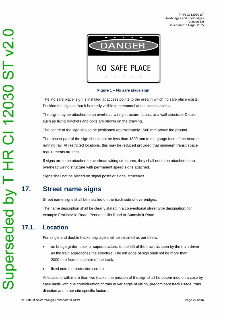
Figure 1 – No safe place sign
The ‘no safe place’ sign is installed at access points to the area in which no safe place exists.
Position the sign so that it is clearly visible to personnel at the access points.
The sign may be attached to an overhead wiring structure, a post or a wall structure. Details
such as fixing brackets and bolts are shown on the drawing.
The centre of the sign should be positioned approximately 1500 mm above the ground.
The closest part of the sign should not be less than 1800 mm to the gauge face of the nearest
running rail. At restricted locations, this may be reduced provided that minimum transit space
requirements are met.
If signs are to be attached to overhead wiring structures, they shall not to be attached to an
overhead wiring structure with permanent speed signs attached.
Signs shall not be placed on signal posts or signal structures.
17. Street name signs Street name signs shall be installed on the track side of overbridges.
The name description shall be clearly stated in a conventional street type designation, for
example Erskineville Road, Pennant Hills Road or Sunnyholt Road.
17.1. Location For single and double tracks, signage shall be installed as per below:
• on bridge girder, deck or superstructure: to the left of the track as seen by the train driver
as the train approaches the structure. The left edge of sign shall not be more than
2000 mm from the centre of the track.
• fixed onto the protection screen
At locations with more than two tracks, the position of the sign shall be determined on a case by
case basis with due consideration of train driver angle of vision, predominant track usage, train
direction and other site specific factors. © State of NSW through Transport for NSW Page 29 of 36
Sup
erse
ded
by T
HR
CI 1
2030
ST
v2.0

T HR CI 12030 ST Overbridges and Footbridges
Version 1.0 Issued date: 14 April 2015
17.2. Fixing details Suitable fixing details shall be designed for each location.
17.3. Front details The stencilling details for the text shall be as per below:
• black lettering
• white background
• font type in accordance with AS 1744; Series E with medium spacing
• font size of 200 mm
At locations where vandalism may be an issue, signs shall have an anti-graffiti coating applied.
Figure 2 shows a typical configuration of a street sign.
Figure 2 – Typical configuration of a street name sign
17.4. Manufacturing details Signs shall be manufactured from the following high strength, corrosion resistant aluminium of
the grades listed below:
• extrusions: grade 6063 T6 or grade 6061 T6 to in accordance with AS/NZS 1734
Aluminium and aluminium alloys – Flat sheet, coiled sheet and plate
• sheet: grade 5251 H38 to in accordance with AS/NZS 1734
The sheet metal used to manufacture the sign shall be 2 mm thick
The material on the sign shall be retro reflective material in accordance with AS 1906.1
Retroreflective materials and devices for road traffic control purposes – Retroreflective
materials.
© State of NSW through Transport for NSW Page 30 of 36
Sup
erse
ded
by T
HR
CI 1
2030
ST
v2.0

T HR CI 12030 ST Overbridges and Footbridges
Version 1.0 Issued date: 14 April 2015
Appendix A RMS Bridge Technical Directions The following RMS Bridge Technical Directions are relevant to overbridges and footbridges on
the TfNSW heavy rail network:
• BTD 2012/01 Provision of Safety Screens on Bridges
• BTD 2011/07 RTA Interim Code for Concrete Design
• BTD 2010/03 Pretensioned Bridge Members – Concrete Transfer Strength Requirements
• BTD 2008/17 Changes to Standard Bridge Drawings – RC Link Slab for Super T Girder
Decks
• BTD 2008/15 Concrete Parapets on Pedestrian Overbridges
• BTD 2008/14 Changes to Standard Bridge Drawings – Spaced Planks – Standard
Drawings
• BTD 2008/09 Link Slabs for Precast Pretensioned Concrete Girder Bridges
• BTD 2008/08 Provision of Conduits in Bridge Traffic Barriers
• BTD 2008/06 Joints in Precast Concrete Barrier Elements on a Grade
• BTD 2007/08 Rev1 Design of Replacement Traffic Barriers on Existing Bridges
• BPC 2005/09 Provision of Disabled Access for Pedestrian Bridges
• BPC 2004/10 Bridge Approach Slabs – Standard Drawings
• BPC 2003/02 Waterproofing Membranes for Concrete Bridge Decks
• BPC 2002/05 Bridge Concept
© State of NSW through Transport for NSW Page 31 of 36
Sup
erse
ded
by T
HR
CI 1
2030
ST
v2.0

T HR CI 12030 ST Overbridges and Footbridges
Version 1.0 Issued date: 14 April 2015
Appendix B Guidance regarding compliance of refurbishment works
Major refurbishment activity that triggers the requirement to upgrade an existing structure to
comply with this standard is defined as work which satisfies both of the criteria below:
• the work is considered as being structural including:
o widening the bridge
o extending bridge by the addition of a span
o replacing the superstructure only
o replacing the substructure only
o strengthening the bridge
o adding canopies or barriers
• the estimated cost of the refurbishment work is greater than 35% of the replacement cost
of the existing structure with a new, compliant structure
The replacement of the structure could be a more sustainable option than upgrading the
existing structure.
For a footbridge, the structure includes all associated ramps and stairways in addition to the
bridge.
Major refurbishment does not include the removal of components, without their replacement,
such as ramps, stairways and bridge span(s).
New structures, such as lifts, built adjacent to existing structure that do not rely on that existing
structure for support or do not provide support to that existing structure, do not trigger the
requirement to upgrade that existing structure. However, the associated changes in usage
might require upgrading of the existing structure, in accordance with criteria above.
Refurbishment works adjacent to an existing structure shall take into account the need to
develop or replace the existing structures in the future.
© State of NSW through Transport for NSW Page 32 of 36
Sup
erse
ded
by T
HR
CI 1
2030
ST
v2.0
T HR CI 12030 ST Overbridges and Footbridges
Version 1.0 Issued date: 14 April 2015
Appendix C Guard rails The primary function of derailment containment devices on rail tracks is to keep derailed or
derailing bogies tracked parallel to and in close proximity to the running rails. In the case of an
overbridge or footbridge, guard rails provide a level of protection to an at risk support or element
so that in the event of a train derailment, the superstructure does not collapse.
Where the hazard exists on one side of a concrete track slab, a single guard rail can be
provided for that side only. Single guard rails shall not be used on ballasted track.
When considering guard rails for a site, it is necessary to confirm that in the event of a
derailment, when restrained by the guard rails, the derailed vehicle will be clear of the structure.
Guard rails shall not be used to provide additional risk mitigation for structures that comply with
collision loads specified in TfNSW standards.
C.1. Configuration details The normal arrangement comprises two parallel guard rails (twin guard rails) with a tapered
‘vee’ section on the train approach side. Standard details for single guard rail installations have
not been developed at this stage. Details for single guard rail installations shall be approved by
the Lead Civil Engineer, ASA.
Where guard rails are determined to be appropriate to provide protection to at risk supports of
overbridges or footbridges, they shall be installed in accordance with the following
requirements:
• the guard rail shall be new rail manufactured to AS 1085.1 Railway track material – Part 1:
Steel rails or recycled rail Category 1 (white rail) in accordance with ESC 220 Rail and Rail
Joints
• the guard rail section shall be the same section size as the running rail or one section size
less than the running rail
• the top of guard rail shall be no higher than the adjacent running rail and no more than
50 mm below the running rail
• each guard rail shall be plated and fastened on both sides to every sleeper. ‘A’ clips shall
be used for fastening the sleeper.
• guard rails shall extend parallel for a minimum 20 metres in advance of the vulnerable
support on the train approach side
• the guard rails shall extend parallel for a minimum of 3 metres beyond the vulnerable
support on the train departure side
© State of NSW through Transport for NSW Page 33 of 36
Sup
erse
ded
by T
HR
CI 1
2030
ST
v2.0

T HR CI 12030 ST Overbridges and Footbridges
Version 1.0 Issued date: 14 April 2015
• a tapered nose section (‘vee’), with a minimum length of 3.6 metres shall be installed on
the train approach side of the guard rail
• where rail traffic is bi-directional, the guard rail shall extend 20 metres beyond the
vulnerable support on both approach and departure sides
• where rail traffic is bi-directional, the tapered nose section shall be installed at both ends
• the clearance between the gauge face of the running rail and adjacent face of guard rail
shall be 380 mm
• block-out holes for guard rail fastenings in concrete sleepers shall be grouted with an
approved high strength grout
The details contained in the standard drawings listed below may be adopted for guard rails on
ballasted track:
• CV 0179048 Guard Rails Installation of Guard Rails on Ballast Top Underbridge General
Arrangement
• CV 0179050 Guard Rails Installation of Guard Rails on Ballast Top Underbridge Details of
Guard Rail Concrete Sleepers
• CV 0179051 Guard Rails Installation of Guard Rails on Ballast Top and Transom Top
Underbridges Detail of Tapered Nose Section
• CV 0558906 Typical Details – All Lines – Combined ALT 1 & Guard Rail Plate – Details
These drawings show the dimensional set-out, detail and sizes for componentry, and fixing
details for twin guard rails for ballast top concrete sleepered underbridges.
C.2. Signalling interface Suitable isolation arrangements shall be made, where required, in track circuited and electrified
areas.
The tapered nose section (‘vee’) shall be insulated with an approved component. Figure 3
shows a typical configuration. This insulation requirement applies to new installations and where
refurbishment of the guard rails is undertaken.
© State of NSW through Transport for NSW Page 34 of 36
Sup
erse
ded
by T
HR
CI 1
2030
ST
v2.0

T HR CI 12030 ST Overbridges and Footbridges
Version 1.0 Issued date: 14 April 2015
Figure 3 – Signalling interface insulation
Where guard rails exceed 50 metres in length, additional insulation and bonding arrangements
may be required. Design drawings shall specify that insulation and bonding arrangements and
shall be in accordance with the requirements of the Lead Signals and Control Systems
Engineer, ASA. For further information, refer to ESG 100.17 Signal Design Principles Track
Circuits.
C.3. Joints in guard rails Guard rails on track adjacent to supports of an overbridge or footbridge may have minimal joints
with at least two bolts on each side.
If standard fishplates are used, six bolts are required.
If modified fishplates are used, the four bolts shall have all the nuts on the inside. Fishplates
shall be modified by machining, not by oxy-acetylene cutting. The plates shall have slotted
holes for the bolts.
No joints, other than insulated joints, are permitted in the vee.
C.4. Automatic Train Protection interface Advice shall be sought from the TfNSW Automatic Train Protection (ATP) project team on
guidelines for suitable interface arrangements where ATP balises are installed or where they
are proposed to be installed. The final arrangement shall be approved by the Lead Civil
Engineer, ASA.
© State of NSW through Transport for NSW Page 35 of 36
Sup
erse
ded
by T
HR
CI 1
2030
ST
v2.0
T HR CI 12030 ST Overbridges and Footbridges
Version 1.0 Issued date: 14 April 2015
Appendix D Aesthetic considerations and guidelines
The final appearance and aesthetic qualities of a bridge should be an important consideration in
the design process. Bridge structures shall be designed to be functional, safe and economical
over their life cycle. Another important design objective is to make them look visually appealing.
The overall form of a bridge should have a pleasing appearance and should also look
appropriate for its specific location.
Designs for bridge structures should be considered in relation to environmental context.
Sensitive contextual design involves being responsive to a particular setting. It is not enough for
structures merely to look inoffensive, they should be required to make a positive visual
contribution to their surroundings.
Bridges should not only have adequate strength for their purpose, they must also appear to
have structural integrity. A bridge should not only express its structural form, it should be
physically and visually coherent, having an ordered relationship between the various component
parts and the whole composition. There should be overall visual unity and a degree of
consistency between bridge elements and materials, and the design details for all of the
individual components and their connections, junctions, corners and so on shall be well-
resolved.
Creating structures that look good is not simply a matter of taste. Positive visual quality is the
result of a design process where careful thought is given to the basic aesthetic principles of
scale, form, proportion, order, balance, rhythm, and harmony, from the outset. Simplicity or
complexity of structural form, and other aesthetic design considerations such as pattern, colour,
contrast and texture also contribute to how a structure will be perceived.
Thinking about how a bridge might look throughout its whole life cycle (that is, over the short,
medium and long term future) should be an important part of the design process. Structures
should be designed to weather and age gracefully so that the potential unsightly effects of
staining, discoloration and vegetation growth can be controlled. Specification of quality materials
and surface finishes in combination with good workmanship during construction will help to
maintain the aesthetic character of a structure and keep it looking attractive for a long time.
Additional guidance can be found in the RMS publication, Bridge Aesthetics – Design guidelines
to improve the appearance of bridges in NSW.
© State of NSW through Transport for NSW Page 36 of 36
Sup
erse
ded
by T
HR
CI 1
2030
ST
v2.0