Embed Size (px)
Citation preview
3G EvolutionChapter: 16p 16
Donwlink TransmissionDonwlink Transmission Scheme
Department of Electrical and Information Technology
The Date 3G Evolution - HSPA and LTE for Mobile Broadband 1
Outline
• LTE Time-Frequency structure
• Downlink L1/L2 control signaling/processing
• Downlink transport channel processing
• Multi-Antenna transmission
• MBSFN transmission
The Date 3G Evolution - HSPA and LTE for Mobile Broadband 2
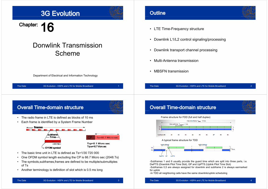
Overall Time-domain structure
• The radio frame in LTE is defined as blocks of 10 msE h f i id tifi d b S t F N b• Each frame is identified by a System Frame Number
Th b i ti it i LTE i d fi d T 1/30 720 000• The basic time unit in LTE is defined as Ts=1/30 720 000• One OFDM symbol length excluding the CP is 66.7 Micro sec (2048.Ts)• The symbols,subframes,frames are defined to be multiple/submultiplesThe symbols,subframes,frames are defined to be multiple/submultiples
of Ts• Another terminology is definition of slot which is 0.5 ms long
The Date 3G Evolution - HSPA and LTE for Mobile Broadband 3
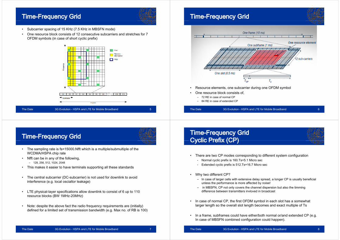
Overall Time-domain structure
Frame structure for FDD (full and half duplex)
A typical frame structure for TDD
-Subframes 1 and 6 usually provide the guard time which are split into three parts, i.e.y p g p p ,DwPTS (Downlink Pilot Time Slot), GP and UpPTS (Uplink Pilot Time Slot)-Subframes 0,5 are always assigned for downlink and subframe 2 is always earmarkedfor uplinkIn TDD all neighboring cells have the same downlink/uplink scheduling
The Date 3G Evolution - HSPA and LTE for Mobile Broadband 4
-In TDD all neighboring cells have the same downlink/uplink scheduling
Time-Frequency Grid
• Subcarrier spacing of 15 KHz (7.5 KHz in MBSFN mode)• One resource block consists of 12 consecutive subcarriers and stretches for 7• One resource block consists of 12 consecutive subcarriers and stretches for 7
OFDM symbols (in case of short cyclic prefix)
The Date 3G Evolution - HSPA and LTE for Mobile Broadband 5
Time-Frequency Grid
R l b i d i OFDM b l• Resource elements, one subcarrier during one OFDM symbol• One resource block consists of,
– 72 RE in case of normal CP– 84 RE in case of extended CP
The Date 3G Evolution - HSPA and LTE for Mobile Broadband 6
Time-Frequency Grid
• The sampling rate is fs=15000.Nfft which is a multiple/submultiple of the WCDMA/HSPA chip rateWCDMA/HSPA chip rate
• Nfft can be in any of the following,– 128, 256, 512, 1024, 2048
• This makes it easier to have terminals supporting all these standards• This makes it easier to have terminals supporting all these standards
• The central subcarrier (DC-subcarrier) is not used for downlink to avoid interference (e.g. local oscialtor leakage)
• LTE physical-layer specifications allow downlink to consist of 6 up to 110 p y y p presource blocks (BW 1MHz-20MHz)
• Note: despite the above fact the radio frequency requirements are (initially)• Note: despite the above fact the radio frequency requirements are (initially) defined for a limited set of transmission bandwidth (e.g. Max no. of RB is 100)
The Date 3G Evolution - HSPA and LTE for Mobile Broadband 7
Time-Frequency GridCyclic Prefix (CP)Cyclic Prefix (CP)
• There are two CP modes corresponding to different system configuration- Normal cyclic prefix is 160.Ts=5.1 Micro sec - Extended cyclic prefix is 512.Ts=16.7 Micro sec
• Why two different CP?– In case of larger cells with extensive delay spread, a longer CP is usually beneficialIn case of larger cells with extensive delay spread, a longer CP is usually beneficial
unless the performance is more affected by noise!– in MBSFN, CP not only covers the channel dispersion but also the timming
difference between transmitters invloved in broadcast
• In case of normal CP, the first OFDM symbol in each slot has a somewhat larger length so the overall slot length becomes and exact multiple of Tslarger length so the overall slot length becomes and exact multiple of Ts
• In a frame, subframes could have either/both normal or/and extended CP (e.g. In case of MBSFN combined configuration could happen)In case of MBSFN combined configuration could happen).
The Date 3G Evolution - HSPA and LTE for Mobile Broadband 8

Downlink Reference Signals(Pilots)(Pilots)
• To assist channel estimation reference signals are inserted at specific locations in each resource block
• Three types of reference signal distributions are defined for LTE,
– Cell specific downlink RS (Reference Signals) are inserted in every downlinkCell specific downlink RS (Reference Signals) are inserted in every downlink subframe and span the entire downlink cell BW
– UE-specific RS used in DownLink-Shared-CHannel (DL-SCH) and are intended forUE specific RS used in DownLink Shared CHannel (DL SCH) and are intended for specific terminals. They are transmitted in non-codebook-based beam forming where terminal is not aware of what precoding matrix has been applied to the data
– MBSFN reference signals, as evident from the name, are used in MBSFN transmission
The Date 3G Evolution - HSPA and LTE for Mobile Broadband 9
Cell-specific downlink RS
• The reference pilots are inserted assuming the full BW i e 110assuming the full BW, i.e. 110 resource blocks. Thus, the pilots in the central part of the band will always be the same fascilitatesalways be the same fascilitates decoding of BCH info
• Pilot pattern of each cell has a cell-specific configurationspecific configuration
• The depicted pattern is only one out of 6 possible frequency shifts of pilot patternspatterns
• each cell has a specific pilot pattern corresponding to its cell identityTh 504 ll id titi d fi d• There are 504 cell identities defined for LTE. Thus, each frequency shifted pilot pattern covers 84 different cell identitiesidentities
The Date 3G Evolution - HSPA and LTE for Mobile Broadband 10
Cell-specific downlink RS
• Smart assigning of pilot patterns in neighboring cells reduces the interference caused on the pilot positions assiged to each individual cell This becomescaused on the pilot positions assiged to each individual cell. This becomes specially handy when pilots are power boosted to fasciliated better channel estimation
• In the so called cell search procedure (Chapter 18) the terminal detects the physical cell identity as well as the begining of pilot sequences
• To determine the cell BW, BCH information (e.g. BW) is provided in the central part of BW where terminal does the channel estimation without having a prior k l d f ll BWknowledge of cell BW
The Date 3G Evolution - HSPA and LTE for Mobile Broadband 11
Cell-specific downlink RS-Multiple antenna portsantenna ports• LTE benefits from MIMO scheme
• In specifications the term antenna port is prefered over antenna since two/multiple physical antennas can transmit the same information and hence make one antenna port
• Each antenna port has a specific pilot pattern assigned to it. Thus, the terminal can estimate the downlink channel corresponding to each transmit antenna independantly
• The resource elements corresponding to pilots of each antenna port don’t carry any information for the resource blocks scheduled for other ports
• In case of 4 antenna ports the third and fourth antenna ports have less pilot density which comes with the following pros/cons,
– the reference signal overhead is reduced as an advantage– the channel estimation and tracking of channel variations degrades as a
consequenceNote: 4 antenna spatial multiplexing is usually used in low mobility scenarios!
The Date 3G Evolution - HSPA and LTE for Mobile Broadband 12

Cell-specific downlink RS-Multiple antenna portsantenna ports
The Date 3G Evolution - HSPA and LTE for Mobile Broadband 13
Cell-specific downlink RS-Multiple antenna portsantenna ports
The Date 3G Evolution - HSPA and LTE for Mobile Broadband 14
UE-specific downlink RS
• UE-specific transmission is referred to beam-formed transmission intended for a specific terminal/group of t i lterminals
• Just as data is beam-formed, pilots need also beamforming as a result of which UE-specific reference signals are created
• Transmission incompassing UE-specific RS is also called transmission using antenna port 5
• Piolts corresponding to antenna port 5 don’t collide with pilots transmitted on cell-specific RS
The Date 3G Evolution - HSPA and LTE for Mobile Broadband 15
UE-specific downlink RS
• The terminal is informed by the network if the DL SCH is done through cell• The terminal is informed by the network if the DL-SCH is done through cell-specific antenna ports or antenna port 5
• The beam forming is based on non-codebook configuration in which the base station doesn’t convey the precoding matrix to the UE/Ues
• Thus the terminal needs to know the channel experienced by the beamformed data
• The pilots will go through the same beamforming applied to data before transmitted to UE
The Date 3G Evolution - HSPA and LTE for Mobile Broadband 16

MBSFN-specific RS
• Specific subframes are allocated to carry MBSFN informationcarry MBSFN information
• Extended CP is used for MBSFN transmissionPiolt densit is higher in MBSFN• Piolt density is higher in MBSFN scheme due to higher frequency selectivity of the channelS ti l lti l i i t t d• Spatial multiplexing is not supported in MBSFN there is only one pilot patternPil t i i d• Pilot sequence is unique and no frequency shifted versions exist (compared to cell-specific pilot
tt )patterns)• MBSFN broadcast/multicast is also
known as antenna port 4 transmission
The Date 3G Evolution - HSPA and LTE for Mobile Broadband 17
Channel estimation
• UE needs to have proper knowledge(estimate) of the channel to decode the( )received data
• Interpolation/extrapolation techniques canp p qbe used for channel estimation of thoseresource elements not carrying any pilots
• Depending on the channel condition, e.g.amount of time dispersion, doppler shifts,etc. averaging can be done over multiplepilots in time/frequency to obtain a betterpilots in time/frequency to obtain a betterchannel estimate
• Due to limited computational power of UEDue to limited computational power of UEas well as low power requirements, lowcomplexity estimators are preferred whichmight not give the best results
The Date 3G Evolution - HSPA and LTE for Mobile Broadband 18
Downlink L1/L2 control signaling
• L1/L2 signaling originates from physical layer 1 and partly from MAC
•physical layer 1 and partly from MAC layer 2
• They are placed in the beginning of each subframeeach subframe
• L1/L2 signaling can occupy 1,2 or 3 OFDM symbols. Which size to assign depends on the traffic situation asdepends on the traffic situation as well as download transmission scheme
• There are many advantages to• There are many advantages to transmission of control signaling in the begining of each subframe,
The terminal for which the subframe is not– The terminal for which the subframe is not intended can enter idle mode and save power
– The sooner control signaling appears the li d di f d t i t tearlier decoding of data region starts
The Date 3G Evolution - HSPA and LTE for Mobile Broadband 19
Downlink L1/L2 control signaling
• In case of TDD subframes 1 and (GP) have a control region of length 2 OFDM• In case of TDD subframes 1 and (GP) have a control region of length 2 OFDM symbols. The third OFDM symbol constitutes the primary synchronization signal in those subframes
• In MBSFN, control region is confined to a maximum of 2 OFDM symbols (which is located in unicast part)
• L1/L2 control signaling can be divided into three different physical channel types,
– Physical Control Format Indicator Channel (PCFICH), infroming the terminal about the size of control region (unique in each cell)
– Physical Downlink Control Channel (PDCCH),used to signal downlink scheduling assignments and uplink scheduling grants. There are typically multiple PDCCHs per cell
– Physical Hybrid-ARQ Indicator Channel (PHICH), used to signal hybrid-AQR acknowledgments There are multiple PHICHs per each cellacknowledgments. There are multiple PHICHs per each cell
The Date 3G Evolution - HSPA and LTE for Mobile Broadband 20
Downlink L1/L2 control signalingResource element groupsResource element groups
• 4 consecutive resource elements make one resource element group• 4 consecutive resource elements make one resource element group• Considering the existence of scattered pilot signals, 2 resource element groups
can be mapped into the first OFDM symbol of each subframe
The Date 3G Evolution - HSPA and LTE for Mobile Broadband 21
(Downlink L1/L2 control signaling)Physical Control Format Indicator Channel (PCFICH)y ( )
• PCFICH indirectly indicates the beginning f d t i d h l th f 2 bitof data region and has a length of 2 bits
• It is coded in a 32-bit code word and scrambled with a cell/subframe specific scrambling code (which depends on thescrambling code (which depends on the physicall cell identity)
• Naturally It is always mapped to the first OFDM symbol of each subframe (since the y (size of control region is initially unknown)
• The four resource groups are well seperated in frequency (one quarter of BW
h) t id d f di iteach) to provide good frequnecy diversity• Starting position is defined by the physical
layer cell identity
The Date 3G Evolution - HSPA and LTE for Mobile Broadband 22
(Downlink L1/L2 control signaling)Physical Hybrid-ARQ Indicator Channel (PHICH)y y Q ( )
• The error rate restrictions on PHICH are much tougher than PCFICH. They are in the order of 1/10000 and are operator dependant as well
• The power is regulated by radio channel quality• For normal CP orthogonal sequences of length 4 are used while for extended CP
orthogonal codes of length 2 are applied. Excessive time dispersion in channel destroys orthogonality between the orthogonal codes In case of normal CP PHICH group size is 8 for ex CP it is 4• In case of normal CP PHICH group size is 8, for ex. CP it is 4
The Date 3G Evolution - HSPA and LTE for Mobile Broadband 23
(Downlink L1/L2 control signaling)Physical Hybrid-ARQ Indicator Channel (PHICH)y y Q ( )
• To fullfill frequency diversity PHICH is spread in frequncy grid (each resource group isTo fullfill frequency diversity, PHICH is spread in frequncy grid (each resource group is one third of BW away from its counter part)
• PHICH is (usually) mapped to the first OFDM symbol. Terminal will continue to decode even if it fails to decode PCFICH properly p p y
• In the first OFDM symbol, resources are first allocated to PCFICH, PHICH and PDCCH respectively
• To minimize the overhead, the PHICH group number, orthogonality sequence,etc. is determined by the number of the first resource block in which uplink transmission occured
• An uplink transport block received in subframe n should be confirmed through PHICH in subframe n+4. It is the same for TDD (taking the downlink-uplink configuration into account)account)
• PHICH configuration is determined through info provided by PBCH which is enough for FDD but not sufficient in case of TDD (because there is also a dependancy on the uplink/downlink configuration) 1 bit indicates if it is 1 or 3 OFDM symbols and 2 bitsuplink/downlink configuration). 1 bit indicates if it is 1 or 3 OFDM symbols and 2 bits indicate the amount of allocated resources (fraction of BW in terms of no. Res. Blocks)
• In case of TDD, the terminal has to blindly process PDCCHs under various PHICH configurations to be able to retrieve the necessary system information
The Date 3G Evolution - HSPA and LTE for Mobile Broadband 24

(Downlink L1/L2 control signaling)Physical Downlink Control Channel(PDCCH)y ( )
PDCCH is sed to transmit DCI s ch as• PDCCH is used to transmit DCI such as,– Donwlink scheduling assignments including:
• PDSCH resource indication• transport format• control information for spatial multiplexing• Commands for power control of PUCCH uplink physical channelCommands for power control of PUCCH uplink physical channel
– Uplink scheduling grants,• PUSCH resource indication• Transport formatTransport format• Hypbrid-ARQ related info• Command for power control of PUSCH uplink
Power control commands for a set of terminals on top of the above– Power control commands for a set of terminals on top of the above mentioned ones
The Date 3G Evolution - HSPA and LTE for Mobile Broadband 25
(Downlink L1/L2 control signaling)Physical Downlink Control Channel(PDCCH)y ( )
• DCI information comes in different message sizes for various configurations of the systemconfigurations of the system
• Message size depends on a number f f t BW f th ll t ffiof factors,e.g. BW of the cell, traffic,
etc.
• A multitude of various message types could be transmitted per subframe
The Date 3G Evolution - HSPA and LTE for Mobile Broadband 26
(Downlink L1/L2 control signaling)Physical Downlink Control Channel(PDCCH)y ( )
• Message type 1C,Random access response paging transmission of system information etc– Random access response, paging, transmission of system information, etc.
– QPSK only– No Hybrid-ARQ support
No closed loop spatial multiplexing– No closed-loop spatial multiplexing• Message type 1B,
– Frequnecy contiguous resource block assignment only (supports type 2)• Message type 1A,
– Supports codebook-based beamforming– Similar to 1B but bits for signaling of a precoding matrix are added– A flag indicates if it is 1A or DCI 0 which is used for uplink scheduling grants
• Message type 1,– Supports non-contiguous resource block allocations in frequencypp g q y
• Message type 2,– Similar to 1 but bits for indicating the number of transmission layers for spatial
multiplexing are providedp g p
The Date 3G Evolution - HSPA and LTE for Mobile Broadband 27
(Downlink L1/L2 control signaling)Signaling of resource block allocationsg g
• Different sig. is used to reduce the overhead of transmitting one big bitmap• Signaling for resource block allocation• Signaling for resource block allocation,
– Type 0– Type 1– Type 2Type 2
• In type 0 and type 1, the group size/subset size depends on the BW of the channel
The Date 3G Evolution - HSPA and LTE for Mobile Broadband 28
(Downlink L1/L2 control signaling)Physical Downlink Control Channel(PDCCH)y ( )
• Signaling for transport block sizes:• Signaling for transport block sizes:– provides information regarding modulation-coding scheme, block size– Integrated in 5 bits in different DCI message formats– There are 32 combinations,,
• 29 of them modulation-coding schemes• Three others are reserved for retransmission command purposes
• The modulation-coding scheme together with the number of resource blocks define the transport block size
• A mother table with 29 rows and 110 columns is created from which the desired transport block sizes will be extracted
• For BW narrower than 110 resource blocks, a subset of the table is used. If the cell BW is N the first N columns of the table are used
The Date 3G Evolution - HSPA and LTE for Mobile Broadband 29
(Downlink L1/L2 control signaling)Physical Downlink Control Channel(PDCCH)y ( )
The Date 3G Evolution - HSPA and LTE for Mobile Broadband 30
Uplink schedulink grants
• Uplink scheduling grants use DCI format 0 which is very similar to DCI format• Uplink scheduling grants use DCI format 0 which is very similar to DCI format 1A except one flag
A fl i 1A di t t if it i f li k d li k• A flag in 1A dictates if it is for uplink or downlink
• Neither spatial multiplexing nor noncontiguous resource block allocations are supported for a single terminal
• Resource block allocation type 2 is usedResource block allocation type 2 is used
• An uplink transmission grant recieved in donwlink subframe n is materialized in uplink subframe n+4 Compare with PHICHuplink subframe n+4. Compare with PHICH
The Date 3G Evolution - HSPA and LTE for Mobile Broadband 31
PDCCH processing
• CRC is calculated in conjunction with RNTI • Rate matching is used to adjust the rate toRate matching is used to adjust the rate to
the transmitted RB• To map the output from the rate matching
block a structure called Control Channel Elements (CCE) is used,
– A set of 36 resource elements 9 R. Groups– Number of CCE depends on the BW, size of
control region no of antenna ports as well ascontrol region, no. of antenna ports as well as the amount of resources occupied by PHICH
– Terminal needs to blindly decode the number of CCEs limited number of CCE aggregations for all possible PHICH config.aggregations for all possible PHICH config.
– Scrambling is done by a cell specific sequence to randomize the intercell interference
– Interleaving exploits the freq. DiversityCyclic shift is done to randomize the inter cell– Cyclic shift is done to randomize the inter cell intereferenec even more
Note: Terminal has to blindly decode the format of CCEs based on a search space defined and standardized in LTE
The Date 3G Evolution - HSPA and LTE for Mobile Broadband 32
pThe number of attempts is 44 times per subframe

Downlink transport-channel processing
• LTE physical layer interfaces to higherLTE physical layer interfaces to higher layers (MAC) through Transport Channels
• Similar to WCDMA/HSPA data are delivered to the Physical Layer in the form y yof transport blocks,
– Single antenna single block of dynamic sizeMultiple antennas up to 2 transport– Multiple antennas up to 2 transport blocks of dynamic size, each block corresponds to one code word in case of spatial multiplexing (even though up to 4 layers can be used for multiplexing still thelayers can be used for multiplexing still the no. of transport blocks in limited to 2)
– The processing chain is in many aspects similar to PCH and MCH
The Date 3G Evolution - HSPA and LTE for Mobile Broadband 33
Downlink transport-channel processing
• CRC has a length of a 24 bits Helps toCRC has a length of a 24 bits. Helps to detect errors and ask for retransmission of data
• In WCDMA both convolutional and turbo coding could be used. In HSPA as well as LTE only turbo coding is applied
• Scrambling sequences depend on the cell id tit d i d i ti fidentity and insure randomization of interference and help better decoding on terminal side
• QPSK 16QAM and 64QAM are supported• QPSK, 16QAM and 64QAM are supported in LTE
• The last stage (Resource block mapping ) maps the data for each antenna port to a p pset of available resource elements grouped as resource blocks
The Date 3G Evolution - HSPA and LTE for Mobile Broadband 34
Resource block mapping
• Data should be mapped to resource elements which are not reserved for pilot as well asData should be mapped to resource elements which are not reserved for pilot as well as synchronization signals
• Transmitter might consider channel conditions both in time and frequency to schedule the resource blocks for each UE which is not always advantagous. Thus, frequency diversity y g q y ywill be exploited by distributing the RB in whole BW
• Resource allocation types 0,1,2 can be used, yet– Due to certain limitations of type 0,1 type 2 is usually prefered
T h b tt f di t ib ti i f t 2 ti f Vi t l R Bl k (VRB) h b– To have a better frequency distribution in case of type 2, notion of Virtual Resource Blocks (VRB) has been introduced in LTE
• There are two different VRBs defined in LTE.Which one to use is declared to UE through PDCCHUE through PDCCH
The Date 3G Evolution - HSPA and LTE for Mobile Broadband 35
Resource block mapping
• Wether localized or distributed RB are usedWether localized or distributed RB are used will be indicated on the associated PDCCH in case of type 2
E i l bl k i ill b• Even a single resource block pair will be scattered in PRB
An example of mapping with 25 RB pairs
The Date 3G Evolution - HSPA and LTE for Mobile Broadband 36

Multi-Antenna transmission
• LTE supports the following multi antenna transmission schemes on top of single antennaLTE supports the following multi antenna transmission schemes on top of single antenna transmission,
– Transmit diversity• In case of two antenna ports diversity is achived through space frequency block coding (SFBC)
I if 4 t t b th SFBC ll F Shift T it Di it (FSTD) li d It• In case if 4 antenna ports, both SFBC as well as Frequency Shift Transmit Diversity (FSTD) are applied . It operates on groups of 4 resource elements per group resource element groups were defined
– Closed-loop spatial multiplexing including codebook-based beam-forming– Open-loop spatial multiplexing
The Date 3G Evolution - HSPA and LTE for Mobile Broadband 37
Multi-Antenna transmissionSpatial MultiplexingSpatial Multiplexing
• Spatial multiplexing means transmission of multiple streams (layers) in parallel• Spatial multiplexing means transmission of multiple streams (layers) in parallel
• In LTE the maximum number of layers is allowed to be 4 (number of antenna t )ports)
• Spatial Multiplexing has two forms in LTE,– Open-loop spatial multiplexing
• Used in high mobility scenarios and cases where the extra overhead of closed-loop multiplexing is not justified
• The precoding matrices are well-defined No information regarding the precoding matrix is transmitted to UE
– Closed-loop spatial multiplexing , • multiplexing relies on the feedback received from UE• The terminals need to provide both the Rank as well as the precoding matrix to
transmitter
The Date 3G Evolution - HSPA and LTE for Mobile Broadband 38
Multi-Antenna transmissionClosed-loop Spatial MultiplexingClosed loop Spatial Multiplexing• UE can report its desired precoding matrix (Rank
Indication) as well as number of layers to the transmitter. Transmitter doesn’t have to follow UE’s suggestion though
• One or two code words are always fed to the layer mapper. For a single antenna port, one y pp g pcode word (transport block) and for two or more antenna ports two code words are used
• Code word lengths are chosen in a way such that layers always have equal lengththat layers always have equal length
• Finally layers are precoded and mapped to the physical antenna ports through a precoding matrix WIn case of a single la er being mapped to a• In case of a single layer being mapped to a number of antenna ports, W is a column vector producing a beamformed output
The Date 3G Evolution - HSPA and LTE for Mobile Broadband 39
Multi-Antenna transmissioncodebook-based beam-formingcodebook based beam forming
The Date 3G Evolution - HSPA and LTE for Mobile Broadband 40

Multi-Antenna transmissionGeneral beam-formingGeneral beam forming
• Using codebook-based beam forming UE uses cell specific pilots to perform• Using codebook-based beam forming, UE uses cell specific pilots to perform the channel estimation
I f d b k b d b f i• In case of non-codebook based beam forming:
– UE has to use UE specific pilots for channel estimation
– The pilots have to go through the same beamforming experienced by data
– This transmission is also called transmission using antenna port 5
– It is only applicable in DownLink-SharedCHannel (DL-SCH)
The Date 3G Evolution - HSPA and LTE for Mobile Broadband 41
MBSFN transmission and MCH
• Multicast/Broadcast over Single Frequency Network• Multicast/Broadcast over Single Frequency Network• OFDM multi-cell multicast/broadcast a possibility• Transmissions from various cells to the terminal appear as comming from a
single node• -Benefits,
– Increased signal strength specially at the borders of the cellsg g p y– Reduced ineterference for there is no interference caused by neighboring
cells– Additional diversity since the radio channel consists of several transmittersAdditional diversity since the radio channel consists of several transmitters
beign geographically apart
MCH t t h l i d f MBFSN t i i Th d t• MCH transport channel is used for MBFSN transmission. They are mapped to special subframes where no other Downlink data is mapped to
The Date 3G Evolution - HSPA and LTE for Mobile Broadband 42
MBSFN transmission and MCH
• There is only one reference signal defined for MBSFN (for one antenna port)• There is only one reference signal defined for MBSFN (for one antenna port)
• Multi-antenna diversity is not supported. It is believed that the high frequency selectivity of the channel in itself provides enough diversity
• Since MCH is simultaneously targetting different mobile terminals, Hybrid ARQ y g g , yis not really applicable
• MCH transport format is the same for all involved transmittersMCH transport format is the same for all involved transmitters
• MCH scrambling is MBSFN area-specific and not cell-specific
The Date 3G Evolution - HSPA and LTE for Mobile Broadband 43
MBSFN transmission and MCHsubframe structuresubframe structure
• The subframe consists of two partsThe subframe consists of two parts
• Unicast part bears the cell specific pilot patternpattern
• Unicast is always two OFDM symbols in lengthg
• It has the same role the L1/L2 control region has for non-MBSFN transmission
• Due to the CP length difference between the first and second resource block, there is a gap (hole) in the subframe
The Date 3G Evolution - HSPA and LTE for Mobile Broadband 44

Questions?
The Date 3G Evolution - HSPA and LTE for Mobile Broadband 45


