Embed Size (px)
Citation preview

Outdoor PowerMAX SSPA System
Operations Manual
213663 REV C ECO 18521 01/19/2018
Teledyne Paradise Datacom Phone: (814) 238-3450 328 Innovation Blvd., Suite 100 Fax: (814) 238-3829 State College, PA 16803 USA Web: www.paradisedata.com Email: [email protected]

2 213663 REV C Operations Manual, Outdoor PowerMAX System
Teledyne Paradise Datacom, a division of Teledyne Wireless LLC, is a single source for high power solid state amplifiers (SSPAs), Low Noise Amplifiers (LNAs), Block Up Converters (BUCs), and Modem products. Operat-ing out of two primary locations, Witham, United Kingdom, and State College, PA, USA, Teledyne Paradise Datacom has a more than 20 year history of providing innovative solutions to enable satellite uplinks, battlefield communications, and cellular backhaul. Teledyne Paradise Datacom Teledyne Paradise Datacom Ltd. 328 Innovation Blvd., Suite 100 2&3 The Matchyns, London Road, Rivenhall End State College, PA 16803 USA Witham, Essex CM8 3HA England (814) 238-3450 (switchboard) +44 (0) 1376 515636 (814) 238-3829 (fax) +44 (0) 1376 533764 (fax) Information in this document is subject to change without notice. The latest revision of this document may be downloaded from the company web site: http://www.paradisedata.com. Use and Disclosure of Data The items described herein are controlled by the U.S. Government and authorized for export only to the country of ultimate destination for use by the ultimate consignee or end-user(s) herein identified. They may not be re-sold, transferred, or otherwise disposed of, to any other country or to any person other than the authorized ulti-mate consignee or end-user(s), either in their original form or after being incorporated into other items, without first obtaining approval from the U.S. government or as otherwise authorized by U.S. law and regulations. Proprietary and Confidential The information contained in this document is the sole property of Teledyne Paradise Datacom. Any reproduc-tion in part or as a whole without the written permission of Teledyne Paradise Datacom is prohibited. All other company names and product names in this document are property of the respective companies.
© 2015-2018 Teledyne Paradise Datacom Printed in the USA

Operations Manual, Outdoor PowerMAX System 213663 REV C 3
Table of Contents
Table of Contents ................................................................................................................ 3
Section 1: Overview ........................................................................................................... 11 1.0 Introduction ......................................................................................................... 11 1.1 Theory of Operation ............................................................................................ 11
1.1.1 Optional L-Band Input ........................................................................... 13 1.2 Specifications ...................................................................................................... 13 1.3 Inspection ............................................................................................................ 13 1.4 Shipment ............................................................................................................. 13 1.5 Safety Considerations ......................................................................................... 14
1.5.1 High Voltage Hazards ........................................................................... 14 1.5.2 High Current Hazards ............................................................................ 14 1.5.3 RF Transmission Hazards ..................................................................... 15 1.5.4 Electrical Discharge Hazards ................................................................ 15 1.5.5 High Potential for Waveguide Arcing ..................................................... 15
1.6 Waveguide Pressurization and Dehydration ....................................................... 16
Section 2: System Components ....................................................................................... 19 2.0 Introduction ......................................................................................................... 19 2.1 High Power Outdoor SSPA ................................................................................. 19
2.1.1 Installation of Unit .................................................................................. 20 2.1.2 Connectors ............................................................................................ 20
2.1.2.1 RF Input Port (J1) [Type N (F)] ................................................ 21 2.1.2.2 RF Output (J2) ........................................................................ 21 2.1.2.3 RF Output Sample Port (J3) [Type N (F)] ................................ 21 2.1.2.4 M&C Connector (J4) [MS3112E18-32S] .................................. 22 2.1.2.5 Link Port (J5) [MS3112E10-6S] ............................................... 23 2.1.2.6 Switch Port (J6) [MS3112E10-6S] ........................................... 23 2.1.2.7 AC Input Connector (J7) [MS3102E20-19P] ............................ 23 2.1.2.8 AUX PWR Port (J8) [MS3112E10-6S] ..................................... 24 2.1.2.9 Handheld Connector (J10) [MS3112E12-8S] .......................... 24 2.1.2.10 Chassis Ground Terminal ...................................................... 24 2.1.2.11 RF Input Sample Port (optional) [Type N (F)] ........................ 24
2.1.3 Physical Features .................................................................................. 25 2.1.3.1 Summary Alarm Indicator ........................................................ 25 2.1.3.2 Airflow and Removable Fan Trays ........................................... 25 2.1.3.3 Waveguide Pressure Window (option)..................................... 25
2.2 RF Distribution Panel & Power Detector Module ................................................ 26 2.2.1 RF Distribution Panel ............................................................................ 26
2.2.1.1 SSPA #.# RF Output (J1 through J8) ...................................... 26 2.2.1.2 RF Input (J9) ............................................................................ 26 2.2.1.3 RF Input Sample (J11) ............................................................. 27 2.2.1.4 RF Output Sample (J12) .......................................................... 27 2.2.1.5 Forward Sample In (J13) ......................................................... 27 2.2.1.6 Reflected Sample In (J14) ....................................................... 27

4 213663 REV C Operations Manual, Outdoor PowerMAX System
2.2.1.7 M&C Port (J15) ........................................................................ 27 2.2.1.8 Auxiliary Power In (J16) ........................................................... 27
2.2.2 Power Detector Module ......................................................................... 28 2.3 Outdoor System Controller .................................................................................. 29
2.3.1 Front Panel Interface ............................................................................. 29 2.3.2 I/O Connections ..................................................................................... 30
2.3.2.1 Ground Terminal ...................................................................... 30 2.3.2.2 Serial Main Port (J2) ................................................................ 30 2.3.2.3 Switch (SW) Port (J3) .............................................................. 30 2.3.2.4 Monitor & Control (M&C) Port (J4) ........................................... 30 2.3.2.5 DC Input Port (J5) .................................................................... 32 2.3.2.6 Auxiliary Power (AUX PWR) Port (J6) ..................................... 32 2.3.2.7 Parallel I/O Port (J7) ................................................................ 32 2.3.2.8 Link Port (J8) ........................................................................... 33 2.3.2.9 Ethernet Port (J9) .................................................................... 33
2.4 Ethernet Switch (Optional) .................................................................................. 34 2.4.1 Ethernet Switch Specifications .............................................................. 34 2.4.2 Ethernet Switch Connectors .................................................................. 35 2.4.3 Ethernet Mating Connectors .................................................................. 35
2.5 AC Distribution Box ............................................................................................. 36 2.6 1:1 Redundant Block Up Converter System (Optional L-Band Input) .................. 37
2.6.1 Hardware Setup .................................................................................... 37 2.6.2 vBUC Characteristics ............................................................................ 38
2.6.2.1 IFL Input Connector (J1) [Type N (F)] ...................................... 38 2.6.2.2 Monitor and Control Connector (J4) [MS3112E14-18S] .......... 38 2.6.2.3 1:1/Fiber Optic Connector (J5) [MS3112E12-10S] .................. 39 2.6.2.4 DC Input Connector (J7) [MS3102R18-4P] ............................. 40 2.6.2.4.1 Optional AC Power Supply ................................................... 40 2.6.2.5 Fan Power Connector (J8) [MS3112E8-3S] ............................ 40 2.6.2.6 RF Output ................................................................................ 41
Section 3: Installation of 8-Module System ..................................................................... 43
3.0 Introduction ......................................................................................................... 43 3.1 Unpacking and Inspection ................................................................................... 43 3.2 Installation ........................................................................................................... 43
3.2.1 Arrange Uni-Strut Frame Assemblies to Location Decking .................... 44 3.2.2 Install vBUC Redundant Plate Assembly (Optional) .............................. 45 3.2.3 Install Waveguide Switch Assembly ...................................................... 46 3.2.4 Install Termination Assembly ................................................................. 47 3.2.5 Install SSPA Controller/Ethernet Hub Assembly ................................... 48 3.2.6 Install RF Distribution Assembly ............................................................ 49 3.2.7 Install Optional AC Distribution Assembly ............................................ 50 3.2.8 Install High Power Outdoor SSPAs ....................................................... 51 3.2.9 Cable Connections ................................................................................ 52
3.2.9.1 System RF Input to RF Distribution Box .................................. 52 3.2.9.2 RF Coaxial Cable from RF Distribution Box to SSPAs ............ 52 3.2.9.3 Coaxial Cable between RF Dist. Box and Sample Ports ......... 53 3.2.9.4 Link Cable (L213828-1) ........................................................... 53 3.2.9.5 Switch Cable (L213829-1) ....................................................... 53

Operations Manual, Outdoor PowerMAX System 213663 REV C 5
3.2.9.6 Auxiliary Power Cable (L213830-1) ......................................... 54 3.2.9.7 Controller DC In Power Cables (L213826-1, -2) ...................... 55 3.2.9.8 Monitor & Control Cables (L213827-6, -7) ............................... 56 3.2.9.9 Controller Ethernet Cables (L213824-1) .................................. 57 3.2.9.10 Optional vBUC Ethernet Cables (L213825-1) ........................ 57 3.2.9.11 SSPA Power Cables .............................................................. 57
3.2.10 System RF Output Flange ................................................................... 58 3.2.11 System Prime Power .......................................................................... 58
Section 4: Local Operation ............................................................................................... 59
4.0 Outdoor Controller Menu Structure ..................................................................... 59 4.0.1 System Information Sub-Menu .............................................................. 60
4.0.1.1 Sys Info Page 1 ....................................................................... 61 4.0.1.1.1 Clear Faults Menu ...................................................... 61
4.0.1.2 Sys Info Page 2 ....................................................................... 61 4.0.1.3 Sys Info Page 3 ....................................................................... 62 4.0.1.4 Sys Info Page 4 ....................................................................... 62 4.0.1.5 Sys Info Page 5 ....................................................................... 62 4.0.1.6 Sys Info Page 6 ....................................................................... 63 4.0.1.7 Sys Info Page 7 ....................................................................... 63 4.0.1.8 Sys Info Page 8 ....................................................................... 63 4.0.1.9 Sys Info Page 9 (version 6.00) ................................................ 64 4.0.1.10 Sys Info Page 10 (version 6.00)............................................. 64 4.0.1.11 IP Info Page 1 ........................................................................ 65 4.0.1.12 IP Info Page 2 ........................................................................ 65 4.0.1.13 IP Info Page 3 ........................................................................ 65 4.0.1.14 IP Info Page 4 ........................................................................ 66 4.0.1.15 Firmware Info Page 1 ............................................................ 66 4.0.1.16 Firmware Info Page 2 (version 4.0) ........................................ 66 4.0.1.17 Firmware Info Pages 3, 4, 5 and 6 (version 4.0) .................... 66 4.0.1.18 Hardware Info Page 8 (version 6.00) ..................................... 66 4.0.1.19 HPA Local Time Page 9 (version 6.00) .................................. 67 4.0.1.20 HPA Run Time Page 10 (version 6.00) .................................. 67 4.0.1.21 N+1 Master Info Page 1 ......................................................... 67
4.0.1.21.1 Clear Faults Menu .................................................... 68 4.0.1.22 N+1 Slave Info Page .............................................................. 68
4.0.1.22.1 Clear Faults Menu .................................................... 68 4.0.1.23 N+1 Master Info Page 2 ......................................................... 68 4.0.1.24 N+1 Master Info Page 3 ......................................................... 69
4.0.2 Communication Setup Sub-Menu .......................................................... 69 4.0.2.1 Protocol ................................................................................... 69 4.0.2.2 Baud Rate ................................................................................ 70 4.0.2.3 System Address ....................................................................... 70 4.0.2.4 Interface ................................................................................... 70 4.0.2.5 IP Setup ................................................................................... 70
4.0.2.5.1 More (SNMP, IP and Web Settings) .......................... 71 4.0.2.5.2 More (Traps and Time Settings) ................................ 72
4.0.2.6 N+1 Control (Floating Master Mode) ....................................... 72 4.0.3 Operation Setup Sub-Menu ................................................................... 72

6 213663 REV C Operations Manual, Outdoor PowerMAX System
4.0.3.1 Info ........................................................................................... 74 4.0.3.2 Buzzer ..................................................................................... 74 4.0.3.3 Mute ......................................................................................... 74 4.0.3.4 Sys. Mode ................................................................................ 74 4.0.3.5 Attenuation .............................................................................. 75 4.0.3.6 RF Units ................................................................................... 75
4.0.4 Fault Monitoring Setup Sub-Menu ......................................................... 75 4.0.4.1 BUC Fault ................................................................................ 75 4.0.4.2 Auxiliary Faults ........................................................................ 76 4.0.4.3 RF Switch Faults ...................................................................... 76 4.0.4.4 Fault Latch ............................................................................... 76 4.0.4.5 Low RF / Automatic Level Control ........................................... 76
4.0.5 Options Sub-Menu ................................................................................ 77 4.0.5.1 Backup User Settings .............................................................. 78 4.0.5.2 Restore .................................................................................... 78 4.0.5.3 Lamp Test ................................................................................ 78 4.0.5.4 Password ................................................................................. 78 4.0.5.5 Fan Speed ............................................................................... 78 4.0.5.6 Reset ....................................................................................... 79
4.0.6 Redundancy Sub-Menu ......................................................................... 80 4.0.6.1 Switching ................................................................................. 80 4.0.6.2 Standby Select......................................................................... 80 4.0.6.3 Standby Mode.......................................................................... 80 4.0.6.4 Status ...................................................................................... 81 4.0.6.5 Priority ..................................................................................... 81 4.0.6.6 N+1 System Operation Parameters ......................................... 81
4.0.6.6.1 N+1 Array Size ........................................................... 81 4.0.6.6.2 N+1 Address .............................................................. 81 4.0.6.6.3 Auto Gain Control ...................................................... 81 4.0.6.6.4 N+1 Info ..................................................................... 82 4.0.6.6.5 Module Eject .............................................................. 83 4.0.6.6.6 Back ........................................................................... 83
4.1 N+1 Operational Basics ...................................................................................... 84 4.1.1 Selecting the Master Module ................................................................. 84 4.1.2 Controlling System Operation ................................................................ 85 4.1.3 N+1 Addressing ..................................................................................... 85 4.1.4 Adjusting System Gain .......................................................................... 85 4.1.5 N+1 Automatic Gain Control Option ...................................................... 85 4.1.6 Measuring N+1 RF Power ..................................................................... 86 4.1.7 N+1 Fault Detection ............................................................................... 86
4.2 Reflected Power Option ...................................................................................... 87 4.2.1 Reflected Power Alarm .......................................................................... 87
4.3 Characteristics of System Operation ................................................................... 88 4.3.1 System in 1:1 Redundant Mode with Array 2 in Standby ...................... 88 4.3.2 System in 1:1 Redundant Mode with Array 1 in Standby ...................... 89 4.3.3 Loss of a Controller ............................................................................... 89
Section 5: Remote Control Protocol, SSPA System ....................................................... 91
5.0 Overview ............................................................................................................. 91

Operations Manual, Outdoor PowerMAX System 213663 REV C 7
5.1 Remote Control - Parallel ................................................................................... 93 5.1.1 Control Outputs .................................................................................... 93 5.1.2 Control Inputs ....................................................................................... 93
5.2 Serial Communication Protocol ........................................................................... 94 5.2.1 Header Sub-Packet ............................................................................... 94
5.2.1.1 Frame Sync Word .................................................................... 94 5.2.1.2 Destination Address ................................................................. 94 5.2.1.3 Source Address ....................................................................... 94
5.2.2 Data Packet ........................................................................................... 95 5.2.2.1 Protocol ID ............................................................................... 95 5.2.2.2 Request ID ............................................................................... 95 5.2.2.3 Command ................................................................................ 95 5.2.2.4 Data Tag .................................................................................. 96 5.2.2.5 Error Status / Data Address ..................................................... 96 5.2.2.6 Data Length ............................................................................. 97 5.2.2.7 Data Field ................................................................................ 97
5.2.3 Trailer Packet ........................................................................................ 98 5.2.3.1 Frame Check ........................................................................... 98
5.2.4 Timing issues ........................................................................................ 98 5.2.5 Serial Communications Protocol ........................................................... 99
5.3 Access SSPA Subsystem through Packet Wrapper Technique ........................ 105 5.4 Example 1 Check SSPA settings ...................................................................... 106 5.5 Terminal Mode Serial Protocol for Paradise Datacom SSPA ............................ 108 5.6 Ethernet Interface .............................................................................................. 110
5.6.1 IPNet Interface .................................................................................... 110 5.6.1.1 General Concept .................................................................... 110 5.6.1.2 Setting IPNet interface ........................................................... 112 5.6.1.3 Using the Rack Mount Web Interface .................................... 113
5.6.2 SNMP Interface ................................................................................... 115 5.6.2.1 Interface ................................................................................. 115 5.6.2.2 SNMP V3 issues in Teledyne Paradise Datacom SSPAs ...... 115 5.6.2.3 SNMP MIB tree ...................................................................... 118 5.6.2.4 Description of MIB entities ..................................................... 119 5.6.2.5 Configuring RM SSPA unit to work with SNMP protocol ........ 124 5.6.2.6 Connecting to a MIB browser ................................................ 125
5.6.3 Extended SNMP Operation ................................................................. 127 5.6.3.1 Extended SNMP MIB Tree .................................................... 128 5.6.3.2 Extended SNMP MIB Tree Elements in Detail ....................... 130
Section 6: Remote Control Protocol, Optional Redundant vBUC System .................. 131
6.0 Overview ........................................................................................................... 131 6.1 Remote Control of vBUC System ...................................................................... 131 6.2 Serial Protocol Tables ....................................................................................... 131 6.3 SNMP Protocol Tables ...................................................................................... 131
Section 7: Troubleshooting & Maintenance .................................................................. 137 7.0 Troubleshooting ................................................................................................ 137
7.0.1 Identifying Amplifier Faults .................................................................. 137 7.0.1.1 N+1 Last Fault Address ......................................................... 137

8 213663 REV C Operations Manual, Outdoor PowerMAX System
7.0.1.2 Last Fault Display .................................................................. 138 7.0.1.3 N+1 Alarms ........................................................................... 138 7.0.1.4 N+1 State ............................................................................... 138
7.0.2 Common Fault Conditions ................................................................... 139 7.0.2.1 Summary Fault ...................................................................... 139 7.0.2.2 Voltage Fault ......................................................................... 139 7.0.2.3 Temperature Fault ................................................................. 139 7.0.2.4 Current Fault .......................................................................... 140 7.0.2.5 Power Supply Fault ................................................................ 140 7.0.2.6 Fan Fault ............................................................................... 140 7.0.2.7 Low RF Fault ......................................................................... 140 7.0.2.8 BUC Fault .............................................................................. 141
7.1 Periodic Inspection and Maintenance ............................................................... 142 7.1.1 Fan and Heatsink Cleaning ................................................................. 142 7.1.2 Controller Lamp Test ........................................................................... 143 7.1.3 Examine All Cables ............................................................................. 143
7.2 Default System Settings .................................................................................... 144 7.2.1 Automatic Restoration of Controller Settings ....................................... 144 7.2.2 Default IP Addressing .......................................................................... 144
Appendix .......................................................................................................................... 147
Figures
Figure 1-1: Simplified Block Diagram, 8-Way Outdoor PowerMAX System .............. 10 Figure 1-2: Degradation of Breakdown Power by VSWR .......................................... 15 Figure 2-1: Outline Drawing, Ku-Band H-Series High Power Outdoor SSPA ............ 19 Figure 2-2: Connectors at Bottom of Enclosure ........................................................ 20 Figure 2-3: RF Output Connector at Top of Enclosure .............................................. 21 Figure 2-4: RF Distribution Panel .............................................................................. 26 Figure 2-5: Outdoor System Controller Front Panel Interface and I/O Connectors ... 29 Figure 2-6: Controller Front Panel Interface .............................................................. 30 Figure 2-7: Outline Drawing, 105M12 Ethernet Switch ............................................. 34 Figure 2-8: Ethernet Switch Power (Left) and COMs (Right) Port Pin-outs ............... 35 Figure 2-9: AC Distribution Box, External and Interior Views .................................... 36 Figure 2-10: 1:1 Redundant System with 1:1 Cable Installed ................................... 37 Figure 2-11: Input/Output Connectors, Ku-Band vBUC ............................................. 38 Figure 3-1: Arrange Uni-Strut Frame Assemblies on Decking .................................. 44 Figure 3-2: Install Uni-Strut Support for vBUC Redundant Plate Assembly .............. 45 Figure 3-3: Install vBUC Redundant Plate Assembly ................................................ 45 Figure 3-4: Redundant BUC Plate, Installed ............................................................. 46 Figure 3-5: Install Waveguide Switch Assembly ....................................................... 46 Figure 3-6: Install Termination Assembly Below vBUC Plate Assembly ................... 47 Figure 3-7: Installation, SSPA Controller/Ethernet Hub Assembly ........................... 48 Figure 3-8: Installation, RF Distribution Assembly ................................................... 49 Figure 3-9: Installation, AC Distribution Assembly .................................................... 50 Figure 3-10: Installation, High Power Outdoor SSPAs .............................................. 51 Figure 3-11: Link Cable (L213828-1) ........................................................................ 53 Figure 3-12: Switch Cable (L213829-1) .................................................................... 53 Figure 3-13: Auxiliary Power Cable (L213830-1) ...................................................... 54

Operations Manual, Outdoor PowerMAX System 213663 REV C 9
Figure 3-14: Controller DC In Power Cables (L213826-1, -2) ................................... 55 Figure 3-15: Monitor & Control Cables (L213827-6, -7) ............................................ 56 Figure 3-16: Controller Ethernet Cables (L213824-1) ............................................... 57 Figure 3-17: vBUC Ethernet Cables (L213825-1) ..................................................... 57 Figure 3-18: System RF Output Flange .................................................................... 58 Figure 3-19: Prime Power Cable Access .................................................................. 58 Figure 3-20: Terminal Block Access.......................................................................... 58 Figure 4-1: Front Panel Menu Structure .................................................................... 59 Figure 4-2: System Information Sub-Menu ............................................................... 60 Figure 4-3: Slave Unit Display ................................................................................... 66 Figure 4-4: Communication Setup Sub-Menu ........................................................... 69 Figure 4-5: Operation Setup Sub-Menu .................................................................... 74 Figure 4-6: Fault Monitoring Setup Sub-Menu .......................................................... 75 Figure 4-7: Options Sub-Menu .................................................................................. 77 Figure 4-8: Redundancy Sub-Menu .......................................................................... 80 Figure 4-9: N+1 Info menu ........................................................................................ 82 Figure 4-10: 1:1 Phase Combined Mode .................................................................. 88 Figure 4-11: 1:1 Redundant Mode with Array 2 in Standby ....................................... 88 Figure 4-12: 1:1 Redundant Mode with Array 1 in Standby ....................................... 89 Figure 5-1: Remote Control Interface Stack .............................................................. 91 Figure 5-2: Parallel I/O Form C Relay ...................................................................... 93 Figure 5-3: Basic Communication Packet ................................................................. 94 Figure 5-4: Header Sub-Packet ................................................................................ 94 Figure 5-5: Data Sub-Packet ..................................................................................... 95 Figure 5-6: Trailer Sub-Packet .................................................................................. 98 Figure 5-7: Packet Wrapper technique .................................................................... 105 Figure 5-8: Terminal Mode Session Example ......................................................... 109 Figure 5-9: UDP Redirect Frame Example .............................................................. 111 Figure 5-10: Web Interface Login Window .............................................................. 113 Figure 5-11: RM SSPA Web Interface, Status Tab ................................................. 114 Figure 5-12: GetIF Application Parameters Tab ...................................................... 125 Figure 5-13: Getif MBrowser Window, with Update Data in Output Data Box ......... 125 Figure 5-14: Getif MBrowser Window, Setting settingValue.5 to a Value of ‘1’ ....... 126 Figure 7-1: SSPA Status LED ................................................................................. 139 Figure 7-2: Intake Fan Assembly and Power Connector (inset) .............................. 144 Figure 7-3: Remove Exhaust Fan ........................................................................... 145 Figure 7-4: Uncouple Power Plug ........................................................................... 145
Tables Table 1-1: PowerMAX Output Power Reduction ......................................................... 9 Table 1-2: Recommended Output Power Thresholds ............................................... 16 Table 1-3: De-rating of Popular W/G Components Relative to Straight W/G ............ 17 Table 2-1: Monitor & Control Connector (J4) Pin-Outs .............................................. 22 Table 2-2: Link Port (J5) Pin-Outs ............................................................................. 23 Table 2-3 Switch Port (J6) Pin-Outs .......................................................................... 23 Table 2-4: AC Input Connector (J7) Pin-Outs ........................................................... 23 Table 2-5: AUX PWR Port (J8) Pin-Outs ................................................................... 24 Table 2-6: Handheld Connector (J10) Pin-Outs ........................................................ 24 Table 2-7: RF Distribution Panel M&C Port (J15) ..................................................... 27

10 213663 REV C Operations Manual, Outdoor PowerMAX System
Table 2-8: RF Distribution Panel Auxiliary Power In Port (J16) ................................. 27 Table 2-9: Serial Main Port (J2) Pin-Outs ................................................................. 31 Table 2-10: Switch Port (J3) Pin-Outs ....................................................................... 31 Table 2-11: Monitor & Control Port (J4) Pin-Outs ..................................................... 31 Table 2-12: DC Input Port (J5) Pin-Outs ................................................................... 32 Table 2-13: AUX PWR Port (J6) Pin-Outs ................................................................. 32 Table 2-14: Parallel I/O Port (J7) Pin-Outs ................................................................ 32 Table 2-15: Link Port (J8) Pin-Outs ........................................................................... 33 Table 2-16: Ethernet Port (J9) Pin-Outs .................................................................... 33 Table 2-17: vBUC Monitor and Control Connector (J4) ............................................. 39 Table 2-18: 1:1/Fiber Optic Connector (J5) ............................................................... 39 Table 2-19: DC Input Connector (J7) ........................................................................ 40 Table 2-20: AC Power Supply Pin-outs ..................................................................... 40 Table 2-21: Fan Power Connector (J8) ..................................................................... 40 Table 5-1: Interfaces Enabled Based on Chosen Interface Setting Selection ........... 92 Table 5-2: Command Byte Values ............................................................................ 95 Table 5-3: Data Tag Byte Values .............................................................................. 96 Table 5-4: Error Status Byte Values .......................................................................... 97 Table 5-5: Request Frame Structure ......................................................................... 99 Table 5-6: Response Frame Structure ...................................................................... 99 Table 5-7: System Setting Details ........................................................................... 100 Table 5-8: System Threshold Addressing Details (Read Only) ............................... 102 Table 5-9: System Conditions Addressing Details .................................................. 103 Table 5-10: OSI Model for RM SSPA Ethernet IP Interface .................................... 111 Table 5-11: SNMP Detailed Settings....................................................................... 120 Table 5-12: SNMP Detailed Thresholds .................................................................. 122 Table 5-13: SNMP Detailed Conditions ................................................................... 123 Table 6-1: vBUC System Settings Data Values ...................................................... 132 Table 6-2: vBUC System Condition Addressing ...................................................... 133 Table 6-3: vBUC System Threshold Data Values ................................................... 134 Table 6-4: vBUC SNMP Detailed Settings .............................................................. 135 Table 6-5: vBUC SNMP Detailed Conditions .......................................................... 136 Table 6-6: vBUC SNMP Detailed Thresholds ......................................................... 136 Table 7-1: N+1 Address per System Amplifier Module ........................................... 137 Table 7-2: IP Addresses per System Amplifier Module ........................................... 144

Operations Manual, Outdoor PowerMAX System 213663 REV C 11
Section 1: Overview
1.0 Introduction The PowerMAX technology is the preeminent system technology in High Power Amplifier (HPA) redundancy. The Outdoor PowerMAX system architecture is a multi-module amplifier system. This allows PowerMAX systems to be configured with a large variety of output power levels. Furthermore, PowerMAX is a scalable amplifier system. A PowerMAX system may be initially configured with four modules, and later upgraded to eight modules in the field. This provides a tremendous protection of investment in the amplifier system. The system can grow with fu-ture power and bandwidth demands. 1.1 Theory of Operation PowerMAX is based on a purely parallel redundant, modular HPA system. It can be populat-ed with any number of modules between three and sixteen. For maximum RF efficiency it is recommended to power combine binary arrays of four, eight, or sixteen modules. A modular system is used either as an extremely high output power amplifier or as a self-redundant am-plifier system. Parallel architecture systems make excellent redundant systems. The PowerMAX system concept is parallel throughout all aspects of the design. The failure of a fan or system controller has no effect on the system operation. Full output power capability is maintained as well as remote communications and control of the amplifier system. The sys-tem will issue a minor alarm and indicate precisely which component has failed. The mainte-nance technician can then perform the replacement of the failed component without taking the system offline. This is referred to as hot-swap component replacement. When used as a self-redundant amplifier system, the PowerMAX should be configured such that there is one module’s worth of excess output power capacity. In this way a failure of one SSPA module will still allow the system to provide the minimum output power necessary. This type of architecture is referred to as n+1 redundant, meaning that there is one additional RF module then required for normal system operation. When configuring n+1 redundant system output power with binary array systems the output power guideline shown in Table 1-1 should be followed.
System Configuration Loss of One (1) Module Reduction in Output Power 4-Module 3 of 4 Modules Operating -2.4 dB 8-Module 7 of 8 Modules Operating -1.2 dB
16-Module 15 of 16 Modules Operating -0.6 dB
Table 1-1: PowerMAX Output Power Reduction

12 213663 REV C Operations Manual, Outdoor PowerMAX System
For maintenance purposes, the Outdoor PowerMAX system uses a combination of parallel power combining and traditional phase combining. The system is configured with one (1) sys-tem controller module for each four (4) amplifiers in the system. In systems with more than four (4) amplifiers, multiple controllers are used in a master/slave configuration. Each array of four amplifiers is structured in a parallel architecture redundant system. The RF outputs of each amplifier are phase combined to a single output. See the block diagram of Figure 1-1.
Each controller provides monitor and control capabilities for the four amplifiers to which it is connected. In systems with multiple controllers, one controller acts as the master, the other(s) are slave units to the master. The sophisticated firmware design of the PowerMAX permits the system to operate as if it were a single chassis amplifier. There is no need to communicate directly with each individual amplifier chassis. The system maintains a hierarchy of control whereby one of the system controllers becomes the master control point. If the master controller were to fail, control is automatically passed on to the next controller in the array. The firmware design also provides for power savings operation. Any number of the chassis can be placed in mute mode during periods in which full output power is not required. This will make significant savings in electricity costs required to operate the system. Otherwise, the system provides 20dB of gain adjustment in 0.1 dB increments as well as optional Automatic Level Control operation.
Figure 1-1: Simplified Block Diagram, 8-Way Outdoor PowerMAX System

Operations Manual, Outdoor PowerMAX System 213663 REV C 13
The system output power is measured with true rms power detection. Unlike peak detection circuits common in many HPA systems, true rms detection gives a very accurate measure-ment of the system’s output power in the presence of multiple carriers and modulation types. 1.1.1 Optional L-Band Input The Outdoor PowerMAX system may utilize an L-Band input by adding a 1:1 redundant block up converter system. The 1:1 Redundant BUC system is set at the factory, but may be monitored via computer from the Teledyne Paradise Datacom Universal M&C application. The Outdoor PowerMAX system controllers actively monitor the BUC system for faults and will communicate any fault conditions accordingly. 1.2 Specifications Refer to the specification sheet in the Appendix for complete specifications. 1.3 Inspection When the system is received, an initial inspection should be completed. First ensure that the shipping container is not damaged. If it is, have a representative from the shipping company present when the container is opened. Perform a visual inspection of the equipment to make sure that all items on the packing list are enclosed. If any damage has occurred or if items are missing, contact: Teledyne Paradise Datacom 328 Innovation Blvd., Suite 100 State College, PA 16803 USA Phone: +1 (814) 238-3450 Fax: +1 (814) 238-3829 1.4 Shipment To protect the system during shipment, use high quality commercial packing methods. When possible, use the original shipping container and its materials. Reliable commercial packing and shipping companies have facilities and materials to adequately repack the instrument.

14 213663 REV C Operations Manual, Outdoor PowerMAX System
1.5 Safety Considerations Potential safety hazards exist unless proper precautions are observed when working with this unit. To ensure safe operation, the user must follow the information, cautions and warnings provided in this manual as well as the warning labels placed on the unit itself. 1.5.1 High Voltage Hazards High Voltage, for the purpose of this section, is any voltage in excess of 30V. Voltages above this value can be hazardous and even lethal under certain circumstances. Care should be taken when working with devices that operate at high voltage.
• All probes and tools that contact the equipment should be properly insulated to prevent the operator from coming in contact with the voltage.
• The work area should be secure and free from non-essential items.
• Operators should never work alone on high voltage devices. There should always be another person present in the same work area to assist in the event of an emergency.
• Operators should be familiar with procedures to employ in the event of an emer-gency, i.e., remove all power, CPR, etc.
• An AC powered unit will have 115 VAC or 230 VAC entering through the AC power connector. Caution is required when working near this connector, the AC circuit breaker, or the internal power supply.
1.5.2 High Current Hazards Many high power devices are capable of producing large surges of current. This is true at all voltages, but needs to be emphasized for low voltage devices. Low voltage devices provide security from high voltage hazards, but also require higher current to provide the same power. High current can cause severe injury from burns and explosion. The following precautions should be taken on devices capable ofdischarging high current:
• Remove all conductive personal items (rings, watches, medals, etc.) • The work area should be secure and free of non-essential items. • Wear safety glasses and protective clothing. • Operators should never work alone on high risk devices. There should always
be another person present in the same area to assist in the event of an emer-gency.
• Operators should be familiar with procedures to employ in the event of an emer-gency, i.e., remove all power, CPR, etc.
Large DC currents are generated to operate the RF Module inside of the enclosure. EX-TREME CAUTION IS REQUIRED WHEN THE ENCLOSURE IS OPEN AND THE AMPLIFI-ER IS OPERATING. DO NOT TOUCH ANY OF THE CONNECTIONS ON THE RF MOD-ULES WHEN THE AMPLIFIER IS OPERATING. CURRENTS IN EXCESS OF 60 AMPERES MAY EXIST ON ANY ONE CONNECTOR.

Operations Manual, Outdoor PowerMAX System 213663 REV C 15
1.5.3 RF Transmission Hazards RF transmissions at high power levels may cause eyesight damage and skin burns. Pro-longed exposure to high levels of RF energy has been linked to a variety of health issues. Please use the following precautions with high levels of RF power.
• Always terminate the RF input and output connector prior to applying prime AC input power.
• Never look directly into the RF output waveguide • Maintain a suitable distance from the source of the trans-
mission such that the power density is below recommended guidelines in ANSI/IEEE C95.1. The power density specified in ANSI/IEEE C95.1-1992 is 10 mW/cm2. These require-ments adhere to OSHA Standard 1910.97.
• When a safe distance is not practical, RF shielding should be used to achieve the recommended power density levels.
1.5.4 Electrical Discharge Hazards An electric spark can not only create ESD reliability problems, it can also cause serious safety hazards. The following precautions should be followed when there is a risk of electrical dis-charge:
• Follow all ESD guidelines • Remove all flammable material and solvents from the area. • All probes and tools that contact the equipment should be
properly insulated to prevent electrical discharge. • The work area should be secure and free from non-
essential items. • Operators should never work alone on hazardous equip-
ment. There should always be another person present in the same work area to assist in the event of an emergency.
• Operators should be familiar with procedures to employ in the event of an emer-gency, i.e., remove all power, CPR, etc.
1.5.5 High Potential for Waveguide Arcing As with all systems which utilize high power signals within wave-guide, the potential exists for an electric arc to form. To minimize this risk, Teledyne Paradise Datacom requires all waveguide be pressurized and dehydrated.

16 213663 REV C Operations Manual, Outdoor PowerMAX System
1.6 Waveguide Pressurization and Dehydration When working with high power amplifier systems that operate into waveguide, the inadvertent creation of arcs is always a concern. An arc in waveguide is the air discharge breakdown due to the ionization of the air molecules by electrons. This breakdown in waveguide occurs when the rate of electron production becomes greater than the loss of electrons to diffusion to the surrounding walls. It is extremely difficult to precisely predict the power levels at which the breakdown occurs. It is dependent on a variety of factors but the primary factors are:
• Waveguide temperature and atmospheric pressure • Components in the Waveguide Transmission System such as: Flanges, Bends,
Tees, Combiners, Filters, Isolators, etc. • Load VSWR presented to the amplifier.
When operating such a high power amplifier system it is imperative that the waveguide trans-mission system be dehydrated and pressurized. Operation with an automatic air dehydrator will provide dry pressurized air to ensure that condensation cannot form in the waveguide. Al-so the higher the pressure that can be maintained in the waveguide; the higher the power handling is in the waveguide system. Most commonly available air dehydrators are capable of providing pressures of 0.5 to 7.0 psig (25-362 mmHg). At low power levels (uniform field distribution), low pressure can give good results. For non-uniform conditions, highly localized breakdown can occur. In this case the waveguide system will require much higher pressure. This occurs with bends, waveguide flange joints. If line cur-rents flow across a small gap introduced by poor tolerances, flange mismatch, poorly sol-dered bends, field strengths in excess of that in the main line can occur in the gap. Pressuri-zation with air or high dielectric gases can increase the power handling by factors of 10 to 100. In High Power Amplifier systems an arc will travel from where it is ignited back to the amplifi-er. Typical arc travel speed is on the order of 20 ft/sec. Increasing the waveguide pressure can reduce the speed of arc travel. It is difficult to get an accurate calculation of the amount of pressurization needed, but it is a good practice to get as much pressure as your system can handle. All high power systems that meet the criteria of Table 1-2 are pressure tested at the factory to 1.5 psig. As a guide we recommend using the power levels in Table 1-2 as the threshold levels where special attention be given to dehydration and the overall simplification of waveguide system design.
Satcom Band Frequency Range Amplifier Output Power Waveguide S Band 1.7-2.6 GHz > 10 kW WR430
C-Band 5.7 - 6.7 GHz > 2 kW WR137
X-Band 7.9-8.4 GHz > 1kW WR112
Ku-Band 13.75-14.5 GHz > 500W WR75
Ka-Band 27-31 GHz > 100W WR28
Table 1-2: Recommended Output Power Thresholds for Waveguide System Pressurization

Operations Manual, Outdoor PowerMAX System 213663 REV C 17
It is a common misconception to look up the maximum theoretical power handling of a partic-ular type of waveguide and assume that this is the maximum power handling. This may be the case for a straight waveguide tube with ideal terminations but these values must be signif-icantly de-rated in practical systems. Phase combined amplifier systems can be particularly sensitive to the potential for waveguide arcing. This is due to the numerous bends, magic tees, multiple waveguide flange joints, and other waveguide components. Table 1-3 shows the power handling capability of some popular waveguide components normalized to the waveguide power rating. From this table, we can see how a practical waveguide system’s power handling will de-rate significantly.
Most waveguide systems have many of these components integrated before reaching the an-tenna feed. It is not uncommon for a Satcom waveguide network to de-rate to 5% of the straight waveguide power rating. The load VSWR also has an impact on the breakdown threshold in waveguide networks. Standing waves degrade the power handling of any transmission line network. The graph of Figure 1-2 shows the rapid degradation of waveguide breakdown vs. load VSWR. The chart shows that for a 2.0:1 load VSWR, the breakdown potential will be half of what it would be with a perfectly matched load. This can degrade even more when high Q elements such as band pass filters are included in the waveguide network.
Waveguide Component Relative Power Rating H Plane Bend 0.6 to 0.9
E Plane Bend 0.97
90o Twist 0.8 to 0.9
Magic Tee 0.80
E-Plane Tee 0.06
H-Plane Tee 0.80
Cross Guide Coupler 0.21
Table 1-3: De-rating of Popular Waveguide Components Relative to Straight Waveguide
0.00
0.10
0.20
0.30
0.40
0.50
0.60
0.70
0.80
0.90
1.00
1 1.1
1.2
1.3
1.4
1.5
1.6
1.7
1.8
1.9
2 2.1
2.2
2.3
2.4
2.5
2.6
2.7
2.8
2.9
3.0Po
wer Degradatio
n Ratio
Load VSWR
Degradation of Breakdown Power by VSWR
Figure 1-2: Degradation of Breakdown Power by VSWR

18 213663 REV C Operations Manual, Outdoor PowerMAX System
There are many factors to consider with high power amplifier systems in terms of the output waveguide network. Especially when using HPA systems with output power levels of Table 1-2, it is imperative to ensure that the output waveguide network is pristinely clean and dry. An appropriate dehydrator should be used with capability of achieving adequate pressure for the system’s output power. Take extra precaution to make sure that any waveguide flange joints that are not already in place at the factory are properly cleaned, gasket fitted, and aligned. A properly designed and maintained waveguide network will ensure that no arcing can be supported and will provide many years of amplifier service life.

Operations Manual, Outdoor PowerMAX System 213663 REV C 19
Section 2: System Components
2.0 Introduction This section describes the various components that make up the Outdoor PowerMAX system. These include the High Power Outdoor SSPA enclosure, the RF Distribution Panel (which houses the Power Detector Module), the Outdoor System Controller, the optional Ethernet Switch, the optional AC Distribution Box, and the optional L-Band Input. 2.1 High Power Outdoor SSPA Figure 2-1 shows an outline drawing of a typical H-Series High Power Outdoor SSPA. The unit enclosure has overall dimensions of 27.5 inches (698.5 mm) by 16.5 inches (419.1 mm) by 9.335 inches (237.1 mm).
The enclosure is sealed to prevent water and debris intrusion, and has an ingress protection rating of IP54. A series of fans provides circulation of ambient air through the enclosure to cool the internal RF module. A status indicator is located above the intake fan panel. When the unit is operating normally, the status indicator illuminates green. If the unit enters a fault condition, the status indicator illuminates red. Fault conditions may be monitored remotely through the Monitor & Control connector (Port J4).
xx
Figure 2-1: Outline Drawing, Ku-Band H-Series High Power Outdoor SSPA

20 213663 REV C Operations Manual, Outdoor PowerMAX System
2.1.1 Installation of Unit When installing the H-Series High Power Outdoor SSPA, consider the following:
• There should be at least 8” clearance between the intake fans and any surface, and 8” clearance from the SSPA’s exhaust fans.
• The SSPA should never be enclosed in such a manner that restricts airflow. • Regular inspection and cleaning of the fans and heatsink is required. • Normal operating range of the SSPA is -40 to +60 °C • The unit will start up in a muted state. To unmute the amplifier, pins V and B of
Port J4 need to be shorted. The system cabling makes this connection. A series of mounting holes are located along the sides of the unit that include the lifting han-dles, and on the sides of the unit that include the intake and exhaust fans. If utilizing the mounting holes on the sides that include the fans, ensure the mounting brackets do not inter-fere with the air circulation into and out of the unit. The H-Series High Power Outdoor SSPA weighs between 100 and 140 lbs. (45.5 - 63.6 kg), depending on the power level of the unit. If mounting the unit to a boom or king post, ensure the mounting brackets and surface are capable of supporting the weight of the unit. At least two persons are required to lift the unit into position for mounting purposes. 2.1.2 Connectors Figure 2-2 and Figure 2-3 show the connectors available on the unit.
RF INPUT (J1)
RF INPUT SAMPLE
RF OUTPUT SAMPLE (J3) HANDHELD (J10)
SWITCH (J6)
LINK (J5)
SSPA STATUS AUX PWR (J8)
M&C (J4)
AC INPUT (J7) GROUND TERMINAL
Figure 2-2: Connectors at Bottom of Enclosure

Operations Manual, Outdoor PowerMAX System 213663 REV C 21
2.1.2.1 RF Input Port (J1) [Type N (F)] The Type N (F) connector shown at the top left of Figure 2-2 is the RF Input connector.
Warning! Maximum RF input that should be introduced at this connector is +15 dBm.
An optional L-Band input is available for units with an internal block up converter. 2.1.2.2 RF Output (J2) The RF Output shown in Figure 2-3 is a WR-75 waveguide flange with 0.206” diameter through holes, used with Ku-Band amplifiers. C-Band amplifiers utilize a CPRG-137 wave-guide flange with 0.206” diameter through holes. X-Band SSPAs use CPRG-112 waveguide flanges with 0.206” diameter through holes. S-Band amplifiers have Type N (F) connectors.
Warning! RF Hazards apply when power is applied to the unit. Do not operate the unit without having a termination or mating connection on the RF Output Port. Do not look directly into the RF Output waveguide.
2.1.2.3 RF Output Sample Port (J3) [Type N (F)] The Type N (F) connector at port J3 is the RF Output Sample port, and provides a coupled sample of the RF output signal. A calibration label is affixed next to this connector.
Figure 2-3: RF Output Connector at Top of Enclosure

22 213663 REV C Operations Manual, Outdoor PowerMAX System
2.1.2.4 M&C Connector (J4) [MS3112E18-32S] The Monitor and Control connector at Port J4 is a 32-pin MS-type circular connector. The pin-outs for this connector are shown in Table 2-1.
Table 2-1: Monitor & Control Connector (J4) Pin-Outs Signal Type Function Pin Notes
Mute Input Closure to Ground Disables DC Power to SSPA B Unit powers up muted;
This line must be pulled to ground (V) to enable amplifier
Auxiliary Input Closure to Ground Auxiliary Input P
Summary Alarm Form C Relay Closed on Fault
Common Open on Fault
L a b
L-a : normally open
a-b : normally closed
Auxiliary Alarm Form C Relay Closed on Fault
Common Open on Fault
N Z M
N-Z : normally open
Z-M: normally closed
Low RF Fault Output Open Collector High on Fault G Requires external pull-up
10 Base-T TX- W
See Section 8 10 Base-T RX- H
10 Base-T RX+ J
10 Base-T TX+ X
SSPA Spare Input Analog Input S +5V max.
Fan Fault Analog Output R
Gain Adjust Input Analog Input Adjusts Amplifier Gain over 20 dB range A 2.5 vdc = Max Gain 75 dB
0.5 vdc = Min Gain 55 dB
Block Up Converter Alarm Open Collector High on Fault f Requires external pull-up
RS232 / RS485 Select Closure to Ground Selects Serial Communication D Default is RS 485; pull to ground (d)
to enable RS 232
RS 485 TX- or RS232 OUT Serial TX Output Serial Link Data Port E
See Section 8 RS 485 RX- or RS232 IN Serial RX Input Serial Link Data Port F
RS 485 TX+ Serial TX Output Serial Link Data Port T
RS 485 RX+ Serial RX Input Serial Link Data Port U
GND Signal Ground Common Signal Return V Chassis ground
GND Signal Ground Isolated Comm Ground d Ground for Signals D, E, & F
Baud Select 0 Closure to Gnd Select Baud Rate & Protocol j Refer to Table 8-1
Baud Select 1 Closure to Gnd Select Baud Rate & Protocol e Refer to Table 8-1
PGM Switch Flash Firmware Port g Reserved for Programming
PGM CLK Flash Firmware Port c Reserved for Programming
PGM-Sout Flash Firmware Port K Reserved for Programming
PGM-Sin Flash Firmware Port Y Reserved for Programming
PGM +5V Flash Firmware Port h Reserved for Programming
PGM Enable Flash Firmware Port C Reserved for Programming

Operations Manual, Outdoor PowerMAX System 213663 REV C 23
The M&C connector contains a series of contact closures for monitoring amplifier faults as well as TVS protected inputs for controlling some amplifier functions. Inputs react on the closure to ground. Minimum closure time is 50mS. It requires a mating connector, MS3116F18-32P, which is supplied with the unit.
Note: The RF output of the internal amplifier module is disabled until the Mute Input (J4 – Pin B) is pulled to Ground (J4 – Pin V).
2.1.2.5 Link Port (J5) [MS3112E10-6S] The interface connector is used to connect two amplifiers when used in a 1:1 redundant system. It is a 6 pin circular connector, MS3112E10-6S. It requires a mating connector, MS3116F10-6P. A link cable is provided with a 1:1 Redundancy Kit, which can be purchased separately. See Table 2-2.
2.1.2.6 Switch Port (J6) [MS3112E10-6S] When used in a 1:1 redundant system, the waveguide switch must be connected to the switch port of each amplifier (MS3112E10-6S). See Table 2-3. It mates with MS3116F10-6P.
2.1.2.7 AC Input Connector (J7) [MS3102E20-19P] The prime power connector at Port J7 is a 3-pin MS-type connector, and provides universal AC input by using auto-sensing power supplies. The AC input can operate over a range of 180-265 VAC, at 47 to 63 Hz. See the product datasheet for power requirements for your model. The power supply is also power factor corrected, enabling the unit to achieve a power factor greater than 0.9. The pin-outs for this connector are shown in Table 2-4.
The amplifier has no on/off switch or circuit breaker in the AC Input path. As soon as power is applied to Port J7, the unit’s power supplies and microcontroller are enabled.
Table 2-2: Link Port (J5) Pin-Outs Pin # on J5 Connection Pin # on J5 Connection
A LINK OUT D N/C B LINK IN E N/C C N/C F GND
Table 2-3 Switch Port (J6) Pin-Outs Pin # on J6 Connection Pin # on J6 Connection
A N/C D N/C B N/C E POS 2 C +28 VDC F POS 1
Pin # on J7 Connection A L1
B GND
C L2/N
Table 2-4: AC Input Connector (J7) Pin-Outs

24 213663 REV C Operations Manual, Outdoor PowerMAX System
When power is applied, the operator will be able to observe the forced convection cooling fans spinning.
WARNING! Always terminate the RF input and output connectors prior to applying prime AC input power!
2.1.2.8 AUX PWR Port (J8) [MS3112E10-6S] The 6-socket MS-type female connector at this port is capable of supplying auxiliary power. This port is intended for use with factory-configured systems. Consult with the factory prior to making any connection to this port. Table 2-5 shows the pin outs for the AUX PWR Port (J8).
2.1.2.9 Handheld Connector (J10) [MS3112E12-8S] This port is used to connect to a RCH-1000 Universal Handheld Controller. The controller is shipped with a Communication Cable (L212640-2) which connects between the J10 connect-or of the amplifier and the eight-pin UltraLock connector of the RCH-1000. Table 2-6 shows the connector pin-outs for the Handheld Connector (J10).
See drawing number 211668 for operation instructions for the RCH-1000 Universal Handheld Controller. 2.1.2.10 Chassis Ground Terminal A chassis ground terminal is provided on the intake fan side of the amplifier. A 1/4-20 thread-ed terminal is provided for equipment grounding. 2.1.2.11 RF Input Sample Port (optional) [Type N (F)] This is a Type N (F) connector which provides a coupled sample of the RF Input. A calibration label is affixed to the enclosure next to this connector.
Table 2-5: AUX PWR Port (J8) Pin-Outs Pin # on J8 Connection Pin # on J8 Connection
A EXTERNAL FAULT IN D GND B FAULT PULLUP E +15V EXTERNAL C +15V LNA F GND
Table 2-6: Handheld Connector (J10) Pin-Outs Pin # on J10 Connection Pin # on J10 Connection
A RS-485 - E ENABLE B RS-485 + F GND C +15 VDC G N/C D N/C H N/C

Operations Manual, Outdoor PowerMAX System 213663 REV C 25
2.1.3 Physical Features In addition to the I/O connectors, the H-Series High Power Outdoor SSPA features include a summary alarm indicator and removable fan trays. 2.1.3.1 Summary Alarm Indicator A summary alarm indicator LED is located on the input side of the amplifier. When the SSPA is operating, this indicator illuminates GREEN. When in a fault condition, it illuminates RED. When an external mute signal is detected, the indicator will blink GREEN if operating, or RED if the amplifier is in a fault condition. 2.1.3.2 Airflow and Removable Fan Trays The H-Series High Power Outdoor amplifier’s cooling system represents a landmark in micro-wave telecommunication amplifiers. It features a unique system of heatsinks that have been computer optimized to provide extremely efficient cooling of all of the system’s functional blocks. The cooling system is based on a forced convection technique in which a series of fans provide the air intake and exhaust. A minimum clearance of 8 inches (203 mm) should be maintained between each fan tray and any mounting surface. This will ensure that there is no forced re-circulation of airflow from exhaust to intake. The fans should be examined periodically and any obstruction or debris should be cleared. Inadequate air flow can cause the amplifier to overheat and cause a temperature fault. See Section 7 for instructions on how to clean the fan trays and heatsink.
Notice: Failure to keep the heatsink and fans clear of debris will void the warranty on the unit.
In system configurations, ensure that each unit in the system has sufficient ambient airflow, and adequate space to maintain the fans for each unit. Spare fan assemblies are available from Teledyne Paradise Datacom. The intake fan assem-bly is part number L213271-1. The exhaust fan assembly is part number L213272-1, and there are two of these per amplifier. 2.1.3.3 Waveguide Pressure Window (option) Ku-Band units may be ordered with an optional waveguide pressure window at the RF Output (J2). This option is necessary for installations where the amplifier is connected to a pressur-ized transmission line (up to 15 PSI). All systems, regardless of operational band, include a pressure window at the system output bulkhead.

26 213663 REV C Operations Manual, Outdoor PowerMAX System
2.2 RF Distribution Panel & Power Detector Module Each system of four amplifiers is populated with a RF distribution panel which splits a single RF input signal to each of the amplifiers in the system. The RF Distribution Panel also pro-vides Input and Output sample ports for signal testing purposes. See Figure 2-4.
The RF Distribution Panel also houses the Power Detector Module, which is used to monitor the forward and reflected power. 2.2.1 RF Distribution Panel The RF Distribution Panel is a weather-resistant enclosure the splitters which provide each amplifier in the Outdoor PowerMAX system with the RF Input signal. The enclosure houses the phase adjusters and coaxial cable runs which have been delay matched to provide the signal to each amplifier at the same phase. 2.2.1.1 SSPA #.# RF Output (J1 through J8) These Type N (F) connectors are used to supply the RF signal to each of the amplifiers in the system. Connect a semi-rigid coaxial cable between these ports and the RF Input port (J1) of the appropriate amplifier. 2.2.1.2 RF Input (J9) This is a Type N (F) connector, and is where the RF Input signal is introduced to the system.
Figure 2-4: RF Distribution Panel

Operations Manual, Outdoor PowerMAX System 213663 REV C 27
2.2.1.3 RF Input Sample (J11) This is a Type N (F) connector and carries a sample of the RF Input signal. A label with cali-bration data is affixed near this connector. 2.2.1.4 RF Output Sample (J12) This is a Type N (F) connector and carries a sample of the RF Output signal. A label with cali-bration data is affixed near this connector. 2.2.1.5 Forward Sample In (J13) This Type N (F) connector is used to introduce a sample of the Forward RF signal to the pow-er detector module. 2.2.1.6 Reflected Sample In (J14) This Type N (F) connector is used to introduce a sample of the Reflected RF signal to the power detector module. 2.2.1.7 M&C Port (J15) This is a 6-pin circular MIL connector (MS3112E10-6P) which is used for serial communica-tion with the power detector module. See Table 2-7 for a pin-out of this connector.
2.2.1.8 Auxiliary Power In (J16) This is a 3-pin circular MIL connector (MS3112E8-3P) which is used to provide power to the power detector module. See Table 2-8 for a pin-out of this connector.
Power to the device is supplied over a cable connected to the Outdoor System Controller(s) Auxiliary Power Port (J6).
Pin # Connection A RS485+
B RS485-
C GND
Table 2-7: RF Distribution Panel M&C Port (J15)
Pin # Connection A +15V
B +15V
C GND
Table 2-8: RF Distribution Panel Auxiliary Power In Port (J16)

28 213663 REV C Operations Manual, Outdoor PowerMAX System
2.2.2 Power Detector Module The Teledyne Paradise Datacom RMS Power Detector Module is a companion product de-signed to operate in RF power amplifier systems where an external RF detector is required. The detector module allows simultaneous monitoring up to two independent RF detector channels and reports the monitored RF power value over the remote control interface. Chan-nel one (the main channel) is used for monitoring system forward RF power. Channel two is used for optional reflected power monitoring. Channel two can be turned off when not in use. The Detector Module was pre-configured at the factory and does not need any additional cali-bration.

Operations Manual, Outdoor PowerMAX System 213663 REV C 29
2.3 Outdoor System Controller This Outdoor System Controller is enclosed in a weather resistant powder-coated aluminum housing. The controller provides a single point of control for up to four (4) connected amplifi-ers. Multiple controllers can be connected in a master-slave configuration. 2.3.1 Front Panel Interface Figure 2-5 shows the front panel interface which is located beneath a hinged, weather-resistant door with a locking compression latch that seals the local control panel and sensitive electronics from the environment. The door is sealed against water intrusion by a heavy rub-ber gasket. Inspect this gasket periodically for tears or signs of leakage, and replace if neces-sary. Figure 2-5 also shows the Top Panel and Bottom Panel I/O Connectors.
Lifting the door of the Signal Box/System Controller enclosure reveals the local control panel. The local control panel includes a 40x2 display, ten (10) light emitting diodes, and nine (9) buttons.
Top Panel I/O Connectors
Bottom Panel I/O Connectors
Figure 2-5: Outdoor System Controller Front Panel Interface and I/O Connectors

30 213663 REV C Operations Manual, Outdoor PowerMAX System
The LEDs are used to indicate certain conditions of the system, and the presence of common system faults. Fault LEDs include:
• SUMMARY • VOLTAGE • TEMPerature • CURRENT • POWER SUPPLY
If a fault condition exists, the corresponding fault indicator will illuminate red. The Local/Remote button is adjacent to the LOCAL and REMOTE LEDs. Pressing the Local/Remote button toggles between the two choices. The LOCAL LED will illuminate when the system is in Local Mode. The RE-MOTE LED will illuminate when the system is in Remote Mode. The ONLINE button is adjacent to the ONLINE LED. The ONLINE LED will illumi-nate green when the system is Online. If the system is in Standby mode, the ONLINE LED will not be illuminated. The Mute/Unmute button is adjacent to the MUTE and UNMUTE LEDs. Pressing the Mute/ Unmute button toggles between the two modes. The MUTE LED will illuminate when the sys-tem is Muted. The UNMUTE LED will illuminate when the system is Unmuted. The Main Menu button is adjacent to the navigation buttons. The SSPA operational menu tree is accessed by pressing the Main Menu button. Navigation through the menu structure is handled by using the Up Arrow [▲], Down Arrow [▼], Left Arrow [◄], and Right Arrow [►] buttons and the Enter button to select from the menu items shown in the display. For menus where an actual numerical value must be entered, the Up Arrow [▲] and Down Arrow [▼] buttons change the number by factors of 10; the Left Arrow [◄] and Right Arrow [►] buttons change the number in increments of 1.
Note: If the Local/Remote button is toggled so that the Remote LED is illumi-nated, the Main Menu button, Arrow buttons and Enter button are disabled. Press the Local/Remote button so that the Local LED is illuminated to resume local operation.
See Section 4 for a description of the Local Control menu structure.
Figure 2-6: Controller Front Panel Interface

Operations Manual, Outdoor PowerMAX System 213663 REV C 31
2.3.2 I/O Connections Figure 2-5 shows the I/O Connections available on the top and bottom panels of the Outdoor System Controller. 2.3.2.1 Ground Terminal A 1/4–20 threaded terminal is provided for equipment grounding. 2.3.2.2 Serial Main Port (J2) The Serial Main Port (J2) is a 10-pin circular MIL type connector (MS3112E12-10P). See Ta-ble 2-9 for the pin-out for this connector.
2.3.2.3 Switch (SW) Port (J3) The Switch Port (J3) is a 6-socket circular MIL type connector (MS3112E10-6S). See Table 2-10 for the pin-out for this connector.
2.3.2.4 Monitor & Control (M&C) Port (J4) The Monitor & Control Port (J4) is a circular MIL type connector (PT02E-18-32S). See Table 2-11 for the pin-out for this connector.
Table 2-9: Serial Main Port (J2) Pin-Outs Pin # Connection Pin # Connection
A RS232 OUT / RS485 TX- F SERVICE REQUEST 2 B RS232 IN / RS485 RX- G SERVICE REQUEST COMMON C RS485 RX+ H 120 OHM TERMINATION D RS485 TX+ J GROUND E SERVICE REQUEST 1 K N/C
Table 2-10: Switch Port (J3) Pin-Outs Pin # Connection Pin # Connection
A +28 VDC D SW 2 POSITION 1 B +28 VDC E SW 1 POSITION 2 C SW 1 POSITION 1 F SW 2 POSITION 2
Table 2-11: Monitor & Control Port (J4) Pin-Outs Pin # Connection Pin # Connection
T RS485+ c SSPA2 FAULT E RS485- g SSPA3 FAULT B MUTE h SSPA4 FAULT V GROUND R FAN FAULT b SSPA1 FAULT

32 213663 REV C Operations Manual, Outdoor PowerMAX System
2.3.2.5 DC Input Port (J5) The DC Input Port (J5) is a 8-pin circular MIL type connector (MS3112E12-8P). See Table 2-12 for the pin-out for this connector.
2.3.2.6 Auxiliary Power (AUX PWR) Port (J6) The Auxiliary Power Port (J6) is a 4-socket circular MIL type connector (MS3112E8-4S). See Table 2-13 for the pin-out for this connector.
2.3.2.7 Parallel I/O Port (J7) The Parallel I/O Port (J7) is a 41-socket circular MIL type connector (MS3112E20-41S). See Table 2-14 for the pin-out for this connector.
Table 2-12: DC Input Port (J5) Pin-Outs Pin # Connection Pin # Connection
A +28 VDC E +15 VDC B +28 VDC F +15 VDC C N/C G GROUND D N/C H GROUND
Table 2-13: AUX PWR Port (J6) Pin-Outs Pin # Connection Pin # Connection
A +15 VDC C GROUND B +15 VDC (Ethernet Switch) D GROUND
Table 2-14: Parallel I/O Port (J7) Pin-Outs Pin # Connection Pin # Connection
A Power Supply Fault (closed on fault) W Current Fault (open on fault) B Power Supply Fault (open on fault) X Current Fault (common) C Power Supply Fault (common) Y Low RF Fault (closed on fault) D Auxiliary Fault (closed on fault) Z Low RF Fault (open on fault) E Auxiliary Fault (open on fault) a Low RF Fault (common) F Auxiliary Fault (common) b Mute Input (toggle on falling edge) G Mute Status (open on mute) c Local/Remote (toggle on falling edge) H Mute Status (closed on mute) d Auxiliary Fault Input J Mute Status (common) e Standby Select (falling edge detection) K BUC Fault (closed on fault) f Latched Fault Clear (falling edge det.) L BUC Fault (open on fault) g N/C M BUC Fault (common) h +28V Out N Temperature Fault (closed on fault) i Chassis Ground P Temperature Fault (open on fault) j +5 VDC Pull-up R Temperature Fault (common) k +28V Out S Regulator Fault (closed on fault) m Chassis Ground T Regulator Fault (open on fault) n Isolated Ground U Regulator Fault (common) p, q, r, s, t N/C V Current Fault (closed on fault)

Operations Manual, Outdoor PowerMAX System 213663 REV C 33
2.3.2.8 Link Port (J8) The Link Port (J8) is a 10-socket circular MIL type connector (MS3112E12-10S). See Table 2-15 for the pin-out for this connector.
2.3.2.9 Ethernet Port (J9) The Ethernet Port (J9) is a weatherized RJ45 bulkhead connector, with dust cover. See Table 2-16 for the pin-out for this connector.
Table 2-15: Link Port (J8) Pin-Outs Pin # Connection Pin # Connection
A RS485+ F SYNC B RS485+ G LINK IN A C RS485- H LINK IN B D RS485- J GROUND E LINK OUT K N/C
Table 2-16: Ethernet Port (J9) Pin-Outs Pin # Connection Pin # Connection
1 TX+ 5 GROUND 2 TX- 6 RX- 3 RX+ 7 GROUND 4 GROUND 8 GROUND

34 213663 REV C Operations Manual, Outdoor PowerMAX System
2.4 Ethernet Switch (Optional) Teledyne Paradise Datacom chose the 105M12 Industrial IP65 Rated Ethernet Switch for use with the Outdoor PowerMAX systems. It is designed to meet the most demanding industrial communications requirements while providing high throughput and minimum downtime. The 105M12 provides five (5) auto sensing 10/100BaseTX ports with M12, D-code, 4 pin (F) style connectors. All ports are full/half duplex capable. The switch auto-negotiates the speed and flow control capabilities of the five TX port connections, and configures itself automatical-ly. Since the switch is auto sensing, there will be no need to make extensive wiring changes if upgrades are made to the host microprocessors or Ethernet I/O modules. Figure 2-7 shows an outline drawing of the Ethernet Switch.
TX- RX-
TX+RX+
V1- V1+
V2+V2-
1 2
543
LNK/ACT
LNK/ACTLNK/ACTLNK/ACT
LNK/ACT
DIA.= 0.201"(TYPICAL)
DIA.= 0.140"(TYPICAL)
BACK PLATE 14 GAUGE304 STAINLESS STEEL
FRONT PLATE - 12 GAUGE304 STAINLESS STEEL
Figure 2-7: Outline Drawing, 105M12 Ethernet Switch
2.4.1 Ethernet Switch Specifications Electrical
• Input Voltage: 10-30 VDC • Steady Input Current: 215 mA @
24V • Inrush: 7.8 Amp / 0.7 ms @ 24V
Connectors • 10/100BaseTX: Five (5) M12
D-Coded 4-Pin Female Ports • Power: One (1) M12 A-Coded
5-Pin Male Port Network Media
• 10BaseT: > Cat3 Cable • 100BaseTX: > Cat5 Cable
Environmental
• Operating Temperature: -40 °C to 80 °C
• Storage Temperature: -40 °C to 85 °C
• Operating Humidity: 5% to 100% (Non Condensing)
• Operating Altitude: 0 to 10,000 ft. (3,000 m)
Reliability • MTBF: > 2 Million Hours

Operations Manual, Outdoor PowerMAX System 213663 REV C 35
2.4.2 Ethernet Switch Connectors The switch has an LED at each connector port. The LED adjacent to the Power port will illumi-nate when power is applied. The LEDs adjacent to the numbered COMs ports are the link/activity indicators. The LED will illuminate when a link is established, but there is no activity on the cable. It will blink when data is being transferred over the cable. The M12 A-coded, 5-pin (M) power connector is keyed, where the mating connection from the power supply can be made only when the male and female ends are properly aligned. When power is initially connected, all LEDs will illuminate momentarily. See Figure 2-8, left for the pin-outs of the power connector. The COMs ports are M12 D-coded, 4-pin (F) connectors and were shipped with IP67 caps installed to protect from dust and moisture ingress. The caps will need to be removed before connecting cables to the COMs port. See Figure 2-8, right for the pin-outs of the COMs con-nectors.
Warning: Connecting port-to-port on the Ethernet switch will create a feed-back loop. Do not connect port-to-port.
2.4.3 Ethernet Mating Connectors The Ethernet mating connectors used in the Outdoor PowerMAX system are M12 D-coded, straight, 4-pin (M), shielded plug connectors. If the operator plans to communicate remotely with the system over Ethernet, the cable connection to the Ethernet switch will need to use a M12 D-coded, straight 4-pin (M) shielded plug, such as those manufactured by Phoenix Con-tact, model SACC-M12MSD-4CON-PG 7-SH.
V1+
V2+
V1-
V2-
RX-
TX+
TX-
RX+Figure 2-8: Ethernet Switch Power (Left) and COMs (Right) Port Pin-outs

36 213663 REV C Operations Manual, Outdoor PowerMAX System
2.5 AC Distribution Box The AC Distribution Box is a convenient method of applying power to a single set of terminal blocks, which is then distributed to each of the system amplifiers and auxiliary equipment. The AC Distribution Box is a weatherized enclosure which houses the terminal blocks and a line out with breaker for each piece of equipment in the system. The hinged front access pan-el has two quarter-turn keyed latches which can be used to lock the panel closed. See Figure 2-9 [A]. Opening the front panel reveals a set of circuit breakers, one for each unit in the system. Each breaker is labeled to identify the equipment for which it applies. An access panel is secured by two screws. Removing the panel provides access to the cable conduit and termi-nal blocks. See Figure 2-9 [B]. At the rear panel, the Line In cable conduit features a 1.97” (50 mm) dome nut fitting which provides access for cable dimensions of 0.87” to 1.26” OD (22 to 32 mm). A secondary cable conduit may be used for the return line. It is a 0.94” (24 mm) dome nut fitting allowing access for cable dimensions of 0.39” to 0.55” OD (10 to 14 mm). A Line Out power cable for each unit in the system is connected to each circuit breaker, and run through weatherized access ports at the rear of the box. See Figure 2-9 [C]. Each power cable terminates in a connector. The power cables for the High Power Outdoor amplifiers have a circular MIL type connector (MS3106F20-19S), which plugs into the AC IN-PUT port (J7) of the amplifier. If the system includes the optional vBUC Redundant Plate Assembly, additional cables are available for each BUC in the converter system. The power cables terminate in a circular MIL type connector (MS3106F16-10S), which plugs into the AC IN port of the BUC Power Supply. All cables are labeled near the connector.
A B C
Keyed latches
Line out (x10)
Terminal Blocks
Circuit Breakers
Ground stud
Figure 2-9: AC Distribution Box, External and Interior Views

Operations Manual, Outdoor PowerMAX System 213663 REV C 37
2.6 1:1 Redundant Block Up Converter System (Optional L-Band Input) The vBUC converter is ideally suited for a self-contained and cost effective 1:1 redundant converter system. Each unit has a built-in 1:1 redundant controller. The 1:1 Redundant BUC system is pre-set at the factory, but may be monitored via computer from the Teledyne Para-dise Datacom Universal M&C application. The Outdoor PowerMAX system controllers active-ly monitor the BUC system for faults and will communicate any fault conditions accordingly. 2.6.1 Hardware Setup The hardware setup for a 1:1 Redundant BUC System is very simple and involves the addi-tion of a single cable along with a redundancy switch. A schematic diagram of the redundancy setup is shown in Figure 2-10.
The Link section of the cable is a simple, three conductor crossover cable that allows the sys-tem to pass command and control between units. The Switch section of the cable is a “T” configuration and connects between each unit and the redundancy switch. The Redundancy Switch is a -48 VDC type. The controller in each vBUC converter is capable of supplying +48 VDC to the common voltage input. Either vBUC may then provide a (sink) return to engage either position 1 or position 2 of the redundancy switch. Care must be observed when connecting this cable to the units. The cable end labeled “A1” must be connected to the unit whose output is connected to Port 3 of the waveguide switch. Likewise the cable end labeled “A2” must be connected to the unit whose output is connected to Port 1 of the waveguide switch. This is for proper identification purposes of the Redundan-cy Control Firmware used by each unit.
Figure 2-10: 1:1 Redundant System with 1:1 Cable Installed
AMP 1
AMP 2
L-BANDINPUT
RFOUTPUT
COAX WAVEGUIDE
SPLITTER
J5 - MS3112E12-10S
REDUNDANCYCABLE
J5 - MS3112E12-10S

38 213663 REV C Operations Manual, Outdoor PowerMAX System
2.6.2 vBUC Characteristics The vBUC converters are manufactured as two separate halves, the RF half and the DC half. The RF half features a newly designed IF/Synth board which improves the phase noise per-formance of the vBUC. The DC half has been redesigned to accommodate additional M&C functions including internal 1:1 redundancy and auxiliary power for an LNB or fiber-optic con-verter.
Figure 2-11 shows the input and output connectors of a typical Ku-Band vBUC converter. With the exception of the RF Output, the I/O connectors are the same for all vBUC converters regardless of the band or power level of the unit. 2.6.2.1 IFL Input Connector (J1) [Type N (F)] This connector is a Type N female connector, used to introduce an IFL signal, FSK Input and 10 MHz reference to the vBUC converter. Any DC current must be tapped off using an exter-nal Bias Tee. 2.6.2.2 Monitor and Control Connector (J4) [MS3112E14-18S] This connector is an 18-socket MS-type connector and is used to transmit and receive the monitor and control signals between the vBUC converter and a modem or computer. The pin-outs for this connector are shown in Table 2-17, shown on the following page. The mating connector is supplied with the unit, and is part number MS3116F14-18P.
Note: TX Inhibit (External Mute) must be grounded for the vBUC to operate.
Figure 2-11: Input/Output Connectors, Ku-Band vBUC
MODEL: XXXXXXXXXXXXP/N: LXXXXXX-X S/N: XXXX

Operations Manual, Outdoor PowerMAX System 213663 REV C 39
2.6.2.3 1:1/Fiber Optic Connector (J5) [MS3112E12-10S] This connector is a 10-socket MS-type connector and is used for internal 1:1 redundancy or when connected to a fiber optic converter. The mating connector is part number MS3116F12-10P. The pin-outs for this connector are shown in Table 2-18.
U Serial Communication RS-485 (-)
Table 2-17: vBUC Monitor and Control Connector (J4) PIN DESCRIPTION DETAILS
R Serial Communication RS-485 (+) L Serial Communication Isolated Ground B Summary Alarm Contacts Form C - Closed on Fault F Summary Alarm Contacts Form C - Common D Summary Alarm Contacts Form C - Open on Fault J TX Inhibit (External Mute) Ground to Enable TX H Ethernet TX - G Ethernet TX + C Ethernet RX - A Ethernet RX + E Ground Chassis Ground K Ground Chassis Ground M Ground Chassis Ground S Serial Override Ground to Enable Serial Comms N Ethernet Override Ground to Enable Ethernet Comms
PIN DESCRIPTION DETAILS J Fiber Optic Module Alarm Closure to Ground
Table 2-18: 1:1/Fiber Optic Connector (J5)
C Ground Ground H Ground Ground A +15 VDC for LNB Current Sensed +15 VDC B +15 VDC for Fiber Optic Module +15 VDC @ 1A G Redundancy Switch Drive +48 or +24 Current Sink E Link In F Link Out K Redundancy Switch Common +48 or +24 VDC (Vin+)

40 213663 REV C Operations Manual, Outdoor PowerMAX System
2.6.2.4 DC Input Connector (J7) [MS3102R18-4P] This connector is a 4-pin MS-type connector and is the primary connector for providing power to the vBUC converter. The pin-outs for this connector are shown in Table 2-19.
The mating connector is supplied with the unit, and is part number MS3106F18-4S. 2.6.2.4.1 Optional AC Power Supply The vBUC converter is available with an optional AC Power Supply, which is mounted to the BUC housing, opposite the fan. Optional stand-alone mounting assemblies for the power sup-ply are also available. The AC Power Supply provides up to 500W of power at 48 VDC output. The input require-ments for the power supply are 90-265 VAC at 47-63 Hz. See Table 2-20 for the connector pin-outs for the AC Power Supply.
2.6.2.5 Fan Power Connector (J8) [MS3112E8-3S] This connector is a 3-socket MS-type connector and is used to provide power to the external cooling fan.
Note: Ensure the fan cable is plugged in to the fan power connector at port J8 before operating the vBUC.
The pin-outs for this connector are shown in Table 2-21.
PIN DESCRIPTION DETAILS A +48 VDC (Optional +24 VDC) + VDC
Table 2-19: DC Input Connector (J7)
B +48 VDC (Optional +24 VDC) + VDC C Return - VDC D Return - VDC
PIN DESCRIPTION DETAILS A V+ +48 or +24 VDC
Table 2-21: Fan Power Connector (J8)
B V- Return
Table 2-20: AC Power Supply Pin-outs Pin-outs Port (Connector type) A B C D AC Input (MS3102R16-10P) Line GND Neutral --
DC Output (MS3102R18-4S) +48V +48V 48V Return
48V Return
Mating Connector
MS3106F16-10S
MS3106F18-4P

Operations Manual, Outdoor PowerMAX System 213663 REV C 41
The specifications for the cooling fan are as follows:
• Nominal voltage: 48 VDC • Operating voltage range: 24-56 VDC • Nominal running current: 0.120 amps • Locked rotor current: 0.400 amps • Running power: 5.8 Watts • Avg. speed: 3100 rpm • Air flow: 110 CFM • Acoustic: 50 dBA
2.6.2.6 RF Output C-Band vBUC converters utilize a CPR-137G waveguide flange. X-Band vBUC converters utilize a CPR-112G waveguide flange. Ku-Band vBUC converters are fitted with a WR75G waveguide flange.

42 213663 REV C Operations Manual, Outdoor PowerMAX System
THIS PAGE LEFT INTENTIONALLY BLANK

Operations Manual, Outdoor PowerMAX System 213663 REV C 43
Section 3: Installation of 8-Module System
3.0 Introduction This section describes the unpacking, inspection and installation procedures the user should follow to set up the 8-Module Outdoor PowerMAX system. 3.1 Unpacking and Inspection When the system is received, an initial inspection should be completed. First, ensure that the shipping containers are not damaged. If any damage is discovered, have a representative of the shipping company present when the container is opened. Perform a visual inspection of the equipment to make sure that all items on the packing list are enclosed. If any damage has occurred or if items are missing, contact:
Teledyne Paradise Datacom LLC 328 Innovation Blvd., Suite 100 State College, PA 16803 USA Phone: 1 (814) 238-3450 Fax: 1 (814) 238-3829
Save all shipping containers and packing materials for future use. 3.2 Installation The system was shipped from the factory as intact as possible, but some assembly is re-quired to complete the installation. The system includes the following assemblies:
• (8) SSPA Assemblies; • (1) vBUC Redundant Plate Assembly; • (1) AC Distribution Assembly; • (1) RF Distribution Assembly; • (1) SSPA Controller/Ethernet Hub Assembly; • (1) Waveguide Switch Assembly; • (1) Waveguide Termination Assembly; • (2) Uni-Strut Frame Assemblies; • Coaxial cables and COMS cables.
The Uni-Strut Frame Assemblies include the following:
• (2) SSPA Waveguide Assemblies (HPA 1.1 to HPA 1.2 & HPA 1.3 to HPA 1.4); • (2) SSPA Waveguide Assemblies (HPA 2.1 to HPA 2.2 & HPA 2.3 to HPA 2.4); • (1) SSPA Waveguide Combiner Assembly (combining HPA 1.1 through 1.4); • (1) SSPA Waveguide Combiner Assembly (combining HPA 2.1 through 2.4);

44 213663 REV C Operations Manual, Outdoor PowerMAX System
3.2.1 Arrange Uni-Strut Frame Assemblies to Location Decking Each of the Uni-Strut Frame Assemblies has SSPA unit identification stickers along one of the vertical rails. The stickered rail showing SSPA 1.1 through SSPA 1.4 should be at the out-side left of the system installation; the stickered rail showing SSPA 2.1 through SSPA 2.4 should be at the outside right of the system installation. When the frames are properly situated at the site, the left and right frame assemblies should aligned side-by-side, squared and plumbed, with 16.5 in. (419.1 mm) between the centerlines of the inside posts. See Figure 3-1. The 6x6 steel post bases of the Uni-Strut Frame Assemblies will need to be bolted to the lo-cation decking. This should be done after the Waveguide Switch Assembly has been installed (Section 3.2.3) to allow for proper alignment of the system waveguide output flange.
Figure 3-1: Arrange Uni-Strut Frame Assemblies on Decking

Operations Manual, Outdoor PowerMAX System 213663 REV C 45
3.2.2 Install vBUC Redundant Plate Assembly (Optional) Remove the two section of uni-strut from the VBUC Redundant Plate Assembly by removing the two sets of 1/4-20x3/4” socket head cap screws, lock washers and flat washers that at-tach each uni-strut to the plate assembly. Leave the 1/4-20 self-holding nuts in place and save the hardware. Install these sections of uni-strut between the two frame assemblies. Count down eleven (11) holes from the top of the uni-strut frame and mark the hole locations. Install the uni-strut sec-tions removed above using two (2) sets of 1/2-13x2-3/4” hex bolts, 1/2” flat washers, 1/2” lock washers and 1/2” hex nuts through the uni-strut, and into the frame. See Figure 3-2. Note that the lock washer and nut are inside the channel of the uni-strut frame. Align the vBUC Redundant Plate Assembly so that the IF Input Splitter is opposite the wave-guide assembly. Note that the plate assembly will need to be tilted to maneuver the assembly between the uni-strut frames. Secure the vBUC Redundant Plate Assembly to the uni-strut segments previously removed using the hardware removed above. See Figure 3-3. Tighten all hardware to snug.
Figure 3-2: Install Uni-Strut Support for vBUC Redundant Plate Assembly
1/2-13 X 2.75” HEX BOLT
1/2” NUT 1/2” LOCK WASHER
1/2” FLAT WASHER
Figure 3-3: Install vBUC Redundant Plate Assembly
1/4-20 X 0.75” S.H.C.S
1/4-20 SELF HOLDING NUT
1/4” LOCK WASHER
1/4” FLAT WASHER
UNI-STRUT FROM VBUC PLATE
46 213663 REV C Operations Manual, Outdoor PowerMAX System
The optional Redundant BUC Plate, when installed, should look like Figure 3-4.
3.2.3 Install Waveguide Switch Assembly Locate the Waveguide Switch Assembly. It consists of two switches and connecting wave-guide and a cross-guide coupler, attached to a mounting support. Remove the covers from the waveguide flanges. Install the assembly support to the uni-strut frame using two (2) sets of 1/4-20x3/4” socket head cap screws, 1/4” flat washers, 1/4” lock washers and 1/4-20 self holding nuts. See Figure 3-5.
Note: Ensure there is an O-ring at each of the waveguide flanges of the switch assembly where it will connect to the magic tee.
Connect the waveguide flanges of the switch assembly to the flanges of the magic tees on the left and right waveguide assemblies. Install four sets of 6-32x5/8” socket head cap screws, lock washers and flat washers through the waveguide flange of the switch assembly into the threaded holes of the waveguide flange at the magic tee.
Figure 3-5: Install Waveguide Switch Assembly
MOUNT SUPPORT TO UNI-STRUT
SECURE W/G FLANGES
Figure 3-4: Redundant BUC Plate, installed

Operations Manual, Outdoor PowerMAX System 213663 REV C 47
Important! Ensure the RF Output waveguide aligns properly with the an-tenna feed and bolt the Uni-Strut Frames to the location decking.
3.2.4 Install Termination Assembly The Termination Assembly is to be installed below the vBUC Redundant Plate Assembly. Two persons are needed to install the Termination Assembly; one to hold the assembly, the other to secure the hardware.
Note: Remove the covers from the waveguide flanges before installing. Maneuver the Termination Assembly under the vBUC Redundant Plate Assembly so that the waveguide flange aligns with the magic tee of the switch assembly. Hold in place. Insert two 10-32x7/16” socket head cap screws with 10-32 lock washers and 10-32 flat wash-ers through the slotted holes in the vBUC Redundant Plate Assembly (located under the switch). Connect to the Termination Assembly support bracket to the vBUC Redundant Plate. Do not tighten the hardware until after the waveguide flange has been connected to the magic tee flange. See Figure 3-6.
Note: Ensure there is an O-ring at the termination waveguide flange where it will connect to the magic tee of the waveguide switch assembly.
Adjust the Termination Assembly so that the waveguide flange aligns properly with Port 3 of the magic tee of the switch assembly. Connect the waveguide flanges using (4) 6-32x5/8” socket head cap screws, 6-32 lock wash-ers and 6-32 flat washers through the termination flange and into the threaded holes of the waveguide flange on the switch assembly.
Figure 3-6: Install Termination Assembly Below vBUC Plate Assembly

48 213663 REV C Operations Manual, Outdoor PowerMAX System
3.2.5 Install SSPA Controller/Ethernet Hub Assembly Install the SSPA Controller/Ethernet Hub Assembly so that the assembly straddles the gap between the left and right Uni-strut Frames. Installing this assembly will require two persons; one person to hold the assembly in place while the other person secures the hardware. The installation hardware for the SSPA Controller/Ethernet Hub Assembly was shipped from the factory installed in the Uni-Strut Frame. Locate the hardware, which will be in the second and sixth hole down from the top of the strut. Remove the 1/4-20x3/4” socket head cap screws, 1/4” lock washers and 1/4” flat washers. Leave the 1/4” self-holding nut in place. Hold the SSPA Controller/Ethernet Hub Assembly in place so that SSPA Controller 1 is on the left side and SSPA Controller 2 is on the right side. The Ethernet Hub is located at the back of the assembly. See Figure 3-7. Secure the assembly the Uni-Strut Frame using the hardware removed above. Tighten all hardware securely. Controller cable connections are described in Section 3.2.9. Ethernet Hub connections are described in Section 3.2.9.9 and Section 3.2.9.10.
Figure 3-7: Installation, SSPA Controller/Ethernet Hub Assembly
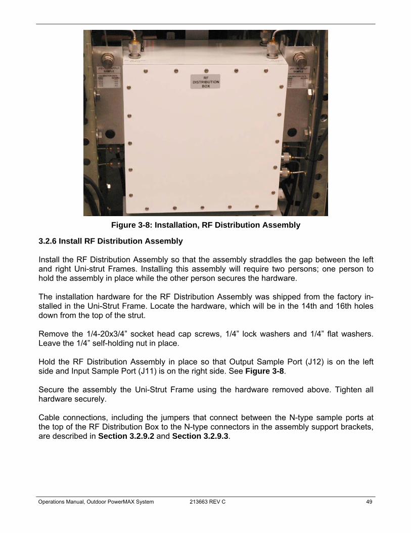
Operations Manual, Outdoor PowerMAX System 213663 REV C 49
3.2.6 Install RF Distribution Assembly Install the RF Distribution Assembly so that the assembly straddles the gap between the left and right Uni-strut Frames. Installing this assembly will require two persons; one person to hold the assembly in place while the other person secures the hardware. The installation hardware for the RF Distribution Assembly was shipped from the factory in-stalled in the Uni-Strut Frame. Locate the hardware, which will be in the 14th and 16th holes down from the top of the strut. Remove the 1/4-20x3/4” socket head cap screws, 1/4” lock washers and 1/4” flat washers. Leave the 1/4” self-holding nut in place. Hold the RF Distribution Assembly in place so that Output Sample Port (J12) is on the left side and Input Sample Port (J11) is on the right side. See Figure 3-8. Secure the assembly the Uni-Strut Frame using the hardware removed above. Tighten all hardware securely. Cable connections, including the jumpers that connect between the N-type sample ports at the top of the RF Distribution Box to the N-type connectors in the assembly support brackets, are described in Section 3.2.9.2 and Section 3.2.9.3.
Figure 3-8: Installation, RF Distribution Assembly

50 213663 REV C Operations Manual, Outdoor PowerMAX System
3.2.7 Install Optional AC Distribution Assembly For systems using the optional AC Distribution Box, install the AC Distribution Assembly so that the assembly straddles the gap between the left and right Uni-strut Frames. Installing this assembly will require two persons; one person to hold the assembly in place while the other person secures the hardware. The installation hardware for the AC Distribution Assembly was shipped from the factory in-stalled in the Uni-Strut Frame. Locate the hardware, which will be in the 25th and 28th holes down from the top of the strut. Remove the 1/4-20x3/4” socket head cap screws, 1/4” lock washers and 1/4” flat washers. Leave the 1/4” self-holding nut in place. Hold the AC Distribution Assembly in place so that door hinges are on the left side (when fac-ing the door) and the keyed locking mechanisms are on the right side. The mounting hard-ware will be attached at the back side of the assembly supports. See Figure 3-9. Secure the assembly the Uni-Strut Frame using the hardware removed above. Tighten all hardware securely. Open the front door and make sure all circuit breakers are switched off. Make sure all power cables at the rear of the assembly are free from tangles and snags. Cable connections will be described in Section 3.2.8.11.
Figure 3-9: Installation, AC Distribution Assembly
1/4-20 X 0.75” S.H.C.S., LOCK WASHERS &
FLAT WASHERS (4X)

Operations Manual, Outdoor PowerMAX System 213663 REV C 51
3.2.8 Install High Power Outdoor SSPAs Each Uni-Strut Frame has slots to install up to four (4) High Power Outdoor SSPAs.
Caution! Each SSPA weighs in excess of 100 lbs. (45.5 kg). At least two per-sons are required to install each SSPA. Lift the SSPA by the handles on either side. Do not lift from the RF Output waveguide flange or by the connectors.
Note: Follow the best practice of installing the bottom amplifiers first.
During factory test and set-up the system was optimized for best performance. It is therefore important to install each amplifier into the proper space. Match the amplifier label to the label affixed to the Uni-Strut Frame, and install that amplifier into that slot. The amplifiers should be slid along the uni-strut rails at the opening opposite the waveguide array. The amplifier should be positioned so the RF Output flange is inserted into the opening, with the SSPA supports at the bottom. See Figure 3-10. Carefully slide the amplifier along the uni-strut rail until the support hits the square washer stop. Adjust the amplifier side-to-side until the RF Output waveguide flange aligns with the waveguide array.
Note: Ensure there is a gasket between the waveguide flanges. Either full or half gaskets were shipped with the system, depending on the waveguide config-uration.
Secure the amplifier to the uni-strut rail using four (4) sets of 3/4” hex bolts, 3/4” lock washers, 3/4” flat washers and self-holding nuts, two per side, as shown in Figure 3-10. Secure the waveguide flanges together using the hardware provided.
Figure 3-10: Installation, High Power Outdoor SSPAs
1/2-13 X 1.25” HEX BOLT, 1/2” LOCK WASHER,
1/2” FLAT WASHER (4X)
SQUARE WASHER
STOP

52 213663 REV C Operations Manual, Outdoor PowerMAX System
3.2.9 Cable Connections This section describes the various cable connections that need to be made to complete the system installation. The cable part numbers are provided on the schematic shipped with the system. 3.2.9.1 System RF Input to RF Distribution Box This semi-rigid coaxial cable is used In systems that utilize a 1:1 Redundant vBUC System for L-Band to RF conversion. It is a pre-formed cable that should not be bent or otherwise re-shaped. At each cable end is a Type N (M) connector.
• Connect the cable labeled W11 between the RF output of the vBUC system and Port J9 of the RF Distribution Box.
If the redundant vBUC system is not used in the system, a customer-supplied cable with a Type N (M) connector should be attached directly to Port J9 of the RF Distribution Box. 3.2.9.2 RF Coaxial Cable from RF Distribution Box to SSPAs These semi-rigid coaxial cables are used to provide the RF signal to each of the system am-plifiers. They are pre-formed cables that should not be bent or otherwise re-shaped.
Important! Make sure the amplifiers are in the proper position, and that each coaxial cable is attached to the correct amplifier. Verify the cable identification on the schematic shipped with the system.
• Connect the cable labeled W1 between Port J1 of the RF Distribution Box and
Port J1 of SSPA 1.1. • Connect the cable labeled W2 between Port J2 of the RF Distribution Box and
Port J1 of SSPA 1.2. • Connect the cable labeled W3 between Port J3 of the RF Distribution Box and
Port J1 of SSPA 1.3. • Connect the cable labeled W4 between Port J4 of the RF Distribution Box and
Port J1 of SSPA 1.4. • Connect the cable labeled W5 between Port J5 of the RF Distribution Box and
Port J1 of SSPA 2.1. • Connect the cable labeled W6 between Port J6 of the RF Distribution Box and
Port J1 of SSPA 2.2. • Connect the cable labeled W7 between Port J7 of the RF Distribution Box and
Port J1 of SSPA 2.3. • Connect the cable labeled W8 between Port J8 of the RF Distribution Box and
Port J1 of SSPA 2.4. • Connect the cable labeled W9 between Port J14 of the RF Distribution Box and
the Crossguide Coupler Return Port (near the system RF Output flange). • Connect the cable labeled W10 between Port J1 of the RF Distribution Box and
the Crossguide Coupler Forward Port (near the system RF Output flange).

Operations Manual, Outdoor PowerMAX System 213663 REV C 53
3.2.9.3 RF Coaxial Cable between RF Distribution Box and Sample Ports These short semi-rigid coaxial cables connect between the RF Distribution Box and the sam-ple ports in the support brackets. They are pre-formed cables that should not be re-shaped.
• Connect the cable labeled W20 between Port J11 of RF Distribution Box and the Input Sample in the support bracket
• Connect the cable labeled W21 between Port J12 of RF Distribution Box and the Output Sample in the support bracket
3.2.9.4 Link Cable (L213828-1) The Link Cable connects the system’s SSPA Controllers and the RF Detector module housed within the RF Distribution Box. This cable is used to pass online/standby status information between the amplifiers. A label is affixed near each connector that describes the port to which it should be attached. An outline drawing of the Link Cable is shown in Figure 3-11.
3.2.9.5 Switch Cable (L213829-1) The Switch Cable connects to the system’s SSPA Controllers and the system switches. This cable allows the SSPA Controllers to monitor and control the switch position. A label is affixed near each connector that describes the port to which it should be attached. An outline draw-ing of the Switch Cable is shown in Figure 3-12.
Figure 3-11: Link Cable (L213828-1)
Figure 3-12: Switch Cable (L213829-1)

54 213663 REV C Operations Manual, Outdoor PowerMAX System
3.2.9.6 Auxiliary Power Cable (L213830-1) The Auxiliary Power Cable connects between Port J6 of each system SSPA Controller, Port J16 of the RF Distribution Box, and (when used) the Ethernet Hub power connector. This ca-ble provides power to the RF Detector Module housed within the RF Distribution Box (Port J16), and to the optional Ethernet Hub. A label is affixed near each connector that describes the port to which it should be attached. An outline drawing of the Auxiliary Power Cable is shown in Figure 3-13.
Figure 3-13: Auxiliary Power Cable (L213830-1)

Operations Manual, Outdoor PowerMAX System 213663 REV C 55
3.2.9.7 Controller DC In Power Cables (L213826-1, -2) Power to the SSPA Controllers is provided from each of the amplifiers in the array that the controller monitors and controls. The Controller Power Cables connect between Port J5 ofthe controller and Ports J6 and J8 of each amplifier in its array. A label is affixed near each con-nector that describes the port to which it should be attached. The –1 and –2 versions are identical other than the label identification. An outline drawing of a typical Controller Power Cable is shown in Figure 3-14.
Figure 3-14: Controller DC In Power Cables (L213826-1, -2)

56 213663 REV C Operations Manual, Outdoor PowerMAX System
3.2.9.8 Monitor & Control Cables (L213827-6, -7) Communication for monitor and control purposes between the SSPA Controller and each of the connected amplifiers is established through the Monitor & Control Cables. These cables connect to Port J4 of the SSPA Controller, and to Port J4 of each SSPA in the controller’s ar-ray of amplifiers. A label is affixed near each connector that describes the port to which it should be attached. The –6 and –7 versions are identical other than the label identification. An outline drawing of a typical Monitor & Control Cable is shown in Figure 3-15.
Figure 3-15: Monitor & Control Cables (L213827-6, -7)

Operations Manual, Outdoor PowerMAX System 213663 REV C 57
3.2.9.9 Controller Ethernet Cables (L213824-1) Connect each controller to the Ethernet Hub using the L213824-1 cables. A label is affixed near each connector that describes the port to which it should be attached. See Figure 3-16.
Connect the cable for Controller 1 between Port J9 of the controller, and Port 4 of the Ether-net Hub. Connect the cable for Controller 2 between Port J9 of the controller, and Port 5 of the Ethernet Hub. 3.2.9.10 Optional vBUC Ethernet Cables (L213825-1) For systems using the Redundant vBUC Plate Assembly, connect each vBUC converter to the Ethernet Hub using the L213825-1 cables. A label is affixed near each connector that de-scribes the port to which it should be attached. See Figure 3-17.
Connect the cable for vBUC1 between Port J4 of the vBUC and Port 2 of the Ethernet Hub. Connect the cable for vBUC2 between Port J4 of the vBUC and Port 3 of the Ethernet Hub. 3.2.9.11 SSPA Power Cables If the system is ordered with the optional AC Distribution Box, the power cables for the ampli-fiers are connected to that assembly. A label is affixed near each connector that describes the port to which it should be attached. Each power cable should be plugged in to the AC IN (J7) connector on the appropriate amplifier. See Section 2.1.2.7 for a description of SSPA Port J7. If the system is ordered with the optional Redundant vBUC Plate, the power cables for the vBUC converters are also connected to the AC Distribution Box. A label is affixed near each connector that describes the port to which it should be attached. Each power cable should be plugged in to the AC IN connector on the appropriate vBUC converter. See Section 2.6.2.4.1 for a description of vBUC converter AC IN connector.
Figure 3-16: Controller Ethernet Cables (L213824-1)
Figure 3-17: vBUC Ethernet Cables (L213825-1)

58 213663 REV C Operations Manual, Outdoor PowerMAX System
3.2.10 System RF Output Flange Remove the cover from the system RF Output Flange and connect to the waveguide feed to the antenna. Secure the waveguide flanges with the hardware provided. 3.2.11 System Prime Power Cable access ports with strain relief are available t the rear of the AC Distribution Box. A sep-arate access port for the return is also available. Use these access ports to introduce prime power cables to the terminal blocks on the inside of the AC Distribution Box. There is a removable panel inside the box that gives access to the terminal blocks. The wiring from the terminal block to the individual circuit breakers was assembled at the factory. See Figure 3-19 and Figure 3-20. Review the system schematic for proper wiring details. Switch on all circuit breakers to power up the system.
Figure 3-18: System RF Output Flange
Figure 3-19: Prime Power Cable Access
Figure 3-20: Terminal Block Access

Operations Manual, Outdoor PowerMAX System 213663 REV C 59
Section 4: Local Operation
4.0 Outdoor Controller Menu Structure Figure 4-1 shows the Outdoor Controller Menu Structure hierarchy. There are six main levels of menu selections.
1. Sys.Info - System Information menu sublevel (See Section 4.0.1) 2. Com.Setup - Serial Communication related settings (See Section 4.0.2) 3. Operation Setup - System operation related settings (See Section 4.0.3) 4. Fault Monitoring Setup - Fault handling settings (See Section 4.0.4) 5. Options - Backup/restore and password settings (See Section 4.0.5) 6. Redundancy - Switching and standby settings (See Section 4.0.6)
The menu tree is accessed by pressing the Main Menu key on the access panel of the out-door controller. Navigation through the menu structure is handled by using the Up Arrow [▲], Down Arrow [▼], Left Arrow [◄], and Right Arrow [►] keys and the Enter key to select from the items shown in the controller display. For menus where an actual numerical value must be entered, the Up Arrow [▲] and Down Arrow [▼] keys change the number by factors of 10; the Left Arrow [◄] and Right Arrow [►] keys change the number in increments of 1.
Note: If the Local/Remote key is toggled so that the Remote LED is illuminat-ed, the Main Menu key, Arrow keys and Enter key are disabled. To regain local control, press the Local/Remote key so that the Local LED is illuminated.
Figure 4-1: Front Panel Menu Structure
2.Com Setup1.Sys Info 3.Operation 4.Flt. Setup 5.Options
Main Menu
6.Redundancy
To Sys Info Page 1

60 213663 REV C Operations Manual, Outdoor PowerMAX System
4.0.1 System Information Sub-Menu The informative sublevel menu structure contains several pages, shown in Figure 2-5.
IP Setup Menus
IPAddr:XXX.XXX.XXX.XXX MAC:XXXXXXXXXXSubnet:XXX.XXX.XXX.XXX Port:XXXXX
Gateway:XXX.XXX.XXX.XXXLockIP:XXX.XXX.XXX.XXX
CommunityGet:XXXXXXXXXXXXXXXXXXXXXCommunitySet:XXXXXXXXXXXXXXXXXXXXX
1.IPInfo
SSPA Firmware Info
Teledyne Paradise Datacom LLCDigicore X Version X.XX (XX) Built YYYY.MM.DD
SSPAID:XXXXXXXXXXXXXXXXXXXXUserInfo:XXXXXXXXXXXXXXXXXXXX
Firmware:XXXXXXXXXX Module1ID:XXXXXXXXXXXXXXXXXXXXXX
1.Info
Firmware:XXXXXXXXXX Module2ID:XXXXXXXXXXXXXXXXXXXXXX
Firmware:XXXXXXXXXX Module3ID:XXXXXXXXXXXXXXXXXXXXXX
Firmware:XXXXXXXXXX Module4ID:XXXXXXXXXXXXXXXXXXXXXX
MainMenu 3.Operation
MainMenu 2.Com Setup 5.IPSetup
Web Password:XXXXXXXXXXXXXXXXXXXXXTrapNMSIP: XXX.XXX.XXX.XXX
N+1 Slave UnitUnit operation under system control
N+1 Slave unit system info
Slave UnitsMaster Unit only
PS:XXXXXX LowRF:XXXXXX Fan:XXXXXXAUX:XXXXXX VSWR:XXXXXX BUC:XXXXXX
RFSW1:XXXXXX State:XXXXXX Prior:XXXXRFSW2:XXXXXX Mute:XXXXXX PolSel:XXXX
Prtcl:XXXXXX Intrfc:XXXXX Buzzer:XXXBaud:XXXXX Addrs.:XXX Latch:XXX
Mode:XXXXXXX Ctrl:XXXXXX Unit:XXXXStby:XXXX Switch:XXXXX FSpeed:XXX
PS1(V):XX.X Boost1(V):XX.X DC(A):XX.XPS2(V):XX.X Boost2(V):XX.X
Regulator:XXXXXX Temperature:XXXXXXDCCurrent:XXXXXX Temp.(C):XXX
Mod1:XXXXX Mod3:XXXXX PreAmp:XXXXXMod2:XXXXX Mod4:XXXXX PSModFlts:XXX
Atten.(dB):XX.X FrwrdRF(dBm):XX.XAlarms:XXXXXX Ref.RF(dBm):XX.X
System Info Menus
1.Sys.Info
MainMenu
Non N+1 Units
Atten.(dB):XX.X SysRFOut(dBm):XX.XAutoGain(dB):XX.X Ref.RF(dBm):XX.X
N+1 Arr.Size:XXX N+1 Alarms:XXXXXXN+1 Address:XXX N+1 State:XXXXXX
N+1 Master unit system info
Cabinet Temp(C):XXX N+1Stbys::XXXXXXCabinet Fan:XXXXXX
Firmware:XXXXXXXXXX PreAmpID:XXXXXXXXXXXXXXXXXXXXXXChssy Temp(C):XXX BUC PS1(V): XX.X
RecordHigh(C):XXX BUC PS2(V): XX.X
MuteFault:XXXXX LastFault:XXXXXMFaultCause:XXXXX MasterN1IP:XXX
PSType:XXX DigicoreID:XXX I/OBoardID:XXX
Current Date/Time:YY/MM/DD HH:MM:SS
HPA Run Time: Days:DDDD Hrs:HH Min:MM Sec:SS
1.Clear Faults2.Back
Enter
1.Clear Faults2.Back
Enter
Enter
Figure 4-2: System Information Sub-Menu

Operations Manual, Outdoor PowerMAX System 213663 REV C 61
The user can also browse among these pages by navigating the cursor around the menu fields and pressing the Enter button on the keypad. Note that this function will not work if the “Fault Latch” option is selected. In a N+1 configuration, the Master unit default System Information page is as described in Section 4.0.1.21; the default page for Slave units is as described in Section 4.0.1.22. In non-N+1 configurations, the default page is as described in Section 4.0.1.1. 4.0.1.1 Sys Info Page 1 This is the HPA main status information page. The page shows:
• Atten.(dB) — HPA attenuation measured in dB, with accuracy of 0.1 dB; • FrwrdRF(###) — Forward RF Power, measured in either dBm with resolution of
0.1 dBm, or Watts with a resolution of 0.1 Watts, with a 20 dBm dynamic range from the maximum rated output power;
• Alarms — Will display “FAULT!” if a fault is present on the HPA, or “None” if no fault is present.
• Ref.RF(###) — Reflected RF Power, measured in either dB with resolution of 0.1 dBm, or Watts with a resolution of 0.1 Watts. Displays “N/A” if unavailable. See Section 4.5 for further discussion.
When on this page, pressing the Enter key will open the Clear Faults Menu. The Clear Faults Menu is also available from the N+1 Master Page 1 and N+1 Slave Info Page. 4.0.1.1.1 Clear Faults Menu This page allows user to clear latched faults conditions, if the Fault Latch option is enabled.
• 1.Clear Faults — When selected, all latched fault conditions are cleared. Also Master N+1 unit fault history and SNMP trap history will be cleared when “Clear Faults” function is selected.
• 2.Back — When selected, navigates back to System Info page without clearing fault state holders.
4.0.1.2 Sys Info Page 2 This page shows a variety of alarm states which may be present within the HPA. Fault values could be “FAULT!”, “Normal” and “N/A”. If the fault condition doesn't apply to the HPA it will display “N/A” for “Not Available”.
• PS — Power supply alarm, displays “Normal” if HPA power supplies are normal-ly operational and “FAULT!” if one or more power supplies failed.
• LowRF — Low RF fault; • Fan — Cooling system failures; • Aux. — Auxiliary fault condition; • VSWR — High Reflected power fault; • BUC — Block Up converter fault.

62 213663 REV C Operations Manual, Outdoor PowerMAX System
4.0.1.3 Sys Info Page 3 This page displays miscellaneous information related to the redundancy operation and the HPA mute status.
• RFSW1 — Displays the state of RF switch 1, possible values - “Pos1”, “Pos2”, “N/A”, “FAULT!”;
• RFSW2 — Displays the state of RF switch 2, possible values - “Pos1”, “Pos2”, “N/A”, “FAULT!”;
• State — HPA online state, possible values “Online”, “Standby”; • Mute — HPA mute state, possible values “Clear”, “Set”; • Prior — Priority polarization select (1:2 Mode Only); • PolSel — Current Polarization output (1:2 Mode Only)
4.0.1.4 Sys Info Page 4 This page displays various HPA settings:
• Prtcl. — Current HPA remote control protocol. Will display “Terminal”, if terminal mode protocol is currently active and “Normal” if string I/O type protocol is used.
• Baud — Selected baud rate for remote control serial port. Selection: “2400”, “4800”, “9600”, “19200”, “38400”;
• Intrfc. — Selected serial port interface. Selection: “RS232”, “RS485”. • Addrs. — HPA remote control network address. Value could be in range from 0
to 254. Note: address 255 is reserved for global calls and should not be used for an individual unit’s addressing.
• Buzzer — Audible alarm availability. “Dis” for disabled or “Enb” for enabled. • Latch — Fault latch option selection. “Dis” for disabled or “Enb” for enabled.
4.0.1.5 Sys Info Page 5 Page 5 shows settings related to the HPA 1:1 Redundant System operation.
• Mode — Indicates HPA operational mode. See Section 4.0.3.4. • Stby. — Shows the HPA standby state selection. “Hot” - Hot standby operation
(HPA retains unmuted state during standby); “Cold” - Cold standby (HPA always mutes itself in standby mode and unmutes when switched online).
• Ctrl. — Shows HPA control style. “Local” - Both local and remote control are supported; “Remote” - When only remote control provided (keypad locked);
• Switch — Indicates switching style. “Auto” - Automatic fault tracking/switching; “Manual” - If redundancy switching is provided by the operator.
• Unit — Redundancy topological factor. “HPA1” - HPA connected to RF switch port 1 or 4 (Online Position 1 of the RF switch); “HPA2” - HPA connected to RF switch port 2 or 3 (Online Position 2 of the RF switch).
• FSpeed — Displays the current fan speed setting of “Hi”, “Low” or “Auto”.

Operations Manual, Outdoor PowerMAX System 213663 REV C 63
4.0.1.6 Sys Info Page 6 This page shows the status of the HPA’s internal power supplies.
• PS1(V) — Main power supply 1 output voltage with resolution of 0.1V. Normal output voltage for GaAs amplifiers is in the range of 11 to 13 V; Normal output voltage for GaN amplifiers is in the range of 25 to 28 V.
• PS2(V) — Main power supply 2 output voltage. • Boost1(V) — Booster power supply 1 output voltage with resolution of 0.1V.
Normal range 24 to 30 V (typical 28V); • Boost2(V) — Booster power supply 2 output voltage. • DC (A) — Total DC current draw by RF modules from main power supply. Value
varies depending on the power level of the HPA. If the HPA is muted, current normally drops to within the 0 to 5 A range.
4.0.1.7 Sys Info Page 7 This page shows RF module related faults and conditions.
• Regulator — RF module regulator low voltage fault. Values: “FAULT!” or “Normal”;
• DC Current — Low DC current fault. Values: “FAULT!” or “Normal”; • Temperature — High temperature fault. Values: “FAULT!” or “Normal”. • Temp.(C) — Internal RF module plate temperature in Celsius. In multi-module
units, only the hottest module baseplate temperature is displayed. 4.0.1.8 Sys Info Page 8 This page shows individual RF module states in multi-module HPAs.
• Mod# & PreAmp — Mod1 to Mod4 represent the overall state of the relevant RF Power modules. If the amplifier is equipped with a separate pre-amplifier module, the “PreAmp” value will represent the overall state of the pre-amplifier. Under normal operation, the value will read “Normal”. If a unique module does not exist in the HPA configuration, the value shows “N/A” (not available). Each value represents the summary fault state of an indi-vidual RF module, which includes the Voltage, Current and Temperature state as well as the quality of data connection with module. For a module or pre-amp exhibiting a fault condition, the value will read “FAULT!”. If the HPA controller card cannot reliably communicate with an SSPA module, that module will be declared faulted. This type of fault will not affect the overall summary fault state, because the controller card has the ability to track RF mod-ule faults independently. When an existing module or pre-amp is present in the current HPA configuration, but fails to respond to control board status queries, “ComErr” (Communication Error) will be displayed.

64 213663 REV C Operations Manual, Outdoor PowerMAX System
• PSModFlts — For amplifiers utilizing an external N+1 power supply, this value indicates the number of detected N+1 PS module faults. For units with an inter-nal power supply, this value reads “000” and should be ignored. Check PS1 and PS2 Voltage readings to assess the state of an internal power supply.
4.0.1.9 Sys Info Page 9 (version 6.00) This page shows various miscellaneous operation parameters.
• Chssy Temp — Chassis temperature reading measured by the control board. Since the control board is typically located at rear of the chassis, this reading correlates with the exhaust air temperature;
• RecordHigh — The highest temperature detected over unit lifetime. This value is updated each time a temperature higher than the current record is detected. Value could be used for SSPAs problem troubleshooting. Record data is factory reset only.
• BUC PS1(V) — This value represents the power supply voltage used for biasing an optional BUC unit. Voltage could be used for detecting problems related to BUC operation. The SSPA does not have a specific alarm threshold for this volt-age. Normal reading for this parameter should be in range of 15V– 16V.
• BUC PS2(V) — This value represents secondary BUC power supply voltages. For a unit equipped with a single power supply this value shows “N/A” (not avail-able).
4.0.1.10 Sys Info Page 10 (version 6.00) The page shows advanced fault analysis information and advanced N+1 operation features.
• MuteFault – This parameter allows the user to check the SSPA mute condition. Possible values: ○ Clear — No present fault mute condition on SSPA unit. Mute/Unmute func-
tion under full user control; ○ Set — One or more mute fault conditions present in the system. The unit is
forced to the Mute On condition. • MFltCause — Parameter allows user to determine last detected Mute fault con-
dition. Possible values: ○ None — No detected Mute fault conditions; ○ AuxFlt — Mute fault condition triggered by a detected Auxiliary fault. ○ ExtM — Mute condition forced by external signal applied on the parallel port
Mute input; ○ BUCFlt — Mute fault condition caused by a detected BUC fault; ○ PSFlt — The unit is forced to mute due to one or more failed N+1 power
supply modules; ○ N+1Flt — N+1 configuration forced unit into a mute state due to an internal
summary fault condition; • LastFault – This parameter shows information about the last detected fault. The
value is latched to the last fault occurrence. Use the Clear Fault function to re-set. Possible Values: ○ LowRF – Low RF level fault;

Operations Manual, Outdoor PowerMAX System 213663 REV C 65
○ AuxFlt – Auxiliary fault; ○ BUCFlt – Block Up converter fault; ○ PSFlt- Power Supply fault; ○ ColdSt – Unit cold start power up detected; ○ N+1Flt – N+1 System Fault; ○ TmpFlt – High temperature fault; ○ RegFlt – Voltage Regulator fault; ○ CurFlt – Low DC Current fault; ○ HiVSWR – High reflected RF level fault; ○ Other – Unknown fault condition; ○ None – No information about present or past fault conditions (Clear Fault
function was implemented by user); 4.0.1.11 IP Info Page 1 This page is available through the Comm. Setup menu, and shows SSPA settings related to the IP interface.
• IP Address – IP address of the SSPA. Consult your network administrator to set this address according to your LAN configuration.
• MAC – Medium Access Control address of the SSPA Ethernet controller. This address is factory preset.
• Subnet – IP subnet mask of the SSPA. Consult your network administrator to set this address.
• IPPort – IP port value for the SSPA. This address is valid only when IPNet pro-tocol is selected. The port value should not be selected outside the existing ser-vices range to avoid access conflict on the M&C PC end.
4.0.1.12 IP Info Page 2 This page shows SSPA settings related to the IP interface.
• Gateway – IP Gateway address. This address is used only if access to the SSPA is provided from an outside LAN. If no such access is required, the ad-dress must be set to 0.0.0.0
• LockIP – This address is used to increase the security measure for the IPNet protocol. The SSPA will answer a request which comes only from a specified IP address. Set this address value to 255.255.255.255 to disable this feature. See Section 4.0.2.5.1.
4.0.1.13 IP Info Page 3 This page shows SSPA settings related to the IP interface.
• CommunityGet – Security string used in SNMP protocol for “Get” requests. Set this value to match the value specified in the NMS or MIB browser. Maximum string length is 20 alpha-numeric characters. The string allows read operation for the RM SSPA SNMP agent.

66 213663 REV C Operations Manual, Outdoor PowerMAX System
• CommunitySet – Security string used in SNMP protocol for “Set” requests. Set this value to match the value specified in the NMS or MIB browser. For security reasons this string must be different than the Community Get string. The maxi-mum string length is 20 alpha-numeric characters. The string allows write opera-tion for the RM SSPA SNMP agent.
Note: Community strings are essentially passwords. The user should use the same rules for selecting them as for any other passwords: no dictionary words, spouse names, etc. An alphanumeric string with mixed upper- and lower-case letters is generally a good idea.
4.0.1.14 IP Info Page 4 This page contains information about the web password and Trap NMSIP.
• WebPassword — Indicates the selected password for the web page interface. A blank value indicates that the web interface does not require a password pro-tected login.
• TrapNMSIP — Shows the selected IP address for the SNMP trap recipient. (Version 6.00).
4.0.1.15 Firmware Info Page 1 This page is available through the Operation Setup menu, and provides information about the SSPA micro-controller unit firmware revision level and build date. 4.0.1.16 Firmware Info Page 2 (version 4.0) This page provides additional SSPA information.
• SSPA ID – SSPA unique serial and model number. • UserInfo – User information string, which could be set over SNMP protocol (see
SNMP MIB info for details) 4.0.1.17 Firmware Info Pages 3, 4, 5 and 6 (version 4.0) These pages contain information about the firmware revision level and unique ID of each RF module. A unit may contain one to four RF modules. Pages will remain blank if a particular module is not installed. 4.0.1.18 Hardware Info Page 8 (version 6.00) This page shows the hardware ID markers for the power supply configuration, the type of hardware build of the DigitalCore board and the I/O board. This information is for factory use only.

Operations Manual, Outdoor PowerMAX System 213663 REV C 67
4.0.1.19 HPA Local Time Page 9 (version 6.00) This page shows the optional device clock. The device clock is a user selectable parameter. User set time is power dependent. A backup capacitor is used to keep the clock running while the SSPA is powered down. The clock will need to be reset if the unit remains without power longer than 5 hours. Clock output format is Year/Month/Day Hours:Minutes:Seconds. Only 24-Hour format is sup-ported at this time. 4.0.1.20 HPA Run Time Page 10 (version 6.00) This page shows the days, hours, minutes and seconds since the unit was last powered up. 4.0.1.21 N+1 Master Info Page 1 This page can only be viewed when the SSPA unit is configured as the N+1 Master unit. The page also becomes the default startup page for the Master SSPA . Several parameters related to N+1 System operational parameters are displayed:
• Atten.(dB) — System level attenuation. In the case when the N+1 Auto Gain option is turned on, this attenuation level may differ from an individual SSPA at-tenuation level;
• AutoGain(dB) or SSPAGain(dB) — Displays the estimated system wide linear gain. Actual SSPA gain may differ if the unit has reached its saturated power level or malfunctions (see Section 4.0.6.6.3);
• SysRFOut — Indicates system forward RF output power detected at the output flange of the final phase combined structure. This value can be displayed in dBm or Watts, depending on the RF Unit setting. If the RF power detector unit is not accessible for any reason, the value shown will be “N/A”.
Note: If detected power falls below lowest detectable threshold it will read 0.00. In reality, RF output power may differ from the displayed value. Consult the system datasheet on RF detector dynamic range specifications.
• Ref.RF — Indicates system reflected RF power. This value can be displayed in
dBm or Watts, depending on the RF Unit setting. If the RF power detector unit is not accessible for any reason, the value shown will be “N/A”.
Note: If reflected power falls below lowest detectable threshold it will read 0.00. In reality, RF output power may differ from the displayed value. Consult the system datasheet on RF detector dynamic range specifications.
When on this page, pressing the Enter key twice will open the Clear Faults Menu. The Clear Faults Menu is also available from Sys Info Page 1 and N+1 Slave Info Page.

68 213663 REV C Operations Manual, Outdoor PowerMAX System
4.0.1.21.1 Clear Faults Menu This page allows user to clear latched faults conditions, if the Fault Latch option is enabled.
• 1.Clear Faults — When selected, all latched fault conditions are cleared. Also Master N+1 unit fault history and SNMP trap history will be cleared when “Clear Faults” function is selected.
• 2.Back — When selected, navigates back to System Info page without clearing fault state holders.
4.0.1.22 N+1 Slave Info Page Figure 4-3 shows the display for all Slave units in the system.
This page can only be viewed when a unit is assigned as a N+1 Slave unit. All normal Info pages pertaining to individual SSPA operation parameters are accessible on subsequent menu levels. This page becomes the default page for a N+1 slave unit. When on this page, pressing the Enter key will open the Clear Faults Menu. The Clear Faults Menu is also available from Sys Info Page 1 and N+1 Master Page 1. 4.0.1.22.1 Clear Faults Menu This page allows user to clear latched faults conditions, if the Fault Latch option is enabled.
• 1.Clear Faults — When selected, all latched fault conditions are cleared. Also Master N+1 unit fault history and SNMP trap history will be cleared when “Clear Faults” function is selected.
• 2.Back — When selected, navigates back to System Info page without clearing fault state holders.
4.0.1.23 N+1 Master Info Page 2 This page displays additional N+1 system operation data, and can be accessed by pressing the Up Arrow (▲) key from the N+1 Master Info Page 1. This page is only accessible from the N+1 Master unit.
• N+1 Arr.Size — Displays the N+1 array size. Valid sizes: 2, 4, 8 or 16 units. • N+1 Address — Displays the master unit N+1 priority address; • N+1 Alarms — Displays the number of detected SSPA unit alarms present in
the system. • N+1 State — Displays the current N+1 fault state. If the Master unit detects no
more than one (1) SSPA chassis alarm, the N+1 state will be displayed as “Normal”; otherwise “FAULT!”.
Figure 4-3: Slave Unit Display

Operations Manual, Outdoor PowerMAX System 213663 REV C 69
4.0.1.24 N+1 Master Info Page 3 This page displays information related to N+1 system operation, and can be accessed by pressing the Up Arrow (▲) key twice from the N+1 Master Info Page 1. This page is only ac-cessible from the N+1 Master unit.
• Cabinet Temp(C) — Not applicable in the Outdoor PowerMAX system. • Cabinet Fan — Not applicable in the Outdoor PowerMAX system.
4.0.2 Communication Setup Sub-Menu This menu, shown in Figure 4-4, allows the user to select the parameters for communication between the SSPA and any remote monitor and control station. 4.0.2.1 Protocol Allows the user to select the serial protocol. Available communication protocols include:
• Normal — As described in Section 8. • Terminal — As described in Section 8.5.
2.Com Setup
3.SysAddress
1.2400
1.RS232
3.Subnet
1.Community Get
1.Sys Info
2.Baud Rate
2.Terminal 1 .. 255
2.LocalIP
3.Operation
4.Interface
2.4800
2.RS485
4.Gateway
2.Community Set
4.Flt. Setup
5.IP Setup
3.9600
3.IPNet
5.LocalPort
3.Lock IP
5.Options
4.19200
4.SNMP
6.More
1.Protocol
1.Normal
5.38400
1.IPInfo
Main Menu
6.Redundancy
To IP Info Page
4.Web Password
6.N+1Cntrl
3.SerAddrs2.MasterIP Dis 4.IPAddrs 5.Info 6.Back1.MasterIP Enb
5.More 6.Back
1.SetTrap 2.CondTrap 3.TimeSet 4.TrapNMSIP 5.Back
Figure 4-4: Communication Setup Sub-Menu

70 213663 REV C Operations Manual, Outdoor PowerMAX System
4.0.2.2 Baud Rate Selects the desired baud rate for serial communication. Available baud rates include 2400, 4800, 9600, 19200 and 38400. The factory default Baud Rate is 9600. 4.0.2.3 System Address Sets the network address of the controller if used on a RS-485 network. Choose 1-255. The factory default address is 0.
Note: Changes in serial communication settings from the controller’s front panel are effective immediately. Changes to these parameters from serial interface require that the unit be reset in order to take effect. The units can be reset either by cycling power or by issuing a reset command from the controller front panel. See Section 4.0.5.6.
4.0.2.4 Interface User may selected between RS232, RS485, IPNet (Ethernet) or SNMP communication. 4.0.2.5 IP Setup Select between the following menu items:
• 1.IP Info — This selection allows the user to review all IPNet Settings as de-scribed in Section 4.0.1.11 through Section 4.0.1.14)
• 2.Local IP — This selection allows the user to set the unit’s Local IP Address;
• 3.Subnet Mask — This selection allows the user to set the Subnet Mask;
• 4.Default Gateway — This selection allows the user to set the network Default
Gateway Address;
• 5.LocalPort — This selection allows the user to set the Local Port for the unit.
The default Local Port address is 1007;
• 6.More — This selection opens the menu items listed in Section 4.0.2.5.1.
NewIP:XXX.XXX.XXX.XXX
SubnetMask:XXX.XXX.XXX.XXX
DefGateway:XXX.XXX.XXX.XXX
LocalPort:XXXXX

Operations Manual, Outdoor PowerMAX System 213663 REV C 71
4.0.2.5.1 More (SNMP, IP and Web Settings) This menu allows the user to set the Community String Selection (Set/Get) and assign the Web Password. Use the Up Arrow [▲] and Down Arrow [▼] keys to browse through selected characters. Press the Up Arrow [▲] and Down Arrow [▼] keys simultaneously to erase the selected character. Press the Left Arrow [◄] and Right Arrow [►] keys to navigate within the string. Maximum length is 20 characters.
• 1.Community Get — This selection allows user to set the SNMP Community Get String. Default is “public”;
• 2.Community Set — This selection allows user to set the SNMP Community
Set String. Default is “private”;
• 3.LockIP — This selection allows user to set the IP address from which re-
quests will be accepted by the amplifier. The LockIP selection gives the user the ability to increase the security measure for the IPNet protocol. The SSPA will answer a request which comes only from the assigned IP address. For firmware prior to version 6.00, set this address value to 0.0.0.0 or 255.255.255.255 to dis-able this feature. Starting with version 6.00, the Lock IP address function has been updated to allow “Binding” and “Masking” functions. Binding" means that the first datagram retrieved for this socket will bind to the source IP address and port number. Once binding has been completed, the SSPA will answer to the bound IP source until the unit is restarted or reset. Without binding, the socket accepts datagrams from all source IP addresses. Address 0.0.0.0 allows all peers, but provides binding to first detected IP source; Address 255.255.255.255 accepts all peers, without binding. If Lock IP is a multicast address, then the amplifier will accept queries sent from any IP address of multicast group;
• 4.WebPassword — This selection allows the user to set the password for the
web interface. Default is “paradise”. Erase all characters to disable password protection;
• 5.More — This selection opens the menu items listed in Section 4.0.2.5.2. • 6.Back — This selection opens the menu items listed in Section 4.0.2.5.
CommunityGet:public
CommunitySet:private
LockIP:255.255.255.255
WebPassword:paradise

72 213663 REV C Operations Manual, Outdoor PowerMAX System
4.0.2.5.2 More (Traps and Time Settings) This menu allows the user to set SNMP Trap settings, and also set the internal clock.
• 1.SetTrap — This selection allows the user to set the Settings Trap;
• 2.CondTrap — This selection allows the user to set the Conditions Trap;
• 3.TimeSet — This selection allows the user to set the time. Clock output format
is YY/MM/DD HH:mm. Only 24-Hour format is supported at this time. Press the Up Arrow [▲] key to increment the value highlighted by the cursor. Press the Down Arrow [▼] key to decrease the value highlighted by the cursor. Press the Right Arrow [►] key to move the cursor to the right; Press the Left Arrow [◄] key to move the cursor to the left;
• 4.TrapNMSIP — This selection allows the user to set the Trap NMS IP Address;
• 5.Back — This selection opens the menu items listed in Section 4.0.2.5.1.
4.0.2.6 N+1 Control (Floating Master Mode) This menu allows the user to set parameters relating to Floating N+1 Master operation. This feature allows having a single point of control for an N+1 system Master Module. When enabled, this mode will switch the N+1 Master Module serial and IP address to a dedicated floating Master IP and serial address. Without this function, a faulted Master Module in an N+1 system delegates its control privileg-es to another unit, which has a different serial and IP address. With this feature activated, the Master serial and IP address are reassigned to the new Mas-ter Module and the former master unit restores its normal communication parameters. This mode of operation allows having single M&C connection point bonded to a known IP and Serial address, regardless which module in the N+1 system assumes the role of the Master Module. In this mode, the user could maintain a remote connection to a single Master unit. Simultaneous connections to other modules is optional. If Floating Master mode is disabled, the N+1 Master unit responds to its unique IP and serial address rather than to a dedicated master address. In this mode, simultaneous connection to all N+1 unit in the system is the most desirable method of remote control operation.
SettingsSend:XX
ConditionsSend:XX
Set New Time (YY/MM/DD HH:mm)YY/MM/DD HH:mm
TrapNMSIP:XXX.XXX.XXX.XXX

Operations Manual, Outdoor PowerMAX System 213663 REV C 73
Floating Master mode could be used over both RS-485 and IP network. Communication over a RS-485 network requires the assignment of a unique Master serial address. The module currently assigned as the Master Module will also respond to queries on its own serial ad-dress. When this mode is used over an IP network, certain factors need to be taken in account:
• The Master IP address must be a unique address, not used anywhere else on the network;
• Since Floating Master mode is assumed, the Master Module will stop respond-ing on its individual IP address and start responding on Master IP address. When the Master Module assumes slave mode (and another unit is assigned the Master privileges), the former Master unit responds to its individual IP ad-dress;
• The Master address should be selected from same subnet mask and use the same gateway address as the rest of the N+1 units in the system;
• During the switchover process from a unit’s normal IP address and Master ad-dress and back, the SSPA unit will execute a “gratuitous ARP” request to a net-work. The operator needs to make sure that the network equipment connected to the system supports dynamic ARP tables which could be updated by “gratuitous ARP”. Consult your network administrator for details;
• Floating Master mode needs to be disabled if network switches utilize static ARP tables or if dynamic IP changes are forbidden.
Use of a dedicated serial Master address is optional, but desirable. Menu selections include:
• 1.MasterIP Enable — This selection enables Floating Master Control mode; • 2.MasterIP Disable — This selection disables Floating Master Control mode; • 3.Serial Address — This selection allows the user to assign a unique floating
serial control address to the N+1 Master; • 4.IP Address — This selection allows the user to assign a unique floating IP
address to the N+1 Master; • 5.Info — This selection displays a informational menu regarding the Floating
N+1 Master mode. Includes the mode state (Enabled/Disabled), the assigned serial address and assigned IP address.
• 6.Back — This selection opens the menu items listed in Section 4.0.2.6.

74 213663 REV C Operations Manual, Outdoor PowerMAX System
4.0.3 Operation Setup Sub-Menu This menu, shown in Figure 4-5, allows the user to select system-specific options. 4.0.3.1 Info Shows the current firmware version. See Figure 4-2 and Section 4.0.1.12 through Section 4.0.1.15. 4.0.3.2 Buzzer Toggles the audible alarm buzzer on/off. Factory default is Enabled. 4.0.3.3 Mute Allows user to Set or Clear the Mute status for the unit. Muting the amplifier via remote M&C requires 70 msec maximum (30 msec typical). 4.0.3.4 Sys. Mode Selects the logical state machine used by the controller. Available choices are:
• Standalone – Select this option for standalone SSPA application. All RF wave-guide switch controls are disabled;
• 1:1 Redundancy – Select this option for classic internal 1:1 redundancy appli-cation. For proper function, a second SSPA is required and also needs to be configured for the same operation mode. Other settings may need to be select-ed, see internal 1:1 operation section for details;
• 1:2 Mode – This setting is used for the internal 1:2 redundancy operation sche-ma. See relevant section for operation details;
• PhComb – Mode used for hybrid 1:1 phase combined operation. Use of N+1 controls is recommended in conjunction with 1:1 phase combined operation. See 1:1 phase combined operation section for details;
Figure 4-5: Operation Setup Sub-Menu
2.Com Setup1.Sys Info
2.Buzzer
3.Operation 4.Flt. Setup 5.Options
1.Info
Main Menu
6.Redundancy
3.Mute 4.Sys.Mode 5.Attenuation 6.RF Units
1.StdAlone
0.0 .. 20.0 dB
2. 1:1 Mode1.Buzzer On 2.Buzzer Off
1.Mute On 2.Mute Off
3. 1:2 Mode
1.dBms 2. WattsTo SSPA Firmware Info Page
4.1:1 PhComb 5.1:2 PhComb 6.SinglSw

Operations Manual, Outdoor PowerMAX System 213663 REV C 75
• 1:2PhComb – This mode is similar to 1:2 mode, but is used to combine two SSPA outputs rather than supplying a signal for two separate polarizations. Use of N+1 controls in conjunction with 1:2 phase combined operation. See 1:2 Phase combined operation section for details.
• SinglSw – This SSPA mode allows the control of a maintenance switch con-nected to the output of single SSPA unit. This is not a redundancy operation mode. The switch is used to redirect the output of an SSPA between an anten-na and a dummy load. See Maintenance Switch Operation section for details.
4.0.3.5 Attenuation Allows user to set the desired attenuation between 0 and 20.0 dB in 0.1 dB steps. 4.0.3.6 RF Units Allows user to set the unit of power measurement between dBm or Watts.
4.0.4 Fault Monitoring Setup Sub-Menu This menu, shown in Figure 4-6, allows the user to select how the SSPA will deal with fault conditions. 4.0.4.1 BUC Fault Allows the user to select the Action and the Fault Logic for fault conditions associated with the BUC. User can select the following Actions: Fault + Mute; Fault; Alert; Ignore. User can select the following Fault Logic parameters: Fault on High; Fault on Low.
Figure 4-6: Fault Monitoring Setup Sub-Menu
2.Com Setup1.Sys Info 3.Operation 4.Flt. Setup 5.Options
1.BUC Fault
Main Menu
6.Redundancy
2. Aux. Faults 3. RFSw Faults 4.Fault Latch
1.Enable 2.Disable
5.Low RF / ALC
1.Fault 4.Ignore3.Switch Mute2.Alert
1.Fault (LowRF) 4.Ignore3.ALC On2.Alert
1.Action 2.Fault Logic
1.Fault 4.Ignore3.Fault+Mute2.Alert
1.Fault on High 2.Fault on Low
1.Action 2.Fault Logic
1.Fault 5.Ignore3.Fault+Mute2.Alert
1.Fault on High 2.Fault on Low
5.Set Level
1.RF Level
MENU ITEMNOT ACTIVE
UNDER N+1 OPERATION
4.Alert+Mute

76 213663 REV C Operations Manual, Outdoor PowerMAX System
4.0.4.2 Auxiliary Faults Allows the user to select the Action and the Fault Logic for fault conditions associated with the Auxiliary connections. User can select the following Actions: Fault; Alert; Fault + Mute; Alert + Mute; Ignore. User can select the following Fault Logic parameters: Fault on High; Fault on Low. See Section 2.1.2.7.1 for a description of how to mute the amplifier using the Alert + Mute option. 4.0.4.3 RF Switch Faults Determines whether a switch fault should cause a major alarm and attempt to switch, or simp-ly show an alert on the display menu, the latter case considered a minor alarm.
• 1.Fault — This is the Major Alarm mode. Summary alarm on fault; • 2.Alert — This is the Minor Alarm mode. No summary alarm on fault; • 3.Switch Mute — In this mode, when the switch position changes, the amplifier
is momentarily muted during switchover to prevent arcing in the waveguide; • 4.Ignore — This setting ignores any RF Switch faults.
4.0.4.4 Fault Latch Determines the alarm reporting condition. A latched alarm will remain indicated on the control-ler front panel until the operator clears the alarm by pressing the Enter key. Unlatched alarms will allow the summary alarm indicator to stop displaying the alarm condition if the circum-stance creating the alarm has been cleared or corrected. 4.0.4.5 Low RF / Automatic Level Control Alerts the user when the output power falls below the threshold value, which is adjustable by the user with 1 dBm steps by selecting the “Set Level” menu item. Fault handling is adjustable by user, who may choose between Alert Only (Minor Fault), Fault (Major Fault), and Ignore. In addition, the user may select Automatic Level Control from this menu.
1. Select 3.ALC On and press the Enter key; 2. Select 5.Level; 3. Use the arrow keys to set the desired output level and press the Enter key.
Once activated, the ALC will take control of the amplifier’s attenuation setting to maintain the desired RF output power level and will not allow any attenuation adjustments via the front panel. The ALC circuit will have the greatest ability to adjust for positive and negative RF in-put level changes when the amplifier’s gain level is typically 65 dB. By following the steps below, the optimum ALC RF input level can be set quickly.
1. Using the controller front panel menu, make sure the amplifier is not in ALC mode; 2. Set the amplifier attenuation level to 10 dB; 3. Apply a CW RF signal to the amplifier; 4. Use a power meter to measure the output power of the amplifier; 5. Adjust the RF input level until the desired output power level is achieved;

Operations Manual, Outdoor PowerMAX System 213663 REV C 77
Follow the steps listed above to activate the ALC control. The ALC will take over the control of the output level and maintain the RF output level set point. The ALC has the ability to accurately control the RF output power over a 15 dB range from Psat. The ALC will operate over a 20 dB range, but the accuracy of the last 5 dB will suffer. For example, if the saturated power from the amplifier is 59 dBm, the lowest accurate power set-ting during ALC control is 44 dBm. If the output power set point is set outside the operational range of the ALC circuit, the ALC will adjust the output power to the lowest possible level and set a minor fault on the control-ler’s front panel.
Note: Automatic Level Control is inactive when the system is in N+1 operation.
4.0.5 Options Sub-Menu This menu, shown in Figure 4-7, makes available functions to backup or restore settings, set a password or the speed that the cooling fans spin, and test the LED lamps on the controller.
2.Com Setup1.Sys Info 3.Operation 4.Flt. Setup 5.Options
1.Backup
Main Menu
6.Redundancy
2.Restore 3.Lamp Test 4.Password 5.Fan Speed 6.Reset
1.Restore User1 3.Restore Fctry
1.Set 2.Clear 3.Change
0..255
1.Low 2.High 3.Auto
1.Backup User1 2.Backup User2 3.Back
2.Restore User2 4.Back
1.I/O Card Only 2.I/O Card & RF Module 3.Coms Only 5.MemMode4.ClrFaults 6.Back
4.Back
Press Enter
4.Back
Figure 4-7: Options Sub-Menu

78 213663 REV C Operations Manual, Outdoor PowerMAX System
4.0.5.1 Backup User Settings Allows the user to backup all settings to nonvolatile memory. There are two repositories for saved settings. Menu selections include:
• 1.Backup User1 — Select this item to save current settings to User1 repository; • 2.Backup User2 — Select this item to save current settings to User2 repository; • 3.Back — Select this item to return to Options Sub-Menu (Section 4.0.5).
4.0.5.2 Restore Allows the user to restores saved settings from a previous backup or factory pre-set. Menu selections include:
• 1.Restore User1 — Select this item to restore settings saved in User1 backup; • 2.Restore User2 — Select this item to restore settings saved in User2 backup; • 3.Restore Fctry — Select this item to restore factory default settings; • 4.Back — Select this item to return to Options Sub-Menu (Section 4.0.5).
4.0.5.3 Lamp Test This selection activates all LED indicators on the controller front panel, including the Fault In-dicators, Online Indicator, Local/Remote key and Auto/Manual key. Press the Enter key to exit the Lamp Test. 4.0.5.4 Password Allows the user to set, clear, or change a password that prohibits others from changing con-troller settings. Menu selections include:
• 1.Set — Enables password protection. Uses last saved number from 1-255; • 2.Clear — Disables password protection; • 3.Change — Allows user to define the password. A number from 1-255 can be
selected. Use the front panel navigation keys to set the number. The Up Arrow (▲) and Down Arrow (▼) keys change the number by factors of 10. The Left Arrow (◄) and Right Arrow (►) keys change the number in increments of 1;
• 4.Back — Select this item to return to the Options Sub-Menu (Section 4.0.5). 4.0.5.5 Fan Speed Allows the user to set the unit’s fan speed. Menu selections include:
• 1.Low — Select this item to force the fans to spin at the lowest speed. • 2.High — Select this item to force the fans to spin at the highest speed. • 3.Auto — Select this item to allow the amplifier to monitor the internal module
plate temperature and adjust the power to the fans if the temperature rises (fans draw more power) or falls (fans draw less power) outside a pre-set temperature threshold.

Operations Manual, Outdoor PowerMAX System 213663 REV C 79
• 4.Back — Select this item to return to the Options Sub-Menu (Section 4.0.5).
Warning! Running the fans on the 1.Low setting while the amplifier is transmitting at its saturated power level may cause the internal module plate temperature to increase to dangerous levels. Monitor the tempera-ture from the controller front panel and switch to a faster fan setting if the temperature increases.
4.0.5.6 Reset Allows the user to reset the SSPA controller hardware to activate certain settings. For exam-ple, when the IP Address is modified the SSPA must be reset for it to use the new IP Ad-dress. Firmware version 6.00 allows multiple reset levels for the SSPA unit:
• 1.I/O Card — Resets all hardware on the controller card as well as the embed-ded cards on all RF modules. The amplifier will be Muted during the reset pro-cess. Hence, reset will cause a momentary loss of RF output. All communication links to remote M&C will be dropped until reset process is complete. The amplifi-er will use currently selected communication parameters (IP address, baud rate, etc);
• 2.I/O Card & RFModule — Resets only embedded chips in all RF modules. I/O card remains operational and maintains communication link to remote M&C. The RF module will be muted during the reset process. This function is useful for clearing latched fault conditions in SSPA units under N+1 system control;
• 3.Coms only — Resets only communication parameters. If unmuted, the SSPA maintains an unchanged RF output level during reset. Remote COM links will be dropped and re-enabled with currently selected parameters;
• 4.ClrFaults — Clears all latched faults and remaining fault history information. SSPA remains fully operational during the process;
• 5.MemMode — Allows alternate SSPA settings retention function. Two choices are allowed: ○ RAM Mode — In this mode SSPA will not backup any settings changes to
internal EEPROM. This mode is optional and needs to be set by the user every time when the SSPA undergoes a power cycle or I/O card reset. This mode is beneficial when the SSPA application requires frequent changes to the SSPA state (such as mute/unmute or attenuation changes). Since any EEPROM device has limited write cycles, RAM mode allows the user to exe-cute unlimited settings changes. If the SSPA experiences a power or reset cycle in RAM mode, it will use the last saved settings setup before RAM was engaged;
○ EEPROM mode — Default SSPA mode. Without user intervention, the SSPA will retain this mode of operation. All changes to settings setup per-formed over local or remote interface will be backed up to EEPROM within 3 seconds time interval. If the SSPA experiences a power cycle or reset, the last saved set of settings will be applied to the unit upon each power up or I/O card reset. Any EEPROM device has a limited ability to endure write cy-cles. Maximum write cycles ability for SSPAs with firmware version prior to

80 213663 REV C Operations Manual, Outdoor PowerMAX System
6.00 is 150,000 times. After exciding write cycles limit, the SSPA will operate in RAM mode, utilizing a default set of settings on each power up. Firmware version above 6.00 allows 3,000,000 minimum write cycles before opting out to RAM mode;
• 6.Back — Select this item to return to the Options Sub-Menu (Section 4.0.5).
4.0.6 Redundancy Sub-Menu Under this menu, shown in Figure 4-8, the user may select the redundancy settings for units in a 1:1 redundant mode. 4.0.6.1 Switching User may select between Auto switching, Manual switching or Switch Lock modes. 4.0.6.2 Standby Select Allows user to select between Standby and Online states. This selection is not active unless the unit is in Standalone mode, or in any redundancy or phase combined mode (see Section 4.0.3.4) with Switch Lock enabled. 4.0.6.3 Standby Mode User may select either Hot Standby or Cold Standby.
• 1.Hot Standby — In this mode, when the amplifier is in standby mode, it is transmitting its signal to the dummy load. If the standby amplifier is switched to the online state, full output power is immediately available.
• 2.Cold Standby — In this mode, when the amplifier is in standby mode, it is muted. If the standby amplifier is switch to the online state, it will unmute and will take several moments to achieve full output power.
2.Com Setup1.Sys Info 3.Operation 4.Flt. Setup 5.Options
1.Switching
Main Menu
6.Redundancy
2. Stdby Select 3. Stdby Mode 4.Status
1.HPA1 2.HPA2
5.Priority
1.Hot Stby 2.Cold Stby 1.Pol1 (1:2 only) 2.Pol2
1.Auto 2.Manual
1.Standby 2.Online
6.N+1
3.HPA3 (1:2)
1.Array size 2.N+1 Address 3.Gain Control
1.DisN+1 2.4 units 3.8 units 4.16 units
1.Auto Gain 5dB
1 .. 16
MENU ITEMS NOT ACTIVEUNLESS IN STANDALONE MODE
OR ANY REDUNDANT MODE WITHSWITCH LOCKING ENABLED
2.Auto Gain OFF
4.N+1 Info
3.Keep Alive
6.Back
4.FlexGain
3.SwLock
5.2 units
6.Back5.ModEject
1.Eject Module 2.Clear Eject 3.Back
Figure 4-8: Redundancy Sub-Menu

Operations Manual, Outdoor PowerMAX System 213663 REV C 81
4.0.6.4 Status Allows user to select between HPA1, HPA2 and HPA3. In 1:1 and 1:2 redundant systems, HPA2 is typically the standby amplifier. 4.0.6.5 Priority For use in 1:2 redundant systems. Allows the user to select Polarity 1 or Polarity 2. If the online amplifiers for Polarity 1 and Polarity 2 simultaneously enter a faulted state, the standby amplifier will switch to the selected polarity. 4.0.6.6 N+1 System Operation Parameters Under this set of menus, the user may select or adjust important N+1 options. 4.0.6.6.1 N+1 Array Size This menu sets the type of N+1 system or disables N+1 operation for this unit. Choices include the following: Disable N+1; System of 2 units; System of 4 units; System of 8 units; or System of 16 units. Units connected to a N+1 system must have an identical N+1 array selection or have N+1 op-eration disabled. A unit connected to a N+1 link cable with the N+1 option disabled will not be controlled by a N+1 Master. To the Master unit, it will appear as a faulted chassis. 4.0.6.6.2 N+1 Address This option allows the selection of the unit’s N+1 priority address. All units in a N+1 array must be unique and with a contiguous N+1 address. Due to the architecture of the Outdoor PowerMAX system, a four-way array utilizes four (4) addressing units (addresses 1 through 4). An eight-way array uses eight (8) addressing units (addresses 1 through 8). The unit with the lowest N+1 address has the highest priority when the system selects a new Master unit in the event of the failure of the assigned Master unit. A unit with Address 1 will be the default Master unit. If Unit 1 fails, Unit 2 will take its place as the Master unit. 4.0.6.6.3 Auto Gain Control This option allows the user to enable or disable the N+1 Automatic Gain options.
• 1.AutoGain 5dB — When Auto Gain is enabled, the system will automatically back off from maximum linear gain and reserve 5 dB of attenuator range for gain compensation. When this option is enabled, the N+1 Master unit default System Information page will display: AutoGain(dB):XX.X
• 2.AutoGain Off — When Auto Gain is disabled, the system can be adjusted as if it was a single SSPA unit, attenuating system gain between 0 and 20 dBm. System gain will not apply automatic gain compensation if any of the units in the N+1 redundancy array fails. When this option is disabled, the Master unit default System Information page will display: SSPAGain(dB):XX.X.

82 213663 REV C Operations Manual, Outdoor PowerMAX System
• 3.Keep Alive — The Keep Alive setting disables the automatic mute function when a module enters a fault condition. This option may be beneficial in sys-tems where the N+1 option is used only as a convenient single point of control, rather than as a redundancy control measure. Consult the factory on the use of this option.
• 4.Flex Gain — Flex Gain is a form of automatic gain control for N+1 systems. This control option has the same basic operation principles as the standard Au-to Gain option except that the gain reserves and amount of gain compensation differ. This setting is designed to serve the special gain compensation needs of hybrid PowerMAX SSPA systems. When FlexGain mode is enabled, the Master unit of the PowerMAX system au-tomatically reserves a predetermined amount of attenuation to each amplifier in the system and reduces overall system gain. In case of one or more amplifier unit failures, the system will return a certain amount of reserved gain in order to compensate system gain degradation from the failed unit(s). In the case of hybrid 4- and 2-way modes, the Master unit monitors the amplifi-ers placed in standby mode and provides the proper amount of gain compensa-tion for these system configurations.
4.0.6.6.4 N+1 Info When selected, the menu shown in Figure 4-9 is displayed and used for N+1 system trouble-shooting.
Note: The values shown do not indicate the current system state, but instead offer a history of any fault occurrences.
• Last Fault/Ticks — Shows different information for Master and Slave units. On
the Master unit, it displays the unit address of the last detected fault in the N+1 system. If the display shows “000”, that indicates no fault instances since the unit assumed its Master state. On Slave units, the value displays the amount of system clock tick remaining since the last Master unit call. The Slave unit will assume Master state when the tick count reaches 0.
• Fault Cause — Master unit only. Displays the cause for the last detected N+1 unit fault. Possible values include “None,” for no faults; “Timeout,” if a Slave unit fails to respond to a Master request for three (3) consecutive queries; or “Summary,” if a unit exhibited a Summary fault.
Figure 4-9: N+1 Info menu
LastFault/Ticks: XX Fault Cause: XXXXXX

Operations Manual, Outdoor PowerMAX System 213663 REV C 83
4.0.6.6.5 Module Eject Amplifiers and amplifier systems which are configured in an N+1 array must use the Module Eject function before removing a SSPA module from the array.
• 1.Eject Module — Select this item to identify the SSPA module that will be re-moved from the enclosure. Enter the module’s N+1 Address. Removing the Master Module from the N+1 array will cause the Master function to be trans-ferred to the next available module.
• 2.Clear Module — Select this item to identify the SSPA module that has been re-installed in the enclosure. Enter the module’s N+1 Address.
• 3.Back — Select this item to return to the Redundancy Sub-Menu (Section 4.0.6).
4.0.6.6.6 Back Select this item to return to the Redundancy Sub-Menu (Section 4.0.6).
84 213663 REV C Operations Manual, Outdoor PowerMAX System
4.1 N+1 Operational Basics Operating the Outdoor PowerMAX system in N+1 mode provides the advantage of the Auto Gain Control features described in Section 4.0.6.6.3. Each amplifier in the system counts as a separate N+1 entity. Each array of four (4) amplifiers are controlled by a single SSPA Con-troller. An Outdoor PowerMAX system which utilizes two or more sets of four (4) HPAs configured in an N+1 array may be operated directly from the master controller’s front panel as if it was a single very high power amplifier. Any controller in the system can serve as the Master Module single point of control. In an eight (8) module system, each amplifier must be set up in N+1 mode and sized for eight (8) units. Controller 1 is directly connected to HPA1 through HPA4; Controller 2 is directly connected to HPA5 through HPA8; a link cable connects the two controllers. As configured at the factory, Controller 1 is the default master controller and will monitor all eight (8) amplifier modules in the system. 4.1.1 Selecting the Master Module The selection of the Master Module is fully automatic and shifts from one controller to another based on the priority ranking assigned to the modules comprising each SSPA unit. A lower priority index number (referred hereafter as the N+1 Address) means a higher rank in the N+1 hierarchy. The fault-free unit with the lowest N+1 address is selected as the N+1 Master Mod-ule. The remainder of the units become N+1 Slave units. Slave unit settings are under full control of the Master unit. Any system-related setting change made on the Master Module automatically propagates to the Slave units to keep all units un-der N+1 control in sync. If the Master Module develops any kind of major fault condition, it delegates its Master privi-leges to the unit which is next in N+1 ranking and becomes a slave unit. This type of control architecture eliminates a single point of failure and achieves true N+1 system redundancy. Any unit that develops a major fault condition will be automatically muted to avoid any side effects of the faulted unit on overall system performance. The Master Module offers two extra informative menu screens for displaying system level in-formation such as: System forward and reflected power levels, system wide gain or attenua-tion, amount of faulted SSPA chassis in the system, etc. To avoid control conflicts, slave units are forbidden to gather system-wide information, there-fore these system wide information screens always hidden on N+1 Slave units.

Operations Manual, Outdoor PowerMAX System 213663 REV C 85
4.1.2 Controlling System Operation The N+1 system is under the control of the Master Module at all times. Any system-wide set-tings changes (local or remote) need to be performed on the Master Module. If a setting is ad-justed on a Slave unit, the Master Module will erase and override it with the current system setting. Some settings are not controlled by the Master Module because they are used for unit identifi-cation or required for local adjustment during maintenance. Settings such as the SSPA Net-work Address, N+1 Address, and IP Address are not enforced by the Master Module and need to be set individually at every SSPA chassis. The setting for enabling/disabling/sizing the N+1 system is also not controlled by the Master Module. This setting allows the user to virtually remove individual SSPA units from the N+1 control array for maintenance and troubleshooting. 4.1.3 N+1 Addressing During initial system installation, an appropriate N+1 address has to be selected for each unit in the system. Each unit should be assigned a unique N+1 address. The valid addressing range is 1 to 16 for any type of system configuration. Address 0 is reserved for factory debug-ging and should not be used. Assigning an address higher than the total number of SSPA chassis in the system makes the unit thus assigned invisible to the Master Module. The unit will continue to receive commands from the Master Module. To set the N+1 address of an amplifier in an Outdoor PowerMAX system, you must connect directly to the individual SSPA. See Table 7-1 for default N+1 addressing information. 4.1.4 Adjusting System Gain Nominal system gain with AutoGain enabled is 65 dB; nominal system gain with AutoGain disabled is 70 dB. To adjust the gain of the system, press the Main Menu key; select 3.Operation and press the Enter key; select 5.Attenuation and press the Enter key. Alternately, from any of the System Information menus described in Section 4.1.1, press either the Left Arrow [◄] or Right Ar-row [►] key. Enter a value between 0 and 20.0 dB. If Auto Gain is enabled, the system will reserve 5 dB of attenuator range for gain compensation and attenuation adjustment is limited to a value between 0 and 15.0 dB. 4.1.5 N+1 Automatic Gain Control Option Any modular hitless SSPA system may exhibit natural gain drift when one or more individual SSPA chassis is removed from the system or malfunctions. The Automatic Gain Control op-tion allows the system to maintain a constant gain level during such events. This feature is user selectable and can be activated from the Outdoor Controller panel or via remote interface.

86 213663 REV C Operations Manual, Outdoor PowerMAX System
To toggle the Automatic Gain Control option, press the Main Menu key and select 6.Redundancy and press the Enter key; select 6.N+1 and press the Enter key; select 3.Gain Control and press the Enter key. Select either 1.Auto Gain 5dB or 2.Auto Gain Off. When this option is activated, the SSPA will automatically reserve 5 dB of attenuator range for future gain compensation. This will reduce the maximum SSPA gain by 5 dB. The attenua-tor range will also be reduced to 15 dB. Five dB of reserved attenuator range allows the system to fully auto compensate gain when one SSPA module in a single 5RU SSPA unit enters a fault condition. 4.1.6 Measuring N+1 RF Power The N+1 system may be equipped with a dedicated RF power measurement unit. The RF Power Detector provides RMS measurement of Forward and Reflected RF power directly at the output waveguide and this reading is acquired by the N+1 Master unit. Besides N+1 system level power detection, each individual SSPA unit may be equipped with its own RF power detector. This reading can be viewed at each SSPA unit and may be used for troubleshooting individual SSPA units. To view the RF power detector reading on the controller front panel, press the Main Menu key, select 1.SysInfo and press the Enter key; press the Down Arrow [▼] key to get to Sys Info Page 1. 4.1.7 N+1 Fault Detection The N+1 system carries comprehensive fault detection logic. Each SSPA chassis processes its internal fault conditions as if it was a standalone unit. All N+1 Slave units report any fault state to the Master Module, which is responsible for system wide fault state handling. Failure of any single SSPA unit leads to a minor N+1 alarm on the Master Module. This type of fault condition will not produce a summary system alarm. The user may view the number of faults in a system from the front panel by pressing the Main Menu key of the Master controller; press the Up Arrow [▲] key to get to N+1 Master Info Page 2. Any detected SSPA unit alarms present in the system will be displayed at the “N+1 Alarms” screen. If the Master unit detects two or more failed units, it will report a system-wide Summary alarm (Summary alarm LED on the Master unit will illuminate). The cause of the alarm will not be evaluated by the Master Module. To find cause of the failure, the operator will need to evalu-ate the local fault conditions of the failed SSPA unit.

Operations Manual, Outdoor PowerMAX System 213663 REV C 87
4.2 Reflected Power Option When this option is installed, the user may measure the amount of reflected RF power pre-sent at the amplifier’s output flange, with a dynamic range of 12 dB starting at the maximum RF output. For example, an amplifier with 50 dBm (100W) of maximum forward RF would be capable of reading reflected power levels from 38 dBm (6W) to 50 dBm (100W). The amount of reflected power can be viewed on the controller front panel display:
1. Press the Main Menu key on the front panel; 2. Select 1.SysInfo and press the Enter key.
Note: All Teledyne Paradise Datacom SSPAs are protected from short-term 100% reflected power conditions. Teledyne Paradise Datacom does not recom-mend operating the amplifier under a sustained condition of 100% reflected power. The addition of the reflected power sensor option allows the operator to monitor the amount of reflected power on the amplifier for the purposes of identifying issues with the transmission signal. The user may set up a Major Alarm trigger for High Reflected Power conditions in the Teledyne Paradise Datacom Universal M&C software. This alarm only indicates the presence of the high reflected power condition, and will not alter the amplifier settings to compen-sate for the condition.
4.2.1 Reflected Power Alarm Because the reflected power circuitry is not a true VSWR measurement, but simply a meas-ure of absolute reflected power, it is possible to set an alarm level. In units with the reflected power monitor option, the alarm level is factory pre-set as a major alarm at 80 percent of the amplifier’s rated power. For example, an amplifier with 50 dBm (100W) of output power would have an alarm level set to 49 dBm (80W).
Note: Teledyne Paradise Datacom does not recommend changing this setting from the factory pre-set due to possible frequent false alarms that may be generated if set at a much lower level. However, it is possible to adjust the setting in the Universal M&C software.

88 213663 REV C Operations Manual, Outdoor PowerMAX System
4.3 Characteristics of System Operation In normal operation, the Outdoor PowerMAX system’s waveguide switches are configured to direct the output signal of both amplifier arrays through a combiner to the system RF Output flange. This is the standard 1:1 phase combined mode. See Figure 4-10.
If the operator needs to perform maintenance on one amplifier in an array, the entire bank of amplifiers needs to be placed on standby and muted. This can be done by switching to 1:1 redundant mode, as described in Section 4.3.1 and Section 4.3.2. The individual amplifiers are configured in cold standby mode, so that when the amplifier is placed in standby mode, it will automatically mute. 4.3.1 System in 1:1 Redundant Mode with Array 2 in Standby When the system is operating in 1:1 phase combined mode, pressing the ONLINE button on Controller 2 will place the entire array of SSPA 2.# (Array 2) on standby and mute the amplifi-ers. The system will actuate the switch to direct the output signal of Array 2 to the system ter-mination. The output signal of Array 1 will be directed to the system RF Output flange. This configuration is 1:1 Redundant Mode with Array 2 in standby. See Figure 4-11.
-90
0
TERM
OUT
ISO
CONTROLLER 1
CONTROLLER 2
ARRAY 1
SW 1
SW 2
SSPA 1.1 SSPA 1.2 SSPA 1.3 SSPA 1.4
ARRAY 2
SSPA 2.1 SSPA 2.2 SSPA 2.3 SSPA 2.4
RF OUTPUT
Figure 4-10: 1:1 Phase Combined Mode
-90
0
TERM
OUT
ISO
CONTROLLER 1
CONTROLLER 2
ARRAY 1
SW 1 SWITCHED
SW 2
SSPA 1.1 SSPA 1.2 SSPA 1.3 SSPA 1.4
ARRAY 2
SSPA 2.1 SSPA 2.2 SSPA 2.3 SSPA 2.4
STANDBYMUTED MUTED MUTED MUTED
RF OUTPUT
Figure 4-11: 1:1 Redundant Mode with Array 2 in Standby

Operations Manual, Outdoor PowerMAX System 213663 REV C 89
In such a state, a faulted amplifier in Array 2 can be removed without shutting down the entire system. The system will suffer a 3 dB reduction in output power, but there will be no loss of gain due to the AutoGain feature enabled on the Outdoor PowerMAX system. Once all amplifiers in the standby array are no longer in a faulted condition, the operator can press the ONLINE button on Controller 2 to return the system to 1:1 phase combined mode. 4.3.2 System in 1:1 Redundant Mode with Array 1 in Standby When the system is operating in 1:1 phase combined mode, pressing the ONLINE button on Controller 1 will place the entire array of SSPA 1.# amplifiers (Array 1) on standby and mute the amplifiers. The system will actuate the switch to direct the output signal of Array 1 to the system termination. The output signal of Array 2 will be directed to the system RF Output flange. This configuration is 1:1 Redundant Mode with Array 1 in standby. See Figure 4-12.
In such a state, a faulted amplifier in Array 1 can be removed without shutting down the entire system. The system will suffer a 3 dB reduction in output power, but there will be no loss of gain due to the AutoGain feature enabled on the Outdoor PowerMAX system. Once all amplifiers in the standby array are no longer in a faulted condition, the operator can press the ONLINE button on Controller 1 to return the system to 1:1 phase combined mode. 4.3.3 Loss of a Controller If one of the controllers exhibits a failure, the entire SSPA array maintained by that controller will automatically mute and the system will actuate the switch to direct the output of the muted SSPA array to the termination and the unmuted SSPA array to the RF Output flange. The system will be in 1:1 Redundant Mode (as described in Section 4.3.1 and Section 4.3.2) with the SSPA Array of the faulted controller in standby. If the faulted controller was the system’s Master controller, the Master status will switch to the other controller.
-90
0
TERM
OUT
ISO
CONTROLLER 1
CONTROLLER 2
ARRAY 1
SW 1
SW 2 SWITCHED
SSPA 1.1 SSPA 1.2 SSPA 1.3 SSPA 1.4
ARRAY 2
SSPA 2.1 SSPA 2.2 SSPA 2.3 SSPA 2.4
STANDBYMUTED MUTED MUTED MUTED
RF OUTPUT
Figure 4-12: 1:1 Redundant Mode with Array 1 in Standby

90 213663 REV C Operations Manual, Outdoor PowerMAX System
THIS PAGE LEFT INTENTIONALLY BLANK
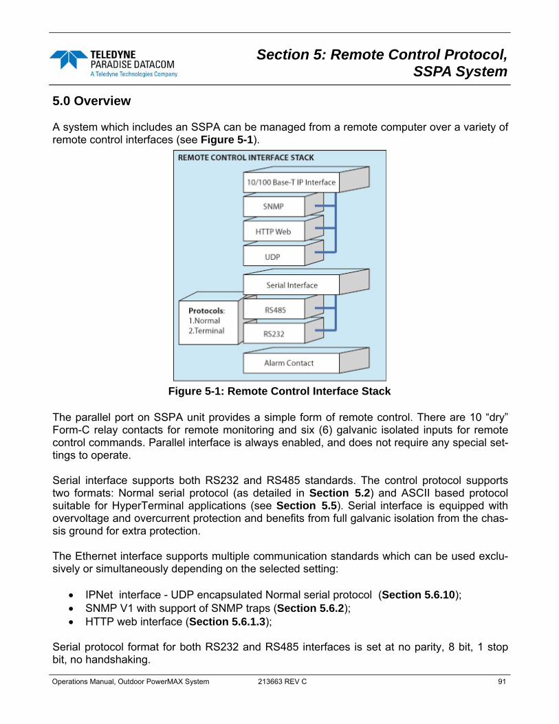
Operations Manual, Outdoor PowerMAX System 213663 REV C 91
Section 5: Remote Control Protocol, SSPA System
5.0 Overview A system which includes an SSPA can be managed from a remote computer over a variety of remote control interfaces (see Figure 5-1).
The parallel port on SSPA unit provides a simple form of remote control. There are 10 “dry” Form-C relay contacts for remote monitoring and six (6) galvanic isolated inputs for remote control commands. Parallel interface is always enabled, and does not require any special set-tings to operate. Serial interface supports both RS232 and RS485 standards. The control protocol supports two formats: Normal serial protocol (as detailed in Section 5.2) and ASCII based protocol suitable for HyperTerminal applications (see Section 5.5). Serial interface is equipped with overvoltage and overcurrent protection and benefits from full galvanic isolation from the chas-sis ground for extra protection. The Ethernet interface supports multiple communication standards which can be used exclu-sively or simultaneously depending on the selected setting:
• IPNet interface - UDP encapsulated Normal serial protocol (Section 5.6.10); • SNMP V1 with support of SNMP traps (Section 5.6.2); • HTTP web interface (Section 5.6.1.3);
Serial protocol format for both RS232 and RS485 interfaces is set at no parity, 8 bit, 1 stop bit, no handshaking.
Figure 5-1: Remote Control Interface Stack

92 213663 REV C Operations Manual, Outdoor PowerMAX System
If using a Terminal mode protocol, the SSPA provides remote menu access through a Hyper-Terminal program or through an actual hardware terminal. The Ethernet interface is fixed to the 10Base-T standard. Normally, straight-through CAT5 ca-ble is used to connect the SSPA to a network hub, and crossover CAT5 is used to connect directly to a computer’s Ethernet port. J4 connector for RS232 utilizes standard DCE 9 pin pin-out (straight through cable requires for connecting to remote PC RS232 port). For this interface maximum cable run of 100 feet can be achieved for 9600 Baud and lower speed rates with quality ground shield cable. RS485 interface pin out is compatible with most 9 pin RS485 adapters. Interface always works in half-duplex mode and suitable for either 4 or 2 wire RS485 configuration. Maximum achievable node length for this interface is 1500 feet. Proper termination and use of shielded twisted pair cable is required to achieve long cable runs. Ethernet interface is auto selectable between 10 and 100 Mbit/s speeds. Maximum node length is 100 feet. Use of CAT5E or CAT6 cables are preferred. CAT5 cable can be used for 10Base-T standard or short runs of 100Base-T. Digicor5 digital platform controller allows simulations support of multiple remote control inter-faces. Table 5-1 shows a list of enabled interfaces depending on chosen interfaces setting.
Serial protocol is an independent selection and allows support of Normal or Terminal mode protocols. Operation over IP interface remains unchanged regardless of serial protocol selec-tion.
Interface Selection
Supported IP Interface
RS232 IPNet, Web M&C (read/write), SNMP (read/write)
RS485 IPNet, Web M&C (read/write), SNMP (read/write)
IPNet IPNet, Web M&C (read/write), SNMP (read only)
SNMP Web M&C (read only), SNMP (read/write)
Table 5-1: Interfaces Enabled Based on Chosen Interface Setting Selection
Supported Serial Interface
RS232
RS485
RS485
RS485

Operations Manual, Outdoor PowerMAX System 213663 REV C 93
5.1 Remote Control - Parallel 5.1.1 Control Outputs The hardware behind the form C relay is a single pole, double throw relay. Under normal operation (no alarms) the relays are in an energized state. When a fault occurs or the controller is powered off, the relays are in a de-energized state. The relay contacts are capa-ble of handling a maximum of 30 VDC @ 1A . The form C relay is shown schematically in Fig-ure 5-2. The form C relay contact outputs are listed in Table 2-2.
5.1.2 Control Inputs All parallel control inputs feature galvanic isolation from the chassis ground. Pull up resistors are provided on each input. To trigger a remote input command, the input should be pulled to port signal ground. All inputs except the Auxiliary fault input are pulse activated. Pulse rele-vant pin to signal ground (J7 pin 19) for at least 20mS for function activation. For example: To change the current mute state of the SSPA to opposite, provide momentary connection for at least 20 mS between pin 17 (Mute Input) of 37-pin connector J7 to pin 19 (Signal Ground). Subsequent pulses will be ignored until Mute state is changed to opposite. Typical time for command propagation depends on type of SSPA and can vary from 100 to 500 mS. Current Mute state can be monitored by dry Form-C relay contacts 4-23-5. Auxiliary input is level activated. Auxiliary input function and logic is user selectable through the front panel or over remote interface. Mute input is set up to be pulse activated by default. However, by special request it could be changed to level activated (Mute on Low or High logic levels). Contact Teledyne Paradise Datacom if you need Mute activation logic different than the default.
Common
Relay Energized
Closed on Fault
Open on Fault
Common
Relay de-Energized
Closed on Fault
Open on Fault
Figure 5-2: Parallel I/O Form C Relay

94 213663 REV C Operations Manual, Outdoor PowerMAX System
5.2 Serial Communication Protocol This section describes the basic serial communication protocol between the SSPA and host computer. The amplifier will only respond to properly formatted protocol packets. The basic communication packet is shown in Figure 5-3. It consists of a Header, Data and Trailer sub-packet.
5.2.1 Header Sub-Packet The Header packet is divided into 3 sub-packets which are the Frame Sync, Destination Ad-dress and Source Address packets (See Figure 5-4).
5.2.1.1 Frame Sync Word The Frame Sync word is a two byte field that marks the beginning of a packet. This value is always 0xAA55. This field provides a means of designating a specific amplifier packet from others that may exist on the same network. It also provides a mechanism for a node to syn-chronize to a known point of transmission. 5.2.1.2 Destination Address The destination address field specifies the node for which the packet is intended. It may be an individual or broadcast address. The broadcast address is 0xFF. This is used when a packet of information is intended for several nodes on the network. The broadcast address can be used in a single device connection when the host needs to determine the address of the am-plifier. The amplifier will reply with its unique address. 5.2.1.3 Source Address The source address specifies the address of the node that is sending the packet. All unique addresses, except the broadcast address, are equal and can be assigned to individual units. The host computer must also have a unique network address.
HEADER (4 bytes)
DATA (6-32 bytes)
Figure 5-3: Basic Communication Packet
TRAILER (1 byte)
HEADER (4 bytes)
DATA (6-32 bytes)
TRAILER (1 byte)
Frame Sync (2 bytes) 0xAA5
Destination Address (1 byte)
Source Address (1 byte)
Figure 5-4: Header Sub-Packet

Operations Manual, Outdoor PowerMAX System 213663 REV C 95
5.2.2 Data Packet The data sub-packet is comprised of 6 to 32 bytes of information. It is further divided into sev-en (7) fields as shown in Figure 5-5. The first six (6) fields comprise the command preamble while the last field is the actual data.
5.2.2.1 Protocol ID This field provides backward compatibility with older generation equipment protocol. It should normally be set to zero (0). This field allows the amplifier to auto-detect other firmware ver-sions. 5.2.2.2 Request ID This is an application specific field. The amplifier will echo this byte back in the response frame without change. This byte serves as a request tracking feature. 5.2.2.3 Command This one byte field tells the receiver how to use the attached data. There are four (4) possible values for this field. The sender and receiver are limited to two commands. For example: if the sender issued “Set Request” command, receiver must answer with “Get Request” and “Get Response” form of the command. The byte value for each command is given in Table 5-2.
HEADER (4 bytes)
DATA (6-32 bytes)
TRAILER (1 byte)
DATA FIELD
Protocol ID 1 Byte
Request ID 1 Byte
Command 1 Byte
Data Tag 1 Byte
Error Status / Data Address
1 Byte
Data Length 1 Byte
Command Data Sub Structure 0 - 26 Bytes
COMMAND PREAMBLE
Command Name Command Byte Value Set Request 0
Get Request 1
Set Response 2
Get Response 3
Table 5-2: Command Byte Values
Figure 5-5: Data Sub-Packet

96 213663 REV C Operations Manual, Outdoor PowerMAX System
5.2.2.4 Data Tag The data tag specifies the type of internal resource of information needed to be accessed on the amplifier. The data associated with certain tags is read only. Therefore, only the “Get” command byte would be associated with these data tags. The data tag byte values are given in Table 5-3.
5.2.2.5 Error Status / Data Address This byte is a tag extension byte and specifies the first data element of the tagged data. If the Data Length is more than 1 byte, then all subsequent data fields must be accessed starting from the specified address. For example, if the requester wants to access the amplifier’s unique network address, it should set data tag 0 (Systems settings tag) and data address 8 (see Systems Settings Details table). If the following Data Length field is more than one (1), then all subsequent Settings will be accessed after the Unique Network Address. When the Response Frame Data Address is omitted, this byte position is replaced with the Error Status fields. The various error codes are given in Table 5-4. Note that the Request and Response frames are different.
Tag Name Byte Value
Minimum valid length of Data Field
Description
System Tag Settings 0 1 byte
This tag allows accessing various system settings on remote unit. Host access status: Full Read/Write access. Settings can be modified at any time. Some settings may require hardware reset of the remote SSPA unit.
System Threshold Tag 1 2 bytes
This tag allows access to the critical unit thresh-olds. Host access status: Read Only access. New thresholds are in effect immediately after change.
System Conditions Tag 3 1 byte
This tag allows access to the unit’s internal condi-tions flags, such as fault status or current system status. Host access status: Read only. This type of data cannot be set or modified remotely.
ADC Channels Access Tag 4 2 bytes
This tag allows access to the unit’s internal Ana-log to Digital converter. Host access status: Read only. This type of data cannot be set or modified remotely.
Reserved 2 N/A This tag is reserved.
Table 5-3: Data Tag Byte Values
Reserved 5 N/A This tag is reserved for factory use only.
Packet Wrapper 6 1 byte See Section 8.3.

Operations Manual, Outdoor PowerMAX System 213663 REV C 97
5.2.2.6 Data Length This byte contains different information for Request and Response frames. In a Request frame, it specifies the number of data bytes that are to be accessed starting from the first byte of the value specified in the Data Address byte. That byte must not exceed the maximum data bytes from a particular tag. The maximum data length for the Settings tag is 26 bytes. The maximum data length for the System Threshold tag is six (6) bytes. 5.2.2.7 Data Field The actual data contained in the packet must be placed in this field. The “Get Request” type of command must not contain any Data Field. Any “Get Request” will be rejected if any data is present in the Data Field. Generally, the Bad Checksum error code will be added to the re-sponse from the amplifier if the word size of the information is 16-bits or 2-bytes. Each data word is placed in the frame with its least significant byte first. All data with length of 2 bytes must be represented as integer type with maximum value range from 32767 to (-32767).
Error Code Name Byte Value Possible Cause No Errors 0 Normal Condition, no errors detected
Data Frame Too Big 1 Specified Data length is too big for buffer to accept
No Such Data 2 Specified Data Address is out of bounds for this tag data
Bad Value 3 Specified value not suitable for this particular data type
Read Only 4 Originator tried to set a value which has read only status
Bad Checksum 5 Trailer checksum not matched to calculated checksum
Unrecognizable Error 6 Error presented in incoming framed, but SSPA failed to recognize it. All data aborted
Table 5-4: Error Status Byte Values

98 213663 REV C Operations Manual, Outdoor PowerMAX System
5.2.3 Trailer Packet The trailer component contains only one (1) byte called the Frame Check Sequence, shown in Figure 5-6.
5.2.3.1 Frame Check This field provides a checksum during packet transmission. This value is computed as a func-tion of the content of the destination address, source address and all Command Data Sub-structure bytes. In general, the sender formats a message frame, calculates the check se-quence, appends it to the frame, then transmits the packet. Upon receipt, the destination node recalculates the check sequence and compares it to the check sequence embedded in the frame. If the check sequences are the same, the data was transmitted without error. Oth-erwise an error has occurred and some form of recovery should take place. In this case, the amplifier will return a packet with the “Bad Checksum” error code set. Checksums are gener-ated by summing the value of each byte in the packet while ignoring any carry bits. A simple algorithm is given as: Chksum=0 FOR byte_index=0 TO byte_index=packet_len-1 Chksum=(chksum+BYTE[byte_index]) MOD 256 NEXT byte_index 5.2.4 Timing issues There is no maximum specification on the inter-character spacing in messages. Bytes in mes-sages to amplifier units may be spaced as far apart as you wish. The amplifier will respond as soon as it has collected enough bytes to determine the message. Generally, there will be no spacing between characters in replies generated by unites. The maximum length of the pack-et sent to the amplifier node should not exceed 64 bytes, including checksum and frame sync bytes. Inter-message spacing must be provided for good data transmission. The minimum spacing should be 100 ms. This time is required for the controller to detect a “Line Cleared” condition with half duplex communications. Maximum controller respond time is 200 ms.
HEADER (4 bytes)
DATA (6-32 bytes)
TRAILER (1 byte)
Frame Check Checksum (1 byte)
Figure 5-6: Trailer Sub-Packet
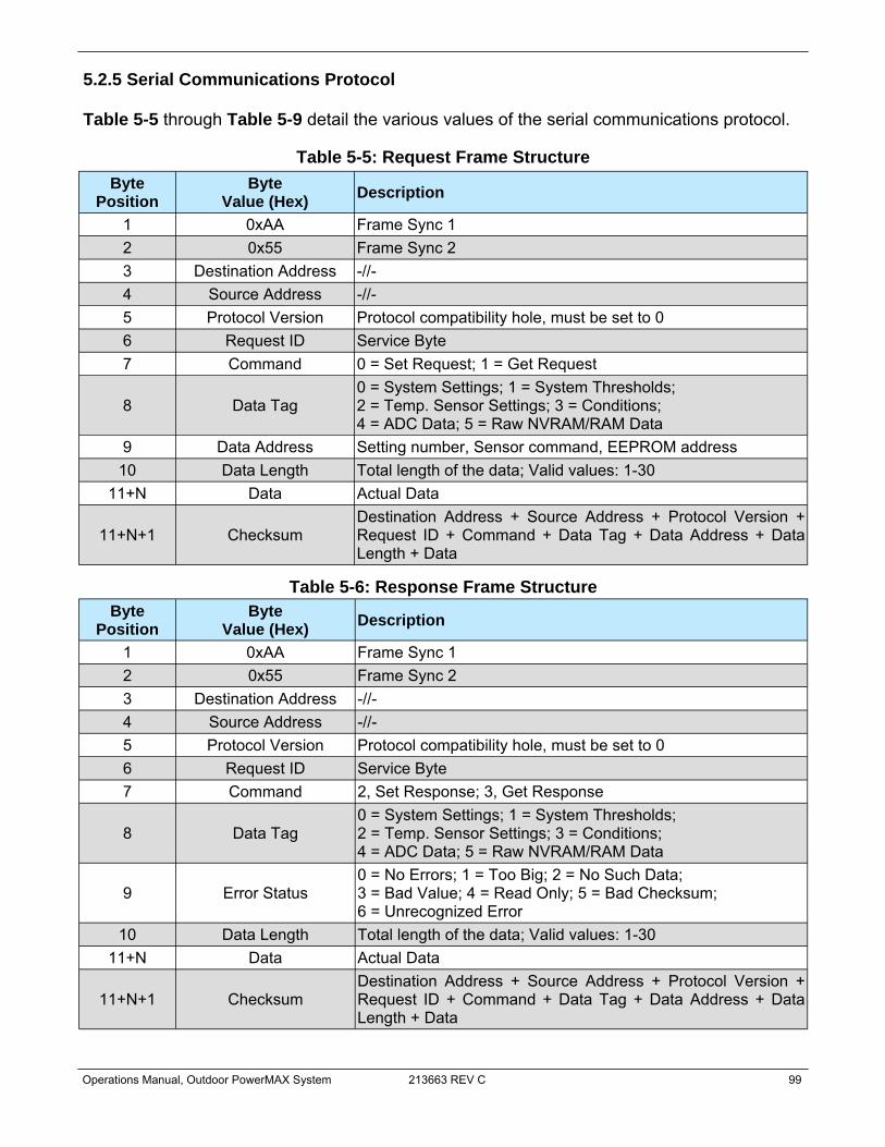
Operations Manual, Outdoor PowerMAX System 213663 REV C 99
5.2.5 Serial Communications Protocol Table 5-5 through Table 5-9 detail the various values of the serial communications protocol.
Byte Position
Byte Value (Hex) Description
1 0xAA Frame Sync 1 2 0x55 Frame Sync 2 3 Destination Address -//- 4 Source Address -//- 5 Protocol Version Protocol compatibility hole, must be set to 0 6 Request ID Service Byte 7 Command 0 = Set Request; 1 = Get Request
8 Data Tag 0 = System Settings; 1 = System Thresholds; 2 = Temp. Sensor Settings; 3 = Conditions; 4 = ADC Data; 5 = Raw NVRAM/RAM Data
9 Data Address Setting number, Sensor command, EEPROM address 10 Data Length Total length of the data; Valid values: 1-30
11+N Data Actual Data
11+N+1 Checksum Destination Address + Source Address + Protocol Version + Request ID + Command + Data Tag + Data Address + Data Length + Data
Table 5-5: Request Frame Structure
Byte Position
Byte Value (Hex) Description
1 0xAA Frame Sync 1 2 0x55 Frame Sync 2 3 Destination Address -//- 4 Source Address -//- 5 Protocol Version Protocol compatibility hole, must be set to 0 6 Request ID Service Byte 7 Command 2, Set Response; 3, Get Response
8 Data Tag 0 = System Settings; 1 = System Thresholds; 2 = Temp. Sensor Settings; 3 = Conditions; 4 = ADC Data; 5 = Raw NVRAM/RAM Data
9 Error Status 0 = No Errors; 1 = Too Big; 2 = No Such Data; 3 = Bad Value; 4 = Read Only; 5 = Bad Checksum; 6 = Unrecognized Error
10 Data Length Total length of the data; Valid values: 1-30 11+N Data Actual Data
11+N+1 Checksum Destination Address + Source Address + Protocol Version + Request ID + Command + Data Tag + Data Address + Data Length + Data
Table 5-6: Response Frame Structure

100 213663 REV C Operations Manual, Outdoor PowerMAX System
Table 5-7: System Setting Details
Data Address
Min. Data Length (bytes)
Description Limits and valid values
0 1 Device Type (read only)
0 = Reserved; 1 = RM SSPA; 2 = CO SSPA; 3 = RCP2/FPRC; 4 = RCP2-1000-CO; 5 = RCP2-1000-RM; 6 = RCP2-1000-RCP; 7 = VSAT BUC=7 (Version 4.00*)
1 1 System Operational Mode Designator
0 = Standalone Mode; 1 = 1:1 Redundant Mode; 2 = 1:2 Redundant Mode; 3 = 1:1 Phase Combined (v. 4.70); 4 = 1:2 Phase Combined (v. 4.98); 5 = Maintenance Switch (v. 6.00*)
2 1 System Switch Mode 0 = Auto; 1 = Manual; 2 = Switch Lock 3 1 Control Mode 0 = Local; 1 = Remote 4 1 Fan Speed 0 = Low; 1 = High; 2 = Auto 5 1 Mute 0 = Mute OFF; 1 = Mute ON
6 1 Serial Protocol Select
0 = Normal; 1 = Terminal Mode; 2 = Locus (No longer supported, beginning with v. 4.00)
7 1 Baud Rate 0 = 9600; 1 = 2400; 2 = 4800; 3 = 19200; 4 = 38400 8 1 Network Address Valid Values: 0 - 255
9 1 Serial Interface 0 = RS232; 1 = RS485; 2 = IPNet (v. 2.50*); 3 = SNMP (v. 4.00*)
10 1 Auxiliary Fault Handling 0 = Disable Fault Checking; 1 = Major Fault; 2 = Minor Fault; 3 = Major Fault + SSPA Mute
11 1 Auxiliary Fault Logic 0 = Fault on Logic High; 1 = Fault on Logic Low
12 1 RF Switch Fault Handling
0 = Disable Fault Checking; 1 = Major Fault; 2 = Minor Fault; 3 = Mute on Switch
13 1 Fault Latch 0 = Disable; 1 = Enable
14 1 BUC Fault Handling
0 = Disable Fault Checking; 1 = Major Fault; 2 = Minor Fault; 3 = Major Fault + SSPA Mute
15 1 BUC Fault Logic 0 = Fault on Logic High; 1 = Fault on Logic Low 16 1 User Password Valid Values: 0 - 255 17 1 Standby Select 0 = Standby; 1 = Online 18 1 Buzzer 0 = Disable; 1 = Enable 19 1 Menu Password Protection 0 = Disable; 1 = Enable 20 1 RF Units 0 = dBm; 1 = Watts (v. 3.40*)
* Version numbers listed indicate the version in which the listed feature was introduced. (Continued)
22 1 HPA Status 0 = HPA1; 1 = HPA2; 2 = HPA3 (v. 3.10*; 1:2 mode only) 21 1 Standby Mode 0 = Hot Standby; 1 = Cold Standby
23 1 Priority Select (1:2 mode) 0 = Pol1; 1 = Pol2 (v. 3.10*)
24 1 Fwd. RF Flt Handling
0 = Disable; 1 = Low RF Major Fault; 2 = Low RF Minor Fault; 3 = ALC; 4 = High RF Major Fault (v. 6.14); 5 = High RF Minor Fault (v. 6.14); 6 = High RF Fault + Mute (v. 6.14)
25 1 Hi Refl. RF Flt Handling 0 = Disable; 1 = Major Fault; 2 = Minor Fault 26 1 SSPA Attenuation Valid values: 0 - 200; 0.1 dBm per 1 value 27 1 Low Fwd RF Threshold Valid values: 0 - 80; 1 dBm per 1 value 28 1 High Refl. RF Threshold Valid values: 0 - 80; 1 dBm per 1 value

Operations Manual, Outdoor PowerMAX System 213663 REV C 101
Table 5-7: System Setting Details (continued from previous page)
Data Address
Min. Data Length (bytes)
Description Limits and valid values
29 1 IP Address Byte 1 (MSB)
These fields are available only for RM SSPA with Ethernet IP Option (See Table 5-9, Field 20 Digital Core Board ID Byte for details) (v. 2.50*)
30 1 IP Address Byte 2
31 1 IP Address Byte 3
32 1 IP Address Byte 4
33 1 IP Gateway Byte 1
34 1 IP Gateway Byte 2
35 1 IP Gateway Byte 3
36 1 IP Gateway Byte 4 (LSB)
37 1 Subnet Mask Byte 1 (MSB)
38 1 Subnet Mask Byte 2
39 1 Subnet Mask Byte 3
40 1 Subnet Mask Byte 4 (LSB)
41 1 Receive IP Port Byte 1 (MSB)
42 1 Receive IP Port Byte 2 (LSB)
43 1 IP Lock Address Byte 1 (MSB)
44 1 IP Lock Address Byte 2
45 1 IP Lock Address Byte 3
46 1 IP Lock Address Byte 4 (LSB)
47 1 N+1 Array size
0 = N+1 disabled; 2 = Array of two SSPAs; 4 = Array of four SSPAs; 8 = Array of eight SSPAs; 16 = Array of 16 SSPAs; Any other numeric value is invalid. (v. 4.20*)
48 1 N+1 Priority Address
Valid range (Array of 2): 1 to 2; Valid range (Array of 4): 1 to 4; Valid range (Array of 8): 1 to 8; Valid range (Array of 16): 1 to 16; (v. 4.20*)
49 1 N+1 Auto Gain Option 0 = Auto Gain Off; 1 = Auto Gain On (v. 4.20)*; 2 = Keep Alive (v. 4.67)*; 3 = FlexGain (v. 4.78)*; 4 = OPMAX Select (v 6.31)*
50 1 N+1 Attenuation Valid values: 0 - 200; 0.1 dBm per 1 value
51 1 Master IP Address Byte 1 Valid Values: 0 - 255 (v. 6.00)
52 1 Master IP Address Byte 2 Valid Values: 0 - 255 (v. 6.00)
53 1 Master IP Address Byte 3 Valid Values: 0 - 255 (v. 6.00)
54 1 Master IP Address Byte 4 Valid Values: 0 - 255 (v. 6.00) 55 1 Floating N+1 Master Mode 0 = Disable; 1 = Enable (v. 6.00)
56 1 Floating N+1 Master Serial Address Valid Values: 0 - 255 (v. 6.00)
* Version numbers listed indicate the version in which the listed feature was introduced.

102 213663 REV C Operations Manual, Outdoor PowerMAX System
Table 5-8: System Threshold Addressing Details (Read Only)
Data Address
Min. Data Length (bytes)
Description Limits and valid values
1 2 Forward RF power If RF Units (Table 5-7, Data Address 20) = 0, then 0.1 dBm per 1 value; If RF Units = 1, then 0.1 Watt per 1 value (v. 3.40*)
2 2 Reflected RF power If RF Units (Table 5-7, Data Address 20) = 0, then 0.1 dBm per 1 value; If RF Units = 1, then 0.1 Watt per 1 value (v. 3.40*)
3 2 SSPA DC Current 0.1 A per 1 value; Value will return (-100) if reading is not available at this time.
4 2 Main Power Supply 1 Output Voltage
0.1 V per 1 value; Value will return (-100) if reading is not available at this time.
5 2 Main Power Supply 2 Output Voltage
0.1 V per 1 value; Value will return (-100) if reading is not available at this time.
6 2 Booster Power Supply 1 Output Voltage
0.1 V per 1 value; Value will return (-100) if reading is not available at this time.
7 2 Booster Power Supply 2 Output Voltage
0.1 V per 1 value; Value will return (-100) if reading is not available at this time.
8 2 SSPA Core Temperature 1 °C per 1 value; Value will return (-100) if reading is not available at this time.
* Version numbers listed indicate the version in which the listed feature was introduced.
12 2 Cabinet Temperature 1 °C per 1 value; Value will return (-100) if reading is not available at this time. v. 4.40*.
11 2 N+1 System Reflected Power
(available from Master unit only!)
If RF Units (Table 5-7, Data Address 20) = 0, then 0.1 dBm per 1 value; If RF Units = 1, then 1 Watt per 1 Value. Value will return (-100) if reading is not available at this time. v. 4.20*.
9 2 N+1 System Forward Power (available from Master unit
only!)
If RF Units (Table 5-7, Data Address 20) = 0, then 0.1 dBm per 1 value; If RF Units = 1, then 1 Watt per 1 Value. Value will return (-100) if reading is not available at this time. v. 4.20*.
10 2 N+1 Estimated System Gain (available from Master only!)
0.1 dB per Value. Estimated N+1 system linear gain. v. 4.20*.
15 2 Chassis Temperature 1 °C per 1 value; Value will return (-100) if reading is not available at this time. v. 6.00*.
14 2 BUC PS2 Voltage 0.1 V per 1 value; Value will return (-100) if reading is not available at this time. v. 6.00*.
13 2 BUC PS1 Voltage 0.1 V per 1 value; Value will return (-100) if reading is not available at this time. v. 6.00*.
Note: In general, data length must be at least two (2) bytes to form an integer; the lower byte must come first. If an odd number of bytes arrived, the last data byte in the packet will be saved as the lower part of the integer; the upper part will be 0 by default.
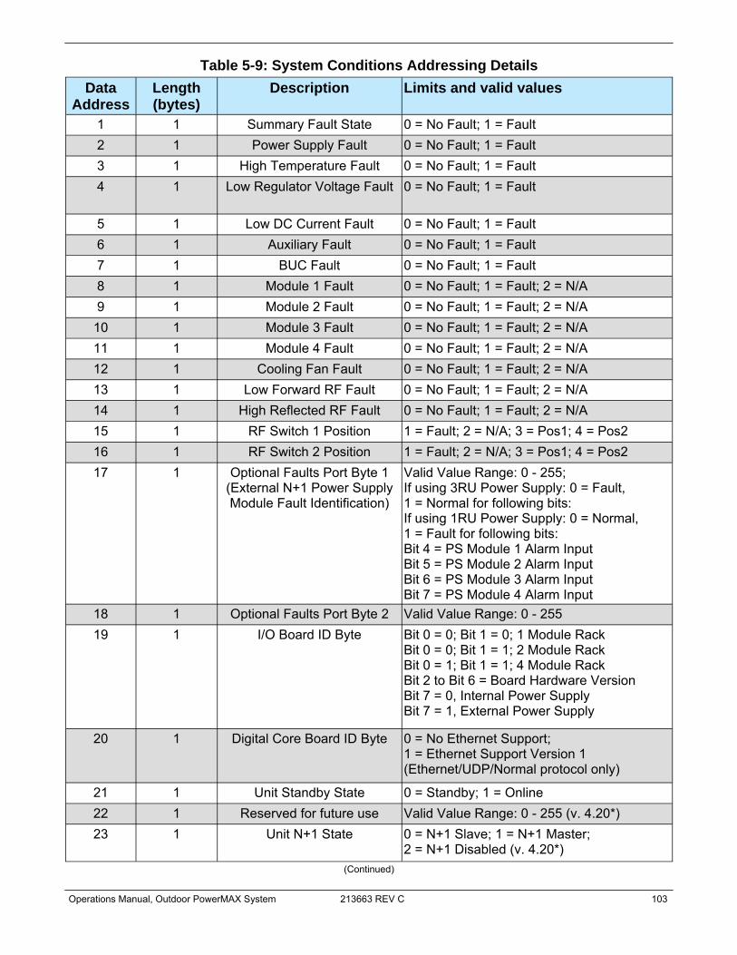
Operations Manual, Outdoor PowerMAX System 213663 REV C 103
Table 5-9: System Conditions Addressing Details Data
Address Length (bytes)
Description Limits and valid values
1 1 Summary Fault State 0 = No Fault; 1 = Fault 2 1 Power Supply Fault 0 = No Fault; 1 = Fault 3 1 High Temperature Fault 0 = No Fault; 1 = Fault 4 1 Low Regulator Voltage Fault 0 = No Fault; 1 = Fault
5 1 Low DC Current Fault 0 = No Fault; 1 = Fault 6 1 Auxiliary Fault 0 = No Fault; 1 = Fault 7 1 BUC Fault 0 = No Fault; 1 = Fault 8 1 Module 1 Fault 0 = No Fault; 1 = Fault; 2 = N/A 9 1 Module 2 Fault 0 = No Fault; 1 = Fault; 2 = N/A
10 1 Module 3 Fault 0 = No Fault; 1 = Fault; 2 = N/A 11 1 Module 4 Fault 0 = No Fault; 1 = Fault; 2 = N/A 12 1 Cooling Fan Fault 0 = No Fault; 1 = Fault; 2 = N/A 13 1 Low Forward RF Fault 0 = No Fault; 1 = Fault; 2 = N/A 14 1 High Reflected RF Fault 0 = No Fault; 1 = Fault; 2 = N/A 15 1 RF Switch 1 Position 1 = Fault; 2 = N/A; 3 = Pos1; 4 = Pos2 16 1 RF Switch 2 Position 1 = Fault; 2 = N/A; 3 = Pos1; 4 = Pos2 17 1 Optional Faults Port Byte 1
(External N+1 Power Supply Module Fault Identification)
Valid Value Range: 0 - 255; If using 3RU Power Supply: 0 = Fault, 1 = Normal for following bits: If using 1RU Power Supply: 0 = Normal, 1 = Fault for following bits: Bit 4 = PS Module 1 Alarm Input Bit 5 = PS Module 2 Alarm Input Bit 6 = PS Module 3 Alarm Input Bit 7 = PS Module 4 Alarm Input
18 1 Optional Faults Port Byte 2 Valid Value Range: 0 - 255 19 1 I/O Board ID Byte Bit 0 = 0; Bit 1 = 0; 1 Module Rack
Bit 0 = 0; Bit 1 = 1; 2 Module Rack Bit 0 = 1; Bit 1 = 1; 4 Module Rack Bit 2 to Bit 6 = Board Hardware Version Bit 7 = 0, Internal Power Supply Bit 7 = 1, External Power Supply
20 1 Digital Core Board ID Byte 0 = No Ethernet Support; 1 = Ethernet Support Version 1 (Ethernet/UDP/Normal protocol only)
21 1 Unit Standby State 0 = Standby; 1 = Online 22 1 Reserved for future use Valid Value Range: 0 - 255 (v. 4.20*) 23 1 Unit N+1 State 0 = N+1 Slave; 1 = N+1 Master;
2 = N+1 Disabled (v. 4.20*) (Continued)

104 213663 REV C Operations Manual, Outdoor PowerMAX System
Table 5-9: System Conditions Addressing Details (continued) Data
Address Min. Data Length (bytes)
Description Limits and valid values
24 1 Cabinet Impeller Fault No Fault = 0; Fault = 1; N/A = 2 (v. 4.40*)
25 1 N+1 System faults (for N+1 Master unit only)
0 to 15, depending on number of faulted N+1 SSPA units and N+1 array size; Fault detection disabled (Slave unit)=255 (v. 4.20*)
26 1 Selected SSPA attenuation. Shows real SSPA attenuation in ALC or N+1 auto gain mode
0.1 dB per 1 Value
27 1 Reserved for factory use 0 - 255 (v. 4.40*) 28 1 Reserved for factory use 0 - 255 (v. 4.40*) 29 1 PreAmp Fault 0 = No Fault; 1 = Fault; 2 = N/A;
3 = Com Error (v. 4.64*) 30 1 N+1 Total offline units count.
Include faulted units and units in standby mode (in case of
switched redundancy schema implemented along with N+1
redundancy.
0 to 15, depending on number of faulted and standby units and N+1 array size. Slave unit = 255 (v. 4.70*)
31 1 Fault Mute State 0 = Fault Mute Off; 1 = Fault Mute On
32 1 Fault Mute Cause 0 = None; 1 = Auxiliary Fault; 2 = External Mute Input; 3 = BUC Fault; 4 = PS Fault; 5 = N+1 Fault (v. 6.00*)
33 1 Last Detected Fault Cause 1 = Cold Start; 2 = High Temperature; 3 = Low Regulator Voltage; 4 = Low DC Current; 5 = Aux Fault; 6 = BUC Fault; 7 = Low Forward RF; 8 = High Reflected RF; 11 = N+ 1 Fault; 12 = PS Fault; 14 = Other Fault; 15 = No Faults (v. 6.00*)
34 1 Detected N+1 Module Faults 0 to 6, depending on number of detected faults and type of N+1 power supply. (v. 6.00*)

Operations Manual, Outdoor PowerMAX System 213663 REV C 105
5.3 Access SSPA Subsystem through Packet Wrapper Technique Features introduced in firmware version 4.03 allow send requests directly to a remote SSPA subsystem. In this mode, an RCP unit redirects requests from its Serial Main or Ethernet port to its Local serial port, connected to the SSPA (see Figure 5-7). Packet wrapper requests are associated with longer response times, which have to be accounted in the host M&C soft-ware. This mode can be useful for advanced remote diagnostic of the attached SSPA subsys-tem. All Packet Wrapper request frames must be “Data Set” command requests. Each frame in-tended for redirection must be included in request packet Data Fields. Packet Wrapping frame M&C should follow the same rules as for any other request frames with one exclusion — the Data Address field will represent the number of bytes expected back from the remote SSPA. These bytes will be redirected back to the Host M&C in the Data Field response packet. The response packet will not be sent until the specified number of bytes is collected in the RCP unit buffer. Maximum length of the data fields in both directions should not exceed 32 bytes. In the dia-gram represented in Figure 5-7, Request frame A is the Packet Wrapper frame. It contains Request frame B, intended to be redirected to the remote SSPA.
Note: In general, data length must be at least two (2) bytes to form an integer; the lower byte must come first. If an odd number of bytes arrived, the last data byte in the packet will be saved as the lower part of the integer; the upper part will be 0 by default.
Figure 5-7: Packet Wrapper technique
Protocol ID0
Request ID0 to 255
Command0 - 1
Data Tag6
Response Lengthn = 11 + m
Data Length11 to 11 + m
Header4 Bytes
Command Preamble6 Bytes
Request Frame B11 to 11 + n Bytes
Trailer Checksum1 Byte
Request Frame A
Protocol ID0
Request ID0 to 255
Command0 - 1
Data Tag0 - 4
Data Address0 to 255
Data Lengthm = 1 to 128
Header4 Bytes
Command Preamble6 Bytes
Data Field0 to m Bytes
Trailer Checksum1 Byte
Request Frame B
Protocol ID0
Request ID0 to 255
Command2 - 3
Data Tag6
Error Status0 to 5
Data Length11 + m
Protocol ID0
Request ID0 to 255
Command2 -3
Data Tag0 - 4
Error Status0 to 5
Data Lengthm = 1 to 128
Header4 Bytes
Command Preamble6 Bytes
ResponseFrame B11 + n Bytes
Trailer Checksum1 Byte
Response Frame A
Header4 Bytes
Command Preamble6 Bytes
Data Fieldm Bytes
Trailer Checksum1 Byte
Response Frame B
SSPA Chassis
RCP
Propogation Delay 1-10 mS
Propogation Delay 1-50 mSPropogation Delay 1-50 mS
Host PC
Request Frame A
Response Frame A
Response Frame B
Request Frame B
J5 Local
J4 Main orJ9 Ethernet

106 213663 REV C Operations Manual, Outdoor PowerMAX System
5.4 Example 1 Check SSPA settings Assumptions: SSPA unit unique network address: 5; PC Host unique network address: 10; Request ID: 111; Unit attached to the serial line; PC request string:
Byte Count Value Description 1 170 Frame Sync Byte 1
2 85 Frame Sync Byte 2
3 5 Destination Address of Unit
4 10 Source Address of Request Originating PC Host
5 0 Protocol Version Compatibility. Field must always be “0”.
6 111 Request ID byte is set by originator, will be echoed back by re-spondent.
7 1 Command field for “Get” type of the request
8 0 “System Settings” tag indicates which data from respondent re-quired in response frame
9 1 Data Address field indicates the beginning data address inside of the “System Settiongs” data set to 1 (first element)
10 28 Data Length field indicates how many data bytes of the “System Settings” requested from the unit
11 156 Arithmetic checksum of bytes number 3 through 10

Operations Manual, Outdoor PowerMAX System 213663 REV C 107
SSPA response string: Byte Count Value Description
1 170 Frame Sync Byte 1 2 85 Frame Sync Byte 2 3 10 Destination Address of PC request originator 4 5 Source address of the respondent 5 0 Protocol Version Compatibility Field must be always 0 6 111 Echo of the Originator's Request ID byte 7 3 Command field for “Get” type of the response
8 0 System Settings tag indicates which data from respondent included in response frame
9 0 Data Address field omitted and replaced with Error status code. 0 in this field indi-cates absence of errors
10 28 Data Length field indicates how many data bytes of the “System Settings” request-ed from SSPA
11 1 Data field 1 contains data element 1 of the “System Settings" 12 0 Data field 2 contains data element 2 of the “System Settings" 13 0 Data field 3 contains data element 3 of the “System Settings" 14 3 Data field 4 contains data element 4 of the “System Settings" 15 0 Data field 5 contains data element 5 of the “System Settings" 16 0 Data field 6 contains data element 6 of the “System Settings" 17 0 Data field 7 contains data element 7 of the “System Settings" 18 5 Data field 8 contains data element 8 of the “System Settings" 19 0 Data field 9 contains data element 9 of the “System Settings" 20 0 Data field 10 contains data element 10 of the “System Settings" 21 0 Data field 11 contains data element 11 of the “System Settings" 22 0 Data field 12 contains data element 12 of the “System Settings" 23 0 Data field 13 contains data element 13 of the “System Settings" 24 0 Data field 14 contains data element 14 of the “System Settings" 25 0 Data field 15 contains data element 15 of the “System Settings" 26 0 Data field 16 contains data element 16 of the “System Settings" 27 1 Data field 17 contains data element 17 of the “System Settings" 28 0 Data field 18 contains data element 18 of the “System Settings" 29 0 Data field 19 contains data element 19 of the “System Settings" 30 0 Data field 20 contains data element 20 of the “System Settings" 31 0 Data field 21 contains data element 21 of the “System Settings" 32 0 Data field 22 contains data element 22 of the “System Settings" 33 0 Data field 23 contains data element 23 of the “System Settings" 34 0 Data field 24 contains data element 24 of the “System Settings" 35 0 Data field 25 contains data element 25 of the “System Settings" 36 0 Data field 26 contains data element 26 of the “System Settings" 37 0 Data field 27 contains data element 27 of the “System Settings" 38 40 Data field 28 contains data element 28 of the “System Settings" 39 207 Arithmetic checksum of bytes number 3 through 38

108 213663 REV C Operations Manual, Outdoor PowerMAX System
5.5 Terminal Mode Serial Protocol for Paradise Datacom SSPA The Teledyne Paradise Datacom Rack Mount SSPA utilizes Terminal Mode Serial Protocol (TMSP) as a secondary serial protocol for management and control through a remote serial interface. TMSP allows the user to access internal SSPA functions via a remote ASCII Terminal or its equivalent (such as HyperTerminal for Windows). TMSP is accomplished through either the RS-232 or RS-485, half duplex, serial communication link. US ASCII encoded character strings are used to represent commands and data massages. A remote terminal or controller initiates a communication session and the SSPA Terminal takes action and returns a report of requested status. The SSPA terminal will not initiate com-munication and will transmit data only when commanded to do so. Prior to establishing the session with the SSPA Terminal, this mode must be enabled through the SSPA front panel menu. The remote terminal must be configured with serial settings that match the SSPA’s serial port settings. For example, if the SSPA is set at 9600 Baud, the remote terminal must be also con-figured as ASCII terminal at 9600 Baud, no parity, 8 bit data with 1 stop bit serial connection. The SSPA will not echo back any incoming characters, so local echo must be enabled on the remote terminal. To establish a remote control session with the SSPA terminal, the user must type “UNIT#XXX” in the terminal window (all letters must be in upper case), where XXX is the RM SSPA unique network address or the global call address (255). Press the “Enter” key on re-mote terminal keyboard. The SSPA should answer with “Unit#XXX OnLine”, with the first menu screen on the following lines. After a remote session is successfully established, the unit will stay connected as long as needed. The session interface mimics the SSPA’s front panel menu. To help the user navi-gate through the menu, the help string with the list of active keys always follows the menu strings. For example, the last transmission string on all informative menu screens will be: “Active Keys:(U)p+Enter;(D)own+Enter;(C)lrearFlt; (M)enu+Enter; (E)nd+Enter”.
Note: All letters must be in upper case! To refresh the current screen on the remote terminal, press the “Enter” key. To end a session, press “E” and the “Enter” key.
Important! If multiple SSPA units are networked on the same serial link. DO NOT ESTABLISH A SESSION WITH MORE THAN ONE SSPA AT THE SAME TIME. If you do so you will not get any valid answer from the SSPA!
Figure 5-8 shows an example screen shot of a terminal session.

Operations Manual, Outdoor PowerMAX System 213663 REV C 109
Figure 5-8: Terminal Mode Session Example

110 213663 REV C Operations Manual, Outdoor PowerMAX System
5.6 Ethernet Interface The rack mount SSPA Ethernet Port (J9) supports several IP network protocols to provide a full-featured remote M&C interface over an Ethernet LAN.
• IPNet protocol – Redirection of standard Teledyne Paradise Datacom serial protocol over UDP transport layer protocol. This protocol is fully supported in the Teledyne Paradise Datacom Universal M&C software.
• SNMPv1 protocol - This protocol is intended for integration into large corporate NMS architectures.
In order to utilize either of the protocols listed above, the relevant interface option has to be turned on. Refer to Section 5.6.1.2 and Section 5.6.2.4 for details. Of course, standard IP level functions such as ICMP Ping and ARP are supported as well. There is currently no support for dynamic IP settings, all IP parameters. 5.6.1 IPNet Interface 5.6.1.1 General Concept Satcom system integrators are recognizing the benefits of an Ethernet IP interface. These benefits include:
• Unsurpassed system integration capabilities; • Widely available and inexpensive set of support equipment (network cable; net-
work hubs); • Ability to control equipment over Internet; • Ease of use
Implementation of the raw Ethernet interface is not practical due to the limitations it places on M&C capabilities by the range of a particular LAN. It is more practical to use an Ethernet inter-face in conjunction with the standard OSI (Open System Interconnect) model to carry a stack of other protocols. In an OSI layered stack, an Ethernet interface can be represented as a Da-ta Link layer. All upper layers are resolved through a set of IP protocols. In order to keep data bandwidth as low as possible (which is important when M&C functions are provided through a low-bandwidth service channel) the IP/UDP protocol set is used as the Network/Transport lay-er protocol on Teledyne Paradise Datacom SSPAs. UDP (User Datagram Protocol) was chosen over TCP (Transmission Control Protocol) be-cause it is connectionless; that is, no end-to-end connection is made between the SSPA unit and controlling workstation when datagrams (packets) are exchanged. Teledyne Paradise Datacom provides a Windows-based control application to establish UDP-based Ethernet communication with SSPAs. The control application manages the exchange of datagrams to ensure error-free communication. An attractive benefit of UDP is that it re-quires low overhead resulting in minimal impact to network performance. The control applica-tion sends a UDP request to SSPA unit and waits for response. The length of time the control

Operations Manual, Outdoor PowerMAX System 213663 REV C 111
application waits depends on how it is configured. If the timeout is reached and the control application has not heard back from the agent, it assumes the packet was lost and retrans-mits the request. The number of the retransmissions is user configurable. The Teledyne Paradise Datacom RM SSPA Ethernet IP interface can use UDP ports from 0 to 65553 for sending and receiving. The receiving port needs to be specified through the front panel menu. For sending, it will use the port from which the UDP request originated. Of course, it is up to the user to select an appropriate pair of ports that are not conflicting with standard IP services. Paradise Datacom recommends usage of ports 1038 and 1039. These ports are not assigned to any known application. As an application layer protocol (which actually carries meaningful data), the standard Tele-dyne Paradise Datacom RM SSPA serial protocol was selected. This protocol is extremely flexible and efficient. It is also media independent and can be easily wrapped into another protocol data frame. An example of the UDP frame with encapsulated Teledyne Paradise Datacom protocol frame is shown in Figure 5-9.
A detailed OSI model for the RM SSPA M&C interface is represented in Table 5-10.
This set of Ethernet IP protocols is currently supported by the Teledyne Paradise Datacom Universal M&C software package. The software is supplied on CD with the unit, or can be download from company's web site, http://www.paradisedata.com.
UDP Header (8 bytes)
SSPA Serial Protocol Frame (11+N Bytes, 0<N<128)
Figure 5-9: UDP Redirect Frame Example
CRC 16 checksum
OSI Layer Protocol Notes
Application Paradise Datacom RM SSPA Serial Protocol
This is the frame structure described in Section 8.1 through Section 8.6.
Transport UDP Connectionless transport service. MTU on target PC must be set to accommodate largest SSPA Serial Proto-col Frame. Set MTU to a value larger than 127 bytes.
Network IP ARP, RARP and ICMP Ping protocols supported by RM SSPA controllers. Static IP Address only, no DHCP sup-port.
Data Link Ethernet 10/100 Base-T Network
Physical Standard CAT5 (CAT 6) Network Cable Maximum node length 100 m
Table 5-10: OSI Model for RM SSPA Ethernet IP Interface

112 213663 REV C Operations Manual, Outdoor PowerMAX System
5.6.1.2 Setting IPNet interface Before enabling the Ethernet IP interface, the following IP parameters need to be set: IP Port address, Default Gateway, Subnet Mask, Receive IP Port and Lock IP address. All IP related menu items consolidate under the Communication Setup menu. Press the Main Menu key, select 2.Com.Setup and press the Enter key, select 5.IP Setup and press the Enter key. The Lock IP address is a security measure. Setting this parameter either to 255.255.255.255 or 0.0.0.0 will allow any host to control the SSPA. Setting the parameter to the specific ad-dress of the remote host will lock SSPA access to this host. Packets received from other hosts will be ignored. For other parameters (IP address, Gateway, Subnet, IP port) contact your network system administrator for assistance.
Important! If you are planning to access the SSPA RM via the Internet, you must exercise appropriate security measures. It is strongly recommended to put SSPA units behind a protective Firewall or set up a VPN link for remote access.
After selecting the IP parameters, turn on IP interfaces: Press the Main Menu key, select 2.Com.Setup and press the Enter key; select 4.Interface and press the Enter key; select 3.IPNet and press the Enter key. Ethernet Interface is now the primary remote control interface and the RS232/485 Main port is disabled. The user may adjust any IP settings when the IPNet interface is turned on, as need-ed, without losing IP link. New settings become effective only after a hardware reset (press the Main Menu key; select 5.Options and press the Enter key; select 6.Reset and press the Enter key; select 3.Coms Only and press the Enter key; or cycle power to the unit). To disable the Ethernet port and enable the RS-232/RS-485 Serial Main port, press the Main Menu key and select 2.Com.Setup, press the Enter key; select 4.Interface, press the Enter key; select either 1.RS232 or 2.RS485, and press the Enter key.
Important! At the present, the RM SSPA controller supports only one remote control protocol selection through its Ethernet interface port. This protocol is referred to as “Normal” on the front panel display (See Section 3.1 through Section 3.6). If the protocol selection is set differently (Terminal), the controller will force its protocol selection to “Normal”.
The RM SSPA Ethernet port can be connected to a network hub using straight through net-work cable or directly to a work station NIC card through a null-modem or cross-over cable (Rx and Tx lines are crossed). As soon as an Ethernet interface has been selected as the pri-mary interface, you should be able to verify the network connection to the unit by using the Ping command from your host workstation. To do so on a Windows based PC, open a Command Prompt window and type PING and the dot delimited IP address of the RM SSPA, then press the Enter key. If the unit is successfully found on the network, the request statistic will be displayed.

Operations Manual, Outdoor PowerMAX System 213663 REV C 113
If the unit does not answer on the ping command, check all hardware connections and verify that the IP settings on your host workstation and the RM SSPA match your network parame-ters. On a Windows-based PC you may also check Address Resolution Protocol (ARP) table entries. The new IP address of the RM SSPA may be set to another PC or network equipment with a different MAC address. Open a Command Prompt window and type “ARP -a”, the press Enter. The current ARP data will be displayed. If you see the RM SSPA IP address entry in the table, delete it by issuing the command “ARP -d XXX.XXX.XXX.XXX” and press Enter (XXX.XXX.XXX.XXX is the IP address of the RM SSPA unit). Try the PING command again. More information about how to set up a network connection with the RM SSPA can be found in Appendix B. 5.6.1.3 Using the Rack Mount Web Interface Starting with firmware version 6.00, the rack mount web interface no longer needs to have a pre-installed Java application to operate. The web interfaces uses a standard hypertext trans-fer protocol on port 80. The web interface is compatible with most modern web browsers, such as Firefox, Chrome or Internet Explorer, which support asynchronous JavaScript XML transactions (aka AJAX). To connect to SSPA internal web page, the user must make sure Web/IPNet interface is ena-bled on the device (See Section 8.6.1.2) and that an IP address has been assigned to the unit. Connect the unit to an Ethernet network or directly to a PC 10/100 Base-T adapter and then open a web browser. Enter IP address of the unit into the address bar of the browser. A security login window will appear. In the User Name field, enter admin, the default User Name. See Figure 5-10. The User Name is fixed and cannot be changed by the operator.
In the Password field, enter the web password assigned to the unit. The factory default pass-word is paradise. The User Name and Password are case sensitive. The password may be changed at any time and may comprise up to 15 alpha-numeric characters.
Figure 5-10: Web Interface Login Window

114 213663 REV C Operations Manual, Outdoor PowerMAX System
Click on the [Log In] button to open the M&C control in the browser window. See Figure 5-11.
The top bar of SSPA Monitor and Control application shows device’s online status, transmit status, RF output power, reflected RF power (if available), attenuation and RF module core temperature. Left side of the window displays unit model and serial number, firmware build, device MAC address and device up time since last I/O card power up or reboot. Additional information is displayed in multipage insert in the middle of the screen:
• Status tab: A view of critical device operation parameters and alarm statuses. • Communication Setup tab: Read/write listings of communication related pa-
rameters, including: IP, SNMP, Web settings as well as serial port settings. • General Settings tab: Read/Write listings of all redundancy and amplifier spe-
cific settings. • Fault Settings tab: Read/Write listing of fault operation related settings; • N+1 tab: page shows N+1 system related operation parameters.
The web server has limited hardware resources to support multiple simultaneously connected users. In the case that multiple users are connected to the same amplifier, service quality cannot be assured.
Figure 5-11: RM SSPA Web Interface, Status Tab

Operations Manual, Outdoor PowerMAX System 213663 REV C 115
5.6.2 SNMP Interface SNMP-based management was initially targeted for TCP/IP routers and hosts. However, the SNMP-based management approach is inherently generic so that it can be used to manage many types of systems. This approach has become increasingly popular for remote manage-ment and control solutions for various SSPA systems. Teledyne Paradise Datacom devices with Ethernet interface support the most popular SNMPv1 format (SMIv1, RFC1155), SNMP Get, SNMP GetNext and SNMP Set commands. SNMP Traps are currently unsupported. In order to utilize SNMP protocol, the operator has to enable this feature through the front panel or by remote serial protocol. SNMP uses the UDP fixed port 161. The definition of managed objects described in the Management Information Base (MIB) file. The MIB file is available for download from the Downloads section of the Teledyne Paradise Datacom web site, http://www.paradisedata.com. 5.6.2.1 Interface The Teledyne Paradise Datacom MIB is a table-based MIB, and is the same for all devices. The MIB table is designed to follow the same pattern as the tables for serial protocol. For ad-ditional information about OID values, refer to Table 5-11 through Table 5-13. The text values in the tables help automatic value parsing within NMS or make the values readable through an MIB browser. All text value OIDs follow the same pattern:
1. For se ngs or parameters with discreet values: Se ngName’ValueName1=xxx, ….,ValueNamex=xxx Example: SystemMode'1:1=0,Dual 1:1 = 1,MSwitch=2,StandAlone=255 2. For se ngs or parameters with con nuous values: Se ngName’LowLimit..HighLimit Example: NetworkAddress'0..255
As with the serial protocol, the MIB allows access to a remote SSPA (default state) as well as to the RCP unit itself. To switch between those devices’ MIBs, the proper Device Type has to be selected (OID -1.3.6.1.4.1.20712.1.4). 5.6.2.2 SNMP V3 issues in Teledyne Paradise Datacom SSPAs Simple Network Management Protocol (SNMP) is an interoperable standards-based protocol that allows for external monitoring of the Content Engine through an SNMP agent. A SNMP-managed network consists of three primary components: managed devices, agents, and management systems. A managed device is a network node that contains a SNMP agent and resides on a managed network. Managed devices collect and store management infor-mation and use SNMP to make this information available to management systems that use SNMP. Managed devices include routers, servers, switches, bridges hubs, computer hosts, and printers.

116 213663 REV C Operations Manual, Outdoor PowerMAX System
An agent is a software module that has local knowledge of management information and translates that information into a form compatible with SNMP: the Management Information Base (MIB). The agent can send traps, or notification of certain events, to the manager. Es-sentially, a Teledyne Paradise Datacom SSPA is considered a “SNMP agent”. A manager is a software module that listens to the SNMP notifications sent by SNMP agents. The manager can also send requests to an agent to collect remote information from the Man-agement Information Base (MIB). The communication between the agent and the manager uses the SNMP protocol, which is an application of the ASN.1 BER (Abstract Syntax Notation 1 with Basic Encoding Rules), typ-ically over UDP (for IP networks).
• Version 1 (SNMPv1, described in RFC 1157) is the initial implementation of SNMP.
• Version 2 (SNMPv2c, described in RFC 1902) is the second release of SNMP. It provides additions to data types, counter size, and protocol operations.
• Version 3 (SNMPv3, described in RFC 2271 through RFC 2275) is the most recent version of SNMP.
SNMP V1 SNMP version 1 (SNMPv1) is the initial implementation of the SNMP protocol. SNMPv1 oper-ates over protocols such as User Datagram Protocol (UDP), Internet Protocol (IP), OSI Con-nectionless Network Service (CLNS), AppleTalk Datagram-Delivery Protocol (DDP), and Novell Internet Packet Exchange (IPX). SNMPv1 is widely used and is the de-facto network-management protocol in the Internet community. The Teledyne Paradise Datacom SSPA family of products utilizes the most popular imple-mentation, SNMP V1 over UDP transport layer. SNMP V2 SNMPv2 (RFC 1441–RFC 1452) revises version 1 and includes some improvements in the areas of performance, security, confidentiality, and manager-to-manager communications. It introduced GetBulkRequest, an alternative to iterative GetNextRequests for retrieving large amounts of management data in a single request. However, the new party-based security system in SNMPv2, viewed by many as overly complex, was not widely accepted. The format of the trap message was also changed in SNMPv2. To avoid these compatibility issues, the trap mechanism was not implemented in the Teledyne Paradise Datacom SSPA MIB. SNMP V3 Although SNMPv3 makes no changes to the protocol aside from the addition of cryptographic security, it looks much different due to new textual conventions, concepts, and terminology. SNMPv3 primarily added security and remote configuration enhancements to SNMP.

Operations Manual, Outdoor PowerMAX System 213663 REV C 117
Many embedded controllers and microprocessors that are used in electronic components such as amplifier modules do not have support for SNMP V2 or V3. This is due to the exten-sive memory resources required by the computation intensive cryptographic security of SNMP V3. For this reason V3 has not gained widespread support amongst embedded MCU platform manufacturers. Existing port implementations are limited to very powerful ARM5 or above cores, running under full-scale OS systems (Linux, Android, etc.). At large, these configura-tions require external bulk RAM/FLASH to operate. This requirement ultimately affects the minimum device startup time (tens of seconds, due to the large boot BIOS) and working tem-perature range (mostly indoor). As noted in Cisco’s release notes about SNMP V3:
SNMP no fica ons can be sent as traps or inform requests. Traps are unreliable because the receiver does not send acknowledgments when this device receives traps. The sender cannot determine if the traps were received. However, an SNMP en ty that receives an inform request acknowledges the message with an SNMP response protocol data unit (PDU). If the sender never receives the response, the inform request can be sent again. Therefore, informs are more likely to reach their intended des na on. However, informs consume more resources in the agent and in the network. Unlike a trap, which is discard‐ed as soon as it is sent, an inform request must be held in memory un l a response is received, or the re‐quest mes out. Traps are sent only once, while an inform can be retried several mes. The retries increase traffic and contribute to a higher overhead on the network.
(h p://www.cisco.com/c/en/us/support/docs/ip/simple‐network‐management‐protocol‐snmp/13506‐snmp‐traps.html, last visited on 22 January 2015.)

118 213663 REV C Operations Manual, Outdoor PowerMAX System
5.6.2.3 SNMP MIB tree --paradiseDatacom(1.3.6.1.4.1.20712) | +--deviceINFO(1) | | | +-- r-n OctetString deviceID(1) | +-- rwn OctetString deviceLocation(2) | +-- r-n OctetString deviceRevision(3) | +-- r-n Enumeration deviceType(4) | +--devices(2) | +--paradiseDevice(1) | | | +--settings(1) | | | | | +--settingsEntry(1) [settingIndex] | | | | | +-- rwn Integer32 settingIndex(1) | | +-- rwn Integer32 settingValue(2) | | +-- r-n OctetString settingTextValue(3) | | | +--thresholds(2) | | | | | +--thresholdsEntry(1) [thresholdIndex] | | | | | +-- rwn Integer32 thresholdIndex(1) | | +-- r-n Integer32 thresholdValue(2) | | +-- r-n Enumeration thresholdStatus(3) | | +-- r-n OctetString thresholdText(4) | | | +--conditions(3) | | | +--conditionsEntry(1) [conditionsIndex] | | | +-- rwn Integer32 conditionsIndex(1) | +-- r-n Integer32 conditionsValue(2) | +-- r-n Counter conditionsEventCount(3) | +-- r-n OctetString conditionsText(4) | +--paradiseDeviceA(2) | +--paradiseDeviceB(3) | +--paradiseDeviceC(4) | +--modem(5)

Operations Manual, Outdoor PowerMAX System 213663 REV C 119
5.6.2.4 Description of MIB entities deviceINFO - This field includes general device information. deviceID - Octet string type; maximum length -60; field specifies device model and serial number; read only access; OID -1.3.6.1.4.1.20712.1.1 deviceLocation - Octet string type; maximum length 60; filed allow customer to store infor-mation about device physical location or any other textual information related to the device; read/write access; OID -1.3.6.1.4.1.20712.1.2 deviceRevision - Octet string type; maximum length 60; field specifies device firmware revi-sion; read only access; OID -1.3.6.1.4.1.20712.1.3 deviceType - Enumeration, integer type; field allows simple detection of SNMP device type. Values: rmsspa(1), cosspa(2), rcp2fprc(3), rcp21000co(4), rcp21000rm(5), rcp21000rcp(6), buc(7), rbc(8), minicosspa(9); read only access; Setting the ID to any other value will default type to cosspa. OID -1.3.6.1.4.1.20712.1.4 devices - This field is subdivided into 5 branches: paradiseDevice, paradiseDeviceA, paradis-eDeviceB paradiseDeviceC and modem. paradiseDevice branch currently is used for all Para-dise Datacom LLC SNMP enabled devices except Modem. See the Evolution Modem manual for specific MIB information. Branches for Devices A, B and C are reserved for future use. paradiseDevice - Field contains tables that hold specific device information: Settings, Thresholds and Conditions. All table formats follow a common pattern: Index, Value, Text-Value. The threshold table has an additional column for parameter validation. The conditions table has an extra column for event counters. The Index column provides general table indexing; the Value column presents the current val-ue of the relevant parameter; the TextValue column provides information about parameter name, measurement units and limits. Value “1” in the validation column of the thresholds table indicates that relevant parameter is valid under the current system configuration; value “2” indicates that parameter is invalid or “Not available”. The event counter column of the conditions table indicates how many times a value of a rele-vant parameter changed its state since system power-up. settings - Table contents current device configuration and provides device management. For detailed settings table info for RM SSPA SNMP device see Table 5-11. Read/write access for settingsValue column. thresholds - Table provides information about device internal limits and subsystems info. For detailed table information refer to Table 5-12. Read only access. conditions - Table contents device fault status information. Read only access. For detailed conditions table info see Table 5-13.

120 213663 REV C Operations Manual, Outdoor PowerMAX System
Table 5-11: SNMP Detailed Settings se
tting
Inde
x/
setti
ngV
alue
se
tting
Text
Valu
e V
alue
OID
D
escr
iptio
n
1/IN
TEG
ER
S
ysM
ode'
Std
Aln
=0,1
:1=1
,1:2
=2,1
:1P
hC=3
,1:2
PhC
=4,
Sin
glS
w=5
1.
3.6.
1.4.
1.20
712.
2.1.
1.1.
2.1
Sys
tem
Ope
ratio
n m
ode
2/IN
TEG
ER
S
witc
hMod
e'A
uto=
0,M
anua
l=1,
SW
Lock
=2
1.3.
6.1.
4.1.
2071
2.2.
1.1.
1.2.
2 R
edun
danc
y sw
itchi
ng m
ode
3/IN
TEG
ER
C
ontro
lMod
e'Lo
cal=
0,R
emot
e=1
1.3.
6.1.
4.1.
2071
2.2.
1.1.
1.2.
3 U
nit c
ontro
l mod
e
4/IN
TEG
ER
Fa
nSpe
ed'L
ow=0
,Hig
h=1,
Auto
=2
1.3.
6.1.
4.1.
2071
2.2.
1.1.
1.2.
4 Fa
n Sp
eed
5/IN
TEG
ER
M
ute'
Off=
0,O
n=1
1.3.
6.1.
4.1.
2071
2.2.
1.1.
1.2.
5 U
nit m
ute
stat
us
6/IN
TEG
ER
P
roto
col'N
orm
al=0
,Ter
min
al=1
1.
3.6.
1.4.
1.20
712.
2.1.
1.1.
2.6
Uni
t rem
ote
cont
rol p
roto
col
7/IN
TEG
ER
Baud
'960
0=0,
2400
=1,4
800=
2,19
200=
3,38
400=
4 1.
3.6.
1.4.
1.20
712.
2.1.
1.1.
2.7
Ser
ial I
nter
face
spe
ed
8/IN
TEG
ER
N
etw
orkA
ddre
ss'0
..255
1.
3.6.
1.4.
1.20
712.
2.1.
1.1.
2.8
Ser
ial i
nter
face
add
ress
9/IN
TEG
ER
In
terfa
ce'R
S23
2=0,
RS
485=
1,IP
Net
=2,S
NM
P=3
1.
3.6.
1.4.
1.20
712.
2.1.
1.1.
2.9
Uni
t rem
ote
cont
rol i
nter
face
10/IN
TEG
ER
Au
xFltH
andl
e'Ig
nore
=0,M
ajor
=1,M
inor
=2,M
ajor
+Mut
e=3,
M
inor
+Mut
e=4
1.3.
6.1.
4.1.
2071
2.2.
1.1.
1.2.
10
Auxi
liary
faul
t han
dlin
g
11/IN
TEG
ER
A
uxFl
tLof
ic'F
aultO
nHig
h=0,
Faul
tOnL
ow=1
1.
3.6.
1.4.
1.20
712.
2.1.
1.1.
2.11
A
uxili
ary
faul
t log
ic
12/IN
TEG
ER
R
FSW
FltH
andl
e'Ig
nore
=0,M
ajor
=1,M
inor
=2,S
wM
ute=
3 1.
3.6.
1.4.
1.20
712.
2.1.
1.1.
2.12
R
F sw
itch
faul
t han
dlin
g
13/IN
TEG
ER
Fa
ultL
atch
'Dis
able
=0,E
nabl
e=1
1.3.
6.1.
4.1.
2071
2.2.
1.1.
1.2.
13
Faul
t lat
ch s
tate
14/IN
TEG
ER
BU
CFl
tHan
dle'
Igno
re=0
,Maj
or=1
,Min
or=2
,Maj
or+M
ute=
3 1.
3.6.
1.4.
1.20
712.
2.1.
1.1.
2.14
In
tern
al B
UC
faul
t han
dlin
g
15/IN
TEG
ER
B
UC
FltL
ofic
'Fau
ltOnH
igh=
0,Fa
ultO
nLow
=1
1.3.
6.1.
4.1.
2071
2.2.
1.1.
1.2.
15
Inte
rnal
BU
C fa
ult l
ogic
16/IN
TEG
ER
U
serP
assw
ord'
0..2
55
1.3.
6.1.
4.1.
2071
2.2.
1.1.
1.2.
16
Num
eric
men
u pa
ssw
ord
17/IN
TEG
ER
S
tartU
pSta
te'S
tand
by=0
,Onl
ine=
1 1.
3.6.
1.4.
1.20
712.
2.1.
1.1.
2.17
R
edun
danc
y on
line/
stan
dby
sele
ctio
n
18/IN
TEG
ER
B
uzze
r'Off=
0,O
n=1
1.3.
6.1.
4.1.
2071
2.2.
1.1.
1.2.
18
Aud
ible
ala
rm s
tate
19/IN
TEG
ER
M
enuP
assw
ord'
Off=
0,O
n=1
1.3.
6.1.
4.1.
2071
2.2.
1.1.
1.2.
19
Men
u pa
ssw
ord
prot
ectio
n
20/IN
TEG
ER
R
FUN
ITS
’dB
m=0
,wat
ts=1
1.
3.6.
1.4.
1.20
712.
2.1.
1.1.
2.20
U
nit
mea
sure
men
t se
lect
(d
Bm
or
W
atts
)
21/IN
TEG
ER
Stan
dbyM
ode'
Hot
Stan
dby=
0,C
oldS
tand
by=1
1.
3.6.
1.4.
1.20
712.
2.1.
1.1.
2.21
R
edun
danc
y st
andb
y m
ode
22/IN
TEG
ER
H
PA
Sta
tus'
HP
A1=
0,H
PA
2=1,
HP
A3=
2 1.
3.6.
1.4.
1.20
712.
2.1.
1.1.
2.22
R
edun
danc
y H
PA s
tatu
s
23/IN
TEG
ER
P
riorit
y'P
ol1=
0,P
ol2=
1 1.
3.6.
1.4.
1.20
712.
2.1.
1.1.
2.23
1:
2 M
ode
prio
rity
sele
ct
24/IN
TEG
ER
Lo
wFr
wrd
RFF
ltHan
dle'
Igno
re=0
,Maj
or=1
,Min
or=2
,ALC
=3
1.3.
6.1.
4.1.
2071
2.2.
1.1.
1.2.
24
Low
forw
ard
RF
faul
t han
dlin
g
25/IN
TEG
ER
H
ighR
efR
FFltH
andl
e'Ig
nore
=0,M
ajor
=1,M
inor
=2
1.3.
6.1.
4.1.
2071
2.2.
1.1.
1.2.
25
Hig
h re
flect
ed R
F fa
ult h
andl
ing

Operations Manual, Outdoor PowerMAX System 213663 REV C 121
Table 5-11: SNMP Detailed Settings (continued from previous page)
setti
ngIn
dex/
se
tting
Val
ue
setti
ngTe
xtVa
lue
Val
ue O
ID
Des
crip
tion
26/IN
TEG
ER
S
SP
AA
ttenu
atio
n(dB
x10)
'0..2
00
1.3.
6.1.
4.1.
2071
2.2.
1.1.
1.2.
26
Uni
t atte
nuat
ion
leve
l 27
/INTE
GE
R
Low
Forw
ardR
Fthr
esho
ld(d
Bm
)'0..8
0 1.
3.6.
1.4.
1.20
712.
2.1.
1.1.
2.27
Lo
w fo
rwar
d R
F th
resh
old
28/IN
TEG
ER
H
ighR
efR
FThr
esho
ld(d
Bm
)'0..8
0 1.
3.6.
1.4.
1.20
712.
2.1.
1.1.
2.28
H
igh
refle
cted
RF
thre
shol
d 29
/INTE
GE
R
IPA
ddre
ssB
yte1
'0..2
55
1.3.
6.1.
4.1.
2071
2.2.
1.1.
1.2.
29
Dev
ice
IP a
ddre
ss b
yte1
(MS
B)
30/IN
TEG
ER
IP
Add
ress
Byt
e2'0
..255
1.
3.6.
1.4.
1.20
712.
2.1.
1.1.
2.30
D
evic
e IP
add
ress
byt
e2
31/IN
TEG
ER
IP
Add
ress
Byt
e3'0
..255
1.
3.6.
1.4.
1.20
712.
2.1.
1.1.
2.31
D
evic
e IP
add
ress
byt
e3
32/IN
TEG
ER
IP
Add
ress
Byt
e4'0
..255
1.
3.6.
1.4.
1.20
712.
2.1.
1.1.
2.32
D
evic
e IP
add
ress
byt
e4 (L
SB
) 33
/INTE
GE
R
IPG
ateW
ayB
yte1
'0..2
55
1.3.
6.1.
4.1.
2071
2.2.
1.1.
1.2.
33
Dev
ice
Gat
eway
add
ress
byt
e1 (M
SB
) 34
/INTE
GE
R
IPG
ateW
ayB
yte2
'0..2
55
1.3.
6.1.
4.1.
2071
2.2.
1.1.
1.2.
34
Dev
ice
Gat
eway
add
ress
byt
e2
35/IN
TEG
ER
IP
Gat
eWay
Byt
e3'0
..255
1.
3.6.
1.4.
1.20
712.
2.1.
1.1.
2.35
D
evic
e G
atew
ay a
ddre
ss b
yte3
36
/INTE
GE
R
IPG
ateW
ayB
yte4
'0..2
55
1.3.
6.1.
4.1.
2071
2.2.
1.1.
1.2.
36
Dev
ice
Gat
eway
add
ress
byt
e4 (L
SB
) 37
/INTE
GE
R
IPS
ubne
tByt
e1'0
..255
1.
3.6.
1.4.
1.20
712.
2.1.
1.1.
2.37
D
evic
e S
ubne
t Mas
k by
te1
(MS
B)
38/IN
TEG
ER
IP
Sub
netB
yte2
'0..2
55
1.3.
6.1.
4.1.
2071
2.2.
1.1.
1.2.
38
Dev
ice
Sub
net M
ask
byte
2 39
/INTE
GE
R
IPS
ubne
tByt
e3'0
..255
1.
3.6.
1.4.
1.20
712.
2.1.
1.1.
2.39
D
evic
e S
ubne
t Mas
k by
te3
40/IN
TEG
ER
IP
Sub
netB
yte4
'0..2
55
1.3.
6.1.
4.1.
2071
2.2.
1.1.
1.2.
40
Dev
ice
Sub
net M
ask
byte
4 (L
SB
)
41/IN
TEG
ER
IP
Por
tByt
e1'0
..255
1.
3.6.
1.4.
1.20
712.
2.1.
1.1.
2.41
D
evic
e P
ort a
ddre
ss b
yte1
(M
SB
) (re
quire
d on
ly
for I
PN
et In
terfa
ce)
42/IN
TEG
ER
IP
Por
tByt
e2'0
..255
1.
3.6.
1.4.
1.20
712.
2.1.
1.1.
2.42
D
evic
e P
ort
addr
ess
byte
2 (L
SB
) (re
quire
d on
ly
for I
PN
et In
terfa
ce)
43/IN
TEG
ER
IP
Lock
Byt
e1'0
..255
1.
3.6.
1.4.
1.20
712.
2.1.
1.1.
2.43
D
evic
e IP
loc
k ad
dres
s by
te1
(MS
B)
(requ
ired
only
for I
PN
et In
terfa
ce)
44/IN
TEG
ER
IP
Lock
Byt
e2'0
..255
1.
3.6.
1.4.
1.20
712.
2.1.
1.1.
2.44
D
evic
e IP
loc
k ad
dres
s by
te2
(requ
ired
only
for
IP
Net
Inte
rface
)
45/IN
TEG
ER
IP
Lock
Byt
e3'0
..255
1.
3.6.
1.4.
1.20
712.
2.1.
1.1.
2.45
D
evic
e IP
loc
k ad
dres
s by
te3
(requ
ired
only
for
IP
Net
Inte
rface
)
46/IN
TEG
ER
IP
Lock
Byt
e4'0
..255
1.
3.6.
1.4.
1.20
712.
2.1.
1.1.
2.46
D
evic
e IP
loc
k ad
dres
s by
te4
(LS
B)
(requ
ired
only
for I
PN
et In
terfa
ce)
46/IN
TEG
ER
IP
Lock
Byt
e4'0
..255
1.
3.6.
1.4.
1.20
712.
2.1.
1.1.
2.46
D
evic
e IP
loc
k ad
dres
s by
te4
(LS
B)
(requ
ired
only
for I
PN
et In
terfa
ce)
47/IN
TEG
ER
N
+1S
ize’
N1O
ff=0,
Siz
e2=2
,Siz
e4=4
,Siz
e8=8
,Siz
e16=
16
1.3.
6.1.
4.1.
2071
2.2.
1.1.
1.2.
47
N+1
Arr
ay S
ize
48/IN
TEG
ER
N
+1Ad
dres
s’1.
.16
1.3.
6.1.
4.1.
2071
2.2.
1.1.
1.2.
48
N+1
Prio
rity
Add
ress
49/IN
TEG
ER
N
1Gai
nCon
trol'O
ff=0,
5dBO
n=1,
Keep
Aliv
e=2,
Fl
exG
ain=
3 1.
3.6.
1.4.
1.20
712.
2.1.
1.1.
2.49
N
+1 A
uto
Gai
n O
ptio
n
50/IN
TEG
ER
N
1Atte
nuat
ion(
dBx1
0)'0
..200
1.
3.6.
1.4.
1.20
712.
2.1.
1.1.
2.50
N
+1 A
ttenu
atio
n

122 213663 REV C Operations Manual, Outdoor PowerMAX System
thresholdIndex/ thresholdValue thresholdTextValue Value OID Description
1/INTEGER ForwardRFPower(RFunitsx10)'0..10000 1.3.6.1.4.1.20712.2.1.2.1.2.1 Current value of forward RF power 2/INTEGER ReflectedRFPower(RFunitsx10)'0..10000 1.3.6.1.4.1.20712.2.1.2.1.2.2 Current value of reflected RF power 3/INTEGER SSPADCCurrent(Ampx10)'0..10000 1.3.6.1.4.1.20712.2.1.2.1.2.3 SSPA DC current consumption 4/INTEGER PS1Voltage(Voltx10)'0..200 1.3.6.1.4.1.20712.2.1.2.1.2.4 Power Supply 1 output voltage 5/INTEGER PS2Voltage(Voltx10)'0..200 1.3.6.1.4.1.20712.2.1.2.1.2.5 Power Supply 2 output voltage 6/INTEGER Booster1Voltage(Voltx10)'0..320 1.3.6.1.4.1.20712.2.1.2.1.2.6 Booster 1 output voltage 7/INTEGER Booster2Voltage(Voltx10)'0..320 1.3.6.1.4.1.20712.2.1.2.1.2.7 Booster 2 output voltage 8/INTEGER SSPACoreTemperature(C)'-100..100 1.3.6.1.4.1.20712.2.1.2.1.2.8 SSPA core temperature
Table 5-12: SNMP Detailed Thresholds
9/INTEGER N1FwdRFPower(RFunitsx1)'0..10000 1.3.6.1.4.1.20712.2.1.2.1.2.9 N+1 System Forward Power 10/INTEGER N1SystemGain(dBx10)'500..900 1.3.6.1.4.1.20712.2.1.2.1.2.10 N+1 System Linear Gain 11/INTEGER N1RefRFPower(RFunitsx1)'0..10000 1.3.6.1.4.1.20712.2.1.2.1.2.11 N+1 System Reflected Power 12/INTEGER N1CabinetTemp(C)’-100..100 1.3.6.1.4.1.20712.2.1.2.1.2.12 N+1 Cabinet Temperature 13/INTEGER BUCPS1Voltage(Voltx10)'0..200 1.3.6.1.4.1.20712.2.1.2.1.2.13 BUC PS 1 output voltage 14/INTEGER BUCPS2Voltage(Voltx10)'0..200 1.3.6.1.4.1.20712.2.1.2.1.2.14 BUC PS 2 output voltage 15/INTEGER ChassisTemperature(C)'-100..100 1.3.6.1.4.1.20712.2.1.2.1.2.15 Chassis Temperature

Operations Manual, Outdoor PowerMAX System 213663 REV C 123
Table 5-13: SNMP Detailed Conditions conditionIndex/ conditionValue conditionTextValue Value OID Description
1/INTEGER SummaryFault'NoFault=0,Fault=1 1.3.6.1.4.1.20712.2.1.3.1.2.1 Summary fault state 2/INTEGER PowerSupplyFault'NoFault=0,Fault=1 1.3.6.1.4.1.20712.2.1.3.1.2.2 Power supply fault state 3/INTEGER HighTemperatureFault'NoFault=0,Fault=1 1.3.6.1.4.1.20712.2.1.3.1.2.3 High Temperature fault state
4/INTEGER LowRegulatorVoltageFault'NoFault=0, Fault=1 1.3.6.1.4.1.20712.2.1.3.1.2.4 Low Regulator voltage state
5/INTEGER LowDCCurrentFault'NoFault=0,Fault=1 1.3.6.1.4.1.20712.2.1.3.1.2.5 Low DC Current fault state 6/INTEGER AuxiliaryFault'NoFault=0,Fault=1,N/A=2 1.3.6.1.4.1.20712.2.1.3.1.2.6 Auxiliary fault state 7/INTEGER BUCFault'NoFault=0,Fault=1,N/A=2 1.3.6.1.4.1.20712.2.1.3.1.2.7 BUC fault state 8/INTEGER Module1Fault'NoFault=0,Fault=1,N/A=2 1.3.6.1.4.1.20712.2.1.3.1.2.8 Module1 summary fault state 9/INTEGER Module2Fault'NoFault=0,Fault=1,N/A=2 1.3.6.1.4.1.20712.2.1.3.1.2.9 Module2 summary fault state
10/INTEGER Module3Fault'NoFault=0,Fault=1,N/A=2 1.3.6.1.4.1.20712.2.1.3.1.2.10 Module3 summary fault state 11/INTEGER Module4Fault'NoFault=0,Fault=1,N/A=2 1.3.6.1.4.1.20712.2.1.3.1.2.11 Module4 summary fault state 12/INTEGER CollingFanFault'NoFault=0,Fault=1,N/A=2 1.3.6.1.4.1.20712.2.1.3.1.2.12 Cooling fan fault state
13/INTEGER LowForwardRFFault'NoFault=0,Fault=1, N/A=2 1.3.6.1.4.1.20712.2.1.3.1.2.13 Low forward RF fault state
14/INTEGER HighReflectedRFFault'NoFault=0,Fault=1, N/A=2 1.3.6.1.4.1.20712.2.1.3.1.2.14 High reflected RF fault state
15/INTEGER RFSwitch1Position'Fault=1,N/A=2,Pos1=3, Pos2=4 1.3.6.1.4.1.20712.2.1.3.1.2.15 PF switch position1 /fault state
16/INTEGER RFSwitch2Position'Fault=1,N/A=2,Pos1=3, Pos2=4 1.3.6.1.4.1.20712.2.1.3.1.2.16 PF switch position1 /fault state
17/INTEGER FaultsPortbyte1'0..255 1.3.6.1.4.1.20712.2.1.3.1.2.17 Faults on logic port 1 raw data 18/INTEGER FaultsPortbyte2'0..255 1.3.6.1.4.1.20712.2.1.3.1.2.18 Faults on logic port2 raw data 19/INTEGER IOBoardHardwareID'0..255 1.3.6.1.4.1.20712.2.1.3.1.2.19 I/O Board hardware revision 20/INTEGER DigitalCoreBoardID'0..255 1.3.6.1.4.1.20712.2.1.3.1.2.20 DigiCore board hardware revision 21/INTEGER UnitStandbyState'Online=1,Standby=0 1.3.6.1.4.1.20712.2.1.3.1.2.21 Current unit redundancy state 22/INTEGER Reserved’0..255 1.3.6.1.4.1.20712.2.1.3.1.2.22 Reserved for factory use only 23/INTEGER N1UnitState’Slave=0,Master=1,N1Off=2 1.3.6.1.4.1.20712.2.1.3.1.2.23 Unit N+1 state 24/INTEGER ExtFanFault’NoFault=0,Fault=1,N/A=2 1.3.6.1.4.1.20712.2.1.3.1.2.24 N+1 Cabinet Impeller Fault 25/INTEGER N1SysFaults’0..16 1.3.6.1.4.1.20712.2.1.3.1.2.25 # of SSPA faults in N+1 system 26/INTEGER SelectedAtten(dBx10)’0,,200 1.3.6.1.4.1.20712.2.1.3.1.2.26 Actual SSPA attenuator value 27/INTEGER Reserved’0..255 1.3.6.1.4.1.20712.2.1.3.1.2.27 Reserved for factory use only 28/INTEGER Reserved’0..255 1.3.6.1.4.1.20712.2.1.3.1.2.28 Reserved for factory use only 29/INTEGER PreAmpFault'NoFault=0,Fault=1,N/A=2 1.3.6.1.4.1.20712.2.1.3.1.2.29 PreAmp Fault

124 213663 REV C Operations Manual, Outdoor PowerMAX System
5.6.2.5 Configuring RM SSPA unit to work with SNMP protocol
1. Set up the unit IP Address. Select the following sequence from the SSPA Front Panel: Press the Main Menu key; select 2.Com.Setup and press the Enter key; select 5.IP Setup and press the Enter key; select 2.LocalIP and press the Enter key. Use the navigation keys to input the unit IP address. Press the Enter key when complete;
2. Set up the unit Gateway Address. Select the following sequence from the SSPA Main Menu: Press the Main Menu key; select 2.Com.Setup and press the Enter key; select 5.IP Setup and press the Enter key; select 4.Gateway and press the Enter key. Then by using the navigation keys, adjust the unit gateway address. If no gateway is needed, set the address to 0.0.0.0. Press the Enter key when com-plete;
3. Set up the unit Subnet Mask. Select the following sequence from the SSPA Front Panel: Press the Main Menu key; select 2.Com.Setup and press the Enter key; select 5.IP Setup and press the Enter key; select 3.Subnet and press the Enter key. Then by using the navigation keys adjust the unit subnet mask. Press the En-ter key when complete;
4. Set up the unit Community Set and Get strings. Select the following sequence from the SSPA Front Panel: Press the Main Menu key; select 2.Com.Setup and press the Enter key; select 5.IP Setup and press the Enter key; select 6.More and press the Enter key; select 1.CommunitySet (or 2.CommunityGet) and press the Enter key. Then by using the navigation keys, adjust the unit community strings infor-mation. Press and hold the key for alphanumeric selections. Press the Enter key when complete. Press and hold the Down Arrow [▼] key and then press the Up Arrow [▲] key to erase unwanted characters;
5. Set up the unit interface to SNMP. Select the following sequence from the SSPA Front Panel: Press the Main Menu key; select 2.Com.Setup and press the Enter key; select 4.Interface and press the Enter key; select 4.SNMP and press the En-ter key. Restart the unit by cycling power or by selecting the Reset option from the front panel menu.
6. SNMP protocol now is set and ready to be used.

Operations Manual, Outdoor PowerMAX System 213663 REV C 125
5.6.2.6 Connecting to a MIB browser For a MIB browser application example, we will be using the freeware browser GetIf, version 2.3.1. There are many other browsers available for download from http://www.snmplink.org/Tools.html.
1. Copy the provided Paradise Datacom LLC MIB file into the Getif Mibs subfolder. 2. Start the GetIf application. 3. Select the unit IP address and community strings in the relevant text boxes on the
Parameters tab (see Figure 5-12) and then click the Start button.
4. Select the MIBBrowser tab. 5. Click on ‘iso main entity’ on the MIB tree, then click the Start button. 6. See update data in output data box (Figure 5-13).
Figure 5-12: GetIF Application Parameters Tab
Figure 5-13: Getif MBrowser Window, with Update Data in Output Data Box

126 213663 REV C Operations Manual, Outdoor PowerMAX System
7. Select settingValue.5 entity (SSPA Mute), set the value to 1 and click the Set but-ton.
8. Observe the Mute state on the SSPA change to a “Mute On” state. See Figure 5-14.
Figure 5-14: Getif MBrowser Window, Setting settingValue.5 to a Value of ‘1’

Operations Manual, Outdoor PowerMAX System 213663 REV C 127
5.6.3 Extended SNMP Operation The 5RU SSPA Chassis is equipped with a DigitalCore5 control board and utilizes firmware version 6.00 and above. These units feature an extended SNMP MIB and support SNMP traps. This extended MIB covers several OID objects related to SNMP trap functions. These units allow independent functioning of two SNMP traps (asynchronous notifications): Fault trap and Conditions trap. Both traps can be enabled or disabled by the operator. The operator can also specify how many times the same trap notification will be sent back to the SNMP manager. The SNMP manager IP address is also selectable by the operator. This IP address must be specified in the relevant OID branch. Every trap message is marked by the fixed trap community string “trap”. This community name is not user selectable. The Fault trap allows asynchronous notification of the SSPA fault state change. When ena-bled, trap notification will be sent to a manager every time either the summary fault state or a fault type is changed. The Last Fault Time ticks counter will be reset each time the summary fault changes its state to “Alarm” or when a new fault condition is detected. This counter also resets itself during device power-up. If no faults are present after device power-up, Fault Trap will issue a “Cold Start” notification to the manager. The Condition Trap allows the unit to generate asynchronous notifications independent from the unit fault state. Currently, the following conditions can be used for this trap triggering: For-ward RF Level, Reflected RF Level (for units equipped with a Reflected RF sensor), DC Cur-rent level, PS Voltage level, module plate temperature, LNA current (if an external LNA is powered through the SSPA auxiliary power port). To enable this trap, set the Condition Trap Resend option to a non-zero value and determine the upper and lower limits for the condition window. Window values must be selected accord-ing to the relevant selected condition measured by the unit. For example: Temperature must be selected in degrees, RF power in tenth of dBms, etc. After successful configuration, the SSPA will generate a notification every time the selected condition is outside the selected measurement window. For units with multiple measured pa-rameters, the relevant condition location must be selected (i.e., units with two power supplies use 1 for PS1, and 2 for PS2). For other conditions, this value is “don’t care”. Both traps will send a “Device Up Time” time stamp with every trap notification.

128 213663 REV C Operations Manual, Outdoor PowerMAX System
5.6.3.1 Extended SNMP MIB Tree --paradiseDatacom(1.3.6.1.4.1.20712) | +--deviceINFO((1.3.6.1.4.1.20712.1) | | | +-- r-n OctetString deviceID(1.3.6.1.4.1.20712.1.1) | +-- rwn OctetString deviceLocation(1.3.6.1.4.1.20712.1.2) | +-- r-n OctetString deviceRevision(1.3.6.1.4.1.20712.1.3) | +-- r-n Enumeration deviceType(1.3.6.1.4.1.20712.1.4) | +--deviceTimeTicks(1.3.6.1.4.1.20712.1.5) | | | | | +-- r-n TimeTicks deviceUpTime(1.3.6.1.4.1.20712.1.5.1) | | +-- r-n TimeTicks deviceFaultTime(1.3.6.1.4.1.20712.1.5.2) | | | +--deviceCounters(1.3.6.1.4.1.20712.1.6) | | | | | +-- r-n Counter deviceSFaultCounter(1) | | | +--deviceFaultState(1.3.6.1.4.1.20712.1.7) | | | | | +-- r-n Enumeration deviceSummaryFault(1) | | +-- r-n Enumeration deviceLastFault(2) | | | +--deviceTrapedCondition(1.3.6.1.4.1.20712.1.8) | | | | | +-- r-n Integer32 deviceTrappedConditionValue(1) | | | +--deviceTrapControl(1.3.6.1.4.1.20712.1.9) | | | | | +-- rwn IpAddress deviceManagerIP(1) | | +-- rwn Integer32 deviceFaultsTrapResend(2) | | +-- rwn Integer32 deviceConditionTrapResend(3) | | +-- rwn Enumeration deviceConditionToMonitor(4) | | +-- rwn Integer32 deviceConditionULimit(5) | | +-- rwn Integer32 deviceConditionLLimit(6) | | +-- rwn Integer32 deviceConditionLocation(7) | | | +--deviceTraps(1.3.6.1.4.1.20712.1.10) | | | +-- (1.3.6.1.4.1.20712.1.10.0) | | | +--deviceFaultsTrap(1.3.6.1.4.1.20712.1.10.0.11) | [deviceUpTime,deviceSummaryFault,deviceLastFault] | | | +--deviceConditionTrap(1.3.6.1.4.1.20712.1.10.0.12) | [deviceUpTime,deviceConditionToMonitor,deviceTrappedConditionValue] | (continued)

Operations Manual, Outdoor PowerMAX System 213663 REV C 129
+--devices(2) | +--paradiseDevice(1) | | | +--settings(1) | | | | | +--settingsEntry(1) [settingIndex] | | | | | +-- rwn Integer32 settingIndex(1) | | +-- rwn Integer32 settingValue(2) | | +-- r-n OctetString settingTextValue(3) | | | +--thresholds(2) | | | | | +--thresholdsEntry(1) [thresholdIndex] | | | | | +-- rwn Integer32 thresholdIndex(1) | | +-- r-n Integer32 thresholdValue(2) | | +-- r-n Enumeration thresholdStatus(3) | | +-- r-n OctetString thresholdText(4) | | | +--conditions(3) | | | +--conditionsEntry(1) [conditionsIndex] | | | +-- rwn Integer32 conditionsIndex(1) | +-- r-n Integer32 conditionsValue(2) | +-- r-n Counter conditionsEventCount(3) | +-- r-n OctetString conditionsText(4) | +--paradiseDeviceA(2) | +--paradiseDeviceB(3) | +--paradiseDeviceC(4) | +--modem(5)

130 213663 REV C Operations Manual, Outdoor PowerMAX System
5.6.3.2 Extended SNMP MIB Tree Elements in Detail deviceRevision — Octet string type; maximum length 60; field specifies device firmware revision; read only access; OID -1.3.6.1.4.1.20712.1.3 deviceUpTime — Device total up time in hundredths of a second; deviceFaultTime — Time elapsed since deviceLastFault last state change in hundredths of second; deviceSFaultCounter — Counts number of Summary alarms since device power up; deviceSummaryFault — Enumerated value of device last detected fault condition. The following enumerated values are possible: coldStart(1), overTemp(2), badRegltr(3), lowDCCur(4), aux(5), buc(6), lna(7), hpa(8), lowFwdRF(9), highRefRF(10), nPlusOne (11), badPS(12), timeOut(13), other(14), noFaults(15); deviceTrappedConditionValue — Condition value trapped by deviceConditionTrap; deviceManagerIP — Trap recipient IP address; deviceFaultsTrapResend — Defines how many times deviceFaultsTrap will repeat the message. 0 - Disables trap triggering; deviceConditionTrapResend — Defines how many times condition trap will repeat the message. 0 - Disables trap triggering deviceConditionToMonitor — Enumerated value. Object defines which condition to trap. The following enumerations are possible: fwdRF(1), dcCurrent(2), voltagePS(3), temperature( 4), lnaCur(5), refRF(6); deviceConditionULimit — Conditions upper trap limit. Trap will be sent when the condition exceeds this limit. deviceConditionLLimit — Conditions lower trap limit. Trap will be sent when condition falls below this limit. deviceConditionLocation — Parameter specifying condition measuring location in device containing multiple location of the same type (multiple PS, RF modules, LNAs etc.). Set to 0 for system-wide conditions, 1, ... n for relevant unit. For devices with single condition location parameter is “don’t care”. deviceFaultsTrap — Trap fires deviceFaultsTrapResend times when deviceLastFault or deviceSummaryFault state changes. deviceConditionTrap — Trap fires deviceConditionTrapResend times when value specified by deviceConditionToMonitor is outside of the window specified by deviceConditionULimit and deviceConditionLLimit. In the case of a device with multiple conditions of the same type, specify measurement location in deviceConditionLocation.

Operations Manual, Outdoor PowerMAX System 213663 REV C 131
Section 6: Remote Control Protocol, Optional Redundant vBUC System
6.0 Overview The optional L-Band input, which uses a 1:1 Redundant vBUC system, uses the same packet structure as described in Section 5. However, the system settings, conditions and threshold tables. 6.1 Remote Control of vBUC System This section describes the basic serial communication protocol between the unit and a host computer. Serial port settings must be configured for 8 bit data at no parity, with 1 stop bit. All operating functions can be controlled and monitored via the remote interface. Functions that can be monitored include: RF output power, attenuation, temperature and internal voltag-es. While the interface can also be used to adjust the network address, startup state, fault handling and thresholds, as well as other parameters, these settings have been pre-set at the factory and should not be modified. The vBUC converter supports several IP network protocols to provide a full featured remote M&C interface over an Ethernet LAN.
• IPNet protocol – Redirection of standard Teledyne Paradise Datacom LLC serial protocol over UDP transport layer protocol. This protocol is fully supported in Teledyne Paradise Datacom’s Universal M&C software.
• SNMPv1 protocol - Protocol intended for integration into large corporate NMS architectures.
6.2 Serial Protocol Tables Table 6-1 describes the vBUC System Settings data values. Table 6-2 displays the vBUC System Condition Addressing details. Table 6-3 shows the vBUC System Threshold data val-ues. 6.3 SNMP Protocol Tables Table 6-4 describes the vBUC System SNMP Settings data values. Table 6-5 displays the vBUC System SNMP Condition Addressing details. Table 6-6 shows the vBUC System SNMP Threshold data values.

132 213663 REV C Operations Manual, Outdoor PowerMAX System
Table 6-1: vBUC System Settings Data Values Data
Address # Bytes Description Limits and Byte Values
1 1 Operation Mode Single Unit = 255; 1:1 Redundant = 0 2 1 Hierarchical Address Unit 1= 0; Unit 2= 255 3 1 Redundant Start Up State Standby = 0; On Line = 255
4 1 Mute State Mute Clear (Transmit Enable) = 255 Mute Set (Transmit Disable) = 0
5 1 Attenuation Level (dB down from maximum gain)
[1 bit for every 0.1 dB] 0 dB attenuation = 0; 15 dB attenuation = 150
6 1 External Mute Control Enabled = 0; Disabled = 255 7 1 Network Address 0 to 255 8 1 High Temp. Alarm Threshold 0 to 100 (in oC) 9 1 Reserved Reserved for factory use
10 1 Spare Fault Status Ignore Spare Fault = 255
Fault on value of window on ADC channel = 0 to 7 Fault on External Mute = 8
11 1 Spare Fault Handling Minor Fault (no effect on Summary Fault) = 255
Major Fault (Triggers Summary Fault) = 0 Major Fault with Mute (Transmit Disabled) = 1
12-13 2 Reserved Reserved for factory use. 14 1 Synthesizer Lock Fault Status Enabled = 0; Disabled = 255
15 1 Synthesizer Lock Fault Handling
Minor Fault (no effect on Summary Fault) = 255 Major Fault (Triggers Summary Fault) =0
Major Fault with Mute (Transmit Disabled) = 1 16 1 Communication Interface Serial = 1; IPNet = 2; SNMP = 3 17 1 Baud Rate Select 9600 = 255; 38400 = 0; 19200 = 1; 4800 = 2; 2400 = 3 18 1 Fiber Optic Fault Status Ignore = 255; Logic High = 0; Logic Low = 1
19 1 Fiber Optic Fault Handling Minor Fault (no effect on Summary Fault) = 255
Major Fault (Triggers Summary Fault) =0 Major Fault with Mute (Transmit Disabled) = 1
20 1 Standby Mode Hot standby=255; Cold standby=0 21 1 Reference Select Autoswitch = 0; External = 1; Internal = 2
22-28 7 Reserved Reserved for factory use 29 1 IP Address Byte 1 (MSB) Default IP Address = 192.168.0.9 30 1 IP Address Byte 2 Default IP Address = 192.168.0.9 31 1 IP Address Byte 3 Default IP Address = 192.168.0.9 32 1 IP Address Byte 4 Default IP Address = 192.168.0.9 33 1 IP Gateway Byte 1 (MSB) Default Gateway = 192.168.0.1 34 1 IP Gateway Byte 2 Default Gateway = 192.168.0.1 35 1 IP Gateway Byte 3 Default Gateway = 192.168.0.1 36 1 IP Gateway Byte 4 Default Gateway = 192.168.0.1 37 1 Subnet Mask Byte 1 (MSB) Default Subnet Mask = 255.255.255.0 38 1 Subnet Mask Byte 2) Default Subnet Mask = 255.255.255.0 39 1 Subnet Mask Byte 3 Default Subnet Mask = 255.255.255.0 40 1 Subnet Mask Byte 4 Default Subnet Mask = 255.255.255.0
(continued on following page)

Operations Manual, Outdoor PowerMAX System 213663 REV C 133
Table 6-1: vBUC System Settings Data Values (continued) Data
Address # Bytes Description Limits and Byte Values
41 1 Receive IP Port Byte 1 (MSB) Default Receive IP Port = 1007 42 1 Receive IP Port Byte 2 Default Receive IP Port = 1007 43 1 IP Lock Address Byte 1 (MSB) Default IP Lock Address = 255.255.255.255 (Disabled) 44 1 IP Lock Address Byte 2 Default IP Lock Address = 255.255.255.255 (Disabled) 45 1 IP Lock Address Byte 3 Default IP Lock Address = 255.255.255.255 (Disabled) 46 1 IP Lock Address Byte 4 Default IP Lock Address = 255.255.255.255 (Disabled)
Table 6-2: vBUC System Condition Addressing Data
Address #
Bytes Description Limits and valid values
1 2 Attenuation DAC value (Read Only in Temp Co Mode) 0 to 4095
2 2 Present Temperature ± 125
3 2 Fault, Mute, and State Conditions
2-Byte Value 0 fault clear; 1 fault set 0 mute clear; 1 mute set
0 standby state, 1 on line state Lower Byte
Bit 0 = Summary Fault Bit 1 = High Temp Fault Bit 2 = Low DC Current Fault Bit 3 = Low DC Voltage Fault Bit 4 = External Mute Status Bit 5 = Internal Mute Status Bit 6 = Ref. Internal (1) / External (0) Bit 7 = Reserved, always 0
High Byte Bit 0 = Synthesizer Fault Bit 1 = Spare Fault Bit 2 = Reserved, always 0 Bit 3 = EEprom Cal Table Fault Bit 4 = RF Switch Control 1 state Bit 5 = Reserved, always 0 Bit 6 = Fiber Optics Fault Bit 7 = Unit On Line State
4 2 Present Attenuation Level 1bit per 0.1 dB attenuation Low Byte: 0 to 150; High Byte: always 0
5 2 Present RF Power Level Output is dBm x 10 0 to 1023
6 2 DC Current 20 Amp maximum; 1 value = 0.1 Amp 7 2 Regulator DC Voltage 15 Volt maximum; 1 value = 0.1 Volt 8 2 Power Supply Voltage 15 Volt maximum; 1 value = 0.1 Volt
9 2 Transistor Gate Voltage 0 to 10 volt range
Use 2’s compliment integer math 1 value = 0.1 Volt
10 2 Input Voltage 1Value = 0.1 Volt 11 2 +12 VDC voltage 1Value = 0.1 Volt 12 2 LNB Current 1Value = 1ma
(continued on following page)

134 213663 REV C Operations Manual, Outdoor PowerMAX System
Table 6-2: vBUC System Condition Addressing (continued) Data
Address #
Bytes Description Limits and valid values
13 2 External +15 VDC voltage 1 Value = 0.1 Volt 14 2 RF Half Temperature ± 125
15 2 Tempco DAC value (Read Only in Temp Co Mode) 0 to 4095
16 2 GaN DC Current 20 Amp maximum; 1 value = 0.1 Amp 17 2 GaN Regulator DC Voltage 30 Volt maximum; 1 value = 0.1 Volt 18 2 GaN Power Supply Voltage 30 Volt maximum; 1 value = 0.1 Volt 19 2 Reserved Reserved 20 2 Reserved Reserved
Data Address # Bytes Description Limits and valid values
1 2 Low Current Fault Threshold Minimum value = 0; Maximum value = 1023
2 2 Spare Fault Window Lower Limit Minimum value = 0; Maximum value = 1023
3 2 Spare Fault Window Upper Limit Minimum value = 0; Maximum value = 1023
Table 6-3: vBUC System Threshold Data Values

Operations Manual, Outdoor PowerMAX System 213663 REV C 135
setti
ngIn
dex/
setti
ngVa
lue
setti
ngTe
xtVa
lue
Valu
e O
ID
Des
crip
tion
1/IN
TEG
ER
Sys
tem
Mod
e'1:
1=0,
Sta
ndA
lone
=255
1.
3.6.
1.4.
1.20
712.
2.1.
1.1.
2.1
Sys
tem
Ope
ratio
n m
ode
2/IN
TEG
ER
Sys
tem
Hie
rarc
hica
lAdd
ress
'Uni
t1=0
,Uni
t2=2
55
1.3.
6.1.
4.1.
2071
2.2.
1.1.
1.2.
2 S
yste
m H
iera
rchi
cal A
ddre
ss
3/IN
TEG
ER
Cur
rent
Sta
te'U
nitS
tand
by=0
,Uni
tOnl
ine=
255
1.3.
6.1.
4.1.
2071
2.2.
1.1.
1.2.
3 U
nit S
tart
Up
Sta
te in
Red
unda
ncy
4/IN
TEG
ER
Mut
e'O
n=0,
Off=
255
1.3.
6.1.
4.1.
2071
2.2.
1.1.
1.2.
4 M
ute
Sta
te
5/IN
TEG
ER
SS
PA
Atte
nuat
ion(
dBx1
0)'0
..150
1.
3.6.
1.4.
1.20
712.
2.1.
1.1.
2.5
Atte
nuat
ion
Leve
l 6/
INTE
GE
R
Ext
erna
lMut
eCon
trol’E
nabl
e=0,
Dis
able
=255
1.
3.6.
1.4.
1.20
712.
2.1.
1.1.
2.6
Ext
erna
l Mut
e C
ontro
l 7/
INTE
GE
R
Net
wor
kAdd
ress
'0..2
55
1.3.
6.1.
4.1.
2071
2.2.
1.1.
1.2.
7 N
etw
ork
Add
ress
8/
INTE
GE
R
Hig
hTem
pAla
rmTh
resh
old(
C)'0
..100
1.
3.6.
1.4.
1.20
712.
2.1.
1.1.
2.8
Hig
h Te
mpe
ratu
re A
larm
Thr
esho
ld
9/IN
TEG
ER
Cal
ibra
tionM
ode'
Cal
Mod
eOn=
0,Tu
neM
ode=
1,C
alM
odeO
ff=25
5 1.
3.6.
1.4.
1.20
712.
2.1.
1.1.
2.9
SS
PA
mod
ule
Cal
ibra
tion
Mod
e 10
/INTE
GE
R
Spa
reFa
ultC
heck
'AD
CC
h0-7
=0..7
,Ext
.Mut
e=8,
Igno
re=2
55
1.3.
6.1.
4.1.
2071
2.2.
1.1.
1.2.
10
SS
PA
Spa
re F
ault
Sta
tus
11/IN
TEG
ER
Spa
reFa
ultA
ctio
n'M
ajor
Faul
t=0,
Faul
t+M
ute=
1,M
inor
Faul
t=25
5 1.
3.6.
1.4.
1.20
712.
2.1.
1.1.
2.11
S
SP
A S
pare
Fau
lt H
andl
ing
12/IN
TEG
ER
Res
erve
d'0.
.255
1.
3.6.
1.4.
1.20
712.
2.1.
1.1.
2.12
Fi
eld
rese
rved
for f
acto
ry u
se
13/IN
TEG
ER
Res
erve
d'0.
.255
1.
3.6.
1.4.
1.20
712.
2.1.
1.1.
2.13
Fi
eld
rese
rved
for f
acto
ry u
se
14/IN
TEG
ER
Syn
thLo
ckFa
ultC
ondi
tion'
Logi
cHig
h=0,
Logi
cLow
=1,Ig
nore
=255
1.
3.6.
1.4.
1.20
712.
2.1.
1.1.
2.14
B
lock
Up
Con
verte
r Fau
lt S
tatu
s 15
/INTE
GE
R
Syn
thLo
ckFa
ultA
ctio
n'M
ajor
Faul
t=0,
Faul
t+M
ute=
1,M
inor
Faul
t=25
5 1.
3.6.
1.4.
1.20
712.
2.1.
1.1.
2.15
B
lock
Up
Con
verte
r Fau
lt H
andl
ing
16/IN
TEG
ER
Com
mun
icat
ionI
nter
face
'RS
485=
1IP
NE
T=2,
SN
MP
=3
1.3.
6.1.
4.1.
2071
2.2.
1.1.
1.2.
16
Pro
toco
l Sel
ect
17/IN
TEG
ER
Bau
dRat
e'38
400=
0,19
200=
1,48
00=2
,240
0=3,
9600
=255
1.
3.6.
1.4.
1.20
712.
2.1.
1.1.
2.17
B
aud
Rat
e S
elec
t 18
/INTE
GE
R
Fibe
rFau
ltCon
ditio
n’Lo
gicH
igh=
0,Lo
gicL
ow=1
,Igno
re=2
55
1.3.
6.1.
4.1.
2071
2.2.
1.1.
1.2.
18
Fibe
r Fau
lt C
ondi
tion
19/IN
TEG
ER
Fibe
rFau
ltAct
ion’
Maj
orFa
ult=
0,Fa
ult+
Mut
e=1,
Min
orFa
ult=
255
1.3.
6.1.
4.1.
2071
2.2.
1.1.
1.2.
19
Fibe
r Fau
lt A
ctio
n 20
/INTE
GE
R
Sta
ndby
Mod
e'C
oldS
tand
by=0
,Hot
Sta
ndby
=255
1.
3.6.
1.4.
1.20
712.
2.1.
1.1.
2.20
S
tand
by M
ode
21/IN
TEG
ER
Ref
eren
ceS
elec
t'Aut
osw
itch=
0,E
xter
nal=
1,In
tern
al=2
,NA
=255
1.
3.6.
1.4.
1.20
712.
2.1.
1.1.
2.21
Fi
eld
rese
rved
for f
acto
ry u
se
22/IN
TEG
ER
Res
erve
d'0.
.255
1.
3.6.
1.4.
1.20
712.
2.1.
1.1.
2.22
Fi
eld
rese
rved
for f
acto
ry u
se
23/IN
TEG
ER
Res
erve
d'0.
.255
1.
3.6.
1.4.
1.20
712.
2.1.
1.1.
2.23
Fi
eld
rese
rved
for f
acto
ry u
se
24/IN
TEG
ER
Res
erve
d'0.
.255
1.
3.6.
1.4.
1.20
712.
2.1.
1.1.
2.24
Fi
eld
rese
rved
for f
utur
e us
e 25
/INTE
GE
R
Res
erve
d'0.
.255
1.
3.6.
1.4.
1.20
712.
2.1.
1.1.
2.25
Fi
eld
rese
rved
for f
utur
e us
e 26
/INTE
GE
R
Res
erve
d'0.
.255
1.
3.6.
1.4.
1.20
712.
2.1.
1.1.
2.26
Fi
eld
rese
rved
for f
utur
e us
e 27
/INTE
GE
R
Res
erve
d'0.
.255
1.
3.6.
1.4.
1.20
712.
2.1.
1.1.
2.27
Fi
eld
rese
rved
for f
utur
e us
e 28
/INTE
GE
R
Res
erve
d'0.
.255
1.
3.6.
1.4.
1.20
712.
2.1.
1.1.
2.28
Fi
eld
rese
rved
for f
utur
e us
e 29
/INTE
GE
R
IPA
ddre
ssB
yte1
'0..2
55
1.3.
6.1.
4.1.
2071
2.2.
1.1.
1.2.
29
Dev
ice
IP a
ddre
ss b
yte1
(MS
B)
30/IN
TEG
ER
IP
Add
ress
Byt
e2'0
..255
1.
3.6.
1.4.
1.20
712.
2.1.
1.1.
2.30
D
evic
e IP
add
ress
byt
e2
31/IN
TEG
ER
IP
Add
ress
Byt
e3'0
..255
1.
3.6.
1.4.
1.20
712.
2.1.
1.1.
2.31
D
evic
e IP
add
ress
byt
e3
32/IN
TEG
ER
IP
Add
ress
Byt
e4'0
..255
1.
3.6.
1.4.
1.20
712.
2.1.
1.1.
2.32
D
evic
e IP
add
ress
byt
e4 (L
SB
)
33/IN
TEG
ER
IP
Gat
eWay
Byt
e1'0
..255
1.
3.6.
1.4.
1.20
712.
2.1.
1.1.
2.33
D
evic
e G
atew
ay a
ddre
ss b
yte1
(MS
B)
34/IN
TEG
ER
IP
Gat
eWay
Byt
e2'0
..255
1.
3.6.
1.4.
1.20
712.
2.1.
1.1.
2.34
D
evic
e G
atew
ay a
ddre
ss b
yte2
35/IN
TEG
ER
IP
Gat
eWay
Byt
e3'0
..255
1.
3.6.
1.4.
1.20
712.
2.1.
1.1.
2.35
D
evic
e G
atew
ay a
ddre
ss b
yte3
Table 6-4: vBUC SNMP Detailed Settings
(continued on following page)

136 213663 REV C Operations Manual, Outdoor PowerMAX System
36/INTEGER IPGateWayByte4'0..255 1.3.6.1.4.1.20712.2.1.1.1.2.36 Device Gateway address byte4 (LSB) 37/INTEGER IPSubnetByte1'0..255 1.3.6.1.4.1.20712.2.1.1.1.2.37 Device Subnet Mask byte1 (MSB) 38/INTEGER IPSubnetByte2'0..255 1.3.6.1.4.1.20712.2.1.1.1.2.38 Device Subnet Mask byte2 39/INTEGER IPSubnetByte3'0..255 1.3.6.1.4.1.20712.2.1.1.1.2.39 Device Subnet Mask byte3 40/INTEGER IPSubnetByte4'0..255 1.3.6.1.4.1.20712.2.1.1.1.2.40 Device Subnet Mask byte4 (LSB)
41/INTEGER IPPortByte1'0..255 1.3.6.1.4.1.20712.2.1.1.1.2.41 Device Port address byte1 (MSB) (required only for IPNet Interface)
42/INTEGER IPPortByte2'0..255 1.3.6.1.4.1.20712.2.1.1.1.2.42 Device Port address byte2 (LSB) (required only for IPNet Interface)
43/INTEGER IPLockByte1'0..255 1.3.6.1.4.1.20712.2.1.1.1.2.43 Device IP lock address byte1 (MSB) (required only for IPNet Interface)
44/INTEGER IPLockByte2'0..255 1.3.6.1.4.1.20712.2.1.1.1.2.44 Device IP lock address byte2 (required only for IPNet Interface)
45/INTEGER IPLockByte3'0..255 1.3.6.1.4.1.20712.2.1.1.1.2.45 Device IP lock address byte3 (required only for IPNet Interface)
46/INTEGER IPLockByte4'0..255 1.3.6.1.4.1.20712.2.1.1.1.2.46 Device IP lock address byte4 (LSB) (required only for IPNet Interface)
Table 6-4: vBUC SNMP Detailed Settings (continued) settingIndex/settingValue settingTextValue Value OID Description
conditionIndex/ conditionValue conditionTextValue Value OID Description
1/INTEGER AttenuationDAC'0..4095 1.3.6.1.4.1.20712.2.1.3.1.2.1 Attenuation DAC Value 2/INTEGER CoreTemperature(C)'-125..125 1.3.6.1.4.1.20712.2.1.3.1.2.2 Present Temperature 3/INTEGER FaultStateAggregateValue'0..65535 1.3.6.1.4.1.20712.2.1.3.1.2.3 Fault, Mute, and State Conditions 4/INTEGER PresentAttenuation(dBx10)'0..150 1.3.6.1.4.1.20712.2.1.3.1.2.4 Present Attenuation Level 5/INTEGER ForwardRFPower(dBx10)'0..1023 1.3.6.1.4.1.20712.2.1.3.1.2.5 Present RF Power Level 6/INTEGER CurrentDCCurrent(Ampx10)'0..200 1.3.6.1.4.1.20712.2.1.3.1.2.6 DC Current 7/INTEGER RegulatorVoltage(Voltx10)'0..150 1.3.6.1.4.1.20712.2.1.3.1.2.7 Regulator DC Voltage 8/INTEGER PowerSupplyVoltage(Voltx10)'0..150 1.3.6.1.4.1.20712.2.1.3.1.2.8 Power Supply Voltage 9/INTEGER GateVoltage(Voltx10)'0..100 1.3.6.1.4.1.20712.2.1.3.1.2.9 Transistor Gate Voltage 10/INTEGER InputVoltage(Voltx10)'0..700 1.3.6.1.4.1.20712.2.1.3.1.2.10 Input Voltage 11/INTEGER 12VDCVoltage(Voltx10)'0..150 1.3.6.1.4.1.20712.2.1.3.1.2.11 +12VDC Voltage 12/INTEGER 15VDCCurrent(Ampx1000)'0..20000 1.3.6.1.4.1.20712.2.1.3.1.2.12 LNB Current 13/INTEGER 15VDCVoltage(Voltx10)'0..200 1.3.6.1.4.1.20712.2.1.3.1.2.13 +15VDC Voltage 14/INTEGER RFSectionTemp(C)'-125..125 1.3.6.1.4.1.20712.2.1.3.1.2.14 RF Half Temperature 15/INTEGER TempcoDAC'0..4095 1.3.6.1.4.1.20712.2.1.3.1.2.15 Tempco DAC Value 16/INTEGER GaNDCCurrent(Ampx10)’0..200 1.3.6.1.4.1.20712.2.1.3.1.2.16 GaN DC Current (IP2K\0.86+) 17/INTEGER GaNRegulatorVoltage(Voltx10)’0..300 1.3.6.1.4.1.20712.2.1.3.1.2.17 GaN Regulator Voltage (IP2K\0.86+) 18/INTEGER GaNPowerSupplyVoltage(Voltx10)’0..300 1.3.6.1.4.1.20712.2.1.3.1.2.18 GaN Pwr Supply Voltage (IP2K\0.86+) 19/INTEGER Reserved'0..255 1.3.6.1.4.1.20712.2.1.3.1.2.19 Reserved (IP2K\0.86+) 20/INTEGER Reserved'0..255 1.3.6.1.4.1.20712.2.1.3.1.2.20 Reserved (IP2K\0.86+)
Table 6-5: vBUC SNMP Detailed Conditions
threshholdIndex/thresholdValue thresholdTextValue Value OID Description
1/INTEGER LowCurrentFaultThreshold'0..1023 1.3.6.1.4.1.20712.2.1.2.1.2.1 Low Current Fault Threshold 2/INTEGER SpareFaultLowLimitThreshold'0..1023 1.3.6.1.4.1.20712.2.1.2.1.2.2 Spare Fault Window Lower Limit 3/INTEGER SpareFaultHighLimitThreshold'0..1023 1.3.6.1.4.1.20712.2.1.2.1.2.3 Spare Fault Window Upper Limit
Table 6-6: vBUC SNMP Detailed Thresholds

Operations Manual, Outdoor PowerMAX System 213663 REV C 137
Section 7: Troubleshooting & Maintenance
7.0 Troubleshooting In the case of a failure of a unit in the Outdoor PowerMAX system, it is necessary to discover the cause of the failure before steps can be taken to make a repair or clear a fault. This sec-tion describes common causes of failures and steps the operator may take to correct that fail-ure or clear a fault. 7.0.1 Identifying Amplifier Faults The individual amplifiers in the Outdoor PowerMAX system each have a SSPA Status indicator that illuminates GREEN when the amplifier is operating. See Figure 7-1. If the amplifier enters a fault condition, it illuminates RED. When an external mute signal is detected, the indicator will blink GREEN if operating, or RED if the amplifier is in a fault condition. There are multiple screens on the controller display that can be used for identification of faults in the system. 7.0.1.1 N+1 Last Fault Address This menu item displays the N+1 address of the last faulted unit in the system.
1. Press the Main Menu key on the Master controller; 2. Select 6.Redundancy and press the Enter key; 3. Select 6.N+1 and press the Enter key; 4. Select 4.N+1 Info and press the Enter key; 5. The Last Fault item displays the N+1 address of unit with the last detected fault in
the N+1 system. See Table 7-1.
UNIT N+1 ADDRESS Controller 1, Module 1 (SSPA 1.1) 1 Controller 1, Module 2 (SSPA 1.2) 2 Controller 1, Module 3 (SSPA 1.3) 3 Controller 1, Module 4 (SSPA 1.4) 4 Controller 2, Module 1 (SSPA 2.1) 5 Controller 2, Module 2 (SSPA 2.2) 6 Controller 2, Module 3 (SSPA 2.3) 7 Controller 2, Module 4 (SSPA 2.4) 8
Table 7-1: N+1 Addresses per System Amplifier Module
Figure 7-1: SSPA Status LED

138 213663 REV C Operations Manual, Outdoor PowerMAX System
7.0.1.2 Last Fault Display This menu item lists the possible cause of the last fault condition.
1. Press the Main Menu key on the Master controller; 2. Select 1.Sys Info and press the Enter key; 3. Press the Down Arrow [▼] key 10 times; 4. Examine the Last Fault display. Possible items include: LowRF (Low RF faults),
AuxFlt (Auxiliary fault), BUCFlt (Block Up converter fault), PSFlt (Power Supply fault), ColdSt (Cold start power up detected), N+1Flt (N+1 System Fault), TmpFlt (High temperature fault), RegFlt (Voltage Regulator fault), CurFlt (Low DC Current fault), HiVSWR (High reflected RF level fault), Other (Unknown fault condition), or None.
7.0.1.3 N+1 Alarms This menu item displays the number of detected amplifier alarms present in the system. See Section 4.0.1.23.
1. Press the Main Menu key on the Master controller; 2. Select 1.Sys Info and press the Enter key; 3. Press the Up Arrow [▲] key one (1) time;
7.0.1.4 N+1 State When the system is operating normally in N+1 mode, this menu item displays the N+1 opera-tion of the system. See Section 4.0.1.23.
1. Press the Main Menu key on the Master controller; 2. Select 1.Sys Info and press the Enter key; 3. Press the Up Arrow [▲] key one (1) time;
Displays “Normal” if the Master controller detects no more than one (1) amplifier alarm. Displays “FAULT!” if the Master controller detects more than one (1) amplifier alarm.

Operations Manual, Outdoor PowerMAX System 213663 REV C 139
7.0.2 Common Fault Conditions The following fault conditions may occur in the system: Summary Fault (usually accompanied by another major fault condition); Voltage Fault; Temperature Fault; Current Fault; Power Supply Fault; Fan Fault; Low RF Fault, and BUC Fault. 7.0.2.1 Summary Fault A Summary Fault will be displayed on the Controller front panel if one or more of the four (4) amplifiers in the controller’s array experiences a fault condition. The rest of the array will con-tinue to operate normally, with a reduction in output power of approximately 0.75 dB for each faulted amplifier in an 8-way system. Any of the following four faults (Voltage, Temperature, Current and Power Supply faults) also results in a summary fault state. 7.0.2.2 Voltage Fault The operator should check the voltages displayed on Page 6 of the system information menu of the controller display. Press the Main Menu key, select 1.Sys Info and press the Enter key, then press the Down Arrow [▼] key five times (5x). 7.0.2.3 Temperature Fault If you are experiencing a temperature fault, follow the steps below:
1. Check the ambient are temperature of the area where the SSPA is installed. Check the operating temperature specifications on the specification sheet for your SSPA. If the ambient temperature is beyond these limits, the unit may experience a tem-perature fault. If this is the case, take steps to bring the ambient temperature into the specified operating range.
2. If the ambient temperature is within the specified range and the user still experienc-es a temperature fault, the operator should perform a visual inspection of the fans to make sure they all appear to be functioning.
3. The operator should check the controller read-out out for a fan fault. On the control-ler, press the Main Menu key, select 1.Sys Info and press the Enter key, then press the Down Arrow [▼] key.
4. If a fan fault is present, replace the fan that is not functioning. 5. The operator should check the booster board voltages on the controller display.
Press the Main Menu key, select 1.Sys Info and press the Enter key, then press the Down Arrow [▼] key five times (5x).
6. The voltage should read approximately 28VDC for each of the fans in the SSPA. If the booster voltage is lower than 25VDC, the user should check for a power supply fault and follow the procedures to handle this problem.
7. The user should check the baseplate temperature on the controller display. This data can be found under the system information portion of the Main Menu on the controller. Press the Main Menu key, select 1.Sys Info and press the Enter key, then press the Down Arrow [▼] key six times (6x).

140 213663 REV C Operations Manual, Outdoor PowerMAX System
7.0.2.4 Current Fault In the case of a current fault, follow the tips below: The operator should check the current displayed on page 6 of the system information menu of the controller display. Press the Main Menu key, select 1.Sys Info and press the Enter key, then press the Down Arrow [▼] key five times (5x).
Note: If the amplifier is muted, current drops within a range of 0 to 5 A. 7.0.2.5 Power Supply Fault In the case of a power supply fault, follow the steps below:
1. Check the power supply readings on the controller. 2. Observe any fluctuations and record the level. 3. Mute the amplifier. Check the power supply readings on the controller. Sometimes
muting the amplifier corrects the power supply fault.
7.0.2.6 Fan Fault In the case of a fan fault, follow the tips below:
1. Inspect the fans. 2. The user should check the booster board voltages on the controller display. This is
found under the system information menu. Press the Main Menu key, select 1.Sys Info and press the Enter key, then press the Down Arrow [▼] key five times (5x).
3. The voltage should read approximately 28VDC for each of the fans in the SSPA. 4. If necessary, replace the fan (See Section 2.1.2).
7.0.2.7 Low RF Fault In the case of a Low RF alarm, follow the steps below. Check the forward RF level on the controller readout under the system information menu. If the user has access to a power meter or spectrum analyzer, this power level can be verified by means of the output sample port available on the RF Distribution Panel. Compare this value to the forward RF alarm threshold level in the Fault Set-up menu. If the Threshold level is higher than the actual RF output level, this will produce a low RF alarm, providing that the low RF alarm option is enabled. At this point, be sure that the forward RF alarm threshold level is set to a value corresponding to the desired output level for the SSPA in question. The factory pre-set for this value is al-ways 10 dBm below the specified P1dB compression point of the SSPA. However, the operator may set this level closer to the desired output level in order to catch any minor fluctuations below the set level. If the level is set too high, the low RF alarm may be displayed when there are no legitimate problems. If the RF input signal has been lowered, this will also lower the output of the SSPA and may cause a low RF alarm.

Operations Manual, Outdoor PowerMAX System 213663 REV C 141
If the user is certain that the amplifier is in an alarmed state due to problems other than the ones stated above, the user should verify that no other fault conditions are present. If a power supply fault, current fault, or voltage fault is present, this may also cause the low RF alarm to show. If any of these is the case, the user should refer to the sections corresponding to that specific fault. 7.0.2.8 BUC Fault The 1:1 Redundant vBUC System uses internal redundancy control, so that if the primary BUC (vBUC 1) faults, the secondary vBUC (vBUC2) will be switched online. The controller front panel displays whether a BUC fault is present.
1. Press the controller unit’s Main Menu key; 2. Select 1.Sys Info and press the Enter key; 3. Press the Down Arrow [▼] key two (2) times;
If there is no fault present, the display will read BUC:Normal. If a fault is present, the display will read BUC:FAULT!.

142 213663 REV C Operations Manual, Outdoor PowerMAX System
7.1 Periodic Inspection and Maintenance Periodic inspections on the Outdoor PowerMAX system should be performed to ensure the system components are well maintained. Teledyne Paradise Datacom recommends a month-ly inspection, but extreme environmental conditions at the site of the installation may necessi-tate more frequent inspections. 7.1.1 Fan and Heatsink Cleaning The intake fans of the amplifier can pull airborne debris into the enclosure, and fill the spaces between the heatsink fans. Periodically inspect the SSPA intake and exhaust fans to ensure they are spinning properly and forcing air through the SSPA enclosure. Remove the intake fan assembly and examine the heatsink fins of each amplifier. The intake fan assembly is secured to the enclosure with eight captive thumbscrews. Loosen the thumb-screws to remove the assembly, as shown in Figure 7-2. Uncouple the circular MIL connector to remove power from the fans, as shown in Figure 7-2 inset.
Clear away any dust or debris that may have accumulated in the enclosure and between the heatsink fins. Reconnect the power cable and replace the intake fan assembly.
Figure 7-2: Intake Fan Assembly and Power Connector (inset)

Operations Manual, Outdoor PowerMAX System 213663 REV C 143
Remove the exhaust fan assembly on either side of the SSPA. The exhaust fan assembly is secured to the enclosure with four captive thumbscrews. Loosen the thumbscrews to remove the assembly, as shown in Figure 7-3. Uncouple the circular MIL connector to remove the power from the fan, as shown in Figure 7-4.
Clear away any dust and debris that may have accumulated in the enclosure. Reconnect the power cable and replace the exhaust fan assembly. The operator can check the module baseplate temperature for each array of four (4) amplifi-ers. The highest temperature recorded for that amplifier array will be shown in the display.
1. Press the Main Menu key of the controller which monitors the array of amplifiers; 2. Select 1.SysInfo and press the Enter key; 3. Press the Down Arrow [▼] key six times (6x).
7.1.2 Controller Lamp Test Perform a Lamp Test on each of the controllers to ensure the Fault LEDs and displays are all functioning properly.
1. Press the controller unit’s Main Menu key; 2. Select 5.Options and press the Enter key; 3. Select 3.Lamp Test and press the Enter key. 4. Verify the LEDs all illuminate. 5. Press the Enter key to end the Lamp Test.
7.1.3 Examine All Cables Examine all system cables for any damage. If a replacement is needed, contact the factory.
Figure 7-3: Remove Exhaust Fan Figure 7-4: Uncouple Power Plug

144 213663 REV C Operations Manual, Outdoor PowerMAX System
7.2 Default System Settings Teledyne Paradise Datacom equipment comes with factory-preset settings specific to the de-fault system specifications. This factory setup can be restored at any time.
Important: Automatic restoration will restore the complete factory setup (including COM settings and miscellaneous fault handling). COM settings will need to be re-set to the operator’s network preferences.
7.2.1 Automatic Restoration of Controller Settings To re-set factory default settings of the Controllers, perform the following steps:
1. Press the Main Menu key on the System Controller; 2. Select 5.Options and press the Enter key; 3. Select 2.Restore and press the Enter key; 4. Select 2.Factory and press the Enter key. 5. Reset COM settings to the operator’s network preferences. See Section 4.0.2.
Repeat for each controller in the system. 7.2.2 Default IP Addressing Table 7-2 shows the default IP addresses of the system’s components.
Table 7-2: IP Addresses per System Amplifier Module UNIT IP ADDRESS Controller 1 192.168.0.11 Controller 2 192.168.0.12 vBUC 1 192.168.0.13 vBUC 2 192.168.0.14

Operations Manual, Outdoor PowerMAX System 213663 REV C 145
7.3 Connecting to SSPA with RCH-1000 To connect directly to one of the system amplifiers, use a Teledyne Paradise Datacom RCH-1000 Handheld Controller. The RCH-1000 can be used to identify faults within the connected amplifier. See Figure 7-5.
Refer to the operations manual for the RCH-1000 Handheld Controller (document number 211668) for more details.
Figure 7-5: Connecting RCH-1000 Handheld Controller to SSPA

146 213663 REV C Operations Manual, Outdoor PowerMAX System
THIS PAGE LEFT INTENTIONALLY BLANK

Operations Manual, Outdoor PowerMAX System 213663 REV C 147
Appendix
The following pages comprise the documentation package for the Outdoor PowerMAX SSPA System manufactured by Teledyne Paradise Datacom. This package consists of: Drawing 213662, Specification Sheet, Outdoor PowerMAX Systems; See the Teledyne Paradise Datacom web site at http://www.paradisedata.com for the latest revision of this document. Also included are the Outline Drawing, Block Diagram, and Schematic for the specific model or system ordered.

148 213663 REV C Operations Manual, Outdoor PowerMAX System
THIS PAGE LEFT INTENTIONALLY BLANK