Embed Size (px)
Citation preview

Outboard Gearcase Technician’s Guide
1

3
Table of Contents
Section 1 – General Gearcase Information
Section 2 – 6 - 25 HP Gearcase
Section 3 – 25 - 50 HP (Non-Bigfoot) Gearcase
Section 4 – 50 & 60 HP (Non-Bigfoot) Cam and Follower
Section 5 – 75 – 125 HP Gearcase (Incl. 40-60 Bigfoot)
Section 6 – V6 EZ Shift Gearcase
Section 7 – V6 XR4, XR6, Mag II, Mag III Gearcase
Section 8 – 3.0L Gearcase
Section 9 – 225 EFI FourStroke Gearcase
Section 10 – High Performance Gearcases
Section 11 – Verado Gearcase
Section 12 – Tool Suppliers
Section 13 – Service Bulletins
2

1-1 90-898319
Section 1 - General Gearcase Information
3

90-898319 1-2
Notes:_______________________________________________________________________________________________________________________________________________________________________________________________________________________________________________________________________________________________________________________________________________________________________________________________________________________________________________________________________________________________________________________________________________________________________________________________________________________________________________________________________________________________________________________________________________________________________________________________________________________________________________________________________________________________________________________________________________________________________________________________________________________________________________________________________________________________________________________________________________________________________________________________________________________________________________________________________________________________________________________________________________________________________________________________________________________________________________________________________________________________________________________________________________________________________________________________________________________________________________________________________________________________________________________________________________________________________________________________________________________________________________________________________________________________________________________________________________________________________________________________
4
1-3 90-898319
Table of Contents Table of Contents..............................................................................................2 Table of Contents..............................................................................................3 Lower Unit Terms / Definitions..........................................................................4 General Gear Case Service Recommendations...............................................5
Bearings ........................................................................................................5 Shims ............................................................................................................5 Seals .............................................................................................................6 Gear Case Lubrication ..................................................................................6 Gear Lube .....................................................................................................6 Hi-Performance Gear Lube ...........................................................................8 Water Pump ................................................................................................10 Gear Housing Pressure Test (Typical) ........................................................14 Upper Drive Shaft Bearing Preload – Typical..............................................15 Preload Tool Adjustment .............................................................................16 Driveshaft Styles .........................................................................................17 Drive Shaft Bushing Removal (75/90/115 4-Stroke Models) .......................17
Standard Driveshaft Bearing and Shim Position .............................................18 Preload Style Driveshaft Bearing and Shim Position ......................................19 91-12349A2 Pinion Gear Locating Tool Instructions.......................................20
Pinion Height Tool Instructions P/N 90-12555-1 .........................................22 Gear Position ..................................................................................................23
Correct Pinion Gear Height .........................................................................23 Pinion Gear Height Too High ......................................................................23 Pinion Nut Installation..................................................................................24 Backlash Flags Used on Current Mercury Outboards .................................24 V-6 135-250 HP Carb/EFI ...........................................................................25 Speedometer Hose Junction .......................................................................26 Speedometer Coupler Part Numbers ..........................................................26 Gear Manufacturing Processes...................................................................27
5

90-898319 1-4
Lower Unit Terms / Definitions Ratcheting Gearcase -- Refers to a gear case that will ratchet or rotate when unit is in gear and propeller shaft is turned in one direction.
Non-ratcheting Gearcase -- refers to a gear case that will not ratchet in either direction when unit is in gear.
Sportmaster -- gear case used in hi-performance applications recognized by low water pick-ups, crescent leading edge, torque tab added to skeg.
Torquemaster -- gear case used in hi-performance applications that uses modified pickups in stock location, torque tab added to skeg.
EZ Shift -- refers to the shift mechanism used on most 2.0, 2.4, and 2.5 litre outboards.
Desmodromic Shift -- see EZ shift
Torpedo Bore -- the area of the gear case that houses the forward/reverse/pinion gear, propeller shaft, and bearing carrier.
Right-Hand -- refers to the direction of propshaft rotation when in forward gear. Also known as clockwise. This is considered standard rotation.
Left-Hand -- refers to the direction of propshaft rotation when in forward gear. Also known as counter clockwise.
Anti-Ventilation Plate -- area of gear case located directly above the propeller. Aids in the performance of the boat. This part of the gear case is also mistakenly referred as the cavitation plate or ventilation plate.
Trim Tab -- device used at the rear of a gear case to correct steering torque. Some housings use a flat plate instead of the tab for propeller considerations. The tab or plate are also made to be a sacrificial anode to provide corrosion protection. Some gearcases use a painted trim tab with anodes located above the anti-ventilation plate. Do not apply any paint to an un-painted anode because the corrosion protection properties would be eliminated.
Gear Ratio -- to determine the gear ratio of a lower unit. Divide the total number of teeth on the pinion gear into the total number of teeth on the forward gear. Example: A 15 tooth pinion divided into a 28 tooth forward gear.
28 / 15 = 1.87
Notes
__________________
__________________
__________________
__________________
__________________
__________________
__________________
__________________
__________________
__________________
__________________
__________________
__________________
__________________
__________________
__________________
__________________
__________________
__________________
__________________
__________________
__________________
__________________
__________________
__________________
__________________
__________________
6

1-5 90-898319
General Gear Case Service Recommendations There may be more than one way to “disassemble” or “reassemble” a particular part(s). It is recommended that the entire procedure in the Service Manual be read prior to repair.
IMPORTANT: Read the following before attempting any repairs.
Disassembly of a sub-assembly may not be necessary until cleaning and inspection reveals that disassembly is required for replacement of one or more components.
Service procedure is a normal disassembly-reassembly sequence. It is suggested that the sequence be followed without deviation to assure proper repairs. When performing partial re-pairs, follow the instructions to the point where the desired component can be replaced.
Threaded parts are right hand (RH), unless otherwise indicated.
When holding, pressing or driving is required, use soft metal vise jaw protectors or wood for protection of parts. Use a suitable mandrel (one that will contact only the the bearing race) when pressing or driving bearings.
Whenever compressed air is used to dry a part, be sure that no water is present in air line.
Bearings Upon disassembly of gear housing, all bearings must be cleaned and inspected. Clean bearings with solvent and dry with compressed air. Air should be directed at the bearing so that it passes thru the bearing. DO NOT spin bearing with compressed air, as this may cause bearing to score from lack of lubrication. After cleaning, lubricate bearings with Quicksilver Gear Lubricant. DO NOT lubricate tapered bearing cups until after inspection.
Inspect all bearings for roughness, catches and bearing race side wear. Work inner bearing race in-and-out, while holding outer race, to check for side wear.
When inspecting tapered bearings, determine condition of rollers and inner bearing race by inspecting bearing cup for pitting, scoring, grooves, uneven wear, imbedded particles and/or discoloration from overheating. Always replace tapered bearing and race as a set.
Roller bearing condition is determined by inspecting the bearing surface of the shaft that the roller bearing supports. Check shaft surface for pitting, scoring, grooving, imbedded particles, uneven wear and/or discoloration from overheating. The shaft and bearing must be replaced if the conditions described are found.
Shims Keep a record of all shim amounts and location during disassembly to aid in reassembly. Be sure to follow shimming instructions during reassembly as gears must be installed to correct depth and have the correct amount of backlash to avoid noisy operation and premature gear failure.
Notes
__________________
__________________
__________________
__________________
__________________
__________________
__________________
__________________
__________________
__________________
__________________
__________________
__________________
__________________
__________________
__________________
__________________
__________________
__________________
__________________
__________________
__________________
__________________
__________________
__________________
__________________
7

90-898319 1-6
Seals As a normal procedure, all O-rings and oil seals SHOULD BE REPLACED without regard to appearance. To prevent leakage around oil seals, apply Loctite 271 to outer diameter of all metal case oil seals. When using Loctite on seals or threads, surfaces must be clean and dry. To ease installation, apply Quicksilver 2-4-C w/Teflon on all O-rings. To prevent wear, apply 2-4-C w/Teflon on I.D. of oil seals.
To prevent corrosion damage after reassembly, apply Quicksilver Perfect Seal, 2-4-C w/Teflon or 101 Lube to external surfaces of bearing carrier and cover nut threads prior to installation. DO NOT allow Perfect Seal to enter bearings or O-ring area.
Gear Case Lubrication When adding or changing gear case lubricant, visually check for the presence of water in the lubricant. If water is present, it may have settled to the bottom and will drain out prior to the lubricant, or it may be mixed with the lubricant, giving it a milky colored appearance. If water is noticed, the gear case should be checked for the source of the leak. Water in the lubricant may result in premature bearing failure or, in freezing temperatures, will turn to ice and dam-age the gear case.
Whenever you remove the fill/drain plug, examine the magnetic end for metal particles. A small amount of metal filings or fine metal particles indicates normal gear wear. An excessive amount of metal filings or larger particles (chips) may indicate abnormal gear wear.
Gear Lube Premium Blend - All production outboard gearcases are shipped filled with Premium Blend Gear Lube. These units can use Premium Blend or can be filled with Hi Performance Gear Lube. If changing from one type to another, be sure gear case is completely drained before refilling.
Hi Performance Gear Lube - All Hi-Perf gearcases are shipped with Hi-Performance Gear Lube. The housings should always be refilled with Hi-Performance Gear Lube.
DRAINING GEAR CASE 1. Place outboard in a vertical position. 2. Place drain pan below outboard. 3. Remove fill/drain plug and vent plug and drain lubricant.
Notes
__________________
__________________
__________________
__________________
__________________
__________________
__________________
__________________
__________________
__________________
__________________
__________________
__________________
__________________
__________________
__________________
__________________
__________________
__________________
__________________
__________________
__________________
__________________
__________________
__________________
__________________
8

1-7 90-898319
INSPECTING GEAR HOUSING LUBRICANT 1. Inspect gear lubricant for metal particles. Presence of a small amount of
fine metal particles (resembling powder) indicates normal wear. Presence of larger particles (or a large quantity of fine particles) indicates need for gear housing disassembly, and component inspection.
2. Note the color of gear lubricant. White or cream color indicates presence of water in lubricant. Check drain pan for water separation from lubricant. Presence of water in gear lubricant indicates the need for disassembly, and inspection of oil seals, seal surfaces, O-rings and gear housing components.
NOTE: Gear lubricant drained from a recently run gear case will be a light chocolate brown in color due to agitation/aeration. Oil which is stabilized will be a clear yellow brown in color.
NOTE: Gear cases which were assembled using 101 lube as assembly lube may have lube with a medium brown color. If you remove the fill screw of one of these gear cases (after letting stand overnight without running) and water droplets or white lube drains out: – of the gear case would be necessary.
FILLING GEAR HOUSING WITH LUBRICANT
NOTE: Gear housing lubricant capacity is 24 fl oz (710 mL).
WARNING
If gear housing is installed on engine, to avoid accidental starting, disconnect (and isolate) spark plug leads from spark plugs before working near the propeller.
CAUTION
Do not use automotive grease in the gear housing. Use only Quicksilver Premium Blend Gear Lube.
1. Remove any gasket material from “Fill/Drain” and “Vent” screws and gear
housing. 2. Install new sealing washer on “Fill/Drain” and “Vent” screws.
IMPORTANT: Never apply lubricant to gear housing without first removing “Vent” screws or gear housing cannot be filled because of trapped air. Fill gear housing only when driveshaft is in a vertical position. 3. Remove lubricant “Fill/Drain” screw and sealing washer from gear
housing. 4. Insert lubricant tube into “Fill” hole, then remove “Vent” screws and sealing
washer. 5. Fill gear housing with lubricant until excess starts to flow out of one (first)
“Vent” screw hole.
Notes
__________________
__________________
__________________
__________________
__________________
__________________
__________________
__________________
__________________
__________________
__________________
__________________
__________________
__________________
__________________
__________________
__________________
__________________
__________________
__________________
__________________
__________________
__________________
__________________
__________________
__________________
9

90-898319 1-8
6. Install this “Vent” screw and sealing washer only and continue filling until excess starts to flow out of second “Vent” screw hole.
7. Rotate driveshaft clockwise approximately 10 revolutions. Let gear case sit for at least one minute to allow any trapped air to settle out, then top off lubricant level.
a) Vent Screw – Torque to 60 lb-in. (6.8 Nm) b) Fill/Drain Screw - Torque to 60 lb-in. (6.8 Nm) c) Oil Level Vent Screw - Torque to 60 lb-in. (6.8 Nm) 8. Replace second lubricant “Vent” screw and sealing washer.
IMPORTANT: Do not lose more than one fluid ounce (30cc) of gear lubricant while reinstalling “FILL/DRAIN” screw. 9. Remove lubricant tube from Fill/Drain hole; install Fill/Drain screw and
sealing washer.
Hi-Performance Gear Lube All Outboards built in Fond du Lac will receive the Hi-Performance gear lubrication. The V-6 product recommendation in the operations manual will be changed to state the use of the Hi-performance lube.
Notes
__________________
__________________
__________________
__________________
__________________
__________________
__________________
__________________
__________________
__________________
__________________
__________________
__________________
__________________
__________________
__________________
__________________
__________________
__________________
__________________
__________________
__________________
__________________
__________________
__________________
__________________
10

90-898319 1-10
Water Pump The water pump is installed onto the drive shaft, and is designed to rotate whenever the engine is running. a) Intake Port b) Impeller Vanes c) Discharge Port d) Pump Body e) Pump Cavity
A rubber-vanned impeller rotates in an eccentric metal housing - a housing in which the drive shaft is off center. The cavities between the vanes pick up water as they pass over the intake port of the pump. As the vane cavities pass over the discharge port, they are collapsed by the closer (off center) pump housing wall, causing displacement of the water from the pump.
The impeller is lubricated and cooled simply by the water that it is flowing through. Running the pump with no intake water will quickly destroy the impeller, as high friction and heat will develop between the rubber impeller vanes and the metal housing, making the impeller vanes hot and brittle.
Notes
__________________
__________________
__________________
__________________
__________________
__________________
__________________
__________________
__________________
__________________
__________________
__________________
__________________
__________________
__________________
__________________
__________________
__________________
__________________
__________________
__________________
__________________
__________________
__________________
__________________
__________________
11

1-11 90-898319
TWO BASIC TYPES OF IMPELLERS AND PUMPS ARE USED IN OUTBOARD ENGINES.
Volume Type Water Pump A Volume Type Pump will develop lower pump and system pressure; but deliver a higher volume. The lower tension of the longer impeller vanes in the housing limits the pump pressure, but allows pumping of contaminated water, and limited operation with no water intake.
Recommended Service Interval – 3 Years or 300 Hours a) Impeller b) Hub Pressure Type Water Pump A Pressure-Type Pump will develop higher pump and system pressure, but will deliver a lower volume. The higher tension of the shorter impeller vanes in the housing make the pressure type pump more susceptible to damage from contamination or dry operation.
Recommended Service Interval – 1 Year or 100 Hours a) Impeller b) Hub
Notes
__________________
__________________
__________________
__________________
__________________
__________________
__________________
__________________
__________________
__________________
__________________
__________________
__________________
__________________
__________________
__________________
__________________
__________________
__________________
__________________
__________________
__________________
__________________
__________________
__________________
__________________
12

90-898319 1-12
WATER PUMP ASSEMBLY - COMPONENT INSPECTION – TYPICAL 1. Inspect the water pump impeller for wear on the end, top and bottom of
the impeller blades and center hub sealing ribs. Replace the impeller if this condition is found.
2. Inspect for proper bonding between the hub and the impeller. Replace the impeller if improper bonding is found.
3. Inspect the impeller blades to see if they are cracked, burnt, hard or
deformed. Replace the impeller if the blades are in this condition.
IMPORTANT: The circular groove formed by the impeller sealing bead should be disregarded when inspecting cover and face plate. The depth of the groove will not affect water pump output. 4. Replace cover if thickness of steel at the discharge slot is below
specification or if grooves (other than impeller sealing bead groove) in cover roof are more than the specified limit.
5. Inspect the water pump face plate and the water pump insert interior for roughness and/or grooves. Replace if worn or damaged.
Notes
__________________
__________________
__________________
__________________
__________________
__________________
__________________
__________________
__________________
__________________
__________________
__________________
__________________
__________________
__________________
__________________
__________________
__________________
__________________
__________________
__________________
__________________
__________________
__________________
__________________
__________________
13

1-13 90-898319
WATER PUMP IMPELLER DRY RUNNING DAMAGE
60 sec. 1500 RPM - Vanes Set and Leading Edges Slightly Burned - Upper Sealing Rings 90 Sec. 1500 RPM - Vanes Set and Leading Edges Slightly Burned - in this example: Vane at 3 O’Clock Cranked - Leading Edge of Vanes at 5-7 O’Clock Cracked - Lower Sealing Rings Charred - Upper Flat 30 Sec. 2000 RPM - Vanes Set and Leading Edges Burned - Two Vanes Broken - Lower Seal-ing Rings Charred - Upper Flat 45-60 Sec. 2000 RPM - All Vanes Broken and Charred - Both Sealing Rings Charred
60 Sec. 2000 RPM - All Vanes Broken and Charred - Both Sealing Rings Charred
Notes
__________________
__________________
__________________
__________________
__________________
__________________
__________________
__________________
__________________
__________________
__________________
__________________
__________________
__________________
__________________
__________________
__________________
__________________
__________________
__________________
__________________
__________________
__________________
__________________
__________________
__________________
14

90-898319 1-14
Gear Housing Pressure Test (Typical) 1. Remove vent plug and install pressure test gauge. Tighten securely. 2. Pressurize housing to specification and observe gauge for specified time. Refer to the proper Service Manual for correct specification. Shift shaft seal should vent above highest specification.
NOTE: If specification is not listed, gear case should hold 10-12 psi.
3. Rotate drive shaft, prop shaft and move shift rod, while housing is pressurized to check for leaks.
4. If pressure drop is noted, immerse housing in water. 5. Re-pressurize to specification and check for air bubbles. 6. Replace leaking seals as necessary. Retest housing.
NOTE: It should hold pressure for the specified length of time.
7. Remove tester from housing and install vent plug.
Notes
__________________
__________________
__________________
__________________
__________________
__________________
__________________
__________________
__________________
__________________
__________________
__________________
__________________
__________________
__________________
__________________
__________________
__________________
__________________
__________________
__________________
__________________
__________________
__________________
__________________
__________________
15

1-15 90-898319
Upper Drive Shaft Bearing Preload – Typical
91-14311A04 BEARING PRELOAD TOOL a - Adaptor: Bearing surfaces clean and free of nicks b - Thrust bearing: Oiled and able to move freely c - Thrust washer: Clean and free of nicks and bends d - Spring e - Nut: Threaded all the way onto bolt f - Bolt: Held snug against spring g - Set screw (2): Tightened against drive shaft, bolt should not slide on drive shaft. h - Sleeve 22 mm (7/8 in.)* i - Sleeve 19 mm (3/4 in.)* j - Sleeve (split) 16 mm (5/8 in.)* NOTE: * Holes in sleeve must align with set screws.
NOTE: Bearing Preload Tool 91-14311A1or A2 may be updated to a 91-14311A4 tool, by ordering Update Kit 91-817057A02. Also, Sleeve (j) is available separately by ordering P/N 91-883420.
Notes
__________________
__________________
__________________
__________________
__________________
__________________
__________________
__________________
__________________
__________________
__________________
__________________
__________________
__________________
__________________
__________________
__________________
__________________
__________________
__________________
__________________
__________________
__________________
__________________
__________________
__________________
16

90-898319 1-16
Preload Tool Adjustment a) Measure Dimension b) Bottom Nut [Screwed down approximaterly 1 in. (25.4 mm)] c) Top Nut
1. Measure distance. 2. Increase distance by 1 in. (25.4mm). a) Measure distance and increase by 1 in. (25.4 mm) b) Bottom Nut [screwed down by approximately 1 in. (25.4 mm)]
3. Rotate driveshaft 10 revolutions. This properly seats upper driveshaft tapered roller bearing.
Notes
__________________
__________________
__________________
__________________
__________________
__________________
__________________
__________________
__________________
__________________
__________________
__________________
__________________
__________________
__________________
__________________
__________________
__________________
__________________
__________________
__________________
__________________
__________________
__________________
__________________
__________________
17
1-17 90-898319
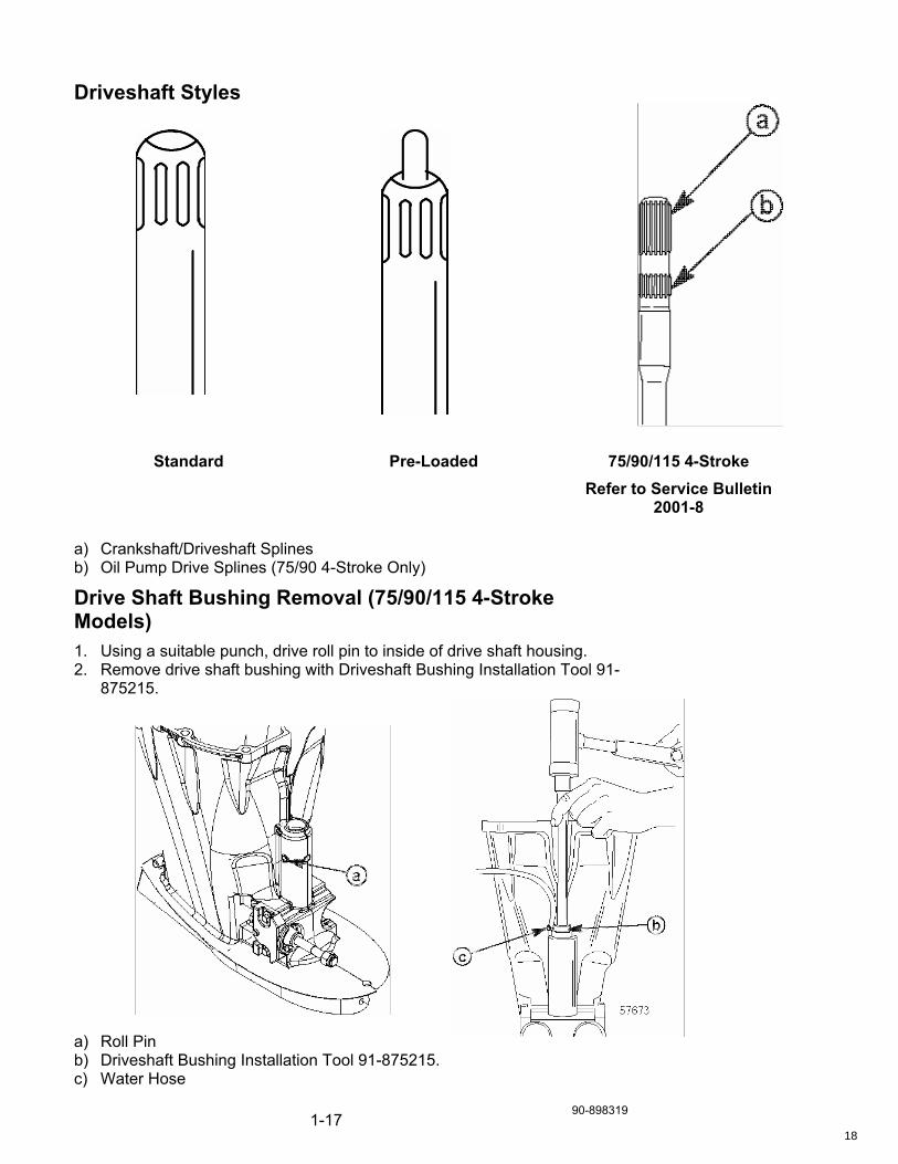
Driveshaft Styles
Standard Pre-Loaded 75/90/115 4-Stroke Refer to Service Bulletin
2001-8 a) Crankshaft/Driveshaft Splines b) Oil Pump Drive Splines (75/90 4-Stroke Only)
Drive Shaft Bushing Removal (75/90/115 4-Stroke Models) 1. Using a suitable punch, drive roll pin to inside of drive shaft housing. 2. Remove drive shaft bushing with Driveshaft Bushing Installation Tool 91-
875215. a) Roll Pin b) Driveshaft Bushing Installation Tool 91-875215. c) Water Hose
18

90-898319 1-18
Standard Driveshaft Bearing and Shim Position 1) Upper Driveshaft Bearing 2) Shim 1) Shim Position Pinion height is established for full tooth engagement and once set, is not changed. Driveshaft Bearing Preload Tool is used to apply upward pressure on Driveshaft Bearing for checking both pinion height and gear backlash.
Notes
__________________
__________________
__________________
__________________
__________________
__________________
__________________
__________________
__________________
__________________
__________________
__________________
__________________
__________________
__________________
__________________
__________________
__________________
__________________
__________________
__________________
__________________
__________________
__________________
__________________
__________________
19

1-19 90-898319
Preload Style Driveshaft Bearing and Shim Position 1) Upper Driveshaft Bearing 2) Shim 1) Shim Position Preload style driveshaft are loaded down by hand when checking pinion height and gear backlash.
Notes
__________________
__________________
__________________
__________________
__________________
__________________
__________________
__________________
__________________
__________________
__________________
__________________
__________________
__________________
__________________
__________________
__________________
__________________
__________________
__________________
__________________
__________________
__________________
__________________
__________________
__________________
20

90-898319 1-20
91-12349A2 Pinion Gear Locating Tool Instructions IMPORTANT: Forward gear assembly MUST BE installed in gear housing when checking pinion gear depth or an inaccurate measurement will be obtained.
Install Bearing Preload Tool (if required) on drive shaft following instructions in appropriate Service Manual.
Clean the gear housing bearing carrier shoulder and diameter.
Assemble tool as shown; DO NOT tighten collar retaining bolt at this time. a) Arbor b) Gauging Block; Install with numbers away from split collar c) Bolt; gauging block retainer d) Split Collar e) Bolt; Collar retaining f) Snap Ring Insert tool into forward gear assembly; position gauging block under pinion gear as shown. a) Gauging Block
Notes
__________________
__________________
__________________
__________________
__________________
__________________
__________________
__________________
__________________
__________________
__________________
__________________
__________________
__________________
__________________
__________________
__________________
__________________
__________________
__________________
__________________
__________________
__________________
__________________
__________________
__________________
21

1-21 90-898319
Remove tool, taking care not to change gauging block position, and tighten collar retaining bolt.
Insert tool into forward gear assembly; position proper numbered flat (from chart) of gauging block – under pinion gear.
Install proper locating disc against bearing carrier shoulder in gear housing.
Position access hole.
IMPORTANT: Pressure must be applied to drive shaft while checking clearance with feeler gauge. Apply pressure to drive shaft following instructions in appropriate Service Manual.
Determine pinion gear depth by inserting a feeler gauge thru access hole in locating disc.
The correct clearance between gauging block and pinion gear is .025 in. (0.64 mm). If clearance is incorrect, add (or subtract) shims from below the upper drive shaft bearing to raise (or lower) pinion gear.
IMPORTANT: On V-6 Outboards using 13/30 gear set, clearance between pinion gear and gauging block is .050 in. (1.27 mm). This is due to the smaller gear being manufactured from a smaller steel billet. a) Feeler Gauge b) Locating Tool c) Pinion
Notes
__________________
__________________
__________________
__________________
__________________
__________________
__________________
__________________
__________________
__________________
__________________
__________________
__________________
__________________
__________________
__________________
__________________
__________________
__________________
__________________
__________________
__________________
__________________
__________________
__________________
__________________
22

90-898319 1-22
Pinion Height Tool Instructions P/N 90-12555-1
Model
Gear Ratio (Pinion Gear
Teeth/Reverse Gear Teeth)
Use Flat No.
Use Disk No.
70 THRU 150 (IN-LINE)
OUTBOARDS
2.3:1 (13/30)
1.78:1 (14/25)
2.0:1 (14/28)
2.07:1 (14/29)
2.33:1 (12/28)
8
1
1
2
8
1
1
1
3
1
V-6 OUTBOARDS
2 Litre 2.4 Litre 2.5 Litre
2.3:1 (13/30)
2.3:1 (13/30)
1.78:1 (14/25)
2.0:1 (14/28)
1.87:1 (15/28)
6 1
7 2
1
7
7
2
2
1
2
2
V-6 OUTBOARD
3.0 Litre
1.62:1 (13/21)
1.64:1 (17/28)
1.75:1 (12/21)
1.87:1 (15/28)
4
4
4
4
2
2
2
2
V-6 OUTBOARD
3.4 Litre
1.64:1 (17/28) 4 2
1 Driveshaft WITH Pre-Load Pin 2 Driveshaft WITHOUT Pre-Load Pin
Notes
__________________
__________________
__________________
__________________
__________________
__________________
__________________
__________________
__________________
__________________
__________________
__________________
__________________
__________________
__________________
__________________
__________________
__________________
__________________
__________________
__________________
__________________
__________________
__________________
__________________
__________________
23

1-23 90-898319
Gear Position Correct Pinion Gear Height
Pinion Gear Height Too High
Notes
__________________
__________________
__________________
__________________
__________________
__________________
__________________
__________________
__________________
__________________
__________________
__________________
__________________
__________________
__________________
__________________
__________________
__________________
__________________
__________________
__________________
__________________
__________________
__________________
__________________
24

90-898319 1-24
Pinion Nut Installation Recess in nut is installed toward pinion gear.
After final adjustment to pinion height, and forward backlash has been established, apply Loctite 271 and torque new pinion nut to specified torque.
Backlash Flags Used on Current Mercury Outboards
91-19660--1 BACKLASH INDICATOR TOOL This flag has 4 numbers (1, 2, 3, & 4) and the part # is on it.
91-53459 BACKLASH INDICATOR TOOL This flag uses roman numerals for markings (I, II, III)
91-78473 BACKLASH INDICATOR TOOL This flag has numbers 1-4 on it and no part #
Notes
__________________
__________________
__________________
__________________
__________________
__________________
__________________
__________________
__________________
__________________
__________________
__________________
__________________
__________________
__________________
__________________
__________________
__________________
__________________
__________________
__________________
__________________
__________________
__________________
__________________
__________________
25

1-25 90-898319
V-6 135-250 HP Carb/EFI
BLOCK WATER PRESSURE AND SPEEDOMETER HOSE ROUTING a) Block Water Presasure b) Speedometer Pressure
Notes
__________________
__________________
__________________
__________________
__________________
__________________
__________________
__________________
__________________
__________________
__________________
__________________
__________________
__________________
__________________
__________________
__________________
__________________
__________________
__________________
__________________
__________________
__________________
__________________
__________________
__________________
26

90-898319 1-26
Speedometer Hose Junction a) Press In On Junction b) Pull Out on Hose
Speedometer Coupler Part Numbers 1) Coupler Fitting P/N 22-859448 2) Grommet P/N 25-821555 3) Adapter Fitting P/N 22-859731 4) Adapter Fitting P/N 22-859732 5) Coupler P/N 22-859747
Notes
__________________
__________________
__________________
__________________
__________________
__________________
__________________
__________________
__________________
__________________
__________________
__________________
__________________
__________________
__________________
__________________
__________________
__________________
__________________
__________________
__________________
__________________
__________________
__________________
__________________
__________________
27

1-27 90-898319
Gear Manufacturing Processes Mercury uses three different types of gears:
A Cut Gear. These can be either straight or spiral bevel. They start out from a piece of round bar stock or a forged blank. The teeth are then cut using a gear-generating machine.
A Near-Net Forged Gear. These can be straight gears, but are usually a spiral tooth. They are created from a forged blank that already has the shape of the teeth in the blank. Only a slight finish cut is then completed using the gear-generating machine.
A Finished Forged Gear. The finished forged gears used by Mercury are straight-tooth gears, as used in the Bravo 1 & 3 lower gearcase. These gears are used just as they are forged (except for machining the spline area).
The near-net and finished-forged gears provide a stronger gear. This is because the forging process causes the grain of the gear to form to the shape of the tooth as shown below.
CUT GEAR
NEAR NET & FINISHED FORGED
Notes
__________________
__________________
__________________
__________________
__________________
__________________
__________________
__________________
__________________
__________________
__________________
__________________
__________________
__________________
__________________
__________________
__________________
__________________
__________________
__________________
__________________
__________________
__________________
__________________
__________________
28

90-898319 2-1
Section 2
29
90-898319 2-2
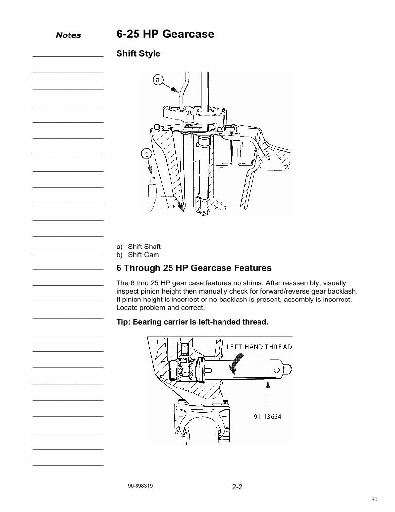
6-25 HP Gearcase Shift Style a) Shift Shaft b) Shift Cam
6 Through 25 HP Gearcase Features The 6 thru 25 HP gear case features no shims. After reassembly, visually inspect pinion height then manually check for forward/reverse gear backlash. If pinion height is incorrect or no backlash is present, assembly is incorrect. Locate problem and correct.
Tip: Bearing carrier is left-handed thread.
Notes
__________________
__________________
__________________
__________________
__________________
__________________
__________________
__________________
__________________
__________________
__________________
__________________
__________________
__________________
__________________
__________________
__________________
__________________
__________________
__________________
__________________
__________________
__________________
__________________
__________________
__________________
30

90-898319 3-1
Section 3 – 25-50 HP (Non - Bigfoot) Vertical Pull Gearcase
31

90-898319 3-2
25 Through 50 HP (Non - Bigfoot) Vertical Pull Gearcase Shift Style a) Shift Cam b) Cam Follower
25 thru 50 HP Non-Bigfoot Vertical Pull Gearcase Features The vertical pull gear case features no shims. This gear case is easily identified by the auxiliary water inlet located at the trim tab, underneath the anti-ventilation plate.
Tip: When it is necessary to rebuild this style of gearcase, review the service bulletins for information concerning gear ratio changes. A propeller change may be necessary.
Notes
__________________
__________________
__________________
__________________
__________________
__________________
__________________
__________________
__________________
__________________
__________________
__________________
__________________
__________________
__________________
__________________
__________________
__________________
__________________
__________________
__________________
__________________
__________________
__________________
__________________
__________________
32

90-898319 4-1
Section 4 - 50 and 60 HP (Non - Bigfoot) Cam and Follower
33

90-898319 4-2
50 and 60 HP (Non - Bigfoot) Cam and Follower Shift Style a) Cam b) Follower
Notes
__________________
__________________
__________________
__________________
__________________
__________________
__________________
__________________
__________________
__________________
__________________
__________________
__________________
__________________
__________________
__________________
__________________
__________________
__________________
__________________
__________________
__________________
__________________
__________________
__________________
__________________
34
90-898319 4-3
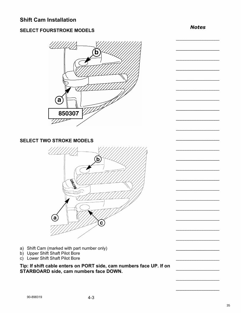
Shift Cam Installation
SELECT FOURSTROKE MODELS
SELECT TWO STROKE MODELS a) Shift Cam (marked with part number only) b) Upper Shift Shaft Pilot Bore c) Lower Shift Shaft Pilot Bore
Tip: If shift cable enters on PORT side, cam numbers face UP. If on STARBOARD side, cam numbers face DOWN.
Notes
__________________
__________________
__________________
__________________
__________________
__________________
__________________
__________________
__________________
__________________
__________________
__________________
__________________
__________________
__________________
__________________
__________________
__________________
__________________
__________________
__________________
__________________
__________________
__________________
__________________
__________________
35

5-1 90-898319
Section 5 – 75-125 HP Gearcase (Including 40-60 HP Bigfoot)

5-3 90-898319
Table of Contents Table of Contents..............................................................................................2 Table of Contents..............................................................................................3 75 Through 125 HP Gearcase Including 40-60 HP Bigfoot ..............................4
Description ....................................................................................................4 Cam Follower Components...........................................................................5 Shim Locations - 40 Bigfoot thru 125 HP ......................................................6 Pinion Height / Forward Gear Shimming.......................................................7 Pinion Height Shimming ................................................................................7 Forward Gear Backlash.................................................................................7 Gearcase Improvements ...............................................................................8
60 Bigfoot thru 125 Clutch/Gear Styles.............................................................9 3-Jaw vs 6-Jaw..............................................................................................9 6-Jaw Gearcase Changes...........................................................................10 Lower Shift Shaft Support ...........................................................................11 Shift Cam Installation 60 Bigfoot, 75-125/Bigfoot ........................................12 40/50 Bigfoot (4-Stroke) ..............................................................................13 Forward Gear Bearing Retainer ..................................................................14 Quiet Gears & Gear Ratio Change - Big Foot .............................................14 Lower Drive Shaft Bearing Race Tool Application Chart.............................15 Face Seal Installation ..................................................................................15 Desmodromic (EZ Shift) Gearcase..............................................................16 Adapter Plate (EZ Shift) ..............................................................................16 Shift Link Bracket (EZ Shift) ........................................................................16 Barrel Cup Retainer (EZ Shift).....................................................................17 Control Cable Latch (EZ Shift) ....................................................................17 Reverse Gear (EZ Shift) ..............................................................................17 Shift Shaft Bushing (EZ Shift)......................................................................18 Upper Shift Shaft Assembly (EZ Shift) ........................................................18 Shift Detent Assembly (EZ Shift) .................................................................18 Shift Cam (EZ Shift) ....................................................................................18 Cam Follower (EZ Shift) ..............................................................................19 Tiller Handle Kit - 75/90 & 115 EFI (4-Stroke) .............................................19

90-898319 5-4
75 Through 125 HP Gearcase Including 40-60 HP Bigfoot
Description This gear case is sometimes referred to as the “BIGFOOT” gear case when used on 40-60 HP engines. These combinations are used in applications where larger diameter propellers are necessary for improved boat handling. This gear case can also be termed the big bore 3 and 4 cylinder gear case.
Notes
__________________
__________________
__________________
__________________
__________________
__________________
__________________
__________________
__________________
__________________
__________________
__________________
__________________
__________________
__________________
__________________
__________________
__________________
__________________
__________________
__________________
__________________
__________________
__________________
__________________
__________________

5-5 90-898319
Cam Follower Components 1) Slide 2) Ball Bearings (Qty. 3) 3) Cam Follower 1) Propeller Shaft 2) Spring 3) Cross Pin 4) Slide 5) Ball Bearings (Qty. 3) 6) Cam Follower
Notes
__________________
__________________
__________________
__________________
__________________
__________________
__________________
__________________
__________________
__________________
__________________
__________________
__________________
__________________
__________________
__________________
__________________
__________________
__________________
__________________
__________________
__________________
__________________
__________________
__________________

90-898319 5-6
Shim Locations - 40 Bigfoot thru 125 HP 1) Pinion Height Shim Location 2) Forward Gear Shim Location
Notes
__________________
__________________
__________________
__________________
__________________
__________________
__________________
__________________
__________________
__________________
__________________
__________________
__________________
__________________
__________________
__________________
__________________
__________________
__________________
__________________
__________________
__________________
__________________
__________________
__________________
__________________
5-7 90-898319
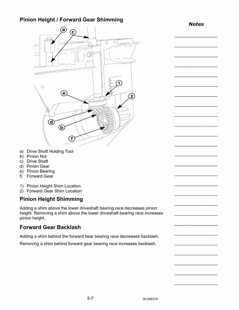
Pinion Height / Forward Gear Shimming a) Drive Shaft Holding Tool b) Pinion Nut c) Drive Shaft d) Pinion Gear e) Pinion Bearing f) Forward Gear 1) Pinion Height Shim Location 2) Forward Gear Shim Location
Pinion Height Shimming Adding a shim above the lower driveshaft bearing race decreases pinion height. Removing a shim above the lower driveshaft bearing race increases pinion height.
Forward Gear Backlash Adding a shim behind the forward bear bearing race decreases backlash.
Removing a shim behind forward gear bearing race increases backlash.
Notes
__________________
__________________
__________________
__________________
__________________
__________________
__________________
__________________
__________________
__________________
__________________
__________________
__________________
__________________
__________________
__________________
__________________
__________________
__________________
__________________
__________________
__________________
__________________
__________________
__________________
__________________

90-898319 5-8
Gearcase Improvements 75-125 (Bigfoot) gearcases have had many improvements made for durability reasons. To easily identify the newer gear case, refer to the following pictures. Once these were introduced, the gear case is now referred to as either a 3-Jaw or 6-Jaw reverse clutch. A complete 3 Jaw gear case is no longer available (NLA). When a complete gear case is needed, a 6-Jaw gear case is used as a replacement. NOTE: When replacing a 3-Jaw with a 6-Jaw gear case, the upper shift shaft must also be changed. The shaft is included with the gear case, but extra labor time will be necessary to remove the powerhead. Removal of the powerhead is required to install the upper shift shaft. Refer to Service Bulletin 96-17
Identify gear case design to ensure correct components are being installed. Design I – “3 Jaw Reverse Clutch” gear case identified with straight machined edge for trim tab screw mounting surface. Design II – “6 Jaw Reverse Clutch” gear case identified with angled machined edge for trim tab screw mounting surface. “3 Jaw Reverse Clutch” “6 Jaw Reverse Clutch” a) Design I – “3 Jaw Reverse Clutch” Gear Case Identifier b) Design II – “6 Jaw Reverse Clutch” Gear Case Identifier
NOTE: After the “6-Jaw Reverse Clutch” gear housing and updated Shift Shaft have been installed, replacement parts must be ordered from the “6-Jaw” section of a 1998 model year and newer parts list. “3-Jaw” and “6-Jaw” reverse clutch parts are NOT interchangeable.
Notes
__________________
__________________
__________________
__________________
__________________
__________________
__________________
__________________
__________________
__________________
__________________
__________________
__________________
__________________
__________________
__________________
__________________
__________________
__________________
__________________
__________________
__________________
__________________
__________________
__________________
__________________

5-9 90-898319
60 Bigfoot thru 125 Clutch/Gear Styles 3-Jaw vs 6-Jaw a) 3 Jaw Components b) 6 Jaw Components
Notes
__________________
__________________
__________________
__________________
__________________
__________________
__________________
__________________
__________________
__________________
__________________
__________________
__________________
__________________
__________________
__________________
__________________
__________________
__________________
__________________
__________________
__________________
__________________
__________________
__________________
__________________

90-898319 5-10
6-Jaw Gearcase Changes Some 1995, 1996 and 1997 model year engines have experienced low hour clutch failures. These failures are a result of the setup requirements. If adjusted incorrectly, the clutch may contact the forward gear at high idle, resulting in clutch and gear damage. You must remove all slack from the mechanism with a slight preload towards reverse when setting the shift on these engines. The redesigned lower unit desensitizes the adjustment procedure. The gears are further apart, allowing additional clutch movement on the propeller shaft. Required component changes are: 1. New clutch (6-Jaw reverse) 2. Shift cam (with larger neutral detent) 3. Follower (longer, with increased taper) 4. Propeller shaft (with longer clutch pin slot) 5. Cam follower spring (longer) 6. Cross pin retaining spring (heavier) 7. Reverse gear (6-Jaw) 8. Forward gear 9. Longer lower shift shaft (extends into casting below the shift cam) 10. Upper shift shaft link 11. Gear housing USA starting serial number 0G590000
Tip: 6-Jaw internal components and the older 3-Jaw components MUST NOT be interchanged. Machining differences exist in the internal components and gear housing.
When rebuilding and older 3-Jaw lower unit that has a “jumping out of gear” failure, the complete gear case must be replaced. Inspection has revealed that the jumping out of gear damages the shift shaft hole. The hole becomes oval and after the rebuild, the replacement gears and clutch will not hold engagement.
Notes
__________________
__________________
__________________
__________________
__________________
__________________
__________________
__________________
__________________
__________________
__________________
__________________
__________________
__________________
__________________
__________________
__________________
__________________
__________________
__________________
__________________
__________________
__________________
__________________
__________________
__________________
5-11 90-898319
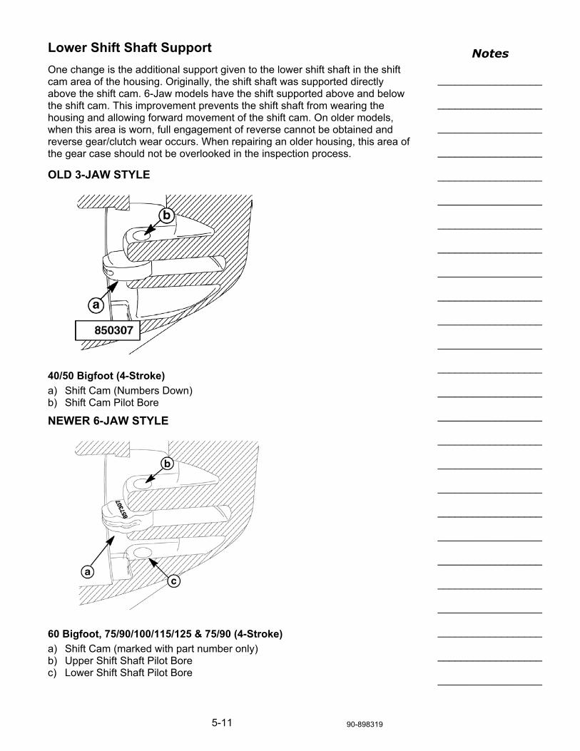
Lower Shift Shaft Support One change is the additional support given to the lower shift shaft in the shift cam area of the housing. Originally, the shift shaft was supported directly above the shift cam. 6-Jaw models have the shift supported above and below the shift cam. This improvement prevents the shift shaft from wearing the housing and allowing forward movement of the shift cam. On older models, when this area is worn, full engagement of reverse cannot be obtained and reverse gear/clutch wear occurs. When repairing an older housing, this area of the gear case should not be overlooked in the inspection process.
OLD 3-JAW STYLE 40/50 Bigfoot (4-Stroke) a) Shift Cam (Numbers Down) b) Shift Cam Pilot Bore
NEWER 6-JAW STYLE 60 Bigfoot, 75/90/100/115/125 & 75/90 (4-Stroke) a) Shift Cam (marked with part number only) b) Upper Shift Shaft Pilot Bore c) Lower Shift Shaft Pilot Bore
Notes
__________________
__________________
__________________
__________________
__________________
__________________
__________________
__________________
__________________
__________________
__________________
__________________
__________________
__________________
__________________
__________________
__________________
__________________
__________________
__________________
__________________
__________________
__________________
__________________
__________________
__________________

90-898319 5-12
Shift Cam Installation 60 Bigfoot, 75-125/Bigfoot
3-JAW STYLE 60 Bigfoot, 75/90/100/115/125 (2-Stroke) & 75/90 (4-Stroke) a) Shift Cam (marked with “UP” and part number only) b) Upper Shift Shaft Pilot Bore
NEWER 6-JAW STYLE 60 Bigfoot, 75/90/100/115/125 (2-Stroke) & 75/90 (4-Stroke) a) Shift Cam (marked with part number only) b) Upper Shift Shaft Pilot Bore c) Lower Shift Shaft Pilot Bore
Notes
__________________
__________________
__________________
__________________
__________________
__________________
__________________
__________________
__________________
__________________
__________________
__________________
__________________
__________________
__________________
__________________
__________________
__________________
__________________
__________________
__________________
__________________
__________________
__________________
__________________
__________________

5-13 90-898319
40/50 Bigfoot (4-Stroke) a) Shift Cam (Numbers Down) b) Shift Shaft Pilot Bore
Notes
__________________
__________________
__________________
__________________
__________________
__________________
__________________
__________________
__________________
__________________
__________________
__________________
__________________
__________________
__________________
__________________
__________________
__________________
__________________
__________________
__________________
__________________
__________________
__________________
__________________
__________________

90-898319 5-14
Forward Gear Bearing Retainer Additional groove and metal retainer 53-856823 was added to the forward gear to prevent the propeller shaft needle bearing from moving towards the rear of the gear. New service tool 91-877321A1 is required to set the needle bearing at 0.200 inch (5.08 mm) depth. a) Snap Ring When bearing moves towards the rear of the gear, shift effort is increased and unit may not have full shift engagement.
Quiet Gears & Gear Ratio Change - Big Foot A quiet gear design was introduced in 2003 MY. .The 75/90 has a gear ratio change to 2.33:1 (12/28) from 2.07:1 (14/29). Refer to Outboard Service Bulletin 2002-01 for introduction (propeller chart changes). There are also owners manual and service manual changes.
Decal Number Gear Teeth Pinion/Forward Gear Ratio
12 12/28 2.33:1
14 14/29 2.07:1
Notes
__________________
__________________
__________________
__________________
__________________
__________________
__________________
__________________
__________________
__________________
__________________
__________________
__________________
__________________
__________________
__________________

5-15 90-898319
Lower Drive Shaft Bearing Race Tool Application Chart
Gear Ratio Pinion Gear P/N (Teeth)
Pinion Gear P/N (Teeth)
Bearing Cup Driver
2.07:1 43-19672 (14) 91-13778T1 (No Stamp)
91-13780 (Stamped 91-13780)
2.07:1 43-881259 (14) 91-889622A01 (Stamped 91-889622)
91-889623 (Stamped 91-889623)
2.31:1 (13) 91-13778T1 (No Stamp)
91-13780 (Stamped 91-13780)
2.33:1 (12) 91-889622A01 (Stamped 91-889622)
91-889623 (Stamped 91-889623)
Face Seal Installation a) Face Seal Tool b) Face Seal
NOTE: If tool is not available, lightly press seal against housing until a height of 0.350 in. ± 0.030 in. (8.9mm _ 0.76mm) is obtained.

90-898319 5-16
Desmodromic (EZ Shift) Gearcase New gearcase shift design similar to small V6 to reduce shift loads. Requires new shift linkage adjustment. Requires installation manual (throttle cable) adjustment changes and service manual updating.
Adapter Plate (EZ Shift) P/N 888830C
Shift Link Bracket (EZ Shift) Shift Link Bracket p/n 888834A1 required for EZ Shift outboard is stamped to identify unique location for “115” throttle cable barrel cup retainer. The 75/90 (4-Stroke) models must be assembled with the throttle cable barrel cup retainer facing aft (no ID mark is provide).
Notes _______________________
_______________________
_______________________
_______________________
_______________________
_______________________
_______________________
_______________________
_______________________
_______________________
_______________________
_______________________
_______________________
_______________________
_______________________
_______________________
_______________________
_______________________
_______________________
_______________________
_______________________
_______________________
_______________________
_______________________
_______________________
_______________________
_______________________
_______________________

5-17 90-898319
Barrel Cup Retainer (EZ Shift) New cable retainer designed to eliminate excess clearance between retainer and retainer pocket of shift rail. Change reduces the amount of lost motion within the control cables which helps to reduce shift effort. Molding color changed form BLACK to WHITE (Natural) for ease of identification. Barrel Cup Retainer p/n 889530
Control Cable Latch (EZ Shift) New Throttle Cable Control Cable Latch p/n 889529 required for EZ Shift outboards. Latch is assembled either of two positions, one for the 75/90 (4-Stroke) and one for the 115 (4-Stroke) to correspond with the to the throttle cable barrel installation
Reverse Gear (EZ Shift) Clutch jaws for reverse gear utilize a 5º hook design which is required to hold clutch into reverse gear on outboards with EZ Shift systems. Previous design was a 5º push out design.
Model (Ratio) Previous Part New Part (EZ Shift) 75/90 (2.33:1) T28 43-882814T 43-889990T
115 EFI (2.07:1) T29 43-850036T 43-889991T Note: Reverse gears previous/new DO NOT interchange.
Notes _______________________
_______________________
_______________________
_______________________
_______________________
_______________________
_______________________
_______________________
_______________________
_______________________
_______________________
_______________________
_______________________
_______________________
_______________________
_______________________
_______________________
_______________________
_______________________
_______________________
_______________________
_______________________
_______________________
_______________________
_______________________
_______________________
_______________________
_______________________

90-898319 5-18
Shift Shaft Bushing (EZ Shift) New Shift Shaft Bushing required to guide the upper and lower shift shafts together when installing lower unit onto driveshaft housing. p/n 23-891637
Upper Shift Shaft Assembly (EZ Shift) New Upper Shift Shaft Assembly p/n 888835A1 required for EZ Shift Outboards. Top end of shift shaft provides cam for shift detent as well and neutral switch for 115 EFI.
Shift Detent Assembly (EZ Shift) New Shift Detent Assembly p/n 88823001 required for EZ Shift outboards. Detent provides positive feel of gear position.
Shift Cam (EZ Shift) New shift cam p/n 77172 required for EZ Shift outboards. Five digit part number utilized due the lack of available room for a part number stamp on the cam.
Notes _______________________
_______________________
_______________________
_______________________
_______________________
_______________________
_______________________
_______________________
_______________________
_______________________
_______________________
_______________________
_______________________
_______________________
_______________________
_______________________
_______________________
_______________________
_______________________
_______________________
_______________________
_______________________
_______________________
_______________________
_______________________
_______________________
_______________________
_______________________

5-19 90-898319
Cam Follower (EZ Shift) New Cam Follower p/n 888807 required for EZ Shift outboards.
Tiller Handle Kit - 75/90 & 115 EFI (4-Stroke) A new tiller handle kit will be required for the 75/90 & 115 EFI (4-Stroke) model for 2004 because of the EZ Shift.
Notes _______________________
_______________________
_______________________
_______________________
_______________________
_______________________
_______________________
_______________________
_______________________
_______________________
_______________________
_______________________
_______________________
_______________________
_______________________
_______________________
_______________________
_______________________
_______________________
_______________________
_______________________
_______________________
_______________________
_______________________
_______________________
_______________________
_______________________
_______________________

6-1 90-898319
Section 6 - 2.0L, 2.4L and 2.5L V-6 EZ Shift

90-898319 6-4
2.0L, 2.4L and 2.5L V-6 EZ Shift a) Cam Follower b) Shift Cam
Notes
__________________
__________________
__________________
__________________
__________________
__________________
__________________
__________________
__________________
__________________
__________________
__________________
__________________
__________________
__________________
__________________
__________________
__________________
__________________
__________________
__________________
__________________
__________________
__________________
__________________
__________________

6-5 90-898319
Shim Locations
STANDARD ROTATION
V-6 COUNTER ROTATION 1) Pinion Height 2) Forward Gear
Notes
__________________
__________________
__________________
__________________
__________________
__________________
__________________
__________________
__________________
__________________
__________________
__________________
__________________
__________________
__________________
__________________
__________________
__________________
__________________
__________________
__________________
__________________
__________________
__________________
__________________
__________________

90-898319 6-6
Pinion Height Shimming 1) Pinion Height Shims • Adding a shim at the upper driveshaft bearing race will increase pinion
height.
• Removing a shim at the upper driveshaft bearing race will decrease pinion height.
Notes
__________________
__________________
__________________
__________________
__________________
__________________
__________________
__________________
__________________
__________________
__________________
__________________
__________________
__________________
__________________
__________________
__________________
__________________
__________________
__________________
__________________
__________________
__________________
__________________
__________________
__________________

6-7 90-898319
Standard Rotation Backlash 1) Gear Shim Location 2) Gear Shim Location
FORWARD GEAR BACKLASH (#1)
• Adding a shim at the forward gear bearing race will decrease forward gear backlash.
• Removing a shim at the forward gear bearing race will increase forward gear backlash.
REVERSE GEAR BACKLASH (#2)
• If reverse gear backlash is incorrect, gear case is assembled incorrectly or parts are worn.
Counter-Rotation Backlash • The gear positions in a counter-rotation gear case are reversed. Reverse
gear is located closest to the leading edge and forward gear is located closest to the propeller.
FORWARD GEAR BACKLASH (#2)
• Adding a shim at the forward gear bearing race will increase forward gear backlash.
• Removing a shim at the forward gear bearing race will decrease forward gear backlash.
REVERSE GEAR BACKLASH (#1)
• Adding a shim at the shoulder in the gear case will decrease reverse gear backlash.
• Removing a shim at the shoulder in the gear case will increase reverse gear backlash.
Notes
__________________
__________________
__________________
__________________
__________________
__________________
__________________
__________________
__________________
__________________
__________________
__________________
__________________
__________________
__________________
__________________
__________________
__________________
__________________
__________________
__________________
__________________
__________________
__________________
__________________
__________________

6-9 90-898319
Clutch Actuator Rod Change – 1991 135 thru 275
MARINER AND MERCURY
135 thru 200 - S/N 0D044293 and above
275 - S/N 0D038988 and above
The clutch actuator rod has changed and the forward spring and washer are not required on the right hand rotation lower units. Counter rotation lower units continue to use the clutch actuator rod with the two springs and washers. With the single spring system, shimming the spring to center the clutch cross pin is not required.
CLUTCH ACTUATOR ROD
Previous 2 Springs New 1 Spring
135-200 P/N 79911 P/N 816520
275 P/N 88523 P/N 816519
PREVIOUS RIGHT HAND ROTATION ROD ASSEMBLY a) Springs b) Clutch Actuator Rod c) Washers d) Clutch Cross Pin e) Retaining Pin
NEW RIGHT HAND ROTATION ROD ASSEMBLY a) Springs b) Clutch Actuator Rod c) Washers d) Clutch Cross Pin e) Retaining Pin
Notes
__________________
__________________
__________________
__________________
__________________
__________________
__________________
__________________
__________________
__________________
__________________
__________________
__________________
__________________
__________________
__________________
__________________
__________________
__________________
__________________
__________________
__________________
__________________
__________________
__________________
__________________

90-898319 6-10
MEASURING ROD ASSEMBLY a) Spring Locating Pin b) Shim Washer c) Compression Spring d) Elongated Slot e) Cross Pin Tool (91-86642) f) Clutch Actuator Rod g) Shim Washer Must Lie Flat on Spring Locating Pin
Notes
__________________
__________________
__________________
__________________
__________________
__________________
__________________
__________________
__________________
__________________
__________________
__________________
__________________
__________________
__________________
__________________
__________________
__________________
__________________
__________________
__________________
__________________
__________________
__________________
__________________
__________________

6-11 90-898319
Gearcase Oil Slinger Eliminated - 1992 135 thru 200
MARINER AND MERCURY
1992 and newer
135 thru 200
S/N 0D154836 and above
Service Replacement Gearcase produced after 2/18/92
The gear case oil slinger p/n 23–43998 is not installed in the gear case on the models listed. This change was made in conjunction with enlargement of the oil circulation hole from 1/4 inch (6.3 mm) diameter to 3/8 inch (9.5 mm) diameter. The enlargement of the oil circulation hole was made prior to removing the oil slinger to eliminate any assembly error. a) Oil Slinger Gearcases with a 1/4 inch (6.3 mm) oil circulation hole must have the oil slinger installed.
IMPORTANT: Gearcases with the 1/4 inch (6.3 mm) diameter oil circulation hole REQUIRE the oil slinger (P/N 23–43998) to provide lubrication to the upper bearing.
Gearcases with a 3/8 inch (9.5 mm) oil circulation hole may or may not have the oil slinger installed without any adverse affect.
The oil circulation hole connects the torpedo area to the upper drive shaft bearing area.
135 thru 200 Gearcase a) Oil Circulation Hole
Notes
__________________
__________________
__________________
__________________
__________________
__________________
__________________
__________________
__________________
__________________
__________________
__________________
__________________
__________________
__________________
__________________
__________________
__________________
__________________
__________________
__________________
__________________
__________________
__________________
__________________
__________________

90-898319 6-12
Top View of the Gearcase a) Oil Circulation Hole
Rear View of the Gearcase a) Oil Circulation Hole
Notes
__________________
__________________
__________________
__________________
__________________
__________________
__________________
__________________
__________________
__________________
__________________
__________________
__________________
__________________
__________________
__________________
__________________
__________________
__________________
__________________
__________________
__________________
__________________
__________________
__________________
__________________

6-13 90-898319
Non-Ratcheting Gear Case Changes
1997 CHANGE
Clutch actuator rod – no longer machined for compression springs compression spring(s) – removed from actuator rod, no longer required
Cross pin changed – old pin had two flat sides, new pin is round. The flat sides are not required because the compression springs have been removed.
One of the two detent pins has been removed and the pin which remains no longer has a hole in the back side of the pin.
Cross and detent pin retainer spring changed from two springs to one spring. The single spring no longer has the bent tab, which on older units, engaged the hole on the detent pin. S/N 0G438000
Tip: When running non-ratcheting gearcase on a dyno, use ratchet strap to load the dyno head to gearcase to maintain a load on the forward gear tapered bearing.
Shift Cam
1997 CHANGE
A revised shift cam is used on 1997 models, this cam has a raised boss added to the top. This boss prevents the cam from moving up inside the gear case during operation. If the cam moves up on the shift shaft, the cam could contact the gear housing. The cam contact would limit the amount of clutch travel and, in turn, lower clutch and gear ”jaw” life. The new cam can be identified by a casting number of 78956–2 and will back fit older units. S/N 0G438000
Notes
__________________
__________________
__________________
__________________
__________________
__________________
__________________
__________________
__________________
__________________
__________________
__________________
__________________
__________________
__________________
__________________
__________________
__________________
__________________
__________________
__________________
__________________
__________________
__________________
__________________
__________________

90-898319 6-14
Forward Gear Bearing Retainer a) Snap Ring Additional groove and metal retainer (53-856823) was added to the forward gear to prevent the propeller shaft needle bearing from moving towards the rear of the gear. When the bearing moves towards the rear of the gear, shift effort is increased and unit may not have full shift engagement. New service tool 91-877321A1 is required to set the needle bearing at 0.200 inch (5.08 mm) depth.
Notes
__________________
__________________
__________________
__________________
__________________
__________________
__________________
__________________
__________________
__________________
__________________
__________________
__________________
__________________
__________________
__________________
__________________
__________________
__________________
__________________
__________________
__________________
__________________
__________________
__________________
__________________

6-15 90-898319
Lower Driveshaft Bearing 2.0L, 2.4L, 2.5L and 3.0L Gear Housings When removing the lower driveshaft bearing from the gear housing, all needle bearing rollers should be inside the bearing cage so the bearing can be successfully removed from the housing without breaking the bearing cage. Once removed, this bearing is to be replaced. When reinstalling the bearing, look for the marking “This End Up” or “numbers” on one side of the bearing race. The bearing is .005” larger on the lettered side. This large side is installed first to help retain the bearing in the gear housing. If the bearing is installed upside down, the bearing will “walk” down to the top of the pinion gear and cause a failure.
NOTE: If the pinion bearing needle bearings have fallen out , install 18 needles into needle bearing outer race. Use 2-4-C w/Teflon (92-825407A12), to help hold needles in place.
a) Rollers (18) b) Roller Bearing Outer Race c) 2-4-C w/Teflon (92-825407A12)
Tip: Special Tool 91-61067A3 (Pinion Nut Adapter) can be used to remove pinion nut if driveshaft is broken at pinion bearing area.
Notes
__________________
__________________
__________________
__________________
__________________
__________________
__________________
__________________
__________________
__________________
__________________
__________________
__________________
__________________
__________________
__________________
__________________
__________________
__________________
__________________
__________________
__________________
__________________
__________________
__________________
__________________
90-898319 7-1
Section 7 - V-6 XR4, XR6, Mag II, Mag III

90-898319 7-3
Table of Contents Table of Contents..............................................................................................3 V-6 XR4, XR6, Mag II, Mag III ..........................................................................4
Early Model ...................................................................................................4 Later Model ...................................................................................................4 Pinion Height Shimming ................................................................................5 Standard Rotation Backlash..........................................................................6 Gear Housing (Driveshaft) - XR6/Magnum III - 1.78:1 Ratio .........................7 Gear Housing (Prop Shaft) - XR6/Magnum III - 1.78:1 Ratio ........................8 Notes on 4 1/4” Torpedo Bore V-6 Gearcase................................................9 Driveshaft Needle Bearing ............................................................................9 Clutch Modifications ....................................................................................10

90-898319 7-4
V-6 XR4, XR6, Mag II, Mag III Early Model
Later Model
Notes
__________________
__________________
__________________
__________________
__________________
__________________
__________________
__________________
__________________
__________________
__________________
__________________
__________________
__________________
__________________
__________________
__________________
__________________
__________________
__________________
__________________
__________________
__________________
__________________
__________________
__________________

90-898319 7-5
Pinion Height Shimming 1) Pinion Height Shims • Adding a shim at the upper driveshaft bearing race will increase pinion
height.
• Removing a shim at the upper driveshaft bearing race will decrease pinion height.
Notes
__________________
__________________
__________________
__________________
__________________
__________________
__________________
__________________
__________________
__________________
__________________
__________________
__________________
__________________
__________________
__________________
__________________
__________________
__________________
__________________
__________________
__________________
__________________
__________________
__________________
__________________

90-898319 7-6
Standard Rotation Backlash 1) Forward Gear Shim Location
FORWARD GEAR BACKLASH (#1)
• Adding a shim at the forward gear bearing race will decrease forward gear backlash.
• Removing a shim at the forward gear bearing race will increase forward gear backlash.
REVERSE GEAR BACKLASH
NOTE: Reverse gear is not adjustable. However, reverse gear backlash which should be 0.030” - 0.048” (0.76mm - 1.21 mm) can be measured to determine proper assembly of gear case. If reverse gear backlash is not within specified tolerance, then gear case is not properly assembled or parts are excessively worn.
Notes
__________________
__________________
__________________
__________________
__________________
__________________
__________________
__________________
__________________
__________________
__________________
__________________
__________________
__________________
__________________
__________________
__________________
__________________
__________________
__________________
__________________
__________________
__________________
__________________
__________________
__________________

90-898319 7-7
Gear Housing (Driveshaft) - XR6/Magnum III - 1.78:1 Ratio

90-898319 7-8
Gear Housing (Prop Shaft) - XR6/Magnum III - 1.78:1 Ratio

90-898319 7-9
Notes on 4 1/4” Torpedo Bore V-6 Gearcase Starting in 1988 thru the mid 90’s, XR4, XR6, Mag II’s and Mag III’s were available with a gear case that measures 4 1/4” across the torpedo bore. This case is commonly referred to a “small bore” or “small tube” gear case when talking about V-6 housings. The standard V-6 gear case has always used a 4 3/4” torpedo bore gear housing. The smaller gear case was used on the XR series and the Magnum series engines in order to improve performance. In some applications, the housings actually were too small for the boats that the engines were installed on. Heavier bass boats needed the larger gear case so the larger diameter propellers could be used. This was necessary so the boats would “lift” and better top speeds could be achieved. The gear ratio of the 4 1/4” unit is 1.78:1. This unit is interchangeable with the 4 3/4” unit but be aware of the slight gear ratio change to a 1.87:1. When the larger unit is installed in place of the smaller unit, the propeller shaft will be deeper in the water by approximately 1” so engine height may have to be adjusted.
To determine what size gear case one is working with, measure across the bore of the housing at the cover nut location. See illustration below.
4-1/4 Inch 4-3/4 Inch
Driveshaft Needle Bearing
NOTE: Two different sized driveshaft needle bearings may be found in XR6 and MAGNUM III gearcases. Externally, these gearcases may be identified by appearance, as follows:
EARLY MODEL
Notes
__________________
__________________
__________________
__________________
__________________
__________________
__________________
__________________
__________________
__________________
__________________
__________________
__________________
__________________
__________________
__________________
__________________
__________________
__________________
__________________
__________________
__________________
__________________
__________________
__________________
__________________

90-898319 7-10
LATE MODEL After identity of gear case has been established, refer to the appropriate driveshaft needle bearing removal and installation procedure.
Clutch Modifications a) Relief at Base of Clutch Dog
Notes
__________________
__________________
__________________
__________________
__________________
__________________
__________________
__________________
__________________
__________________
__________________
__________________
__________________
__________________
__________________
__________________
__________________
__________________
__________________
__________________
__________________
__________________
__________________
__________________
__________________
__________________
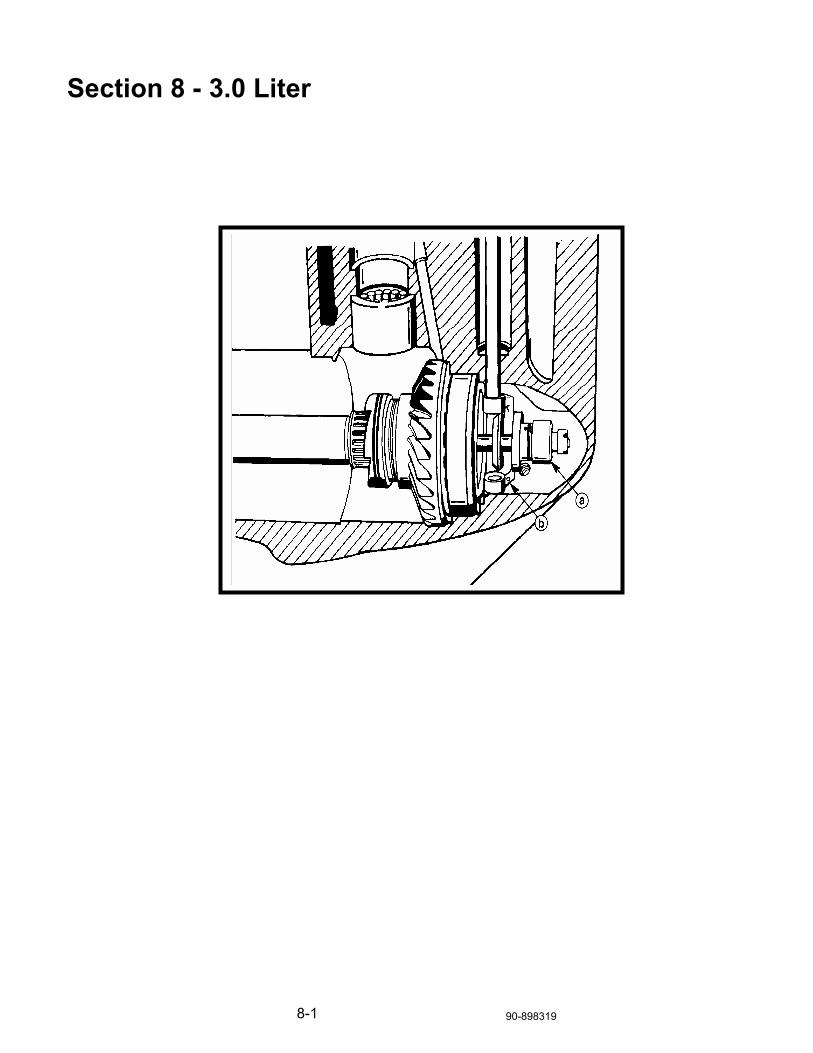
8-1 90-898319
Section 8 - 3.0 Liter

8-3 90-898319
Table of Contents Table of Contents..............................................................................................2 Table of Contents..............................................................................................3 3.0 Liter .............................................................................................................4
Spool Shift .....................................................................................................4 Pinion Height Shimming ................................................................................5 Standard Rotation Backlash..........................................................................6 Counter-Rotation Backlash ...........................................................................6 Shift Spool Identification................................................................................7 Shift Spool Identification................................................................................8 Spool Adjustment ..........................................................................................9
All 3.0 Litre Product.........................................................................................10 Gear Case Change .....................................................................................10 Water Tube..................................................................................................10 Forward Gear Bearing Retainer ..................................................................12 Propeller Shaft and Reverse Thrust Washer Inspection .............................12 3.0L Dual Upper Driveshaft Bearing............................................................13 Drive Shaft Seal Carrier ..............................................................................14

90-898319 8-4
3.0 Liter Spool Shift a) Shift Spool b) Shift Crank
Notes
__________________
__________________
__________________
__________________
__________________
__________________
__________________
__________________
__________________
__________________
__________________
__________________
__________________
__________________
__________________
__________________
__________________
__________________
__________________
__________________
__________________
__________________
__________________
__________________
__________________
__________________

8-5 90-898319
Pinion Height Shimming 1) Pinion Height Shims • Adding a shim at the upper driveshaft bearing race will increase pinion
height.
• Removing a shim at the upper driveshaft bearing race will decrease pinion height.
Notes
__________________
__________________
__________________
__________________
__________________
__________________
__________________
__________________
__________________
__________________
__________________
__________________
__________________
__________________
__________________
__________________
__________________
__________________
__________________
__________________
__________________
__________________
__________________
__________________
__________________
__________________

90-898319 8-6
Standard Rotation Backlash 1) Gear Shim Location 2) Gear Shim Location
FORWARD GEAR BACKLASH (#1)
• Adding a shim at the forward gear bearing race will decrease forward gear backlash.
• Removing a shim at the forward gear bearing race will increase forward gear backlash.
REVERSE GEAR BACKLASH (#2)
• If reverse gear backlash is incorrect, gear case is assembled incorrectly or parts are worn.
Counter-Rotation Backlash • The gear positions in a counter-rotation gear case are reversed. Reverse
gear is located closest to the leading edge and forward gear is located closest to the propeller.
FORWARD GEAR BACKLASH (#2)
• Adding a shim at the forward gear bearing race will increase forward gear backlash.
• Removing a shim at the forward gear bearing race will decrease forward gear backlash.
REVERSE GEAR BACKLASH (#1)
• Adding a shim at the shoulder in the gear case will decrease reverse gear backlash.
• Removing a shim at the shoulder in the gear case will increase reverse gear backlash.
Notes
__________________
__________________
__________________
__________________
__________________
__________________
__________________
__________________
__________________
__________________
__________________
__________________
__________________
__________________
__________________
__________________
__________________
__________________
__________________
__________________
__________________
__________________
__________________
__________________
__________________
__________________
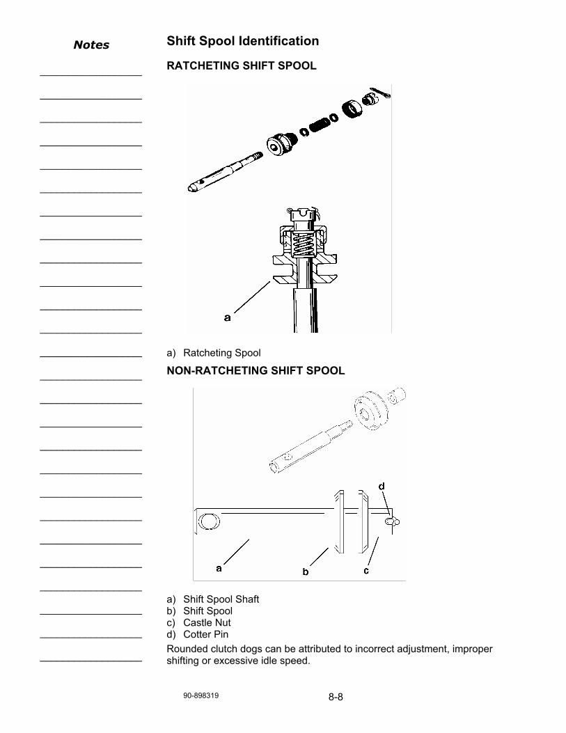
90-898319 8-8
Shift Spool Identification
RATCHETING SHIFT SPOOL a) Ratcheting Spool
NON-RATCHETING SHIFT SPOOL a) Shift Spool Shaft b) Shift Spool c) Castle Nut d) Cotter Pin Rounded clutch dogs can be attributed to incorrect adjustment, improper shifting or excessive idle speed.
Notes
__________________
__________________
__________________
__________________
__________________
__________________
__________________
__________________
__________________
__________________
__________________
__________________
__________________
__________________
__________________
__________________
__________________
__________________
__________________
__________________
__________________
__________________
__________________
__________________
__________________
__________________

8-9 90-898319
Spool Adjustment Inspect to insure that the spool has no more than 0.002-0.010 (0.05-0.25 mm) end play. a) Ratcheting Type Spool b) Non-Ratcheting Type Spool
If this adjustment did not produce the desired results it will be necessary to disassemble, clean, and reassemble the shift spool assembly. If the spool assembly has been already disassembled and cleaned it will be necessary to replace the shift spool assembly.
Notes
__________________
__________________
__________________
__________________
__________________
__________________
__________________
__________________
__________________
__________________
__________________
__________________
__________________
__________________
__________________
__________________
__________________
__________________
__________________
__________________
__________________
__________________
__________________
__________________
__________________
__________________

90-898319 8-10
All 3.0 Litre Product Gear Case Change The gear case changed from 10 water pick–up holes to 16 water pick–up holes. This provides increased water pressure/flow into the cooling system. The new gear housing will back fit as a complete lower unit, however the original water tube coupler must be used. The water tube coupler supplied with the replacement lower unit is for the 1” water tube and will not seal the 3/4” tube used on the older engines. The gear housing can be used to repair older engines if the following parts are used: Standard rotation - the large bearing on the forward gear must be changed.
Counter rotation - the reverse gear bearing adaptor must be changed if the old gear housing has a casting number 1623-822442C2
Refer to Quicksilver Parts Bulletin 96-2
Water Tube
1997 CHANGE
To allow this increased pressure/flow from the 16 hole gear case into the powerhead the water tube diameter increased from 3/4” to 1” along with the necessary seals and castings. This will improve water flow and decrease water tube erosion.
Notes
__________________
__________________
__________________
__________________
__________________
__________________
__________________
__________________
__________________
__________________
__________________
__________________
__________________
__________________
__________________
__________________
__________________
__________________
__________________
__________________
__________________
__________________
__________________
__________________
__________________

8-11 90-898319
2000 MODEL YEAR
• The following improvements were made to increase durability, and improve water flow to the engines. Some were running changes to the 1999 model. The lower unit complete, will back fit to any prior models that use the 13 spline drive shaft.
• NEW CLUTCH MATERIAL : New clutch material to increase clutch life. Starting S/N 0G839627, box date September, ’98.
• PROPELLER SHAFT: Propeller shaft surface finish at thrust washer taper improved. 2000 Model year
• DRIVESHAFT SEAL CARRIER: Changed to a one piece driveshaft seal carrier. This eliminated a glue joint and a location for a possible water leak. Starting S/N 0G886033.
• MOUNTING STUD: The rear mounting stud was changed from 10 mm to 12mm. Increased durability of driveshaft housing to gear housing joint. Starting S/N 0G899340.
• PINION GEAR: Pinion gear now has full radius splines. Increases spline durability. 2000 model year.
• GEARS: Gear have changed to a near net forging, new style cutters are being used to machine the gears and shot peening process changed, all to increase gear life. 2000 model year .
• REVERSE GEAR: Reverse gear tooth length change to increases gear life. 2000 model year.
• HEAT TREAT: Gear heat treat changed to increase gear life. 2000 model year start.
• CLUTCH SPLINES: Full internal splines on clutch to increases clutch life. 2000 model year start.
• CLUTCH RADIUS: Added .060 in. radius to clutch teeth. Larger radius at root will make a stronger tooth. 2000 model year start.
• DRIVESHAFT: Single piece driveshaft for both production and service replacements to reduce driveshaft whip and increase driveshaft durability. 2000 Model year start.
• DRAIN/FILL PLUGS: Magnet removed from drain plug, and improved plug seals to drain and fill plug. 2000 model year start.
• DRIVESHAFT BEARINGS: Dual upper driveshaft bearings to reduce driveshaft whip and prevent driveshaft from dropping down at idle speed. Increase driveshaft and gear life, and reduces water intrusion. 2000 model year start.
• WATER PICKUPS: Lower unit will now have front nose water pickups, in addition to the standard side water pickups. Improves water flow to engine. 2000 model year start.
Notes
__________________
__________________
__________________
__________________
__________________
__________________
__________________
__________________
__________________
__________________
__________________
__________________
__________________
__________________
__________________
__________________
__________________
__________________
__________________
__________________
__________________
__________________
__________________
__________________
__________________

90-898319 8-12
Forward Gear Bearing Retainer Additional groove and metal retainer (53-856823) was added to the forward gear to prevent the propeller shaft needle bearing from moving towards the rear of the gear. When bearing moves towards the rear of the gear, shift effort is increased and unit may not have full shift engagement. New service tool 91-877321A1 is required to set the needle bearing at 0.200 inch (5.08 mm) depth. a) Snap Ring When bearing moves towards the rear of the gear, shift effort is increased and unit may not have full shift engagement.
Propeller Shaft and Reverse Thrust Washer Inspection Measure propeller shaft FORWARD to REVERSE shoulder length. If measurement is under 2.040 in. (51.82mm), replace propeller shaft. Inspect REVERSE thrust washer for wear or taper. Measure thickness of washer. If thickness is LESS than 0.240 in. (6.1mm), replace washer.
Notes
__________________
__________________
__________________
__________________
__________________
__________________
__________________
__________________
__________________
__________________
__________________
__________________
__________________
__________________
__________________
__________________
__________________
__________________
__________________
__________________
__________________
__________________
__________________
__________________
__________________

8-13 90-898319
3.0L Dual Upper Driveshaft Bearing a) Driveshaft Housing b) Lower driveshaft Bearing Cup c) Location of Driveshaft End Play Shims a) Driveshaft Holding Tool b) Breaker Bar c) Socket Later model 3.0L engines use a dual bearing arrangement on the driveshaft. The housing that utilizes the dual bearings can be used with the older driveshaft with a single bearing. The lower bearing is deleted if this combination is used.
Notes
__________________
__________________
__________________
__________________
__________________
__________________
__________________
__________________
__________________
__________________
__________________
__________________
__________________
__________________
__________________
__________________
__________________
__________________
__________________
__________________
__________________
__________________
__________________
__________________
__________________

90-898319 8-14
Drive Shaft Seal Carrier • 3.0 Liter Opti/EFI
• Orange coating on carrier O-ring flaking off, replaced with black O-ring.
• Carrier changed to Yellow for contrast between carrier & O-ring.
Notes
_________________________________________________________________________________
_________________________________________________________________________________
_________________________________________________________________________________
_________________________________________________________________________________
_________________________________________________________________________________
_________________________________________________________________________________
_________________________________________________________________________________
_________________________________________________________________________________
_________________________________________________________________________________
_________________________________________________________________________________
_________________________________________________________________________________
_________________________________________________________________________________

9-1 90-898319
Section 9 - 225 EFI FourStroke
90-898319 9-2
Table of Contents Table of Contents .............................................................................................2 225 EFI FourStroke - Shimming Standard Rotation Gearcase.........................3
Selecting the Pinion Shims ...........................................................................3 Selecting the Forward Gear Shims ...............................................................5 Selecting the Reverse Gear Shims ...............................................................7 Measuring Backlash......................................................................................9
225 EFI FourStroke - Shimming Counter Rotation Gearcase ........................11 Selecting the Pinion Shims .........................................................................11 Selecting the Reverse Gear Shims .............................................................13 Selecting the Forward Gear Shims .............................................................15 Selecting Propeller Shaft Shims..................................................................17 Measuring Backlash....................................................................................18

9-3 90-898319
225 EFI FourStroke - Shimming Standard Rotation Gearcase Selecting the Pinion Shims
FORMULA
(T3) = 82.0 + P/100 – M3 – M4
T3 – SHIM THICKNESS
M4 – DISTANCE BETWEEN SHIMMING TOOL AND PINION a) Calipers
Notes _______________________
_______________________
_______________________
_______________________
_______________________
_______________________
_______________________
_______________________
_______________________
_______________________
_______________________
_______________________
_______________________
_______________________
_______________________
_______________________
_______________________
_______________________
_______________________
_______________________
_______________________
_______________________
_______________________
_______________________
_______________________
_______________________
_______________________
_______________________

90-898319 9-4
M3 – DRIVE SHAFT BEARING CARRIER MEASUREMENT a) Calipers
“P” MARK – GEAR HOUSING DIMENSION DEVIATION FROM STANDARD
T3 RESULTS – ROUNDING TABLE
Calculated Numeral at 1/100 Place Rounded Numeral
1, 2 0
3, 4, 5 2
6, 7, 8 5
9, 10 8
LAB EXCERCISE
ACTUAL
T3 = 82.0 + P/100 - M3 - M4
_______ = 82.0 + _____/100= ______ _____ _____
Notes _______________________
_______________________
_______________________
_______________________
_______________________
_______________________
_______________________
_______________________
_______________________
_______________________
_______________________
_______________________
_______________________
_______________________
_______________________
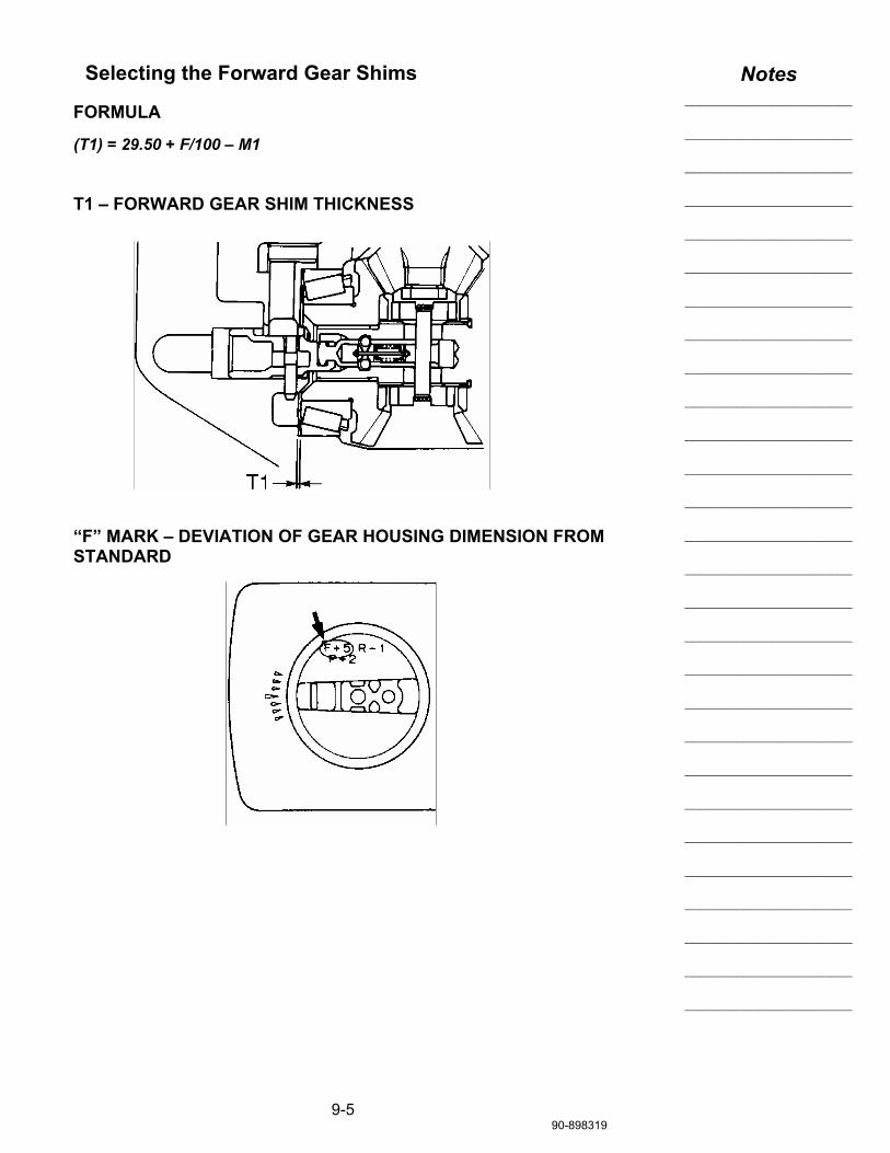
9-5 90-898319
Selecting the Forward Gear Shims
FORMULA
(T1) = 29.50 + F/100 – M1
T1 – FORWARD GEAR SHIM THICKNESS
“F” MARK – DEVIATION OF GEAR HOUSING DIMENSION FROM STANDARD
Notes _______________________
_______________________
_______________________
_______________________
_______________________
_______________________
_______________________
_______________________
_______________________
_______________________
_______________________
_______________________
_______________________
_______________________
_______________________
_______________________
_______________________
_______________________
_______________________
_______________________
_______________________
_______________________
_______________________
_______________________
_______________________
_______________________
_______________________
_______________________

90-898319 9-6
M1 – FORWARD GEAR BEARING HEIGHT a) Forward Gear Tapered Roller Bearing b) Caliper c) Shimming Plate (91-889586) d) Forward Gear Taperd Roller Bearing Race
T1 RESULTS – ROUNDING TABLE
Calculated Numeral at 1/100 Place Rounded Numeral
1, 2 0
3, 4, 5 2
6, 7, 8 5
9, 10 8
LAB EXCERCISE
ACTUAL
T1 = 29.5 + F/100 - M1
_______ = 29.5 + _____/100= ______ _____

9-7 90-898319
Selecting the Reverse Gear Shims
FORMULA
(T2) = 21.0 + R/100 – A/100 – M2
T2 - REVERSE GEAR SHIM THICKNESS
“R” MARK – GEAR HOUSING DIMENSION DEVIATION FROM STANDARD
Notes _______________________
_______________________
_______________________
_______________________
_______________________
_______________________
_______________________
_______________________
_______________________
_______________________
_______________________
_______________________
_______________________
_______________________
_______________________
_______________________
_______________________
_______________________
_______________________
_______________________
_______________________
_______________________
_______________________
_______________________
_______________________
_______________________
_______________________
_______________________

90-898319 9-8
“A” MARK – BEARING CARRIER DIMENSION DEVIATION FROM STANDARD
T2 RESULTS – ROUNDING TABLE
Calculated Numeral at 1/100 Place Rounded Numeral
1, 2 0
3, 4, 5 2
6, 7, 8 5
9, 10 8
LAB EXCERCISE
ACTUAL
T2 = 21.0 + R/100 - A/100 - M2
_______ = 21.0 + _____/100= ______ - _____/100= ______ _____

9-9 90-898319
Measuring Backlash
FORWARD GEAR a - Puller jaws (91-46086A1) b - Universal puller screw (91-85716) a - Backlash indicator b - Puller c - Dial indicator
Forward Gear Backlash Shim Thickness
Less than 0.21 mm To be decreased by
(0.33 – M) x 0.71
More than 0.44 mm To be increased by
(M – 0.33) x 0.71 M = Measurement
Available Shim Thickness: 0.10 mm, 0.12 mm, 0.15 mm, 0.18 mm, 0.30 mm, 0.40 mm, and 0.50 mm.
Notes _______________________
_______________________
_______________________
_______________________
_______________________
_______________________
_______________________
_______________________
_______________________
_______________________
_______________________
_______________________
_______________________
_______________________
_______________________
_______________________
_______________________
_______________________
_______________________
_______________________
_______________________
_______________________
_______________________
_______________________
_______________________
_______________________
_______________________
_______________________

90-898319 9-10
REVERSE GEAR a - Propeller b - Spline washer (DO NOT USE) c - Spacer d - Washer e - Nut a - Dial gauge plunger b - Backlash indicator
Forward Gear Backlash Shim Thickness
Less than 0.70 mm To be decreased by
(0.87 – M) x 0.71
More than 1.03 mm To be increased by
(M – 0.87) x 0.71 M = Measurement
Available Shim Thickness: 0.10 mm, 0.12 mm, 0.15 mm, 0.18 mm, 0.30 mm, 0.40 mm, and 0.50 mm.
Notes _______________________
_______________________
_______________________
_______________________
_______________________
_______________________
_______________________
_______________________
_______________________
_______________________
_______________________
_______________________
_______________________
_______________________
_______________________
_______________________
_______________________
_______________________
_______________________
_______________________
_______________________
_______________________
_______________________
_______________________
_______________________
_______________________
_______________________
_______________________

9-1190-898319
225 EFI FourStroke - Shimming Counter Rotation Gearcase Selecting the Pinion Shims
FORMULA
(T3) = 82.0 + P/100 – M3 – M4
T3 – SHIM THICKNESS
M4 – DISTANCE BETWEEN SHIMMING TOOL AND PINION
Notes _______________________
_______________________
_______________________
_______________________
_______________________
_______________________
_______________________
_______________________
_______________________
_______________________
_______________________
_______________________
_______________________
_______________________
_______________________
_______________________
_______________________
_______________________
_______________________
_______________________
_______________________
_______________________
_______________________
_______________________
_______________________
_______________________
_______________________
_______________________

90-898319 9-12
M3 – DRIVE SHAFT BEARING CARRIER MEASUREMENT
“P” MARK – GEAR HOUSING DIMENSION DEVIATION FROM STANDARD
T3 RESULTS – ROUNDING TABLE
Calculated Numeral at 1/100 Place Rounded Numeral
1, 2 0
3, 4, 5 2
6, 7, 8 5
9, 10 8
LAB EXCERCISE
ACTUAL
T3 = 82.0 + P/100 - M3 - M4
_______ = 82.0 + _____/100= ______ _____ _____
Notes _______________________
_______________________
_______________________
_______________________
_______________________
_______________________
_______________________
_______________________
_______________________
_______________________
_______________________
_______________________
_______________________
_______________________
_______________________
_______________________
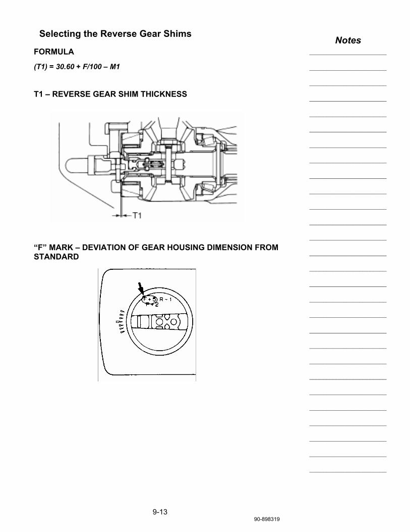
9-1390-898319
Selecting the Reverse Gear Shims
FORMULA
(T1) = 30.60 + F/100 – M1
T1 – REVERSE GEAR SHIM THICKNESS
“F” MARK – DEVIATION OF GEAR HOUSING DIMENSION FROM STANDARD
Notes _______________________
_______________________
_______________________
_______________________
_______________________
_______________________
_______________________
_______________________
_______________________
_______________________
_______________________
_______________________
_______________________
_______________________
_______________________
_______________________
_______________________
_______________________
_______________________
_______________________
_______________________
_______________________
_______________________
_______________________
_______________________
_______________________
_______________________
_______________________

90-898319 9-14
M1 – REVERSE GEAR BEARING HEIGHT
T1 RESULTS – ROUNDING TABLE
Calculated Numeral at 1/100 Place Rounded Numeral
1, 2 0
3, 4, 5 2
6, 7, 8 5
9, 10 8
LAB EXCERCISE
ACTUAL
T1 = 30.60 + F/100 - M1
_______ = 30.60 + _____/100= ______ _____

9-1590-898319
Selecting the Forward Gear Shims
FORMULA
(T2) = 8.45 + R/100 – A/100 – M5 + M6
T2 - FORWARD GEAR SHIM THICKNESS, M5 & M6 BEARING HEIGHT
“R” MARK – GEAR HOUSING DIMENSION DEVIATION FROM STANDARD
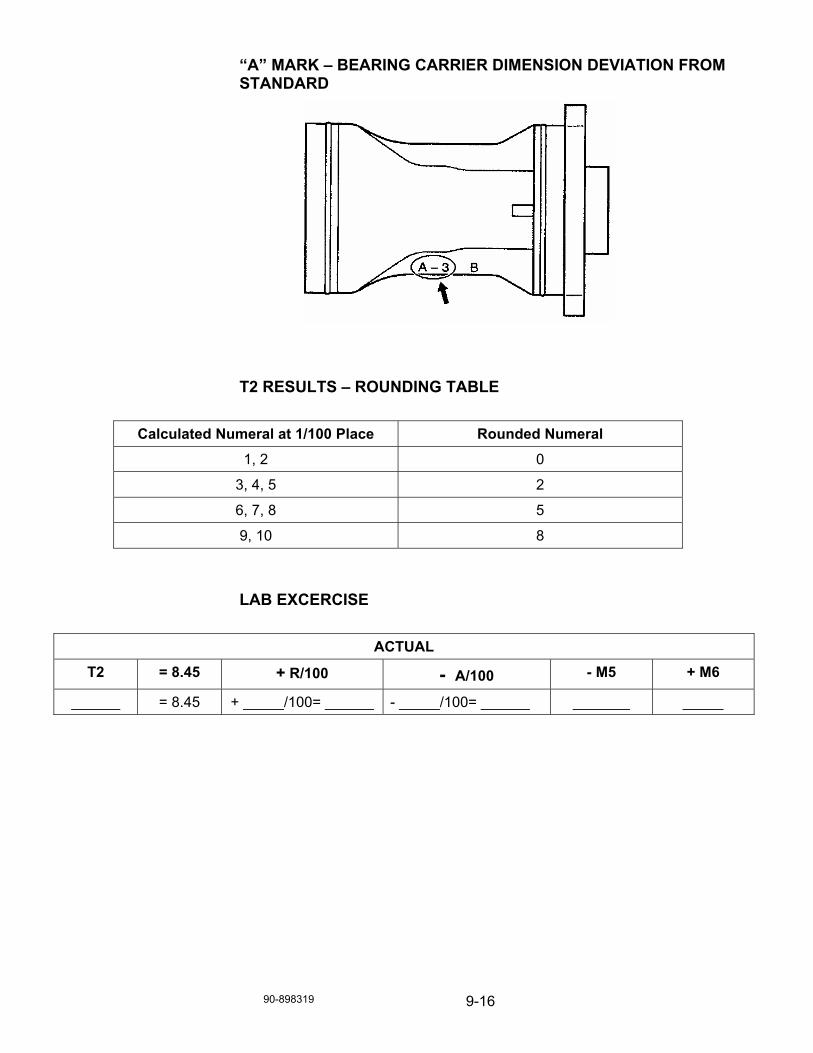
90-898319 9-16
“A” MARK – BEARING CARRIER DIMENSION DEVIATION FROM STANDARD
T2 RESULTS – ROUNDING TABLE
Calculated Numeral at 1/100 Place Rounded Numeral
1, 2 0
3, 4, 5 2
6, 7, 8 5
9, 10 8
LAB EXCERCISE
ACTUAL
T2 = 8.45 + R/100 - A/100 - M5 + M6
______ = 8.45 + _____/100= ______ - _____/100= ______ _______ _____

9-1790-898319
Selecting Propeller Shaft Shims a - Nut b - Tab washer c - Taper roller bearing d - Thrust bearing e - Shim (AR) a - Ring nut wrench (91-888880T) (Stamped 06578) b - Tab washer c - Nut a - 0.25-0.35mm (0.01-0.014 in.)
Notes _______________________
_______________________
_______________________
_______________________
_______________________
_______________________
_______________________
_______________________
_______________________
_______________________
_______________________
_______________________
_______________________
_______________________
_______________________
_______________________
_______________________
_______________________
_______________________
_______________________
_______________________
_______________________
_______________________
_______________________
_______________________
_______________________
_______________________
_______________________

90-898319 9-18
Measuring Backlash
REVERSE GEAR a - Puller jaws (91-46086A1) b - Universal puller screw (91-85716) a - Backlash indicator b - Puller c - Dial indicator
Reverse Gear Backlash Shim Thickness
Less than 0.35 mm To be decreased by
(0.53 – M) x 0.71
More than 0.70 mm To be increased by
(M – 0.53) x 0.71 M = Measurement
Available Shim Thickness: 0.10 mm, 0.12 mm, 0.15 mm, 0.18 mm, 0.30 mm, 0.40 mm, and 0.50 mm.
Notes _______________________
_______________________
_______________________
_______________________
_______________________
_______________________
_______________________
_______________________
_______________________
_______________________
_______________________
_______________________
_______________________
_______________________
_______________________
_______________________
_______________________
_______________________
_______________________
_______________________
_______________________
_______________________
_______________________
_______________________
_______________________
_______________________
_______________________
_______________________

9-1990-898319
FORWARD GEAR
Notes _______________________
_______________________
_______________________
_______________________
_______________________
_______________________
_______________________
_______________________
_______________________
_______________________
_______________________
_______________________
_______________________
_______________________
_______________________
_______________________
_______________________
_______________________
_______________________
_______________________
_______________________
_______________________
_______________________
_______________________
_______________________
_______________________
_______________________
_______________________

90-898319 9-20
Forward Gear Backlash Shim Thickness
Less than 0.70 mm To be decreased by
(0.87 – M) x 0.71
More than 1.03 mm To be increased by
(M – 0.87) x 0.71 M = Measurement
Available Shim Thickness: 0.10 mm, 0.12 mm, 0.15 mm, 0.18 mm, 0.30 mm, 0.40 mm, and 0.50 mm.
Notes _______________________
_______________________
_______________________
_______________________
_______________________
_______________________
_______________________
_______________________
_______________________
_______________________
_______________________
_______________________
_______________________
_______________________
_______________________
_______________________
_______________________
_______________________
_______________________
_______________________
_______________________
_______________________
_______________________
_______________________
_______________________
_______________________
_______________________
_______________________

10-1 90-898319
Section 10 - High Performance Gearcases

10-3 90-898319
Table of Contents Table of Contents..............................................................................................3 High Performance Gearcases...........................................................................4
Warranty........................................................................................................4 Recommended Outboard Mounting Height ...................................................4 Standard Gear Housing Assembly ................................................................5 Mercury Hi-Performance Torque Master / Fleetmaster Gear Housing Assembly.......................................................................................................6 Mercury Hi-Performance Sport Master Gear Case Assembly.......................7 Mercury Hi-Performance CLE Gear Housing Assembly................................7 Hi-Performance Internal Components ...........................................................8 2.5L Hi-Performance Gear Cases .................................................................9 3.0L Hi-Performance Gear Cases ...............................................................10 Solid or Firm Motor Mounts .........................................................................11 Draining/Inspecting Lubricant ......................................................................12 Clutch Cross Pin..........................................................................................13 Propshaft Upgrade ......................................................................................14 Accessories .................................................................................................15
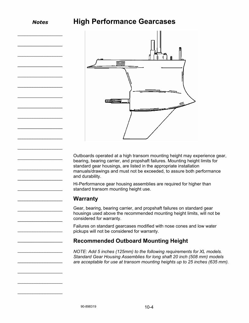
90-898319 10-4
High Performance Gearcases Outboards operated at a high transom mounting height may experience gear, bearing, bearing carrier, and propshaft failures. Mounting height limits for standard gear housings, are listed in the appropriate installation manuals/drawings and must not be exceeded, to assure both performance and durability.
Hi-Performance gear housing assemblies are required for higher than standard transom mounting height use.
Warranty Gear, bearing, bearing carrier, and propshaft failures on standard gear housings used above the recommended mounting height limits, will not be considered for warranty.
Failures on standard gearcases modified with nose cones and low water pickups will not be considered for warranty.
Recommended Outboard Mounting Height
NOTE: Add 5 inches (125mm) to the following requirements for XL models. Standard Gear Housing Assemblies for long shaft 20 inch (508 mm) models are acceptable for use at transom mounting heights up to 25 inches (635 mm).
Notes
__________________
__________________
__________________
__________________
__________________
__________________
__________________
__________________
__________________
__________________
__________________
__________________
__________________
__________________
__________________
__________________
__________________
__________________
__________________
__________________
__________________
__________________
__________________
__________________
__________________
__________________

10-5 90-898319
Standard Gear Housing Assembly
ADVANTAGES 1. Large amount of water inlet area, which reduces low water inlet velocity at
idle, and reduces weed ingestion. 2. Excellent hydrodynamic design for installations below 25 inches (635 mm).
Actually, faster than high performance gear cases at 25 inches (635 mm) and below.
3. Blow-out speed in the low 80 MPH range (depending on the boat and amount of trim angle required to achieve the desired bow-lift).
4. Good exhaust flow through the bearing carrier, which keeps the exhaust back pressure low.
DISADVANTAGES 1. Above 25 inches (635 mm), the upper water inlets may ingest air which
reduces water flow. 2. Above 25 inches (635 mm), the bearing carrier, the two piece prop shaft,
or the prop shaft roller bearing, may become over-stressed and fail, because of the high loads generated by a surfacing propeller.
Notes
__________________
__________________
__________________
__________________
__________________
__________________
__________________
__________________
__________________
__________________
__________________
__________________
__________________
__________________
__________________
__________________
__________________
__________________
__________________
__________________
__________________
__________________
__________________
__________________
__________________

90-898319 10-6
Mercury Hi-Performance Torque Master / Fleetmaster Gear Housing Assembly
NOTE: Torque Master gearcases have a satin finish and Fleetmaster gearcases are painted with silver paint.
These assemblies are recommended for use at mounting heights of 25 inches (635 mm) to 27 inches (685 mm). Particularly effective on boats that require a fair amount of positive trim to lift the bow
ADVANTAGES 1. Has only the 4 (2.5L) or 5 (3.0L) lower water inlets on the strut, to allow for
higher installations, without ingesting air. 2. Cast in torque tab on skeg, to counteract steering torque, when using
right-hand rotation propellers. 3. Uses all of the high performance internal components (refer to Internal
Components following) for extra strength and durability. 4. The drain/fill plug is removed from the front of the torpedo and relocated in
the bearing carrier. This eliminates a source of cavitation at higher speeds. 5. Provides a slightly higher blow-out speed than the standard production
case because it will run with less “crab-angle” and the relocation of the oil drain/fill plug. This will depend on the boat and the amount of trim-angle required to achieve the desired bow-lift.
DISADVANTAGES 1. May be prone to a little more weed ingestion at idle, because of less inlet
area (higher water inlet velocity). 2. Mounted below 25 inches (635 mm), the Torque Master may be slower
than the production gear case, because of increased hydrodynamic drag. 3. Has a little more exhaust restriction because of heavy duty bearing carrier,
resulting in a little less developed horsepower.
Notes
__________________
__________________
__________________
__________________
__________________
__________________
__________________
__________________
__________________
__________________
__________________
__________________
__________________
__________________
__________________
__________________
__________________
__________________
__________________
__________________
__________________
__________________
__________________
__________________
__________________

10-7 90-898319
Mercury Hi-Performance Sport Master Gear Case Assembly Designed to operate at transom heights of 27 inches (685 mm) to 30 inches (762 mm). Used on lightweight, performance hulls, that have natural bow lift. Straight-skeg versions available for multiple engine applications.
Mercury Hi-Performance CLE Gear Housing Assembly These assemblies are recommended for use at mounting heights of 27 inches (685 mm) to 30 inches (760 mm). Particularly effective on boats that require little to no positive trim, to achieve maximum speed. This means that the boat must have a great amount of hydrodynamic and/or aerodynamic lift designed into the boat.
ADVANTAGES 1. Below-the-torpedo water inlets allow for these extremely high installations. 2. High performance internal components for extra strength (refer to Internal
Components following). 3. Very high blow-out speeds (mid 90 MPH on V-bottoms to 100+ MPH on
some air entrapment type hulls). 4. Cast-in torque-tab to compensate for steering torque with right hand
rotation props. Torque-tab removed on counter-rotation units. 5. When set up ideally, the pointed nose of the torpedo will be at the water
surface, and provides the least amount of hydrodynamic drag of all of these gearcases.
Notes
__________________
__________________
__________________
__________________
__________________
__________________
__________________
__________________
__________________
__________________
__________________
__________________
__________________
__________________
__________________
__________________
__________________
__________________
__________________
__________________
__________________
__________________
__________________
__________________
__________________

90-898319 10-8
DISADVANTAGES 1. Has the same exhaust restriction as the Torquemaster, because of the
heavy duty bearing carrier resulting in a little less developed horsepower than the standard gear case.
2. More prone to weed-ingestion at idle, because of smaller water inlet area and high water velocity. Although, the 4 hole CLE inlet is the best compromise between weed ingestion and speed.
3. Very slow gear case running sub-surface, because of the increase in hydrodynamic drag.
4. Running too deep may also cause the torque tab to over compensate for the lack of propeller torque and cause ill handling.
5. Does not react well to boats requiring a high degree of positive trim, to achieve desired bow-lift.
NOTE: See pages 49 & 50 of “Everything You Should Know About Propellers - Fourth Edition“ for a full explanation of “Blow-Out”.
WARNING
Loss of boat control at high speed can result in serious injury or death. Testing for blow-out should be done by a highly experienced and competent driver. Certain boats (expecially V-Bottoms) may react violently to a high speed blow-out. An experienced driver can usually feel a blowout starting to occur before the boat loses lift and veers to one side. Never perform blowout testing with passengers. Always wear high quality, high performance life jacket. Always have a safety boat present. Read the lanyard stop switch information in the operation and maintenance manual before electing to install, use, or not to use such a switch.
Hi-Performance Internal Components Combined with the cast-in torque tab, moving the oil fill screw, redesigning and relocating the water inlets, some internal components are also different from the standard gear housings assemblies. These differences allow operation at higher transom heights.
Bearing Carrier - Thicker and stronger casting.
Bearing Carrier Retaining Nut - Thicker and stronger.
Bearing Carrier Bearings - Larger for increased durability.
Propeller Shaft - Larger one piece carbon steel chrome plated for increased strength.
Drive Shaft - One piece carbon steel chrome plated for increased strength.
Clutch Cross Pin - Threaded for increased retention.
Notes
__________________
__________________
__________________
__________________
__________________
__________________
__________________
__________________
__________________
__________________
__________________
__________________
__________________
__________________
__________________
__________________
__________________
__________________
__________________
__________________
__________________
__________________
__________________
__________________
__________________
__________________

10-9 90-898319
2.5L Hi-Performance Gear Cases
Torquemaster Sportmaster CLE Profile Rounded Nose PointedNose PointedNose
Finish Satin Polished Painted
Water Pickup 4 Upper Holes (Per Side)
3 Lower Nose Holes 4 Lower Nose Holes
Oil Fill Spool Only Spool Only Nose & Spool
Oil Vent Port Side Starboard Side Starboard Side
Torque Tab Yes With or Without With or Without
Trim Tab Flat Anodic Plate Flat Anodic Plate Flat Anodic Plate
Upper Side Anodes Yes Yes Yes
Rotation Standard (RH) Standard (RH) and
Counter Rotation (LH)
Standard (RH) and
Counter Rotation (LH)
Gear Ratio 1.87 & 2.00 1.62 – 1.75 – 1.87-2.00 1.87 – 2.00

90-898319 10-10
3.0L Hi-Performance Gear Cases
Torquemaster Sportmaster CLE Profile Rounded Nose Rounded Nose Pointed Nose
Finish Satin Silver Paint Satin
Water Pickup 5 Upper Holes (Per Side)
5 Upper Holes (Per Side)
3 Lower Nose Holes
Oil Fill Spool Only Nose Spool Only
Oil Vent Port Side Port Side Starboard Side
Torque Tab (Skeg) Yes No With or Without
Trim Tab Flat Anodic Plate Flat Anodic Plate Flat Anodic Plate
Upper Side Anodes Yes Yes Yes
Rotation Standard (RH) Standard (RH) and Counter Rotation (LH)
Standard (RH) and Counter Rotation (LH)
Gear Ratio 1.62 & 1.75 1.75 1.62 & 1.75

10-11 90-898319
Solid or Firm Motor Mounts Outboard motors, intended for general use, are designed with rubber motor mounts, suitably soft to isolate most of the engine vibrations from the boat. On some fast boats, where delicate control becomes more essential, it may be desirable to incorporate mounts with reduced, or no flexibility. Of course, with the use of such alternate mounts, comes increased boat vibrations.
CAUTION
Outboard powered boats capable of exceeding 80 MPH should use solid engine mounts and a Hi-Performance gear case.
Notes
__________________
__________________
__________________
__________________
__________________
__________________
__________________
__________________
__________________
__________________
__________________
__________________
__________________
__________________
__________________
__________________
__________________
__________________
__________________
__________________
__________________
__________________
__________________
__________________
__________________

90-898319 10-12
Draining/Inspecting Lubricant 1. Place gear housing in a suitable holding fixture or vise, with the driveshaft
in a vertical position, as shown. 2. Position a clean drain pan under gear housing and remove “Fill” and
“Vent” screws from gear housing. a) Fill Screw (Located in the bearing carrier) b) Vent Screw c) Drain Pan d) Water Passage Covers
NOTE: Inspect o-rings under water passage covers, if overheating conditions exist.
Notes
__________________
__________________
__________________
__________________
__________________
__________________
__________________
__________________
__________________
__________________
__________________
__________________
__________________
__________________
__________________
__________________
__________________
__________________
__________________
__________________
__________________
__________________
__________________
__________________
__________________
__________________

10-13 90-898319
Clutch Cross Pin a) Cross Pin b) Cross Pin tang c) Cross pin Tool 91-86642-1 a) Threaded Cross Pin tool (91-86642-2) b) Slotted Cross Pin Tool (91-86642-1)
Notes
__________________
__________________
__________________
__________________
__________________
__________________
__________________
__________________
__________________
__________________
__________________
__________________
__________________
__________________
__________________
__________________
__________________
__________________
__________________
__________________
__________________
__________________
__________________
__________________
__________________

90-898319 10-14
Propshaft Upgrade The diameter of the spline area for the propeller has been increased and the number of splines has changed from 15 to 19 spline. These new propshafts give greater durability in surface type applications. The heavy duty propshaft requires use of propellers with replaceable hubs.
Hub kit part number for heavy duty propshaft: 840389A2
Propshafts are for illustration only and do not represent any particular model. a) Standard Mercury Racing Propshaft Prior to 2001 Model Year b) Heavy Duty Mercury Racing Propshaft Starting With 2001 Model Year c) Diameter of 1 in (25 mm) d) Diameter of 1.25 in (32 mm) e) 15 Splines f) 19 Splines
Tip: HD Propshaft Cover Nut Tool is required for disassembly/reassembly (91-840393).
Notes
__________________
__________________
__________________
__________________
__________________
__________________
__________________
__________________
__________________
__________________
__________________
__________________
__________________
__________________
__________________
__________________
__________________
__________________
__________________
__________________
__________________
__________________
__________________
__________________
__________________
__________________
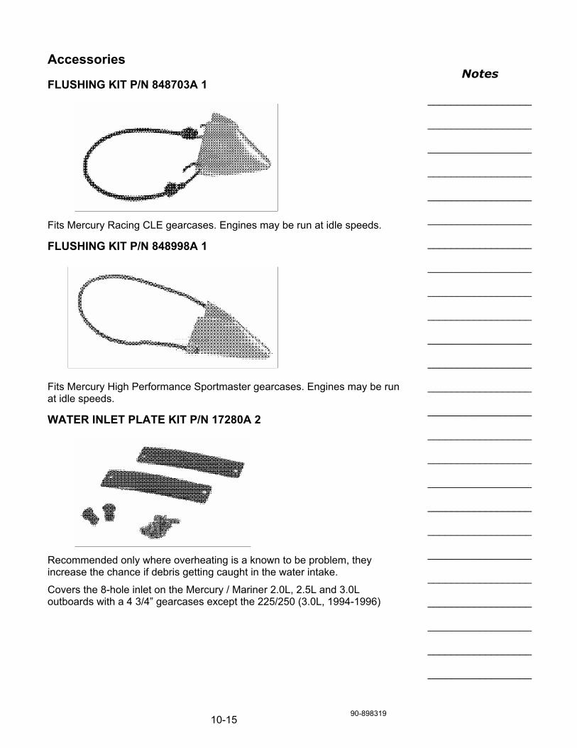
10-15 90-898319
Accessories
FLUSHING KIT P/N 848703A 1 Fits Mercury Racing CLE gearcases. Engines may be run at idle speeds.
FLUSHING KIT P/N 848998A 1 Fits Mercury High Performance Sportmaster gearcases. Engines may be run at idle speeds.
WATER INLET PLATE KIT P/N 17280A 2 Recommended only where overheating is a known to be problem, they increase the chance if debris getting caught in the water intake.
Covers the 8-hole inlet on the Mercury / Mariner 2.0L, 2.5L and 3.0L outboards with a 4 3/4” gearcases except the 225/250 (3.0L, 1994-1996)
Notes
__________________
__________________
__________________
__________________
__________________
__________________
__________________
__________________
__________________
__________________
__________________
__________________
__________________
__________________
__________________
__________________
__________________
__________________
__________________
__________________
__________________
__________________
__________________
__________________
__________________

90-898319 10-16
WATER INLET COVER
P/N 881150Q 1 or 881150K 1 • Used to cover the front inlets of the 3.0 Liter dual water inlet lower units.
• The cover will prevent air from being drawn into the front inlets when engine is being run using the side water inlets only.
WATER INLET PLATE KIT P/N 832066A 1 Recommended only where overheating is a known to be problem, they increase the chance if debris getting caught in the water intake.
Covers the 5-hole inlet on the Mercury / Mariner 225/250 (3.0L, 1994-1996) outboards.
Notes _______________________
_______________________
_______________________
_______________________
_______________________
_______________________
_______________________
_______________________
_______________________
_______________________
_______________________
_______________________
_______________________
_______________________
_______________________
_______________________
_______________________
_______________________
_______________________
_______________________
_______________________
_______________________
_______________________
_______________________
_______________________
_______________________
_______________________
_______________________

Notes:SECTION - 11 VERADO GEAR HOUSING
90-898319 AUGUST 2005 Page 11-1
SECTION 11 - VERADO GEAR HOUSINGTable of ContentsVerado L6 and L4 SC Gear Housing................................................................................. 2
Special Tools............................................................................................................... 2Gear Housing Components......................................................................................... 6Driveshaft ................................................................................................................... 6Drive Shaft Seal Carrier .............................................................................................. 7Shift Crank .................................................................................................................. 8Prop shaft ................................................................................................................... 8Bearing Carrier ........................................................................................................... 9Bearing Carrier and Gear Assembly ......................................................................... 10Counter Rotation Gear Housing Components.......................................................... 11Gear Housing Components Comparison .................................................................. 11Reverse Gear ........................................................................................................... 11Forward Gear ........................................................................................................... 11Pinion Gear Height.................................................................................................... 12Tapered Rolling Bearing Diagnoses.......................................................................... 14Bent Cage ................................................................................................................. 15Etching ...................................................................................................................... 15Misalignment ............................................................................................................ 15Fatigue Spalling ....................................................................................................... 16Heat Discoloration .................................................................................................... 16Galling ..................................................................................................................... 16Brinelling ................................................................................................................... 16Cage Wear ............................................................................................................... 17Abrasive Roller Wear ................................................................................................ 17Cracked Inner Race .................................................................................................. 17Smears ..................................................................................................................... 17Frettage .................................................................................................................... 18

Notes:VERADO GEAR HOUSING SECTION - 11
Page 11-2 90-898319 AUGUST 2005
Verado L6 and L4 SC Gear HousingSpecial Tools
Bearing Carrier Retainer Nut Wrench 91‑61069T
ob01615
Installs and removes the bearingcarrier retainer nuts.
Puller Jaws AssemblyPuller Bolt
91‑46086A191‑85716
ob01616
Removes bearing carrier andbearing races.
Slide Hammer Puller 91‑34569A1
ob01617
Removes bearings and bearingraces.
Bearing Removal and Installation Kit 91‑31229A7
2966
Installs and removes the bearingsin all gearcases.91‑31229A7 tool assemblyincludes the followingcomponents:11‑24156 Hex Nut12‑34961 Washer91‑15755T Bearing Carrier91‑29310 Plate91‑29610 Pilot Plate91‑30366T1 Mandrel91‑31229 Puller Shaft91‑32325T Driver Head91‑32336 Driver Needle Bearing91‑36379 Puller/Head Gear91‑36569T Driver Head91‑36571T Pilot Washer91‑37292 Roller Bearing91‑37311 Driver Head91‑37312 ‑Driver Head91‑37323 Driver Head Rod91‑37324 Pilot Washer91‑38628T Puller/Driver Head91‑52393 Driver Needle Bearing91‑52394 Head Pull Rod
Pilot Washer 91‑36571T
ob01619
Used in pinion gear and pinionbearing installation.

Notes:SECTION - 11 VERADO GEAR HOUSING
90-898319 AUGUST 2005 Page 11-3
Puller/Driver Head 91‑38628
ob01622
Used in pinion gear and pinionbearing installation.
Driver Rod 91‑37323
ob01623Used in pinion gear and pinionbearing installation.
Universal Puller Plate 91‑37241
8505
Removes bearings from gearsand the driveshaft.
Pinion Gear Locating Tool 91‑12349A05
3608
Measures pinion gear height.
Pinion Gear Locating Tool 91‑56048001
ob01627
Measures pinion gear height.
Backlash Indicator Rod 91‑78473
ob01628
Checks the gear backlash on the1.86:1 ratio gear housings.
Dial Indicator 91‑58222A1
ob01629
Measures gear backlash andpinion gear location.
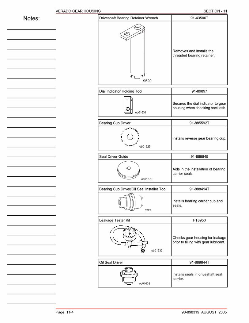
Notes:VERADO GEAR HOUSING SECTION - 11
Page 11-4 90-898319 AUGUST 2005
Driveshaft Bearing Retainer Wrench 91‑43506T
9520
Removes and installs thethreaded bearing retainer.
Dial Indicator Holding Tool 91‑89897
ob01631
Secures the dial indicator to gearhousing when checking backlash.
Bearing Cup Driver 91‑885592T
ob01625
Installs reverse gear bearing cup.
Seal Driver Guide 91‑889845
ob01670
Aids in the installation of bearingcarrier seals.
Bearing Cup Driver/Oil Seal Installer Tool 91‑888414T
6229
Installs bearing carrier cup andseals.
Leakage Tester Kit FT8950
ob01632
Checks gear housing for leakageprior to filling with gear lubricant.
Oil Seal Driver 91‑889844T
ob01633
Installs seals in driveshaft sealcarrier.

Notes:SECTION - 11 VERADO GEAR HOUSING
90-898319 AUGUST 2005 Page 11-5
Driver Head 91‑36569T
ob01634
Used in pinion gear and bearinginstallation.
Propeller Shaft Adapter 91‑61077
ob01635
Provides a wrench surface to turnthe propeller shaft.
Pinion Nut Wrench 91‑61067003
ob01639
Holds the pinion nut whenremoving the pinion gear anddriveshaft.
Driveshaft Holding Tool 91‑889958T
ob01206
Holds driveshaft during pinion nutremoval on the Verado models.
Dial Indicator Adaptor 91‑83155
2999
Attaches the dial indicator to thegearcase when checkingbacklash.
Bearing Puller Assembly 91‑83165T
3610
Removes bearings, bearingcarriers, and bearing races.
Bearing Removal Tool 91‑816245
3655
Removes forward gear bearing inbearing adaptor.

Notes:VERADO GEAR HOUSING SECTION - 11
Page 11-6 90-898319 AUGUST 2005
Guide Plate 91‑816243
4481
Centers the rod used to drive inthe forward gear bearing on astandard rotation gearcase, andthe reverse gear bearing on acounter rotation gearcase.
Oil Drain Funnel 91‑892866A01
4993
Diverts draining engine oil fromcontacting the anti‑splash andanti‑cavitation plates.
Gear Housing ComponentsIMPORTANT: For step by step procedures please reference the currentservice manualThe gear housing for the L6 and L4 is significantly larger to incorporatelarger gears, and increasing the durability. The exclusive hydrodynamicprofile increases blowout speed in most applications for safer high speedoperation. Dual water pickups ensure proper cooling under most runningconditions. Improved corrosion resistance through EDP (ElectroDeposition Painting) of all internal water passages.
Gear Housing Specifications
L6 Gear Ratio 1.85:1
L4 SC Gear Ratio 2.08:1
15001
DriveshaftThe driveshaft is similar to the earlier 3.0L with exception to the fine pitchsplines for added strength, and wear resistant high temperaturedriveshaft seals.Consider the following procedure if the pinion gear is seized onto the driveshaft:a. Place gear housing in vise using soft jaw vise covers.b. Place a block of wood on gear housing mating surface.c. Use a mallet and carefully tap gear housing away from driveshaft.IMPORTANT: Be careful when the driveshaft is removed. Pinion bearingrollers are free to fall out of the pinion bearing.

Notes:SECTION - 11 VERADO GEAR HOUSING
90-898319 AUGUST 2005 Page 11-7
NOTE: The shim and bearings are packaged as an assembly.NOTE: The upper driveshaft cup is a slip fit within the driveshaft bore andmay show signs of movement. All other bearing cups are press fit andshould not show any signs of movement.
15277
abcde
f
g
g
a - Shimb - Cupc - Spacerd - Cup
e - Retainerf - Pinion bearing surfaceg - Tapered roller bearing
assembly
Drive Shaft Seal CarrierGear housing operating pressure can become excessive under certainconditions, triggering the driveshaft oil seal carrier to be pushed upward.This upward pressure bends the base plate of the water pump, whichcauses water pump impeller and base plate damage. The seal carrier inthe Verado gear housing is retained with a snap ring to ensure its position.
15002
a
b
c
d
a - Retaining ringb - Oil seal carrier
c - O‑ringd - High temperature water
resistant seals

Notes:VERADO GEAR HOUSING SECTION - 11
Page 11-8 90-898319 AUGUST 2005
Shift CrankThe shift crank in a standard rotating gear housing has the locating tabfacing aft towards the propeller of this gear housing. In counter rotatinggear housing, the locating tab faces towards the bow of the boat.
a
15297
a - Locating tab
Prop shaftThe following factors are unique to the Verado prop shaft:• The prop shaft and clutch have additional splines for added strength.• The prop shaft end play has been eliminated by way of a dual taper
roller bearing design.• The tapered roller bearing is packaged as an assembly.• Gear and propeller shaft assembly can only be removed from gear
housing after driveshaft and pinion gear have been removed.
a - Tapered roller bearingb - Additional clutch splinesc - Tapered roller bearingd - Utilizes existing 3.0L
propellers
e - Eliminated end playf - Retaining ringg - Thrust washerh - Cup
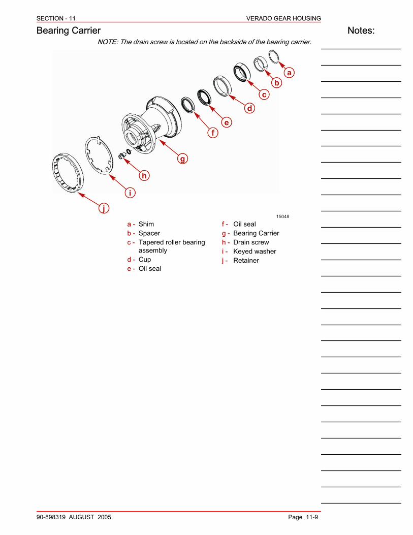
Notes:SECTION - 11 VERADO GEAR HOUSING
90-898319 AUGUST 2005 Page 11-9
Bearing CarrierNOTE: The drain screw is located on the backside of the bearing carrier.
15048
a - Shimb - Spacerc - Tapered roller bearing
assemblyd - Cupe - Oil seal
f - Oil sealg - Bearing Carrierh - Drain screwi - Keyed washerj - Retainer

Notes:VERADO GEAR HOUSING SECTION - 11
Page 11-10 90-898319 AUGUST 2005
Bearing Carrier and Gear Assembly
a - Ball bearingb - Tapered roller bearing
c - Bearing carrier
The propeller shaft utilizes two tapered roller bearing and cup assembliesfor propeller shaft support. The tapered bearing is behind the bearingcarrier seals. The reverse gear assembly on standard gear housing (orforward gear and bearing adaptor on counter rotation gear housing) mustbe removed from the bearing carrier to gain access to this bearing forinspection. The other tapered bearing is located inside the gearassembly.NOTE: Gear bearing should not be removed from gear unlessreplacement is necessary. Bearing is not reuse able if bearing isremoved.
ob01642
a
b
c
d
e
f
a - Snap ringb - Flat washerc - Tapered bearing race
d - Tapered roller bearinge - Gear bearingf - Gear

Notes:SECTION - 11 VERADO GEAR HOUSING
90-898319 AUGUST 2005 Page 11-11
Counter Rotation Gear Housing ComponentsGear Housing Components Comparison
Components Standard Counter
Driveshaft Identical
Water Pump Identical
Shift Shaft Identical
Anodes Identical
Prop Shaft Identical
Bearing Carrier Bearing adaptor does notapply Bearing adaptor
Bearing Removal Tool (forapplications with bearingadaptor)
91‑816245
Gear Housing Identical
Reverse GearReverse gear shimming is the same as forward gear on a standardrotation.
a
b
cd
ef
g
h 15050
a - Shimb - Cupc - Roller bearingd - Retaining ring
e - Thrust washerf - Cupg - Roller bearing assemblyh - Reverse gear
Forward GearShimming behind the bearing adapter sets the forward gear backlash.The condition of the bearing surface on the forward gear, is an indicationof the condition of the bearings. Replace the bearings if the surface of thegear and/or thrust washer is pitted, groved, scored, worn unevenly,discolored from overheating or has embedded metal particles.

Notes:VERADO GEAR HOUSING SECTION - 11
Page 11-12 90-898319 AUGUST 2005
IMPORTANT: Do not remove the roller bearing from the bearing adaptorunless replacement is necessary. The roller bearing should not be usedafter it has been removed from bearing adaptor.
ob01596
a b c d ef
a - Forward gearb - Thrust washerc - Thrust bearing
d - Roller bearinge - Bearing Adaptorf - Shim
Gear Housing Set UpPinion Gear Height
Use the Pinion Gear Locating Tool 91‑56048001, when the prop shaft isinstalled.
ob01433
b
aa - Pinion Gear Locating
Toolb - Feeler gauge
Pinion Gear Locating Tool 91‑56048001

Notes:SECTION - 11 VERADO GEAR HOUSING
90-898319 AUGUST 2005 Page 11-13
3Use Pinion Gear Locating Tool ,91‑12349A05 when the prop shaft isnot installed.
3174
a
bcdc
e
f
a - Feeler gaugeb - Pinion Gear Locating
Toolc - Disc #2
d - Flat #4e - .64 mm (.025 in.)f - Pinion gear
Pinion Gear Locating Tool 91‑12349A05
Propeller Shaft Bearing PreloadA preload on the propeller shaft is set using a spacer and shim betweenthe shaft and the rear propeller shaft bearing. All gear housingcomponents must be installed and correctly shimmed before checkingpropeller shaft bearing preload. The propeller shaft tapered roller bearingmust be properly seated in the race during installation. Driveshaft retainershould be torqued to specification listed in the current service manual.
ob01050
95
95
a95
b
c
a - Bearing carrierassembly
b - Propeller shaft bearing
c - Preload spacer

VERADO GEAR HOUSING SECTION – 11
_________________________________________________________________________ Page 11-14 90-898319 AUGUST 2005
Notes: Tube Ref No. Description Where Used Part No.
2-4-C with Teflon
Bearing carrier retainer nut threads and
corresponding gear housing threads,
bearing carrier O-ring, upper driveshaft bearing retainer
threads.
92-802859A1
Description Nm lb. in. lb. ft. Bearing rolling torque (new bearings) 1.1 - 1.8 10 - 16 Bearing rolling torque (used bearings) 0.45 - 1.1 4 - 10
Backlash Measurements
Backlash measurements are taken in the same manner as other gear housing. Tighten the indicator tool onto the driveshaft so that the needle in the dial makes at least one full revolution and come to "0" on the indicator scale. a. Install a dial indicator and align the dial indicator pointer so that it is
perpendicular to and touching the "I" mark on the dial indicator tool. b. Tighten the indicator tool onto the driveshaft so that the needle in the
dial makes at least one full revolution and come to "0" on the indicator scale.
a - Nuts (4) (obtain locally) b - Threaded rod - 9.5 mm (3/8 in.) (obtain locally) c - Dial Indicator Holding Tool
d - Dial Indicator e - Indicator pointer f - Backlash indicator rod
Tapered Rolling Bearing Diagnoses
Consider the following factors when diagnosing bearing condition: • General condition of all parts during disassembly and inspection. • Classify the failure with the aid of the illustrations. • Determine the cause. • Make all repairs following recommended procedures.

Notes:SECTION - 11 VERADO GEAR HOUSING
90-898319 AUGUST 2005 Page 11-15
Bent Cage• Damage due to improper handling or tool usage.• Replace bearing.
17181a
a - Bent cage
Etching• Bearing surfaces appear gray or grayish black in color with related
etching away of material usually at roller spacing.• Replace bearings – check seals and check for proper lubrication.
overheat, lubricant failure or overload.
17182
Misalignment• Outer race misalignment due to foreign object. Clean related parts
and replace bearing. Make sure races are properly seated.
17184

Notes:VERADO GEAR HOUSING SECTION - 11
Page 11-16 90-898319 AUGUST 2005
Fatigue Spalling• Flaking of surface metal resulting from fatigue.
17187
Heat Discoloration• Heat discoloration can range from faint yellow to dark blue resulting
from overload or incorrect lubricant.• Excessive heat can cause softening of races or rollers.• To check for loss of temper on races or rollers a simple file test may
be made. A file drawn over a tempered part will grab and cut metal,whereas, a file drawn over a hard part will glide readily with no metalcutting.
• Replace bearings if overheating damage is indicated. Check sealsand other parts.
17188
Galling• Metal smears on roller ends due to overheat, lubrication failure or
overload.• Replace bearing ‑ check seals and check for proper lubrication.
17539
Brinelling• Surface indentations in raceway caused by rollers either under
impact loading or vibration while the bearing is not rotating.

Notes:SECTION - 11 VERADO GEAR HOUSING
90-898319 AUGUST 2005 Page 11-17
• Replace bearing if rough or noisy.
17543
Cage Wear• Wear around outside diameter of cage and roller pockets caused by
abrasive material and inefficient lubrication.• Check seal and replace bearing.
17545
Abrasive Roller Wear• Pattern on races and rollers caused by fine abrasives.• Clean all parts and housings, check seals and bearings.• Replace bearings rough or noisy.
17550
Cracked Inner Race• Race cracked due to improper fit, cocking, or poor bearing seals.
17552
Smears• Smearing of metal due to slippage.• Slippage can be caused be poor fits, lubrication, overheating,
overloads or handling damage.• Replace bearings. Clean related parts and check for proper fit and
lubrication.
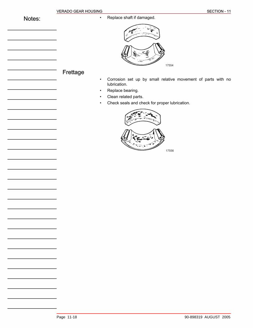
Notes:VERADO GEAR HOUSING SECTION - 11
Page 11-18 90-898319 AUGUST 2005
• Replace shaft if damaged.
17554
Frettage• Corrosion set up by small relative movement of parts with no
lubrication.• Replace bearing.• Clean related parts.• Check seals and check for proper lubrication.
17556